EP1930731A2 - Vorrichtung und Verfahren zur Beschleunigungserfassung und Leerlaufsteuervorrichtung damit - Google Patents
Vorrichtung und Verfahren zur Beschleunigungserfassung und Leerlaufsteuervorrichtung damit Download PDFInfo
- Publication number
- EP1930731A2 EP1930731A2 EP07122216A EP07122216A EP1930731A2 EP 1930731 A2 EP1930731 A2 EP 1930731A2 EP 07122216 A EP07122216 A EP 07122216A EP 07122216 A EP07122216 A EP 07122216A EP 1930731 A2 EP1930731 A2 EP 1930731A2
- Authority
- EP
- European Patent Office
- Prior art keywords
- acceleration
- vehicle
- detected
- stationary
- stopped
- Prior art date
- Legal status (The legal status is an assumption and is not a legal conclusion. Google has not performed a legal analysis and makes no representation as to the accuracy of the status listed.)
- Granted
Links
Images


Classifications
-
- B—PERFORMING OPERATIONS; TRANSPORTING
- B60—VEHICLES IN GENERAL
- B60W—CONJOINT CONTROL OF VEHICLE SUB-UNITS OF DIFFERENT TYPE OR DIFFERENT FUNCTION; CONTROL SYSTEMS SPECIALLY ADAPTED FOR HYBRID VEHICLES; ROAD VEHICLE DRIVE CONTROL SYSTEMS FOR PURPOSES NOT RELATED TO THE CONTROL OF A PARTICULAR SUB-UNIT
- B60W40/00—Estimation or calculation of non-directly measurable driving parameters for road vehicle drive control systems not related to the control of a particular sub unit, e.g. by using mathematical models
- B60W40/10—Estimation or calculation of non-directly measurable driving parameters for road vehicle drive control systems not related to the control of a particular sub unit, e.g. by using mathematical models related to vehicle motion
- B60W40/107—Longitudinal acceleration
-
- B—PERFORMING OPERATIONS; TRANSPORTING
- B60—VEHICLES IN GENERAL
- B60W—CONJOINT CONTROL OF VEHICLE SUB-UNITS OF DIFFERENT TYPE OR DIFFERENT FUNCTION; CONTROL SYSTEMS SPECIALLY ADAPTED FOR HYBRID VEHICLES; ROAD VEHICLE DRIVE CONTROL SYSTEMS FOR PURPOSES NOT RELATED TO THE CONTROL OF A PARTICULAR SUB-UNIT
- B60W2520/00—Input parameters relating to overall vehicle dynamics
- B60W2520/10—Longitudinal speed
- B60W2520/105—Longitudinal acceleration
-
- B—PERFORMING OPERATIONS; TRANSPORTING
- B60—VEHICLES IN GENERAL
- B60W—CONJOINT CONTROL OF VEHICLE SUB-UNITS OF DIFFERENT TYPE OR DIFFERENT FUNCTION; CONTROL SYSTEMS SPECIALLY ADAPTED FOR HYBRID VEHICLES; ROAD VEHICLE DRIVE CONTROL SYSTEMS FOR PURPOSES NOT RELATED TO THE CONTROL OF A PARTICULAR SUB-UNIT
- B60W40/00—Estimation or calculation of non-directly measurable driving parameters for road vehicle drive control systems not related to the control of a particular sub unit, e.g. by using mathematical models
- B60W40/02—Estimation or calculation of non-directly measurable driving parameters for road vehicle drive control systems not related to the control of a particular sub unit, e.g. by using mathematical models related to ambient conditions
- B60W40/06—Road conditions
- B60W40/072—Curvature of the road
-
- B—PERFORMING OPERATIONS; TRANSPORTING
- B60—VEHICLES IN GENERAL
- B60W—CONJOINT CONTROL OF VEHICLE SUB-UNITS OF DIFFERENT TYPE OR DIFFERENT FUNCTION; CONTROL SYSTEMS SPECIALLY ADAPTED FOR HYBRID VEHICLES; ROAD VEHICLE DRIVE CONTROL SYSTEMS FOR PURPOSES NOT RELATED TO THE CONTROL OF A PARTICULAR SUB-UNIT
- B60W40/00—Estimation or calculation of non-directly measurable driving parameters for road vehicle drive control systems not related to the control of a particular sub unit, e.g. by using mathematical models
- B60W40/02—Estimation or calculation of non-directly measurable driving parameters for road vehicle drive control systems not related to the control of a particular sub unit, e.g. by using mathematical models related to ambient conditions
- B60W40/06—Road conditions
- B60W40/076—Slope angle of the road
Definitions
- the present invention generally relates to the technological field of detecting acceleration devices and detecting acceleration methods, as well as neutral control devices employing these acceleration devices or methods. More specifically, the present invention relates to correcting an error in a detected acceleration of a vehicle. Aspects of the invention relate to an apparatus, to a device, to a method and to a vehicle.
- a zero point correction of an acceleration sensor is carried out by averaging detected acceleration values each time that the vehicle stops, and adding or subtracting this average value (drift from the zero point of the acceleration sensor) to or from the current detected acceleration value (see for example, Japanese Laid-Open Patent Application No. 7-159438 ).
- the zero point correction aids in eliminating the effect of a sloping road on the acceleration sensor.
- an acceleration detection device for detecting acceleration of a vehicle, comprising a stopped acceleration detector that detects a detected stationary acceleration value when the vehicle is stopped on a sloping road based on an acceleration sensor signal from an acceleration sensor mounted on the vehicle, an acceleration change detector that detects an acceleration change associated with the vehicle transitioning from a stationary state to a driving state on the sloping road based on the acceleration sensor signal, an acceleration estimating unit that estimates an estimated stationary acceleration value based on the acceleration change that was detected by the acceleration change detector and a correcting unit that corrects the detected stationary acceleration value based on a deviation between the estimated stationary acceleration value and the detected stationary acceleration value.
- the device may comprise a vehicle stopped status determination unit configured to determine whether the vehicle is currently stopped, and the stopped acceleration detector detects the detected stationary acceleration value of the vehicle when the vehicle stopped determination unit determines the vehicle is stopped.
- the device may comprise a driving status determination unit that determines whether the vehicle is currently being driven, and the acceleration change detector detects the acceleration change of the vehicle traveled during an interval from a time that the vehicle stopped determination unit determines that the vehicle is stopped until the driving status determination unit determines that the vehicle is currently being driven.
- the device comprises a displacement calculating unit that calculates a displacement amount of the detected stationary acceleration value from a zero point based on the deviation between the estimated stationary acceleration value and the detected stationary acceleration value and the correcting unit performs a zero point correction for the detected stationary acceleration value based on the displacement amount.
- the device may comprise a first filter configured to eliminate noise components included in the acceleration sensor signal.
- the device may comprise a second filter configured to eliminate vehicle spring vibration components included in the acceleration sensor signal.
- the acceleration estimating unit includes an estimated acceleration calculating map in which estimated values of acceleration that correspond to the acceleration change are preset in accordance with vehicle characteristics.
- a neutral control device provided with a device as set out in one or more of the preceding paragraphs, wherein the neutral control device is configured to release an engaging element of an automatic transmission, which engages to start the vehicle moving from a neutral state, when the automatic transmission is in a forward drive position, an accelerator pedal is released, a brake pedal is depressed, and a roadway gradient of the sloping road is below a prescribed angle as determined by the detected stationary acceleration value detected by the acceleration detection device not exceeding an equivalent value to the prescribed angle.
- the correcting unit performs a zero point correction for the detected stationary acceleration value only when an absolute value of the estimated stationary acceleration value when stopped on the sloping road is greater than the absolute value of the detected stationary acceleration value when stopped on the sloping road.
- an acceleration detection device for detecting acceleration of a vehicle, comprising stopped acceleration detecting means for detecting a detected stationary acceleration value when the vehicle is stopped on a sloping road based on an acceleration sensor signal from an acceleration sensor mounted on the vehicle, an acceleration change detecting means for detecting an acceleration change associated with the vehicle transitioning from a stationary state to a driving state on the sloping road based on the acceleration sensor signal, an acceleration estimating means for estimating an estimated stationary acceleration value based on the acceleration change that was detected by the acceleration change detecting means and a correcting means for correcting the detected stationary acceleration value based on a deviation between the estimated stationary acceleration value and the detected stationary acceleration value.
- an acceleration detection method comprising receiving a first acceleration sensor signal from an acceleration sensor mounted on a vehicle when the vehicle is stopped on a sloping road, receiving a second acceleration sensor signal from the acceleration sensor when the vehicle is transitioning from a stationary state to a driving state on the sloping road and correcting detected acceleration values based on the first and second acceleration sensor signals.
- an acceleration detection device for detecting detected acceleration of a vehicle may comprise a stopped acceleration detector, an acceleration change detector, an acceleration estimating unit and a correcting unit.
- the stopped acceleration detector detects a detected stationary acceleration value when the vehicle is stopped on a sloping road based on an acceleration sensor signal from an acceleration sensor mounted on the vehicle.
- the acceleration change detector detects an acceleration change associated with the vehicle transitioning from a stationary state to a driving state on the sloping road based on the acceleration sensor signal.
- the acceleration estimating unit estimates an estimated stationary acceleration value based on the acceleration change that was detected by the acceleration change detector.
- the correcting unit corrects the detected stationary acceleration value based on a deviation between the estimated stationary acceleration value and the detected stationary acceleration value.
- FIG. 1 a system configuration diagram is illustrated depicting a vehicle drive train with a neutral control device embodying the acceleration detection device in accordance with a first embodiment of the present invention.
- the vehicle drive train basically includes an on-board engine 1, an automatic transmission 2 coupled to the engine 1 and an output shaft 3 coupled to the automatic transmission 2.
- the rotational output of the engine 1 undergoes a prescribed modification by the automatic transmission 2, and is then output from the output shaft 3.
- the vehicle is equipped with an engine controller (ECU) 4 and an automatic transmission controller (ATCU) 5 for the purpose of controlling the engine 1, the automatic transmission 2, and the like on the basis of various detection values from various types of sensors, to be discussed later.
- the two controllers 4 and 5 are connected so as to be capable of intercommunication, and constitute a neutral control device.
- the vehicle is provided with various on-board sensors such as an accelerator position sensor 6, a brake switch 7, a vehicle speed sensor 8, an acceleration sensor (G sensor) 9, a shift sensor 10, and the like.
- sensors such as an accelerator position sensor 6, a brake switch 7, a vehicle speed sensor 8, an acceleration sensor (G sensor) 9, a shift sensor 10, and the like.
- the accelerator position sensor 6 outputs an accelerator position signal to the engine controller 4.
- the brake switch 7 outputs a brake switch signal to the engine controller 4 for indicating whether the brake (not shown) pedal has been depressed to apply a braking force to the wheels.
- the vehicle speed sensor 8 detects the driving speed of the vehicle (vehicle speed) on the basis of the rotational speed of the wheels as determined from wheel speed sensors provided to the wheels, and outputs a vehicle speed signal to the engine controller 4.
- the G sensor 9 detects acceleration acting on the vehicle, and outputs an acceleration signal to the engine controller 4.
- the shift sensor 10 detects the shift position of the automatic transmission 2, and outputs a shift position signal to the automatic transmission controller 5.
- the vehicle is considered to be in the neutral state for neutral control by the neutral control device (e.g., the engine controller 4 and the automatic transmission controller 5) shown in Figure 1 , when the shift position of the automatic transmission 2 is in a forward drive position, the accelerator pedal is not depressed, the vehicle is at a stop through depression of the brake pedal, and the gradient of the roadway does not exceed a prescribed angle.
- the clutch (engaging element) 2a of the automatic transmission 2 that engages when the vehicle starts to move will be released, so that neutral control can be performed with the vehicle in the neutral state.
- the accelerator position sensor 6, the brake switch 7, the vehicle speed sensor 8 and the shift sensor 10 cooperate together to constitute a vehicle stopped status determination unit configured to determine whether the vehicle is currently stopped.
- the accelerator position sensor 6, the brake switch 7, the vehicle speed sensor 8 and the shift sensor 10 also cooperate together to constitute a driving status determination unit that determines whether the vehicle is currently being driven.
- the vehicle speed sensor 8 by itself, or some other sensor(s) can be used to constitute the vehicle stopped status determination unit and the driving status determination unit.
- the neutral control device will perform neutral control provided that the shift position signal from the shift sensor 10 indicates a forward drive position, that the accelerator position signal of the accelerator position sensor 6 is zero, that the brake switch signal from the brake switch 7 is ON (indicating the brake pedal is depressed), that the vehicle speed signal from the vehicle speed sensor 8 is a prescribed value (# 0), and that the acceleration signal from the G sensor 9 indicates an acceleration that corresponds to a sloping road of prescribed angle or less.
- the neutral control device will cancel neutral control.
- drift of detected acceleration from the zero point is computed on the basis of a deviation between an estimated value of acceleration during a stop on a sloping road estimated from the change in acceleration occurring during rollback of the vehicle, and a detected value of acceleration during a stop on a sloping road based on the acceleration sensor signal, and then zero point correction of detected acceleration values is performed on the basis of this drift.
- an attempt is made to compute drift more accurately by using highly reliable estimated acceleration during a stop on a sloping road calculated on the basis of a change in acceleration. As a result, more accurate zero point correction can be achieved.
- FIG. 2 is a control block diagram depicting the configuration of the acceleration detection device housed in the engine controller 4 of the illustrated embodiment.
- the acceleration detection device 11 of the illustrated embodiment utilizes rollback of the vehicle when the vehicle is released from the neutral control on a sloping road, and corrects deviation from a zero point (zero point correction) that has occurred in association with changes in temperature or temporal change of the G sensor 9.
- the acceleration detection device 11 of the illustrated embodiment includes a first filter 12, a zero point correcting unit 13, a second filter 14, an N control ON mode G calculating unit 15, an N control OFF mode G calculating unit 16, a AG calculating unit 17, an acceleration estimating unit 18, a drift calculating unit 19, and a G calculating unit 20.
- the N control ON mode G calculating unit 15 constitutes a stopped acceleration detector that detects a detected stationary acceleration value when the vehicle is stopped on a sloping road based on an acceleration sensor signal from the G sensor 9 mounted on the vehicle.
- the N control ON mode G calculating unit 15 detects the detected stationary acceleration value of the vehicle when the vehicle stopped determination unit (e.g., the accelerator position sensor 6, the brake switch 7, the vehicle speed sensor 8 and the shift sensor 10) determines the vehicle is stopped.
- the ⁇ G calculating unit 17 constitutes an acceleration change detector that detects an acceleration change associated with the vehicle transitioning from a stationary state to driving state on a sloping road based on the acceleration sensor signal from the G sensor 9.
- the ⁇ G calculating unit 17 detects the acceleration change of the vehicle traveled during an interval from a time that the vehicle stopped determination unit (e.g., the accelerator position sensor 6, the brake switch 7, the vehicle speed sensor 8 and the shift sensor 10) determines that the vehicle is stopped until the driving status determination unit determines that the vehicle is currently being driven.
- the acceleration estimating unit 18 estimates an estimated stationary acceleration value based on the acceleration change that was detected by the ⁇ G calculating unit 17 (i.e., the acceleration change detector).
- the zero point correcting unit 13 constitutes a correcting unit that corrects the detected stationary acceleration value based on a deviation between the estimated stationary acceleration value and the detected stationary acceleration value.
- the drift calculating unit 19 constitutes a displacement calculating unit that calculates a displacement amount of the detected stationary acceleration value from a zero point based on the deviation between the estimated stationary acceleration value and the detected stationary acceleration value.
- the zero point correcting unit 13 performs a zero point correction for the detected stationary acceleration value based on the displacement amount.
- the first filter 12 eliminates noise components (e.g., those on the order of 6 Hz) contained in the G sensor signal (acceleration signal).
- the zero point correcting unit 13 will correct drift from zero in the G sensor signal that has passed through the first filter 12, and will output the corrected G sensor signal to the second filter 14, to the N control OFF mode G calculating unit 16, and to the G calculating unit 20 (zero point correction).
- the correction method used here is discretionary, and it is also possible to use a method using the nearest preceding single or several drift amounts, or a method using the average value of all previously calculated drift amounts.
- the zero point correction will be carried out only in instances where it has been detected that the roadway gradient, based on the G sensor signal, is excessively small in relation to the actual roadway gradient.
- the second filter 14 eliminates vehicle spring vibration (e.g., about 1 to 2 Hz) contained in the zero point-corrected G sensor signal.
- the N control ON mode G calculating unit 15 will calculate the detected acceleration during a stop on a sloping road.
- the N control OFF mode G calculating unit 16 will calculate the detected acceleration (detected acceleration during rollback) at maximum opening as well as the detected acceleration during a stop on a sloping road detected when the vehicle rolls back immediately following completion of the neutral control.
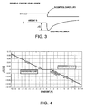
- the ⁇ G calculating unit 17 will calculate an acceleration change ⁇ G occurring that is associated with rollback of the vehicle during transition of the vehicle from being stationary on a sloping road to being driven, i.e., immediately following completion of the neutral control.
- the acceleration estimating unit 18 will calculate sloping-road stop estimated acceleration during a stop on a sloping road.
- the acceleration estimating unit 18 is further provided with a roadway gradient calculating map in which estimated values of acceleration during a stop on a sloping road at various levels of acceleration change ⁇ G associated with rollback of the vehicle are preset for various vehicle characteristics.
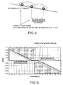
- Figure 4 depicts an estimated roadway gradient calculating map. Estimated acceleration during a stop on a sloping road, i.e., a roadway gradient (%), can be derived in advance experimentally from vehicle characteristics and acceleration change ⁇ G immediately following canceling of neutral control.
- the drift calculating unit 19 is a comparator that outputs a differential value of two input values and calculates the amount of drift (error) of a detected acceleration from the zero point. The calculation is made on the basis of the difference between detected acceleration during a stop on a sloping road and an estimated acceleration during a stop on a sloping road.
- the G calculating unit 20 calculates detected acceleration values from the G sensor signal subsequent to zero point correction. The output of this G calculating unit 20 is used in the neutral control.
- the amount of drift of the detected acceleration values from the zero point is calculated on the basis of deviation between the estimated acceleration during a stop on a sloping road that is estimated from the acceleration change ⁇ G during rollback of the vehicle, and the detected acceleration during a stop on a sloping road that is based on the G sensor signal.
- the zero point correction of detected acceleration is then performed on the basis of this amount of drift.
- the detected acceleration values that are calculated on the basis of the G sensor signal will experience deviation by a certain amount of drift from the true values.
- drift error of the G sensor it will be possible to accurately calculate acceleration change ⁇ G from the G sensor signal during rollback of the vehicle and the G sensor signal during a stop on a sloping road.
- FIG. 5 An example of zero point correction is depicted in Figure 5 .
- a detected acceleration equivalent to a 3% gradient on an uphill slope is detected, and that when the vehicle subsequently rolls back down the uphill slope upon release of the brake, an estimated acceleration equivalent to a 5% gradient (rollback distance corresponding to a 5% gradient) is calculated on the basis of the acceleration change ⁇ G.
- the difference (2%) between the estimated gradient (5%) and the detected gradient (3%) will be calculated as the amount of drift, and the G sensor signal will be offset in the zero point correcting unit 13 in the positive direction by the equivalent of a 2% gradient (in the case of correction by the nearest preceding amount of drift only).
- the acceleration estimating unit 18 is further provided with a map for estimating and calculating acceleration during a stop on a sloping road in which estimated values of acceleration during a stop on a sloping road at various levels of acceleration change ⁇ G associated with rollback of the vehicle are preset for various vehicle characteristics.
- the vehicle will roll backwards when the driver releases the brake during a stop on a sloping road, and the sloping road exceeds a certain gradient.
- the acceleration change ⁇ G of the vehicle generated in accordance with the magnitude of the gradient can be derived in advance through experimentation or simulation. Therefore, by mapping an estimated acceleration during a stop on a sloping road for various levels of acceleration change ⁇ G, the calculation processing overhead can be reduced and estimated value calculations can be accelerated.
- the first filter 12 which eliminates the noise components included in the G sensor signal, is disposed in a pre-stage of the G calculating units 15, 16 and 20. Since the on-board sensors of a vehicle normally contain intermingled noise components, positioning the first filter 12 in a pre-stage of the G calculating units 15, 16 and 20 for eliminating the noise components makes it possible to obtain a G sensor signal that is free from the effects of noise.
- the second filter 14 which eliminates vehicle spring vibration components included in the G sensor signal, is disposed in a pre-stage of the N control OFF mode G calculating unit 15.
- the G sensor signal will contain numerous spring vibration components associated with vibration of the vehicle. Therefore, eliminating the spring vibration components included in the G sensor signal in a pre-stage of the N control OFF mode G calculating unit 15 makes it possible to obtain a G sensor signal that is free from the effects of vehicle vibration.
- the creep force that is transmitted to the wheels from the automatic transmission via a torque converter and that originates from the driving force of the engine at idling speed is not needed when the vehicle is to be kept stationary. Since this creep force must be suppressed by the brakes, the fuel efficiency of the engine will be lower to a corresponding extent.
- neutral refers to a condition approximating neutral, i.e., it includes instances where the automatic transmission clutch is in a half-clutch state.
- the neutral control device of the illustrated embodiment using the acceleration detection device 11 shown in Figure 2 as a roadway gradient detecting device allows the neutral control device (the engine controller 4, the automatic transmission controller 5) to release the engaging element 2a (clutch) in the event that the detected acceleration detected by the acceleration detection device 11 is less than the equivalent of a prescribed gradient.
- the true gradient of the roadway can be detected through zero point correction by the acceleration detection device 11, and unexpected rollback of the vehicle can be reliably avoided.
- the zero point correcting unit 13 will perform zero point correction only in areas indicated as correction targeted regions in the roadway gradient map that corresponds to the acceleration change ⁇ G shown in Figure 6 . Specifically, in the event that the absolute value of estimated acceleration during a stop on a sloping road is greater than the absolute value of detected acceleration during a stop on a sloping road, then the zero point correcting unit 13 will be performed.
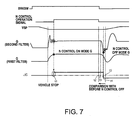
- Figure 7 is a timing chart depicting the operation of zero point correction during a stop on a sloping road in accordance with the illustrated embodiment.
- the brake switch (BRKSW) is ON, the vehicle is at a stop (vehicle VSP of zero and accelerator position of zero), and the roadway gradient is less than a prescribed angle. Therefore, the neutral control is initiated and the automatic transmission 2 goes into neutral. Immediately thereafter, the detected acceleration during a stop on a sloping road is calculated in the N control ON mode G calculating unit 15.
- the vehicle will vibrate appreciably and the G sensor signal will be affected immediately after the vehicle has come to a stop, but the spring vibration components of the vehicle are eliminated by the second filter 14.
- the detected acceleration during a stop on a sloping road can be calculated on the basis of a G sensor signal from which the effects of vibration have been eliminated.
- noise components included in the G sensor signal are eliminated by the first filter 12.
- the vehicle begins to roll back down the hill.
- the difference between the current detected acceleration and the previous detected acceleration during a stop on a sloping road reaches its maximum value.
- the acceleration change ⁇ G will therefore be calculated from the difference between these two detected accelerations in the ⁇ G calculating unit 17.
- An estimated acceleration during a stop on a sloping road can thereby be calculated in the acceleration estimating unit 18 on the basis of the acceleration change ⁇ G.
- the amount of drift of the zero point correction is calculated in the drift calculating unit 19 from the difference between the estimated acceleration during a stop on a sloping road and the detected acceleration during a stop on a sloping road.
- the acceleration detection device of the illustrated embodiment affords effects such as the following, by way of example.
- the acceleration detection device could be appropriately employed in other vehicle control devices as a device for zero point correction of vehicle on-board acceleration sensors.
- the following directional terms "forward, rearward, above, downward, vertical, horizontal, below and transverse” as well as any other similar directional terms refer to those directions of a vehicle equipped with the present invention. Accordingly, these terms, as utilized to describe the present invention should be interpreted relative to a vehicle equipped with the present invention.
- the term “detect” as used herein to describe an operation or function carried out by a component, a section, a device or the like includes a component, a section, a device or the like that does not require physical detection, but rather includes determining, measuring, modeling, predicting or computing or the like to carry out the operation or function.
- the term “configured” as used herein to describe a component, section or part of a device includes hardware and/or software that is constructed and/or programmed to carry out the desired function.
Landscapes
- Engineering & Computer Science (AREA)
- Physics & Mathematics (AREA)
- Automation & Control Theory (AREA)
- Mathematical Physics (AREA)
- Transportation (AREA)
- Mechanical Engineering (AREA)
- Control Of Transmission Device (AREA)
- Regulating Braking Force (AREA)
- Vehicle Body Suspensions (AREA)
Applications Claiming Priority (1)
| Application Number | Priority Date | Filing Date | Title |
|---|---|---|---|
| JP2006330139A JP4556945B2 (ja) | 2006-12-07 | 2006-12-07 | 加速度検出装置および加速度センサのドリフト誤差補正方法ならびにそれを用いたニュートラル制御装置 |
Publications (3)
| Publication Number | Publication Date |
|---|---|
| EP1930731A2 true EP1930731A2 (de) | 2008-06-11 |
| EP1930731A3 EP1930731A3 (de) | 2011-07-27 |
| EP1930731B1 EP1930731B1 (de) | 2012-08-01 |
Family
ID=39304753
Family Applications (1)
| Application Number | Title | Priority Date | Filing Date |
|---|---|---|---|
| EP07122216A Active EP1930731B1 (de) | 2006-12-07 | 2007-12-04 | Vorrichtung und Verfahren zur Beschleunigungserfassung und Leerlaufsteuervorrichtung damit |
Country Status (4)
| Country | Link |
|---|---|
| US (1) | US8340860B2 (de) |
| EP (1) | EP1930731B1 (de) |
| JP (1) | JP4556945B2 (de) |
| CN (1) | CN100593119C (de) |
Cited By (4)
| Publication number | Priority date | Publication date | Assignee | Title |
|---|---|---|---|---|
| WO2012108817A1 (en) * | 2011-02-08 | 2012-08-16 | Scania Cv Ab | Device and method for calibration of an acceleration sensor |
| EP2626709A4 (de) * | 2010-10-05 | 2014-04-02 | Nissan Motor | Beschleunigungserfassungsvorrichtung |
| EP2626708A4 (de) * | 2010-10-05 | 2014-04-16 | Nissan Motor | Beschleunigungserfassungsvorrichtung |
| CN114341651A (zh) * | 2019-10-18 | 2022-04-12 | 株式会社小松制作所 | 加速度检测装置、作业机械以及加速度检测方法 |
Families Citing this family (39)
| Publication number | Priority date | Publication date | Assignee | Title |
|---|---|---|---|---|
| JP4127310B2 (ja) * | 2006-12-27 | 2008-07-30 | トヨタ自動車株式会社 | 車両の制御装置、制御方法、その方法を実現するプログラムおよびそのプログラムを記録した記録媒体 |
| JP5109855B2 (ja) * | 2008-07-30 | 2012-12-26 | 日産自動車株式会社 | 勾配推定装置 |
| JP5663969B2 (ja) * | 2009-06-30 | 2015-02-04 | 株式会社アドヴィックス | 前後加速度制御装置 |
| CN102770771B (zh) * | 2010-02-10 | 2015-03-11 | 丰田自动车株式会社 | 加减速度检测系统 |
| JP5237981B2 (ja) * | 2010-03-09 | 2013-07-17 | ジヤトコ株式会社 | 自動変速機およびその制御方法 |
| JP2012166631A (ja) * | 2011-02-11 | 2012-09-06 | Denso Corp | 踏み間違い対応装置および踏み間違い対応装置用のプログラム |
| JP5477316B2 (ja) * | 2011-03-16 | 2014-04-23 | 株式会社アドヴィックス | 車両ずり下がり状態判定装置およびそれを備えた車両制御装置 |
| US9145144B2 (en) | 2011-09-28 | 2015-09-29 | Caterpillar Inc. | Inclination detection systems and methods |
| US9020776B2 (en) * | 2011-09-28 | 2015-04-28 | Caterpillar Inc. | Inclination angle compensation systems and methods |
| CN102384846B (zh) * | 2011-10-31 | 2012-12-26 | 中联重科股份有限公司 | 油门标定方法、装置、系统以及车辆 |
| JP6019630B2 (ja) * | 2012-03-12 | 2016-11-02 | 日産自動車株式会社 | 路面勾配推定装置 |
| US9517774B2 (en) * | 2012-08-31 | 2016-12-13 | Ford Global Technologies, Llc | Static road gradient estimation |
| US10042815B2 (en) | 2012-08-31 | 2018-08-07 | Ford Global Technologies, Llc | Road gradient estimation arbitration |
| CN104781123B (zh) * | 2012-11-27 | 2016-08-24 | 日产自动车株式会社 | 车辆用加速抑制装置以及车辆用加速抑制方法 |
| FR3000542B1 (fr) * | 2012-12-27 | 2015-03-13 | Alstom Transport Sa | Procede d'evaluation de la vitesse d'un vehicule ferroviaire |
| US9121866B2 (en) * | 2013-03-15 | 2015-09-01 | Autoliv Asp, Inc. | System and method for inertial sensor offset compensation |
| WO2014179640A1 (en) * | 2013-05-02 | 2014-11-06 | GM Global Technology Operations LLC | Integrated grade and pitch estimation using a three-axis inertial-measuring device |
| DE102014207628A1 (de) * | 2014-04-23 | 2015-10-29 | Continental Teves Ag & Co. Ohg | Verfahren zur Ermittlung eines Offsets eines Inertialsensors |
| DE102014106014A1 (de) | 2014-04-29 | 2015-10-29 | Dr. Ing. H.C. F. Porsche Aktiengesellschaft | Verfahren zum Erfassen der Straßenneigung |
| KR101655629B1 (ko) * | 2014-12-30 | 2016-09-22 | 현대다이모스(주) | 변속기 지센서 학습 제어 방법 및 시스템 |
| RU2699204C1 (ru) * | 2015-11-09 | 2019-09-03 | Ниссан Мотор Ко., Лтд. | Способ управления тормозной/движущей силой и устройство управления тормозной/движущей силой |
| AU2015354564B2 (en) * | 2015-11-30 | 2017-11-09 | Komatsu Ltd. | Work machine control system, work machine, work machine management system, and method for controlling work machine |
| CN105824238B (zh) * | 2016-03-17 | 2018-08-28 | 同济大学 | 一种高速动车组车体弹性模态振动控制方法 |
| CN106017950B (zh) * | 2016-08-08 | 2019-06-11 | 淮阴工学院 | 双缸非平行驱动汽车驻车坡度角检测系统 |
| CN106362414B (zh) * | 2016-11-09 | 2022-05-27 | 中南林业科技大学 | 一种上下坡无碳小车的换档及滑行机构 |
| CN106996989A (zh) * | 2017-05-09 | 2017-08-01 | 北京克路德人工智能科技有限公司 | 一种机器人壳体碰撞检测方法 |
| CN107132377A (zh) * | 2017-06-13 | 2017-09-05 | 南京越博动力系统股份有限公司 | 一种车辆加速度及所处坡度的测量装置与计算方法 |
| CN109254171B (zh) * | 2017-07-12 | 2022-02-18 | 罗伯特·博世有限公司 | 车用加速度传感器的位置校准方法及装置、车辆控制设备 |
| US20190041861A1 (en) * | 2017-08-04 | 2019-02-07 | Aptiv Technologies Limited | Automated vehicle tracking system |
| CN107725202B (zh) * | 2017-10-10 | 2019-10-29 | 中国第一汽车股份有限公司 | 转速信号的处理装置 |
| CN110901657B (zh) * | 2018-09-14 | 2022-04-12 | 北汽福田汽车股份有限公司 | 车辆及油门踏板开度的解析方法、装置 |
| CN110411756A (zh) * | 2019-06-10 | 2019-11-05 | 辽宁龙马安泰网络技术有限责任公司 | 汽车行驶瞬时制动性能检测方法 |
| CN110979287B (zh) * | 2019-12-31 | 2022-02-22 | 广州文远知行科技有限公司 | 一种制动表的更新方法、装置、计算机设备和存储介质 |
| CN111547060B (zh) * | 2020-05-15 | 2021-04-13 | 保隆霍富(上海)电子有限公司 | 一种判断车辆运行静止的方法 |
| CN112198864B (zh) * | 2020-09-28 | 2021-08-31 | 中国汽车工程研究院股份有限公司 | 用于试验车的加速踏板和制动踏板信号控制装置 |
| CN114636564A (zh) * | 2020-12-15 | 2022-06-17 | 罗伯特·博世有限公司 | 车辆用传感器的校正方法及其校正系统、车辆用传感器 |
| JP7722869B2 (ja) * | 2021-08-25 | 2025-08-13 | 矢崎エナジーシステム株式会社 | 搬送車両の停止判定装置 |
| KR20230168642A (ko) * | 2022-06-07 | 2023-12-15 | 현대자동차주식회사 | 차량의 도로 경사도 추정 방법 |
| CN116086498B (zh) * | 2023-04-12 | 2023-08-08 | 盛瑞传动股份有限公司 | 坡度传感器校零方法、装置、计算机设备及存储介质 |
Citations (2)
| Publication number | Priority date | Publication date | Assignee | Title |
|---|---|---|---|---|
| JPH07159438A (ja) | 1993-12-07 | 1995-06-23 | Nippondenso Co Ltd | 加速度センサの補正装置 |
| JP2006330139A (ja) | 2005-05-24 | 2006-12-07 | Mitsunori Kitagawa | 風力利用回転広告塔 |
Family Cites Families (36)
| Publication number | Priority date | Publication date | Assignee | Title |
|---|---|---|---|---|
| DE3924691C2 (de) * | 1989-07-26 | 1993-11-04 | Daimler Benz Ag | Verfahren zur kompensation von fehlern eines beschleunigungsgebers |
| JP3030866B2 (ja) * | 1990-12-26 | 2000-04-10 | 住友電気工業株式会社 | 重力式加速度計の零点補正装置 |
| US5579230A (en) * | 1991-06-10 | 1996-11-26 | General Motors Corporation | Vehicle speed estimation for antilock braking using a chassis accelerometer |
| JP3505815B2 (ja) * | 1993-11-25 | 2004-03-15 | 住友電気工業株式会社 | 前後加速度センサ異常検出装置 |
| JP3319101B2 (ja) * | 1993-12-09 | 2002-08-26 | 住友電気工業株式会社 | 車両の重力式加速度計 |
| JP2876112B2 (ja) * | 1995-06-30 | 1999-03-31 | アイシン・エィ・ダブリュ株式会社 | 自動変速機の制御装置 |
| JPH11190743A (ja) * | 1997-12-26 | 1999-07-13 | Hokuriku Electric Ind Co Ltd | 移動体搭載用三軸加速度検出装置 |
| US6347541B1 (en) * | 1998-06-29 | 2002-02-19 | Continental Teves, Inc. | Two-point calibration of a longitudinal acceleration sensor |
| JP3482930B2 (ja) * | 1999-11-26 | 2004-01-06 | 三菱ふそうトラック・バス株式会社 | 勾配車両加速度センサの補正装置 |
| JP4240753B2 (ja) * | 2000-05-09 | 2009-03-18 | 本田技研工業株式会社 | 車両用自動変速機の制御装置 |
| JP4257019B2 (ja) * | 2000-05-25 | 2009-04-22 | 本田技研工業株式会社 | 車両用自動変速機の制御装置 |
| US6658935B1 (en) * | 2001-03-07 | 2003-12-09 | Lockheed Martin Corporation | Complemented absolute/relative full-tensor gravity gradiometer system |
| US6411881B1 (en) * | 2001-08-10 | 2002-06-25 | Ford Global Technologies, Inc. | System and method for controlling neutral idle operation of a vehicle |
| US6655754B2 (en) * | 2002-04-02 | 2003-12-02 | Ford Global Technologies, Llc | Vehicle brake system having adaptive torque control |
| JP4126388B2 (ja) * | 2002-04-08 | 2008-07-30 | カシオ計算機株式会社 | 歩行方向検出装置及びプログラム |
| JP2003307524A (ja) * | 2002-04-15 | 2003-10-31 | Pioneer Electronic Corp | 加速度データの補正装置、その補正方法、その補正プログラム、その補正プログラムを記録した記録媒体、および、ナビゲーション装置 |
| DE10254296B4 (de) * | 2002-11-21 | 2021-01-28 | Robert Bosch Gmbh | Verfahren und Vorrichtung zur Ermittlung des Offsetwerts eines Längsbeschleunigungssensors |
| DE10314998B4 (de) * | 2002-11-21 | 2021-01-28 | Robert Bosch Gmbh | Verfahren und Vorrichtung zur Ermittlung des Offsetwerts eines Längsbeschleunigungssensors |
| SE524510C2 (sv) * | 2002-12-30 | 2004-08-17 | Volvo Lastvagnar Ab | Metod och anordning för start i uppförsbacke |
| KR100526535B1 (ko) * | 2003-07-22 | 2005-11-08 | 삼성전자주식회사 | 가속도계를 이용한 이동체의 속력측정장치 및 그 방법 |
| DE10350782B4 (de) * | 2003-10-30 | 2016-06-30 | Robert Bosch Gmbh | Verfahren und Vorrichtung zur Ermittlung einer die Längsneigung einer Fahrbahn repräsentierenden Längsneigungsgröße |
| US7333882B2 (en) * | 2004-02-12 | 2008-02-19 | Hitachi, Ltd. | Suspension control apparatus |
| JP2005297855A (ja) * | 2004-04-14 | 2005-10-27 | Toyota Motor Corp | 車両の減速制御装置 |
| JP4716703B2 (ja) * | 2004-10-05 | 2011-07-06 | アルパイン株式会社 | ナビゲーション装置及びマップマッチング方法 |
| JP4541839B2 (ja) * | 2004-11-05 | 2010-09-08 | 三菱電機株式会社 | 路面の傾斜判定システム |
| US7444867B2 (en) * | 2005-01-04 | 2008-11-04 | Bell Geospace, Inc. | Accelerometer and rate sensor package for gravity gradiometer instruments |
| JP4364157B2 (ja) * | 2005-04-22 | 2009-11-11 | トレックス・セミコンダクター株式会社 | 落下検出装置 |
| JP4337768B2 (ja) * | 2005-04-25 | 2009-09-30 | トヨタ自動車株式会社 | 車両統合制御装置 |
| KR100651549B1 (ko) * | 2005-05-13 | 2007-02-28 | 삼성전자주식회사 | 이동체의 속력 측정 장치 및 방법 |
| JP2007101526A (ja) * | 2005-09-06 | 2007-04-19 | Sony Corp | 速度検出装置、速度検出方法、速度検出プログラム、位置検出装置、位置検出方法及び位置検出プログラム並びにナビゲーション装置 |
| JP4816302B2 (ja) * | 2005-09-06 | 2011-11-16 | ソニー株式会社 | 加速度センサのオフセット検出装置、加速度センサのオフセット検出方法及び加速度センサのオフセット検出プログラム並びにナビゲーション装置 |
| ATE403130T1 (de) * | 2005-09-14 | 2008-08-15 | Fiat Ricerche | Verfahren und system zum erkennen der geschwindigkeitsrichtung eines fahrzeugs und der fahrbahnneigung |
| JP4696918B2 (ja) * | 2006-01-10 | 2011-06-08 | トヨタ自動車株式会社 | 車両の制御装置 |
| US8712639B2 (en) * | 2006-08-30 | 2014-04-29 | Ford Global Technologies | Integrated control system for stability control of yaw, roll and lateral motion of a driving vehicle using an integrated sensing system to determine longitudinal velocity |
| JP4926850B2 (ja) * | 2007-06-25 | 2012-05-09 | 富士重工業株式会社 | 車両の路面状態推定装置 |
| JP4967878B2 (ja) * | 2007-07-18 | 2012-07-04 | 株式会社アドヴィックス | 路面勾配推定装置 |
-
2006
- 2006-12-07 JP JP2006330139A patent/JP4556945B2/ja active Active
-
2007
- 2007-12-04 EP EP07122216A patent/EP1930731B1/de active Active
- 2007-12-05 US US11/950,664 patent/US8340860B2/en active Active
- 2007-12-07 CN CN200710196276A patent/CN100593119C/zh active Active
Patent Citations (2)
| Publication number | Priority date | Publication date | Assignee | Title |
|---|---|---|---|---|
| JPH07159438A (ja) | 1993-12-07 | 1995-06-23 | Nippondenso Co Ltd | 加速度センサの補正装置 |
| JP2006330139A (ja) | 2005-05-24 | 2006-12-07 | Mitsunori Kitagawa | 風力利用回転広告塔 |
Cited By (6)
| Publication number | Priority date | Publication date | Assignee | Title |
|---|---|---|---|---|
| EP2626709A4 (de) * | 2010-10-05 | 2014-04-02 | Nissan Motor | Beschleunigungserfassungsvorrichtung |
| EP2626708A4 (de) * | 2010-10-05 | 2014-04-16 | Nissan Motor | Beschleunigungserfassungsvorrichtung |
| US9188602B2 (en) | 2010-10-05 | 2015-11-17 | Nissan Motor Co., Ltd. | Acceleration detection device |
| US9194881B2 (en) | 2010-10-05 | 2015-11-24 | Nissan Motor Co., Ltd. | Acceleration detection device |
| WO2012108817A1 (en) * | 2011-02-08 | 2012-08-16 | Scania Cv Ab | Device and method for calibration of an acceleration sensor |
| CN114341651A (zh) * | 2019-10-18 | 2022-04-12 | 株式会社小松制作所 | 加速度检测装置、作业机械以及加速度检测方法 |
Also Published As
| Publication number | Publication date |
|---|---|
| US8340860B2 (en) | 2012-12-25 |
| CN100593119C (zh) | 2010-03-03 |
| EP1930731B1 (de) | 2012-08-01 |
| CN101196534A (zh) | 2008-06-11 |
| JP4556945B2 (ja) | 2010-10-06 |
| US20080140291A1 (en) | 2008-06-12 |
| JP2008145151A (ja) | 2008-06-26 |
| EP1930731A3 (de) | 2011-07-27 |
Similar Documents
| Publication | Publication Date | Title |
|---|---|---|
| EP1930731B1 (de) | Vorrichtung und Verfahren zur Beschleunigungserfassung und Leerlaufsteuervorrichtung damit | |
| US8548712B2 (en) | Acceleration-based safety monitoring of a drive of a motor vehicle | |
| JP5471811B2 (ja) | 制動制御装置 | |
| EP1930733A1 (de) | Vorrichtung und Verfahren zur Beschleunigungserfassung | |
| JP5625515B2 (ja) | 車両制駆動制御装置 | |
| KR101646113B1 (ko) | 도로 구배 연산 방법 및 이를 이용한 차량 변속 제어 장치 | |
| US20100138123A1 (en) | Running control apparatus and running control program for the apparatus | |
| US20100262329A1 (en) | System and method for controlling the release of an automatic parking brake device onboard an automobile | |
| EP3046814B1 (de) | Steigungsgeschwindigkeitsregelung | |
| JP2014051267A (ja) | 車速自動制御システムおよび方法 | |
| WO2012124806A1 (ja) | 車両ずり下がり状態判定装置およびそれを備えた車両制御装置 | |
| JP5594100B2 (ja) | 運転支援装置 | |
| KR20190017340A (ko) | 전방 충돌 방지보조 시스템의 제어 장치 및 방법 | |
| CN111137297A (zh) | 利用梯度的拖车模式判断装置及方法 | |
| JP5339943B2 (ja) | 自動変速機を備えた車両の上り坂での加速制御の方法及び装置 | |
| KR20120069842A (ko) | 차량의 적응형 순항제어시스템의 제어방법 및 제어장치 | |
| US6748311B1 (en) | Methods and apparatus for inhibiting movement of an automobile in a pitched position | |
| EP3321142B1 (de) | Steuerungsvorrichtung für grätschsitzfahrzeug und grätschsitzfahrzeug | |
| EP2626708B1 (de) | Beschleunigungserfassungsvorrichtung | |
| US8725377B2 (en) | Control device for controlling drive force that operates on vehicle | |
| JP6540163B2 (ja) | 道路勾配推定装置及び道路勾配推定方法 | |
| JP5120556B2 (ja) | 車両用操作装置 | |
| EP3321141B1 (de) | Steuerungsvorrichtung für grätschsitzfahrzeug sowie grätschsitzfahrzeug | |
| KR101745266B1 (ko) | 차량의 후방밀림방지 제어방법 | |
| JP2009127817A (ja) | 自動変速機のニュートラル制御装置 |
Legal Events
| Date | Code | Title | Description |
|---|---|---|---|
| PUAI | Public reference made under article 153(3) epc to a published international application that has entered the european phase |
Free format text: ORIGINAL CODE: 0009012 |
|
| AK | Designated contracting states |
Kind code of ref document: A2 Designated state(s): AT BE BG CH CY CZ DE DK EE ES FI FR GB GR HU IE IS IT LI LT LU LV MC MT NL PL PT RO SE SI SK TR |
|
| AX | Request for extension of the european patent |
Extension state: AL BA HR MK RS |
|
| PUAL | Search report despatched |
Free format text: ORIGINAL CODE: 0009013 |
|
| AK | Designated contracting states |
Kind code of ref document: A3 Designated state(s): AT BE BG CH CY CZ DE DK EE ES FI FR GB GR HU IE IS IT LI LT LU LV MC MT NL PL PT RO SE SI SK TR |
|
| AX | Request for extension of the european patent |
Extension state: AL BA HR MK RS |
|
| 17P | Request for examination filed |
Effective date: 20120123 |
|
| AKX | Designation fees paid |
Designated state(s): DE FR GB |
|
| GRAP | Despatch of communication of intention to grant a patent |
Free format text: ORIGINAL CODE: EPIDOSNIGR1 |
|
| RIN1 | Information on inventor provided before grant (corrected) |
Inventor name: KOBAYASHI, ATSUFUMIC Inventor name: SUZUKI, TOMOYUKIC Inventor name: MATSUDA, TAKASHIC |
|
| GRAS | Grant fee paid |
Free format text: ORIGINAL CODE: EPIDOSNIGR3 |
|
| GRAA | (expected) grant |
Free format text: ORIGINAL CODE: 0009210 |
|
| AK | Designated contracting states |
Kind code of ref document: B1 Designated state(s): DE FR GB |
|
| REG | Reference to a national code |
Ref country code: GB Ref legal event code: FG4D |
|
| REG | Reference to a national code |
Ref country code: DE Ref legal event code: R096 Ref document number: 602007024289 Country of ref document: DE Effective date: 20120927 |
|
| PLBE | No opposition filed within time limit |
Free format text: ORIGINAL CODE: 0009261 |
|
| STAA | Information on the status of an ep patent application or granted ep patent |
Free format text: STATUS: NO OPPOSITION FILED WITHIN TIME LIMIT |
|
| 26N | No opposition filed |
Effective date: 20130503 |
|
| REG | Reference to a national code |
Ref country code: DE Ref legal event code: R097 Ref document number: 602007024289 Country of ref document: DE Effective date: 20130503 |
|
| REG | Reference to a national code |
Ref country code: FR Ref legal event code: PLFP Year of fee payment: 9 |
|
| REG | Reference to a national code |
Ref country code: FR Ref legal event code: PLFP Year of fee payment: 10 |
|
| REG | Reference to a national code |
Ref country code: FR Ref legal event code: PLFP Year of fee payment: 11 |
|
| REG | Reference to a national code |
Ref country code: FR Ref legal event code: PLFP Year of fee payment: 12 |
|
| PGFP | Annual fee paid to national office [announced via postgrant information from national office to epo] |
Ref country code: DE Payment date: 20251126 Year of fee payment: 19 |
|
| PGFP | Annual fee paid to national office [announced via postgrant information from national office to epo] |
Ref country code: GB Payment date: 20251120 Year of fee payment: 19 |
|
| PGFP | Annual fee paid to national office [announced via postgrant information from national office to epo] |
Ref country code: FR Payment date: 20251120 Year of fee payment: 19 |