EP1898428A2 - Messinstrument für Oberflächenprofile - Google Patents
Messinstrument für Oberflächenprofile Download PDFInfo
- Publication number
- EP1898428A2 EP1898428A2 EP07017603A EP07017603A EP1898428A2 EP 1898428 A2 EP1898428 A2 EP 1898428A2 EP 07017603 A EP07017603 A EP 07017603A EP 07017603 A EP07017603 A EP 07017603A EP 1898428 A2 EP1898428 A2 EP 1898428A2
- Authority
- EP
- European Patent Office
- Prior art keywords
- correction
- scanning
- unit
- amount
- measurement
- Prior art date
- Legal status (The legal status is an assumption and is not a legal conclusion. Google has not performed a legal analysis and makes no representation as to the accuracy of the status listed.)
- Granted
Links
Images









Classifications
-
- G—PHYSICS
- G01—MEASURING; TESTING
- G01B—MEASURING LENGTH, THICKNESS OR SIMILAR LINEAR DIMENSIONS; MEASURING ANGLES; MEASURING AREAS; MEASURING IRREGULARITIES OF SURFACES OR CONTOURS
- G01B21/00—Measuring arrangements or details thereof, where the measuring technique is not covered by the other groups of this subclass, unspecified or not relevant
- G01B21/02—Measuring arrangements or details thereof, where the measuring technique is not covered by the other groups of this subclass, unspecified or not relevant for measuring length, width, or thickness
- G01B21/04—Measuring arrangements or details thereof, where the measuring technique is not covered by the other groups of this subclass, unspecified or not relevant for measuring length, width, or thickness by measuring coordinates of points
- G01B21/045—Correction of measurements
Definitions
- the present invention relates to a surface-profile measuring instrument.
- a surface-profile measuring instrument that scans a surface of a workpiece to measure a contour, surface roughness, waviness and the like of the workpiece.
- a surface-profile measuring instrument that scans a surface of a workpiece to obtain a three-dimensional shape of the workpiece has been known.
- Fig. 19 shows an arrangement of a measuring system 100 (surface-profile measuring instrument) using a scanning probe 130.
- the measuring system 100 includes a coordinate measuring machine 110 that moves scanning probe 130, a manually-operated console 150, a motion controller 160 for controlling the movement of the coordinate measuring machine 110 and a host computer 200 that drives the coordinate measuring machine 110 via the motion controller 160 and processes the measurement data obtained by the coordinate measuring machine 110 to acquire the dimension and shape of a workpiece W.
- the coordinate measuring machine 110 includes a base 111, a drive mechanism 120 vertically mounted on the base 111 to move the scanning probe 130 three-dimensionally, and a drive sensor (not shown) for detecting the drive amount of the drive mechanism 120.
- the drive mechanism 120 includes: two beam supporters 121 provided on both sides of the base 111, the beam supporters having a height in Zm-axis direction (approximately vertical direction) and being slidable in Ym-axis direction (along the sides of the base 111); a beam 122 supported on the upper ends of the beam supporters 121 and having a length in Xm-axis direction; a column 123 provided on the beam 122 in a manner slidable in Xm-axis direction, the column 123 having a guide in Zm-axis direction; and a spindle 124 provided on the column 123 to be slidable therewithin in Zm-axis direction and holding the scanning probe 130 on the lower end thereof.
- the drive sensor includes a Ym-axis sensor for detecting the movement of the beam supporter 121 in Ym-axis direction, an Xm-axis sensor for detecting the movement of the column 121 in Xm-axis direction, and a Zm-axis sensor for detecting the movement of the spindle 124 in Zm-axis direction.
- the scanning probe 130 includes a stylus 131 with a probe (measurement portion) 132 at the tip end thereof and a support 133 that supports the base end of the stylus 131 in a manner slidable in Xp direction, Yp direction and Zp direction.
- the support 133 includes a slide mechanism (not shown) having an xp slider, yp slider and zp slider (not shown) and a probe sensor (not shown) for detecting the displacement of the slide mechanism in the respective axis directions and outputting the detected displacement.
- the stylus 131 is supported by the slide mechanism in a manner slidable within a predetermined range relative to the support 133.
- Such arrangement of the scanning probe 130 is disclosed in, for instance, document 1 ( JP 05-256640 A ).
- the scanning probe 130 is scan-moved along the workpiece surface S.
- a movement locus of the scanning probe 130 can be obtained from the drive amount of the drive mechanism 120.
- the movement locus of the scanning probe 130 represents the movement locus of the probe 132.
- the contact point of the workpiece surface S and the probe 132 is present at a position offset from the movement locus of the center of the probe 132 by a predetermined amount ( ⁇ Q).
- the position of the scanning probe 130 detected by the drive sensor and the displacement of the stylus 131 detected by the probe sensor are summed to obtain the position of the probe 132, and the position of the probe 132 is corrected by the predetermined offset value ( ⁇ Q) to calculate the position of the workpiece surface S.
- inertia is applied on a part of the instrument driven with acceleration.
- the detection value of the sensor contains error corresponding to the deformation.
- the detection value of the sensor represents inner side of the circle on account of the outward deformation of the spindle 124, which results in radial deviation shown in Fig. 22.
- L1 is a diameter of a ring gauge and L2 is a measurement data.
- a correction value representing deflection characteristics is calculated in advance as a function of a position of a measurement slider and acceleration of the measurement slider.
- a diameter-known ring gauge is measured at various positions within a measurement area with various accelerations to obtain the function of the acceleration and the deflection characteristics.
- the correction value is identified based on the acceleration at the time of the measurement and the detection data is corrected by the correction value.
- the measurement error on account of acceleration is thus corrected to obtain an accurate measurement value.
- the Document 2 teaches: a method in which the measured value of the position of the measurement slider is differentiated twice (paragraph 0037, claim 12); and a method in which the acceleration of the measurement slider is detected by providing an acceleration sensor (paragraph 0047, claim 13).
- the position of the measurement slider is differentiated twice to identify the acceleration during the measurement.
- the resolution of the acceleration deteriorates in reverse proportion to square of sampling frequency when the position detection value is differentiated twice.
- the sampling frequency for detecting the position is decupled, the resolution of the calculated acceleration is degraded to one hundredth of the original, which results in deterioration of the resolution of the correction amount by one hundredth of the original.
- the acceleration of the measurement slider is obtained by differentiating the position of the measurement slider twice, the acceleration and deformation are generated on a tip end of the spindle 124 or a probe unit during the actual measurement, so that there is naturally a limit on the correction accuracy when focusing on the acceleration of the measurement slider.
- centripetal acceleration of approximately 50 ⁇ G is generated.
- the shape of a workpiece cannot be accurately measured during high-speed measurement.
- the scanning speed is restricted to a level without causing deformation.
- An object of the present invention is to provide a surface-profile measuring instrument capable of resolving the above problems and can conduct high-speed and high-accuracy scanning measurement.
- a surface-profile measuring instrument includes: a scanning probe including a probe to be moved toward or contacted with a workpiece surface with an arc portion on at least a part thereof, the scanning probe scanning the workpiece surface while keeping the relative position between the probe and the workpiece surface at a predetermined reference position; a scanning vector commanding unit that commands a scanning vector command indicating a next movement position of the scanning probe along the workpiece surface; a drive mechanism having a drive shaft that holds and three-dimensionally moves the scanning probe in accordance with the scanning vector command; a drive sensor that detects a drive amount of the drive mechanism; and a correction calculating unit that calculates a detection value of the drive sensor in accordance with the scanning vector command commanded by the scanning vector commanding unit, in which the correction calculating unit calculates a correction-amount for correcting a measurement error generated by a deformation of the drive mechanism in accordance with the movement thereof.
- a scanning vector command for moving the scanning probe along the workpiece surface is issued from the scanning vector commanding unit.
- the scanning probe is moved by the drive mechanism in accordance with the scanning vector command while scanning along the workpiece surface.
- the drive amount of the drive mechanism while scanning the workpiece surface with the scanning probe is detected by the drive sensor and the relative position between the probe and the workpiece surface is detected by the displacement sensor.
- Acceleration is generated during the scanning measurement and, when some force is applied by the acceleration, deformation is caused on the drive mechanism, which may be contained in the measurement error.
- the correction amount based on the command value of the scanning vector command is calculated by the correction-calculating unit.
- the correction amount for correcting the measurement error in accordance with the deformation generated during the movement is calculated.
- fluctuation of the drive mechanism is estimated based on the acceleration derived by the command value of the scanning vector command to calculate the correction amount.
- the calculated correction amount is synthesized with the detection value by the drive sensor and the displacement sensor and is outputted as the measurement data.
- the correction amount is calculated based on the command value of the scanning vector command.
- the driving condition of the drive mechanism can be obtained in detail and with accuracy, so that the correction amount for correcting the deformation generated on the driving mechanism that is under movement can be accurately calculated.
- the drive condition is calculated based on the detection value of the drive sensor.
- the detection value of the drive sensor contains the deformation of the drive mechanism generated when the drive mechanism is driven, where accurate correction cannot be expected with the calculation of the correction amount based on the error-containing value.
- acceleration sensor in order to obtain acceleration data as the movement state.
- provision of acceleration sensors in respective Xm, Ym and Zm directions is considerably difficult and there is naturally a limit on the detection ability of the acceleration sensor.
- the movement state of the drive mechanism can be obtained by calculation without relying on the actual measurement data.
- the movement state can be accurately obtained even within a short cycle.
- the correction-calculating unit includes: a correction-parameter storage that stores a correction parameter representing a relationship between acceleration caused on the scanning probe and the deformation of the drive mechanism; a correction-amount calculating unit that calculates a correction amount for correcting the detection value of the drive sensor based on the acceleration caused on the scanning probe; and a measurement data synthesizing unit that synthesizes the calculated correction-amount with the detection value of the drive sensor to acquire the position of the workpiece surface.
- the parameters required for correction-calculation is stored in the correction-parameter storage in advance.
- the correction-amount calculating unit calculates the correction amount based on the acceleration derived by the command value of the scanning vector command and the correction parameters.
- the calculated correction amount is synthesized with the detection value of the drive sensor and the displacement sensor, thereby obtaining an accurate measurement value.
- the correction amount includes a phase-difference correction-amount for correcting the phase difference in command transfer generated between the respective axes on account of difference in frequency transfer characteristics or drive gain of the respective drive axes, and gain correction-amount for correcting the gain error for respective axes generated on account of deformation of the drive mechanism by acceleration.
- the following arrangement is preferably employed in order to obtain the phase-difference correction-amount.
- the correction-amount calculating unit preferably includes a phase-difference correction-amount calculating unit
- the correction parameter storage preferably stores the correction parameters for correcting a phase difference
- phase-difference correction-amount inter relates to the rotation frequency for the scanning probe scans the workpiece during the scanning measurement.
- a calibration data is obtained by actually measuring the circle gauge at different positions within a measuring area with different scanning velocities (rotation frequency).
- the calibration data is assigned to the above relational equation to calculate a parameter, which is stored as the correction parameter.
- the phase difference can be corrected.
- the parameter associating the acceleration and gain error may be obtained using a relational equation supposing that the gain error is proportional to the acceleration.
- the correction-amount calculating unit preferably includes a gain correction-amount calculating unit
- the correction parameter storage preferably stores the correction parameter for correcting a gain
- the parameter associating the rotation frequency and gain error may be obtained using a relational equation supposing that the gain error is proportional to the rotational frequency.
- the correction-amount calculating unit preferably includes a gain correction-amount calculating unit
- the correction parameter storage preferably stores the correction parameters for correcting a gain
- the correction parameters for correcting the gain is preferably calculated based on: a relational equation of
- 1-k(2 ⁇ f) 2 , in which
- the relationship between the gain error and the rotation frequency may be empirically obtained.
- the correction-amount calculating unit preferably includes a gain correction-amount calculating unit
- the correction parameter storage preferably stores the correction parameters for correcting a gain
- the correction parameters for correcting the gain preferably is a coefficient of a polynomial equation derived by a relationship between the rotation frequency and the gain derived by a result of the scanning measurement of the circle gauge at different positions within the measurement area with different scanning velocities.
- the movement state of the drive mechanism and the scanning probe may be estimated based on the scanning vector command value and the correction calculation may be conducted based on the estimated value instead of directly employing the command value of the scanning vector command.
- the profile measuring instrument preferably includes: a movement-estimating unit that estimates a movement condition of the drive mechanism based on the scanning vector command issued by the scanning vector commanding unit to calculate an estimated movement state quantity, the movement-estimating unit including: a nominal-model setting unit that is set with a nominal model of a frequency transfer characteristics from the scanning vector commanding unit to the probe of the scanning probe; a position-estimating unit that acquires the position of the scanning probe as an estimated position using the scanning vector command from the scanning vector commanding unit and the nominal model set in the nominal-model setting unit; and a second-order differentiating unit that second-order differentiates the estimated position of the scanning probe acquired by the position-estimating unit to calculate the acceleration as the estimated movement state quantity, in which the correction calculating unit calculates a correction-amount for correcting a measurement error generated by a deformation of the drive mechanism in accordance with the movement thereof based on the estimated movement state quantity.
- the correction calculating unit calculates a correction-amount for correcting a measurement error generated by a deformation of the drive
- the scanning vector command from the scanning vector commanding unit is inputted to the position-estimating unit.
- the position command C by the scanning vector command is multiplied with the preset nominal model G N by the position-estimating unit to calculate the estimated position E of the scanning probe.
- the calculated estimated position E is outputted to the second-order differentiating unit.
- the second-order differentiating unit calculates the acceleration data based on the estimated position of the scanning probe as the estimated movement state quantity.
- the acceleration data is outputted to the correction-amount calculating unit, where the correction amount for correcting the measurement error in accordance with the deformation of the drive mechanism generated by the drive operation is calculated.
- the calculated correction amount is synthesized with the detection value by the drive sensor and the displacement sensor and is outputted as the measurement data.
- the acceleration applied on the scanning probe can be calculated as the estimated movement state quantity.
- the resolution of the acceleration data is degraded as the sampling cycle becomes short.
- the acceleration is calculated by conducting second-order differential on the estimated position calculated by the nominal model, the acceleration data is not degraded on account of the sampling cycle.
- the acceleration data can be calculated with a short cycle and the correction amount can be minutely calculated based on thus-calculated acceleration data.
- positional data obtained with a short cycle can be accurately corrected based on the movement state thereof, so that accurate profile data with a short pitch can be obtained.
- the rotation frequency when a circle is scan-measured based on the estimated acceleration calculated by the second-order differentiating unit is calculated by the frequency-estimating unit, the rotation frequency that changes during the scanning movement of the circle can be accurately obtained.
- the rotation frequency f of the command value is not used as the basis of the correction calculation.
- the rotation frequency f per each time is calculated based on the estimated acceleration after conducting acceleration estimation by the second-order differential.
- the rotation frequency that changes during the scanning movement of a circle can be accurately obtained, so that accurate correction is possible even when the centrifugal force during circular movement is to be compensated by the correction calculating based on the rotation frequency.
- the rotation frequency f is calculated from the estimated acceleration per each moment and the correction amount can be calculated based on the calculated rotation frequency f, all of the acquired data can be appropriately corrected to obtain the measurement data without waiting for the scanning velocity (i.e. rotation frequency) to reach a constant level. Consequently, the measurement work efficiency can be improved.
- a surface-profile measuring instrument according to a first embodiment of the invention will be described below.
- Fig. 20 shows a measurement system (surface-profile measuring instrument) using a scanning probe 130 of the first embodiment.
- Fig. 1 is a functional block diagram of the measurement system 100.
- Schematic arrangement of the measurement system 100 is the same as those described in the background section, which includes: a coordinate measuring machine 110; a console 150 for manually operating the movement of the coordinate measuring machine 110; a motion controller 160 for controlling a drive of the coordinate measuring instrument 110; a host computer 200 that send a predetermined command to the motion controller 160 and executes processing such as form analysis of a workpiece W; an input unit 61 for inputting a measurement condition and the like; and an output unit 62 for outputting the measurement result.
- the coordinate measuring machine 110 (see Fig. 19) includes a base 111, a drive mechanism 120 vertically mounted on the base 111 to move the scanning probe 130 three-dimensionally, and a drive sensor 140 for detecting the drive amount of the drive mechanism 120.
- the drive mechanism 120 includes: two beam supporters 121 provided on both sides of the base 111, the beam supporters having a height in Zm-axis direction (approximately vertical direction) and being slidable in Ym-axis direction (along the sides of the base 111); a beam 122 supported on the upper ends of the beam supporters 121 and having a length in Xm-axis direction; a column 123 provided on the beam 122 in a manner slidable in Xm-axis direction, the column 123 having a guide in Zm-axis direction; and a spindle 124 provided on the column 123 to be slidable therewithin in Zm-axis direction and holding the scanning probe 130 on the lower end thereof.
- the drive sensor includes a Ym-axis sensor 141 for detecting the movement of the beam supporter 121 in Ym-axis direction, an Xm-axis sensor 142 for detecting the movement of the column 121 in Xm-axis direction, and a Zm-axis sensor 143 for detecting the movement of the spindle 124 in Zm-axis direction.
- the scanning probe 130 (see Fig. 20) includes a stylus 131 with a probe (measurement portion) 132 at the tip end thereof and a support 133 that supports the base end of the stylus 131 in a manner slidable in Xp direction, Yp direction and Zp direction.
- the support 133 includes a slide mechanism (not shown) having an xp slider, yp slider and zp slider (not shown) and a probe sensor 134 for detecting the displacement of the slide mechanism in the respective axis directions and outputting the detected displacement.
- the probe sensor 134 includes a Xp-direction sensor 135 for detecting the movement of the stylus 131 in Xp-direction, a Yp-direction sensor 136 for detecting the movement of the stylus 131 in Yp-direction and a Zp-direction sensor 137 for detecting the movement of the stylus 131 in Zp-direction,
- the motion controller 160 includes a counter unit 161 for counting the detection signal from the drive sensor 140 and the probe sensor 134, and a drive control circuit 162 for controlling the drive mechanism 120 in accordance with the command from the host computer 200 and the console 150.
- the counter unit 161 includes a drive counter 171 that counts a pulse signal outputted by the drive sensor 140 to measure the drive amount of the drive mechanism 120, and a probe counter 175 that counts the pulse signal outputted by the probe sensor 134 to measure the slide amount of the stylus 131 as a pressing amount.
- the drive counter 171 includes a Ym-axis counter 172 that counts an outputted from the Ym-axis sensor 141, an Xm-axis counter 173 that counts an output from the Xm-axis sensor 142, and a Zm-axis counter 174 that counts an output from the Zm-axis sensor 143.
- the probe counter 175 includes an Xp-direction counter 176 that counts an output from the Xp direction sensor 135, a Yp-direction counter 177 that counts an output from the Yp direction sensor 136 and a Zp-direction counter 178 that counts an output from the Zp direction sensor 137.
- the count value (Xm, Ym, Zm) of the drive counter 171 and a count value (Xp, Yp, Zp) of the probe counter 175 are respectively outputted to the host computer 200.
- the host computer 200 includes: a memory (storage) 210 that stores a measurement condition and the like set by the input unit 61; a scanning vector command unit 220 that commands a scanning movement direction and moving velocity along the workpiece surface; a movement-estimating unit 600 that estimates the movement of the drive mechanism 120 based on the command of the scanning vector commanding unit 220 to calculate the acceleration generated on the scanning probe 130; a correction-calculating unit 700 that calculates the correction amount based on the movement estimation by the movement-estimating unit 600; a form analyzer 500 for analyzing the shape of the workpiece W; a central processing unit (CPU) 230 provided with an arithmetical unit and a storage (ROM, RAM) to execute a predetermined program and to conduct data-processing; and a bus that connects the above respective units.
- a memory storage
- storage that stores a measurement condition and the like set by the input unit 61
- a scanning vector command unit 220 that commands a scanning movement direction and moving velocity along the workpiece surface
- the memory 210 stores the measurement condition and the like inputted by the input unit 61, which includes, for instance, an interval (sampling pitch) for sampling the drive amount of the drive mechanism during the scanning measurement, an amount for the probe 132 to be pressed toward the workpiece W (reference pressing amount ⁇ r), speed for conducting profile-scanning (scanning velocity), and a profile data based on design data of the workpiece W and the like.
- the scanning vector commanding unit 220 generates a scanning vector command for scanning the workpiece W based on, for instance, the profile data set in the memory 210.
- the scanning vector commanding unit 220 also generates a scanning vector command in pressing direction for setting the pressing amount within a predetermined range (reference position range) at the reference pressing amount ⁇ r.
- the scanning vector command generated by the scanning vector commanding unit 220 is outputted to the drive control circuit 162.
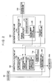
- Fig. 2 is an illustration showing an arrangement of the movement-estimating unit 600 and the correction-calculating unit 700.
- the movement-estimating unit 600 includes an acceleration-estimating unit 310 and a frequency-estimating unit 610.
- the acceleration-estimating unit 310 includes a nominal model setting unit 311 in which a nominal model i.e. a frequency transfer function from the scanning vector commanding unit 220 to the probe of the scanning probe 130 is set, a position-estimating unit 314 that estimates the position of the scanning probe 130 based on the scanning vector command and the nominal model, and a second-order differentiating unit 315 for calculating the acceleration of the scanning probe 130 from the data value of the estimated position obtained by the position-estimating unit 314 using a second-order differential.
- a nominal model setting unit 311 in which a nominal model i.e. a frequency transfer function from the scanning vector commanding unit 220 to the probe of the scanning probe 130 is set
- a position-estimating unit 314 that estimates the position of the scanning probe 130 based on the scanning vector command and the nominal model
- a second-order differentiating unit 315 for calculating the acceleration of the scanning probe 130 from the data value of the estimated position obtained by the position-estimating unit 314 using a second-order differential.
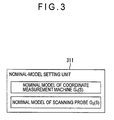
- Fig. 3 is an illustration showing an arrangement of the nominal-model setting unit.
- the nominal model setting unit 311 the nominal model as a frequency transfer function from the scanning vector commanding unit 220 to the probe (measurement portion) of the scanning probe 130 is set.
- a nominal model G 1 (s) of the coordinate measuring machine (nominal model of drive mechanism) and a nominal model G 2 (s) of the scanning probe are set in the nominal model 311.
- the nominal model of the scanning probe is provided for each type of the scanning probe 130 in preparation for exchanging the scanning probe 130, where the nominal model corresponding to the currently attached scanning probe 130 can be selected.
- the nominal model G N is obtained by a design data, an experiment value and the like.
- the nominal model G N is a first-order lag system
- the nominal model GN is represented by the following equation, where K represents gain and s represents Laplace operator.
- G N K ⁇ 1 1 + T ⁇ s
- the position-estimating unit 314 estimates the position of the scanning probe 130 based on the position command C (c x , c y , c z ) of the scanning vector command and the nominal model G N .
- the scanning vector command generated by the scanning vector commanding unit 220 is inputted every moment into the position-estimating unit 314.
- the estimated position E (e x , e y , e z ) of the scanning probe 130 is calculated based on the position command C (c x , c y , c z ) and the nominal model G N as follows.
- the estimated position E of the scanning probe 130 is represented by a product of the nominal model G N and the position command C.
- E G N ⁇ C
- the estimated position is represented after being decomposed in respective directions (Xm-axis direction, Ym-axis direction, Zm-axis direction), as follows.
- e x G N ⁇ c x
- e y G N ⁇ c y
- e z G N ⁇ c z
- the second-order differentiating unit 315 conducts second-order differential on the estimated position E (e x , e y , e z ) of the scanning probe 130 calculated by the position-estimating unit 314 to acquire the acceleration A (a x , a y , a z ) generated on the scanning probe 130 as an estimated movement state quantity.
- a t d 2 ⁇ E t d t 2
- the frequency-estimating unit 610 estimates the rotation frequency f when a circle is scan-measured with a constant angular velocity using the scanning probe 130.
- the acceleration A is calculated by the second-order differentiating unit 315
- the acceleration A (a x , a y , a z ) calculated by the second-order differentiating unit 315 is input into the frequency-estimating unit 610.
- the correction-calculating unit 700 includes: a correction-parameter storage 710 that stores a correction parameter indicating a relationship between the acceleration generated on the scanning probe 130 and the deformation of the coordinate measuring machine 110; a correction-amount calculating unit 720 that calculates a correction-amount D for correcting the sensor detection value based on the acceleration generated on the scanning probe 130; and a measurement data synthesizing unit 430 for synthesizing the calculated correction amount D and the sensor detection value to acquire the position of the workpiece surface S.
- the correction-parameter storage 710 stores a correction parameter P.
- the correction parameter P is a parameter that associates the deformation generated on the coordinate measuring machine 110 when the acceleration A works on the scanning probe 130 (specifically, the deformation generated on the column 123 and the spindle 124) with the acceleration A.
- the correction parameter P (p x , p y , p z ) is set for each axis direction, i.e. for Xm, Ym and Zm-axis directions.
- the correction-amount calculating unit 720 includes a gain correction-amount calculating unit 721 and a phase-difference correction-amount calculating unit 722.
- the acceleration A calculated by the movement-estimating unit 600 is input into the gain correction-amount calculating unit 721.
- the gain correction-amount calculating unit 721 calculates the correction amount D using the correction parameter P stored in the correction parameter storage 710 as follows.
- the phase-difference correction-amount calculating unit 722 calculates the phase difference of the command transmission between the respective axes generated during the circular movement on account of difference in the frequency transfer characteristics or drive gain for each drive-axes direction as a phase-difference correction-amount ⁇ .
- the measurement data synthesizing unit 430 synthesizes: the detection value (xm, ym, zm) of the drive sensor 140; the correction amount D (d x , d y , d z ) and the phase-difference correction-amount ⁇ calculated by the correction-amount calculating unit 720; and the detection value (x p , y p , z p ) by the probe sensor 134, to calculate the locus of the probe 132 of the scanning probe 130.
- the positional data of the workpiece surface S is obtained considering the reference pressing amount ⁇ r.
- the data synthesis by the measurement data synthesizing portion 430 will be described below.
- the detection value (x m , y m ) of the drive sensor 140 is represented using a predetermined phase ⁇ , as follows.
- the detection value after applying the calculated gain correction amount (d x , d y ) and the phase-difference correction-amount ⁇ is represented as follows, where x m ', y m ' represent the corrected detection value of the drive sensor.
- the surface position of the workpiece is determined at the position of the contact portion 132 acquired by synthesizing the corrected detection value (x m ', y m ') of the drive sensor 140 and the detection value of the probe sensor 134 after reflecting the reference pressing amount ⁇ r.
- the calculated positional data of the workpiece surface S is outputted to the form analyzer 500.
- the form analyzer 500 synthesizes the data to calculate the locus of the contact portion 132 and the profile data of the workpiece surface S.
- the form analyzer 500 conducts form analysis where the calculated profile data of the workpiece is compared with a design data to obtain errors, distortions and the like.
- the measuring condition is input in advance to actual measurement.
- the measuring condition includes sampling pitch, reference pressing amount ⁇ r, and the contour data of the workpiece.
- the nominal model G 1 (s) of the coordinate measuring machine and the nominal model G 2 (s) of the scanning probe are set in the nominal model setting section 311.
- a plurality of the nominal model is prepared for the scanning probe 130, among which a nominal model corresponding to the scanning probe 130 to be used is selected.
- the scanning vector command generated by the scanning vector commanding unit 220 is outputted to the drive control circuit 162.
- control signal is outputted from the drive control circuit 162 to the drive mechanism 120 to drive the drive mechanism 120.
- the scanning probe 130 is scan-moved along the workpiece surface S by the drive mechanism 120 while being pressed by the reference pressing amount ⁇ r relative to the workpiece surface S.
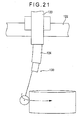
- Acceleration is generated during the scanning movement, which causes deformation on the spindle 124 of the coordinate measuring machine 110 (see, for instance, Fig. 21).
- the pressing amount is controlled at the reference pressing amount ⁇ r based on the probe counter value outputted from the probe counter 175 to the scanning vector command unit 220 during the scanning movement.
- the drive amount of the drive mechanism 120 while the scanning probe 130 scans the workpiece surface S is detected by the drive sensor 140, and the displacement of the stylus 131 is detected by the probe sensor 134.
- the sensor output of the drive sensor 140 is counted by the drive counter 171 and the sensor output of the probe sensor 134 is counted by the probe counter 175.
- the data counted by the counter unit 161 is acquired at the predetermined sampling pitch.
- the count value counted by the counter unit 161 (the drive counter 171 and the probe counter 175) is also outputted to the correction-calculating unit 700.
- the scanning vector command from the scanning vector commanding unit 220 is sent to the drive control circuit 162 and, simultaneously therewith, also to the movement-estimating unit 600.
- the scanning vector command is inputted into the position-estimating unit 314.
- the position-estimating unit 314 calculates an estimated position E(t) of the scanning probe 130 at the current time considering the frequency transfer characteristics based on the nominal model set in the nominal model setting unit 311 and the positional command of the scanning vector command.
- the estimated position E(t) (e x , e y , e z ) of the scanning probe 130 is calculated using the position command C (c x , c y , c z ) and the nominal model G N as follows.
- e x G N ⁇ c x
- e y G N ⁇ c y
- e z G N ⁇ c z
- the estimated position E calculated by the position-estimating unit 314 is inputted into the second-order differentiating unit 315.
- the second-order differentiating unit 315 calculates the acceleration A (a x , a y , a z ) generated on the scanning probe 130 at the present time using second-order differential on the calculated estimated position.
- a x e ⁇ x
- a y e ⁇ y
- a z e ⁇ z
- the acceleration A calculated by the second-order differentiating unit 315 is outputted to the correction-amount calculating unit 720 of the correction-calculating unit 700.
- the gain correction-amount calculating unit 721 calculates the correction-amount D per each axis for correcting the deformation caused on account of acceleration based on the inputted acceleration A and the correction parameters.
- the correction-amount D (d x , d y , d z ) of the detection value of the drive sensor when the acceleration A is generated on the scanning probe 130 is calculated as follows.
- d x p x ⁇ a x
- d y p y ⁇ a y
- d z p z ⁇ a z
- the acceleration A calculated by the second-order differentiating unit 315 is outputted to the frequency-estimating unit 610.
- the rotation frequency f of the circular movement is calculated at the frequency estimating unit 610 and the calculated rotation frequency f is outputted to the phase-difference correction-amount calculating unit 722.
- phase difference correction amount ⁇ as the function of the rotation frequency f is calculated by the phase-difference correction-amount calculating unit 722.
- the calculated phase-difference correction-amount ⁇ is outputted to the measurement data synthesizing unit 430 together with the gain correction-amount D (d x , d y , d z ) calculated by the gain correction-amount calculating unit 721.
- the measurement data synthesizing unit 430 synthesizes: the detection value (x m , y m , z m ) of the drive sensor 140; the calculated correction amount D (d x , d y , d z ) and the phase-difference correction-amount ⁇ ; and the detection value (x p , y p , z p ) by the probe sensor 134, to calculate the position of the probe 132.
- the workpiece surface S is set at a position considering the predetermined reference pressing amount ⁇ r relative to the position of the probe 132.
- the obtained surface data of the workpiece W is sequentially sent to the form analyzer 500 to obtain the profile data of the workpiece surface S.
- a full circle (360°) data has to be acquired when the scanning velocity (or rotation frequency) shows a constant value as shown in Fig 4.
- the rotation frequency f is calculated from the estimated acceleration per each moment and the correction amount can be calculated based on the calculated rotation frequency f in the first embodiment, all of the acquired data can be appropriately corrected and the measurement data can be acquired without waiting for the scanning velocity (i.e. rotation frequency) to reach a constant level.
- the data acquired in an area where the scanning velocity (or rotation frequency) is changing can be accurately corrected as shown in Fig. 5.
- the first modification is substantially the same as the above-described first embodiment, which is characterized by calculation of the correction parameters
- the correction amount calculated by the correction-amount calculating unit 700 of the first embodiment includes the gain correction-amount by the gain correction-amount calculating unit 721 and the phase-difference-correction amount by the phase-difference correction-amount calculating unit 722.
- the acceleration a x in Xm-axis direction can be represented as follows, where the scanning velocity is V and radius is Rs.
- a x V 2 Rs ⁇ x - x 0 Rs
- deformation d x in Xm-axis direction is expressed with reference to the acceleration a x generated in Xm-axis direction as follows while taking square term of the measured coordinates into consideration.
- d x V 2 R s ⁇ x - x 0 R s ⁇ ⁇ 1 ⁇ x 2 + ⁇ 2 ⁇ x + ⁇ 3
- the equation can be transformed as follows adding the correction amount d y in Ym-axis direction and the correction amount d z in Zm-axis direction.
- d x d y d z V 2 R s ⁇ ⁇ 1 ⁇ x - x 0 ⁇ 2 ⁇ x - x 0 ⁇ 3 ⁇ x - x 0 ⁇ 4 ⁇ x - x 0 ⁇ 5 ⁇ x - x 0 ⁇ 6 ⁇ x - x 0 ⁇ 7 ⁇ x - x 0 ⁇ 8 ⁇ x - x 0 ⁇ 9 ⁇ x - x 0 ⁇ x 2 x 1
- the correction factor can be represented as follows.
- the correction parameters can be acquired as a coefficient of a fitting curve after calculating errors by actual experiments.
- calibration test in order to acquire the calibration data is conducted as a scanning measurement of a circle while placing a standard gauge at a plurality of different positions at a plurality of scanning velocity (or acceleration).
- the scanning measurement of a circle is conducted at a plurality of locations P 1 to P 5 shown in Fig. 6.
- Fig. 6 five points having the same Ym coordinate and different Xm coordinate is selected in Fig. 6 for the convenience of explanation. However, it is preferable to distribute the points evenly across Xm, Ym and Zm coordinates system within the measurement area of the measuring system 100.
- Figs. 7 and 8 are illustrations showing a relationship between a scanning velocity V and a radius decrease (radius error ⁇ R) when the circle is scan-measured at respective points P 1 to P 5 .
- the vertical axis of Fig. 7 shows the maximum amount of the radius error ⁇ R in Xm-axis direction and the vertical axis of Fig. 8 shows the maximum amount of the radius error ⁇ R in Ym-axis direction.
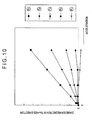
- Figs. 9 and 10 are graphs showing the relationship between the radius decrease (radius error ⁇ R) and the acceleration by converting the scanning velocity of Figs. 7 and 8 into acceleration.
- the vertical axis of Fig. 9 shows the maximum amount of the radius error ⁇ R in Xm-axis direction as in Fig. 7.
- the vertical axis of Fig. 10 shows the maximum amount of the radius error ⁇ R in Ym-axis direction as in Fig 8.
- the measurement radius decrease (radius error ⁇ R) interrelates to the power (e.g. square) of scanning velocity.
- Figs. 11 and 12 are illustrations showing a relationship between a measured position and measurement radius decrease (radius error ⁇ R).
- the vertical axis represents a normalized value ( ⁇ R/a) obtained by dividing measurement radius decrease (radius error ⁇ R) by acceleration.
- the vertical axis of Fig. 11 is a value ( ⁇ Rx/a) dividing the maximum amount ( ⁇ Rx) of the radius error ⁇ R in Xm-axis direction by acceleration.
- the vertical axis of Fig. 12 is a value ( ⁇ Ry/a) dividing the maximum amount ( ⁇ Ry) of the radius error ⁇ R in Ym-axis direction by acceleration.
- measurement diameter decrease ( ⁇ Ry) in Ym-axis direction is influenced by the difference of the measured position in Xm-axis direction and is quadratically interrelated to the Xm coordinate.
- the error (d x , d y , d z ) when the standard gauge is measured at different scanning velocities (or acceleration) at positions with different Xm, Ym and Zm coordinates is assigned to equation.
- the obtained gain-correction parameters are stored in the correction-parameter storage 710.
- phase difference in command transfer is generated for each axis during the circular movement.
- the phase difference is set as the phase-difference correction-amount ⁇ and is acquired as a function of the rotation frequency f of the circular movement.
- phase-difference correction-amount ⁇ is a function of the rotation frequency f, which is represented as polynomial equation of the rotation frequency f.
- Fig. 13 shows the result of scanning measurement of a circle at a plurality of locations P 1 to P 5 shown in Fig. 6.
- Fig. 13 the generated phase difference ⁇ is plotted in vertical axis and the rotation frequency f of the circular movement is plotted in horizontal axis.
- phase difference ⁇ between Ym-axis direction and Xm-axis direction depends on rotation frequency f of the circular movement, and, though less influenced, also depends on measured position.
- phase difference ⁇ is represented as follows.
- the correction parameters thus obtained is used to calculate the gain correction-amount and the phase-difference correction amount ⁇ as described in the first embodiment.
- the measurement data can be corrected using the gain correction-amount and the phase-difference correction amount as discussed in the first embodiment.
- the second modification is substantially the same as the above-described first modification, which is characterized by calculation of the correction parameters for setting the correction parameters.
- the second modification uses an equation supposing that the deformation of the spindle 124 interrelates to the rotation frequency f.
- the correction amount includes gain correction-amount and phase-difference correction amount.
- the correction parameters for calculating the phase-difference correction amount are set, the same process as the first modification can be employed and the detailed explanation thereof will not be mentioned below.
- the acceleration A is represented by the following equation using the rotation frequency f based on the relationship between the radius Rs of the circular movement and the angular velocity ⁇ .
- of the rotary frequency characteristics can be represented as follows.
- 1 - k .
- Rs 1 - k ( 2 ⁇ ⁇ ⁇ f ⁇ ) 2
- the correction parameters k defining the relationship between the gain and the rotation frequency f are obtained by a designed value or an empirical value based on the above relational expressions.
- is calculated respectively in Xm-axis direction and Ym-axis direction.
- the Xm-axis gain is calculated as
- and Ym-axis gain is calculated as
- ) and the phase-difference correction amount ⁇ is corrected as follows.
- the detection value by the drive sensor 140 is (x m , y m ); the central coordinate of the circular movement is set as (x0, y0); and the radius of the circle is represented as Rs
- ) and the phase-difference ⁇ is represented as follows, where x m ', y m ' represents the corrected detection value of the drive sensor.
- the surface position of the workpiece is determined at the position of the contact portion 132 acquired by synthesizing the corrected detection value (x m ', y m ') of the drive sensor 140 and the detection value of the probe sensor 134 after reflecting the predetermined reference pressing amount ⁇ r.
- the correction parameters for calculating the gain correction-amount can be obtained by the process shown in the second modification.
- the measurement data can be corrected using the gain correction-amount and the phase-difference compensation amount.
- the third modification is substantially the same as the above-described second modification, which is characterized by calculation of the correction parameters in setting the correction parameters.
- the correction equation is established on the basis that the deformation is expressed by a theoretical equation that interrelates to the rotation frequency f.
- the correction equation is established supposing that the deformation is expressed by a polynomial equation using the rotation frequency f.
- in Ym-axis direction is expressed as a polynomial equation related to rotation frequency f of the circular movement during scanning measurement of a circle.
- standard gauges are placed at a plurality of different positions and a circle is scan-measured at a plurality of scanning velocity.
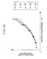
- Fig. 14 is a graph in which rotation frequency during the scan-measurement is plotted in horizontal axis and maximum amount of radius error ⁇ R in Xm-axis direction is plotted in vertical direction.
- Fig. 15 is a graph in which rotation frequency during the scan-measurement is plotted in horizontal axis and maximum amount of radius error ⁇ R in Ym-axis direction is plotted in vertical direction.
- the measured position is the same as the first modification, which is the result of scanning measurement of a circle at a plurality of locations P 1 to P 5 shown in Fig. 6.
- the relationship between the rotation frequency of the scanning measurement and the measurement error can be fitted by a second-order polynomial equation of the rotation frequency f.
- in Ym-axis direction can be represented using a predetermined coefficient as follows.
- ⁇ 2 ⁇ f 2 + ⁇ 1 ⁇ f + 1
- ⁇ 2 ⁇ f 2 + ⁇ 1 ⁇ f + 1
- the deformation changes in accordance with the measured position and therefore is a function of the measured position.
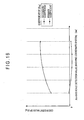
- Fig. 16 is a graph showing the relationship between the coefficient of the gain error
- Fig. 17 is a graph showing the relationship between the coefficient of the gain error
- the coefficients ⁇ 2 , ⁇ 1 , ⁇ 2 , ⁇ 1 are functions of measured position, which can be represented as follows.
- Correction parameters ⁇ 1 , ⁇ 2 , ⁇ 2 , ⁇ 1 indicating the relationship between the gain and the rotation frequency are determined based on the above relational equations.
- the obtained gain-correction parameters are stored in the correction-parameter storage 710.
- the correction parameters for calculating the gain correction-amount can be calculated by the above third modification.
- the measurement data can be corrected using the gain correction-amount and the phase-difference correction-amount.
- the basic arrangement of the second embodiment is substantially the same as the above-described first embodiment. What is specific about the second embodiment is the provision of an estimation-judging unit 800 that judges the accuracy of the acceleration estimation by comparing an estimated acceleration value calculated by the movement-estimating unit 600 with actual acceleration.
- Fig. 18 is an illustration showing an arrangement of a movement-estimating unit, correction-calculating unit and an estimation-judging unit of the second embodiment.
- the estimation-judging unit 800 includes: an actual acceleration calculating unit 810 for calculating an actual acceleration based on the measured value of the coordinates detected by the counter unit 161; a difference-calculating unit 820 that compares an estimated acceleration value calculated by the movement-estimating unit 600 to the actual acceleration calculated by the actual acceleration calculating unit 810; and a judging unit 830 that compares a difference value calculated by the difference-calculating unit 820 with a predetermined threshold value to judge the accuracy of the estimated acceleration value.
- the counter value from the drive counter 171 is input into the actual acceleration calculating unit 810.
- the actual acceleration calculating unit 810 conducts second-order differential on the counter value from the drive counter 171 to calculate the actual acceleration.
- the calculated actual acceleration is outputted to the difference-calculating unit 820.
- the estimated acceleration value from the second-order differentiating unit 315 and the actual acceleration from the actual acceleration calculating unit 810 are input to the difference-calculating unit 820.
- the difference-calculating unit 820 calculates difference value ⁇ a by subtracting the actual acceleration a R from the estimated acceleration a.
- the calculated difference value ⁇ a is outputted to the judging unit 830.
- a threshold value is set in advance in the determining unit 830.
- the threshold value is a value for judging whether the difference value ⁇ a between the estimated acceleration a and the actual acceleration a R is excessively large to hinder normal function of the acceleration estimation, thus making the correction based on estimated acceleration impossible.
- the difference value ⁇ a calculated by the difference calculating unit 820 is input into the judging unit 830 and the judging unit 830 compares the difference value ⁇ a with the threshold value.
- the correction calculation by the correction-amount calculating unit 700 is stopped.
- the estimation-judging unit 800 since the estimation-judging unit 800 is provided, the accuracy of the acceleration estimation by the movement-estimating unit 600 can be judged.
- the surface-profile measuring instrument of the present invention is not limited solely to the above embodiments and modifications, but includes various modifications as long as an object of the present invention can be achieved.
- the scanning velocity may be used as the estimated movement state quantity instead of acceleration.
- the relationship between the scanning velocity and the correction amount may be calculated so that the correction calculation is possible based on the scanning velocity.
- a nominal model for directly calculating acceleration from the positional command of the scanning vector may be set.
- the estimation-judging unit 800 may include a low-pass filter therein and high-frequency noise may be cut from the actual acceleration obtained by the actual acceleration calculating unit 810. Accordingly, judgment error on account of the high-frequency noise can be prevented.
Landscapes
- Physics & Mathematics (AREA)
- General Physics & Mathematics (AREA)
- A Measuring Device Byusing Mechanical Method (AREA)
- Length Measuring Devices With Unspecified Measuring Means (AREA)
Applications Claiming Priority (2)
| Application Number | Priority Date | Filing Date | Title |
|---|---|---|---|
| JP2006243376 | 2006-09-07 | ||
| JP2007216380A JP5189806B2 (ja) | 2006-09-07 | 2007-08-22 | 表面形状測定装置 |
Publications (3)
| Publication Number | Publication Date |
|---|---|
| EP1898428A2 true EP1898428A2 (de) | 2008-03-12 |
| EP1898428A3 EP1898428A3 (de) | 2014-01-15 |
| EP1898428B1 EP1898428B1 (de) | 2017-08-30 |
Family
ID=38626376
Family Applications (1)
| Application Number | Title | Priority Date | Filing Date |
|---|---|---|---|
| EP07017603.7A Not-in-force EP1898428B1 (de) | 2006-09-07 | 2007-09-07 | Messinstrument für Oberflächenprofile |
Country Status (4)
| Country | Link |
|---|---|
| US (1) | US7660688B2 (de) |
| EP (1) | EP1898428B1 (de) |
| JP (1) | JP5189806B2 (de) |
| CN (1) | CN101140161B (de) |
Cited By (1)
| Publication number | Priority date | Publication date | Assignee | Title |
|---|---|---|---|---|
| JP2016090434A (ja) * | 2014-11-06 | 2016-05-23 | 株式会社ミツトヨ | 形状測定装置、及び形状測定方法 |
Families Citing this family (33)
| Publication number | Priority date | Publication date | Assignee | Title |
|---|---|---|---|---|
| JP5192283B2 (ja) | 2008-05-13 | 2013-05-08 | 株式会社ミツトヨ | 三次元測定機 |
| JP5297818B2 (ja) | 2009-01-06 | 2013-09-25 | 株式会社ミツトヨ | 三次元測定機 |
| EP2219010A1 (de) * | 2009-02-11 | 2010-08-18 | Leica Geosystems AG | Koordinatenmessmaschine und Verfahren zum Kompensieren von Fehlern in einer Koordinatenmessmaschine |
| JP5371532B2 (ja) | 2009-04-23 | 2013-12-18 | 株式会社ミツトヨ | 三次元測定機 |
| JP5272248B2 (ja) | 2009-05-08 | 2013-08-28 | 株式会社ミツトヨ | 表面性状測定装置、表面性状測定方法、及びプログラム |
| CN101614517B (zh) * | 2009-08-13 | 2010-11-17 | 沈阳飞机工业(集团)有限公司 | 平面表面波纹度测量装置 |
| DE102009049534A1 (de) * | 2009-10-06 | 2011-04-07 | Carl Zeiss Industrielle Messtechnik Gmbh | Koordinatenmessgerät mit Lageänderungssensoren |
| GB201003363D0 (en) * | 2010-03-01 | 2010-04-14 | Renishaw Plc | Measurement method and apparatus |
| JP5557620B2 (ja) * | 2010-06-29 | 2014-07-23 | 株式会社ミツトヨ | 形状測定装置 |
| JP2012018117A (ja) * | 2010-07-09 | 2012-01-26 | Mitsutoyo Corp | 形状測定装置 |
| JP5612386B2 (ja) | 2010-07-23 | 2014-10-22 | 株式会社ミツトヨ | 形状測定装置 |
| EP2634530B1 (de) * | 2010-10-27 | 2022-05-04 | Nikon Corporation | Formmessvorrichtung, formmessverfahren, und strukturherstellungsverfahren |
| US20130262213A1 (en) * | 2012-04-03 | 2013-10-03 | Prashant Jamkhedkar | Systems, Methods, And Computer Program Products Providing Payment With Non-Traditional Sources Of Value |
| JP6030339B2 (ja) * | 2012-05-17 | 2016-11-24 | 株式会社ミツトヨ | 形状測定装置 |
| CN102799758B (zh) * | 2012-06-12 | 2016-03-02 | 联想(北京)有限公司 | 一种信息获取方法及电子设备 |
| DE102013106005B4 (de) | 2012-06-12 | 2018-12-06 | Lenovo (Beijing) Co., Ltd. | Informationssteuerverfahren für einen Würfel und elektronische Vorrichtung, die ein Würfel ist |
| CN102902402B (zh) * | 2012-06-29 | 2015-06-24 | 联想(北京)有限公司 | 电子装置、电子设备和辨别电子装置的表面的方法 |
| JP6154605B2 (ja) * | 2012-09-04 | 2017-06-28 | 株式会社ミツトヨ | 形状測定装置及び形状測定誤差の補正方法 |
| JP6114010B2 (ja) * | 2012-11-14 | 2017-04-12 | 株式会社ミツトヨ | 形状測定装置及び形状測定誤差の補正方法 |
| DE112014002974T5 (de) | 2013-06-24 | 2016-06-09 | Dcg Systems, Inc. | Sondenbasierendes Datensammelsystem mit adaptiver Sonden-Untersuchung gesteuert durch lokale Eigenschaften der Probe |
| KR101510143B1 (ko) * | 2013-11-06 | 2015-04-08 | 주식회사 고영테크놀러지 | 기판 검사 시의 측정영역 보상 방법 |
| CN103808251B (zh) * | 2014-02-14 | 2015-07-08 | 哈尔滨工业大学 | 航空发动机转子装配方法与装置 |
| JP6254451B2 (ja) * | 2014-02-19 | 2017-12-27 | 株式会社ミツトヨ | 形状測定装置及び形状測定誤差の補正方法 |
| WO2015200724A1 (en) | 2014-06-25 | 2015-12-30 | Dcg Systems, Inc. | Apparatus and method for nanoprobing of electronic devices |
| JP6448242B2 (ja) * | 2014-07-18 | 2019-01-09 | 株式会社ミツトヨ | 形状測定装置の測定誤差の補正方法及び形状測定装置 |
| JP6838056B2 (ja) * | 2016-05-02 | 2021-03-03 | 住友電工ハードメタル株式会社 | 切れ刃の軌道を補正する方法、記録媒体およびプログラム |
| JP6295299B2 (ja) * | 2016-08-26 | 2018-03-14 | 株式会社ミツトヨ | 座標補正方法及び三次元測定装置 |
| DK3367053T3 (da) * | 2017-02-27 | 2021-05-10 | Kulzer & Co Gmbh | 3d-scanner med gyroskopsensor |
| JP6738883B2 (ja) * | 2018-11-28 | 2020-08-12 | 株式会社ミツトヨ | プローブユニット及び測定システム |
| US11499817B2 (en) | 2020-05-29 | 2022-11-15 | Mitutoyo Corporation | Coordinate measuring machine with vision probe for performing points-from-focus type measurement operations |
| US11328409B2 (en) | 2020-09-30 | 2022-05-10 | Mitutoyo Corporation | System and method utilizing multi-point autofocus to align an optical axis of an optical assembly portion to be normal to a workpiece surface |
| CN113095195B (zh) * | 2021-04-03 | 2023-04-07 | 西北工业大学 | 一种基于表面形貌自特征的零件唯一识别方法 |
| US11635291B2 (en) | 2021-04-30 | 2023-04-25 | Mitutoyo Corporation | Workpiece holder for utilization in metrology system for measuring workpiece in different orientations |
Family Cites Families (25)
| Publication number | Priority date | Publication date | Assignee | Title |
|---|---|---|---|---|
| US5189806A (en) * | 1988-12-19 | 1993-03-02 | Renishaw Plc | Method of and apparatus for scanning the surface of a workpiece |
| DE4245012B4 (de) * | 1992-04-14 | 2004-09-23 | Carl Zeiss | Verfahren zur Messung von Formelementen auf einem Koordinatenmeßgerät |
| JP2628523B2 (ja) | 1992-05-14 | 1997-07-09 | 株式会社 ミツトヨ | 表面形状測定用トレーサ |
| EP0684447B1 (de) * | 1994-05-27 | 2003-09-17 | Carl Zeiss | Koordinatenmessung an Werkstücken mit einer Korrektur des durch die Messkraft abhängigen Biegeverhaltens des Koordinatenmessgerätes |
| DE59510879D1 (de) * | 1994-05-27 | 2004-04-29 | Zeiss Carl | Koordinatenmessung an Werkstücken mit Korrekturen von Beschleunigungen |
| US5832416A (en) * | 1995-09-01 | 1998-11-03 | Brown & Sharpe Manufacturing Company | Calibration system for coordinate measuring machine |
| DE19539148A1 (de) * | 1995-10-20 | 1997-04-24 | Zeiss Carl Fa | Verfahren zur Koordinatenmessung von Werkstücken |
| EP0849654B1 (de) * | 1996-12-21 | 2004-04-28 | Carl Zeiss | Verfahren zur Steuerung von Koordinatenmessgeräten und Koordinatenmessgerät |
| DE69814198T2 (de) * | 1997-02-10 | 2004-04-08 | Mitutoyo Corp., Kawasaki | Messverfahren und Messinstrument mit Triggersonde |
| DE19712029A1 (de) * | 1997-03-21 | 1998-09-24 | Zeiss Carl Fa | Verfahren zur Steuerung von Koordinatenmeßgeräten nach Solldaten |
| JP2000199710A (ja) * | 1999-01-06 | 2000-07-18 | Mitsutoyo Corp | タッチ信号プロ―ブの接触部位検出構造 |
| US6526364B2 (en) * | 2000-01-19 | 2003-02-25 | Mitutoyo Corporation | Method and apparatus for measuring roundness |
| JP3516630B2 (ja) * | 2000-03-29 | 2004-04-05 | 株式会社ミツトヨ | 形状測定機及び形状測定方法 |
| DE50115041D1 (de) * | 2000-05-23 | 2009-09-24 | Zeiss Ind Messtechnik Gmbh | Korrekturverfahren für Koordinatenmessgeräte |
| GB0215478D0 (en) * | 2002-07-04 | 2002-08-14 | Renishaw Plc | Method of scanning a calibrating system |
| JP4009152B2 (ja) * | 2002-07-09 | 2007-11-14 | 株式会社ミツトヨ | 表面形状測定装置および表面形状測定方法 |
| US6895359B2 (en) * | 2002-11-25 | 2005-05-17 | Mitutoyo Corporation | Workpiece coordinate system origin setting method, workpiece coordinate system origin setting program and workpiece coordinate system origin setting device of a surface property measuring machine |
| WO2004106854A1 (de) * | 2003-05-28 | 2004-12-09 | Carl Zeiss Industrielle Messtechnik Gmbh | Verfahren zur kalibrierung eines tasters |
| JP4259961B2 (ja) | 2003-09-03 | 2009-04-30 | 株式会社ミツトヨ | 制御対象モデルの物理特性算出式導出方法、制御対象モデルの物理特性算出方法 |
| US7376261B2 (en) * | 2003-11-25 | 2008-05-20 | Mitutoyo Corporation | Surface scan measuring device and method of forming compensation table for scanning probe |
| JP4695374B2 (ja) | 2003-11-25 | 2011-06-08 | 株式会社ミツトヨ | 表面倣い測定装置および倣いプローブの補正テーブル作成方法 |
| DE102004011728A1 (de) * | 2004-03-05 | 2005-09-22 | Carl Zeiss Industrielle Messtechnik Gmbh | Tastkopf für ein Koordinatenmessgerät |
| JP4782990B2 (ja) * | 2004-05-31 | 2011-09-28 | 株式会社ミツトヨ | 表面倣い測定装置、表面倣い測定方法、表面倣い測定プログラムおよび記録媒体 |
| JP4909548B2 (ja) * | 2005-09-01 | 2012-04-04 | 株式会社ミツトヨ | 表面形状測定装置 |
| JP5192196B2 (ja) * | 2007-08-03 | 2013-05-08 | 株式会社ミツトヨ | 表面形状測定装置 |
-
2007
- 2007-08-22 JP JP2007216380A patent/JP5189806B2/ja not_active Expired - Fee Related
- 2007-09-06 US US11/896,903 patent/US7660688B2/en active Active
- 2007-09-07 CN CN2007101490671A patent/CN101140161B/zh not_active Expired - Fee Related
- 2007-09-07 EP EP07017603.7A patent/EP1898428B1/de not_active Not-in-force
Cited By (1)
| Publication number | Priority date | Publication date | Assignee | Title |
|---|---|---|---|---|
| JP2016090434A (ja) * | 2014-11-06 | 2016-05-23 | 株式会社ミツトヨ | 形状測定装置、及び形状測定方法 |
Also Published As
| Publication number | Publication date |
|---|---|
| EP1898428B1 (de) | 2017-08-30 |
| US7660688B2 (en) | 2010-02-09 |
| JP2008089578A (ja) | 2008-04-17 |
| EP1898428A3 (de) | 2014-01-15 |
| US20080065341A1 (en) | 2008-03-13 |
| CN101140161A (zh) | 2008-03-12 |
| CN101140161B (zh) | 2012-07-18 |
| JP5189806B2 (ja) | 2013-04-24 |
Similar Documents
| Publication | Publication Date | Title |
|---|---|---|
| EP1898428B1 (de) | Messinstrument für Oberflächenprofile | |
| JP5192196B2 (ja) | 表面形状測定装置 | |
| EP0858015B1 (de) | Messverfahren und Messinstrument mit Triggersonde | |
| EP2664891B1 (de) | Formmessvorrichtung | |
| US8786243B2 (en) | Method and device for preparing error map and numerically controlled machine tool having error map preparation function | |
| EP2204636B1 (de) | Koordinatenmessmaschine | |
| JP5022544B2 (ja) | 座標測定器の修正方法および座標測定器 | |
| US7286949B2 (en) | Method of error correction | |
| US7376261B2 (en) | Surface scan measuring device and method of forming compensation table for scanning probe | |
| EP2013571B1 (de) | Verfahren zur fehlerkorrektur | |
| EP1792139B1 (de) | Verwendung von oberflächenmesssonden | |
| EP2149775B1 (de) | Profilmessinstrument und Profilmessverfahren | |
| US6484571B1 (en) | Surface configuration measuring method | |
| JP4618616B2 (ja) | 数値制御装置 | |
| JP6564171B2 (ja) | 形状測定装置、及び形状測定方法 | |
| US20250028296A1 (en) | Computation device, machining system, and correction method | |
| JPS6318684B2 (de) | ||
| JPH03118412A (ja) | 形状測定機の測定方法 |
Legal Events
| Date | Code | Title | Description |
|---|---|---|---|
| PUAI | Public reference made under article 153(3) epc to a published international application that has entered the european phase |
Free format text: ORIGINAL CODE: 0009012 |
|
| AK | Designated contracting states |
Kind code of ref document: A2 Designated state(s): AT BE BG CH CY CZ DE DK EE ES FI FR GB GR HU IE IS IT LI LT LU LV MC MT NL PL PT RO SE SI SK TR |
|
| AX | Request for extension of the european patent |
Extension state: AL BA HR MK YU |
|
| PUAL | Search report despatched |
Free format text: ORIGINAL CODE: 0009013 |
|
| AK | Designated contracting states |
Kind code of ref document: A3 Designated state(s): AT BE BG CH CY CZ DE DK EE ES FI FR GB GR HU IE IS IT LI LT LU LV MC MT NL PL PT RO SE SI SK TR |
|
| AX | Request for extension of the european patent |
Extension state: AL BA HR MK RS |
|
| 17P | Request for examination filed |
Effective date: 20140715 |
|
| RBV | Designated contracting states (corrected) |
Designated state(s): AT BE BG CH CY CZ DE DK EE ES FI FR GB GR HU IE IS IT LI LT LU LV MC MT NL PL PT RO SE SI SK TR |
|
| AKX | Designation fees paid |
Designated state(s): AT BE BG CH CY CZ DE DK EE ES FI FR GB GR HU IE IS IT LI LT LU LV MC MT NL PL PT RO SE SI SK TR |
|
| REG | Reference to a national code |
Ref country code: DE Ref legal event code: R079 Ref document number: 602007052150 Country of ref document: DE Free format text: PREVIOUS MAIN CLASS: G12B0021200000 Ipc: G01B0021040000 |
|
| GRAP | Despatch of communication of intention to grant a patent |
Free format text: ORIGINAL CODE: EPIDOSNIGR1 |
|
| RIC1 | Information provided on ipc code assigned before grant |
Ipc: G01B 21/04 20060101AFI20170228BHEP |
|
| INTG | Intention to grant announced |
Effective date: 20170317 |
|
| GRAS | Grant fee paid |
Free format text: ORIGINAL CODE: EPIDOSNIGR3 |
|
| GRAA | (expected) grant |
Free format text: ORIGINAL CODE: 0009210 |
|
| AK | Designated contracting states |
Kind code of ref document: B1 Designated state(s): AT BE BG CH CY CZ DE DK EE ES FI FR GB GR HU IE IS IT LI LT LU LV MC MT NL PL PT RO SE SI SK TR |
|
| REG | Reference to a national code |
Ref country code: GB Ref legal event code: FG4D |
|
| REG | Reference to a national code |
Ref country code: CH Ref legal event code: EP |
|
| REG | Reference to a national code |
Ref country code: AT Ref legal event code: REF Ref document number: 923984 Country of ref document: AT Kind code of ref document: T Effective date: 20170915 |
|
| REG | Reference to a national code |
Ref country code: IE Ref legal event code: FG4D |
|
| REG | Reference to a national code |
Ref country code: FR Ref legal event code: PLFP Year of fee payment: 11 |
|
| REG | Reference to a national code |
Ref country code: DE Ref legal event code: R096 Ref document number: 602007052150 Country of ref document: DE |
|
| REG | Reference to a national code |
Ref country code: NL Ref legal event code: MP Effective date: 20170830 |
|
| REG | Reference to a national code |
Ref country code: LT Ref legal event code: MG4D |
|
| REG | Reference to a national code |
Ref country code: AT Ref legal event code: MK05 Ref document number: 923984 Country of ref document: AT Kind code of ref document: T Effective date: 20170830 |
|
| PG25 | Lapsed in a contracting state [announced via postgrant information from national office to epo] |
Ref country code: SE Free format text: LAPSE BECAUSE OF FAILURE TO SUBMIT A TRANSLATION OF THE DESCRIPTION OR TO PAY THE FEE WITHIN THE PRESCRIBED TIME-LIMIT Effective date: 20170830 Ref country code: LT Free format text: LAPSE BECAUSE OF FAILURE TO SUBMIT A TRANSLATION OF THE DESCRIPTION OR TO PAY THE FEE WITHIN THE PRESCRIBED TIME-LIMIT Effective date: 20170830 Ref country code: AT Free format text: LAPSE BECAUSE OF FAILURE TO SUBMIT A TRANSLATION OF THE DESCRIPTION OR TO PAY THE FEE WITHIN THE PRESCRIBED TIME-LIMIT Effective date: 20170830 Ref country code: FI Free format text: LAPSE BECAUSE OF FAILURE TO SUBMIT A TRANSLATION OF THE DESCRIPTION OR TO PAY THE FEE WITHIN THE PRESCRIBED TIME-LIMIT Effective date: 20170830 |
|
| PG25 | Lapsed in a contracting state [announced via postgrant information from national office to epo] |
Ref country code: LV Free format text: LAPSE BECAUSE OF FAILURE TO SUBMIT A TRANSLATION OF THE DESCRIPTION OR TO PAY THE FEE WITHIN THE PRESCRIBED TIME-LIMIT Effective date: 20170830 Ref country code: ES Free format text: LAPSE BECAUSE OF FAILURE TO SUBMIT A TRANSLATION OF THE DESCRIPTION OR TO PAY THE FEE WITHIN THE PRESCRIBED TIME-LIMIT Effective date: 20170830 Ref country code: GR Free format text: LAPSE BECAUSE OF FAILURE TO SUBMIT A TRANSLATION OF THE DESCRIPTION OR TO PAY THE FEE WITHIN THE PRESCRIBED TIME-LIMIT Effective date: 20171201 Ref country code: IS Free format text: LAPSE BECAUSE OF FAILURE TO SUBMIT A TRANSLATION OF THE DESCRIPTION OR TO PAY THE FEE WITHIN THE PRESCRIBED TIME-LIMIT Effective date: 20171230 Ref country code: BG Free format text: LAPSE BECAUSE OF FAILURE TO SUBMIT A TRANSLATION OF THE DESCRIPTION OR TO PAY THE FEE WITHIN THE PRESCRIBED TIME-LIMIT Effective date: 20171130 |
|
| PG25 | Lapsed in a contracting state [announced via postgrant information from national office to epo] |
Ref country code: NL Free format text: LAPSE BECAUSE OF FAILURE TO SUBMIT A TRANSLATION OF THE DESCRIPTION OR TO PAY THE FEE WITHIN THE PRESCRIBED TIME-LIMIT Effective date: 20170830 |
|
| PG25 | Lapsed in a contracting state [announced via postgrant information from national office to epo] |
Ref country code: DK Free format text: LAPSE BECAUSE OF FAILURE TO SUBMIT A TRANSLATION OF THE DESCRIPTION OR TO PAY THE FEE WITHIN THE PRESCRIBED TIME-LIMIT Effective date: 20170830 Ref country code: CZ Free format text: LAPSE BECAUSE OF FAILURE TO SUBMIT A TRANSLATION OF THE DESCRIPTION OR TO PAY THE FEE WITHIN THE PRESCRIBED TIME-LIMIT Effective date: 20170830 Ref country code: RO Free format text: LAPSE BECAUSE OF FAILURE TO SUBMIT A TRANSLATION OF THE DESCRIPTION OR TO PAY THE FEE WITHIN THE PRESCRIBED TIME-LIMIT Effective date: 20170830 Ref country code: PL Free format text: LAPSE BECAUSE OF FAILURE TO SUBMIT A TRANSLATION OF THE DESCRIPTION OR TO PAY THE FEE WITHIN THE PRESCRIBED TIME-LIMIT Effective date: 20170830 |
|
| REG | Reference to a national code |
Ref country code: CH Ref legal event code: PL |
|
| PG25 | Lapsed in a contracting state [announced via postgrant information from national office to epo] |
Ref country code: IT Free format text: LAPSE BECAUSE OF FAILURE TO SUBMIT A TRANSLATION OF THE DESCRIPTION OR TO PAY THE FEE WITHIN THE PRESCRIBED TIME-LIMIT Effective date: 20170830 Ref country code: MC Free format text: LAPSE BECAUSE OF FAILURE TO SUBMIT A TRANSLATION OF THE DESCRIPTION OR TO PAY THE FEE WITHIN THE PRESCRIBED TIME-LIMIT Effective date: 20170830 Ref country code: SK Free format text: LAPSE BECAUSE OF FAILURE TO SUBMIT A TRANSLATION OF THE DESCRIPTION OR TO PAY THE FEE WITHIN THE PRESCRIBED TIME-LIMIT Effective date: 20170830 Ref country code: EE Free format text: LAPSE BECAUSE OF FAILURE TO SUBMIT A TRANSLATION OF THE DESCRIPTION OR TO PAY THE FEE WITHIN THE PRESCRIBED TIME-LIMIT Effective date: 20170830 |
|
| REG | Reference to a national code |
Ref country code: DE Ref legal event code: R097 Ref document number: 602007052150 Country of ref document: DE |
|
| REG | Reference to a national code |
Ref country code: IE Ref legal event code: MM4A |
|
| REG | Reference to a national code |
Ref country code: BE Ref legal event code: MM Effective date: 20170930 |
|
| PG25 | Lapsed in a contracting state [announced via postgrant information from national office to epo] |
Ref country code: LU Free format text: LAPSE BECAUSE OF NON-PAYMENT OF DUE FEES Effective date: 20170907 |
|
| PLBE | No opposition filed within time limit |
Free format text: ORIGINAL CODE: 0009261 |
|
| STAA | Information on the status of an ep patent application or granted ep patent |
Free format text: STATUS: NO OPPOSITION FILED WITHIN TIME LIMIT |
|
| PG25 | Lapsed in a contracting state [announced via postgrant information from national office to epo] |
Ref country code: LI Free format text: LAPSE BECAUSE OF NON-PAYMENT OF DUE FEES Effective date: 20170930 Ref country code: CH Free format text: LAPSE BECAUSE OF NON-PAYMENT OF DUE FEES Effective date: 20170930 Ref country code: IE Free format text: LAPSE BECAUSE OF NON-PAYMENT OF DUE FEES Effective date: 20170907 |
|
| 26N | No opposition filed |
Effective date: 20180531 |
|
| PG25 | Lapsed in a contracting state [announced via postgrant information from national office to epo] |
Ref country code: SI Free format text: LAPSE BECAUSE OF FAILURE TO SUBMIT A TRANSLATION OF THE DESCRIPTION OR TO PAY THE FEE WITHIN THE PRESCRIBED TIME-LIMIT Effective date: 20170830 Ref country code: BE Free format text: LAPSE BECAUSE OF NON-PAYMENT OF DUE FEES Effective date: 20170930 |
|
| REG | Reference to a national code |
Ref country code: FR Ref legal event code: PLFP Year of fee payment: 12 |
|
| PG25 | Lapsed in a contracting state [announced via postgrant information from national office to epo] |
Ref country code: MT Free format text: LAPSE BECAUSE OF NON-PAYMENT OF DUE FEES Effective date: 20170907 |
|
| PG25 | Lapsed in a contracting state [announced via postgrant information from national office to epo] |
Ref country code: HU Free format text: LAPSE BECAUSE OF FAILURE TO SUBMIT A TRANSLATION OF THE DESCRIPTION OR TO PAY THE FEE WITHIN THE PRESCRIBED TIME-LIMIT; INVALID AB INITIO Effective date: 20070907 |
|
| PG25 | Lapsed in a contracting state [announced via postgrant information from national office to epo] |
Ref country code: CY Free format text: LAPSE BECAUSE OF NON-PAYMENT OF DUE FEES Effective date: 20170830 |
|
| PG25 | Lapsed in a contracting state [announced via postgrant information from national office to epo] |
Ref country code: TR Free format text: LAPSE BECAUSE OF FAILURE TO SUBMIT A TRANSLATION OF THE DESCRIPTION OR TO PAY THE FEE WITHIN THE PRESCRIBED TIME-LIMIT Effective date: 20170830 |
|
| PG25 | Lapsed in a contracting state [announced via postgrant information from national office to epo] |
Ref country code: PT Free format text: LAPSE BECAUSE OF FAILURE TO SUBMIT A TRANSLATION OF THE DESCRIPTION OR TO PAY THE FEE WITHIN THE PRESCRIBED TIME-LIMIT Effective date: 20170830 |
|
| PGFP | Annual fee paid to national office [announced via postgrant information from national office to epo] |
Ref country code: FR Payment date: 20210921 Year of fee payment: 15 |
|
| PGFP | Annual fee paid to national office [announced via postgrant information from national office to epo] |
Ref country code: GB Payment date: 20210920 Year of fee payment: 15 Ref country code: DE Payment date: 20210920 Year of fee payment: 15 |
|
| REG | Reference to a national code |
Ref country code: DE Ref legal event code: R119 Ref document number: 602007052150 Country of ref document: DE |
|
| GBPC | Gb: european patent ceased through non-payment of renewal fee |
Effective date: 20220907 |
|
| PG25 | Lapsed in a contracting state [announced via postgrant information from national office to epo] |
Ref country code: FR Free format text: LAPSE BECAUSE OF NON-PAYMENT OF DUE FEES Effective date: 20220930 Ref country code: DE Free format text: LAPSE BECAUSE OF NON-PAYMENT OF DUE FEES Effective date: 20230401 |
|
| PG25 | Lapsed in a contracting state [announced via postgrant information from national office to epo] |
Ref country code: GB Free format text: LAPSE BECAUSE OF NON-PAYMENT OF DUE FEES Effective date: 20220907 |