EP1889692A2 - Kraftangetriebenes Werkzeug mit Griffvorrichtung mit elastischem Element - Google Patents
Kraftangetriebenes Werkzeug mit Griffvorrichtung mit elastischem Element Download PDFInfo
- Publication number
- EP1889692A2 EP1889692A2 EP07022683A EP07022683A EP1889692A2 EP 1889692 A2 EP1889692 A2 EP 1889692A2 EP 07022683 A EP07022683 A EP 07022683A EP 07022683 A EP07022683 A EP 07022683A EP 1889692 A2 EP1889692 A2 EP 1889692A2
- Authority
- EP
- European Patent Office
- Prior art keywords
- handle
- power tool
- elastic body
- handle holder
- main body
- Prior art date
- Legal status (The legal status is an assumption and is not a legal conclusion. Google has not performed a legal analysis and makes no representation as to the accuracy of the status listed.)
- Granted
Links
Images


Classifications
-
- B—PERFORMING OPERATIONS; TRANSPORTING
- B24—GRINDING; POLISHING
- B24B—MACHINES, DEVICES, OR PROCESSES FOR GRINDING OR POLISHING; DRESSING OR CONDITIONING OF ABRADING SURFACES; FEEDING OF GRINDING, POLISHING, OR LAPPING AGENTS
- B24B23/00—Portable grinding machines, e.g. hand-guided; Accessories therefor
- B24B23/02—Portable grinding machines, e.g. hand-guided; Accessories therefor with rotating grinding tools; Accessories therefor
- B24B23/028—Angle tools
-
- B—PERFORMING OPERATIONS; TRANSPORTING
- B25—HAND TOOLS; PORTABLE POWER-DRIVEN TOOLS; MANIPULATORS
- B25F—COMBINATION OR MULTI-PURPOSE TOOLS NOT OTHERWISE PROVIDED FOR; DETAILS OR COMPONENTS OF PORTABLE POWER-DRIVEN TOOLS NOT PARTICULARLY RELATED TO THE OPERATIONS PERFORMED AND NOT OTHERWISE PROVIDED FOR
- B25F5/00—Details or components of portable power-driven tools not particularly related to the operations performed and not otherwise provided for
- B25F5/006—Vibration damping means
Definitions
- the present invention relates to a power tool such as a disk grinder, and more particularly to a vibration isolating handle in a power tool.
- a vibration proofing mechanism is provided in the joint between a power tool main body and a handle to attenuate the vibrations generated during operation to be transmitted from the power tool main body to the handle portion linked to the power tool main body.
- an elastic body is generally carried in the joint between the power tool main body and the handle to absorb the vibrations generated from the power tool main body.
- the power tool having the vibration isolating handle of this kind was disclosed in the following Japanese Patent No. 2534318 .
- the total length is longer by the size of the elastic body for vibration absorption, and further increased due to the size of a rib to demarcate a space that contains the elastic body for vibration absorption and the size of a convex portion engaged with the elastic body for vibration absorption to prevent omission of the handle. Therefore, the length of the power tool main body or the handle was longer in the direction of its center axis, whereby it was difficult to avoid the increase in the size of the power tool itself.
- a first contact face between one end of the elastic body and the power tool main body and a second contact face between the other end of the elastic body and the handle are planar. Therefore, when the operator holds the handle and presses a tip tool against a working plane in the operation, the handle is inclined so that a rear end portion of the handle lifts up with respect to the central axis line of the power tool main body.
- the elastic body is compressed between the handle and the power tool main body, and elongated in a right-angled direction to the compressed direction, causing a slippage between the first and second contact faces, resulting in a problem that the handle is subjected to a great initial deflection due to deformation of the elastic body and the slippage between both the contact faces.
- the handle operation is so soft that the work efficiency is degraded.
- the elastic body In a state where the operator holds the handle and presses the power tool against the working plane during the operation, the elastic body remains deformed, and a great frictional force already acts on the contact face between the elastic body and the power tool main body or the handle, whereby even if the power tool vibrates in this state, there is hardly slippage on the contact face between the elastic body and the power tool main body or the handle, making it possible to absorb the vibrations only due to the effect of deformation of the elastic body.
- the handle is largely flexed by a small load owing to the effect of slippage on the contact face and the deformation of the elastic body, and indicates a flexible characteristic.
- the initial deflection is so small that the handle shows a relatively hard characteristic.
- the handle shows a relatively flexible characteristic, before the working state, because there is a great initial deflection of the handle due to slippage of the elastic body on the contact face, the handle in the flexed state during the operation shows a relatively hard characteristic due to only the deformation of the elastic body.
- the elastic body is made a soft structure to improve the vibration isolating characteristic during the operation, the initial deformation of the handle becomes large, so that the operator is given a vague impression, causing a problem that the operability of the handle is worse.
- a power tool comprising a power tool main body, a handle holder protruding from the power tool main body, a handle extending in a protruding direction of the handle holder and having an arm portion engaging the handle holder, and an elastic body carried between the power tool main body and the handle, characterized in that the handle holder has a spherical convex outer circumferential face, and the arm portion surrounding the handle holder has a spherical concave inner circumferential face, the convex outer circumferential face of the handle holder being inserted and fitted into the concave inner circumferential face of the arm portion, and the elastic body is carried between the power tool main body and the handle around the outer circumference of the handle holder in a radial direction vertical to the central axis of the handle holder in the protruding direction.
- means for preventing the rotation around the central axis of the handle holder in the protruding direction is provided between the handle holder and the arm portion.
- the handle holder protrudes from a circular pedestal portion of the power tool main body that is protuberant in the protruding direction of the handle holder, and the rotation prevention means of the handle holder comprises a groove portion formed in the circular pedestal portion and a projection portion of the arm portion fitted into the groove portion.
- the rotation prevention means of the handle holder comprises a depression portion formed in parallel to the central axis of the handle holder in the protruding direction in a part of the convex outer circumferential face of the handle holder, and a projectionportion formed on the concave inner circumferential face of the arm portion to be fitted into the depression portion.
- a power tool comprising a power tool main body, a handle holder protruding from the power tool main body, a handle extending in a protruding direction of the handle holder and having an arm portion engaging the handle holder, and an elastic body carried between the power tool main body and the handle, characterized in that the handle holder has a spherical convex outer circumferential face, and the arm portion surrounding the handle holder has a spherical concave inner circumferential face, the convex outer circumferential face of the handle holder being inserted and fitted into the concave inner circumferential face of the arm portion, at least two or more first depression portions that are separated and extend in the direction parallel to the central axis of the handle holder in the protruding direction are formed on a part of the convex outer circumferential face of the handle holder, and at least two or more second depression portions that are separated are formed on the concave inner circumferential face of the arm
- a power tool comprising a power tool main body, a handle holder protruding from the power tool main body, a handle extending in a protruding direction of the handle holder and having an arm portion engaging the handle holder, and an elastic body carried between the power tool main body and the handle, characterized in that the elastic body is carried between the power tool main body and the handle around the outer circumference of the handle holder in a radial direction vertical to the central axis of the handle holder in the protruding direction, and a first contact face between one end of the elastic body and the power tool main body and a second contact face between the other end of the elastic body and the handle are provided with the concave and convex fitting portions that can be fitted together.
- the first contact face and the second contact face are radially provided with at least two ormore the concave and convex fitting portions.
- first contact face and the second contact face are circumferentially provided with at least two or more concave and convex fitting portions within an angle of 45°.
- the length of the elastic body in the direction parallel to the central axis of the handle holder is greater than the spaced distance between the first contact face and the second contact face, where by the elasticbody is constrained between the first contact face and the second contact face.
- a slide member is disposed on the convex outer circumferential face of the handle holder or the concave inner circumferential face of the arm portion.
- the handle is composed of a plurality of handle members divided in the direction parallel to the central axis of the handle holder.
- the elastic body has a shape of ring in cross section in the radial direction vertical to the central axis of the handle holder.
- a projection portion projecting in the direction of the power tool main body is disposed at a position on the outer diameter side of the arm of the handle and on the inner diameter side of the elastic body, and has a gap between a distal end of the projection portion and the power tool main body.
- the length of the elastic body in the direction parallel to the central axis of the handle holder is greater than the size of the gap for the elastic body carried and contained between the power tool main body and the handle, whereby the concave and convex portions contacting the handle or the power tool main body are formed.
- Fig. 1 is an appearance view (side view) of a power tool according to a first embodiment of the present invention, in which a vibration isolating handle is applied to a disk grinder.
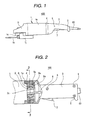
- Fig. 2 is a partial cross-sectional view (side view) of the power tool.
- Fig. 3 is a cross-sectional view of the power tool, taken along the line 3-3 in Fig. 2.
- the disk grinder 100 is roughly composed of a disk grinder main body (power tool main body) 1, a handle 3 and a power cord 60 for supplying the commercial AC power.
- Thepower tool main body 1 comprises amotorportionhousing 1e made of a metallic material, a gear portion housing (gear portion case) 1f made of a metallic material, a tip tool 1h composed of a disk-like grinder attached on a spindle 1s, and a protection cover 1j for protecting a part of the grinder.
- the motor portion housing 1e contains a universal motor, not shown, that is driven by AC power supplied through the power cord 60.
- a field core comprising a field winding of the universal motor or an armature shaft comprising an armature winding and a commutator are attached inside the motor portion housing 1e Within the gear portion housing 1f, there are provided one pair of bevel gears, not shown, to change the direction of the turning force for a rotation shaft of the universal motor and transmit it to the spindle 1s.
- the handle 3 is composed of a case made of a plastic material, for example, in which a power switch 7 electrically connected to the power cord 60 and an electrical part for noise prevention are mounted within the case of this handle 3.
- An elastic body 4 according to the invention is inserted and fitted into a joint between an end portion of the motor portion housing 1e constituting a part of the power tool main body and the opposite end portion of the handle 3.
- the end portion of the motor portion housing 1e and the opposite end portion of the handle 3 carrying the elastic body 4 between them may be, but not limitative to, circular in cross section, in a direction vertical to the central axis. Accordingly, the cross sectional shape of the elastic body 4 carried between both has also a circular shape like a ring.
- the tool main body 1, the elastic body 4 and the handle 3 are integrated to constitute the power tool having the vibration isolating handle as described below.
- Fig. 2 is an enlarged cross-sectional view (side view) of the joint between the power tool main body 1 and the handle 3.
- a spherical handle holder 2 protrudes from an end portion of the power tool main body 1.
- the handle holder 2 has a spherical convex outer circumferential face (outer surface) 2a. That is, the outer circumferential face 2a has the convex outer surface 2a that is spherical radially outward from the central axis of the handle holder 2 in the protruding direction.
- a central portion of the handle holder 2 has a hollow portion 2c parallel to the central axis, and a commercial power feeder line 6 is disposed in this hollow portion 2c.
- an arm portion 8 fitted with the handle holder 2 is provided at the end portion of the handle 3.
- the arm portion 8 has a spherical concave inner circumferential face (inner surface) 8a.
- This inner circumferential face 8a surrounds or covers the handle holder 2 to be fitted or engaged in a small gap with the outer circumferential face 2a of the handle holder 2. That is, the handle holder 2 is fitted to be slidable on the concave inner circumferential face 8a in the arm portion 8 of the handle 3, and inserted into the arm portion 8.
- a depression portion 11 is disposed in at least one position on the outer circumference.
- a projection portion 12 to engage the depression portion 11 provided on the outer circumferential face 2a of the handle holder 2 is disposed on the inner circumferential face 8a of the arm portion 8.
- the handle holder 2 can be engaged without rotation around the central axis.
- the depression portion 11 and the projection portion 12 formed on both the spherical faces of convex and concave portions function as rotation prevention means of the handle holder 2 (or handle 3).
- the elastic body 4 is disposed radially outside the arm portion 8 in cross section in the direction vertical to the central axis. This elastic body 4 is carried between the outer circumferential portion (end portion) 1a of the main body 1 of the power tool and the outer circumferential portion (end portion) 3a of the handle 3a.
- the handle 3 is divided in a direction parallel to the central axis into two handle members 3x and 3y, as shown in Fig. 3.
- the divided two handle members 3x and 3y are integrated by screws 5 (see Fig. 2).
- two handle members 3x and 3y are divided bilaterally in this embodiment, the handle 3 may be integrated of two or more handle members.
- the divided handle members are integrated by screws. In this way, the handle 3 is assembled from a plurality of handle members, whereby the assembling operation of fitting the arm portion 8 of the handle with the handle holder 2 is simplified.
- the handle holder 2 can be engaged without rotation around the central axis by the depression portion 11 disposed on the outer circumferential face 2a of the handle holder 2 and the projection portion 12 disposed on the inner circumferential face 8a of the arm portion 8 to be engaged or fitted with the depression portion 11 in a cross section in the direction vertical to the central axis of the handle holder 2 and the handle 3, or in a cross section as shown in Fig. 3.
- the rotation of the handle 3 is prevented, and the feeder line (electric wire) 6 electrically connected to the switch 7 within the handle 3 is not disconnected, even if it is wired in the hollow portion of the handle holder 2 and the handle 3.
- this is effectively applied to the handle having specific directivity.
- a slide member 15 made of fluororesin and having a small friction coefficient is provided on the surface of the outer circumferential face 2a of the handle holder 2 or the inner circumferential face 8a of the arm portion 8 to reduce the friction between the outer circumferential face 2a and the inner circumferential face 8a.
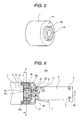
- Fig. 4 is a partial cross-sectional view (side view) of a power tool according to the second embodiment, to which a disk grinder is applied.
- Fig. 5 is a partial perspective view of the power tool main body, broken away along the line 5-5 in Fig. 4.
- the overall appearance view of the second embodiment is the same as that of the first embodiment as shown in Fig. 1.
- the handle holder 2 protruding from the power tool main body 1 has the spherical convex outer circumferential face (outer surface) 2a as in the first embodiment.
- the arm portion 8 of the handle 3 has the spherical concave inner circumferential face (inner surface) 8a as in the first embodiment, in which the spherical convex outer circumferential face 2a is inserted and fitted with the spherical concave inner circumferential face 8a.
- a circular pedestal portion 52 is formed in a portion continuous to the handle holder 2 of the power tool main body 1 and a groove portion 50 is formed in an opposed portion of the circular outer circumference of the pedestal portion 52 in this embodiment, as shown in Fig. 5.
- This groove portion 50 is formed with a projection portion 51 of the arm portion 8 to be fitted with the groove portion 50 of the pedestal portion 52, as shown in Fig. 4.
- the groove portion 50 and the projection portion 51 are provided on the outer circumferential portion different from the convex outer circumferential face 2a and the concave inner circumferential face 8a to receive a moment more radially outward. Thereby, the groove portion 50 and the projection portion 51 are unlikely to break.
- the elastic body 4 can absorb the vibrations in the same way as in the first embodiment.
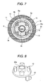
- Fig. 6 is a partial cross-sectional view (side view) of a power tool according to the third embodiment, to which a disk grinder is applied.
- Fig. 7 is a cross-sectional view along the line 7-7 in Fig. 6.
- Fig. 8 is a perspective view of a slide switch 20 for use in the third embodiment.
- the overall appearance view of the third embodiment is the same as that of the first embodiment as shown in Fig. 1.
- the handle holder 2 protruding from the power tool main body 1 has the spherical convex outer circumferential face (outer surface) 2a as in the first embodiment.
- the arm portion 8 of the handle 3 has the spherical concave inner circumferential face (inner surface) 8a as in the first embodiment, in which the spherical convex outer circumferential face 2a is inserted and fitted with the spherical concave inner circumferential face 8a.
- the slide switch 20 contained within the handle 3 is provided with a barrel-like guide 20a engaging the inside of the cylindrical hollow portion 2c of the handle holder 2. That is, the outer surface of the barrel-like guide 20a is engaged, with a slight gap, with the hollow inner surface 2b of the handle holder 2. Also, the slide switch 20 is biased toward the power tool main body 1 by a spring 17 inserted into a plate 16 disposed within the handle 3.
- the projection portion 12 is disposed in the slide switch 20.
- the depression portion 8b is disposed on the spherical concave inner circumferential face 8a of the arm portion 8, corresponding to the depression portion 11 disposed on the spherical convex outer circumferential face 2a for the handle holder 2, whereby a hole portion 21 is partitioned by the depression portion 11 and the depression portion 8b.
- the handle 3 is engaged in the handle holder 2 not to rotate by fitting the projection member 12 into the hole portion 21.
- the depression portion 11 and the projection member 12 function as the rotationpreventionmeans of the handle holder 2 (or handle 3) as in the first embodiment.
- the power tool main body 1 is rotated by 90 degrees around the central axis of the handle holder 2 to stand the tip tool 1h (see Fig. 1) vertically in cutting the concrete or iron material.
- the handle 3 is not rotated, but the switch 7 as shown in Fig. 6 is directed to the foot of the operator to allow the operator to perform the work more easily.
- the slide switch 20 as shown in Fig. 6 is moved against a load of the spring 17 and held in a moved state, so that the projection member 12 fitted into the hole portion 21 gets rid of the hole portion 21 to allow the handle 3 to be rotated. At this time, the operator can rotate the handle 3 by 90 degrees.
- a plurality of depression portions 11 disposed on the outer circumferential face of the handle holder 2 and a plurality of depression portions 8b disposed on the arm portion 8 are disposed to be opposed to each other in a state where the handle 3 is rotated by 90 degrees, and the new hole portion 21 is formed again by rotating the handle 3.
- the operator can engage the handle holder 2 with the arm portion 8 in a state where the handle 3 is rotated by 90 degrees by releasing the slide switch 20, and fitting the projection member 12 into the new hole portion 21 again.
- the elastic body 4 can absorb the vibrations in the same way as in the first embodiment, and the handle 3 can be rotated by 90 degrees and held according to the working substance, whereby the vibration isolating handle having excellent operability can be provided.
- Fig. 9 is a partial cross-sectional view (side view) of a power tool of the disk grinder having the vibration isolating handle according to the fourth embodiment.
- Fig. 10 is a perspective view of the elastic body 4 used in the fourth embodiment.
- the handle holder 2 and the arm portion 8 of the handle 3 have the same shape and structure as in the first and third embodiments.
- a stopper (projection portion) 30 directing toward the power tool main body 1 is placed at a position on the outer diameter side of the arm portion 8 of the handle 3 and on the inner diameter side of the elastic body 4 in a direction vertical to the central axis of the handle holder as shown in Fig. 9.
- a distal end 30a of the stopper 30 does not reach the end portion of the power tool main body 1 so that there is a gap between the power tool main body 1 and it.
- the elastic body 4 is provided with a projection portion 4a at one end contact with the handle 3 or the other end contact with the power tool main body 1, as shown in Fig. 10.
- the projection portion 4a of the elastic body 4 may be formed on either end portion.
- the stopper or projection portion 30 if the stopper or projection portion 30 is not provided, the operator holds the handle 3, and lays a big load on the power tool main body 1, the elastic body 4 is locally compressed to cause the handle 3 to be greatly flexed. As a result, the elastic body 4 is subject to excessive distortion, possibly breaking the elastic body 4.
- the stopper 30 if the stopper 30 is placed on the handle 3, the distal end 30a of the stopper 30 makes contact with the stopper acceptance portion 1m of the tool main body 1, in a process where the handle 3 is flexed, whereby the elastic body 4 has no excessive distortion. Under this action, the flexure of the handle 30 is suppressed, and the breakage of the elastic body 4 is prevented.
- the length of the elastic body 4 in a direction parallel to the central axis of the handle holder 2 is made larger than the length of a gap accommodating the elastic body 4 between the outer circumferential portion 1a of the main body 1 and the outer circumferential portion 3a of handle, and a plurality of projections 4a are disposed on the contact face between the elastic body 4 and the outer circumferential portion 1a of the main body 1 or the outer circumferential portion 3a of the handle 3.
- the concave and convex portions having low rigidity are significantly deformed at first, suppressing a reaction force due to deformation of the elastic body 4, and improving the operability at the time of assembling. Also, even if the elastic body 4 is permanently deformed during the use of the tool for the long time, no gap occurs, because the length of the elastic body 4 is made longer than the length of the gap between the outer circumferential portion 1a of the main body and the outer circumferential portion 3a of the handle. Accordingly, the power tool having the vibration isolating handle has excellent operability.
- Fig. 11 is a partial cross-sectional view (side view) of a power tool of the disk grinder having the vibration isolating handle according to the invention.
- Fig. 12 is a perspective view of the elastic body 4.
- the handle holder 2 and the arm portion 8 of the handle 3 have the same shape and structure as in the first to third embodiments.
- a different point from the above embodiments is that the structure of the elastic body 4 carried between the tool main body 1 and the handle 3 or the armportion 8 is deformed, as shown in Fig. 11 and Fig. 12.
- the projection portions 4a and 4d are disposed on both the contact face 4c of the elastic body 4 with the outer circumferential portion 1a of the tool main body and the contact face 4b of the elastic body 4 with the outer circumferential portion 3a of the handle, and the groove portions 1b and 3b to be fitted around the projections 4a and 4d disposed on the elastic body 4 are disposed on the outer circumferential portion 1a of the main body and the outer circumferential portion 3a of the handle that are opposed.
- the projection portions 1g and 3g are disposed to suppress deformation of the elastic body 4 radially outward.
- the operator presses the handle 3 with the root of the forefinger and grasps the handle 3 with the little finger to raise it.
- the handle 3 is inclined so that the rear end of the handle 3 is lifted up with respect to the central axis line of the power tool main body 1, compressing the elastic body 4 between the outer circumferential portion 3a of the handle and the outer circumferential portion of the power tool main body 1a.
- the elastic body 4 is elongated radially outward of the power tool main body 1 due to elastic deformation, producing a slippage on the contact face between the elastic body 4 and the power tool main body 1 and the elastic body 4 and the handle 3.
- the concave and convex portions to be fitted together are formed the contact face, thereby preventing a slippage on the contact face between the handle 3 and the elastic body 4.
- the effect of suppressing slippage on the contact face with the elastic body 4 is increased by disposing the fitting portions in at least two positions radialy on the contact face. Further, the effect is more remarkable by disposing the fitting portions in at least two or more positions within an angle of 45° circumferentially on the contact face of the elastic body 4.
- the radially outward deformation of the outermost circumferential portion of the elastic body 4 is suppressed by the projection portion 1g disposed in the power tool main body 1 and the projection portion 3g disposed in the handle 3, thereby preventing slippage on the outermost circumferential portion of the contact faces 4c and 4b of the elastic body 4.
- the slippage on the contact face of the elastic body 4 is eliminated, whereby the vibration isolating handle with excellent operability and less secular change can be provided.
- the initial deflection amount of the handle 3 when the operator grasps the handle 3 is caused only by deformation of the elastic body 4, and suppressed more effectively than with slippage, whereby the operator is increased in the reliability of operating the handle 3.
- the shape of the joint between the power tool and the handle is circular in cross section in the above embodiments
- the invention is also applicable to the rectangular shape.
- the sectional shape of the elastic body is rectangular shape of ring.
- the elastic body is assembled as a simplex having the shape of ring in the above embodiment, a plurality of ring shapes for the elastic body may be integrated and assembled.
- the power tool is the disk grinder in the above embodiments, the invention may be applicable to other power tools.
- the handle holder having the spherical convex outer circumferential face and the handle with the arm portion having the spherical concave inner circumferential face are fitted together, and the elastic body is carried between the handle holder and the handle on the outer circumferential portion of the fitted portion, whereby the vibration isolating handle having excellent operability and less secular change can be provided.
- the handle holder has a spherical convex outer circumferential face
- the arm portion surrounding the handle holder has a spherical concave inner circumferential face
- the convex outer circumferential face of the handle holder being inserted and fitted into the concave inner circumferential face of the arm portion
- the elastic body is carried between the power tool main body and the handle around the outer circumference of the handle holder in a radial direction vertical to the central axis of the handle holder in the protruding direction, whereby the concave inner circumferential face and the convex outer circumferential face acting as anti-slip of the handle are placed in an overlap state with the elastic body in the direction of the central axis.
- the elastic body for vibration absorption is carried between the power tool main body and the handle, it is unnecessary to provide the rib to demarcate the space that contains the elastic body. Hence, it is possible to provide the power tool that can absorb the vibrations efficiently and has a small size.
- the elastic body is carried between the power tool and the handle, the first contact face between one end of the elastic body and the power tool main body and the second contact face between the other end of the elastic body and the handle are provided with the concave and convex fitting portions that can be fitted together, or the length of the elastic body in the direction parallel to the central axis of the handle holder is greater than the size of the gap for the elastic body carried and contained between the power tool main body and the handle to form the convex and concave portions contacting the handle or the power tool main body, making it possible to eliminate the slippage on the contact face, whereby the operability or workability can be improved. Also, it is possible to provide the vibration isolating handle with less secular change.
- the handle can be held in a state where it is rotated by 90 degrees, whereby it is possible to provide the power tool having the vibration isolating handle that is excellent in the workability, can absorb the vibrations efficiently and has a small size.
- the assembly may be performed in accordance with the following procedure. That is, the elastic body is incorporated around the outer circumference of the handle holder, and then each of the divided handle members is incorporated from behind the elastic body so that the concave inner circumferential face and the convex inner circumferential face may be engaged. At this time, if the axial length of the elastic body is set longer than the gap where the elastic body is contained, the elastic body presses the handle axially to prevent the handle member from entering deeply.
- the convex outer circumferential face and the concave inner circumferential face are formed as spherical, whereby if the divided handle members are joined by screws in this state, the handle members enter deeply against the elastic body due to inclination of the convex outer circumferential face and the concave inner circumferential face. Thereby, the assembling operation of the power tool is simplified.
Landscapes
- Engineering & Computer Science (AREA)
- Mechanical Engineering (AREA)
- Percussive Tools And Related Accessories (AREA)
- Portable Power Tools In General (AREA)
- Finish Polishing, Edge Sharpening, And Grinding By Specific Grinding Devices (AREA)
- Portable Nailing Machines And Staplers (AREA)
Applications Claiming Priority (2)
| Application Number | Priority Date | Filing Date | Title |
|---|---|---|---|
| JP2004315029A JP4857542B2 (ja) | 2004-10-29 | 2004-10-29 | 動力工具 |
| EP05023654A EP1652633B1 (de) | 2004-10-29 | 2005-10-28 | Kraftangetriebenes Werkzeug mit Griffvorrichtung mit elastischem Element |
Related Parent Applications (1)
| Application Number | Title | Priority Date | Filing Date |
|---|---|---|---|
| EP05023654A Division EP1652633B1 (de) | 2004-10-29 | 2005-10-28 | Kraftangetriebenes Werkzeug mit Griffvorrichtung mit elastischem Element |
Publications (3)
| Publication Number | Publication Date |
|---|---|
| EP1889692A2 true EP1889692A2 (de) | 2008-02-20 |
| EP1889692A3 EP1889692A3 (de) | 2008-11-19 |
| EP1889692B1 EP1889692B1 (de) | 2017-06-21 |
Family
ID=35519775
Family Applications (2)
| Application Number | Title | Priority Date | Filing Date |
|---|---|---|---|
| EP07022683.2A Expired - Lifetime EP1889692B1 (de) | 2004-10-29 | 2005-10-28 | Kraftangetriebenes Werkzeug mit Griffvorrichtung mit elastischem Element |
| EP05023654A Expired - Lifetime EP1652633B1 (de) | 2004-10-29 | 2005-10-28 | Kraftangetriebenes Werkzeug mit Griffvorrichtung mit elastischem Element |
Family Applications After (1)
| Application Number | Title | Priority Date | Filing Date |
|---|---|---|---|
| EP05023654A Expired - Lifetime EP1652633B1 (de) | 2004-10-29 | 2005-10-28 | Kraftangetriebenes Werkzeug mit Griffvorrichtung mit elastischem Element |
Country Status (7)
| Country | Link |
|---|---|
| US (1) | US7721818B2 (de) |
| EP (2) | EP1889692B1 (de) |
| JP (1) | JP4857542B2 (de) |
| CN (2) | CN100436077C (de) |
| AT (1) | ATE394201T1 (de) |
| DE (1) | DE602005006497D1 (de) |
| ES (1) | ES2307103T3 (de) |
Cited By (1)
| Publication number | Priority date | Publication date | Assignee | Title |
|---|---|---|---|---|
| GB2444130B (en) * | 2006-06-16 | 2010-05-19 | Bosch Gmbh Robert | Hand tool machine |
Families Citing this family (45)
| Publication number | Priority date | Publication date | Assignee | Title |
|---|---|---|---|---|
| DE10005080C1 (de) * | 2000-02-04 | 2001-08-02 | Bosch Gmbh Robert | Handwerkzeugmaschine mit zumindest einem Handgriff und wenigstens einem elastischen, schwingungsdämpfenden Element |
| JP4575223B2 (ja) * | 2005-04-20 | 2010-11-04 | 株式会社マキタ | 回転工具 |
| US8496073B2 (en) * | 2005-10-29 | 2013-07-30 | Aeg Electric Tools Gmbh | Portable power tool |
| DE102005062883A1 (de) * | 2005-12-29 | 2007-07-05 | Robert Bosch Gmbh | Schwingungsreduktion bei Elektrowerkzeugen |
| JP4962896B2 (ja) | 2006-03-10 | 2012-06-27 | 日立工機株式会社 | 動力工具 |
| EP1867443B1 (de) * | 2006-06-14 | 2009-07-15 | AEG Electric Tools GmbH | Zusatzhandgriff einer handgeführten Werkzeugmaschine |
| US8006778B2 (en) * | 2006-06-16 | 2011-08-30 | Robert Bosch Gmbh | Handheld power tool |
| DE102007012312A1 (de) * | 2007-03-14 | 2008-09-18 | Robert Bosch Gmbh | Handgriff |
| WO2008110546A1 (de) * | 2007-03-15 | 2008-09-18 | Robert Bosch Gmbh | Handgriff mit einem dämpfungselement mit einer gelenkeinheit |
| JP2008264935A (ja) * | 2007-04-20 | 2008-11-06 | Makita Corp | 手持ち工具のハンドル |
| US20090000132A1 (en) * | 2007-06-29 | 2009-01-01 | The Stanley Works | Reduced vibration saw handle |
| DE102007030703A1 (de) * | 2007-07-02 | 2009-01-08 | Robert Bosch Gmbh | Elastische Verbindung zwischen Gehäuseteilen motorisch angetriebener Werkzeugmaschinen |
| DE102008063113A1 (de) * | 2008-01-09 | 2009-07-16 | Marquardt Gmbh | Elektrowerkzeug |
| JP5403477B2 (ja) * | 2008-03-19 | 2014-01-29 | 日立工機株式会社 | 電動工具 |
| DE102008001268A1 (de) * | 2008-04-18 | 2009-10-22 | Robert Bosch Gmbh | Steckeranordnung in einer Werkzeugmaschine, insbesondere in einer Handwerkzeugmaschine |
| DE102008001252A1 (de) * | 2008-04-18 | 2009-10-22 | Robert Bosch Gmbh | Werkzeugmaschine, insbesondere Handwerkzeugmaschine |
| DE102008001829A1 (de) * | 2008-05-16 | 2009-11-19 | Robert Bosch Gmbh | Handwerkzeugmaschine, insbesondere Akku-Schrauber bzw. Akku-Bohrer |
| US7911090B2 (en) * | 2008-08-20 | 2011-03-22 | Robert Bosch Gmbh | Stator of an electrical machine, electrical machine, and power tool |
| DE102009002975A1 (de) * | 2009-05-11 | 2010-11-18 | Robert Bosch Gmbh | Handwerkzeugmaschine, insbesondere Elektrohandwerkzeugmaschine |
| DE102009002967A1 (de) * | 2009-05-11 | 2010-11-18 | Robert Bosch Gmbh | Handwerkzeugmaschine, insbesondere Elektrohandwerkzeugmaschine |
| JP5395531B2 (ja) * | 2009-06-19 | 2014-01-22 | 株式会社マキタ | 作業工具 |
| JP4934717B2 (ja) * | 2009-12-22 | 2012-05-16 | 株式会社マキタ | 回転工具 |
| DE102010030494A1 (de) * | 2010-06-24 | 2011-12-29 | Robert Bosch Gmbh | Ankerwellenlagereinheit |
| GB201112833D0 (en) * | 2011-07-26 | 2011-09-07 | Black & Decker Inc | A hammer drill |
| WO2013116680A1 (en) | 2012-02-03 | 2013-08-08 | Milwaukee Electric Tool Corporation | Rotary hammer |
| US9849577B2 (en) | 2012-02-03 | 2017-12-26 | Milwaukee Electric Tool Corporation | Rotary hammer |
| DE102012103604A1 (de) * | 2012-04-24 | 2013-10-24 | C. & E. Fein Gmbh | Handführbare Werkzeugmaschine mit Gehäuse |
| DE102012103587A1 (de) * | 2012-04-24 | 2013-10-24 | C. & E. Fein Gmbh | Handführbare Werkzeugmaschine mit Außengehäuse |
| US8966773B2 (en) | 2012-07-06 | 2015-03-03 | Techtronic Power Tools Technology Limited | Power tool including an anti-vibration handle |
| CN105517743B (zh) * | 2013-03-14 | 2018-11-27 | 罗伯特·博世有限公司 | 具有振动隔离的手持电动工具 |
| DE102014201436A1 (de) * | 2014-01-27 | 2015-07-30 | Robert Bosch Gmbh | Handwerkzeugmaschine |
| CN105312985B (zh) * | 2015-03-16 | 2018-06-12 | 宋波 | 用于角磨机的自助式夹持架 |
| CN107097184B (zh) * | 2016-02-19 | 2021-08-31 | 株式会社牧田 | 作业工具 |
| JP6703417B2 (ja) * | 2016-02-19 | 2020-06-03 | 株式会社マキタ | 作業工具 |
| JP6399066B2 (ja) * | 2016-09-27 | 2018-10-03 | オムロン株式会社 | トリガースイッチ |
| CN108857776A (zh) * | 2018-07-04 | 2018-11-23 | 宁波良业电器有限公司 | 一种可调节角度的角磨机 |
| ES2941990T3 (es) * | 2018-07-25 | 2023-05-29 | Robel Bahnbaumaschinen Gmbh | Bateadora vibratoria para compactar un lecho de balasto de una vía |
| US10625906B1 (en) * | 2018-11-16 | 2020-04-21 | Stasher, Inc. | Inside out method of manufacturing a container with a leak resistant seal |
| US12021437B2 (en) | 2019-06-12 | 2024-06-25 | Milwaukee Electric Tool Corporation | Rotary power tool |
| US11931879B2 (en) | 2021-06-07 | 2024-03-19 | Black & Decker Inc. | Power tool dual-trigger operation |
| US11759938B2 (en) | 2021-10-19 | 2023-09-19 | Makita Corporation | Impact tool |
| EP4230355A1 (de) * | 2022-02-21 | 2023-08-23 | Andreas Stihl AG & Co. KG | Tragbares arbeitsgerät |
| EP4302926B1 (de) | 2022-06-16 | 2025-08-06 | Milwaukee Electric Tool Corporation | Kompaktes schlagwerkzeug |
| US12485526B2 (en) | 2023-03-13 | 2025-12-02 | Black & Decker Inc. | Gear case grip accessory for power tool |
| CN220863921U (zh) * | 2023-09-21 | 2024-04-30 | 江苏大艺科技股份有限公司 | 电动工具 |
Citations (1)
| Publication number | Priority date | Publication date | Assignee | Title |
|---|---|---|---|---|
| JP2534318B2 (ja) | 1988-04-30 | 1996-09-11 | 日立工機株式会社 | 動力工具の防振ハンドル |
Family Cites Families (21)
| Publication number | Priority date | Publication date | Assignee | Title |
|---|---|---|---|---|
| US2101869A (en) * | 1934-11-27 | 1937-12-14 | Sullivan Machinery Co | Vibration reducing means |
| US3911580A (en) * | 1974-07-03 | 1975-10-14 | Mcculloch Corp | Coaxial vibrating isolation unit for a chain saw including discrete, independently operable elements |
| DE3312195A1 (de) * | 1983-04-02 | 1984-10-11 | Wacker-Werke Gmbh & Co Kg, 8077 Reichertshofen | Handgefuehrter schlag- und bohrhammer |
| US5072917A (en) * | 1987-05-21 | 1991-12-17 | Pleva Walter F | Uniform loading springs of improved configuration |
| JP2931025B2 (ja) * | 1989-03-18 | 1999-08-09 | アンドレアス シュティール | 抗振動エレメントによって結合された握り部を有するモータ駆動手操作作業機 |
| DE4011124A1 (de) * | 1990-04-06 | 1991-10-10 | Metabowerke Kg | Vibrationsgedaempfter handgriff |
| AU651269B2 (en) * | 1991-12-17 | 1994-07-14 | Ingersoll-Rand Company | Apparatus for reducing vibration transmission in hand-held tool |
| JP3276386B2 (ja) * | 1991-12-20 | 2002-04-22 | 兼松日産農林株式会社 | 手持ち式打撃工具の防振ハンドル |
| JPH08126975A (ja) * | 1994-10-28 | 1996-05-21 | Hitachi Koki Co Ltd | 電気ハンマの防振ハンドル |
| DE19530712B4 (de) * | 1995-08-21 | 2006-12-28 | Fa. Andreas Stihl | Antivibrationselement zur Anordnung zwischen einer Motoreinheit und einer Griffeinheit bei einem handgeführten Arbeitsgerät |
| US6026910A (en) * | 1998-01-13 | 2000-02-22 | Chicago Pneumatic Tool Company | Power tool and vibration isolator therefor |
| FR2797208B1 (fr) * | 1999-08-03 | 2002-10-18 | Stihl Maschf Andreas | Element antivibrations pourvu d'une surete d'arrachement |
| GB2391501B (en) * | 2000-03-10 | 2004-06-02 | Bayly Design Ass Pty Ltd | Power tool |
| JP2002254336A (ja) * | 2001-03-02 | 2002-09-10 | Hitachi Koki Co Ltd | 電動工具 |
| CN1422730A (zh) * | 2001-12-06 | 2003-06-11 | 陈秀如 | 气动工具的减震装置 |
| CN2537524Y (zh) * | 2002-04-30 | 2003-02-26 | 苏州宝时得电动工具有限公司 | 带有至少一个手柄的电动工具机 |
| DE10248866B4 (de) * | 2002-10-18 | 2016-03-17 | Robert Bosch Gmbh | Handwerkzeugmaschine |
| JP4228720B2 (ja) * | 2003-02-21 | 2009-02-25 | 日立工機株式会社 | 防振ハンドル |
| EP1514648B1 (de) * | 2003-09-10 | 2013-11-20 | Makita Corporation | Schwingungsfreier Griff |
| US7252156B2 (en) * | 2005-03-31 | 2007-08-07 | Makita Corporation | Vibration isolation handle |
| JP4575223B2 (ja) * | 2005-04-20 | 2010-11-04 | 株式会社マキタ | 回転工具 |
-
2004
- 2004-10-29 JP JP2004315029A patent/JP4857542B2/ja not_active Expired - Lifetime
-
2005
- 2005-10-28 DE DE602005006497T patent/DE602005006497D1/de not_active Expired - Lifetime
- 2005-10-28 CN CNB2005101167718A patent/CN100436077C/zh not_active Expired - Lifetime
- 2005-10-28 AT AT05023654T patent/ATE394201T1/de not_active IP Right Cessation
- 2005-10-28 CN CNA200810149366XA patent/CN101367188A/zh active Pending
- 2005-10-28 EP EP07022683.2A patent/EP1889692B1/de not_active Expired - Lifetime
- 2005-10-28 ES ES05023654T patent/ES2307103T3/es not_active Expired - Lifetime
- 2005-10-28 EP EP05023654A patent/EP1652633B1/de not_active Expired - Lifetime
- 2005-10-28 US US11/260,418 patent/US7721818B2/en not_active Expired - Lifetime
Patent Citations (1)
| Publication number | Priority date | Publication date | Assignee | Title |
|---|---|---|---|---|
| JP2534318B2 (ja) | 1988-04-30 | 1996-09-11 | 日立工機株式会社 | 動力工具の防振ハンドル |
Cited By (1)
| Publication number | Priority date | Publication date | Assignee | Title |
|---|---|---|---|---|
| GB2444130B (en) * | 2006-06-16 | 2010-05-19 | Bosch Gmbh Robert | Hand tool machine |
Also Published As
| Publication number | Publication date |
|---|---|
| EP1652633B1 (de) | 2008-05-07 |
| US20060113098A1 (en) | 2006-06-01 |
| EP1889692B1 (de) | 2017-06-21 |
| EP1889692A3 (de) | 2008-11-19 |
| CN1765591A (zh) | 2006-05-03 |
| JP4857542B2 (ja) | 2012-01-18 |
| ATE394201T1 (de) | 2008-05-15 |
| ES2307103T3 (es) | 2008-11-16 |
| JP2006123091A (ja) | 2006-05-18 |
| CN101367188A (zh) | 2009-02-18 |
| EP1652633A1 (de) | 2006-05-03 |
| DE602005006497D1 (de) | 2008-06-19 |
| US7721818B2 (en) | 2010-05-25 |
| CN100436077C (zh) | 2008-11-26 |
Similar Documents
| Publication | Publication Date | Title |
|---|---|---|
| EP1889692B1 (de) | Kraftangetriebenes Werkzeug mit Griffvorrichtung mit elastischem Element | |
| JP2534318B2 (ja) | 動力工具の防振ハンドル | |
| CN100351539C (zh) | 电动工具和装配于其中的齿轮单元 | |
| EP2295208B1 (de) | Rotierendes Kraftwerkzeug | |
| JP4996696B2 (ja) | 電気機械を振動遮断しながら保持するための装置 | |
| CN100475454C (zh) | 冲击工具 | |
| US7517276B2 (en) | Power tool | |
| US7967079B2 (en) | Hand-held power tool | |
| JP2012171023A (ja) | 防振ハンドル | |
| EP2492051A1 (de) | Stossdämpfermechanismus für einen getriebezug | |
| JP6044718B2 (ja) | グラインダ | |
| EP2599592B1 (de) | Elektrowerkzeuge | |
| JP2013063494A (ja) | 電動工具 | |
| JP5187059B2 (ja) | 電動工具 | |
| JPS6216297Y2 (de) | ||
| KR20240123958A (ko) | 휴대용 전동공구의 배터리부 진동저감구조 | |
| JP3729230B2 (ja) | 防振装置 | |
| KR101609614B1 (ko) | 모터용 브러시 홀더 어셈블리 | |
| CN221755957U (zh) | 用于电动手持工具机的冲击机构 | |
| CN216883814U (zh) | 具有防振组件的动力工具 | |
| JPH08118248A (ja) | 電動工具のモータ防振装置 | |
| JP2006123146A (ja) | 動力工具 | |
| JP4457449B2 (ja) | モータのロータ | |
| CN120645156A (zh) | 具有角向传动装置的手持式工具机 | |
| JP2021014008A (ja) | 電動工具 |
Legal Events
| Date | Code | Title | Description |
|---|---|---|---|
| PUAI | Public reference made under article 153(3) epc to a published international application that has entered the european phase |
Free format text: ORIGINAL CODE: 0009012 |
|
| 17P | Request for examination filed |
Effective date: 20071122 |
|
| AC | Divisional application: reference to earlier application |
Ref document number: 1652633 Country of ref document: EP Kind code of ref document: P |
|
| AK | Designated contracting states |
Kind code of ref document: A2 Designated state(s): AT BE BG CH CY CZ DE DK EE ES FI FR GB GR HU IE IS IT LI LT LU LV MC NL PL PT RO SE SI SK TR |
|
| PUAL | Search report despatched |
Free format text: ORIGINAL CODE: 0009013 |
|
| AK | Designated contracting states |
Kind code of ref document: A3 Designated state(s): AT BE BG CH CY CZ DE DK EE ES FI FR GB GR HU IE IS IT LI LT LU LV MC NL PL PT RO SE SI SK TR |
|
| AKX | Designation fees paid |
Designated state(s): AT BE BG CH CY CZ DE DK EE ES FI FR GB GR HU IE IS IT LI LT LU LV MC NL PL PT RO SE SI SK TR |
|
| 17Q | First examination report despatched |
Effective date: 20090706 |
|
| RIC1 | Information provided on ipc code assigned before grant |
Ipc: B24B 23/02 20060101AFI20161117BHEP |
|
| RIC1 | Information provided on ipc code assigned before grant |
Ipc: B25F 5/00 20060101AFI20161122BHEP |
|
| GRAP | Despatch of communication of intention to grant a patent |
Free format text: ORIGINAL CODE: EPIDOSNIGR1 |
|
| INTG | Intention to grant announced |
Effective date: 20170105 |
|
| GRAS | Grant fee paid |
Free format text: ORIGINAL CODE: EPIDOSNIGR3 |
|
| GRAA | (expected) grant |
Free format text: ORIGINAL CODE: 0009210 |
|
| AC | Divisional application: reference to earlier application |
Ref document number: 1652633 Country of ref document: EP Kind code of ref document: P |
|
| AK | Designated contracting states |
Kind code of ref document: B1 Designated state(s): AT BE BG CH CY CZ DE DK EE ES FI FR GB GR HU IE IS IT LI LT LU LV MC NL PL PT RO SE SI SK TR |
|
| REG | Reference to a national code |
Ref country code: GB Ref legal event code: FG4D |
|
| REG | Reference to a national code |
Ref country code: CH Ref legal event code: EP |
|
| REG | Reference to a national code |
Ref country code: IE Ref legal event code: FG4D |
|
| REG | Reference to a national code |
Ref country code: AT Ref legal event code: REF Ref document number: 902501 Country of ref document: AT Kind code of ref document: T Effective date: 20170715 |
|
| REG | Reference to a national code |
Ref country code: RO Ref legal event code: EPE |
|
| REG | Reference to a national code |
Ref country code: DE Ref legal event code: R096 Ref document number: 602005052191 Country of ref document: DE |
|
| REG | Reference to a national code |
Ref country code: FR Ref legal event code: PLFP Year of fee payment: 13 |
|
| REG | Reference to a national code |
Ref country code: NL Ref legal event code: MP Effective date: 20170621 |
|
| PG25 | Lapsed in a contracting state [announced via postgrant information from national office to epo] |
Ref country code: FI Free format text: LAPSE BECAUSE OF FAILURE TO SUBMIT A TRANSLATION OF THE DESCRIPTION OR TO PAY THE FEE WITHIN THE PRESCRIBED TIME-LIMIT Effective date: 20170621 Ref country code: LT Free format text: LAPSE BECAUSE OF FAILURE TO SUBMIT A TRANSLATION OF THE DESCRIPTION OR TO PAY THE FEE WITHIN THE PRESCRIBED TIME-LIMIT Effective date: 20170621 Ref country code: GR Free format text: LAPSE BECAUSE OF FAILURE TO SUBMIT A TRANSLATION OF THE DESCRIPTION OR TO PAY THE FEE WITHIN THE PRESCRIBED TIME-LIMIT Effective date: 20170922 |
|
| REG | Reference to a national code |
Ref country code: LT Ref legal event code: MG4D |
|
| REG | Reference to a national code |
Ref country code: AT Ref legal event code: MK05 Ref document number: 902501 Country of ref document: AT Kind code of ref document: T Effective date: 20170621 |
|
| PG25 | Lapsed in a contracting state [announced via postgrant information from national office to epo] |
Ref country code: LV Free format text: LAPSE BECAUSE OF FAILURE TO SUBMIT A TRANSLATION OF THE DESCRIPTION OR TO PAY THE FEE WITHIN THE PRESCRIBED TIME-LIMIT Effective date: 20170621 Ref country code: NL Free format text: LAPSE BECAUSE OF FAILURE TO SUBMIT A TRANSLATION OF THE DESCRIPTION OR TO PAY THE FEE WITHIN THE PRESCRIBED TIME-LIMIT Effective date: 20170621 Ref country code: BG Free format text: LAPSE BECAUSE OF FAILURE TO SUBMIT A TRANSLATION OF THE DESCRIPTION OR TO PAY THE FEE WITHIN THE PRESCRIBED TIME-LIMIT Effective date: 20170921 Ref country code: SE Free format text: LAPSE BECAUSE OF FAILURE TO SUBMIT A TRANSLATION OF THE DESCRIPTION OR TO PAY THE FEE WITHIN THE PRESCRIBED TIME-LIMIT Effective date: 20170621 |
|
| PG25 | Lapsed in a contracting state [announced via postgrant information from national office to epo] |
Ref country code: EE Free format text: LAPSE BECAUSE OF FAILURE TO SUBMIT A TRANSLATION OF THE DESCRIPTION OR TO PAY THE FEE WITHIN THE PRESCRIBED TIME-LIMIT Effective date: 20170621 Ref country code: SK Free format text: LAPSE BECAUSE OF FAILURE TO SUBMIT A TRANSLATION OF THE DESCRIPTION OR TO PAY THE FEE WITHIN THE PRESCRIBED TIME-LIMIT Effective date: 20170621 Ref country code: CZ Free format text: LAPSE BECAUSE OF FAILURE TO SUBMIT A TRANSLATION OF THE DESCRIPTION OR TO PAY THE FEE WITHIN THE PRESCRIBED TIME-LIMIT Effective date: 20170621 Ref country code: AT Free format text: LAPSE BECAUSE OF FAILURE TO SUBMIT A TRANSLATION OF THE DESCRIPTION OR TO PAY THE FEE WITHIN THE PRESCRIBED TIME-LIMIT Effective date: 20170621 |
|
| PG25 | Lapsed in a contracting state [announced via postgrant information from national office to epo] |
Ref country code: IT Free format text: LAPSE BECAUSE OF FAILURE TO SUBMIT A TRANSLATION OF THE DESCRIPTION OR TO PAY THE FEE WITHIN THE PRESCRIBED TIME-LIMIT Effective date: 20170621 Ref country code: IS Free format text: LAPSE BECAUSE OF FAILURE TO SUBMIT A TRANSLATION OF THE DESCRIPTION OR TO PAY THE FEE WITHIN THE PRESCRIBED TIME-LIMIT Effective date: 20171021 Ref country code: ES Free format text: LAPSE BECAUSE OF FAILURE TO SUBMIT A TRANSLATION OF THE DESCRIPTION OR TO PAY THE FEE WITHIN THE PRESCRIBED TIME-LIMIT Effective date: 20170621 Ref country code: PL Free format text: LAPSE BECAUSE OF FAILURE TO SUBMIT A TRANSLATION OF THE DESCRIPTION OR TO PAY THE FEE WITHIN THE PRESCRIBED TIME-LIMIT Effective date: 20170621 |
|
| REG | Reference to a national code |
Ref country code: DE Ref legal event code: R097 Ref document number: 602005052191 Country of ref document: DE |
|
| PLBE | No opposition filed within time limit |
Free format text: ORIGINAL CODE: 0009261 |
|
| STAA | Information on the status of an ep patent application or granted ep patent |
Free format text: STATUS: NO OPPOSITION FILED WITHIN TIME LIMIT |
|
| PG25 | Lapsed in a contracting state [announced via postgrant information from national office to epo] |
Ref country code: DK Free format text: LAPSE BECAUSE OF FAILURE TO SUBMIT A TRANSLATION OF THE DESCRIPTION OR TO PAY THE FEE WITHIN THE PRESCRIBED TIME-LIMIT Effective date: 20170621 |
|
| 26N | No opposition filed |
Effective date: 20180322 |
|
| PG25 | Lapsed in a contracting state [announced via postgrant information from national office to epo] |
Ref country code: MC Free format text: LAPSE BECAUSE OF FAILURE TO SUBMIT A TRANSLATION OF THE DESCRIPTION OR TO PAY THE FEE WITHIN THE PRESCRIBED TIME-LIMIT Effective date: 20170621 |
|
| REG | Reference to a national code |
Ref country code: CH Ref legal event code: PL |
|
| REG | Reference to a national code |
Ref country code: DE Ref legal event code: R081 Ref document number: 602005052191 Country of ref document: DE Owner name: KOKI HOLDINGS CO., LTD., JP Free format text: FORMER OWNER: HITACHI KOKI CO., LTD., TOKYO, JP |
|
| REG | Reference to a national code |
Ref country code: IE Ref legal event code: MM4A |
|
| PG25 | Lapsed in a contracting state [announced via postgrant information from national office to epo] |
Ref country code: CH Free format text: LAPSE BECAUSE OF NON-PAYMENT OF DUE FEES Effective date: 20171031 Ref country code: LU Free format text: LAPSE BECAUSE OF NON-PAYMENT OF DUE FEES Effective date: 20171028 Ref country code: LI Free format text: LAPSE BECAUSE OF NON-PAYMENT OF DUE FEES Effective date: 20171031 |
|
| REG | Reference to a national code |
Ref country code: BE Ref legal event code: MM Effective date: 20171031 |
|
| PG25 | Lapsed in a contracting state [announced via postgrant information from national office to epo] |
Ref country code: BE Free format text: LAPSE BECAUSE OF NON-PAYMENT OF DUE FEES Effective date: 20171031 Ref country code: SI Free format text: LAPSE BECAUSE OF FAILURE TO SUBMIT A TRANSLATION OF THE DESCRIPTION OR TO PAY THE FEE WITHIN THE PRESCRIBED TIME-LIMIT Effective date: 20170621 |
|
| REG | Reference to a national code |
Ref country code: FR Ref legal event code: PLFP Year of fee payment: 14 |
|
| PG25 | Lapsed in a contracting state [announced via postgrant information from national office to epo] |
Ref country code: IE Free format text: LAPSE BECAUSE OF NON-PAYMENT OF DUE FEES Effective date: 20171028 |
|
| PG25 | Lapsed in a contracting state [announced via postgrant information from national office to epo] |
Ref country code: HU Free format text: LAPSE BECAUSE OF FAILURE TO SUBMIT A TRANSLATION OF THE DESCRIPTION OR TO PAY THE FEE WITHIN THE PRESCRIBED TIME-LIMIT; INVALID AB INITIO Effective date: 20051028 |
|
| PG25 | Lapsed in a contracting state [announced via postgrant information from national office to epo] |
Ref country code: CY Free format text: LAPSE BECAUSE OF NON-PAYMENT OF DUE FEES Effective date: 20170621 |
|
| PG25 | Lapsed in a contracting state [announced via postgrant information from national office to epo] |
Ref country code: TR Free format text: LAPSE BECAUSE OF FAILURE TO SUBMIT A TRANSLATION OF THE DESCRIPTION OR TO PAY THE FEE WITHIN THE PRESCRIBED TIME-LIMIT Effective date: 20170621 |
|
| PG25 | Lapsed in a contracting state [announced via postgrant information from national office to epo] |
Ref country code: PT Free format text: LAPSE BECAUSE OF FAILURE TO SUBMIT A TRANSLATION OF THE DESCRIPTION OR TO PAY THE FEE WITHIN THE PRESCRIBED TIME-LIMIT Effective date: 20170621 |
|
| REG | Reference to a national code |
Ref country code: DE Ref legal event code: R084 Ref document number: 602005052191 Country of ref document: DE |
|
| REG | Reference to a national code |
Ref country code: GB Ref legal event code: 746 Effective date: 20220901 |
|
| PGFP | Annual fee paid to national office [announced via postgrant information from national office to epo] |
Ref country code: DE Payment date: 20241021 Year of fee payment: 20 |
|
| PGFP | Annual fee paid to national office [announced via postgrant information from national office to epo] |
Ref country code: GB Payment date: 20241025 Year of fee payment: 20 |
|
| PGFP | Annual fee paid to national office [announced via postgrant information from national office to epo] |
Ref country code: FR Payment date: 20241021 Year of fee payment: 20 |
|
| PGFP | Annual fee paid to national office [announced via postgrant information from national office to epo] |
Ref country code: RO Payment date: 20241021 Year of fee payment: 20 |
|
| REG | Reference to a national code |
Ref country code: DE Ref legal event code: R071 Ref document number: 602005052191 Country of ref document: DE |
|
| REG | Reference to a national code |
Ref country code: GB Ref legal event code: PE20 Expiry date: 20251027 |