EP1844238B1 - Compressor discharge muffler - Google Patents
Compressor discharge muffler Download PDFInfo
- Publication number
- EP1844238B1 EP1844238B1 EP06719700.4A EP06719700A EP1844238B1 EP 1844238 B1 EP1844238 B1 EP 1844238B1 EP 06719700 A EP06719700 A EP 06719700A EP 1844238 B1 EP1844238 B1 EP 1844238B1
- Authority
- EP
- European Patent Office
- Prior art keywords
- tubes
- gasket
- plate
- compressor
- muffler
- Prior art date
- Legal status (The legal status is an assumption and is not a legal conclusion. Google has not performed a legal analysis and makes no representation as to the accuracy of the status listed.)
- Expired - Fee Related
Links
- 239000003507 refrigerant Substances 0.000 claims description 29
- 239000012530 fluid Substances 0.000 claims description 12
- 238000010276 construction Methods 0.000 claims description 9
- 238000004891 communication Methods 0.000 claims description 3
- 238000007599 discharging Methods 0.000 claims description 3
- 239000003190 viscoelastic substance Substances 0.000 claims description 2
- 239000007788 liquid Substances 0.000 description 11
- 238000005057 refrigeration Methods 0.000 description 7
- 230000008901 benefit Effects 0.000 description 4
- 239000000463 material Substances 0.000 description 4
- 230000008859 change Effects 0.000 description 3
- 238000010438 heat treatment Methods 0.000 description 3
- 230000010349 pulsation Effects 0.000 description 3
- XLYOFNOQVPJJNP-UHFFFAOYSA-N water Substances O XLYOFNOQVPJJNP-UHFFFAOYSA-N 0.000 description 3
- FAPWRFPIFSIZLT-UHFFFAOYSA-M Sodium chloride Chemical compound [Na+].[Cl-] FAPWRFPIFSIZLT-UHFFFAOYSA-M 0.000 description 2
- 238000004378 air conditioning Methods 0.000 description 2
- 230000002238 attenuated effect Effects 0.000 description 2
- 239000012267 brine Substances 0.000 description 2
- 230000006835 compression Effects 0.000 description 2
- 238000007906 compression Methods 0.000 description 2
- 238000001816 cooling Methods 0.000 description 2
- -1 e.g. Substances 0.000 description 2
- 229910052751 metal Inorganic materials 0.000 description 2
- 239000002184 metal Substances 0.000 description 2
- 230000009467 reduction Effects 0.000 description 2
- HPALAKNZSZLMCH-UHFFFAOYSA-M sodium;chloride;hydrate Chemical compound O.[Na+].[Cl-] HPALAKNZSZLMCH-UHFFFAOYSA-M 0.000 description 2
- 238000009423 ventilation Methods 0.000 description 2
- 238000003466 welding Methods 0.000 description 2
- UXVMQQNJUSDDNG-UHFFFAOYSA-L Calcium chloride Chemical compound [Cl-].[Cl-].[Ca+2] UXVMQQNJUSDDNG-UHFFFAOYSA-L 0.000 description 1
- VGGSQFUCUMXWEO-UHFFFAOYSA-N Ethene Chemical compound C=C VGGSQFUCUMXWEO-UHFFFAOYSA-N 0.000 description 1
- 239000005977 Ethylene Substances 0.000 description 1
- 230000009471 action Effects 0.000 description 1
- 239000000853 adhesive Substances 0.000 description 1
- 230000001070 adhesive effect Effects 0.000 description 1
- 230000002411 adverse Effects 0.000 description 1
- 239000001110 calcium chloride Substances 0.000 description 1
- 229910001628 calcium chloride Inorganic materials 0.000 description 1
- 238000005266 casting Methods 0.000 description 1
- 230000007423 decrease Effects 0.000 description 1
- 230000003247 decreasing effect Effects 0.000 description 1
- 230000000694 effects Effects 0.000 description 1
- 230000002349 favourable effect Effects 0.000 description 1
- 230000006872 improvement Effects 0.000 description 1
- 238000009434 installation Methods 0.000 description 1
- 238000000034 method Methods 0.000 description 1
- 238000012986 modification Methods 0.000 description 1
- 230000004048 modification Effects 0.000 description 1
- 230000002093 peripheral effect Effects 0.000 description 1
- 229920001084 poly(chloroprene) Polymers 0.000 description 1
- 229920000642 polymer Polymers 0.000 description 1
- 238000005086 pumping Methods 0.000 description 1
- 238000004513 sizing Methods 0.000 description 1
- 239000011780 sodium chloride Substances 0.000 description 1
- 239000000126 substance Substances 0.000 description 1
- 238000012360 testing method Methods 0.000 description 1
- 238000012546 transfer Methods 0.000 description 1
Images

Classifications
-
- F—MECHANICAL ENGINEERING; LIGHTING; HEATING; WEAPONS; BLASTING
- F04—POSITIVE - DISPLACEMENT MACHINES FOR LIQUIDS; PUMPS FOR LIQUIDS OR ELASTIC FLUIDS
- F04C—ROTARY-PISTON, OR OSCILLATING-PISTON, POSITIVE-DISPLACEMENT MACHINES FOR LIQUIDS; ROTARY-PISTON, OR OSCILLATING-PISTON, POSITIVE-DISPLACEMENT PUMPS
- F04C29/00—Component parts, details or accessories of pumps or pumping installations, not provided for in groups F04C18/00 - F04C28/00
- F04C29/06—Silencing
- F04C29/061—Silencers using overlapping frequencies, e.g. Helmholtz resonators
-
- F—MECHANICAL ENGINEERING; LIGHTING; HEATING; WEAPONS; BLASTING
- F04—POSITIVE - DISPLACEMENT MACHINES FOR LIQUIDS; PUMPS FOR LIQUIDS OR ELASTIC FLUIDS
- F04C—ROTARY-PISTON, OR OSCILLATING-PISTON, POSITIVE-DISPLACEMENT MACHINES FOR LIQUIDS; ROTARY-PISTON, OR OSCILLATING-PISTON, POSITIVE-DISPLACEMENT PUMPS
- F04C29/00—Component parts, details or accessories of pumps or pumping installations, not provided for in groups F04C18/00 - F04C28/00
- F04C29/06—Silencing
- F04C29/068—Silencing the silencing means being arranged inside the pump housing
-
- F—MECHANICAL ENGINEERING; LIGHTING; HEATING; WEAPONS; BLASTING
- F04—POSITIVE - DISPLACEMENT MACHINES FOR LIQUIDS; PUMPS FOR LIQUIDS OR ELASTIC FLUIDS
- F04C—ROTARY-PISTON, OR OSCILLATING-PISTON, POSITIVE-DISPLACEMENT MACHINES FOR LIQUIDS; ROTARY-PISTON, OR OSCILLATING-PISTON, POSITIVE-DISPLACEMENT PUMPS
- F04C2250/00—Geometry
- F04C2250/10—Geometry of the inlet or outlet
- F04C2250/102—Geometry of the inlet or outlet of the outlet
Definitions
- the present invention is directed to a discharge muffler for a compressor used in heating, ventilation, air conditioning and refrigeration systems, and more particularly to a discharge muffler that provides sound attenuation with minimum discharge pressure reduction.
- Heating and cooling systems typically maintain temperature control in a structure by circulating a fluid within coiled tubes such that passing another fluid over the tubes effects a transfer of thermal energy between the two fluids.
- a primary component in such a system is a compressor which receives a cool, low pressure gas and by virtue of a compression device, exhausts a hot, high pressure gas.
- One type of compressor is a screw compressor, which generally includes two cylindrical rotors mounted on separate shafts inside a hollow, double-barreled casing. The side-walls of the compressor casing typically form two parallel, overlapping cylinders which house the rotors side-by-side, with their shafts parallel to the ground.
- Screw compressor rotors typically have helically extending lobes and grooves on their outer surfaces forming a large thread on the circumference of the rotor.
- the threads of the rotors mesh together, with the lobes on one rotor meshing with the corresponding grooves on the other rotor to form a series of gaps between the rotors.
- These gaps form a continuous compression chamber that communicates with the compressor inlet opening, or "port,” at one end of the casing and continuously reduces in volume as the rotors turn and compress the gas toward a discharge port at the opposite end of the casing for use in the system.
- each rotor rotates at high rates of speed, and multiple sets of rotors (compressors) may be configured to work together to further increase the amount of gas that can be circulated in the system, thereby increasing the operating capacity of a system. While the rotors provide a continuous pumping action, each set of rotors (compressor) produces pressure pulses as the pressurized fluid is discharged at the discharge port. These discharge pressure pulsations act as significant sources of audible sound within the system.
- noise attenuation devices or systems can be used.
- noise attenuation systems include a dissipative or absorptive muffler system and a restrictive muffler system that subjects the refrigerant to a tortuous path, each typically located at the compressor discharge. Mufflers typically cause a significant pressure drop downstream of the compressor discharge which reduces system efficiency.
- the present invention is directed to a discharge muffler for a compressor in a HVAC&R system.
- the discharge muffler includes a plate; and a plurality of tubes configured and disposed to extend through the plate substantially perpendicular to the plate, the plurality of tubes disposed in a predetermined spacing arrangement to provide substantially mutual axial alignment of the plurality of plates, wherein at least one vane is configured and disposed between adjacent tubes of the plurality of tubes.
- the present invention is further directed to a compressor system in a HVAC&R system.
- the compressor system includes a compressor having a housing, the housing having an inlet for receiving refrigerant to be compressed by the compressor and an outlet for discharging pressurized compressed refrigerant.
- a muffler disposed in the outlet includes a plate and a plurality of tubes configured and disposed to extend through the plate substantially perpendicular to the plate.
- the plurality of tubes are disposed in a predetermined spacing arrangement to provide substantially mutual axial alignment of the plurality of plates wherein at least one vane is configured and disposed between adjacent tubes of the plurality of tubes.
- the present invention is still further directed to a chiller system including a compressor, a condenser arrangement and an evaporator arrangement connected in a closed refrigerant loop.
- a muffler includes a plate and a plurality of tubes configured and disposed to extend through the plate substantially perpendicular to the plate, the plurality of tubes disposed in a predetermined spacing arrangement to provide substantially mutual axial alignment of the plurality of plates wherein at least one vane is configured and disposed between adjacent tubes of the plurality of tubes.
- the muffler is disposed in the closed refrigerant loop between the compressor and the condenser.
- An advantage of the present invention is that it can provide sound attenuation with minimal discharge pressure reduction.
- a further advantage of the present invention is a muffler that provides improved discharge flow characteristics from the compressor.
- a still further advantage of the present invention is improved HVAC&R system efficiency.
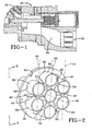
- Figure 1 is a partial cross section of a compressor, including a discharge for receiving a discharge muffler of the present invention.
- Figure 2 is a perspective view of a discharge muffler of the present invention.
- Figure 3 is an elevation view taken along view 3-3 from Figure 2 .
- Figure 4 is an enlarged partial cross section of a reflector fitted with an embodiment of a gasket of the present invention.
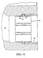
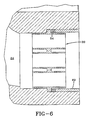
- Figures 5-6 are cross sections of vibrationally isolated muffler arrangements of the present invention.
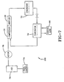
- Figure 7 is a schematic of a refrigeration system usable with the muffler of the present invention.
- a compressor 10 such as a screw compressor includes meshing rotors 22 that compress refrigerant vapor received at an inlet of the compressor, discharging the compressed vapor refrigerant at an outlet or discharge 24.
- Compressor 10 is installed in discharge 24 in fluid communication with the vapor refrigerant prior to the refrigerant vapor flowing toward other components in a heating, ventilation and air conditioning and refrigeration (HVAC&R) system.
- a plate or reflector 30 has a plurality of apertures 32 formed therein for receiving tubes, such as tubes 34, 38 and 42, and is preferably secured in discharge 24 by plurality of fasteners (not shown) inserted through peripherally disposed apertures 52.
- a plurality of vanes 46 is affixed to opposing sides of reflector 30.
- the tubes_34, 38, 42 and vanes 46 attenuate certain pressure pulsation frequencies generated by operation of the compressor 10 while improving compressor efficiency to be discussed in further detail below.
- Plate or reflector 30 is comprised of a material, such as metal, that can withstand pulsating pressurized refrigerant vapor discharged by compressor 10. Additionally, upon installation in the discharge 24, reflector 30 reflects a portion of the sound waves transmitted along discharge 24 while securing the plurality of tubes 34, 38 and 42 that are received in corresponding apertures 32 of the reflector 30.
- reflector 30 is circular, but can have any peripheral shape that is received in a preferably substantially fluid tight conformal arrangement in discharge 24, preferably with reflector 30 disposed substantially perpendicular to the direction of refrigerant flow. It is preferred that the proportion of surface area of reflector 30 disposed in fluid communication in discharge 24 remaining after subtracting the surface area of apertures 32 is about 1/3. For example, if the cross sectional area of discharge 24 is 20 square inches, the reflector 30 would cover approximately 7 square inches of discharge 24. However, it is to be understood that this proportion value is merely a guide, and that the proportion can be greater than or less than 1/3.
- reflector 30 may also be substantially vibrationally isolated from discharge 24.
- a gasket 54 can be disposed between reflector 30 and discharge 24, the gasket material preferably being a viscoelastic material, such as neoprene or other polymer, to damp vibrations that would other wise propagate from the reflector 30 to the compressor 10.
- the reflector 10 is also sufficiently resilient when compressed to provide a substantially fluid tight seal between the discharge 24 and the reflector 30.
- gasket 54 can have a U-shaped cross section (see Figure 4 ) having a pair of flanges 58 and an interconnecting web 56 disposed between the flanges 58 that can be secured to the periphery of the reflector 30.
- the gasket flanges 58 and web 56 can be independent from each other (see Figure 5 ), with a fitting 60, such as an annular shim, being used to apply a sufficient compressive force to secure the muffler 20 in position inside the discharge 24 while vibrationally isolating the muffler 20 from the discharge 24.
- gasket 54 can be a resilient cushion or spring, as shown in Figure 6 , although the cushion or spring can be located on either side or both sides of the reflector 30.
- tubes 34, 38 and 42 extend through reflector 30, with the centers of tubes 34 being aligned with a center line 36, tubes 38 aligned with a center line 40 and tubes 42 aligned with a center line 44.
- sound waves reflecting off of plate 30 strike and attenuate sound waves entering the tubes 34, 38 and 42, the sound waves preferably being plane-waves for the muffler 20 to function properly, as three dimensional waves behave differently than plane-waves.
- Tubes are sized (tuned) to attenuate sound frequencies associated with operation of the compressor 10 by making use of a relationship that exists between the diameter of the tubes and the plane-wave frequency which can be maintained in the tubes.
- plane-waves can exist in 6 inch diameter tubes (with R-134a refrigerant) only below 540 Hz.
- a tube having a 76.2 mm diameter maintains plane-waves up to twice the frequency of a 152.4 mm diameter, or 1,080 Hz. Since a sound frequency of 720 Hz is a problematic frequency in some compressor constructions, a tube diameter of about 114 mm which can maintain plane-waves at that frequency, may be desirable. Therefore, it is preferable to use multiple tubes having smaller diameters so that muffler performance can be enhanced.
- tube length is used to tune the tube to a particular frequency.
- a tube having a length of 44.5 mm, as measured from the surface of the plate 30 12.7 mm thick) to the end of the tube is tuned to 714 Hz.
- this tube is 102 mm long, so that the remainder of the tube extends past the other side of the plate by the same length.
- the plate 30 substantially bisects the tubes 34, 38 and 42.
- tubes 34, 38 and 42 are in substantially mutual axial alignment, running substantially perpendicular to the plate 30.
- adhesive, chemical or mechanical bonding techniques known in the art, including welding, can be employed.
- the tubes 34, 38 and 42 and the plate 30 can be of unitary construction.
- vanes 46 Preferably extending from each side of the plate 30 between adjacent tubes 34, 38 and 42 are vanes 46, the vanes 46 further preferably extending radially outward from a center tube 34.
- the vanes 46 attenuate higher sound frequencies than the tubes 34, 38 and 42, which is believed to result, at least in part, to result from the vanes 46 forming additional tuned cavities of smaller cross sectional areas than the tubes.
- a joint 50 can be formed to at least one side or to opposite sides of the vane 46. While the vanes 46 can define a profile having any closed geometry, an embodiment shown in Figure 2 includes a bevel 48 that provides enhanced structural stiffness and strength.
- apertures can be formed in either or both of the vanes 46 and the tubes 34, 38 and 42, which can affect sound attenuation. Additional apertures can also be formed in the plate 30, so long is there is sufficient proportional surface area to reflect sound waves as previously discussed.
- the tubes 34, 38 and 42 and vanes 46 are symmetric about a center axis 62 (see Figure 2 ), each tube being substantially the same length and diameter and each vane 46 being substantially identical, it is to be understood that such symmetry is not required, as even a centered tube on the plate 30 is not required, nor is it required that the tubes or vanes be of identical construction.
- the tubes may define any closed geometric shape and have different lengths, and smaller tubes may be nested inside larger tubes, if desired.
- tubes 34, 38 and 42, plate 30 and vanes 46 are preferably of integral metal construction, such as a welding, or alternately, unitary machined construction, such as casting, other compatible materials of sufficient strength, acoustic behavior and durability may also be used that can permit a molded construction.
- Test results were conducted using an embodiment of the muffler 20 as shown in Figure 2 on a conventional screw compressor wherein the reflector 30 had a reflective surface area proportion of approximately 1/3, as previously discussed.
- the resultant pressure drop of the discharged refrigerant vapor due to the muffler was only about 0.034 atm.
- an improvement in HVAC system performance of about 0.5 percent was observed while simultaneously providing an amount of sound attenuation comparable to that achieved by a conventional muffler.
- FIG. 7 illustrates generally one embodiment of the present invention incorporated in a refrigeration system.
- a HVAC, refrigeration or liquid chiller system 100 includes the compressor 10 having the muffler 20 as previously discussed, a condenser arrangement 70, expansion devices, a water chiller or evaporator arrangement 72 and a control panel 74.
- the control panel 74 controls operation of the refrigeration system 100.
- the control panel 74 can also be used to control the operation of a driving device, such as a variable speed drive or VSD 104, a motor 78 and the compressor 10.
- a conventional HVAC, refrigeration or liquid chiller system 100 includes many other features that are not shown in Figure 7 . These features have been purposely omitted to simplify the drawing for ease of illustration.
- the compressor 10 compresses a refrigerant vapor and delivers it to the condenser 70 after the flow of the refrigerant vapor has been improved by the muffler 20 as previously discussed.
- the refrigerant vapor delivered to the condenser 70 enters into a heat exchange relationship with a fluid, e.g., air or water, and undergoes a phase change to a refrigerant liquid as a result of the heat exchange relationship with the fluid.
- the condensed liquid refrigerant from condenser 70 flows through corresponding expansion devices to an evaporator 72.
- the evaporator 72 can include connections for a supply line and a return line of a cooling load 80.
- a secondary liquid which is preferably water, but can be any other suitable secondary liquid, e.g., ethylene, calcium chloride brine or sodium chloride brine, travels into the evaporator 72 via return line and exits the evaporator 72 via supply line.
- the liquid refrigerant in the evaporator 72 enters into a heat exchange relationship with the secondary liquid to chill the temperature of the secondary liquid.
- the refrigerant liquid in the evaporator 72 undergoes a phase change to a refrigerant vapor as a result of the heat exchange relationship with the secondary liquid.
- the vapor refrigerant in the evaporator 72 then returns to the compressor 10 to complete the cycle. It is to be understood that any suitable configuration of condenser 70 and evaporator 72 can be used in the system 100, provided that the appropriate phase change of the refrigerant in the condenser 70 and evaporator 72 is obtained.
Landscapes
- Engineering & Computer Science (AREA)
- Mechanical Engineering (AREA)
- General Engineering & Computer Science (AREA)
- Compressor (AREA)
- Exhaust Silencers (AREA)
Applications Claiming Priority (2)
| Application Number | Priority Date | Filing Date | Title |
|---|---|---|---|
| US11/047,552 US7578659B2 (en) | 2005-01-31 | 2005-01-31 | Compressor discharge muffler |
| PCT/US2006/002958 WO2006083712A1 (en) | 2005-01-31 | 2006-01-25 | Compressor discharge muffler |
Publications (2)
| Publication Number | Publication Date |
|---|---|
| EP1844238A1 EP1844238A1 (en) | 2007-10-17 |
| EP1844238B1 true EP1844238B1 (en) | 2013-06-26 |
Family
ID=36336426
Family Applications (1)
| Application Number | Title | Priority Date | Filing Date |
|---|---|---|---|
| EP06719700.4A Expired - Fee Related EP1844238B1 (en) | 2005-01-31 | 2006-01-25 | Compressor discharge muffler |
Country Status (7)
| Country | Link |
|---|---|
| US (1) | US7578659B2 (enExample) |
| EP (1) | EP1844238B1 (enExample) |
| JP (1) | JP4796078B2 (enExample) |
| KR (1) | KR20070099053A (enExample) |
| CN (1) | CN101133252A (enExample) |
| TW (1) | TW200632218A (enExample) |
| WO (1) | WO2006083712A1 (enExample) |
Families Citing this family (14)
| Publication number | Priority date | Publication date | Assignee | Title |
|---|---|---|---|---|
| DE102005029760A1 (de) * | 2005-05-23 | 2006-11-30 | Bitzer Kühlmaschinenbau Gmbh | Kältemittelverdichter |
| JP2009281620A (ja) * | 2008-05-20 | 2009-12-03 | Sanden Corp | 冷凍回路 |
| US8591208B2 (en) * | 2009-06-24 | 2013-11-26 | Southwest Research Institute | Multi-frequency pulsation absorber at cylinder valve cap |
| US8016071B1 (en) * | 2010-06-21 | 2011-09-13 | Trane International Inc. | Multi-stage low pressure drop muffler |
| JP5707948B2 (ja) * | 2011-01-12 | 2015-04-30 | 株式会社豊田自動織機 | エアコンプレッサ |
| US9243543B2 (en) | 2012-12-07 | 2016-01-26 | Hanon Systems | Universal attenuation device for air-conditioning circuit |
| US10048151B2 (en) | 2013-08-16 | 2018-08-14 | Kevin Allan Dooley, Inc. | Systems and methods for control of motion sickness within a moving structure due to infrasound pressures |
| DK3091415T3 (en) * | 2013-08-16 | 2018-11-26 | Kevin Allan Dooley Inc | SYSTEMS AND METHODS FOR MANAGING INFRAL SOUND PRESSURE |
| CN104131963B (zh) * | 2014-07-11 | 2016-06-29 | 西安交通大学 | 一种用于压缩机的油气分离消声器 |
| US20160312773A1 (en) * | 2015-04-22 | 2016-10-27 | Trane International Inc. | Refrigerant Line Muffler |
| CN104832247B (zh) * | 2015-04-29 | 2017-05-03 | 麦克维尔空调制冷(武汉)有限公司 | 一种用于螺杆式机组的排气消声器 |
| KR102620362B1 (ko) * | 2016-08-31 | 2024-01-04 | 삼성전자주식회사 | 공기조화기 |
| CN109974379A (zh) * | 2017-12-27 | 2019-07-05 | 青岛海尔股份有限公司 | 冰箱 |
| CN115371297A (zh) | 2021-05-21 | 2022-11-22 | 开利公司 | 用于冷凝器的导流装置、具有其的冷凝器及制冷系统 |
Family Cites Families (84)
| Publication number | Priority date | Publication date | Assignee | Title |
|---|---|---|---|---|
| US2205899A (en) * | 1939-05-01 | 1940-06-25 | Burgess Battery Co | Silencing device for pulsating gases |
| US3066857A (en) * | 1960-05-18 | 1962-12-04 | Westinghouse Electric Corp | Motor compressor unit with reduced noise transmission |
| US3473479A (en) * | 1967-07-07 | 1969-10-21 | Superior Mfg Co | Barrel pump assembly |
| US3577891A (en) * | 1968-08-21 | 1971-05-11 | Hitachi Ltd | Swash plate compressor |
| US3698840A (en) | 1971-05-26 | 1972-10-17 | Tecumseh Products Co | Compressor muffler construction |
| US4033707A (en) | 1973-04-04 | 1977-07-05 | Atlas Industries, Inc. | Refrigeration compressor structures and their methods of construction |
| JPS569174Y2 (enExample) * | 1976-06-16 | 1981-02-27 | ||
| US4108276A (en) * | 1976-09-20 | 1978-08-22 | Nelson Industries, Inc. | Vent silencer |
| US4111278A (en) | 1977-02-09 | 1978-09-05 | Copeland Corporation | Discharge muffler |
| US4255940A (en) * | 1979-08-09 | 1981-03-17 | Parker-Hannifin Corporation | Discharge line filter-dryer |
| US4330239A (en) | 1979-10-10 | 1982-05-18 | Tecumseh Products Company | Compressor muffler |
| US4370104A (en) | 1980-07-22 | 1983-01-25 | White Consolidated Industries, Inc. | Suction muffler for refrigeration compressor |
| DE8024363U1 (de) | 1980-09-12 | 1980-12-11 | M.A.N. Maschinenfabrik Augsburg- Nuernberg Ag, 8900 Augsburg | Schalldaempfer fuer verdichteranlagen, insbesondere schraubenverdichter |
| JPS6338385Y2 (enExample) * | 1981-01-30 | 1988-10-11 | ||
| US4401418B1 (en) | 1981-04-29 | 1998-01-06 | White Consolidated Ind Inc | Muffler system for refrigeration compressor |
| DE3242858A1 (de) | 1982-09-02 | 1984-03-08 | Sanyo Electric Co., Ltd., Moriguchi, Osaka | Hermetisch abgedichteter motorkompressor |
| JPS60152077U (ja) * | 1984-03-21 | 1985-10-09 | 株式会社豊田自動織機製作所 | 斜板式圧縮機 |
| JPS6148991U (enExample) * | 1984-08-29 | 1986-04-02 | ||
| JPS62247196A (ja) | 1986-04-18 | 1987-10-28 | Matsushita Refrig Co | ロ−タリ圧縮機の吸入装置 |
| JPH03175177A (ja) | 1989-12-05 | 1991-07-30 | Matsushita Refrig Co Ltd | 密閉型電動圧縮機 |
| JPH0424679U (enExample) * | 1990-06-22 | 1992-02-27 | ||
| JPH0472474A (ja) | 1990-07-12 | 1992-03-06 | Matsushita Refrig Co Ltd | 冷媒圧縮機 |
| US5146764A (en) | 1990-07-25 | 1992-09-15 | York International Corporation | System and method for controlling a variable geometry diffuser to minimize noise |
| US5373119A (en) * | 1990-11-23 | 1994-12-13 | Kioritz Corporation | Exhaust muffler for internal combustion engine |
| US5248859A (en) * | 1991-03-25 | 1993-09-28 | Alexander Borla | Collector/muffler/catalytic converter exhaust systems for evacuating internal combustion engine cylinders |
| US5173034A (en) | 1991-07-18 | 1992-12-22 | White Consolidated Industries, Inc. | Discharge muffler for refrigeration compressor |
| FR2683614B1 (fr) * | 1991-11-13 | 1994-01-14 | Sextant Avionique | Dispositif de fixation d'une glace sur un support soumis a vibrations notamment un ecran de visualisation de planche de bord d'avion. |
| JPH05157046A (ja) | 1991-12-03 | 1993-06-22 | Matsushita Refrig Co Ltd | 密閉型電動圧縮機の消音装置 |
| US5205719A (en) | 1992-01-13 | 1993-04-27 | Copeland Corporation | Refrigerant compressor discharge muffler |
| IT1260703B (it) | 1992-07-03 | 1996-04-22 | Necchi Compressori | Silenziatore per motocompressori per apparati frigoriferi |
| IT230572Y1 (it) | 1992-12-21 | 1999-06-07 | Gold Star Co | Dispositivo di soppressione del rumore per un compressore ermetico a stantuffo |
| US5341654A (en) | 1993-04-16 | 1994-08-30 | Copeland Corporation | Suction gas conduit |
| US5435700A (en) * | 1993-04-24 | 1995-07-25 | Goldstar Co., Ltd. | Refrigerant suction and discharge apparatus for a hermetic compressor |
| JPH07133774A (ja) | 1993-11-09 | 1995-05-23 | Hitachi Ltd | オイルフリースクリュー圧縮機 |
| DE4411191C2 (de) | 1994-03-30 | 1997-05-15 | Danfoss Compressors Gmbh | Kältemittelkompressoranordnung |
| KR0143182B1 (ko) * | 1994-04-29 | 1998-08-01 | 김광호 | 압축기 |
| US5496156A (en) | 1994-09-22 | 1996-03-05 | Tecumseh Products Company | Suction muffler |
| US5507151A (en) | 1995-02-16 | 1996-04-16 | American Standard Inc. | Noise reduction in screw compressor-based refrigeration systems |
| US5583325A (en) | 1995-04-26 | 1996-12-10 | Carrier Corporation | Muffler with integral check valve |
| DE19522383C2 (de) | 1995-06-23 | 1997-06-19 | Danfoss Compressors Gmbh | Saugschalldämpfer für einen Kältemittelkompressor |
| KR0156720B1 (ko) | 1995-07-27 | 1999-03-20 | 김광호 | 왕복동형 압축기 |
| KR0175891B1 (ko) * | 1995-07-29 | 1999-10-01 | 윤종용 | 압축기 |
| US5705777A (en) | 1995-10-20 | 1998-01-06 | Carrier Corporation | Refrigeration compressor muffler |
| DE69730458T2 (de) | 1996-01-23 | 2005-01-13 | Matsushita Refrigeration Co., Kusatsu | Auspuffschalldämpfer für einen Verdichter |
| FR2746861B1 (fr) | 1996-03-29 | 1998-06-19 | Unite Hermetique | Systeme de silencieux d'aspiration pour motocompresseur de refrigeration |
| KR19980027501U (ko) * | 1996-11-16 | 1998-08-05 | 박병재 | 자동차의 연료탱크 구조 |
| US5780785A (en) * | 1997-03-12 | 1998-07-14 | Eckel; Alan | Acoustic absorption device and an assembly of such devices |
| KR100210091B1 (ko) * | 1997-03-14 | 1999-07-15 | 윤종용 | 압축기의 소음감쇠장치 |
| KR100269951B1 (ko) * | 1997-11-05 | 2000-10-16 | 배길성 | 압축기의 흡입 머플러 |
| US5936210A (en) | 1998-01-15 | 1999-08-10 | Maremont Exhaust Products, Inc. | High performance muffler |
| KR100288872B1 (en) | 1998-01-20 | 2001-02-12 | Samsung Electronics Co Ltd | Noise reduction apparatus for air conditioner outdoor unit |
| US6382931B1 (en) | 1998-02-24 | 2002-05-07 | Respironics, Inc. | Compressor muffler |
| US5996731A (en) | 1998-02-24 | 1999-12-07 | Czabala; Michael P. | Compressor muffler |
| JPH11315784A (ja) * | 1998-04-30 | 1999-11-16 | Tochigi Fuji Ind Co Ltd | 流体機械 |
| JP4180691B2 (ja) | 1998-06-09 | 2008-11-12 | 松下電器産業株式会社 | 圧縮機の消音装置 |
| FI113892B (fi) * | 1998-09-30 | 2004-06-30 | Metso Paper Inc | Reaktiivinen äänenvaimennin teollisuuden ilmakanavia varten ja sen käyttö |
| KR200234719Y1 (ko) | 1998-12-31 | 2002-02-28 | 구자홍 | 밀폐형압축기의토출소음저감장치 |
| KR100283653B1 (ko) | 1999-01-14 | 2001-02-15 | 윤종용 | 밀폐형 회전 압축기의 토출 머플러 |
| BR9900463A (pt) | 1999-02-26 | 2000-08-29 | Brasil Compressores Sa | Abafador de sucção para compressor hermético |
| DE19915918C2 (de) | 1999-04-09 | 2001-05-31 | Danfoss Compressors Gmbh | Kältemittelkompressor und Verfahren zu seiner Montage |
| JP3662813B2 (ja) | 1999-08-19 | 2005-06-22 | エルジー電子株式会社 | リニア圧縮機 |
| US6176688B1 (en) | 1999-10-12 | 2001-01-23 | Tecumseh Products Company | Discharge muffler arrangement |
| US6524080B2 (en) | 2000-04-11 | 2003-02-25 | R. K. Dewan & Co. | Hermetically sealed compressors |
| EP1276993A4 (en) | 2000-04-25 | 2003-10-29 | Lg Electronics Inc | COMPRESSOR |
| KR100378803B1 (ko) | 2000-06-12 | 2003-04-07 | 엘지전자 주식회사 | 압축기용 소음기 |
| US6488482B1 (en) | 2000-09-07 | 2002-12-03 | Donald Yannascoli | Integral compressor muffler |
| KR100364741B1 (ko) | 2000-09-28 | 2002-12-16 | 엘지전자 주식회사 | 압축기의 흡입 머플러 |
| US6558137B2 (en) | 2000-12-01 | 2003-05-06 | Tecumseh Products Company | Reciprocating piston compressor having improved noise attenuation |
| KR100373455B1 (ko) | 2000-12-21 | 2003-02-25 | 삼성광주전자 주식회사 | 압축기의 흡입머플러 |
| KR100386269B1 (ko) | 2001-01-11 | 2003-06-02 | 엘지전자 주식회사 | 압축기용 소음기 |
| US6547536B2 (en) | 2001-01-19 | 2003-04-15 | Samsung Kwangju Electronics., Ltd. | Reciprocating compressor having a discharge pulsation |
| KR100382453B1 (ko) | 2001-03-07 | 2003-05-09 | 삼성광주전자 주식회사 | 토출 맥동 저감구조를 갖는 압축기 |
| CN1318758C (zh) | 2001-06-08 | 2007-05-30 | 巴西船用压缩机有限公司 | 用于往复式气密压缩机的真空消音器 |
| DE10128225C1 (de) | 2001-06-11 | 2002-12-05 | Danfoss Compressors Gmbh | Saugschalldämpfer |
| KR100448547B1 (ko) * | 2001-08-17 | 2004-09-13 | 삼성광주전자 주식회사 | 왕복동식 밀폐형 압축기 |
| US6840746B2 (en) | 2002-07-02 | 2005-01-11 | Bristol Compressors, Inc. | Resistive suction muffler for refrigerant compressors |
| CN100350158C (zh) | 2002-08-23 | 2007-11-21 | 约克国际公司 | 用于探测离心压缩机内的旋转失速的系统和方法 |
| KR100687639B1 (ko) | 2002-09-02 | 2007-02-27 | 한라공조주식회사 | 압축기 |
| DE10244565B4 (de) | 2002-09-25 | 2004-07-22 | Danfoss Compressors Gmbh | Zylinderkopfanordnung für einen Kolbenverdichter |
| DE10248183A1 (de) | 2002-10-16 | 2004-04-29 | Wabco Gmbh & Co. Ohg | Geräuschdämpfungseinrichtung für Luftpresser |
| KR100498376B1 (ko) | 2002-11-19 | 2005-07-01 | 엘지전자 주식회사 | 스크롤 압축기 및 스크롤 압축기 제조방법 |
| US7229257B2 (en) | 2003-02-07 | 2007-06-12 | Lg Electronics Inc. | Horizontal type compressor |
| KR100504445B1 (ko) | 2003-03-05 | 2005-08-01 | 삼성광주전자 주식회사 | 압축기용 실린더 조립체, 압축기 및 압축기가 적용된냉매순환회로를 가지는 장치 |
| KR100504983B1 (ko) | 2003-03-12 | 2005-08-01 | 삼성광주전자 주식회사 | 압축기용 흡입머플러, 압축기 및 냉매순환회로를 가지는장치 |
-
2005
- 2005-01-31 US US11/047,552 patent/US7578659B2/en active Active
-
2006
- 2006-01-20 TW TW095102251A patent/TW200632218A/zh unknown
- 2006-01-25 WO PCT/US2006/002958 patent/WO2006083712A1/en not_active Ceased
- 2006-01-25 KR KR1020077019796A patent/KR20070099053A/ko not_active Ceased
- 2006-01-25 JP JP2007553268A patent/JP4796078B2/ja not_active Expired - Fee Related
- 2006-01-25 CN CNA2006800063095A patent/CN101133252A/zh active Pending
- 2006-01-25 EP EP06719700.4A patent/EP1844238B1/en not_active Expired - Fee Related
Also Published As
| Publication number | Publication date |
|---|---|
| KR20070099053A (ko) | 2007-10-08 |
| TW200632218A (en) | 2006-09-16 |
| EP1844238A1 (en) | 2007-10-17 |
| US7578659B2 (en) | 2009-08-25 |
| JP4796078B2 (ja) | 2011-10-19 |
| JP2008528869A (ja) | 2008-07-31 |
| CN101133252A (zh) | 2008-02-27 |
| WO2006083712A1 (en) | 2006-08-10 |
| US20060171819A1 (en) | 2006-08-03 |
Similar Documents
| Publication | Publication Date | Title |
|---|---|---|
| EP1844238B1 (en) | Compressor discharge muffler | |
| US8016071B1 (en) | Multi-stage low pressure drop muffler | |
| JP5866004B2 (ja) | 密閉形圧縮機及びヒートポンプ装置 | |
| CN101466949A (zh) | 用于制冷压缩机的声学消声器中的谐振器装置 | |
| US20070204927A1 (en) | Flow Path Device, Refrigerating Cycle Device, Pressure Pulsation Reducing Device, and Pressure Pulsation Reducing Method | |
| US20050194207A1 (en) | Apparatus and method of sound attenuation in a system employing a VSD and a quarter-wave resonator | |
| EP3850281B1 (en) | Oil separator with integrated muffler | |
| US10890188B2 (en) | Compressor noise reduction | |
| WO2024169977A1 (zh) | 螺杆压缩机 | |
| CN115419600B (zh) | 消声器和具有该消声器的制冷系统 | |
| US7988427B2 (en) | Compressor muffler | |
| WO2008098330A2 (en) | Constructive arrangement of an acoustic filter for a refrigeration compressor | |
| CN113898558A (zh) | 消音器、压缩机和制冷设备 | |
| EP4045798A1 (en) | Screw compressor | |
| EP3828413B1 (en) | Heat pump comprising a muffler | |
| JPH09250844A (ja) | 冷凍サイクル | |
| CN218376902U (zh) | 压缩机 | |
| CN210463275U (zh) | 空调器 | |
| CN120444680A (zh) | 压缩机集成系统、空调室外机及暖通设备 | |
| CN106662371A (zh) | 用于蒸气压缩系统的脉动阻尼器 | |
| WO2021074806A1 (en) | Screw compressor | |
| CN120292602A (zh) | 压缩机集成系统、空调室外机及暖通设备 | |
| CN114017343A (zh) | 一种旋转式压缩机及制冷设备 | |
| CN114017336A (zh) | 压缩机及制冷设备 | |
| HK1022513B (en) | Silencer and air conditioner |
Legal Events
| Date | Code | Title | Description |
|---|---|---|---|
| PUAI | Public reference made under article 153(3) epc to a published international application that has entered the european phase |
Free format text: ORIGINAL CODE: 0009012 |
|
| 17P | Request for examination filed |
Effective date: 20070723 |
|
| AK | Designated contracting states |
Kind code of ref document: A1 Designated state(s): DE GB |
|
| RBV | Designated contracting states (corrected) |
Designated state(s): DE GB |
|
| DAX | Request for extension of the european patent (deleted) | ||
| 17Q | First examination report despatched |
Effective date: 20120402 |
|
| GRAP | Despatch of communication of intention to grant a patent |
Free format text: ORIGINAL CODE: EPIDOSNIGR1 |
|
| GRAS | Grant fee paid |
Free format text: ORIGINAL CODE: EPIDOSNIGR3 |
|
| GRAA | (expected) grant |
Free format text: ORIGINAL CODE: 0009210 |
|
| AK | Designated contracting states |
Kind code of ref document: B1 Designated state(s): DE GB |
|
| REG | Reference to a national code |
Ref country code: GB Ref legal event code: FG4D |
|
| REG | Reference to a national code |
Ref country code: DE Ref legal event code: R096 Ref document number: 602006036985 Country of ref document: DE Effective date: 20130822 |
|
| PGFP | Annual fee paid to national office [announced via postgrant information from national office to epo] |
Ref country code: DE Payment date: 20140127 Year of fee payment: 9 |
|
| PLBE | No opposition filed within time limit |
Free format text: ORIGINAL CODE: 0009261 |
|
| STAA | Information on the status of an ep patent application or granted ep patent |
Free format text: STATUS: NO OPPOSITION FILED WITHIN TIME LIMIT |
|
| 26N | No opposition filed |
Effective date: 20140327 |
|
| PGFP | Annual fee paid to national office [announced via postgrant information from national office to epo] |
Ref country code: GB Payment date: 20140123 Year of fee payment: 9 |
|
| REG | Reference to a national code |
Ref country code: DE Ref legal event code: R097 Ref document number: 602006036985 Country of ref document: DE Effective date: 20140327 |
|
| REG | Reference to a national code |
Ref country code: DE Ref legal event code: R119 Ref document number: 602006036985 Country of ref document: DE |
|
| GBPC | Gb: european patent ceased through non-payment of renewal fee |
Effective date: 20150125 |
|
| PG25 | Lapsed in a contracting state [announced via postgrant information from national office to epo] |
Ref country code: GB Free format text: LAPSE BECAUSE OF NON-PAYMENT OF DUE FEES Effective date: 20150125 Ref country code: DE Free format text: LAPSE BECAUSE OF NON-PAYMENT OF DUE FEES Effective date: 20150801 |