EP1840442B1 - Joint member for pipe joint - Google Patents
Joint member for pipe joint Download PDFInfo
- Publication number
- EP1840442B1 EP1840442B1 EP05820188.0A EP05820188A EP1840442B1 EP 1840442 B1 EP1840442 B1 EP 1840442B1 EP 05820188 A EP05820188 A EP 05820188A EP 1840442 B1 EP1840442 B1 EP 1840442B1
- Authority
- EP
- European Patent Office
- Prior art keywords
- annular
- valve
- coupling member
- valve seat
- seat surface
- Prior art date
- Legal status (The legal status is an assumption and is not a legal conclusion. Google has not performed a legal analysis and makes no representation as to the accuracy of the status listed.)
- Expired - Lifetime
Links
Images

Classifications
-
- F—MECHANICAL ENGINEERING; LIGHTING; HEATING; WEAPONS; BLASTING
- F16—ENGINEERING ELEMENTS AND UNITS; GENERAL MEASURES FOR PRODUCING AND MAINTAINING EFFECTIVE FUNCTIONING OF MACHINES OR INSTALLATIONS; THERMAL INSULATION IN GENERAL
- F16L—PIPES; JOINTS OR FITTINGS FOR PIPES; SUPPORTS FOR PIPES, CABLES OR PROTECTIVE TUBING; MEANS FOR THERMAL INSULATION IN GENERAL
- F16L37/00—Couplings of the quick-acting type
- F16L37/28—Couplings of the quick-acting type with fluid cut-off means
- F16L37/30—Couplings of the quick-acting type with fluid cut-off means with fluid cut-off means in each of two pipe-end fittings
- F16L37/32—Couplings of the quick-acting type with fluid cut-off means with fluid cut-off means in each of two pipe-end fittings at least one of two lift valves being opened automatically when the coupling is applied
- F16L37/34—Couplings of the quick-acting type with fluid cut-off means with fluid cut-off means in each of two pipe-end fittings at least one of two lift valves being opened automatically when the coupling is applied at least one of the lift valves being of the sleeve type, i.e. a sleeve being telescoped over an inner cylindrical wall
-
- Y—GENERAL TAGGING OF NEW TECHNOLOGICAL DEVELOPMENTS; GENERAL TAGGING OF CROSS-SECTIONAL TECHNOLOGIES SPANNING OVER SEVERAL SECTIONS OF THE IPC; TECHNICAL SUBJECTS COVERED BY FORMER USPC CROSS-REFERENCE ART COLLECTIONS [XRACs] AND DIGESTS
- Y10—TECHNICAL SUBJECTS COVERED BY FORMER USPC
- Y10T—TECHNICAL SUBJECTS COVERED BY FORMER US CLASSIFICATION
- Y10T137/00—Fluid handling
- Y10T137/8593—Systems
- Y10T137/87917—Flow path with serial valves and/or closures
- Y10T137/87925—Separable flow path section, valve or closure in each
- Y10T137/87941—Each valve and/or closure operated by coupling motion
- Y10T137/87949—Linear motion of flow path sections operates both
- Y10T137/87957—Valves actuate each other
Definitions
- the present invention relates to a coupling member of a pipe coupling having a male coupling member and a female coupling member according to the preamble of claim 1.
- a coupling is known from US 2461705 .
- Other prior art comprises US508564 , GB2241034 , US2002/148514 and JP2002106773 .
- a male coupling member and a female coupling member of a pipe coupling are commonly equipped with an on-off valve that closes a fluid passage formed through the male and female coupling members to prevent fluid from flowing out therefrom when the coupling members are decoupled from each other.
- an on-off valve that closes a fluid passage formed through the male and female coupling members to prevent fluid from flowing out therefrom when the coupling members are decoupled from each other.
- the fluid rapidly flows around the on-off valve as it slightly opens.
- Such rapid flow of fluid creates a negative pressure around the surface of the on-off valve that has just separated from the associated annular valve seat surface.
- the negative pressure causes a seal ring provided on the valve surface to be deformed toward the fluid passage. The seal ring thus deformed is subjected to excessive force from the fluid and hence likely to separate from the on-off valve.
- Patent Document 1 Japanese Utility Model Registration Application Publication No. Sho 50-124624
- an object of the present invention is to provide a coupling member adapted to minimize the occurrence of separation of the seal ring by the rapid flow of fluid around the on-off valve when it is opened.
- Fig. 1 shows a seal ring 12 used in a conventional on-off valve 10, that is, a seal ring with a rectangular section that is fitted and fixed in an annular groove 16 formed on a valve head 14.
- the inventor of this application considered that the configuration of this seal ring also relates to the separation of the seal ring, and improved the seal ring configuration to provide a pipe coupling adapted so that separation of the seal ring is unlikely to occur.
- the present invention provides a coupling member of a pipe coupling having a male coupling member and a female coupling member that are couplable to each other according to claim 1.
- the coupling member may be arranged as follows.
- the annular valve seat surface has an annular sealing valve seat surface that is sealingly engaged by the seal ring when the on-off valve is in the closed position.
- the annular valve seat surface further has an annular forward valve seat surface and an annular rear valve seat surface located forward and rearward, respectively, of the annular sealing valve seat surface.
- the annular rear valve seat surface has a rear axial surface that extends substantially parallel to the axis.
- the present invention provides a coupling member of a pipe coupling having a male coupling member and a female coupling member that are couplable to each other.
- the coupling member includes a tubular member having a fluid passage.
- the tubular member has an annular valve seat surface formed so as to surround the fluid passage.
- An on-off valve is provided in the fluid passage of the tubular member.
- the on-off valve is movable between a closed position where it is engaged under pressure with the annular valve seat surface to close the fluid passage and an open position where the on-off valve is displaced rearward in the axial direction of the fluid passage to separate from the annular valve seat surface, thereby opening the fluid passage.
- the on-off valve has an annular valve surface facing the annular valve seat surface.
- a seal ring is provided on the annular valve surface.
- the annular valve surface has a forward annular valve surface portion located forward of the seal ring.
- the forward annular valve surface portion has a forward annular passage limiting portion adapted to be in contact with or close proximity to the annular valve seat surface.
- the coupling member may be arranged as follows.
- the annular valve seat surface has an annular sealing valve seat surface that is sealingly engaged by the seal ring when the on-off valve is in the closed position.
- the annular valve seat surface further has an annular forward valve seat surface and an annular rear valve seat surface located forward and rearward, respectively, of the annular sealing valve seat surface.
- the annular forward valve seat surface has a forward axial surface that extends substantially parallel to the axis.
- the coupling member may be arranged as follows.
- the annular valve surface has an annular groove formed between the forward annular valve surface portion and the rear annular valve surface portion.
- the seal ring is fitted and fixed in the annular groove.
- the annular groove has a forward annular groove portion and a rear annular groove portion shallower than the forward annular groove portion.
- the rear annular valve surface portion of the annular valve surface has a larger radius than that of the forward annular valve surface portion.
- the seal ring has a forward annular seal portion fitted in the forward annular groove portion and having a larger radius than that of the forward annular valve surface portion of the annular valve surface.
- the seal ring further has a rear annular seal portion contiguous with the forward annular seal portion and having an outer diameter that is substantially the same as that of the forward annular seal portion but smaller than that of the rear annular valve surface portion.
- the rear annular seal portion is fitted and fixed in the rear annular groove portion.
- the coupling member may be arranged as follows.
- the rear annular groove portion has a rear extension groove portion extending rearward by a predetermined length at a position radially inward of the rear annular valve surface portion of the annular valve surface.
- the rear annular seal portion extends to be fitted and fixed in the rear extension groove portion of the rear annular groove portion.
- the coupling member may be arranged as follows.
- the annular valve surface has an annular groove formed between the forward annular valve surface portion and the rear annular valve surface portion.
- the seal ring is fitted and fixed in the annular groove.
- the annular groove has a forward annular groove portion, a rear annular groove portion, and an annular raised portion raised between the forward and rear annular groove portions.
- the annular raised portion has substantially the same radius as that of the forward annular valve surface portion.
- the seal ring has a U-shape in a section containing the axis and has an outer diameter larger than that of the forward annular valve surface portion but smaller than that of the rear annular valve surface portion.
- the present invention provides a coupling member of a pipe coupling having a male coupling member and a female coupling member that are couplable to each other.
- the coupling member includes a tubular member having a fluid passage.
- the tubular member has an annular valve seat surface formed so as to surround the fluid passage.
- An on-off valve is provided in the fluid passage of the tubular member.
- the on-off valve is movable between a closed position where it is engaged under pressure with the annular valve seat surface to close the fluid passage and an open position where the on-off valve is displaced rearward in the axial direction of the fluid passage to separate from the annular valve seat surface, thereby opening the fluid passage.
- the on-off valve has an annular valve surface facing the annular valve seat surface.
- a seal ring is fitted and fixed in an annular groove formed on the annular valve surface.
- the annular groove has a forward annular groove portion and a rear annular groove portion shallower than the forward annular groove portion.
- the annular valve surface has a forward annular valve surface portion contiguous with and extending forward from the forward annular groove portion.
- the annular valve surface further has a rear annular valve surface portion contiguous with and extending rearward from the rear annular groove portion.
- the rear annular valve surface portion has a larger radius than that of the forward annular valve surface portion.
- the seal ring has a forward annular seal portion fitted in the forward annular groove portion and having a larger outer diameter than that of the forward annular valve surface portion of the annular valve surface.
- the seal ring further has a rear annular seal portion contiguous with the forward annular seal portion and having an outer diameter that is substantially the same as that of the forward annular seal portion but smaller than that of the rear annular valve surface portion.
- the rear annular seal portion is fitted and fixed in the rear annular groove portion.
- the coupling member may be arranged as follows.
- the rear annular groove portion of the annular groove has a rear extension groove portion extending rearward by a predetermined length at a position radially inward of the rear annular valve surface portion.
- the rear annular seal portion extends to be fitted and fixed in the rear extension groove portion.
- the present invention provides a coupling member of a pipe coupling having a male coupling member and a female coupling member that are couplable to each other.
- the coupling member includes a tubular member having a fluid passage.
- the tubular member has an annular valve seat surface formed so as to surround the fluid passage.
- An on-off valve is provided in the fluid passage of the tubular member.
- the on-off valve is movable between a closed position where it is engaged under pressure with the annular valve seat surface to close the fluid passage and an open position where the on-off valve is displaced rearward in the axial direction of the fluid passage to separate from the annular valve seat surface, thereby opening the fluid passage.
- the on-off valve has an annular valve surface facing the annular valve seat surface.
- a seal ring is fitted and fixed in an annular groove formed on the annular valve surface.
- the annular valve surface has a forward annular valve surface portion and a rear annular valve surface portion that are located forward and rearward, respectively, of the annular groove.
- the annular groove has a forward annular groove portion, a rear annular groove portion, and an annular raised portion raised between the forward and rear annular groove portions.
- the annular raised portion has substantially the same radius as that of the forward annular valve surface portion.
- the seal ring is fitted and fixed in the annular groove and has a U-shape in a section containing the axis and an outer diameter larger than that of the forward annular valve surface portion but smaller than that of the rear annular valve surface portion.
- the forward annular passage limiting portion or the rear annular passage limiting portion of the on-off valve is moved while keeping in contact with or close proximity to the annular valve seat surface until the on-off valve reaches a position where it substantially opens the fluid passage, as stated above. Therefore, the flow of fluid flowing around the seal ring of the on-off valve is limited.
- the forward annular passage limiting portion and/or the rear annular passage limiting portion separates from the annular valve seat surface and, consequently, a large amount of fluid flows around the seal ring of the on-off valve, the cross-section of the fluid passage around the seal ring has already become larger than a specific size. Accordingly, there is no excessive force that would otherwise be applied to the seal ring. Thus, separation of the seal ring can be prevented.
- the rear annular groove portion is shallower than the forward annular groove portion. Separation of the seal ring starts from the rear annular seal portion fixed in the rear annular groove portion.
- the radial wall thickness of the rear annular seal portion of the seal ring, which is fitted in the rear annular groove portion is reduced. Consequently, even if excessive force is applied to the rear annular seal portion by rapid flow of fluid, deformation of the seal portion is smaller than in the conventional on-off valve as shown in Fig. 1 . Accordingly, separation of the seal ring becomes unlikely to occur.
- the rear annular seal portion fitted in the rear annular groove portion is held and fixed between the annular raised portion and the rear annular valve surface portion. Therefore, deformation of the seal ring due to force applied thereto from the fluid is minimized. Accordingly, separation of the seal ring can be prevented.
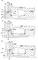
- Fig. 2 shows a female coupling member 22 and a male coupling member 24 of a pipe coupling 20 according to the present invention in a state where the coupling members 22 and 24 are disconnected from each other.
- Fig. 3 shows a state where the female coupling member 22 and the male coupling member 24 are coupled to each other.
- Figs. 4 to 7 show the movement of an on-off valve 26 of the female coupling member 22 during coupling of the female coupling member 22 to the male coupling member 24.
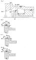
- Figs. 8 to 10 show various embodiments of a seal ring 50 of the on-off valve 26.
- the female coupling member 22 has a tubular member 32 with a fluid passage 30 and an on-off valve 26 provided in the fluid passage 30 of the tubular member 32.
- An annular valve seat surface 34 is formed on the inner peripheral surface of the tubular member 32 so as to surround the fluid passage 30.
- the on-off valve 26 is movable between a closed position ( Fig. 2 ) where it is engaged under pressure with the annular valve seat surface 34 to close the fluid passage 30 and an open position ( Fig. 3 ) where the on-off valve 26 is displaced rearward in the axial direction of the fluid passage 30 to separate from the annular valve seat surface 34, thereby opening the fluid passage 30.
- the male coupling member 24 has a tubular member 42 with a fluid passage 40 and a fixed valve member 44 extending along the axis of the tubular member 42 and fixedly secured to the tubular member 42.
- the male coupling member 24 further has a tubular movable valve member 46 slidably provided in the tubular member 42.
- the movable valve member 46 is movable between a closed position ( Fig. 2 ) where it sealingly engages the fixed valve member 44 to close the fluid passage 40 and an open position ( Fig. 3 ) where the movable valve member 46 is displaced rearward from the closed position to open the fluid passage 40.
- the on-off valve 26 of the female coupling member 22 has an annular valve surface 48 facing the annular valve seat surface 34 and a seal ring 50 provided on the annular valve surface 48.
- the annular valve surface 48 has a forward annular valve surface portion 52 located forward of the seal ring 50 and a rear annular valve surface portion 54 located rearward of the seal ring 50.
- the forward annular valve surface portion 52 and the rear annular valve surface portion 54 respectively have a forward annular passage limiting portion 56 and a rear annular passage limiting portion 58 that are adapted to be substantially in contact with the annular valve seat surface 34.
- the annular valve seat surface 34 has an annular sealing valve seat surface 34-1. that is sealingly engaged by the seal ring 50 when the on-off valve 26 is in the closed position.
- the annular valve seat surface 34 further has an annular forward valve seat surface 34-2 and an annular rear valve seat surface 34-3 located forward and rearward, respectively, of the annular sealing valve seat surface 34-1.
- the annular forward and rear valve seat surfaces 34-2 and 34-3 respectively have a forward axial surface 34-2' and a rear axial surface 34-3' that extend substantially parallel to the axis of the tubular member 32.
- the annular valve surface 48 of the on-off valve 26 has an annular groove 60 formed between the forward and rear annular valve surface portions 52 and 54.
- the seal ring 50 is fitted and fixed in the annular groove 60.
- the annular groove 60 has a forward annular groove portion 60-1 and a rear annular groove portion 60-2 shallower than the forward annular groove portion 60-1.
- the rear annular valve surface portion 54 of the annular valve surface 48 has a larger radius than that of the forward annular valve surface portion 52.
- the seal ring 50 has a forward annular seal portion 50-1 ( Fig. 5 ) fitted in the forward annular groove portion 60-1 and having a larger radius than that of the forward annular valve surface portion 52 of the annular valve surface 48.
- the seal ring 50 further has a rear annular seal portion 50-2 contiguous with the forward annular seal portion 50-1 and having an outer diameter that is substantially the same as that of the forward annular seal portion 50-1 but smaller than that of the rear annular valve surface portion 54.
- the rear annular seal portion 50-2 is fitted and fixed in the rear annular groove portion 60-2.
- the forward annular passage limiting portion 56 and the rear annular passage limiting portion 58 are moved while keeping substantially in contact with the forward axial surface 34-2' and the rear axial surface 34-3', respectively, as shown in Figs. 5 and 6 .
- the forward annular passage limiting portion 56 and the rear annular passage limiting portion 58 are, as shown in Figs.
- the seal ring 50 has a reduced radial wall thickness at the rear annular seal portion 50-2. Therefore, the amount to which the seal ring 50 is deformed radially outward by the force applied thereto from the fluid is reduced, and the occurrence of separation of the seal ring 50 is minimized.
- Figs. 8 to 10 show modifications of the seal ring 50 and the annular groove 60.
- Fig. 8 shows a modification in which the rear annular groove portion 60-2 has a rear extension groove portion 60-3 extending rearward by a predetermined length at a position radially inward of the rear annular valve surface portion 54 of the annular valve surface, and the rear annular seal portion 50-2 extends to be fitted and fixed in the rear extension groove portion 60-3 of the rear annular groove portion 60-2.
- This structure can offer increased resistance to the seal ring separating force applied by the flow of fluid.
- the modification shown in Fig. 9 is substantially the same as the modification shown in Fig. 8 except that the rear extension groove portion 60-3 and the rear annular seal portion 50-2 fitted therein are slightly modified in shape.
- Fig. 10 shows a modification in which the annular groove 60 of the on-off valve 26 has a forward annular groove portion 60-1, a rear annular groove portion 60-2, and an annular raised portion 60-4 raised between the two annular groove portions 60-1 and 60-2, and the annular raised portion 60-4 has substantially the same radius as that of the forward annular valve surface portion 52.
- the seal ring 50 has a U-shape in a section containing the axis of the fluid passage 30. The outer diameter of the seal ring 50 is larger than that of the forward annular valve surface portion 52 but smaller than that of the rear annular valve surface portion 54.
- the rear annular seal portion 50-2 which is fitted in the rear annular groove portion 60-2, is held and fixed between the annular raised portion and the rear valve surface portion. Therefore, the deformation of the seal ring 50 due to the negative pressure applied thereto from the fluid is minimized. Accordingly, separation of the seal ring 50 can be prevented.
- the present invention is not necessarily limited to the described embodiments.
- the present invention is also applicable to a male coupling member.
- the configuration of the seal ring can be modified in a variety of ways. For example, the wall thickness of the rear annular seal portion 50-2, which is likely to separate, may be reduced.
Landscapes
- Engineering & Computer Science (AREA)
- General Engineering & Computer Science (AREA)
- Mechanical Engineering (AREA)
- Quick-Acting Or Multi-Walled Pipe Joints (AREA)
Applications Claiming Priority (2)
| Application Number | Priority Date | Filing Date | Title |
|---|---|---|---|
| JP2004381060A JP4499553B2 (ja) | 2004-12-28 | 2004-12-28 | 管継手の継手部材 |
| PCT/JP2005/023706 WO2006077716A1 (ja) | 2004-12-28 | 2005-12-26 | 管継手の継手部材 |
Publications (3)
| Publication Number | Publication Date |
|---|---|
| EP1840442A1 EP1840442A1 (en) | 2007-10-03 |
| EP1840442A4 EP1840442A4 (en) | 2011-12-07 |
| EP1840442B1 true EP1840442B1 (en) | 2016-03-02 |
Family
ID=36692107
Family Applications (1)
| Application Number | Title | Priority Date | Filing Date |
|---|---|---|---|
| EP05820188.0A Expired - Lifetime EP1840442B1 (en) | 2004-12-28 | 2005-12-26 | Joint member for pipe joint |
Country Status (4)
| Country | Link |
|---|---|
| US (1) | US7708029B2 (enExample) |
| EP (1) | EP1840442B1 (enExample) |
| JP (1) | JP4499553B2 (enExample) |
| WO (1) | WO2006077716A1 (enExample) |
Families Citing this family (23)
| Publication number | Priority date | Publication date | Assignee | Title |
|---|---|---|---|---|
| JP3909339B1 (ja) * | 2006-11-17 | 2007-04-25 | 日東工器株式会社 | 管継手の継手部材 |
| JP5117830B2 (ja) * | 2007-11-27 | 2013-01-16 | ブリヂストンフローテック株式会社 | 弁付管継手 |
| JP5188787B2 (ja) * | 2007-11-27 | 2013-04-24 | ブリヂストンフローテック株式会社 | 弁付管継手 |
| JP2009127797A (ja) * | 2007-11-27 | 2009-06-11 | Bridgestone Flowtech Corp | 弁付管継手 |
| US8720487B2 (en) * | 2010-10-19 | 2014-05-13 | Robert Charles Cooley | Grease delivery receiver and nozzle couplable without fluid pressure bleed-down and having pressurization lockout and flush face coupling |
| DE102011015604B4 (de) * | 2011-03-30 | 2013-10-02 | Voswinkel Entwicklungs- Und Verwaltungs-Gmbh & Co. Kg | Kupplungsteil einer Druckmittel-Leitungskupplung sowie Ventilkörper für ein Kupplungsteil |
| JP5394460B2 (ja) * | 2011-09-22 | 2014-01-22 | 長堀工業株式会社 | 流体継手 |
| US20130312846A1 (en) * | 2012-05-25 | 2013-11-28 | André Sloth Eriksen | Fluid connector for a cooling system |
| US9016314B2 (en) | 2012-05-25 | 2015-04-28 | Asatek Danmark A/S | Fluid connector for a cooling system |
| US9803787B2 (en) | 2012-09-14 | 2017-10-31 | The United States Of America, As Represented By The Secretary Of The Navy | Magnetically attracted fluid transfer system |
| CN105143748A (zh) * | 2013-03-15 | 2015-12-09 | 可得制品公司 | 低泄漏联接组件 |
| US11067210B2 (en) | 2013-03-15 | 2021-07-20 | Colder Products Company | Low-spill coupling assembly |
| USD830524S1 (en) | 2014-03-14 | 2018-10-09 | Colder Products Company | Coupling |
| DE102014009046A1 (de) * | 2014-06-18 | 2015-12-24 | Voswinkel Entwicklungs- Und Verwaltungs-Gmbh & Co. Kg | Kupplungsteil für eine Schnellkupplung für Hochdruckhydraulikleitungen |
| JP6328691B2 (ja) * | 2016-05-23 | 2018-05-23 | 日東工器株式会社 | バルブ構造及びそれを備えた雌型及び雄型管継手 |
| JP6764283B2 (ja) * | 2016-08-12 | 2020-09-30 | 株式会社ブリヂストン | 弁体、弁体の製造方法、及び管継手 |
| JP2018123848A (ja) * | 2017-01-30 | 2018-08-09 | ニッタ株式会社 | 管継手 |
| DE102019116439A1 (de) * | 2019-06-05 | 2020-12-10 | Schaeffler Technologies AG & Co. KG | Kopplungsanordnung für eine Hydraulikeinrichtung und Verfahren zur Kopplung und strömungstechnischen Verbindung einer ersten und zweiten Kopplungskomponente der Kopplungsanordnung |
| CN110500463B (zh) * | 2019-07-17 | 2021-08-20 | 华为技术有限公司 | 一种接头、冷却系统和计算机装置 |
| JP2021169846A (ja) * | 2020-04-16 | 2021-10-28 | ニッタ株式会社 | 雄継手及び管継手 |
| FR3128001B1 (fr) * | 2021-10-13 | 2023-10-27 | Staubli Sa Ets | Raccord rapide et ensemble de connexion comprenant un tel raccord rapide |
| US20250020254A1 (en) * | 2023-07-12 | 2025-01-16 | Blue Origin, Llc | Quick disconnect coupling systems and related methods |
| TWI897497B (zh) * | 2024-06-27 | 2025-09-11 | 富世達股份有限公司 | 液流接頭結構 |
Family Cites Families (30)
| Publication number | Priority date | Publication date | Assignee | Title |
|---|---|---|---|---|
| US2299193A (en) * | 1941-01-29 | 1942-10-20 | Bendix Aviat Corp | Coupling |
| US2425500A (en) * | 1943-07-07 | 1947-08-12 | Wiggins Irene Lane | Valved coupling |
| US2451441A (en) * | 1945-03-28 | 1948-10-12 | Aeroquip Corp | Self-sealing coupling |
| US2461705A (en) * | 1947-10-01 | 1949-02-15 | Charles L Conroy | Self-sealing releasable coupling |
| US2862736A (en) * | 1956-09-28 | 1958-12-02 | Parker Hannifin Corp | Sealing assembly of packing rings of different qualities |
| US3234965A (en) * | 1962-09-17 | 1966-02-15 | E B Wiggins Oil Tool Company I | Coupling assembly |
| US3554567A (en) * | 1966-03-16 | 1971-01-12 | Carrier Corp | Fluid seal |
| US3525361A (en) * | 1967-12-11 | 1970-08-25 | Weatherhead Co | Quick disconnect coupling |
| US3525530A (en) * | 1968-06-10 | 1970-08-25 | Gen Motors Corp | High pressure-low friction seal |
| US3570543A (en) * | 1968-11-14 | 1971-03-16 | Bror Thure Fridolf Ekman | Couplings for pressure medium conduits |
| US3622168A (en) * | 1970-07-16 | 1971-11-23 | George V Woodling | Rotary shaft seal means |
| FR2138858B1 (enExample) * | 1971-05-27 | 1973-07-13 | Visscher Patrick De | |
| US4121838A (en) * | 1973-11-17 | 1978-10-24 | Nippon Piston Ring Co., Ltd. | Shaft seal structure |
| JPS5625078B2 (enExample) | 1974-03-18 | 1981-06-10 | ||
| JPS5623598Y2 (enExample) | 1974-03-27 | 1981-06-03 | ||
| US4637432A (en) * | 1983-01-19 | 1987-01-20 | Swagelok Company | Coupling |
| US4691941A (en) * | 1984-06-11 | 1987-09-08 | Charles Rabushka | Tension actuated uncoupler |
| US4694859A (en) * | 1985-11-25 | 1987-09-22 | National Coupling Company, Inc. | Undersea hydraulic coupling and metal seal |
| US4754780A (en) * | 1987-02-10 | 1988-07-05 | Smith Iii Robert E | Pressure balanced hydraulic coupling |
| US4709725A (en) * | 1987-02-17 | 1987-12-01 | Vetco Gray, Inc. | Metal-to-metal seal structure |
| US4907651A (en) * | 1987-12-21 | 1990-03-13 | Texaco Inc. | Metal-to-metal packer seal for downhole disconnectable pipe joint |
| JPH03105797U (enExample) * | 1990-02-19 | 1991-11-01 | ||
| JP2601357Y2 (ja) * | 1992-04-28 | 1999-11-15 | 日東工器株式会社 | 管継手 |
| US5829480A (en) * | 1997-05-07 | 1998-11-03 | National Coupling Company, Inc. | Locking device for undersea hydraulic coupling |
| US5806564A (en) * | 1997-12-03 | 1998-09-15 | Snap-Tite Technologies, Inc. | No spill coupling |
| US6206040B1 (en) * | 2000-03-28 | 2001-03-27 | National Coupling Company Inc. | Undersea hydraulic coupling |
| JP4545301B2 (ja) * | 2000-09-29 | 2010-09-15 | 株式会社コスメック | 急速継手 |
| JP4035695B2 (ja) * | 2001-04-12 | 2008-01-23 | Smc株式会社 | 管継手 |
| JP3947440B2 (ja) * | 2002-08-07 | 2007-07-18 | 太平洋工業株式会社 | バルブコア |
| JP3105797U (ja) | 2004-06-09 | 2004-11-25 | 瑩 貞 陳 | 消臭抑菌機能付き光源構造 |
-
2004
- 2004-12-28 JP JP2004381060A patent/JP4499553B2/ja not_active Expired - Lifetime
-
2005
- 2005-12-26 EP EP05820188.0A patent/EP1840442B1/en not_active Expired - Lifetime
- 2005-12-26 WO PCT/JP2005/023706 patent/WO2006077716A1/ja not_active Ceased
-
2007
- 2007-06-27 US US11/823,431 patent/US7708029B2/en not_active Expired - Lifetime
Also Published As
| Publication number | Publication date |
|---|---|
| US20070246107A1 (en) | 2007-10-25 |
| WO2006077716A1 (ja) | 2006-07-27 |
| JP2006183844A (ja) | 2006-07-13 |
| JP4499553B2 (ja) | 2010-07-07 |
| EP1840442A4 (en) | 2011-12-07 |
| US7708029B2 (en) | 2010-05-04 |
| EP1840442A1 (en) | 2007-10-03 |
Similar Documents
| Publication | Publication Date | Title |
|---|---|---|
| US7708029B2 (en) | Coupling member of pipe coupling | |
| JP2006183844A5 (enExample) | ||
| EP1235023B1 (en) | Coupling assembly | |
| CA2798194C (en) | Quick-connect tube coupling | |
| JP5317761B2 (ja) | 管継手用のソケット及び管継手 | |
| US8196606B2 (en) | Coupling member for pipe coupling | |
| US5716081A (en) | Spring clip for quick connect coupling | |
| JP6250045B2 (ja) | 燃料系統コネクタおよび製造方法 | |
| EP1300623B1 (en) | Pipe joint | |
| EP1298377B1 (en) | Coupling assembly | |
| JPWO2009041630A1 (ja) | 管継手及び雌型管継手部材 | |
| MX2009000677A (es) | Conjunto de acoplamiento y reten para uso con el mismo. | |
| US11873933B2 (en) | Pipe coupling member | |
| JP5579147B2 (ja) | 管継手の継手部材 | |
| US6871837B2 (en) | Valve structure for use in a pipe coupling and a pipe coupling comprising the valve structure | |
| JP4148682B2 (ja) | 管継手における継手部の接続構造 | |
| JP4613120B2 (ja) | 管継手 | |
| JP2005315420A (ja) | 継ぎ手 | |
| JP3869150B2 (ja) | 管継手 | |
| US7111819B2 (en) | Stop ring and a hydraulic/pneumatic device equipped with a stop ring | |
| JP5430104B2 (ja) | バルブ付き管継手 | |
| JP2009197663A (ja) | ドレン機構及びこれを備える流体フィルタ | |
| JP3415112B2 (ja) | 管継手 | |
| JP4437973B2 (ja) | 管継手及びその雌型管継手部材 | |
| JP4388885B2 (ja) | 管継手及びその雌型継手部材 |
Legal Events
| Date | Code | Title | Description |
|---|---|---|---|
| PUAI | Public reference made under article 153(3) epc to a published international application that has entered the european phase |
Free format text: ORIGINAL CODE: 0009012 |
|
| 17P | Request for examination filed |
Effective date: 20070710 |
|
| AK | Designated contracting states |
Kind code of ref document: A1 Designated state(s): FR IT |
|
| RIN1 | Information on inventor provided before grant (corrected) |
Inventor name: MATSUMOTO, KOJIC/O NITTO KOHKI CO. LTD. Inventor name: IMAIZUMI, MASAYUKI,NITTO KOHKI CO., LTD. Inventor name: KITAGAWA, HIROYUKI,NITTO KOHKI CO., LTD. |
|
| RBV | Designated contracting states (corrected) |
Designated state(s): FR IT |
|
| DAX | Request for extension of the european patent (deleted) | ||
| A4 | Supplementary search report drawn up and despatched |
Effective date: 20111107 |
|
| RIC1 | Information provided on ipc code assigned before grant |
Ipc: F16L 37/32 20060101ALI20111031BHEP Ipc: F16L 37/30 20060101ALI20111031BHEP Ipc: F16L 37/28 20060101AFI20111031BHEP |
|
| 17Q | First examination report despatched |
Effective date: 20120720 |
|
| GRAP | Despatch of communication of intention to grant a patent |
Free format text: ORIGINAL CODE: EPIDOSNIGR1 |
|
| INTG | Intention to grant announced |
Effective date: 20150716 |
|
| GRAS | Grant fee paid |
Free format text: ORIGINAL CODE: EPIDOSNIGR3 |
|
| GRAA | (expected) grant |
Free format text: ORIGINAL CODE: 0009210 |
|
| AK | Designated contracting states |
Kind code of ref document: B1 Designated state(s): FR IT |
|
| REG | Reference to a national code |
Ref country code: FR Ref legal event code: PLFP Year of fee payment: 12 |
|
| PLBE | No opposition filed within time limit |
Free format text: ORIGINAL CODE: 0009261 |
|
| STAA | Information on the status of an ep patent application or granted ep patent |
Free format text: STATUS: NO OPPOSITION FILED WITHIN TIME LIMIT |
|
| 26N | No opposition filed |
Effective date: 20161205 |
|
| REG | Reference to a national code |
Ref country code: FR Ref legal event code: PLFP Year of fee payment: 13 |
|
| PGFP | Annual fee paid to national office [announced via postgrant information from national office to epo] |
Ref country code: FR Payment date: 20241223 Year of fee payment: 20 |
|
| PGFP | Annual fee paid to national office [announced via postgrant information from national office to epo] |
Ref country code: IT Payment date: 20241227 Year of fee payment: 20 |