EP1839940B1 - Appui-tête pour véhicule à moteur - Google Patents
Appui-tête pour véhicule à moteur Download PDFInfo
- Publication number
- EP1839940B1 EP1839940B1 EP07104258A EP07104258A EP1839940B1 EP 1839940 B1 EP1839940 B1 EP 1839940B1 EP 07104258 A EP07104258 A EP 07104258A EP 07104258 A EP07104258 A EP 07104258A EP 1839940 B1 EP1839940 B1 EP 1839940B1
- Authority
- EP
- European Patent Office
- Prior art keywords
- head
- mounting posts
- head rest
- restraint system
- drive mechanism
- Prior art date
- Legal status (The legal status is an assumption and is not a legal conclusion. Google has not performed a legal analysis and makes no representation as to the accuracy of the status listed.)
- Ceased
Links
- 230000003213 activating effect Effects 0.000 claims description 6
- 238000000034 method Methods 0.000 claims description 5
- 230000005540 biological transmission Effects 0.000 description 1
- 238000010586 diagram Methods 0.000 description 1
- 238000004519 manufacturing process Methods 0.000 description 1
Images

Classifications
-
- B—PERFORMING OPERATIONS; TRANSPORTING
- B60—VEHICLES IN GENERAL
- B60N—SEATS SPECIALLY ADAPTED FOR VEHICLES; VEHICLE PASSENGER ACCOMMODATION NOT OTHERWISE PROVIDED FOR
- B60N2/00—Seats specially adapted for vehicles; Arrangement or mounting of seats in vehicles
- B60N2/02—Seats specially adapted for vehicles; Arrangement or mounting of seats in vehicles the seat or part thereof being movable, e.g. adjustable
- B60N2/0224—Non-manual adjustments, e.g. with electrical operation
- B60N2/02246—Electric motors therefor
-
- B—PERFORMING OPERATIONS; TRANSPORTING
- B60—VEHICLES IN GENERAL
- B60N—SEATS SPECIALLY ADAPTED FOR VEHICLES; VEHICLE PASSENGER ACCOMMODATION NOT OTHERWISE PROVIDED FOR
- B60N2/00—Seats specially adapted for vehicles; Arrangement or mounting of seats in vehicles
- B60N2/80—Head-rests
- B60N2/806—Head-rests movable or adjustable
- B60N2/809—Head-rests movable or adjustable vertically slidable
- B60N2/829—Head-rests movable or adjustable vertically slidable characterised by their adjusting mechanisms, e.g. electric motors
-
- B—PERFORMING OPERATIONS; TRANSPORTING
- B60—VEHICLES IN GENERAL
- B60N—SEATS SPECIALLY ADAPTED FOR VEHICLES; VEHICLE PASSENGER ACCOMMODATION NOT OTHERWISE PROVIDED FOR
- B60N2/00—Seats specially adapted for vehicles; Arrangement or mounting of seats in vehicles
- B60N2/80—Head-rests
- B60N2/806—Head-rests movable or adjustable
- B60N2/865—Head-rests movable or adjustable providing a fore-and-aft movement with respect to the occupant's head
Definitions
- the present invention relates to a head restraint system for a motor vehicle including a headrest with motor driven adjustments for both the height and the horizontal position of the headrest.
- Adjustable headrests have been used for many years in automotive vehicles. For optimum effectiveness, such headrests must be adjusted properly. Because achieving a correct adjustment is more difficult in the case of manually adjustable headrests, motor drive headrests have been offered.
- U.S. patent 6,511,130 discloses a head restraint assembly comprising a plurality of mounting posts extending generally vertically from a seatback, a head rest carried upon the mounting posts and a mechanism to move the head restraint in a fore and aft directions.
- the head restraint is adjustable both manually and by means of a motor.
- the design of this head restraint assembly is, complex, expensive to manufacture and heavy.
- U.S. Patent 5,080,436 discloses a head restraint system for a motor vehicle which is considered the closest prior art for claims 1 and 9.
- a head restraint system for an automotive vehicle as set forth in claim 1 of the appended claims.
- the first drive mechanism may comprise a height control bar having the base portions of the mounting posts mounted thereto and a linear actuator coupled to the height control bar, for moving the height control bar and the mounting posts vertically.
- the linear actuator may comprise a lead screw powered by an electric motor.
- Each of the linear actuators may comprise a lead screw powered by a common electric motor.
- An indexing mechanism may be driveably connected between the upper eccentric portions of the mounting posts.
- the indexing mechanism may comprise a gear train having a respective primary gears locked rotationally to each upper eccentric portion and a plurality of secondary gears in meshed engagement between the primary gears.
- the head restraint system may further comprise a controller for operating the first drive mechanism and the second drive mechanism.
- the controller may comprise a manual controller.
- the controller may have at least a first sensor connected thereto for determining an operating state of a vehicle to which the head restraint system is fitted and a second sensor for determining the position of a head of a passenger with respect to the head rest.
- the second sensor comprises a capacitive sensor.
- the second sensor may comprise a capacitive sensor housed within the head rest.
- the controller may be operable to move the head rest to its lowest and rearmost position if a vehicle within which the head restraint system is installed is determined to be in one of a park and a reverse gear selection condition.
- the seat may further comprise a sensor for determining the position of a head of a passenger with respect to the head rest and a controller for operating the first drive mechanism and the second drive mechanism so as to adjust the position of the head rest to establish a predetermined spatial relationship between the head rest and the head of the passenger.
- a third aspect of the invention there is provided a method of adjusting a passenger head rest in an automotive vehicle having a head restraint system constructed in accordance with said first aspect of the invention, as set forth in claim 9 of the appended claims.
- the first drive mechanism may telescopically extend the plurality of headrest mounting posts in a generally vertical direction and the second drive mechanism may cause the mounting posts to rotate such that the eccentric upper portions of the head rest mounting posts reposition the headrest in a horizontal direction.
- a passenger headrest in a vehicle may be adjusted either manually or automatically with precision, so as to achieve a desired position offering enhanced protection for a vehicle occupant.
- the present headrest adjusting system provides enhanced functionality with minimum cost and weight.
- the present headrest adjusting system may be fully contained within a seat of a vehicle, without the need for external electronic logic support.
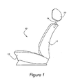
- a seat 10 has seat cushion 13 and seatback 12 mounted on a frame (not shown), incorporating a headrest adjustment mechanism which positions a headrest 20 upon a pair of mounting posts 14.
- a headrest adjustment mechanism which positions a headrest 20 upon a pair of mounting posts 14.
- One such post 14 is shown in Figure 1 .
- the two mounting posts 14 provide a foundation for the present headrest adjusting mechanism.
- Each of the posts 14 has a base portion, 14a and an eccentric portion, 14b.
- the base portions 14a extend within seatback 12.
- the lowermost portions of mounting posts 14 are attached to a height control bar 30.
- the attachment of posts 14a to height control bar 30 is facilitated by post bushings 40, which are fitted so as to accommodate movement in respective slots 38 which are provided within two portions of height control bar 30.
- the slots 38 allow lateral movement of mounting posts 14, so as to facilitate fore and aft movement of headrest 20.
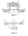
- mounting posts 14 The vertical positioning of mounting posts 14 is facilitated by an elevation motor 26, which drives lead screw 28 through nut 34, which is attached to height control bar 30.
- Motor 26 is attached to motor mounting bracket 24, which extends between sides 22 of the seat frame. As motor 26 turns in response to command from a controller, lead screw 28 will turn within nut 34, which will cause height control bar 30 to move either up or down, thereby moving mounting posts 14 and headrest 20 up or down as commanded.
- a system controller 90 ( Figure 4 ) reads the actual height of headrest 20 by means of height control sensor 42, which may, for example, be a multi-turn potentiometer geared to either motor 26 or to lead screw 28.
- height control sensor 42 may, for example, be a multi-turn potentiometer geared to either motor 26 or to lead screw 28.
- Those skilled in the art will appreciate in view of this disclosure that other types of position sensors, such as a linear potentiometer or a linear variable differential transformer may be used with a system according to the present invention.
- the measured height of headrest 20 is compared with the position of the passenger's head, which is detected by an occupant sensor 18.
- occupant sensor 18 is preferably of the capacitive type, the present system may utilize other types of sensors known to those skilled in the art and suggested by this disclosure.
- Mounting posts 14 extend generally vertically through post bearings 46 which are mounted at the upper portion of seat frame 22. As with the lowermost portions of mounting post 14, the middle portions of posts 14 extending through post bearings 46 may be displaced laterally in response to the fore and aft adjusting mechanism. This lateral movement is allowed by slots 72 formed in upper angle plate 64 and slots 76 formed in lower angle plate 68.
- Fore and aft motor 54 rotates a set of three bevel gears 52, so as to drive two lead screws 58 which are driven into nuts 50 housed within post bearings 46.
- mounting posts 14 When motor 54 rotates, mounting posts 14 will be moved either closer to each other or away from each other by the action of lead screws 58. In the event that mounting posts 14 are moved closer to each other, headrest 20 will be caused to move closer to the passenger's head. This results from the kinematics shown in Figure 3 , where it is seen that as base portions 14a move inwardly in slots 72 formed in upper angle plate 64, eccentric portions 14b are rotated forwardly because of their linkage within headrest 20.
- Controller 90 which is shown in Figure 4 , may be drawn either from a class of microprocessor controllers commonly employed to operate vehicular seating systems or from other types of controllers known to those skilled in the art and suggested by this disclosure. In any event, operation of controller 90 to adjust headrest 20 may be initiated either by manual switch 92 or by feedback provided by sensor 18.
- Sensor 18 may include a proximity sensor, such as a capacitive sensor mounted within headrest 20.
- Other sensors useful with the present invention may include sensors measuring vehicle parameters, such as transmission gear selection and occupant sensing.
- controller 90 will cause headrest 20 to be adjusted only if the seat 10 is occupied and if the vehicle is in a forward drive gear. If, on the other hand, the vehicle is in a reverse drive gear, or in park condition, headrest 20 may be placed in its lowermost and rearmost position, so as to promote the driver's ability to view the surrounding landscape through the back window of the vehicle.
- controller 90 operates a plurality of actuators 94, which include the actuators driven by elevation motor 26 and fore and aft motor 54.
- the controller is programmed to perform a method comprising several steps including activating a head proximity sensor located in the headrest and activating a first drive mechanism to adjust the vertical position of the headrest based upon a signal from the proximity sensor.
- the method may further include the step of activating a second drive mechanism to adjust the horizontal position of the headrest based upon the signal from the proximity sensor.
Landscapes
- Engineering & Computer Science (AREA)
- Aviation & Aerospace Engineering (AREA)
- Transportation (AREA)
- Mechanical Engineering (AREA)
- Seats For Vehicles (AREA)
- Chair Legs, Seat Parts, And Backrests (AREA)
Claims (9)
- Un système de retenue de tête pour un véhicule automobile, comprenant une pluralité de montants (14) s'étendant d'une manière généralement verticale à partir d'un dossier (12), un appui-tête (20) fixé sur les montants (14) et un mécanisme destiné à déplacer l'appui-tête (20) dans des directions longitudinales où chacun des montants (14) possède une partie de base inférieure (14a) avec un axe longitudinal et une partie excentrique supérieure (14b) sur laquelle est fixé l'appui-tête (20) et où un premier mécanisme d'entraînement (26, 28, 30) est couplé à la partie de base (14a) de chacun des montants (14) de façon à étendre et rétracter les montants (14) par rapport au dossier (12) de façon à rehausser et abaisser l'appui-tête et un deuxième mécanisme d'entraînement (50, 52, 54, 58) destiné à faire pivoter les montants (14) autour des axes longitudinaux de façon à déplacer l'appui-tête (20) dans les directions longitudinales,
caractérisé en ce que le deuxième mécanisme d'entraînement comprend un actionneur linéaire respectif (52, 54, 58) couplé à la partie de base (14a) de chacun des montants (14), les actionneurs linéaires (52, 54, 58) étant actionnables de façon à déplacer les parties de base (14a) des montants (14) latéralement dans des directions opposées. - Un système de retenue de tête selon la Revendication 1 où le premier mécanisme d'entraînement comprend une barre de réglage de la hauteur (30) avec les parties de base (14a) des montants (14) fixées sur celle-ci et un actionneur linéaire (26, 28) couplé à la barre de réglage de la hauteur (30) destiné à déplacer la barre de réglage de la hauteur (30) et les montants (14) verticalement.
- Un système de retenue de tête selon l'une quelconque des Revendications précédentes, où un mécanisme d'encliquetage (82, 86) est raccordé par entraînement entre les parties excentriques supérieures (14b) des montants (14).
- Un système de retenue de tête selon l'une quelconque des Revendications précédentes, comprenant en outre un système de commande (90) destiné à actionner le premier mécanisme d'entraînement (26, 28, 30) et le deuxième mécanisme d'entraînement (50, 52, 54, 58).
- Un système de retenue de tête selon la Revendication 4, où le système de commande (90) possède au moins un premier capteur (18) raccordé à celui-ci destiné à déterminer un état de fonctionnement d'un véhicule sur lequel le système de retenue de tête est installé et un deuxième capteur (18) destiné à déterminer la position d'une tête d'un passager par rapport à l'appui-tête (20).
- Un système de retenue de tête selon la Revendication 4 ou 5, où le système de commande (90) est actionnable de façon à déplacer l'appui-tête (20) vers sa position la plus basse et la plus reculée si un véhicule à l'intérieur duquel le système de retenue de tête est installé est déterminé se trouver dans une condition de sélection d'engrenage parmi les conditions de sélection point mort et marche arrière.
- Un siège (10) pour un véhicule automobile comprenant une armature de siège, un coussin de siège (13) monté sur l'armature de siège, un dossier (12) monté sur l'armature de siège et un appui-tête (20) caractérisé en ce que le siège (10) comprend en outre un système de retenue de tête selon l'une quelconque des Revendications 1 à 6 destiné à régler la position de l'appui-tête (20).
- Un siège selon la Revendication 7, où le siège comprend en outre un capteur (18) destiné à déterminer la position d'une tête d'un passager par rapport à l'appui-tête (20) et un système de commande (90) destiné à actionner le premier mécanisme d'entraînement (26, 28, 30) et le deuxième mécanisme d'entraînement (50, 52, 54, 58) de façon à régler la position de l'appui-tête (20) et d'établir une relation spatiale prédéterminée entre l'appui-tête (20) et la tête du passager.
- Un procédé de réglage d'un appui-tête de passager dans un véhicule automobile possédant un système de retenue de tête selon l'une quelconque des Revendications 1 à 6, le procédé comprenant les opérations suivantes :l'activation d'un capteur de proximité de tête (18) placé dans l'appui-tête (20),l'activation du premier mécanisme d'entraînement (26, 28, 30) de façon à régler la position verticale de l'appui-tête (20) en fonction d'un signal provenant du capteur de proximité (18), etl'activation de l'actionneur linéaire de façon à régler la position horizontale de l'appui-tête (20) en fonction du signal provenant du capteur de proximité.
Applications Claiming Priority (1)
| Application Number | Priority Date | Filing Date | Title |
|---|---|---|---|
| US11/278,083 US7232187B1 (en) | 2006-03-30 | 2006-03-30 | Head restraint for automotive vehicle |
Publications (3)
| Publication Number | Publication Date |
|---|---|
| EP1839940A2 EP1839940A2 (fr) | 2007-10-03 |
| EP1839940A3 EP1839940A3 (fr) | 2009-04-22 |
| EP1839940B1 true EP1839940B1 (fr) | 2012-07-25 |
Family
ID=38157023
Family Applications (1)
| Application Number | Title | Priority Date | Filing Date |
|---|---|---|---|
| EP07104258A Ceased EP1839940B1 (fr) | 2006-03-30 | 2007-03-15 | Appui-tête pour véhicule à moteur |
Country Status (3)
| Country | Link |
|---|---|
| US (1) | US7232187B1 (fr) |
| EP (1) | EP1839940B1 (fr) |
| CN (1) | CN101054070B (fr) |
Families Citing this family (46)
| Publication number | Priority date | Publication date | Assignee | Title |
|---|---|---|---|---|
| DE102005010594B4 (de) * | 2005-03-08 | 2010-09-16 | Brose Fahrzeugteile Gmbh & Co. Kommanditgesellschaft, Hallstadt | Lehne für einen Fahrzeugsitz |
| US7441821B2 (en) * | 2005-11-21 | 2008-10-28 | Lear Corporation | System and method for actuation of a head restraint |
| DE102006054166B4 (de) * | 2005-11-21 | 2009-07-30 | Lear Corp., Southfield | System und Verfahren zum Betätigen einer Kopfstütze |
| JP5087974B2 (ja) * | 2007-04-06 | 2012-12-05 | トヨタ紡織株式会社 | 車両用シート |
| CN101678784A (zh) * | 2007-04-24 | 2010-03-24 | 株式会社藤仓 | 头部保护装置位置调整装置和头部保护装置位置调整方法 |
| KR20100058604A (ko) * | 2007-08-28 | 2010-06-03 | 가부시키가이샤후지쿠라 | 헤드레스트 위치조정장치 및 헤드레스트 위치조정방법 |
| DE102007048151B3 (de) * | 2007-09-04 | 2009-01-22 | Lear Corporation, Southfield | Einstellbare Kopfstütze für einen Fahrzeugsitz |
| DE102007048152B3 (de) * | 2007-09-04 | 2009-01-22 | Lear Corporation, Southfield | Höheneinstellbare Kopfstütze für einen Fahrzeugsitz |
| US7871129B2 (en) * | 2007-12-05 | 2011-01-18 | Lear Corporation | Seat assembly having an adjustable head restraint assembly |
| WO2009073971A1 (fr) * | 2007-12-11 | 2009-06-18 | Magna Seating Inc. | Appui-tête escamotable motorisé |
| KR100992540B1 (ko) * | 2007-12-14 | 2010-11-08 | 현대자동차주식회사 | 차량용 폴딩 헤드레스트 장치 |
| US7758127B2 (en) * | 2008-01-23 | 2010-07-20 | Lear Corporation | Height adjustable head restraint for a vehicle seat |
| CN101524977B (zh) * | 2008-03-04 | 2013-09-04 | C.劳勃.汉默斯坦两合有限公司 | 用于机动车的高度可电动调整的头枕装置 |
| US8600624B2 (en) * | 2008-03-29 | 2013-12-03 | Lear Corporation | Method of matching component for vehicle head restraint actuation system |
| US8205941B2 (en) * | 2008-07-30 | 2012-06-26 | Trw Vehicle Safety Systems Inc. | Active head restraint for a vehicle seat |
| KR20100019390A (ko) * | 2008-08-07 | 2010-02-18 | 홍정명 | 자동차 시트의 헤드레스트 높이 조절 장치 |
| DE102008048313B3 (de) * | 2008-09-22 | 2010-03-04 | Lear Corp., Southfield | Einstellbare Fahrzeug-Kopfstützeneinrichtung für einen Fahrzeugsitz |
| DE102010003109B9 (de) * | 2009-04-22 | 2012-12-13 | Lear Corporation | Sitzanordnung mit beweglicher Kopfstütze |
| DE102009020117B4 (de) * | 2009-05-06 | 2013-11-14 | Lear Corp. | Sitzanordnung und verstellbare Kopfstützenanordnung |
| DE102010002525B9 (de) * | 2009-05-28 | 2012-12-13 | Lear Corp. | Sitzbaugruppe mit einer beweglichen Kopfstützen-Baugruppe |
| DE102009045833A1 (de) * | 2009-10-20 | 2011-05-26 | Lear Corp., Southfield | Sitzeinrichtung mit einer einstellbaren Kopfstützeneinrichtung |
| DE102009046660B4 (de) * | 2009-11-12 | 2011-11-10 | Lear Corporation | Sitzanordnung mit einer beweglichen Kopfstütze |
| DE102010001598B3 (de) * | 2010-02-04 | 2011-07-28 | Lear Corp., Mich. | Sitzbaugruppe mit einer beweglichen Kopfstützen-Baugruppe |
| US20110234411A1 (en) * | 2010-03-29 | 2011-09-29 | Harrington John T | Occupant Support System and Associated Method of Operation |
| US8657378B2 (en) | 2010-10-04 | 2014-02-25 | Lear Corporation | Seat assembly having an adjustable head restraint assembly |
| DE102010038250B4 (de) * | 2010-10-04 | 2015-05-28 | Grammer Automotive Cz S.R.O. | Kopfstütze mit Verstellung in Längsrichtung |
| DE102011005590B4 (de) | 2011-03-16 | 2013-05-16 | Lear Corporation | Sitzanordnung mit einer beweglichen Kopflehnenanordnung |
| DE102011006243B4 (de) * | 2011-03-28 | 2016-11-17 | Lear Corporation | Höhenverstellbare Kopfstütze für Fahrzeugsitze |
| FR2974043A1 (fr) * | 2011-04-14 | 2012-10-19 | Peugeot Citroen Automobiles Sa | Dossier de siege de vehicule a appui(s)-tete deplacable(s) transversalement en vue de l'augmentation du champ de retrovision |
| DE102012016567B4 (de) * | 2012-06-15 | 2014-02-20 | Johnson Controls Gmbh | Kopfstütze für einen Fahrzeugsitz |
| US8899685B2 (en) | 2012-06-27 | 2014-12-02 | Porter Group, Llc | Vehicle seat headrest assembly having vertical and longitudinal adjustment |
| EP2698277B1 (fr) * | 2012-08-13 | 2016-03-23 | Schukra Gerätebau GmbH | Système d'appuie-tête et procédé de réglage d'un appuie-tête |
| US9145078B2 (en) * | 2012-08-23 | 2015-09-29 | Lear Corporation | Vehicle seat head restraint actuation |
| MY179058A (en) * | 2013-02-28 | 2020-10-26 | Oro Agri Inc | Compositions and methods for the treatment of diseases on palms |
| JP6252760B2 (ja) * | 2014-02-18 | 2017-12-27 | アイシン精機株式会社 | ヘッドレスト装置 |
| US10106066B2 (en) * | 2014-02-20 | 2018-10-23 | Kpit Technologies Ltd. | Head restraint system |
| KR101553527B1 (ko) * | 2014-03-17 | 2015-09-17 | 현대다이모스(주) | 전동식 헤드레스트 |
| DE102014220556A1 (de) * | 2014-10-10 | 2016-04-14 | Volkswagen Aktiengesellschaft | Verfahren zum Betreiben eines Fahrzeugsitzes, Fahrzeugsitz und Fahrzeug |
| US10052248B1 (en) * | 2015-09-04 | 2018-08-21 | University Of South Florida | Wireless adjustable wheelchair headrest |
| US10899260B2 (en) * | 2015-10-05 | 2021-01-26 | Adient Luxembourg Holding S.Á R.L. | Headrest of a vehicle seat |
| US10160361B2 (en) * | 2016-07-27 | 2018-12-25 | Windsor Machine and Stamping (2009) Ltd. | Four-way electric power actuation head restraint |
| CN106274577B (zh) * | 2016-08-18 | 2018-10-09 | 江苏大学 | 一种机动车智能安全座椅及其控制方法 |
| US10384566B2 (en) * | 2017-08-25 | 2019-08-20 | Ford Global Technologies, Llc | Vehicle seat assembly |
| CN108312928A (zh) * | 2018-03-30 | 2018-07-24 | 北京汽车研究总院有限公司 | 一种座椅系统、车辆及调整头枕高度的方法 |
| DE102018008630A1 (de) | 2018-10-31 | 2020-04-30 | Daimler Ag | Vorrichtung zur Verringerung kinetosebedingter Störungen eines Insassen im Fahrbetrieb eines Fahrzeuges und Fahrzeug |
| JP7431674B2 (ja) * | 2020-06-10 | 2024-02-15 | 日本発條株式会社 | ヘッドレスト用スリーブ及びヘッドレスト |
Citations (3)
| Publication number | Priority date | Publication date | Assignee | Title |
|---|---|---|---|---|
| GB2057255A (en) * | 1979-07-18 | 1981-04-01 | Rentrop Hubbert & Wagner | Adjustable headrest arrangement |
| GB2301906A (en) * | 1995-06-07 | 1996-12-18 | Automotive Tech Int | Vehicle headrest and positioning system therefor |
| EP1369310A1 (fr) * | 2002-06-06 | 2003-12-10 | Honda Giken Kogyo Kabushiki Kaisha | Dispositif de protection de l'occupant d'un véhicule |
Family Cites Families (22)
| Publication number | Priority date | Publication date | Assignee | Title |
|---|---|---|---|---|
| US3311413A (en) * | 1964-07-17 | 1967-03-28 | Anderson Co | Headrest positioning mechanism |
| US5845000A (en) | 1992-05-05 | 1998-12-01 | Automotive Technologies International, Inc. | Optical identification and monitoring system using pattern recognition for use with vehicles |
| DE3427466A1 (de) | 1983-08-17 | 1985-03-07 | Brose Fahrzeugteile GmbH & Co KG, 8630 Coburg | Vorrichtung zur verstellung der hoehe einer kopfstuetze eines fahrzeugsitzes |
| JPS60158809A (ja) | 1984-01-31 | 1985-08-20 | 池田物産株式会社 | ヘツドレストの位置自動選定装置 |
| DE3440525A1 (de) * | 1984-11-06 | 1986-05-07 | Brose Fahrzeugteile GmbH & Co KG, 8630 Coburg | Vorrichtung zur bewegungssteuerung von kopfstuetzen innerhalb eines kraftfahrzeuges |
| JPH0613271B2 (ja) | 1987-12-26 | 1994-02-23 | 池田物産株式会社 | ヘッドレスト制御装置 |
| JP2646379B2 (ja) * | 1988-08-24 | 1997-08-27 | 株式会社タチエス | シフトチェンジ連動のヘッドレスト制御方法およびヘッドレスト制御装置 |
| US5080436A (en) * | 1990-04-06 | 1992-01-14 | Grammer Ag | Head support for a seat such as a vehicle seat |
| US5288129A (en) * | 1992-04-21 | 1994-02-22 | Tachi-S Co., Ltd. | Structure of a vertically movable powered headrest |
| US5835613A (en) | 1992-05-05 | 1998-11-10 | Automotive Technologies International, Inc. | Optical identification and monitoring system using pattern recognition for use with vehicles |
| US6088640A (en) | 1997-12-17 | 2000-07-11 | Automotive Technologies International, Inc. | Apparatus for determining the location of a head of an occupant in the presence of objects that obscure the head |
| EP0766913B1 (fr) | 1995-10-05 | 2001-01-03 | Atofina | Procédé de traitement des sols par fumigation |
| DE19624587A1 (de) * | 1996-06-20 | 1998-01-22 | Lear Corp | Sitz |
| US5848661A (en) | 1996-10-22 | 1998-12-15 | Lear Corporation | Vehicle seat assembly including at least one occupant sensing system and method of making same |
| DE19710836C2 (de) | 1997-03-15 | 1999-03-18 | Bosch Gmbh Robert | Verstellvorrichtung in einem Kraftfahrzeug |
| DE19756700C1 (de) | 1997-12-19 | 1998-12-17 | Daimler Benz Ag | Einstellbarer Fahrzeugsitz |
| KR20010034684A (ko) | 1999-01-27 | 2001-04-25 | 후루까와 준노스께 | 승객검출장치 |
| DE19916804C1 (de) * | 1999-04-14 | 2000-08-10 | Bayerische Motoren Werke Ag | Vorrichtung zum Justieren einer Fahrzeugkopfstütze sowie ein Verfahren unter Verwendung einer derartigen Vorrichtung |
| DE10012973B4 (de) | 2000-03-16 | 2004-02-26 | Daimlerchrysler Ag | Kopfstütze für einen Fahrzeugsitz |
| US6749257B2 (en) | 2000-10-30 | 2004-06-15 | Mueller Hermann-Frank | Head restraint for vehicles |
| JP4492439B2 (ja) * | 2004-06-16 | 2010-06-30 | トヨタ紡織株式会社 | ヘッドレスト |
| DE102005010594B4 (de) * | 2005-03-08 | 2010-09-16 | Brose Fahrzeugteile Gmbh & Co. Kommanditgesellschaft, Hallstadt | Lehne für einen Fahrzeugsitz |
-
2006
- 2006-03-30 US US11/278,083 patent/US7232187B1/en not_active Expired - Fee Related
-
2007
- 2007-03-15 EP EP07104258A patent/EP1839940B1/fr not_active Ceased
- 2007-03-22 CN CN2007100869341A patent/CN101054070B/zh not_active Expired - Fee Related
Patent Citations (3)
| Publication number | Priority date | Publication date | Assignee | Title |
|---|---|---|---|---|
| GB2057255A (en) * | 1979-07-18 | 1981-04-01 | Rentrop Hubbert & Wagner | Adjustable headrest arrangement |
| GB2301906A (en) * | 1995-06-07 | 1996-12-18 | Automotive Tech Int | Vehicle headrest and positioning system therefor |
| EP1369310A1 (fr) * | 2002-06-06 | 2003-12-10 | Honda Giken Kogyo Kabushiki Kaisha | Dispositif de protection de l'occupant d'un véhicule |
Also Published As
| Publication number | Publication date |
|---|---|
| CN101054070B (zh) | 2011-03-30 |
| EP1839940A3 (fr) | 2009-04-22 |
| EP1839940A2 (fr) | 2007-10-03 |
| CN101054070A (zh) | 2007-10-17 |
| US7232187B1 (en) | 2007-06-19 |
Similar Documents
| Publication | Publication Date | Title |
|---|---|---|
| EP1839940B1 (fr) | Appui-tête pour véhicule à moteur | |
| EP0761494B1 (fr) | Dispositif de commande de mémoires pour sièges véhicules à vitesses multiples | |
| EP2001703B1 (fr) | Dispositif de transmission pour un mécanisme de réglage de siège | |
| US20150375769A1 (en) | Adjustable Steering Column Controlled By A Human Machine Interface | |
| EP1077832B1 (fr) | Siege automobile reglable comportant un reglage de la hauteur et/ou de l'avance du siege et/ou de la hauteur du coussin de siege, et equipe d'un repose-tete pouvant etre deplace par un moteur electrique et guide au moyen d'un systeme de detection influence par la taille de l'utilisateur | |
| US8864172B2 (en) | Seatbelt buckle height adjustment mechanism | |
| US20120025582A1 (en) | Seat assembly having an adjustable head restraint assembly | |
| JPH0518200Y2 (fr) | ||
| EP1245438B1 (fr) | Structure de positionnement d'un organe de commande pour véhicule | |
| JPS6157218B2 (fr) | ||
| US8657379B2 (en) | Power return folding head restraint | |
| EP3613630B1 (fr) | Appuie-tête à commande de puissance électrique à quatre voies avec déploiement automatique | |
| EP3544852B1 (fr) | Siège pour véhicules à dossier segmenté et partie lombaire mobile | |
| EP1571064B1 (fr) | Ensemble de pédale et de colonne de direction réglable | |
| US6540299B1 (en) | Controlling headrest according to occupant size in a vehicle | |
| KR101326492B1 (ko) | 자동차용 전동식 시트 구동 장치 | |
| KR101441666B1 (ko) | 차량용 전동시트 높낮이 구동유니트 | |
| JP5288159B2 (ja) | アクチュエータ | |
| JP4413654B2 (ja) | 車両用インストルメントパネル | |
| JP2001137067A (ja) | 高さ自動調節ヘッドレスト付き座席 | |
| JP2023168135A (ja) | 車両用シート制御装置及び車両用シート | |
| EP3693213A1 (fr) | Appuie-tête inclinable à commande de puissance électrique et à déploiement automatique | |
| KR200146277Y1 (ko) | 시트등받이의 위치설정장치 | |
| KR19990027142A (ko) | 차량의 시트높이 조정장치 | |
| CN113120126A (zh) | 一种汽车后排乘员r点的验证装置及方法 |
Legal Events
| Date | Code | Title | Description |
|---|---|---|---|
| PUAI | Public reference made under article 153(3) epc to a published international application that has entered the european phase |
Free format text: ORIGINAL CODE: 0009012 |
|
| AK | Designated contracting states |
Kind code of ref document: A2 Designated state(s): AT BE BG CH CY CZ DE DK EE ES FI FR GB GR HU IE IS IT LI LT LU LV MC MT NL PL PT RO SE SI SK TR |
|
| AX | Request for extension of the european patent |
Extension state: AL BA HR MK YU |
|
| PUAL | Search report despatched |
Free format text: ORIGINAL CODE: 0009013 |
|
| AK | Designated contracting states |
Kind code of ref document: A3 Designated state(s): AT BE BG CH CY CZ DE DK EE ES FI FR GB GR HU IE IS IT LI LT LU LV MC MT NL PL PT RO SE SI SK TR |
|
| AX | Request for extension of the european patent |
Extension state: AL BA HR MK RS |
|
| AKX | Designation fees paid |
Designated state(s): DE GB SE |
|
| 17P | Request for examination filed |
Effective date: 20091203 |
|
| 17Q | First examination report despatched |
Effective date: 20100203 |
|
| GRAP | Despatch of communication of intention to grant a patent |
Free format text: ORIGINAL CODE: EPIDOSNIGR1 |
|
| GRAS | Grant fee paid |
Free format text: ORIGINAL CODE: EPIDOSNIGR3 |
|
| GRAA | (expected) grant |
Free format text: ORIGINAL CODE: 0009210 |
|
| AK | Designated contracting states |
Kind code of ref document: B1 Designated state(s): DE GB SE |
|
| REG | Reference to a national code |
Ref country code: GB Ref legal event code: FG4D |
|
| REG | Reference to a national code |
Ref country code: DE Ref legal event code: R096 Ref document number: 602007024138 Country of ref document: DE Effective date: 20120920 |
|
| REG | Reference to a national code |
Ref country code: SE Ref legal event code: TRGR |
|
| PLBE | No opposition filed within time limit |
Free format text: ORIGINAL CODE: 0009261 |
|
| STAA | Information on the status of an ep patent application or granted ep patent |
Free format text: STATUS: NO OPPOSITION FILED WITHIN TIME LIMIT |
|
| 26N | No opposition filed |
Effective date: 20130426 |
|
| REG | Reference to a national code |
Ref country code: DE Ref legal event code: R097 Ref document number: 602007024138 Country of ref document: DE Effective date: 20130426 |
|
| PGFP | Annual fee paid to national office [announced via postgrant information from national office to epo] |
Ref country code: SE Payment date: 20170307 Year of fee payment: 11 |
|
| PGFP | Annual fee paid to national office [announced via postgrant information from national office to epo] |
Ref country code: GB Payment date: 20170223 Year of fee payment: 11 |
|
| PGFP | Annual fee paid to national office [announced via postgrant information from national office to epo] |
Ref country code: DE Payment date: 20170331 Year of fee payment: 11 |
|
| REG | Reference to a national code |
Ref country code: DE Ref legal event code: R079 Ref document number: 602007024138 Country of ref document: DE Free format text: PREVIOUS MAIN CLASS: B60N0002480000 Ipc: B60N0002800000 |
|
| REG | Reference to a national code |
Ref country code: DE Ref legal event code: R119 Ref document number: 602007024138 Country of ref document: DE |
|
| PG25 | Lapsed in a contracting state [announced via postgrant information from national office to epo] |
Ref country code: SE Free format text: LAPSE BECAUSE OF NON-PAYMENT OF DUE FEES Effective date: 20180316 |
|
| GBPC | Gb: european patent ceased through non-payment of renewal fee |
Effective date: 20180315 |
|
| PG25 | Lapsed in a contracting state [announced via postgrant information from national office to epo] |
Ref country code: DE Free format text: LAPSE BECAUSE OF NON-PAYMENT OF DUE FEES Effective date: 20181002 |
|
| PG25 | Lapsed in a contracting state [announced via postgrant information from national office to epo] |
Ref country code: GB Free format text: LAPSE BECAUSE OF NON-PAYMENT OF DUE FEES Effective date: 20180315 |