EP1839940B1 - A head restraint for a motor vehicle - Google Patents
A head restraint for a motor vehicle Download PDFInfo
- Publication number
- EP1839940B1 EP1839940B1 EP07104258A EP07104258A EP1839940B1 EP 1839940 B1 EP1839940 B1 EP 1839940B1 EP 07104258 A EP07104258 A EP 07104258A EP 07104258 A EP07104258 A EP 07104258A EP 1839940 B1 EP1839940 B1 EP 1839940B1
- Authority
- EP
- European Patent Office
- Prior art keywords
- head
- mounting posts
- head rest
- restraint system
- drive mechanism
- Prior art date
- Legal status (The legal status is an assumption and is not a legal conclusion. Google has not performed a legal analysis and makes no representation as to the accuracy of the status listed.)
- Expired - Fee Related
Links
- 230000003213 activating effect Effects 0.000 claims description 6
- 238000000034 method Methods 0.000 claims description 5
- 230000005540 biological transmission Effects 0.000 description 1
- 238000010586 diagram Methods 0.000 description 1
- 238000004519 manufacturing process Methods 0.000 description 1
Images

Classifications
-
- B—PERFORMING OPERATIONS; TRANSPORTING
- B60—VEHICLES IN GENERAL
- B60N—SEATS SPECIALLY ADAPTED FOR VEHICLES; VEHICLE PASSENGER ACCOMMODATION NOT OTHERWISE PROVIDED FOR
- B60N2/00—Seats specially adapted for vehicles; Arrangement or mounting of seats in vehicles
- B60N2/02—Seats specially adapted for vehicles; Arrangement or mounting of seats in vehicles the seat or part thereof being movable, e.g. adjustable
- B60N2/0224—Non-manual adjustments, e.g. with electrical operation
- B60N2/02246—Electric motors therefor
-
- B—PERFORMING OPERATIONS; TRANSPORTING
- B60—VEHICLES IN GENERAL
- B60N—SEATS SPECIALLY ADAPTED FOR VEHICLES; VEHICLE PASSENGER ACCOMMODATION NOT OTHERWISE PROVIDED FOR
- B60N2/00—Seats specially adapted for vehicles; Arrangement or mounting of seats in vehicles
- B60N2/80—Head-rests
- B60N2/806—Head-rests movable or adjustable
- B60N2/809—Head-rests movable or adjustable vertically slidable
- B60N2/829—Head-rests movable or adjustable vertically slidable characterised by their adjusting mechanisms, e.g. electric motors
-
- B—PERFORMING OPERATIONS; TRANSPORTING
- B60—VEHICLES IN GENERAL
- B60N—SEATS SPECIALLY ADAPTED FOR VEHICLES; VEHICLE PASSENGER ACCOMMODATION NOT OTHERWISE PROVIDED FOR
- B60N2/00—Seats specially adapted for vehicles; Arrangement or mounting of seats in vehicles
- B60N2/80—Head-rests
- B60N2/806—Head-rests movable or adjustable
- B60N2/865—Head-rests movable or adjustable providing a fore-and-aft movement with respect to the occupant's head
Landscapes
- Engineering & Computer Science (AREA)
- Aviation & Aerospace Engineering (AREA)
- Transportation (AREA)
- Mechanical Engineering (AREA)
- Seats For Vehicles (AREA)
- Chair Legs, Seat Parts, And Backrests (AREA)
Description
- The present invention relates to a head restraint system for a motor vehicle including a headrest with motor driven adjustments for both the height and the horizontal position of the headrest.
- Adjustable headrests have been used for many years in automotive vehicles. For optimum effectiveness, such headrests must be adjusted properly. Because achieving a correct adjustment is more difficult in the case of manually adjustable headrests, motor drive headrests have been offered.
-
U.S. patent 6,511,130 discloses a head restraint assembly comprising a plurality of mounting posts extending generally vertically from a seatback, a head rest carried upon the mounting posts and a mechanism to move the head restraint in a fore and aft directions. The head restraint is adjustable both manually and by means of a motor. The design of this head restraint assembly is, complex, expensive to manufacture and heavy. -
U.S. Patent 5,080,436 discloses a head restraint system for a motor vehicle which is considered the closest prior art for claims 1 and 9. - It is an object of the present invention to provide a head restraint system for a motor vehicle that is relatively compact, of low weight and low complexity so as to be economical to produce.
- According to a first aspect of the invention there is provided a head restraint system for an automotive vehicle, as set forth in claim 1 of the appended claims.
- The first drive mechanism may comprise a height control bar having the base portions of the mounting posts mounted thereto and a linear actuator coupled to the height control bar, for moving the height control bar and the mounting posts vertically.
- The linear actuator may comprise a lead screw powered by an electric motor.
- Each of the linear actuators may comprise a lead screw powered by a common electric motor.
- An indexing mechanism may be driveably connected between the upper eccentric portions of the mounting posts.
- The indexing mechanism may comprise a gear train having a respective primary gears locked rotationally to each upper eccentric portion and a plurality of secondary gears in meshed engagement between the primary gears.
- The head restraint system may further comprise a controller for operating the first drive mechanism and the second drive mechanism.
- The controller may comprise a manual controller.
- The controller may have at least a first sensor connected thereto for determining an operating state of a vehicle to which the head restraint system is fitted and a second sensor for determining the position of a head of a passenger with respect to the head rest.
- The second sensor comprises a capacitive sensor.
- The second sensor may comprise a capacitive sensor housed within the head rest.
- The controller may be operable to move the head rest to its lowest and rearmost position if a vehicle within which the head restraint system is installed is determined to be in one of a park and a reverse gear selection condition.
- According to a second aspect of the invention there is provided a seat for an automotive vehicle as set forth in claim 7 of the appended claims.
- The seat may further comprise a sensor for determining the position of a head of a passenger with respect to the head rest and a controller for operating the first drive mechanism and the second drive mechanism so as to adjust the position of the head rest to establish a predetermined spatial relationship between the head rest and the head of the passenger.
- According to a third aspect of the invention there is provided a method of adjusting a passenger head rest in an automotive vehicle having a head restraint system constructed in accordance with said first aspect of the invention, as set forth in claim 9 of the appended claims.
- The first drive mechanism may telescopically extend the plurality of headrest mounting posts in a generally vertical direction and the second drive mechanism may cause the mounting posts to rotate such that the eccentric upper portions of the head rest mounting posts reposition the headrest in a horizontal direction.
- It is an advantage of a system according to the present invention that a passenger headrest in a vehicle may be adjusted either manually or automatically with precision, so as to achieve a desired position offering enhanced protection for a vehicle occupant.
- It is a further advantage of the present invention that the present headrest adjusting system provides enhanced functionality with minimum cost and weight.
- It is a further advantage of a system according to the present invention that the present headrest adjusting system may be fully contained within a seat of a vehicle, without the need for external electronic logic support.
- The invention will now be described by way of example with reference to the accompanying drawing of which:-
-
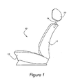
Figure 1 is a schematic representation of an automotive seat according to the present invention; -
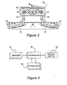
Figure 2 is a perspective view of a headrest adjusting mechanism according to the present invention; -
Figure 3 is a plan view of the top or upper portion of the present headrest adjusting system, taken in the direction of line 3-3 ofFigure 2 ; and -
Figure 4 is a block diagram of a control system suitable for use with a headrest adjusting system according to the present invention. - As shown in
Figure 1 , aseat 10 hasseat cushion 13 andseatback 12 mounted on a frame (not shown), incorporating a headrest adjustment mechanism which positions aheadrest 20 upon a pair ofmounting posts 14. Onesuch post 14 is shown inFigure 1 . - As shown in
Figure 2 , the twomounting posts 14 provide a foundation for the present headrest adjusting mechanism. Each of theposts 14 has a base portion, 14a and an eccentric portion, 14b. Thebase portions 14a extend withinseatback 12. The lowermost portions ofmounting posts 14 are attached to aheight control bar 30. The attachment ofposts 14a toheight control bar 30 is facilitated bypost bushings 40, which are fitted so as to accommodate movement inrespective slots 38 which are provided within two portions ofheight control bar 30. As explained more fully below, theslots 38 allow lateral movement ofmounting posts 14, so as to facilitate fore and aft movement ofheadrest 20. - The vertical positioning of
mounting posts 14 is facilitated by anelevation motor 26, which driveslead screw 28 throughnut 34, which is attached toheight control bar 30.Motor 26 is attached tomotor mounting bracket 24, which extends betweensides 22 of the seat frame. Asmotor 26 turns in response to command from a controller,lead screw 28 will turn withinnut 34, which will causeheight control bar 30 to move either up or down, thereby moving mountingposts 14 andheadrest 20 up or down as commanded. - A system controller 90 (
Figure 4 ) reads the actual height ofheadrest 20 by means ofheight control sensor 42, which may, for example, be a multi-turn potentiometer geared to eithermotor 26 or to leadscrew 28. Those skilled in the art will appreciate in view of this disclosure that other types of position sensors, such as a linear potentiometer or a linear variable differential transformer may be used with a system according to the present invention. The measured height ofheadrest 20 is compared with the position of the passenger's head, which is detected by anoccupant sensor 18. Althoughoccupant sensor 18 is preferably of the capacitive type, the present system may utilize other types of sensors known to those skilled in the art and suggested by this disclosure. -
Mounting posts 14 extend generally vertically throughpost bearings 46 which are mounted at the upper portion ofseat frame 22. As with the lowermost portions ofmounting post 14, the middle portions ofposts 14 extending throughpost bearings 46 may be displaced laterally in response to the fore and aft adjusting mechanism. This lateral movement is allowed byslots 72 formed inupper angle plate 64 andslots 76 formed inlower angle plate 68. Fore andaft motor 54 rotates a set of threebevel gears 52, so as to drive twolead screws 58 which are driven intonuts 50 housed withinpost bearings 46. - When
motor 54 rotates, mountingposts 14 will be moved either closer to each other or away from each other by the action oflead screws 58. In the event that mountingposts 14 are moved closer to each other,headrest 20 will be caused to move closer to the passenger's head. This results from the kinematics shown inFigure 3 , where it is seen that asbase portions 14a move inwardly inslots 72 formed inupper angle plate 64,eccentric portions 14b are rotated forwardly because of their linkage withinheadrest 20. - During rotation of the
mounting posts 14,primary gears 82, which are rotationally locked toeccentric portions 14b ofposts 14, will rotate witheccentric portions 14b, andsecondary gears 86, which are imposed betweenprimary gears 82, will assure that rotation of each of themounting posts 14 is equal. This indexing mechanism will maintain the desired parallel relationship between the seatback andheadrest 20. -
Controller 90, which is shown inFigure 4 , may be drawn either from a class of microprocessor controllers commonly employed to operate vehicular seating systems or from other types of controllers known to those skilled in the art and suggested by this disclosure. In any event, operation ofcontroller 90 to adjustheadrest 20 may be initiated either bymanual switch 92 or by feedback provided bysensor 18.Sensor 18 may include a proximity sensor, such as a capacitive sensor mounted withinheadrest 20. Other sensors useful with the present invention may include sensors measuring vehicle parameters, such as transmission gear selection and occupant sensing. - In general,
controller 90 will causeheadrest 20 to be adjusted only if theseat 10 is occupied and if the vehicle is in a forward drive gear. If, on the other hand, the vehicle is in a reverse drive gear, or in park condition,headrest 20 may be placed in its lowermost and rearmost position, so as to promote the driver's ability to view the surrounding landscape through the back window of the vehicle. - As further shown in
Figure 4 ,controller 90 operates a plurality ofactuators 94, which include the actuators driven byelevation motor 26 and fore andaft motor 54. - The controller is programmed to perform a method comprising several steps including activating a head proximity sensor located in the headrest and activating a first drive mechanism to adjust the vertical position of the headrest based upon a signal from the proximity sensor. The method may further include the step of activating a second drive mechanism to adjust the horizontal position of the headrest based upon the signal from the proximity sensor.
Claims (9)
- A head restraint system for an automotive vehicle, comprising a plurality of mounting posts (14) extending generally vertically from a seatback (12), a head rest (20) carried upon the mounting posts (14) and a mechanism to move the head rest (20) in fore and aft directions wherein each of the mounting posts (14) has a lower base portion (14a) with a longitudinal axis and an upper eccentric portion (14b) upon which is carried the head rest (20) and that a first drive mechanism (26, 28, 30) is coupled to the base portion (14a) of each of the mounting posts (14) for extending and retracting the mounting posts (14) relative to the seatback (12) so as to raise and lower the head rest and a second drive mechanism (50, 52, 54, 58) for rotating the mounting posts (14) about the longitudinal axes so as to move the head rest (20) in the fore and aft directions
characterised in that the second drive mechanism comprises a respective linear actuator (52, 54, 58) coupled to the base portion (14a) of each of the mounting posts (14), the linear actuators (52, 54, 58) being operable to move the base portions (14a) of the mounting posts (14) laterally in opposite directions. - A head restraint system as claimed in Claim 1
wherein the first drive mechanism comprises a height control bar (30) having the base portions (14a) of the mounting posts (14) mounted thereto and a linear actuator (26, 28) coupled to the height control bar (30) for moving the height control bar (30) and the mounting posts (14) vertically. - A head restraint system as claimed in any preceding claim, wherein an indexing mechanism (82, 86) is driveably connected between the upper eccentric portions (14b) of the mounting posts (14).
- A head restraint system as claimed in any preceding claim, further comprising a controller (90) for operating the first drive mechanism (26, 28, 30) and the second drive mechanism (50, 52, 54, 58).
- A head restraint system as claimed in claim 4,
wherein the controller (90) has at least a first sensor (18) connected thereto for determining an operating state of a vehicle to which the head restraint system is fitted and a second sensor (18) for determining the position of a head of a passenger with respect to the head rest (20). - A head restraint system as claimed in claim 4 or 5, wherein the controller (90) is operable to move the head rest (20) to its lowest and rearmost position if a vehicle within which the head restraint system is installed is determined to be in one of a park and a reverse gear selection condition.
- A seat (10) for an automotive vehicle comprising a seat frame, a seat cushion (13) mounted to the seat frame, a seatback (12) mounted to the seat frame and a head rest (20) characterised in that the seat (10) further comprises a head restraint system as claimed in any of claims 1 to 6 to adjust the position of the head rest (20).
- A seat as claimed in claim 7, wherein the seat further comprises a sensor (18) for determining the position of a head of a passenger with respect to the head rest (20) and a controller (90) for operating the first drive mechanism (26, 28, 30) and the second drive mechanism (50, 52, 54, 58) so as to adjust the position of the head rest (20) to establish a predetermined spatial relationship between the head rest (20) and the head of the passenger.
- A method of adjusting a passenger head rest in an automotive vehicle having a head restraint system as claimed in any of claims 1 to 6, the method comprising the steps of
activating a head proximity sensor (18) located in the head rest (20),
activating the first drive mechanism (26, 28, 30) to adjust the vertical position of the head rest (20) based upon a signal from the proximity sensor (18) and
activating the linear actuators to adjust the horizontal position of the head rest (20) based upon the signal from the proximity sensor.
Applications Claiming Priority (1)
| Application Number | Priority Date | Filing Date | Title |
|---|---|---|---|
| US11/278,083 US7232187B1 (en) | 2006-03-30 | 2006-03-30 | Head restraint for automotive vehicle |
Publications (3)
| Publication Number | Publication Date |
|---|---|
| EP1839940A2 EP1839940A2 (en) | 2007-10-03 |
| EP1839940A3 EP1839940A3 (en) | 2009-04-22 |
| EP1839940B1 true EP1839940B1 (en) | 2012-07-25 |
Family
ID=38157023
Family Applications (1)
| Application Number | Title | Priority Date | Filing Date |
|---|---|---|---|
| EP07104258A Expired - Fee Related EP1839940B1 (en) | 2006-03-30 | 2007-03-15 | A head restraint for a motor vehicle |
Country Status (3)
| Country | Link |
|---|---|
| US (1) | US7232187B1 (en) |
| EP (1) | EP1839940B1 (en) |
| CN (1) | CN101054070B (en) |
Families Citing this family (46)
| Publication number | Priority date | Publication date | Assignee | Title |
|---|---|---|---|---|
| DE102005010594B4 (en) * | 2005-03-08 | 2010-09-16 | Brose Fahrzeugteile Gmbh & Co. Kommanditgesellschaft, Hallstadt | Lean for a vehicle seat |
| DE102006054166B4 (en) * | 2005-11-21 | 2009-07-30 | Lear Corp., Southfield | System and method for operating a headrest |
| US7441821B2 (en) * | 2005-11-21 | 2008-10-28 | Lear Corporation | System and method for actuation of a head restraint |
| JP5087974B2 (en) * | 2007-04-06 | 2012-12-05 | トヨタ紡織株式会社 | Vehicle seat |
| CN102887088B (en) * | 2007-04-24 | 2016-06-08 | 株式会社藤仓 | Head rest position adjusting device and head restraint location regulation method |
| JP5005767B2 (en) * | 2007-08-28 | 2012-08-22 | 株式会社フジクラ | Headrest position adjustment device and headrest position adjustment method |
| DE102007048151B3 (en) * | 2007-09-04 | 2009-01-22 | Lear Corporation, Southfield | Seat e.g. front seat, for e.g. car, has locking mechanism with spindle having eccentric drive that works together with one ratchet such that release device rotates spindle and moves ratchet from connection with other ratchet |
| DE102007048152B3 (en) * | 2007-09-04 | 2009-01-22 | Lear Corporation, Southfield | Vehicle e.g. car, seat, has locking mechanism with shaft element comprising protrusion that is disengaged in disengaged rotation position of shaft by series of recesses, such that headrest and frame are slided along rod |
| US7871129B2 (en) * | 2007-12-05 | 2011-01-18 | Lear Corporation | Seat assembly having an adjustable head restraint assembly |
| WO2009073971A1 (en) * | 2007-12-11 | 2009-06-18 | Magna Seating Inc. | Powered retracting head restraint |
| KR100992540B1 (en) * | 2007-12-14 | 2010-11-08 | 현대자동차주식회사 | Apparatus for folding headrest in vehicles |
| US7758127B2 (en) * | 2008-01-23 | 2010-07-20 | Lear Corporation | Height adjustable head restraint for a vehicle seat |
| CN101524977B (en) * | 2008-03-04 | 2013-09-04 | C.劳勃.汉默斯坦两合有限公司 | An electrically height-adjustable head rest device of a motor vehicle |
| US8600624B2 (en) * | 2008-03-29 | 2013-12-03 | Lear Corporation | Method of matching component for vehicle head restraint actuation system |
| US8205941B2 (en) * | 2008-07-30 | 2012-06-26 | Trw Vehicle Safety Systems Inc. | Active head restraint for a vehicle seat |
| KR20100019390A (en) * | 2008-08-07 | 2010-02-18 | 홍정명 | A power headrest for a vehicle's seat |
| DE102008048313B3 (en) * | 2008-09-22 | 2010-03-04 | Lear Corp., Southfield | Adjustable vehicle headrest device for a vehicle seat |
| DE102010003109B9 (en) * | 2009-04-22 | 2012-12-13 | Lear Corporation | Seat arrangement with movable headrest |
| DE102009020117B4 (en) * | 2009-05-06 | 2013-11-14 | Lear Corp. | Seat assembly and adjustable head restraint assembly |
| DE102010002525B9 (en) * | 2009-05-28 | 2012-12-13 | Lear Corp. | Seat assembly with a movable headrest assembly |
| DE102009045833A1 (en) * | 2009-10-20 | 2011-05-26 | Lear Corp., Southfield | Seat device with an adjustable headrest device |
| DE102009046660B4 (en) * | 2009-11-12 | 2011-11-10 | Lear Corporation | Seat arrangement with a movable headrest |
| DE102010001598B3 (en) * | 2010-02-04 | 2011-07-28 | Lear Corp., Mich. | Seat assembly with a movable headrest assembly |
| US20110234411A1 (en) * | 2010-03-29 | 2011-09-29 | Harrington John T | Occupant Support System and Associated Method of Operation |
| US8657378B2 (en) | 2010-10-04 | 2014-02-25 | Lear Corporation | Seat assembly having an adjustable head restraint assembly |
| DE102010038250B4 (en) * | 2010-10-04 | 2015-05-28 | Grammer Automotive Cz S.R.O. | Headrest with longitudinal adjustment |
| DE102011005590B4 (en) | 2011-03-16 | 2013-05-16 | Lear Corporation | Seat assembly with a movable headrest assembly |
| DE102011006243B4 (en) * | 2011-03-28 | 2016-11-17 | Lear Corporation | Height-adjustable headrest for vehicle seats |
| FR2974043A1 (en) * | 2011-04-14 | 2012-10-19 | Peugeot Citroen Automobiles Sa | Backrest for e.g. bench seat of car, has lower frame portion slidably mounted in sliding element so as to be transversely moved between securing position and lateral storage position in which cushion is shifted to lateral side of car |
| DE102012016567B4 (en) * | 2012-06-15 | 2014-02-20 | Johnson Controls Gmbh | Headrest for a vehicle seat |
| EP2867061A4 (en) | 2012-06-27 | 2016-04-06 | Porter Group Llc | Vehicle seat headrest assembly having vertical and longitudinal adjustment |
| EP2698277B1 (en) | 2012-08-13 | 2016-03-23 | Schukra Gerätebau GmbH | Headrest system and method of adjusting a headrest |
| US9145078B2 (en) * | 2012-08-23 | 2015-09-29 | Lear Corporation | Vehicle seat head restraint actuation |
| MY179058A (en) * | 2013-02-28 | 2020-10-26 | Oro Agri Inc | Compositions and methods for the treatment of diseases on palms |
| JP6252760B2 (en) * | 2014-02-18 | 2017-12-27 | アイシン精機株式会社 | Headrest device |
| CN105980202A (en) * | 2014-02-20 | 2016-09-28 | Kpit技术有限责任公司 | Head restraint system for vehicles |
| KR101553527B1 (en) * | 2014-03-17 | 2015-09-17 | 현대다이모스(주) | Automatic headrest |
| DE102014220556A1 (en) * | 2014-10-10 | 2016-04-14 | Volkswagen Aktiengesellschaft | Method for operating a vehicle seat, vehicle seat and vehicle |
| US10052248B1 (en) * | 2015-09-04 | 2018-08-21 | University Of South Florida | Wireless adjustable wheelchair headrest |
| JP2018534198A (en) * | 2015-10-05 | 2018-11-22 | アディエント ルクセンブルク ホールディング エス.エー アール.エル. | Vehicle seat headrest |
| US10160361B2 (en) * | 2016-07-27 | 2018-12-25 | Windsor Machine and Stamping (2009) Ltd. | Four-way electric power actuation head restraint |
| CN106274577B (en) * | 2016-08-18 | 2018-10-09 | 江苏大学 | A kind of motor vehicle intelligent safety seat and its control method |
| US10384566B2 (en) * | 2017-08-25 | 2019-08-20 | Ford Global Technologies, Llc | Vehicle seat assembly |
| CN108312928A (en) * | 2018-03-30 | 2018-07-24 | 北京汽车研究总院有限公司 | A kind of seat system, vehicle and the method for adjusting height of headrest |
| DE102018008630A1 (en) * | 2018-10-31 | 2020-04-30 | Daimler Ag | Device for reducing kinetic disorders of an occupant while driving a vehicle and vehicle |
| JP7431674B2 (en) * | 2020-06-10 | 2024-02-15 | 日本発條株式会社 | Headrest sleeves and headrests |
Citations (3)
| Publication number | Priority date | Publication date | Assignee | Title |
|---|---|---|---|---|
| GB2057255A (en) * | 1979-07-18 | 1981-04-01 | Rentrop Hubbert & Wagner | Adjustable headrest arrangement |
| GB2301906A (en) * | 1995-06-07 | 1996-12-18 | Automotive Tech Int | Vehicle headrest and positioning system therefor |
| EP1369310A1 (en) * | 2002-06-06 | 2003-12-10 | Honda Giken Kogyo Kabushiki Kaisha | Vehicle occupant protection apparatus |
Family Cites Families (22)
| Publication number | Priority date | Publication date | Assignee | Title |
|---|---|---|---|---|
| US3311413A (en) * | 1964-07-17 | 1967-03-28 | Anderson Co | Headrest positioning mechanism |
| US5845000A (en) | 1992-05-05 | 1998-12-01 | Automotive Technologies International, Inc. | Optical identification and monitoring system using pattern recognition for use with vehicles |
| DE3427466A1 (en) | 1983-08-17 | 1985-03-07 | Brose Fahrzeugteile GmbH & Co KG, 8630 Coburg | DEVICE FOR ADJUSTING THE HEIGHT OF A HEADREST OF A VEHICLE SEAT |
| JPS60158809A (en) | 1984-01-31 | 1985-08-20 | 池田物産株式会社 | Automatic selector of headrest position |
| DE3440525A1 (en) * | 1984-11-06 | 1986-05-07 | Brose Fahrzeugteile GmbH & Co KG, 8630 Coburg | Device for controlling the movement of headrests within a motor vehicle |
| JPH0613271B2 (en) | 1987-12-26 | 1994-02-23 | 池田物産株式会社 | Headrest control device |
| JP2646379B2 (en) * | 1988-08-24 | 1997-08-27 | 株式会社タチエス | Headrest control method and headrest control device linked to shift change |
| US5080436A (en) * | 1990-04-06 | 1992-01-14 | Grammer Ag | Head support for a seat such as a vehicle seat |
| US5288129A (en) * | 1992-04-21 | 1994-02-22 | Tachi-S Co., Ltd. | Structure of a vertically movable powered headrest |
| US6088640A (en) | 1997-12-17 | 2000-07-11 | Automotive Technologies International, Inc. | Apparatus for determining the location of a head of an occupant in the presence of objects that obscure the head |
| US5835613A (en) | 1992-05-05 | 1998-11-10 | Automotive Technologies International, Inc. | Optical identification and monitoring system using pattern recognition for use with vehicles |
| EP0766913B1 (en) | 1995-10-05 | 2001-01-03 | Atofina | Method for treating soils by fumigation |
| DE19624587A1 (en) * | 1996-06-20 | 1998-01-22 | Lear Corp | Seat |
| US5848661A (en) | 1996-10-22 | 1998-12-15 | Lear Corporation | Vehicle seat assembly including at least one occupant sensing system and method of making same |
| DE19710836C2 (en) | 1997-03-15 | 1999-03-18 | Bosch Gmbh Robert | Adjustment device in a motor vehicle |
| DE19756700C1 (en) | 1997-12-19 | 1998-12-17 | Daimler Benz Ag | Adjustable vehicle seat |
| KR20010034684A (en) | 1999-01-27 | 2001-04-25 | 후루까와 준노스께 | Occupant detecting device |
| DE19916804C1 (en) * | 1999-04-14 | 2000-08-10 | Bayerische Motoren Werke Ag | Headrest adjustment device for vehicle passenger seat uses sensor incorporated in headrest using 2 capacitor plates positioned so that head of passenger acts as capacitor dielectric |
| DE10012973B4 (en) | 2000-03-16 | 2004-02-26 | Daimlerchrysler Ag | Headrest for a vehicle seat |
| US6749257B2 (en) | 2000-10-30 | 2004-06-15 | Mueller Hermann-Frank | Head restraint for vehicles |
| JP4492439B2 (en) * | 2004-06-16 | 2010-06-30 | トヨタ紡織株式会社 | Headrest |
| DE102005010594B4 (en) * | 2005-03-08 | 2010-09-16 | Brose Fahrzeugteile Gmbh & Co. Kommanditgesellschaft, Hallstadt | Lean for a vehicle seat |
-
2006
- 2006-03-30 US US11/278,083 patent/US7232187B1/en not_active Expired - Fee Related
-
2007
- 2007-03-15 EP EP07104258A patent/EP1839940B1/en not_active Expired - Fee Related
- 2007-03-22 CN CN2007100869341A patent/CN101054070B/en not_active Expired - Fee Related
Patent Citations (3)
| Publication number | Priority date | Publication date | Assignee | Title |
|---|---|---|---|---|
| GB2057255A (en) * | 1979-07-18 | 1981-04-01 | Rentrop Hubbert & Wagner | Adjustable headrest arrangement |
| GB2301906A (en) * | 1995-06-07 | 1996-12-18 | Automotive Tech Int | Vehicle headrest and positioning system therefor |
| EP1369310A1 (en) * | 2002-06-06 | 2003-12-10 | Honda Giken Kogyo Kabushiki Kaisha | Vehicle occupant protection apparatus |
Also Published As
| Publication number | Publication date |
|---|---|
| EP1839940A2 (en) | 2007-10-03 |
| US7232187B1 (en) | 2007-06-19 |
| EP1839940A3 (en) | 2009-04-22 |
| CN101054070A (en) | 2007-10-17 |
| CN101054070B (en) | 2011-03-30 |
Similar Documents
| Publication | Publication Date | Title |
|---|---|---|
| EP1839940B1 (en) | A head restraint for a motor vehicle | |
| EP0761494B1 (en) | Multiple speed vehicle seat memory control apparatus | |
| EP2001703B1 (en) | Transmission device for seat adjuster | |
| US20150375769A1 (en) | Adjustable Steering Column Controlled By A Human Machine Interface | |
| EP1077832B1 (en) | Adjustable vehicle seat with horizontal seat adjustment and/or seat height adjustment and/or seat depth adjustment and neck-rest that can be displaced by an electric motor and guided by a sensor system influenced by the size of the user | |
| US9365140B2 (en) | Headrest system and method of adjusting a headrest | |
| JPH0518200Y2 (en) | ||
| US20120025582A1 (en) | Seat assembly having an adjustable head restraint assembly | |
| US20140132056A1 (en) | Seatbelt buckle height adjustment mechanism | |
| EP1245438B1 (en) | Controller positioning structure for vehicle | |
| JPS6157218B2 (en) | ||
| EP3613630B1 (en) | Four-way electric power actuation head restraint with automated deployment | |
| JP2009255778A (en) | Arm rest device | |
| US6540299B1 (en) | Controlling headrest according to occupant size in a vehicle | |
| EP1571064B1 (en) | Adjustable pedal and steering mechanism | |
| WO2020178379A1 (en) | Side airbag arrangement in a vehicle seat | |
| EP3544852B1 (en) | Seat for vehicles with segmented backrest and movable lumbar portion | |
| KR101326492B1 (en) | Driving apparatus for electromotive seat | |
| JP5288159B2 (en) | Actuator | |
| KR101441666B1 (en) | Control-unit for the seat height | |
| JP4413654B2 (en) | Instrument panel for vehicle | |
| KR102309253B1 (en) | Seat cushion extension apparatus using double gear and seat cushion comprising the same | |
| JP2023168135A (en) | Vehicle seat control device and vehicle seat | |
| EP3693213A1 (en) | Electric power actuation tilting head restraint with automated deployment | |
| JPH0513631Y2 (en) |
Legal Events
| Date | Code | Title | Description |
|---|---|---|---|
| PUAI | Public reference made under article 153(3) epc to a published international application that has entered the european phase |
Free format text: ORIGINAL CODE: 0009012 |
|
| AK | Designated contracting states |
Kind code of ref document: A2 Designated state(s): AT BE BG CH CY CZ DE DK EE ES FI FR GB GR HU IE IS IT LI LT LU LV MC MT NL PL PT RO SE SI SK TR |
|
| AX | Request for extension of the european patent |
Extension state: AL BA HR MK YU |
|
| PUAL | Search report despatched |
Free format text: ORIGINAL CODE: 0009013 |
|
| AK | Designated contracting states |
Kind code of ref document: A3 Designated state(s): AT BE BG CH CY CZ DE DK EE ES FI FR GB GR HU IE IS IT LI LT LU LV MC MT NL PL PT RO SE SI SK TR |
|
| AX | Request for extension of the european patent |
Extension state: AL BA HR MK RS |
|
| AKX | Designation fees paid |
Designated state(s): DE GB SE |
|
| 17P | Request for examination filed |
Effective date: 20091203 |
|
| 17Q | First examination report despatched |
Effective date: 20100203 |
|
| GRAP | Despatch of communication of intention to grant a patent |
Free format text: ORIGINAL CODE: EPIDOSNIGR1 |
|
| GRAS | Grant fee paid |
Free format text: ORIGINAL CODE: EPIDOSNIGR3 |
|
| GRAA | (expected) grant |
Free format text: ORIGINAL CODE: 0009210 |
|
| AK | Designated contracting states |
Kind code of ref document: B1 Designated state(s): DE GB SE |
|
| REG | Reference to a national code |
Ref country code: GB Ref legal event code: FG4D |
|
| REG | Reference to a national code |
Ref country code: DE Ref legal event code: R096 Ref document number: 602007024138 Country of ref document: DE Effective date: 20120920 |
|
| REG | Reference to a national code |
Ref country code: SE Ref legal event code: TRGR |
|
| PLBE | No opposition filed within time limit |
Free format text: ORIGINAL CODE: 0009261 |
|
| STAA | Information on the status of an ep patent application or granted ep patent |
Free format text: STATUS: NO OPPOSITION FILED WITHIN TIME LIMIT |
|
| 26N | No opposition filed |
Effective date: 20130426 |
|
| REG | Reference to a national code |
Ref country code: DE Ref legal event code: R097 Ref document number: 602007024138 Country of ref document: DE Effective date: 20130426 |
|
| PGFP | Annual fee paid to national office [announced via postgrant information from national office to epo] |
Ref country code: SE Payment date: 20170307 Year of fee payment: 11 |
|
| PGFP | Annual fee paid to national office [announced via postgrant information from national office to epo] |
Ref country code: GB Payment date: 20170223 Year of fee payment: 11 |
|
| PGFP | Annual fee paid to national office [announced via postgrant information from national office to epo] |
Ref country code: DE Payment date: 20170331 Year of fee payment: 11 |
|
| REG | Reference to a national code |
Ref country code: DE Ref legal event code: R079 Ref document number: 602007024138 Country of ref document: DE Free format text: PREVIOUS MAIN CLASS: B60N0002480000 Ipc: B60N0002800000 |
|
| REG | Reference to a national code |
Ref country code: DE Ref legal event code: R119 Ref document number: 602007024138 Country of ref document: DE |
|
| PG25 | Lapsed in a contracting state [announced via postgrant information from national office to epo] |
Ref country code: SE Free format text: LAPSE BECAUSE OF NON-PAYMENT OF DUE FEES Effective date: 20180316 |
|
| GBPC | Gb: european patent ceased through non-payment of renewal fee |
Effective date: 20180315 |
|
| PG25 | Lapsed in a contracting state [announced via postgrant information from national office to epo] |
Ref country code: DE Free format text: LAPSE BECAUSE OF NON-PAYMENT OF DUE FEES Effective date: 20181002 |
|
| PG25 | Lapsed in a contracting state [announced via postgrant information from national office to epo] |
Ref country code: GB Free format text: LAPSE BECAUSE OF NON-PAYMENT OF DUE FEES Effective date: 20180315 |