EP1836087B1 - Kettengeländefahrzeug - Google Patents
Kettengeländefahrzeug Download PDFInfo
- Publication number
- EP1836087B1 EP1836087B1 EP06700007A EP06700007A EP1836087B1 EP 1836087 B1 EP1836087 B1 EP 1836087B1 EP 06700007 A EP06700007 A EP 06700007A EP 06700007 A EP06700007 A EP 06700007A EP 1836087 B1 EP1836087 B1 EP 1836087B1
- Authority
- EP
- European Patent Office
- Prior art keywords
- tracks
- driver
- vehicle
- handlebar
- tracked atv
- Prior art date
- Legal status (The legal status is an assumption and is not a legal conclusion. Google has not performed a legal analysis and makes no representation as to the accuracy of the status listed.)
- Expired - Lifetime
Links
Images

Classifications
-
- B—PERFORMING OPERATIONS; TRANSPORTING
- B62—LAND VEHICLES FOR TRAVELLING OTHERWISE THAN ON RAILS
- B62M—RIDER PROPULSION OF WHEELED VEHICLES OR SLEDGES; POWERED PROPULSION OF SLEDGES OR SINGLE-TRACK CYCLES; TRANSMISSIONS SPECIALLY ADAPTED FOR SUCH VEHICLES
- B62M27/00—Propulsion devices for sledges or the like
- B62M27/02—Propulsion devices for sledges or the like power driven
-
- B—PERFORMING OPERATIONS; TRANSPORTING
- B62—LAND VEHICLES FOR TRAVELLING OTHERWISE THAN ON RAILS
- B62D—MOTOR VEHICLES; TRAILERS
- B62D55/00—Endless track vehicles
- B62D55/06—Endless track vehicles with tracks without ground wheels
-
- B—PERFORMING OPERATIONS; TRANSPORTING
- B62—LAND VEHICLES FOR TRAVELLING OTHERWISE THAN ON RAILS
- B62D—MOTOR VEHICLES; TRAILERS
- B62D55/00—Endless track vehicles
- B62D55/08—Endless track units; Parts thereof
- B62D55/104—Suspension devices for wheels, rollers, bogies or frames
- B62D55/108—Suspension devices for wheels, rollers, bogies or frames with mechanical springs, e.g. torsion bars
Definitions
- the invention relates to a tracked ATV.
- All Terrain Vehicle designates in the following text vehicles for off-road use which have a relatively small footprint and are intended for use by a driver alone or for a driver and one passenger.
- a wheeled ATV usually has four wheels, a straddle-type seat for a driver and a handlebar for the steering of the front wheels. Its driver can ride it actively, adapting his position on the seat and hence the balance of the vehicle to a particular driving situation. This allows high driving speeds in off-road conditions.
- wheel drives are not sufficient for universal off-road use, since they lack grip or tend to sink on soft grounds or in deep snow for example.
- a tracked ATV For use on soft grounds, a tracked ATV is perfect since its ground force is distributed over the ground engaging portion of the tracks and therefore greatly reduced.
- a track conversion kit for a wheeled ATV is described in the Canadian patent application CA-2,374,657 , but the best ground engagement and ground force distribution is offered by full-track vehicles.
- the tracked ATV shown in side view in Fig. 1 has a vehicle body 1 with a front end 2 and a rear end 3.
- the direction from the rear end 2 towards the front end 2 indicates its straight direction of travel 4.
- the vehicle has a pair of parallel endless tracks 5, only the left pne of which is visible in this view.
- These tracks are mounted around track wheels comprising carrying wheels 6, a drive wheel 7, a tensioning wheel 8 and support wheels 9.
- the carrying wheels 6 are engaged with an inner surface of a lower run 10 of the tracks 5 and fully support the vehicle body 1, while the support wheels support an upper run 11 of the tracks.
- each of the carrying wheels 6 is mounted to an individual swing arm 12 which is pivotally connected to the body 1 and supported in an inclined position by a shock absorber 13. This suspension system absorbs shocks from bumpy ground even at high driving speeds.
- the drive wheels 5 are operably connected to an internal combustion engine for driving the tracks. Further details about this drive system are given with reference to Fig. 4 hereinafter.
- the steering of the vehicle is possible through the control of the differential speed between its left track and its right track, there is no pivoting carrying element engaged with the ground, such as the front wheels of a wheeled ATV or the front skis of a snowmobile, which are usually connected to a pivoting handlebar for steering.
- a handlebar 15 arranged on a full-track ATV to be used by its driver much like the handlebar of a wheeled ATV, allows superior handling of the vehicle than the joysticks which have previously been used.
- a driver seat 16 is supported on the body and a handlebar 15 is mounted to the body in front of the driver seat 16.
- This handlebar 15 is the steering control of the vehicle: It is operably connected to the tracks and arranged to control the differential speed of the same for steering the vehicle. The steering action may imply positive or negative acceleration of one track only, or acceleration of both tracks in opposite directions.
- the handlebar 15 is pivotally mounted to the body and arranged to be turned left or right for left or right steering respectively.
- the connection between the handlebar and the tracks may comprise mechanical, electrical or hydraulic components, or various combinations of these technologies, depending in particular on the technology which is used to drive the tracks.
- the handlebar is arranged to be turned left or right by the driver in order to command a left or a right turn of the vehicle respectively.
- one advantage of the handlebar is that it has a handle 17 at each of its ends and these handles 17 are substantially on opposite sides of its pivoting axis, which makes it easy to transmit forces to the vehicle body by acting on both handles simultaneously, without causing a rotation of the handlebar.
- the hands of the driver rest on the handles of the handlebar and lateral movements of the driver's torso may cause vertical forces of varying strength acting on each of the handles, which are not intended as steering commands. This is even more the case if the driver takes a standing driving posture. A steering effect of vertical forces onto the handles should therefore be avoided.
- a handlebar is inert to vertical forces if its pivoting axis is vertical.
- an inclination of this pivoting axis towards the driver seat has the advantage that the handle's distance from the driver varies less due to a rotation of the handlebar.
- the pivoting axis of the handlebar is preferably inclined with respect to a vertical line by an angle ⁇ between 0 and 40°.
- the handlebar is shaped in such a way that in its middle position, when it is neither turned to the left nor to the right, its handles are oriented substantially in parallel with a horizontal plane and slightly inclined with respect to one another by an angle ⁇ , so that their free ends point towards the rear end of the vehicle body.
- the advantage of this shape is that when holding the handles, the driver's hands and forearms are in line, and this both in a standing and sitting driving posture.
- the optimal angle ⁇ between the handles depends on the distance between the handles.
- Handlebars of the size and shape known from wheeled ATV's are preferably used.
- Handlebars with a width of at least 0.5 m between the outer ends of the handles allow a fairly good handling of the vehicle, but handlebars with a width of at least 0.7 m are preferably used.
- the angle of inclination ⁇ between the handles should be such that the driver's forearms are substantially at a right angle with the respective handle.
- a straight handlebar with exactly parallel handles may also be used, for instance.
- the steering means presented hereinbefore is a pivoting handlebar arranged to be operated by turning it left or right, much like the handlebar of a four wheel ATV.
- the handlebar could also be mounted differently or individual handles for the left and right hands of the driver could be arranged on the body, preferably in positions corresponding to the positions of the handles of the pivoting handlebar in its neutral position.
- Speed control means operably connected to the tracks for the control of their common speed, which is the travel speed of the vehicle, are arranged on the handlebar as well (not represented in the figures).
- a rotatable grip like the throttle grip of a motorbike or a throttle lever arranged to be operated with the thumb of one of the driver's hands, as known from wheeled ATV's, are possible examples.
- the tracked ATV is further provided with a brake system comprising brake control means such as a brake lever, which are arranged on the handlebar as well, enabling the driver to brake the vehicle with at least one of his hands.
- brake control means such as a brake lever
- This concentration of important controls for driving the vehicle on the handlebar gives a driver maximum freedom to adapt his posture to a particular driving situation at any time.
- the driver seat 16 is a straddle-type seat and footrests 19 for the feet of the driver are arranged to the left and to the right of this driver seat 16. This configuration gives the driver sufficient hold while allowing movements of the driver's torso.
- the footrests 19 are arranged in such a position that the ankles of the driver are at a distance 29 behind the handlebar, allowing him to take a comfortable standing driving posture and to change between a standing and a sitting driving posture without moving his feet.
- the position of the footrests 19 with respect to an intended sitting position 22 on the driver seat is preferably such that the lower leg of the driver is inclined with respect to a vertical line by an angle ⁇ , his knees being closer to the front end 2 of the vehicle.body than his ankles. This allows him to stand up easily.
- the seat 16 extends towards the rear of the vehicle and is long enough to accommodate a passenger 28 behind the driver.
- the footrests 19 are long enough to accommodate the feet of the passenger 28 behind the feet of the driver 14 as well.
- a footrest may be any surface on which a driver can place his foot.
- the position of the footrests in the present example is more readily apparent from Fig. 2 , showing the top view of the same vehicle.
- the body comprises a watertight hull, a lower portion of which is situated between the two tracks.
- This hull has a substantially closed deck 21, which keeps water out of the hull when the vehicle is exposed to rain.
- Each of the footrests 19 is arranged in a corresponding recess in the deck 21 and situated vertically in between the lower run 10 and the upper run 11 of the tracks. This low position of the footrests allows to place the driver seat relatively low as well, contributing to a low center of gravity of the whole unit consisting of the vehicle and its driver.
- the weight distribution is considered to be optimal if the center of gravity of the vehicle and of its driver are both perpendicularly above the center of gravity of the vehicle's footprint.
- the footprint is the surface on which the vehicle stands, it consists of the surface of the lower, ground engaging runs 10 of the two tracks. In the straight direction of travel the center of gravity of this footprint is in the middle of the lower runs of the tracks. Therefore the driver seat is preferably arranged in a position where, in the straight direction of travel, the deviation of the intended sitting position of the driver on this seat from the middle of the lower runs 10 does not exceed 30 % of their length.
- the possibility of the driver to influence with his movements the balance of the vehicle also depends on the footprint and on the total weight of the vehicle.
- the length of the lower runs 10 of the tracks 5 does not exceed 2 m and the unfuled weight of the vehicle does not exceed 450 kg.
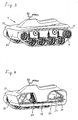
- Fig. 3 the same vehicle is shown in a perspective view, in which the shape of the vehicle body 1 with the watertight hull 23 and the deck 21 are more readily apparent.
- the volume of this watertight hull 23 is sufficient for the vehicle to swim in water.
- the upper runs 11 of the tracks of the swimming vehicle are above the water surface, so that the tracks can propel the swimming vehicle as well.
- Fig. 4 shows the same vehicle in a sectional perspective view, where the hull 23 and the deck 21 of the body are cut open according to the plane IV-IV indicated in Fig. 2 , opening the view to the inside of the vehicle.
- the vehicle body comprises a frame structure 24, to which the hull 23 and the deck 21 are mounted.
- the footrests 19 are an integral part of the deck 21 and each of them is situated in a recess in the deck 21.
- An internal combustion engine and gearbox assembly 25 is supported on the frame as well.
- This assembly 25 is best arranged in the middle of the vehicle, so that its center of gravity is perpendicularly above the center of gravity of the vehicle's footprint. In the straight direction of travel, the distance of the combustion engine and gearbox assembly 25 from the middle of the ground engaging lower runs 10 of the tracks does preferably not exceed 30% of their length. The same applies for the combustion engine alone if there is no gearbox or if a detached gearbox is used.
- a transmission 26 which connects a shaft of the combustion engine to the drive wheels 7 of the tracks via a differential gearing 27 is shown as well.
- the combustion engine might drive a generator producing electricity, the drive wheels being driven by electromotors, or the combustion engine might drive a hydraulic pump, the drive wheels being driven by hydraulic motors, for example.
- the steering system requires means to control the differential speed between the two tracks. For each of the different drive technologies various steering systems for full-track vehicles are already known to the one skilled in the art.
Landscapes
- Engineering & Computer Science (AREA)
- Chemical & Material Sciences (AREA)
- Combustion & Propulsion (AREA)
- Transportation (AREA)
- Mechanical Engineering (AREA)
- Automatic Cycles, And Cycles In General (AREA)
- Non-Deflectable Wheels, Steering Of Trailers, Or Other Steering (AREA)
- Vehicle Body Suspensions (AREA)
- Steering Devices For Bicycles And Motorcycles (AREA)
- Motorcycle And Bicycle Frame (AREA)
Claims (12)
- Kettengeländefahrzeug mit einem Fahrzeugkörper (1) mit einem Vorderende (2) und einem Hinterende (3), die seine gerade Fahrtrichtung bestimmen, einem Paar den Boden berührender endloser Ketten (5), die parallel zur geraden Fahrtrichtung drehbar um Kettenräder (6, 7, 8, 9) montiert sind und den Fahrzeugkörper (1) vollständig tragen, wobei die Ketten (5) jeweils ein Obertrum (11) und ein den Boden berührendes Untertrum (10) aufweisen und die Kettenräder Stützräder (9) umfassen, die das Obertrum (11) tragen, sowie Laufräder (6), die den Körper (1) auf der Innenfläche des Untertrums (10) der jeweiligen Kette (5) abstützen, mit Aufhängungsmitteln (13), an denen die Laufräder (6) elastisch am Körper (1) aufgehängt sind, einem Verbrennungsmotor (25), der mit den Ketten (5) wirkverbunden ist, um diese anzutreiben, einem auf dem Körper (1) abgestützten Fahrersitz (16) sowie Geschwindigkeitssteuerungsmitteln (30) und Lenkmitteln (15), die mit den Ketten (5) wirkverbunden und dazu eingerichtet sind, zur Steuerung der Geschwindigkeit bzw. zum Lenken des Fahrzeugs die Gleichlaufgeschwindigkeit und die Differenzgeschwindigkeit der Ketten (5) zu steuern, wobei das Lenkmittel eine Lenkstange (15) ist, die vor dem Fahrersitz (16) drehbar am Körper montiert und dafür eingerichtet ist, nach links oder rechts gedreht zu werden, zum Lenken nach links bzw. rechts, dadurch gekennzeichnet, dass
der Fahrersitz vom Grätschsitz-Typ (16) ist und in einer solchen Position angeordnet ist, dass die Abweichung der vorgesehenen Sitzposition des Fahrers von der Mitte eines den Boden berührenden Untertrums (10) der Ketten in der geraden Fahrtrichtung 30 % der Länge desselben nicht übersteigt, dass links und rechts vom Fahrersitz (16) Fussrasten (19) für den linken und rechten Fuss des Fahrers angeordnet sind, die sich hinter der Lenkstange (15) zwischen den Ketten (5) und senkrecht unter dem Obertrum (11) der Ketten befinden und eine stehende Fahrhaltung des Fahrers gestatten, dass die Lenkstange gegenüber dem Fahrzeugkörper (1) um eine einzige Drehachse drehbar ist, so dass sie vom Fahrer benutzbar ist, um Kräfte auf den Fahrzeugkörper (1) auszuüben, und dass Geschwindigkeitssteuerungsmittel (30) an der Lenkstange (15) angebracht sind zur manuellen Steuerung der Geschwindigkeit des Fahrzeugs durch den Fahrer. - Kettengeländefahrzeug nach Anspruch 1, weiter beinhaltend ein Bremssystem mit an der Lenkstange angebrachten Bremsbetätigungsmitteln (31) zum manuellen Bremsen.
- Kettengeländefahrzeug nach Anspruch 1, wobei die Aufhängungsmittel (13) dazu eingerichtet sind, eine senkrechte Auslenkung der Laufräder (6) gegenüber dem Körper von mindestens 10 cm zu gestatten.
- Kettengeländefahrzeug nach Anspruch 1, wobei die Laufräder (6) mittels elastischer Aufhängungsmittel (13) einzeln am Körper (1) aufgehängt sind.
- Kettengeländefahrzeug nach Anspruch 1, wobei die Länge der den Boden berührenden Untertrumme (10) der Ketten 2 m nicht übersteigt.
- Kettengeländefahrzeug nach Anspruch 1, wobei dessen Gewicht ohne Treibstoff 450 kg nicht übersteigt.
- Kettengeländefahrzeug nach Anspruch 1, wobei der Körper einen wasserdichten Rumpf (23) aufweist, dessen Volumen genügend gross ist, damit das Fahrzeug im Wasser schwimmt.
- Kettengeländefahrzeug nach Anspruch 7, wobei das Obertrum (11) der Ketten des schwimmenden Fahrzeugs über der Wasseroberfläche liegt.
- Kettengeländefahrzeug nach Anspruch 1, wobei der Aufbau (1) ein im Wesentlichen geschlossenes Deck (21) aufweist und die Fussstützen (9) jeweils in einer entsprechenden Vertiefung im Deck angeordnet sind.
- Kettengeländefahrzeug nach Anspruch 1, wobei der Verbrennungsmotor (25) in einer solchen Position am Körper (1) montiert ist, dass der Abstand seines Schwerpunkts von der Mitte eines den Boden berührenden Untertrums (11) der Ketten (5) in der geraden Fahrtrichtung 30 % der Länge desselben nicht übersteigt.
- Kettengeländefahrzeug nach Anspruch 1, wobei die Lenkstange einen linken und einen rechten Griff (17) für die linke bzw. rechte Hand des Fahrers aufweist und die Geschwindigkeitssteuerungsmittel (30) zur manuellen Steuerung der Geschwindigkeit einem der Griffe (17) zugeordnet sind.
- Kettengeländefahrzeug nach Anspruch 11, weiter enthaltend ein Bremssystem mit Bremsbetätigungsmitteln (31), die zum manuellen Bremsen in der Nähe mindestens eines der Griffe (17) angeordnet sind.
Applications Claiming Priority (2)
| Application Number | Priority Date | Filing Date | Title |
|---|---|---|---|
| US11/035,925 US7131507B2 (en) | 2005-01-14 | 2005-01-14 | Tracked ATV |
| PCT/CH2006/000001 WO2006074559A1 (en) | 2005-01-14 | 2006-01-03 | Tracked atv |
Publications (2)
| Publication Number | Publication Date |
|---|---|
| EP1836087A1 EP1836087A1 (de) | 2007-09-26 |
| EP1836087B1 true EP1836087B1 (de) | 2011-11-09 |
Family
ID=35976507
Family Applications (1)
| Application Number | Title | Priority Date | Filing Date |
|---|---|---|---|
| EP06700007A Expired - Lifetime EP1836087B1 (de) | 2005-01-14 | 2006-01-03 | Kettengeländefahrzeug |
Country Status (10)
| Country | Link |
|---|---|
| US (1) | US7131507B2 (de) |
| EP (1) | EP1836087B1 (de) |
| JP (1) | JP5005546B2 (de) |
| CN (1) | CN101102930B (de) |
| AT (1) | ATE532697T1 (de) |
| AU (1) | AU2006206010B2 (de) |
| CA (1) | CA2593339C (de) |
| ES (1) | ES2375570T3 (de) |
| RU (1) | RU2421363C2 (de) |
| WO (1) | WO2006074559A1 (de) |
Families Citing this family (40)
| Publication number | Priority date | Publication date | Assignee | Title |
|---|---|---|---|---|
| JP4796400B2 (ja) * | 2006-02-01 | 2011-10-19 | クラリオン株式会社 | 車両速度制御装置および同装置における目標速度設定方法ならびにプログラム |
| WO2008094911A1 (en) * | 2007-01-29 | 2008-08-07 | Paul Wilson | Tracked amphibious vehicle and adaptable amphibious tracking system |
| US7874386B2 (en) * | 2007-05-11 | 2011-01-25 | Pinhas Ben-Tzvi | Hybrid mobile robot |
| US7845443B2 (en) * | 2007-09-25 | 2010-12-07 | David K. Liberty | Low surface impact skid steered all terrain vehicle |
| CA2606039C (en) * | 2007-10-03 | 2016-03-29 | Camoplast Inc. | A track assembly for an all-terrain vehicle |
| US8844665B2 (en) * | 2007-12-27 | 2014-09-30 | Swissauto Powersport Llc | Skid steered all terrain vehicle |
| DE102008016282B3 (de) * | 2008-03-28 | 2009-09-10 | Brunn, Eberhard, Dr. | Schneefahrzeug |
| ITTO20090118A1 (it) * | 2009-02-19 | 2010-08-20 | Giuseppe Rosso | Cingolatura ammortizzata |
| WO2011081617A1 (en) * | 2009-12-30 | 2011-07-07 | Flowers Ip, Llc | Electronic steering assembly for dual motor vehicle |
| JP5870399B2 (ja) * | 2010-04-15 | 2016-03-01 | マーテル,イヴォン | 小型牽引装置 |
| US9821865B2 (en) | 2010-04-15 | 2017-11-21 | Yvon Martel | Compact pulling apparatus |
| CN103189271B (zh) * | 2010-10-29 | 2016-04-06 | 庞巴迪动力产品公司 | 雪地机动车悬架负载调节机构 |
| CN103596834B (zh) * | 2011-04-13 | 2017-12-01 | Bpg动力有限公司 | 用于个人履带车辆的悬挂组件 |
| CA2751184A1 (en) * | 2011-08-31 | 2013-02-28 | Gautier Arcouette | Dual track vehicle |
| KR102002202B1 (ko) | 2012-10-19 | 2019-07-19 | 이본 마르텔 | 트랙들이 나란한 컴팩트 드라이브 유니트 |
| RU2534202C2 (ru) * | 2013-02-19 | 2014-11-27 | Общество с ограниченной ответственностью "Арктик Инжиниринг" (ООО "Арктик Инжиниринг") | Малогабаритный всесезонный универсальный гусеничный вездеход |
| WO2014160728A2 (en) | 2013-03-25 | 2014-10-02 | Polaris Industries Inc. | Tracked all-terrain vehicle |
| SE537037C2 (sv) * | 2013-04-29 | 2014-12-16 | BAE Systems Hägglunds Aktiebolag | Fjädringssystem för bandfordon samt ett bandfordon med sådant fjädringssystem |
| JP6458800B2 (ja) * | 2013-07-11 | 2019-01-30 | マーテル,イヴォン | 小型牽引装置{compact pulling apparatus} |
| KR101642332B1 (ko) * | 2014-10-08 | 2016-07-26 | 금오공과대학교 산학협력단 | 무한궤도 |
| CN105292285A (zh) * | 2015-11-24 | 2016-02-03 | 冯林 | 一种管道内用于拖拽的机器人平台 |
| CN105292286A (zh) * | 2015-11-24 | 2016-02-03 | 冯林 | 一种基于杠杆组合支撑的履带行走机构 |
| KR102623758B1 (ko) | 2016-02-05 | 2024-01-10 | 두산 밥캣 노스 아메리카, 인크. | 소형 로더 |
| CN106005070A (zh) * | 2016-06-30 | 2016-10-12 | 长春工业大学 | 一种接地比压低的履带行走装置 |
| CN106114665A (zh) * | 2016-06-30 | 2016-11-16 | 长春工业大学 | 一种履带车辆负重轮及个数的分布方法 |
| US10730551B2 (en) | 2016-08-09 | 2020-08-04 | Polaris Industries Inc. | Tracked all-terrain vehicle |
| US10604200B2 (en) | 2016-12-14 | 2020-03-31 | Ontario Drive & Gear Limited | All-terrain vehicle |
| CA2967149C (en) | 2016-12-21 | 2024-04-30 | Peter Derek Visscher | Vehicle drive transmission and electrically assisted steering system |
| DE102017007342B4 (de) | 2017-08-03 | 2022-10-06 | Bruno Walter | Schneefahrzeug |
| RU183927U1 (ru) * | 2017-11-23 | 2018-10-09 | федеральное государственное бюджетное образовательное учреждение высшего образования "Алтайский государственный технический университет им. И.И. Ползунова" (АлтГТУ) | Малогабаритное гусеничное транспортное средство |
| RU183959U1 (ru) * | 2017-12-07 | 2018-10-10 | федеральное государственное бюджетное образовательное учреждение высшего образования "Алтайский государственный технический университет им. И.И. Ползунова" (АлтГТУ) | Малогабаритный гусеничный транспортер |
| CN108001539A (zh) * | 2017-12-14 | 2018-05-08 | 重庆蒙诺工程机械有限公司 | 一种稳定的履带车底盘结构 |
| US11148745B1 (en) * | 2019-02-26 | 2021-10-19 | Gregory Parker | Hydraulic drive powered endless track drive motorcycle |
| US11753093B2 (en) | 2019-04-09 | 2023-09-12 | Cnh Industrial America Llc | Suspension system for a track-driven work vehicle with pivoting roller wheel assemblies |
| US11618515B2 (en) | 2019-04-09 | 2023-04-04 | Cnh Industrial America Llc | Suspension system for a track-driven work vehicle with tandem rear idler/roller |
| RU2741670C1 (ru) * | 2020-03-31 | 2021-01-28 | Сергей Александрович Акимов | Моторама транспортного средства и ее применение |
| RU2739930C1 (ru) * | 2020-03-31 | 2020-12-29 | Сергей Александрович Акимов | Тихоходное малогабаритное транспортное средство и его применения |
| RU2739627C1 (ru) * | 2020-03-31 | 2020-12-28 | Сергей Александрович Акимов | Тяга рычага или педали управления транспортного средства и трансмиссия транспортного средства |
| CN111572656B (zh) * | 2020-05-08 | 2021-04-27 | 山东国兴智能科技股份有限公司 | 一种具备阻尼缓冲特性的悬挂系统及履带式移动平台 |
| CN115123503B (zh) * | 2022-07-29 | 2025-03-07 | 中国海洋大学 | 一种全地形海底采矿车行走装置 |
Family Cites Families (25)
| Publication number | Priority date | Publication date | Assignee | Title |
|---|---|---|---|---|
| DE717514C (de) | 1939-06-29 | 1942-02-16 | Nsu Werke Ag | Motorfahrzeug |
| US2373316A (en) * | 1941-10-02 | 1945-04-10 | Landy Arney | Endless crawler tread cycle |
| US2656904A (en) * | 1950-06-07 | 1953-10-27 | Grenier Joseph Wilfrid | Clutch and brake control for endless track vehicles |
| US3385255A (en) * | 1966-05-10 | 1968-05-28 | Thomas N Barka | Vehicle drive system |
| US3446303A (en) * | 1966-06-22 | 1969-05-27 | Outboard Marine Corp | Endless track vehicle |
| US3698500A (en) * | 1969-05-19 | 1972-10-17 | Albert T Jernigan | Two-track vehicle |
| US3688858A (en) * | 1969-09-12 | 1972-09-05 | Outboard Marine Corp | All-terrain vehicle |
| US3776325A (en) * | 1970-11-27 | 1973-12-04 | Outboard Marine Corp | All-terrain vehicle |
| US3771616A (en) * | 1972-01-26 | 1973-11-13 | A Parodi | Snow vehicle |
| US4671774A (en) * | 1983-01-28 | 1987-06-09 | Owsen Paul J | All terrain vehicle |
| JPS6223878A (ja) * | 1985-07-23 | 1987-01-31 | Suzuki Motor Co Ltd | 走行車両の無限軌道帯装置 |
| JPS63279979A (ja) * | 1987-05-11 | 1988-11-17 | Honda Motor Co Ltd | クロ−ラベルト式車両 |
| SU1444233A1 (ru) * | 1987-05-27 | 1988-12-15 | В. Н. Завь лов и О. В. Нифонтов | Легкий одноколейный вездеход |
| JPS63305013A (ja) * | 1987-06-05 | 1988-12-13 | Fueibaa:Kk | キャタピラ推進式高速船舶 |
| US4953492A (en) * | 1989-06-21 | 1990-09-04 | Fmc Corporation | Water supporting and propulsion systems |
| US5305846A (en) * | 1992-10-29 | 1994-04-26 | Martin William D | Motorized trackboard |
| CA2141777A1 (en) * | 1995-02-03 | 1996-08-04 | Randy Lepard | Tracked atv |
| RU4272U1 (ru) * | 1996-03-05 | 1997-06-16 | Владимир Петрович Толстоухов | Гусеничный мотоцикл |
| JP3795142B2 (ja) * | 1996-07-26 | 2006-07-12 | 本田技研工業株式会社 | クローラ式乗用管理機 |
| US6006847A (en) * | 1997-02-18 | 1999-12-28 | Knight; Doyle D | Endless track structure for light wheeled vehicle |
| IT236041Y1 (it) * | 1997-04-16 | 2000-07-26 | Aris Spa | Attrezzatura ausiliaria di galleggiamento, propulsione e governo perveicoli polivalenti con funzione anfibia. |
| JPH11278024A (ja) * | 1998-01-29 | 1999-10-12 | Kido Kosakusho:Kk | 自在走行用乗物 |
| US6615939B1 (en) | 2001-03-07 | 2003-09-09 | David Karales | ATV track conversion |
| US20040159475A1 (en) * | 2003-02-13 | 2004-08-19 | Moor, Halley Ray | Vehicular powered tracks |
| EP1795420B1 (de) * | 2005-12-08 | 2010-09-08 | Nissin Kogyo Co., Ltd. | Verriegeltes Bremssystem für Fahrzeug mit Lenkstange |
-
2005
- 2005-01-14 US US11/035,925 patent/US7131507B2/en not_active Expired - Lifetime
-
2006
- 2006-01-03 WO PCT/CH2006/000001 patent/WO2006074559A1/en not_active Ceased
- 2006-01-03 CA CA2593339A patent/CA2593339C/en not_active Expired - Lifetime
- 2006-01-03 ES ES06700007T patent/ES2375570T3/es not_active Expired - Lifetime
- 2006-01-03 JP JP2007550651A patent/JP5005546B2/ja not_active Expired - Lifetime
- 2006-01-03 EP EP06700007A patent/EP1836087B1/de not_active Expired - Lifetime
- 2006-01-03 RU RU2007125859/11A patent/RU2421363C2/ru not_active IP Right Cessation
- 2006-01-03 AT AT06700007T patent/ATE532697T1/de active
- 2006-01-03 CN CN2006800023473A patent/CN101102930B/zh not_active Expired - Lifetime
- 2006-01-03 AU AU2006206010A patent/AU2006206010B2/en not_active Expired
Also Published As
| Publication number | Publication date |
|---|---|
| WO2006074559A1 (en) | 2006-07-20 |
| AU2006206010A1 (en) | 2006-07-20 |
| US20060157290A1 (en) | 2006-07-20 |
| CN101102930B (zh) | 2012-09-19 |
| EP1836087A1 (de) | 2007-09-26 |
| AU2006206010B2 (en) | 2011-06-09 |
| US7131507B2 (en) | 2006-11-07 |
| RU2007125859A (ru) | 2009-02-20 |
| JP2008526604A (ja) | 2008-07-24 |
| CN101102930A (zh) | 2008-01-09 |
| ES2375570T3 (es) | 2012-03-02 |
| ATE532697T1 (de) | 2011-11-15 |
| CA2593339A1 (en) | 2006-07-20 |
| CA2593339C (en) | 2013-06-04 |
| RU2421363C2 (ru) | 2011-06-20 |
| JP5005546B2 (ja) | 2012-08-22 |
Similar Documents
| Publication | Publication Date | Title |
|---|---|---|
| EP1836087B1 (de) | Kettengeländefahrzeug | |
| JP3853654B2 (ja) | キャンバリング車両およびその機構 | |
| US20090289437A1 (en) | Vehicle with three wheels | |
| AU2013344834B2 (en) | Vehicle stability, steering, ride characteristics and control | |
| US4903857A (en) | Leaning vehicle with centrifugal force compensation | |
| CN105813922B (zh) | 具有倾斜框架的车辆 | |
| US5485893A (en) | Vehicle | |
| US9527546B2 (en) | Vehicle having positional control function | |
| US7871095B2 (en) | Two wheel steering bicycle with each wheel having its own steering control operated by rider's left and right hand respectively and rider positioned facing an angle greater than zero and less than ninty degrees with respect to the direction of motion | |
| JP2008540216A (ja) | 乗物、これに使用されるハブ、自転車に乗るための学習方法、三輪車、四輪車、及び自転車を安定させる安定方法 | |
| US20030214113A1 (en) | Vehicle having independently articulating rear frame members | |
| JP2008502536A (ja) | スキースレッジ | |
| WO2006009958A2 (en) | Cambering vehicle with improved handlebar, footboard ergonomics, heel support, and cambering joint | |
| US11364966B2 (en) | Tricycle with dual steering handlebars | |
| CN108883808B (zh) | 双轮车 | |
| JPH0453351Y2 (de) | ||
| KR100837445B1 (ko) | 사륜 자전거용 조향구조 | |
| WO2023279408A1 (zh) | 带有转向辅助结构的遥控雪地摩托车 | |
| JPH01101285A (ja) | 走行装置 |
Legal Events
| Date | Code | Title | Description |
|---|---|---|---|
| PUAI | Public reference made under article 153(3) epc to a published international application that has entered the european phase |
Free format text: ORIGINAL CODE: 0009012 |
|
| 17P | Request for examination filed |
Effective date: 20070616 |
|
| AK | Designated contracting states |
Kind code of ref document: A1 Designated state(s): AT BE BG CH CY CZ DE DK EE ES FI FR GB GR HU IE IS IT LI LT LU LV MC NL PL PT RO SE SI SK TR |
|
| DAX | Request for extension of the european patent (deleted) | ||
| 17Q | First examination report despatched |
Effective date: 20080729 |
|
| GRAP | Despatch of communication of intention to grant a patent |
Free format text: ORIGINAL CODE: EPIDOSNIGR1 |
|
| RAP1 | Party data changed (applicant data changed or rights of an application transferred) |
Owner name: SWISSAUTO OFFROAD AG |
|
| RAP1 | Party data changed (applicant data changed or rights of an application transferred) |
Owner name: SWISSAUTO POWERSPORT LLC |
|
| GRAS | Grant fee paid |
Free format text: ORIGINAL CODE: EPIDOSNIGR3 |
|
| GRAA | (expected) grant |
Free format text: ORIGINAL CODE: 0009210 |
|
| AK | Designated contracting states |
Kind code of ref document: B1 Designated state(s): AT BE BG CH CY CZ DE DK EE ES FI FR GB GR HU IE IS IT LI LT LU LV MC NL PL PT RO SE SI SK TR |
|
| REG | Reference to a national code |
Ref country code: GB Ref legal event code: FG4D |
|
| REG | Reference to a national code |
Ref country code: CH Ref legal event code: EP |
|
| REG | Reference to a national code |
Ref country code: IE Ref legal event code: FG4D |
|
| REG | Reference to a national code |
Ref country code: DE Ref legal event code: R096 Ref document number: 602006025693 Country of ref document: DE Effective date: 20120119 |
|
| REG | Reference to a national code |
Ref country code: NL Ref legal event code: VDEP Effective date: 20111109 |
|
| REG | Reference to a national code |
Ref country code: SE Ref legal event code: TRGR |
|
| REG | Reference to a national code |
Ref country code: ES Ref legal event code: FG2A Ref document number: 2375570 Country of ref document: ES Kind code of ref document: T3 Effective date: 20120302 |
|
| LTIE | Lt: invalidation of european patent or patent extension |
Effective date: 20111109 |
|
| PG25 | Lapsed in a contracting state [announced via postgrant information from national office to epo] |
Ref country code: LT Free format text: LAPSE BECAUSE OF FAILURE TO SUBMIT A TRANSLATION OF THE DESCRIPTION OR TO PAY THE FEE WITHIN THE PRESCRIBED TIME-LIMIT Effective date: 20111109 Ref country code: IS Free format text: LAPSE BECAUSE OF FAILURE TO SUBMIT A TRANSLATION OF THE DESCRIPTION OR TO PAY THE FEE WITHIN THE PRESCRIBED TIME-LIMIT Effective date: 20120309 |
|
| PG25 | Lapsed in a contracting state [announced via postgrant information from national office to epo] |
Ref country code: BE Free format text: LAPSE BECAUSE OF FAILURE TO SUBMIT A TRANSLATION OF THE DESCRIPTION OR TO PAY THE FEE WITHIN THE PRESCRIBED TIME-LIMIT Effective date: 20111109 Ref country code: LV Free format text: LAPSE BECAUSE OF FAILURE TO SUBMIT A TRANSLATION OF THE DESCRIPTION OR TO PAY THE FEE WITHIN THE PRESCRIBED TIME-LIMIT Effective date: 20111109 Ref country code: NL Free format text: LAPSE BECAUSE OF FAILURE TO SUBMIT A TRANSLATION OF THE DESCRIPTION OR TO PAY THE FEE WITHIN THE PRESCRIBED TIME-LIMIT Effective date: 20111109 Ref country code: SI Free format text: LAPSE BECAUSE OF FAILURE TO SUBMIT A TRANSLATION OF THE DESCRIPTION OR TO PAY THE FEE WITHIN THE PRESCRIBED TIME-LIMIT Effective date: 20111109 Ref country code: PT Free format text: LAPSE BECAUSE OF FAILURE TO SUBMIT A TRANSLATION OF THE DESCRIPTION OR TO PAY THE FEE WITHIN THE PRESCRIBED TIME-LIMIT Effective date: 20120309 Ref country code: PL Free format text: LAPSE BECAUSE OF FAILURE TO SUBMIT A TRANSLATION OF THE DESCRIPTION OR TO PAY THE FEE WITHIN THE PRESCRIBED TIME-LIMIT Effective date: 20111109 Ref country code: GR Free format text: LAPSE BECAUSE OF FAILURE TO SUBMIT A TRANSLATION OF THE DESCRIPTION OR TO PAY THE FEE WITHIN THE PRESCRIBED TIME-LIMIT Effective date: 20120210 |
|
| PG25 | Lapsed in a contracting state [announced via postgrant information from national office to epo] |
Ref country code: CY Free format text: LAPSE BECAUSE OF FAILURE TO SUBMIT A TRANSLATION OF THE DESCRIPTION OR TO PAY THE FEE WITHIN THE PRESCRIBED TIME-LIMIT Effective date: 20111109 |
|
| PG25 | Lapsed in a contracting state [announced via postgrant information from national office to epo] |
Ref country code: CZ Free format text: LAPSE BECAUSE OF FAILURE TO SUBMIT A TRANSLATION OF THE DESCRIPTION OR TO PAY THE FEE WITHIN THE PRESCRIBED TIME-LIMIT Effective date: 20111109 Ref country code: EE Free format text: LAPSE BECAUSE OF FAILURE TO SUBMIT A TRANSLATION OF THE DESCRIPTION OR TO PAY THE FEE WITHIN THE PRESCRIBED TIME-LIMIT Effective date: 20111109 Ref country code: SK Free format text: LAPSE BECAUSE OF FAILURE TO SUBMIT A TRANSLATION OF THE DESCRIPTION OR TO PAY THE FEE WITHIN THE PRESCRIBED TIME-LIMIT Effective date: 20111109 Ref country code: BG Free format text: LAPSE BECAUSE OF FAILURE TO SUBMIT A TRANSLATION OF THE DESCRIPTION OR TO PAY THE FEE WITHIN THE PRESCRIBED TIME-LIMIT Effective date: 20120209 Ref country code: DK Free format text: LAPSE BECAUSE OF FAILURE TO SUBMIT A TRANSLATION OF THE DESCRIPTION OR TO PAY THE FEE WITHIN THE PRESCRIBED TIME-LIMIT Effective date: 20111109 |
|
| PG25 | Lapsed in a contracting state [announced via postgrant information from national office to epo] |
Ref country code: MC Free format text: LAPSE BECAUSE OF NON-PAYMENT OF DUE FEES Effective date: 20120131 Ref country code: RO Free format text: LAPSE BECAUSE OF FAILURE TO SUBMIT A TRANSLATION OF THE DESCRIPTION OR TO PAY THE FEE WITHIN THE PRESCRIBED TIME-LIMIT Effective date: 20111109 |
|
| PLBE | No opposition filed within time limit |
Free format text: ORIGINAL CODE: 0009261 |
|
| STAA | Information on the status of an ep patent application or granted ep patent |
Free format text: STATUS: NO OPPOSITION FILED WITHIN TIME LIMIT |
|
| REG | Reference to a national code |
Ref country code: AT Ref legal event code: MK05 Ref document number: 532697 Country of ref document: AT Kind code of ref document: T Effective date: 20111109 |
|
| 26N | No opposition filed |
Effective date: 20120810 |
|
| REG | Reference to a national code |
Ref country code: IE Ref legal event code: MM4A |
|
| REG | Reference to a national code |
Ref country code: DE Ref legal event code: R097 Ref document number: 602006025693 Country of ref document: DE Effective date: 20120810 |
|
| PG25 | Lapsed in a contracting state [announced via postgrant information from national office to epo] |
Ref country code: IE Free format text: LAPSE BECAUSE OF NON-PAYMENT OF DUE FEES Effective date: 20120103 Ref country code: AT Free format text: LAPSE BECAUSE OF FAILURE TO SUBMIT A TRANSLATION OF THE DESCRIPTION OR TO PAY THE FEE WITHIN THE PRESCRIBED TIME-LIMIT Effective date: 20111109 |
|
| PG25 | Lapsed in a contracting state [announced via postgrant information from national office to epo] |
Ref country code: TR Free format text: LAPSE BECAUSE OF FAILURE TO SUBMIT A TRANSLATION OF THE DESCRIPTION OR TO PAY THE FEE WITHIN THE PRESCRIBED TIME-LIMIT Effective date: 20111109 |
|
| PG25 | Lapsed in a contracting state [announced via postgrant information from national office to epo] |
Ref country code: LU Free format text: LAPSE BECAUSE OF NON-PAYMENT OF DUE FEES Effective date: 20120103 |
|
| PG25 | Lapsed in a contracting state [announced via postgrant information from national office to epo] |
Ref country code: HU Free format text: LAPSE BECAUSE OF FAILURE TO SUBMIT A TRANSLATION OF THE DESCRIPTION OR TO PAY THE FEE WITHIN THE PRESCRIBED TIME-LIMIT Effective date: 20060103 |
|
| REG | Reference to a national code |
Ref country code: FR Ref legal event code: PLFP Year of fee payment: 11 |
|
| REG | Reference to a national code |
Ref country code: FR Ref legal event code: PLFP Year of fee payment: 12 |
|
| REG | Reference to a national code |
Ref country code: FR Ref legal event code: PLFP Year of fee payment: 13 |
|
| PGFP | Annual fee paid to national office [announced via postgrant information from national office to epo] |
Ref country code: CH Payment date: 20171213 Year of fee payment: 13 |
|
| REG | Reference to a national code |
Ref country code: CH Ref legal event code: PL |
|
| PG25 | Lapsed in a contracting state [announced via postgrant information from national office to epo] |
Ref country code: CH Free format text: LAPSE BECAUSE OF NON-PAYMENT OF DUE FEES Effective date: 20190131 Ref country code: LI Free format text: LAPSE BECAUSE OF NON-PAYMENT OF DUE FEES Effective date: 20190131 |
|
| PGFP | Annual fee paid to national office [announced via postgrant information from national office to epo] |
Ref country code: FI Payment date: 20241218 Year of fee payment: 20 |
|
| PGFP | Annual fee paid to national office [announced via postgrant information from national office to epo] |
Ref country code: GB Payment date: 20241219 Year of fee payment: 20 |
|
| PGFP | Annual fee paid to national office [announced via postgrant information from national office to epo] |
Ref country code: FR Payment date: 20241219 Year of fee payment: 20 |
|
| PGFP | Annual fee paid to national office [announced via postgrant information from national office to epo] |
Ref country code: SE Payment date: 20241219 Year of fee payment: 20 |
|
| PGFP | Annual fee paid to national office [announced via postgrant information from national office to epo] |
Ref country code: DE Payment date: 20241218 Year of fee payment: 20 |
|
| PGFP | Annual fee paid to national office [announced via postgrant information from national office to epo] |
Ref country code: ES Payment date: 20250203 Year of fee payment: 20 |
|
| PGFP | Annual fee paid to national office [announced via postgrant information from national office to epo] |
Ref country code: IT Payment date: 20250107 Year of fee payment: 20 |
|
| REG | Reference to a national code |
Ref country code: DE Ref legal event code: R071 Ref document number: 602006025693 Country of ref document: DE |
|
| REG | Reference to a national code |
Ref country code: GB Ref legal event code: PE20 Expiry date: 20260102 |
|
| REG | Reference to a national code |
Ref country code: ES Ref legal event code: FD2A Effective date: 20260128 |