EP1832501A2 - Robot à chenilles - Google Patents
Robot à chenilles Download PDFInfo
- Publication number
- EP1832501A2 EP1832501A2 EP07250985A EP07250985A EP1832501A2 EP 1832501 A2 EP1832501 A2 EP 1832501A2 EP 07250985 A EP07250985 A EP 07250985A EP 07250985 A EP07250985 A EP 07250985A EP 1832501 A2 EP1832501 A2 EP 1832501A2
- Authority
- EP
- European Patent Office
- Prior art keywords
- crawler
- triangular
- subordinate
- crawler device
- link
- Prior art date
- Legal status (The legal status is an assumption and is not a legal conclusion. Google has not performed a legal analysis and makes no representation as to the accuracy of the status listed.)
- Granted
Links
Images


Classifications
-
- B—PERFORMING OPERATIONS; TRANSPORTING
- B62—LAND VEHICLES FOR TRAVELLING OTHERWISE THAN ON RAILS
- B62D—MOTOR VEHICLES; TRAILERS
- B62D55/00—Endless track vehicles
- B62D55/06—Endless track vehicles with tracks without ground wheels
- B62D55/065—Multi-track vehicles, i.e. more than two tracks
- B62D55/0655—Articulated endless track vehicles
-
- B—PERFORMING OPERATIONS; TRANSPORTING
- B62—LAND VEHICLES FOR TRAVELLING OTHERWISE THAN ON RAILS
- B62D—MOTOR VEHICLES; TRAILERS
- B62D55/00—Endless track vehicles
- B62D55/06—Endless track vehicles with tracks without ground wheels
- B62D55/075—Tracked vehicles for ascending or descending stairs, steep slopes or vertical surfaces
-
- B—PERFORMING OPERATIONS; TRANSPORTING
- B62—LAND VEHICLES FOR TRAVELLING OTHERWISE THAN ON RAILS
- B62D—MOTOR VEHICLES; TRAILERS
- B62D55/00—Endless track vehicles
- B62D55/08—Endless track units; Parts thereof
- B62D55/18—Tracks
-
- B—PERFORMING OPERATIONS; TRANSPORTING
- B62—LAND VEHICLES FOR TRAVELLING OTHERWISE THAN ON RAILS
- B62D—MOTOR VEHICLES; TRAILERS
- B62D55/00—Endless track vehicles
- B62D55/08—Endless track units; Parts thereof
- B62D55/30—Track-tensioning means
-
- B—PERFORMING OPERATIONS; TRANSPORTING
- B62—LAND VEHICLES FOR TRAVELLING OTHERWISE THAN ON RAILS
- B62D—MOTOR VEHICLES; TRAILERS
- B62D59/00—Trailers with driven ground wheels or the like
- B62D59/04—Trailers with driven ground wheels or the like driven from propulsion unit on trailer
Definitions
- aspects of the present invention relate to a robot using crawlers as moving devices, and more particularly to a crawler robot having, on both sides of a robot main body, crawlers driven in a triangular form to thereby form a triangular crawler device, and further, including a small subordinate crawler device rotatably connected with the triangular crawler device by a link.
- Examples of the related art robots include stationary robots mainly installed in the production lines of plants, and movable robots equipped with moving devices of various types; the related art movable robots mainly adopt either a caterpillar type or a leg type moving system.
- vehicles travel by using tires as in the case of automobiles, or by using caterpillars formed of iron or rubber belts as in the case of tanks.
- the belts used in the latter type of traveling system are called crawlers (or crawler belts).
- crawlers or crawler belts.
- the ground contact area is larger than in the case of traveling by using tires. Therefore, it is possible to markedly reduce the applied weight (ground contact pressure) per unit area.
- ground contact pressure applied weight
- Movable robots are expected to be applied to rescue work and operations in extreme environments; thus, high mobility and high reliability are required of the traveling mechanism of a movable robot, which is expected to be capable of climbing over as high an obstacle as possible.
- a movable robot to climb over a high obstacle displacement of the center of gravity thereof is important, and, in this regard, various related art systems for movable robots of this type have been proposed.
- JP 2005-335681 A discloses a robot having on both sides thereof crawlers arranged in a square form
- JP 08-133141 A discloses a crawler robot having one sprocket for driving a crawler belt, two sets of rotating wheels in each of which two rotating wheels are integrally rotatable around the same axis, and one triangular mechanism in which three rotating wheels are arranged at the apexes of an equilateral triangle so as to be rotatable around the center of gravity thereof; those are arranged at the apexes of a square which is of a configuration symmetrical with respect to a center line and which does not involve interference between the rotating motions of the above-mentioned components, around which the crawler belt is wrapped.
- crawler robots While capable of traveling on an irregular ground or the like, such a related art caterpillar type crawler robot as mentioned above involves a complicated mechanism to climb over, for example, a high obstacle, resulting in an increase in size and a problem in terms of energy consumption and mobility. Further, many crawler robots are of a structure vertically asymmetrical, so when turned upside down, they become incapable of operation.
- aspects of the present invention provide a crawler robot which is equipped with a center-of-gravity-displacement mechanism to be used when climbing over a high obstacle and which can be formed in an axial-rotational-symmetrical structure with no upside or downside in order to prevent the crawler robot from becoming substantially incapable of operation.
- the exemplary embodiments include a multi-degree-of-freedom robot structure equipped with a triangular crawler device having on both sides thereof frames with two right and left triangular crawlers fixed to the same rotation shaft and a small subordinate crawler device of a standard configuration connected therewith by a link. Movement of the crawler robot is effected by caterpillars of the triangular crawler device and those of the subordinate crawler device.
- the triangular crawler device has a larger weight than the subordinate crawler device, so when climbing over an obstacle, the former is raised by the latter and the link to a higher position, and after traversing the obstacle, the small, subordinate crawler is raised by folding the link, whereby it is possible to climb over the obstacle and effect displacement of the center of gravity.
- a crawler robot includes: a triangular crawler device having on both sides thereof crawlers wrapped around rollers arranged at apexes of triangular frames whose centers are connected together by a support shaft; a subordinate crawler device having on both sides thereof crawlers wrapped around at least two rollers of frames, which are connected together; and a link having at both ends thereof the support shaft of the triangular crawler device and the subordinate crawler device rotatably connected.
- another crawler robot is characterized in that the link is a one-joint link composed of a first link and a second link rotatably connected together.
- another crawler robot is characterized in that the triangular crawler device and the subordinate crawler device differ from each other in weight, and wherein the link rotates thereby displacing a center of gravity of the crawler robot as a whole.
- another crawler robot according to the exemplary embodiment is characterized in that the crawler robot can travel with both the triangular crawler device and the subordinate crawler device in contact with ground.
- another crawler robot according to the exemplary embodiment is characterized in that the link and the subordinate crawler device are accommodated within an outer peripheral edge of the triangular crawler device.
- another crawler robot according to the exemplary embodiment is characterized in that the crawler robot can travel with the subordinate crawler device raised by the triangular crawler device.
- another crawler robot according to the exemplary embodiment is characterized in that the crawler robot can travel with the triangular crawler device raised by the subordinate crawler device.
- another crawler robot is characterized in that the triangular crawler device is raised and placed on a step portion by the subordinate crawler device, and wherein the subordinate crawler device is raised up to the step portion by the triangular crawler device.
- another crawler robot is characterized in that the triangular frames are rotated around the support shaft to raise front portions of the surfaces of the triangular crawlers from ground, to thereby effect an operation of climbing over a step.
- another crawler robot is characterized in that the triangular crawler device is raised and placed on a step portion by the subordinate crawler device, and wherein the subordinate crawler device is raised up to the step portion by the triangular crawler device.
- another crawler robot is characterized in that the subordinate crawler device applies a pressure from a rear side, to substantially grip the surfaces of the triangular crawlers in contact with the ground, thereby configured to climb over a high step.
- another crawler robot is characterized in that the triangular crawler device is provided with crawler guides for causing the crawlers to protrude from within, which are retractable at midpoints of the three sides of the triangular crawler device.
- another crawler robot according to the exemplary embodiment is characterized in that with the crawler guides protruding, the crawler robot can travel through rotation of the frames of the triangular crawler device about the support shaft.
- another crawler robot is characterized in that the subordinate crawler device is equipped with a connecting means for connecting with another crawler robot, making it possible to bead together a plurality of crawler robots.
- a center-of-gravity-displacement mechanism is used in which the triangular crawler device and the subordinate crawler device are connected by a link, whereby it is possible to climb over a higher step as compared with the related art techniques.
- the representative dimension in the height direction is the height of the triangular crawler
- the height of the triangular crawler portion is approximately 20 cm, it is possible to easily climb over a step or an obstacle of a height in the range of normal human activity; otherwise, it is possible to operate the movable robot in various aspects, such as movement in a generally compact structure. Further, by making the link connecting the triangular crawler device with the subordinate crawler device foldable, it is possible to climb over a still higher step. Further, even when turned upside down, the robot is can be restored to the former state through cooperation of the triangular crawler device and the subordinate crawler device.
- a small crawler robot it is possible for a small crawler robot to climb over a high step, and further, to perform operations in various aspects without becoming substantially incapable of operation by virtue of a construction in which crawlers wrapped around rollers arranged at the apexes of triangular frames are provided on the right and left sides, with the center of the frames being connected by a support shaft to form a triangular crawler device, and in which crawlers wrapped around at least two rollers of frames are provided on the right and left sides to form a subordinate crawler device by connecting together the frames, with a support shaft of the triangular crawler device and the subordinate crawler device being rotatably connected with both ends of a link.
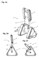
- FIGS. 1A and 1B are perspective views illustrating an operational aspect of an exemplary embodiment
- FIGS. 2A and 2B are diagrams illustrating another operational aspect of the exemplary embodiment, of which FIG. 2A is a perspective view and FIG. 2B is a conceptual drawing;
- FIGS. 3A through 3C are diagrams illustrating still another operational aspect of the exemplary embodiment, of which FIG. 3A is a perspective view, FIG. 3B is a conceptual drawing, and FIG. 3C is a conceptual drawing illustrating another operational aspect;
- FIG. 4 is a perspective view illustrating yet another operational aspect of the exemplary embodiment
- FIG. 5 is a perspective view illustrating an operational aspect of the exemplary embodiment when a step portion is to be climbed over;
- FIG. 6 is a perspective view illustrating another operational aspect of the exemplary embodiment when a step portion is to be climbed over;
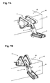
- FIGS. 7A and 7B are diagrams illustrating an operational aspect of the exemplary embodiment when a relatively high step is to be climbed over;
- FIG. 8 is a diagram illustrating an operational aspect of the exemplary embodiment in which guide rollers are caused to protrude from within a triangular crawler device to effect traveling in a manner analogous to that of wheels;
- FIG. 9 is a diagram illustrating another exemplary embodiment, in which traveling is effected with a plurality of crawler robots linked together.
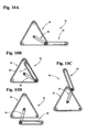
- FIGS. 10A through 10D are conceptual drawings illustrating still another exemplary embodiment, showing various operational aspects thereof.
- FIGS. 1A and 1B are perspective views showing one of various operational aspects of a crawler robot according to the exemplary embodiment, in which there is used a one-joint link composed of two links rotatably connected together.
- a crawler robot 1 is composed of a triangular crawler device 2 having triangular crawlers on both sides thereof, a subordinate crawler device 3 having standard type small crawlers on both sides thereof, and a one-joint link 4 connecting together the triangular crawler device 2 and the subordinate crawler device 3.
- both ends of a central support shaft 11 are supported by frames, each of which is composed of an inner triangular frame 12 and an outer triangular frame 13, with rollers 14 being provided at the apex portions of the frames.
- Elastic crawlers 15 formed of an elastic material such as rubber and serving as caterpillars are wrapped around the rollers, forming triangular crawlers, which are substantially triangular.
- At least one of the three rollers 14 supporting each triangular crawler is driven by a motor, whereby the elastic crawlers 15 circulate around the rollers 14 in a triangular form, enabling the crawler robot to advance, retreat, or stop by virtue of a frictional force generated at the surfaces of the elastic crawlers 15 in contact with the ground.
- a first triangular crawler 16 on one side and a second triangular crawler 17 on the other side can be driven independently, circulating the crawlers in the same direction or in opposite directions; further, it is also possible to cause only one crawler to advance or retreat, with the other kept at rest.
- at least one of the rollers 14 of each triangular crawler is driven by a motor; although not shown, the motor is arranged within each of the frames, between the outer triangular frame 13 and the inner triangular frame 12, as would be understood by one skilled in the art.
- a support shaft 21 of each roller 14 is movable within a radial guide groove 22 formed in the inner triangular frame 12 and the outer triangular frame 13, making it possible to effect positional adjustment, etc.
- first sensor case 18 and a second sensor case 19 which are rotatable with respect to the support shaft 11, with the peripheries of the sensor cases being protected by guards 20 serving also as tactile sensors.
- one end of a first arm 23 constituting the one-joint link 4 is rotatably supported at the intermediate portion of the central support shaft 11.
- a second arm 24 is rotatably supported; the second arm 24 can be arbitrarily rotated by a motor around an inner connection shaft with respect to the first arm 23, thereby forming the one-joint link 4.
- Support arms 25 and 26 are provided on both sides of the end portion of the second arm 24 so that the first arm 23 and the second arm 24 can rotate within a range, whereby a rotation space is defined between the two arms, with the first arm 23 being rotatably supported by a rotation shaft provided at the forward ends of the support arms 25 and 26.
- a front shaft 29 of the subordinate crawler device 3 which has on both sides thereof a first standard crawler 27 and a second standard crawler 28 which are small and of a standard type that have been widely used and in each of which a crawler is stretched between at least two rollers.
- the subordinate crawler device 3 is arbitrarily rotatable with respect to the second arm 24 by a motor (not shown) directly connected to the connection shaft 29 arranged inside the other end portion of the second arm 24.
- the first standard crawler 27 and the second standard crawler 28 are both stretched between a roller 30 provided on the front shaft 29 connected with the one-joint link 4 and a roller 32 provided on a rear shaft 31, and can be operated in the substantially same manner as related art crawlers by a motor (not shown) directly connected to the rear shaft 31.
- the crawler robot 1 described above can be used as a multi-degree-of-freedom robot that can be operated in various aspects as shown in FIGS. 2A through 9.
- FIG. 2B which is a frame drawing
- the first arm 23 of the one-joint link 4 extending from the central support shaft 11 of the triangular crawler device 2 is rotated to a first corner portion 35 of the triangular crawler device 2;
- the second arm 24 is bent around a rotation shaft 36 constituting the joint of the one-joint link 4;
- the end portion supporting the subordinate crawler device 3 is rotated toward a second corner portion 37 of the triangular crawler device 2;
- the portion of the subordinate crawler device 3 which extends from the front arm 29 to the rear shaft 31, supported by the second arm 24, is rotated so as to be situated at a third corner portion 38 side, whereby the one-joint link 4 and the subordinate crawler device 3 are accommodated within the outer peripheral edge of the triangular crawl
- the triangular crawler device 2 supports through the intermediation of the one-joint link 4 of the subordinate crawler device 3 at a position above the same; in the example shown in FIG. 3A, which is a perspective view, and FIG. 3B, which is a schematic view, the one-joint link 4 is extended with respect to the triangular crawler device 2 to support the subordinate crawler device 3, which is also extended upwardly, with the result that the crawler robot assumes the substantially highest position.
- FIG. 3A which is a perspective view
- FIG. 3B which is a schematic view
- the one-joint link 4 is further bent to bend the subordinate crawler 3 to support the subordinate crawler device 3 in a similarly bent fashion, whereby, with the height of the crawler robot as a whole being reduced, it is possible to upwardly support and move the subordinate crawler device 3 by the triangular crawler device 2.
- traveling is possible with the triangular crawler device 2 supported above the subordinate crawler device 3. That is, with the subordinate crawler device 3 being in a traveling aspect, the second arm 24 of the one-joint link 4 is bent sufficiently backwards to support the first arm substantially upwards, whereby the center of gravity of the triangular crawler device 2 is substantially positioned directly above the center of gravity of the subordinate crawler device 3, making it possible to perform traveling by the subordinate crawler device 3 in a stable state.
- the triangular crawler device 2 becomes substantially incapable of traveling, traveling is possible by the subordinate crawler device 3, and further, it is possible to perform various other operations.
- the crawler robot travels to a step-like structure 40, and the triangular crawler device 2 is raised by extending the one-joint link 4, placing it on a first step portion 41 of the step-like structure 40. Since the weight of the triangular crawler device 2 is sufficiently larger than that of the subordinate crawler device 3, when the triangular crawler device 2 is rotated in this state in a bent fashion so as to be reversed through reversal of the one-joint link 4, it is possible to perform the operation of raising the subordinate crawler device 3 and placing it on the first step portion 41. By repeating this, it is possible to travel while climbing over various obstacles.
- the crawler robot travels to a low step 39 through the substantially same operation as in the operational aspect of FIG. 1, and the triangular crawler device 2 is rotated around the support shaft 11 to raise from the ground the forward portions of the surfaces of the crawlers that have been in contact with the ground, thereby making it possible to climb over the step 39.
- the triangular crawler device 2 is pressed against a wall 45 of the structure 43 with the urging force exerted toward the wall 45 through the forward movement of the subordinate crawler device 3, and the triangular crawler device 2 is driven in the direction of an arrow Ain FIG. 7A while being gripped, and caused to move upwards on the vertical wall 45, and at the same time, the subordinate crawler device 3 is driven in the direction of an arrow B to advance, whereby the triangular crawler device 2 can move upwardly on the vertical wall 45.
- the triangular crawler device 2 can be moved onto the step portion 44 of the structure 43.
- the triangular crawler device 2 reverses and rotates the one-joint link 4 in the direction of an arrow C, whereby the subordinate crawler device 3 is raised and moved onto the step portion 44, thus making it possible to move the entire crawler robot 1 onto the step portion 44.
- the elastic crawlers of the triangular crawler device 2 are run along the configuration of the triangular frames
- expandable crawler guides 46 within the triangular frames and at the respective centers of the sides of the triangles, and to cause them to protrude from the triangular frames to expand the elastic crawlers 15 as shown in FIG. 8, whereby it is possible to turn the crawler robot into a hexagonal crawler robot; in this state, the triangular frames 12 and 13 are rotated around the central support shaft 11, whereby it is possible to drive and rotate them like wheels, making it possible, in particular, to effect high speed movement as in the case of large-diameter wheels.
- the subordinate crawler device 3 it is not necessary for the subordinate crawler device 3 to perform traveling; when it is accommodated within the outer peripheral edge of the triangular frames as in the operational aspect of FIG. 2, it is possible to effect movement at a still higher speed. Further, by providing a still larger number of the crawler guides 46, it is possible to realize a configuration substantially closer to a circle. In this aspect also, it is possible to effect movement through the driving of the crawlers.
- the crawler robot 1 which is composed of the triangular crawler device 2, the subordinate crawler device 3, and the one-joint link 4 connecting them together, is operated singly
- right and left hooks 47 are rotatably provided on the rear shaft 31; normally, the hooks are accommodated in the subordinate crawler device through forward rotation; when a need for linkage arises, the hooks are rotated rearwards, and are hooked for linkage on the central support shaft 11, etc. of the triangular crawler device 2 of the succeeding crawler robot.
- This linkage device can be realized in various aspects by utilizing well-known techniques.
- the connection between the triangular crawler device and the subordinate crawler device may be effected by various other types of links or equivalent objects; for example, as shown in FIGS. 10A through 10D, operation is possible in various aspects as in the above-mentioned embodiments if the connection is effected by one link 54.
- FIG. 10A an operational aspect similar to that of FIG. 1 is selected; in a crawler robot 51, a triangular crawler device 52 and a subordinate crawler device 53 are connected together by the link 54, with both crawler devices being in contact with the ground.
- an operational aspect similar to that of FIG. 2 is selected; that is, the link 54 and the subordinate crawler device 53 are accommodated within the outer peripheral edge of the triangular crawler device 52.
- an operational aspect similar to that of FIG. 3 is selected; that is, the subordinate crawler device 53 is raised with respect to the triangular crawler device 52.
- an operational aspect similar to that of FIG. 4 is selected; that is, the triangular crawler device 52 is raised by the subordinate crawler device 53.
- the triangular crawler device and the subordinate crawler device are connected by a one-joint link or a simple link, it is also possible to employ a link having two, three or more joints, with the link being arbitrarily expandable.
- a link having two, three or more joints with the link being arbitrarily expandable.
- the present inventors have produced a crawler robot using a triangular crawler device as shown in FIG. 1 having a height of about 20 cm, and conducted various operations therewith, succeeding in experiments of moving the robot in all directions through remote control, rotating the robot on the spot, and causing the robot to climb over a step having a height of about 32 cm and to go up and down steps.
- the present invention is not limited to these sizes.
- the crawler robot can be widely applied, for example, to the following uses, singly or in a combination of a plurality of crawler robots cooperating in terms of information by utilizing radio communications:
Applications Claiming Priority (1)
| Application Number | Priority Date | Filing Date | Title |
|---|---|---|---|
| JP2006064991A JP4635259B2 (ja) | 2006-03-10 | 2006-03-10 | クローラロボット |
Publications (3)
| Publication Number | Publication Date |
|---|---|
| EP1832501A2 true EP1832501A2 (fr) | 2007-09-12 |
| EP1832501A3 EP1832501A3 (fr) | 2007-11-28 |
| EP1832501B1 EP1832501B1 (fr) | 2010-11-24 |
Family
ID=38137498
Family Applications (1)
| Application Number | Title | Priority Date | Filing Date |
|---|---|---|---|
| EP07250985A Not-in-force EP1832501B1 (fr) | 2006-03-10 | 2007-03-09 | Robot à chenilles |
Country Status (5)
| Country | Link |
|---|---|
| US (1) | US7793743B2 (fr) |
| EP (1) | EP1832501B1 (fr) |
| JP (1) | JP4635259B2 (fr) |
| AT (1) | ATE489279T1 (fr) |
| DE (1) | DE602007010684D1 (fr) |
Cited By (8)
| Publication number | Priority date | Publication date | Assignee | Title |
|---|---|---|---|---|
| WO2008076193A3 (fr) * | 2006-11-13 | 2008-09-25 | Raytheon Sarcos Llc | Chenille robotique dotée d'un bras mobile |
| CN102198655A (zh) * | 2010-03-22 | 2011-09-28 | 常州机械电子工程研究所 | 一种搜救机器人 |
| RU2472662C1 (ru) * | 2011-06-22 | 2013-01-20 | Геннадий Феофанович Мамарин | Гусеничный движитель транспортного средства для преодоления эскарпа, контрэскарпа и лестничных маршей |
| CN103110487A (zh) * | 2013-03-18 | 2013-05-22 | 贾荣记 | 一种梯陆两栖无障碍智能机器人轮椅 |
| ITTO20130544A1 (it) * | 2013-07-01 | 2015-01-02 | Oto Melara Spa | Telaio per un veicolo terrestre senza equipaggio a bordo o ugv. |
| WO2018025190A1 (fr) * | 2016-08-02 | 2018-02-08 | 必飞有限公司 | Mécanisme de déplacement à chenilles |
| CN109050693A (zh) * | 2018-07-11 | 2018-12-21 | 济南大学 | 一种具有跟随功能的上台阶装置及其实现方法 |
| CN110978919A (zh) * | 2019-12-18 | 2020-04-10 | 张继威 | 一种履带式海生物捕捞机器人 |
Families Citing this family (55)
| Publication number | Priority date | Publication date | Assignee | Title |
|---|---|---|---|---|
| US7654348B2 (en) | 2006-10-06 | 2010-02-02 | Irobot Corporation | Maneuvering robotic vehicles having a positionable sensor head |
| US7891446B2 (en) * | 2006-10-06 | 2011-02-22 | Irobot Corporation | Robotic vehicle deck adjustment |
| US8327960B2 (en) | 2006-10-06 | 2012-12-11 | Irobot Corporation | Robotic vehicle |
| CN101626946B (zh) | 2006-11-13 | 2013-06-05 | 雷神萨科斯公司 | 用于轻型机器人车辆的悬架系统和该车辆的支承方法 |
| DE602007007807D1 (de) | 2006-11-13 | 2010-08-26 | Raytheon Sarcos Llc | Vielseitig verwendbares endlosband für leichte mobile roboter |
| WO2008076194A2 (fr) * | 2006-11-13 | 2008-06-26 | Raytheon Sarcos Llc | Chenille robotique en serpentin |
| JP4237249B2 (ja) * | 2007-01-25 | 2009-03-11 | トピー工業株式会社 | クローラ装置とその自動姿勢制御 |
| US8002716B2 (en) | 2007-05-07 | 2011-08-23 | Raytheon Company | Method for manufacturing a complex structure |
| US7874386B2 (en) * | 2007-05-11 | 2011-01-25 | Pinhas Ben-Tzvi | Hybrid mobile robot |
| GB2489146B (en) * | 2007-07-02 | 2012-11-21 | Hobbs Ind Ltd | A wall tie |
| WO2009009673A2 (fr) | 2007-07-10 | 2009-01-15 | Raytheon Sarcos, Llc | Robot modulaire en forme de reptile |
| JP5384031B2 (ja) * | 2008-05-26 | 2014-01-08 | 大和ハウス工業株式会社 | 段差越えクローラー式走行車装置 |
| US7926598B2 (en) * | 2008-12-09 | 2011-04-19 | Irobot Corporation | Mobile robotic vehicle |
| US8392036B2 (en) | 2009-01-08 | 2013-03-05 | Raytheon Company | Point and go navigation system and method |
| WO2010144820A2 (fr) | 2009-06-11 | 2010-12-16 | Raytheon Sarcos, Llc | Engin à chenilles robotique amphibie |
| US8935014B2 (en) | 2009-06-11 | 2015-01-13 | Sarcos, Lc | Method and system for deploying a surveillance network |
| CN102802881B (zh) * | 2010-01-14 | 2015-12-16 | 工程服务公司 | 移动机器人 |
| CN101973320B (zh) * | 2010-09-21 | 2012-06-13 | 上海大学 | 仿真蠕动行走装置 |
| US20120183383A1 (en) * | 2010-09-26 | 2012-07-19 | Rustam Stolkin | Mechanism and method of operation for polymorphic tracked vehicles such that the vehicle's weight can be spread between multiple supporting wheels |
| WO2012044663A1 (fr) * | 2010-09-30 | 2012-04-05 | Schlee Keith L | Robot mobile à unités multiples |
| US10315715B2 (en) * | 2010-11-08 | 2019-06-11 | James Beard | Mobile, climbing endless track robotic system to perform remote inspections on structures |
| US9522595B2 (en) | 2011-01-27 | 2016-12-20 | Irobot Defense Holdings, Inc. | Small unmanned ground vehicle |
| US9346499B2 (en) | 2011-01-27 | 2016-05-24 | Irobot Corporation | Resilient wheel assemblies |
| CN102390444A (zh) * | 2011-10-24 | 2012-03-28 | 上海电力学院 | 自适应地面应急救援辅助机器人 |
| CN102514640B (zh) * | 2011-12-07 | 2013-11-06 | 宁波大学 | 一种可变形的救援机器人 |
| TW201339034A (zh) * | 2012-03-30 | 2013-10-01 | Rui-Ren Zhou | 移動載具之爬階機構 |
| US9248875B2 (en) * | 2012-04-17 | 2016-02-02 | Robo-team Ltd. | Driving flipper with robotic arm |
| US8393422B1 (en) | 2012-05-25 | 2013-03-12 | Raytheon Company | Serpentine robotic crawler |
| US20140031977A1 (en) | 2012-07-27 | 2014-01-30 | Engineering Services Inc. | Modular mobile robot |
| US8434576B1 (en) | 2012-08-21 | 2013-05-07 | Andrew Ferguson | Mobile reconnaissance apparatus with articulating traction control |
| US9031698B2 (en) | 2012-10-31 | 2015-05-12 | Sarcos Lc | Serpentine robotic crawler |
| DE102013006692B4 (de) * | 2013-04-16 | 2020-10-01 | Iav Gmbh Ingenieurgesellschaft Auto Und Verkehr | Universelles autonomes Fahrgestell zum Transport von Funktions- und Lastträgervorrichtungen |
| CN103318288A (zh) * | 2013-06-03 | 2013-09-25 | 上海大学 | 一种同步带传动式全履带机器人 |
| US9409292B2 (en) | 2013-09-13 | 2016-08-09 | Sarcos Lc | Serpentine robotic crawler for performing dexterous operations |
| CN103863424B (zh) * | 2014-02-26 | 2017-11-28 | 南昌大学 | 能适应复杂非结构化地形的巡检机器人 |
| US9566711B2 (en) | 2014-03-04 | 2017-02-14 | Sarcos Lc | Coordinated robotic control |
| JP6463621B2 (ja) * | 2014-11-20 | 2019-02-06 | 株式会社 日立産業制御ソリューションズ | 走行装置 |
| US9809264B1 (en) * | 2015-07-20 | 2017-11-07 | The United States Of America, As Represented By The Secretary Of The Navy | Track kit for two wheeled balancing ground vehicle |
| US10071303B2 (en) | 2015-08-26 | 2018-09-11 | Malibu Innovations, LLC | Mobilized cooler device with fork hanger assembly |
| CN105539614B (zh) * | 2015-12-18 | 2017-07-21 | 哈尔滨科能熔敷科技有限公司 | 利用数学建模多点同步测厚的水冷壁爬壁机器人 |
| US10807659B2 (en) | 2016-05-27 | 2020-10-20 | Joseph L. Pikulski | Motorized platforms |
| US11077558B2 (en) | 2016-08-05 | 2021-08-03 | Flir Detection, Inc. | Unmanned ground vehicle with compact manipulator stowing |
| US10471589B2 (en) | 2016-09-20 | 2019-11-12 | Foster-Miller, Inc. | Remotely controlled packable robot |
| US10414039B2 (en) | 2016-09-20 | 2019-09-17 | Foster-Miller, Inc. | Remotely controlled packable robot |
| WO2018154424A1 (fr) | 2017-02-21 | 2018-08-30 | Induna Robotics (Pty) Ltd | Agencement de membre robotisé et robot associé |
| US10889340B2 (en) | 2017-07-07 | 2021-01-12 | Foster-Miller, Inc. | Remotely controlled packable robot with folding tracks |
| CN108633455B (zh) * | 2018-03-23 | 2022-01-28 | 华南农业大学 | 一种三角履带式切段式甘蔗联合收割机 |
| US11331818B2 (en) | 2018-10-11 | 2022-05-17 | Foster-Miller, Inc. | Remotely controlled packable robot |
| CN109131613A (zh) * | 2018-10-12 | 2019-01-04 | 安徽工程大学 | 一种全地形运输机器人及其控制方法 |
| CN109850023A (zh) * | 2019-03-05 | 2019-06-07 | 内蒙古第一机械集团股份有限公司 | 一种行星式三角履带行走与驱动装置 |
| CN109955927A (zh) * | 2019-04-24 | 2019-07-02 | 重庆科技学院 | 一种自适应复杂3d金属曲面的智能移动机器人的行走系统 |
| CN111345949B (zh) * | 2020-01-07 | 2020-12-22 | 重庆大学 | 一种自动爬楼梯装置、控制方法及轮椅 |
| JP7437622B2 (ja) | 2020-03-13 | 2024-02-26 | 株式会社リコー | 走行装置 |
| CN111872915A (zh) * | 2020-07-14 | 2020-11-03 | 重庆大学 | 基于摆动式履带轮的越障勘探机器人 |
| WO2023107081A1 (fr) * | 2021-12-09 | 2023-06-15 | Havelsan Hava Elektronik San. Ve Tic. A.S. | Véhicule terrestre sans pilote pour zones urbaines et grottes |
Citations (7)
| Publication number | Priority date | Publication date | Assignee | Title |
|---|---|---|---|---|
| JPS58191673A (ja) | 1982-05-04 | 1983-11-08 | Mitsubishi Heavy Ind Ltd | 走行装置 |
| JPS6167678A (ja) | 1984-09-10 | 1986-04-07 | Mitsubishi Electric Corp | 移動装置 |
| JPS61160366A (ja) | 1984-12-30 | 1986-07-21 | Shinwa Seisakusho:Kk | 運搬車の荷台調節装置 |
| JPH08133141A (ja) | 1994-11-14 | 1996-05-28 | Tech Res & Dev Inst Of Japan Def Agency | おにぎり機構を有するフレキシブルクローラ |
| US5650579A (en) | 1995-12-05 | 1997-07-22 | General Electric Company | Miniature air gap inspection crawler |
| DE20314213U1 (de) | 2003-09-12 | 2003-11-20 | Ebisch Siegfried | Schreitender Roboter |
| JP2005335681A (ja) | 2004-04-27 | 2005-12-08 | Sunao Ishimine | 走行装置 |
Family Cites Families (27)
| Publication number | Priority date | Publication date | Assignee | Title |
|---|---|---|---|---|
| US2751027A (en) * | 1952-05-19 | 1956-06-19 | Robert B Mclaughlin | Endless track supported invalid chair |
| GB844768A (en) | 1955-10-10 | 1960-08-17 | Johann Wilhelm Ludowici | Improvements in or relating to endless track units for vehicles |
| US3414072A (en) * | 1965-09-16 | 1968-12-03 | Lockheed Aircraft Corp | Vehicle capable of articulating about roll, pitch, and yaw axes |
| US3417832A (en) * | 1966-10-24 | 1968-12-24 | William B Jaspert | Wheeled vehicle selectively convertible to endless track vehicle |
| CH542069A (de) * | 1970-09-24 | 1973-09-30 | Sig Schweiz Industrieges | Fahrzeug mit Fahrgastsitzen |
| US3730287A (en) * | 1971-05-17 | 1973-05-01 | Nasa | Vehicle for use in planetary exploration |
| JPS58224870A (ja) * | 1982-06-24 | 1983-12-27 | Toshiba Corp | 走行装置 |
| JPS5918072A (ja) * | 1982-07-20 | 1984-01-30 | Toshiba Corp | 走行体 |
| JPS5997178U (ja) * | 1982-12-21 | 1984-07-02 | 株式会社小松製作所 | 履帯式走行装置 |
| CA1245510A (fr) * | 1984-03-05 | 1988-11-29 | Arktos Developments Ltd. | Vehicule tous terrains, et sa conduite |
| JPS61222879A (ja) | 1985-03-29 | 1986-10-03 | Kobe Steel Ltd | 移動装置 |
| FR2583701B1 (fr) * | 1985-06-21 | 1990-03-23 | Commissariat Energie Atomique | Vehicule a chenilles a geometrie variable |
| JPS6379282U (fr) | 1986-11-12 | 1988-05-25 | ||
| JPH01132475A (ja) * | 1987-11-14 | 1989-05-24 | Aisin Aw Co Ltd | 二重ベルトプーリー機構 |
| JPH0333484U (fr) * | 1989-08-09 | 1991-04-02 | ||
| DE69122872T2 (de) * | 1990-08-08 | 1997-03-13 | Komatsu Mfg Co Ltd | Hilfsroboter für katastrophen und seine betriebs-kontrolleinrichtungen |
| IL98207A (en) * | 1991-05-22 | 1994-08-26 | Israel Aircraft Ind Ltd | Wheelchair with apparatus for assisting travel on a surface not suitable for wheeled travel |
| JPH09226637A (ja) | 1996-02-28 | 1997-09-02 | Suzuki Motor Corp | クローラ装置及びこれを用いた走行車両 |
| JP3692602B2 (ja) | 1996-03-08 | 2005-09-07 | スズキ株式会社 | 走行車両 |
| JPH10236345A (ja) * | 1997-02-26 | 1998-09-08 | Showa Aircraft Ind Co Ltd | 特殊走行車 |
| US6571893B2 (en) * | 1997-12-22 | 2003-06-03 | Yozmot Gfanot Initiative Center | Light vehicle for sporting and off-road biking |
| US6523629B1 (en) * | 1999-06-07 | 2003-02-25 | Sandia Corporation | Tandem mobile robot system |
| JP4142496B2 (ja) * | 2002-07-29 | 2008-09-03 | 耕一 岡本 | 階段を昇降する車 |
| US7017687B1 (en) * | 2002-11-21 | 2006-03-28 | Sarcos Investments Lc | Reconfigurable articulated leg and wheel |
| JP4264504B2 (ja) | 2003-01-22 | 2009-05-20 | 消防庁長官 | 形状変化機構を有する多面体移動装置 |
| US6837318B1 (en) * | 2003-03-28 | 2005-01-04 | Hanna Craig | Rescue and exploration apparatus |
| WO2005105388A1 (fr) | 2004-04-30 | 2005-11-10 | Korea Institute Of Science And Technology | Mecanisme a chenilles doubles de type articulation pour robot mobile |
-
2006
- 2006-03-10 JP JP2006064991A patent/JP4635259B2/ja active Active
-
2007
- 2007-03-09 AT AT07250985T patent/ATE489279T1/de not_active IP Right Cessation
- 2007-03-09 DE DE602007010684T patent/DE602007010684D1/de active Active
- 2007-03-09 EP EP07250985A patent/EP1832501B1/fr not_active Not-in-force
- 2007-03-09 US US11/715,927 patent/US7793743B2/en not_active Expired - Fee Related
Patent Citations (7)
| Publication number | Priority date | Publication date | Assignee | Title |
|---|---|---|---|---|
| JPS58191673A (ja) | 1982-05-04 | 1983-11-08 | Mitsubishi Heavy Ind Ltd | 走行装置 |
| JPS6167678A (ja) | 1984-09-10 | 1986-04-07 | Mitsubishi Electric Corp | 移動装置 |
| JPS61160366A (ja) | 1984-12-30 | 1986-07-21 | Shinwa Seisakusho:Kk | 運搬車の荷台調節装置 |
| JPH08133141A (ja) | 1994-11-14 | 1996-05-28 | Tech Res & Dev Inst Of Japan Def Agency | おにぎり機構を有するフレキシブルクローラ |
| US5650579A (en) | 1995-12-05 | 1997-07-22 | General Electric Company | Miniature air gap inspection crawler |
| DE20314213U1 (de) | 2003-09-12 | 2003-11-20 | Ebisch Siegfried | Schreitender Roboter |
| JP2005335681A (ja) | 2004-04-27 | 2005-12-08 | Sunao Ishimine | 走行装置 |
Cited By (16)
| Publication number | Priority date | Publication date | Assignee | Title |
|---|---|---|---|---|
| WO2008076193A3 (fr) * | 2006-11-13 | 2008-09-25 | Raytheon Sarcos Llc | Chenille robotique dotée d'un bras mobile |
| CN101583530B (zh) * | 2006-11-13 | 2012-07-04 | 雷神萨科斯公司 | 具有可动臂件的机器人履带车 |
| EP2476604A1 (fr) * | 2006-11-13 | 2012-07-18 | Raytheon Company | Chenille robotisée dotée d'un bras mobile |
| CN102198655A (zh) * | 2010-03-22 | 2011-09-28 | 常州机械电子工程研究所 | 一种搜救机器人 |
| CN102198655B (zh) * | 2010-03-22 | 2013-04-03 | 常州机械电子工程研究所 | 一种搜救机器人 |
| RU2472662C1 (ru) * | 2011-06-22 | 2013-01-20 | Геннадий Феофанович Мамарин | Гусеничный движитель транспортного средства для преодоления эскарпа, контрэскарпа и лестничных маршей |
| CN103110487A (zh) * | 2013-03-18 | 2013-05-22 | 贾荣记 | 一种梯陆两栖无障碍智能机器人轮椅 |
| WO2015001470A1 (fr) * | 2013-07-01 | 2015-01-08 | Oto Melara Spa | Cadre pour véhicule terrestre sans pilote ou ugv |
| ITTO20130544A1 (it) * | 2013-07-01 | 2015-01-02 | Oto Melara Spa | Telaio per un veicolo terrestre senza equipaggio a bordo o ugv. |
| CN105934385A (zh) * | 2013-07-01 | 2016-09-07 | 奥托·梅拉拉股份公司 | 用于无人地面车辆或ugv的框架 |
| US9914496B2 (en) | 2013-07-01 | 2018-03-13 | Oto Melara S.P.A. | Frame for an unmanned ground vehicle or UGV |
| WO2018025190A1 (fr) * | 2016-08-02 | 2018-02-08 | 必飞有限公司 | Mécanisme de déplacement à chenilles |
| CN109050693A (zh) * | 2018-07-11 | 2018-12-21 | 济南大学 | 一种具有跟随功能的上台阶装置及其实现方法 |
| CN109050693B (zh) * | 2018-07-11 | 2024-02-02 | 济南大学 | 一种具有跟随功能的上台阶装置及其实现方法 |
| CN110978919A (zh) * | 2019-12-18 | 2020-04-10 | 张继威 | 一种履带式海生物捕捞机器人 |
| CN110978919B (zh) * | 2019-12-18 | 2023-07-14 | 威海多鱼海洋科技有限公司 | 一种履带式海生物捕捞机器人 |
Also Published As
| Publication number | Publication date |
|---|---|
| JP4635259B2 (ja) | 2011-02-23 |
| EP1832501A3 (fr) | 2007-11-28 |
| US7793743B2 (en) | 2010-09-14 |
| EP1832501B1 (fr) | 2010-11-24 |
| JP2007237991A (ja) | 2007-09-20 |
| DE602007010684D1 (de) | 2011-01-05 |
| ATE489279T1 (de) | 2010-12-15 |
| US20070209844A1 (en) | 2007-09-13 |
Similar Documents
| Publication | Publication Date | Title |
|---|---|---|
| US7793743B2 (en) | Crawler robot | |
| CN107792219B (zh) | 移动车辆 | |
| CN101973029B (zh) | 小型可变履带式搜救机器人 | |
| JP2005111595A (ja) | クローラ型走行ロボット | |
| JP5179138B2 (ja) | 多脚型走行装置 | |
| JP2005503961A (ja) | 車両の可適応牽引システム | |
| JPH09142347A (ja) | 不整地移動装置 | |
| KR101109545B1 (ko) | 가변트랙형 이동시스템 | |
| CN102490803B (zh) | 一种轮式联动越障行走机构 | |
| JP6909051B2 (ja) | 移動車両 | |
| KR20100096365A (ko) | 이동로봇 | |
| CN106985681B (zh) | 机动车辆 | |
| Oliveira et al. | A review on locomotion systems for RoboCup rescue league robots | |
| JP6358731B2 (ja) | 車輪型移動体及び車椅子 | |
| JP2604112B2 (ja) | 全方向移動用車両 | |
| AU2019100810A4 (en) | Robot Obstacle Surmounting Mechanism | |
| JPWO2019045065A1 (ja) | 連結可能な走行車両 | |
| KR101785336B1 (ko) | 트랙형 무인 지상 로봇의 플리퍼 구조체 | |
| CN205554357U (zh) | 一种弹性伸缩连杆越障机构 | |
| CN213601104U (zh) | 自主移动机器人的全向移动装置 | |
| CN218907443U (zh) | 一种关节变形齿轮驱动模组和爬壁机器人 | |
| CN215201968U (zh) | 一种小型智能轮式移动机器人 | |
| CN114110301B (zh) | 管道探查机器人 | |
| CN211600118U (zh) | 一种移动底盘及建筑机器人 | |
| US20230373577A1 (en) | Crawler-type traveling body and traveling apparatus |
Legal Events
| Date | Code | Title | Description |
|---|---|---|---|
| PUAI | Public reference made under article 153(3) epc to a published international application that has entered the european phase |
Free format text: ORIGINAL CODE: 0009012 |
|
| AK | Designated contracting states |
Kind code of ref document: A2 Designated state(s): AT BE BG CH CY CZ DE DK EE ES FI FR GB GR HU IE IS IT LI LT LU LV MC MT NL PL PT RO SE SI SK TR |
|
| AX | Request for extension of the european patent |
Extension state: AL BA HR MK YU |
|
| PUAL | Search report despatched |
Free format text: ORIGINAL CODE: 0009013 |
|
| PUAF | Information related to the publication of a search report (a3 document) modified or deleted |
Free format text: ORIGINAL CODE: 0009199SEPU |
|
| PUAL | Search report despatched |
Free format text: ORIGINAL CODE: 0009013 |
|
| AK | Designated contracting states |
Kind code of ref document: A3 Designated state(s): AT BE BG CH CY CZ DE DK EE ES FI FR GB GR HU IE IS IT LI LT LU LV MC MT NL PL PT RO SE SI SK TR |
|
| AX | Request for extension of the european patent |
Extension state: AL BA HR MK YU |
|
| D17D | Deferred search report published (deleted) | ||
| AK | Designated contracting states |
Kind code of ref document: A3 Designated state(s): AT BE BG CH CY CZ DE DK EE ES FI FR GB GR HU IE IS IT LI LT LU LV MC MT NL PL PT RO SE SI SK TR |
|
| AX | Request for extension of the european patent |
Extension state: AL BA HR MK YU |
|
| 17P | Request for examination filed |
Effective date: 20080221 |
|
| 17Q | First examination report despatched |
Effective date: 20080320 |
|
| AKX | Designation fees paid |
Designated state(s): AT BE BG CH CY CZ DE DK EE ES FI FR GB GR HU IE IS IT LI LT LU LV MC MT NL PL PT RO SE SI SK TR |
|
| GRAP | Despatch of communication of intention to grant a patent |
Free format text: ORIGINAL CODE: EPIDOSNIGR1 |
|
| GRAS | Grant fee paid |
Free format text: ORIGINAL CODE: EPIDOSNIGR3 |
|
| GRAA | (expected) grant |
Free format text: ORIGINAL CODE: 0009210 |
|
| AK | Designated contracting states |
Kind code of ref document: B1 Designated state(s): AT BE BG CH CY CZ DE DK EE ES FI FR GB GR HU IE IS IT LI LT LU LV MC MT NL PL PT RO SE SI SK TR |
|
| REG | Reference to a national code |
Ref country code: GB Ref legal event code: FG4D |
|
| REG | Reference to a national code |
Ref country code: CH Ref legal event code: EP |
|
| REG | Reference to a national code |
Ref country code: IE Ref legal event code: FG4D |
|
| REF | Corresponds to: |
Ref document number: 602007010684 Country of ref document: DE Date of ref document: 20110105 Kind code of ref document: P |
|
| REG | Reference to a national code |
Ref country code: NL Ref legal event code: VDEP Effective date: 20101124 |
|
| LTIE | Lt: invalidation of european patent or patent extension |
Effective date: 20101124 |
|
| PG25 | Lapsed in a contracting state [announced via postgrant information from national office to epo] |
Ref country code: LT Free format text: LAPSE BECAUSE OF FAILURE TO SUBMIT A TRANSLATION OF THE DESCRIPTION OR TO PAY THE FEE WITHIN THE PRESCRIBED TIME-LIMIT Effective date: 20101124 |
|
| PG25 | Lapsed in a contracting state [announced via postgrant information from national office to epo] |
Ref country code: NL Free format text: LAPSE BECAUSE OF FAILURE TO SUBMIT A TRANSLATION OF THE DESCRIPTION OR TO PAY THE FEE WITHIN THE PRESCRIBED TIME-LIMIT Effective date: 20101124 Ref country code: CY Free format text: LAPSE BECAUSE OF FAILURE TO SUBMIT A TRANSLATION OF THE DESCRIPTION OR TO PAY THE FEE WITHIN THE PRESCRIBED TIME-LIMIT Effective date: 20101124 Ref country code: AT Free format text: LAPSE BECAUSE OF FAILURE TO SUBMIT A TRANSLATION OF THE DESCRIPTION OR TO PAY THE FEE WITHIN THE PRESCRIBED TIME-LIMIT Effective date: 20101124 Ref country code: SI Free format text: LAPSE BECAUSE OF FAILURE TO SUBMIT A TRANSLATION OF THE DESCRIPTION OR TO PAY THE FEE WITHIN THE PRESCRIBED TIME-LIMIT Effective date: 20101124 Ref country code: IS Free format text: LAPSE BECAUSE OF FAILURE TO SUBMIT A TRANSLATION OF THE DESCRIPTION OR TO PAY THE FEE WITHIN THE PRESCRIBED TIME-LIMIT Effective date: 20110324 Ref country code: FI Free format text: LAPSE BECAUSE OF FAILURE TO SUBMIT A TRANSLATION OF THE DESCRIPTION OR TO PAY THE FEE WITHIN THE PRESCRIBED TIME-LIMIT Effective date: 20101124 Ref country code: BG Free format text: LAPSE BECAUSE OF FAILURE TO SUBMIT A TRANSLATION OF THE DESCRIPTION OR TO PAY THE FEE WITHIN THE PRESCRIBED TIME-LIMIT Effective date: 20110224 Ref country code: LV Free format text: LAPSE BECAUSE OF FAILURE TO SUBMIT A TRANSLATION OF THE DESCRIPTION OR TO PAY THE FEE WITHIN THE PRESCRIBED TIME-LIMIT Effective date: 20101124 Ref country code: PT Free format text: LAPSE BECAUSE OF FAILURE TO SUBMIT A TRANSLATION OF THE DESCRIPTION OR TO PAY THE FEE WITHIN THE PRESCRIBED TIME-LIMIT Effective date: 20110324 Ref country code: SE Free format text: LAPSE BECAUSE OF FAILURE TO SUBMIT A TRANSLATION OF THE DESCRIPTION OR TO PAY THE FEE WITHIN THE PRESCRIBED TIME-LIMIT Effective date: 20101124 |
|
| PG25 | Lapsed in a contracting state [announced via postgrant information from national office to epo] |
Ref country code: GR Free format text: LAPSE BECAUSE OF FAILURE TO SUBMIT A TRANSLATION OF THE DESCRIPTION OR TO PAY THE FEE WITHIN THE PRESCRIBED TIME-LIMIT Effective date: 20110225 |
|
| PG25 | Lapsed in a contracting state [announced via postgrant information from national office to epo] |
Ref country code: CZ Free format text: LAPSE BECAUSE OF FAILURE TO SUBMIT A TRANSLATION OF THE DESCRIPTION OR TO PAY THE FEE WITHIN THE PRESCRIBED TIME-LIMIT Effective date: 20101124 Ref country code: BE Free format text: LAPSE BECAUSE OF FAILURE TO SUBMIT A TRANSLATION OF THE DESCRIPTION OR TO PAY THE FEE WITHIN THE PRESCRIBED TIME-LIMIT Effective date: 20101124 Ref country code: ES Free format text: LAPSE BECAUSE OF FAILURE TO SUBMIT A TRANSLATION OF THE DESCRIPTION OR TO PAY THE FEE WITHIN THE PRESCRIBED TIME-LIMIT Effective date: 20110307 Ref country code: EE Free format text: LAPSE BECAUSE OF FAILURE TO SUBMIT A TRANSLATION OF THE DESCRIPTION OR TO PAY THE FEE WITHIN THE PRESCRIBED TIME-LIMIT Effective date: 20101124 |
|
| PG25 | Lapsed in a contracting state [announced via postgrant information from national office to epo] |
Ref country code: PL Free format text: LAPSE BECAUSE OF FAILURE TO SUBMIT A TRANSLATION OF THE DESCRIPTION OR TO PAY THE FEE WITHIN THE PRESCRIBED TIME-LIMIT Effective date: 20101124 Ref country code: SK Free format text: LAPSE BECAUSE OF FAILURE TO SUBMIT A TRANSLATION OF THE DESCRIPTION OR TO PAY THE FEE WITHIN THE PRESCRIBED TIME-LIMIT Effective date: 20101124 Ref country code: RO Free format text: LAPSE BECAUSE OF FAILURE TO SUBMIT A TRANSLATION OF THE DESCRIPTION OR TO PAY THE FEE WITHIN THE PRESCRIBED TIME-LIMIT Effective date: 20101124 Ref country code: DK Free format text: LAPSE BECAUSE OF FAILURE TO SUBMIT A TRANSLATION OF THE DESCRIPTION OR TO PAY THE FEE WITHIN THE PRESCRIBED TIME-LIMIT Effective date: 20101124 |
|
| PLBE | No opposition filed within time limit |
Free format text: ORIGINAL CODE: 0009261 |
|
| STAA | Information on the status of an ep patent application or granted ep patent |
Free format text: STATUS: NO OPPOSITION FILED WITHIN TIME LIMIT |
|
| PG25 | Lapsed in a contracting state [announced via postgrant information from national office to epo] |
Ref country code: MC Free format text: LAPSE BECAUSE OF NON-PAYMENT OF DUE FEES Effective date: 20110331 |
|
| REG | Reference to a national code |
Ref country code: CH Ref legal event code: PL |
|
| 26N | No opposition filed |
Effective date: 20110825 |
|
| REG | Reference to a national code |
Ref country code: DE Ref legal event code: R097 Ref document number: 602007010684 Country of ref document: DE Effective date: 20110825 |
|
| REG | Reference to a national code |
Ref country code: FR Ref legal event code: ST Effective date: 20111130 |
|
| PG25 | Lapsed in a contracting state [announced via postgrant information from national office to epo] |
Ref country code: IT Free format text: LAPSE BECAUSE OF FAILURE TO SUBMIT A TRANSLATION OF THE DESCRIPTION OR TO PAY THE FEE WITHIN THE PRESCRIBED TIME-LIMIT Effective date: 20101124 Ref country code: MT Free format text: LAPSE BECAUSE OF FAILURE TO SUBMIT A TRANSLATION OF THE DESCRIPTION OR TO PAY THE FEE WITHIN THE PRESCRIBED TIME-LIMIT Effective date: 20101124 |
|
| REG | Reference to a national code |
Ref country code: IE Ref legal event code: MM4A |
|
| PG25 | Lapsed in a contracting state [announced via postgrant information from national office to epo] |
Ref country code: IE Free format text: LAPSE BECAUSE OF NON-PAYMENT OF DUE FEES Effective date: 20110309 Ref country code: LI Free format text: LAPSE BECAUSE OF NON-PAYMENT OF DUE FEES Effective date: 20110331 Ref country code: CH Free format text: LAPSE BECAUSE OF NON-PAYMENT OF DUE FEES Effective date: 20110331 Ref country code: FR Free format text: LAPSE BECAUSE OF NON-PAYMENT OF DUE FEES Effective date: 20110331 |
|
| PG25 | Lapsed in a contracting state [announced via postgrant information from national office to epo] |
Ref country code: LU Free format text: LAPSE BECAUSE OF NON-PAYMENT OF DUE FEES Effective date: 20110309 |
|
| PG25 | Lapsed in a contracting state [announced via postgrant information from national office to epo] |
Ref country code: TR Free format text: LAPSE BECAUSE OF FAILURE TO SUBMIT A TRANSLATION OF THE DESCRIPTION OR TO PAY THE FEE WITHIN THE PRESCRIBED TIME-LIMIT Effective date: 20101124 |
|
| PG25 | Lapsed in a contracting state [announced via postgrant information from national office to epo] |
Ref country code: HU Free format text: LAPSE BECAUSE OF FAILURE TO SUBMIT A TRANSLATION OF THE DESCRIPTION OR TO PAY THE FEE WITHIN THE PRESCRIBED TIME-LIMIT Effective date: 20101124 |
|
| PGFP | Annual fee paid to national office [announced via postgrant information from national office to epo] |
Ref country code: DE Payment date: 20160212 Year of fee payment: 10 |
|
| PGFP | Annual fee paid to national office [announced via postgrant information from national office to epo] |
Ref country code: GB Payment date: 20160216 Year of fee payment: 10 |
|
| REG | Reference to a national code |
Ref country code: DE Ref legal event code: R119 Ref document number: 602007010684 Country of ref document: DE |
|
| GBPC | Gb: european patent ceased through non-payment of renewal fee |
Effective date: 20170309 |
|
| PG25 | Lapsed in a contracting state [announced via postgrant information from national office to epo] |
Ref country code: DE Free format text: LAPSE BECAUSE OF NON-PAYMENT OF DUE FEES Effective date: 20171003 |
|
| PG25 | Lapsed in a contracting state [announced via postgrant information from national office to epo] |
Ref country code: GB Free format text: LAPSE BECAUSE OF NON-PAYMENT OF DUE FEES Effective date: 20170309 |