EP1816396A1 - Behandlungsverfahren und behandlungsvorrichtung für brennbares gas in abfallschmelzofen - Google Patents
Behandlungsverfahren und behandlungsvorrichtung für brennbares gas in abfallschmelzofen Download PDFInfo
- Publication number
- EP1816396A1 EP1816396A1 EP05710353A EP05710353A EP1816396A1 EP 1816396 A1 EP1816396 A1 EP 1816396A1 EP 05710353 A EP05710353 A EP 05710353A EP 05710353 A EP05710353 A EP 05710353A EP 1816396 A1 EP1816396 A1 EP 1816396A1
- Authority
- EP
- European Patent Office
- Prior art keywords
- combustible gas
- dust
- air
- melting furnace
- combustion chamber
- Prior art date
- Legal status (The legal status is an assumption and is not a legal conclusion. Google has not performed a legal analysis and makes no representation as to the accuracy of the status listed.)
- Granted
Links
Images


Classifications
-
- F—MECHANICAL ENGINEERING; LIGHTING; HEATING; WEAPONS; BLASTING
- F23—COMBUSTION APPARATUS; COMBUSTION PROCESSES
- F23G—CREMATION FURNACES; CONSUMING WASTE PRODUCTS BY COMBUSTION
- F23G5/00—Incineration of waste; Incinerator constructions; Details, accessories or control therefor
- F23G5/24—Incineration of waste; Incinerator constructions; Details, accessories or control therefor having a vertical, substantially cylindrical, combustion chamber
-
- F—MECHANICAL ENGINEERING; LIGHTING; HEATING; WEAPONS; BLASTING
- F23—COMBUSTION APPARATUS; COMBUSTION PROCESSES
- F23G—CREMATION FURNACES; CONSUMING WASTE PRODUCTS BY COMBUSTION
- F23G5/00—Incineration of waste; Incinerator constructions; Details, accessories or control therefor
- F23G5/08—Incineration of waste; Incinerator constructions; Details, accessories or control therefor having supplementary heating
- F23G5/14—Incineration of waste; Incinerator constructions; Details, accessories or control therefor having supplementary heating including secondary combustion
- F23G5/16—Incineration of waste; Incinerator constructions; Details, accessories or control therefor having supplementary heating including secondary combustion in a separate combustion chamber
-
- F—MECHANICAL ENGINEERING; LIGHTING; HEATING; WEAPONS; BLASTING
- F23—COMBUSTION APPARATUS; COMBUSTION PROCESSES
- F23D—BURNERS
- F23D14/00—Burners for combustion of a gas, e.g. of a gas stored under pressure as a liquid
- F23D14/46—Details, e.g. noise reduction means
- F23D14/48—Nozzles
- F23D14/58—Nozzles characterised by the shape or arrangement of the outlet or outlets from the nozzle, e.g. of annular configuration
-
- F—MECHANICAL ENGINEERING; LIGHTING; HEATING; WEAPONS; BLASTING
- F23—COMBUSTION APPARATUS; COMBUSTION PROCESSES
- F23G—CREMATION FURNACES; CONSUMING WASTE PRODUCTS BY COMBUSTION
- F23G5/00—Incineration of waste; Incinerator constructions; Details, accessories or control therefor
- F23G5/006—General arrangement of incineration plant, e.g. flow sheets
-
- F—MECHANICAL ENGINEERING; LIGHTING; HEATING; WEAPONS; BLASTING
- F23—COMBUSTION APPARATUS; COMBUSTION PROCESSES
- F23G—CREMATION FURNACES; CONSUMING WASTE PRODUCTS BY COMBUSTION
- F23G5/00—Incineration of waste; Incinerator constructions; Details, accessories or control therefor
- F23G5/32—Incineration of waste; Incinerator constructions; Details, accessories or control therefor the waste being subjected to a whirling movement, e.g. cyclonic incinerators
-
- F—MECHANICAL ENGINEERING; LIGHTING; HEATING; WEAPONS; BLASTING
- F23—COMBUSTION APPARATUS; COMBUSTION PROCESSES
- F23G—CREMATION FURNACES; CONSUMING WASTE PRODUCTS BY COMBUSTION
- F23G5/00—Incineration of waste; Incinerator constructions; Details, accessories or control therefor
- F23G5/44—Details; Accessories
- F23G5/46—Recuperation of heat
-
- F—MECHANICAL ENGINEERING; LIGHTING; HEATING; WEAPONS; BLASTING
- F23—COMBUSTION APPARATUS; COMBUSTION PROCESSES
- F23G—CREMATION FURNACES; CONSUMING WASTE PRODUCTS BY COMBUSTION
- F23G5/00—Incineration of waste; Incinerator constructions; Details, accessories or control therefor
- F23G5/50—Control or safety arrangements
-
- F—MECHANICAL ENGINEERING; LIGHTING; HEATING; WEAPONS; BLASTING
- F23—COMBUSTION APPARATUS; COMBUSTION PROCESSES
- F23J—REMOVAL OR TREATMENT OF COMBUSTION PRODUCTS OR COMBUSTION RESIDUES; FLUES
- F23J15/00—Arrangements of devices for treating smoke or fumes
- F23J15/02—Arrangements of devices for treating smoke or fumes of purifiers, e.g. for removing noxious material
- F23J15/022—Arrangements of devices for treating smoke or fumes of purifiers, e.g. for removing noxious material for removing solid particulate material from the gasflow
- F23J15/027—Arrangements of devices for treating smoke or fumes of purifiers, e.g. for removing noxious material for removing solid particulate material from the gasflow using cyclone separators
-
- F—MECHANICAL ENGINEERING; LIGHTING; HEATING; WEAPONS; BLASTING
- F23—COMBUSTION APPARATUS; COMBUSTION PROCESSES
- F23L—SUPPLYING AIR OR NON-COMBUSTIBLE LIQUIDS OR GASES TO COMBUSTION APPARATUS IN GENERAL ; VALVES OR DAMPERS SPECIALLY ADAPTED FOR CONTROLLING AIR SUPPLY OR DRAUGHT IN COMBUSTION APPARATUS; INDUCING DRAUGHT IN COMBUSTION APPARATUS; TOPS FOR CHIMNEYS OR VENTILATING SHAFTS; TERMINALS FOR FLUES
- F23L7/00—Supplying non-combustible liquids or gases, other than air, to the fire, e.g. oxygen, steam
- F23L7/007—Supplying oxygen or oxygen-enriched air
-
- F—MECHANICAL ENGINEERING; LIGHTING; HEATING; WEAPONS; BLASTING
- F23—COMBUSTION APPARATUS; COMBUSTION PROCESSES
- F23G—CREMATION FURNACES; CONSUMING WASTE PRODUCTS BY COMBUSTION
- F23G2202/00—Combustion
- F23G2202/10—Combustion in two or more stages
- F23G2202/106—Combustion in two or more stages with recirculation of unburned solid or gaseous matter into combustion chamber
-
- F—MECHANICAL ENGINEERING; LIGHTING; HEATING; WEAPONS; BLASTING
- F23—COMBUSTION APPARATUS; COMBUSTION PROCESSES
- F23G—CREMATION FURNACES; CONSUMING WASTE PRODUCTS BY COMBUSTION
- F23G2202/00—Combustion
- F23G2202/20—Combustion to temperatures melting waste
-
- F—MECHANICAL ENGINEERING; LIGHTING; HEATING; WEAPONS; BLASTING
- F23—COMBUSTION APPARATUS; COMBUSTION PROCESSES
- F23G—CREMATION FURNACES; CONSUMING WASTE PRODUCTS BY COMBUSTION
- F23G2205/00—Waste feed arrangements
- F23G2205/18—Waste feed arrangements using airlock systems
-
- F—MECHANICAL ENGINEERING; LIGHTING; HEATING; WEAPONS; BLASTING
- F23—COMBUSTION APPARATUS; COMBUSTION PROCESSES
- F23G—CREMATION FURNACES; CONSUMING WASTE PRODUCTS BY COMBUSTION
- F23G2206/00—Waste heat recuperation
- F23G2206/20—Waste heat recuperation using the heat in association with another installation
- F23G2206/203—Waste heat recuperation using the heat in association with another installation with a power/heat generating installation
-
- F—MECHANICAL ENGINEERING; LIGHTING; HEATING; WEAPONS; BLASTING
- F23—COMBUSTION APPARATUS; COMBUSTION PROCESSES
- F23G—CREMATION FURNACES; CONSUMING WASTE PRODUCTS BY COMBUSTION
- F23G2207/00—Control
- F23G2207/10—Arrangement of sensing devices
- F23G2207/101—Arrangement of sensing devices for temperature
-
- F—MECHANICAL ENGINEERING; LIGHTING; HEATING; WEAPONS; BLASTING
- F23—COMBUSTION APPARATUS; COMBUSTION PROCESSES
- F23G—CREMATION FURNACES; CONSUMING WASTE PRODUCTS BY COMBUSTION
- F23G2207/00—Control
- F23G2207/10—Arrangement of sensing devices
- F23G2207/103—Arrangement of sensing devices for oxygen
-
- F—MECHANICAL ENGINEERING; LIGHTING; HEATING; WEAPONS; BLASTING
- F23—COMBUSTION APPARATUS; COMBUSTION PROCESSES
- F23G—CREMATION FURNACES; CONSUMING WASTE PRODUCTS BY COMBUSTION
- F23G2207/00—Control
- F23G2207/30—Oxidant supply
-
- Y—GENERAL TAGGING OF NEW TECHNOLOGICAL DEVELOPMENTS; GENERAL TAGGING OF CROSS-SECTIONAL TECHNOLOGIES SPANNING OVER SEVERAL SECTIONS OF THE IPC; TECHNICAL SUBJECTS COVERED BY FORMER USPC CROSS-REFERENCE ART COLLECTIONS [XRACs] AND DIGESTS
- Y02—TECHNOLOGIES OR APPLICATIONS FOR MITIGATION OR ADAPTATION AGAINST CLIMATE CHANGE
- Y02E—REDUCTION OF GREENHOUSE GAS [GHG] EMISSIONS, RELATED TO ENERGY GENERATION, TRANSMISSION OR DISTRIBUTION
- Y02E20/00—Combustion technologies with mitigation potential
- Y02E20/12—Heat utilisation in combustion or incineration of waste
-
- Y—GENERAL TAGGING OF NEW TECHNOLOGICAL DEVELOPMENTS; GENERAL TAGGING OF CROSS-SECTIONAL TECHNOLOGIES SPANNING OVER SEVERAL SECTIONS OF THE IPC; TECHNICAL SUBJECTS COVERED BY FORMER USPC CROSS-REFERENCE ART COLLECTIONS [XRACs] AND DIGESTS
- Y02—TECHNOLOGIES OR APPLICATIONS FOR MITIGATION OR ADAPTATION AGAINST CLIMATE CHANGE
- Y02E—REDUCTION OF GREENHOUSE GAS [GHG] EMISSIONS, RELATED TO ENERGY GENERATION, TRANSMISSION OR DISTRIBUTION
- Y02E20/00—Combustion technologies with mitigation potential
- Y02E20/34—Indirect CO2mitigation, i.e. by acting on non CO2directly related matters of the process, e.g. pre-heating or heat recovery
Definitions
- the present invention relates to a method of treatment and apparatus for treatment of combustible gas including dust removed from a waste melting furnace.
- combustible gas including combustible dust and heat decomposing gases (CO, H 2 , CH 4 , CO 2 , N 2 , and the like) produced in a waste disposal furnace is burned in a combustion chamber and the heat recovered by a downstream heat exchanger (boiler). At that time, the concentration of dust in the combustible gas is controlled to a constant value or less to reduce corrosion of the boiler tubes and the like by salts inside the dust.
- Japanese Patent Publication (A) No. 2000-161622 discloses a waste disposal method comprising causing incomplete combustion or partial combustion in a partial oxidation furnace accompanied with a combustion reaction of waste so as to produce combustible gas having a concentration converted to oxygen of -20% to 1% at the furnace outlet, introducing combustible gas having a concentration of dust of 5 to 20 g/Nm 3 at 450°C to 650°C into a dust collecting apparatus to reduce the concentration of dust to 0.1 g/Nm 3 , and burning the combustible gas from which the dust has been removed in a combustion furnace at a high temperature.
- the concentration of dust is reduced to 0.1 g/Nm 3 or less whereby the amount of salts in the dust is reduced and the corrosion of the boiler tubes and the like positioned downstream of the combustion furnace becomes extremely small and, in addition, the dust removal enables the combustible gas to be burned at a high temperature, so the concentration of the aromatic-based organic compounds derived from the soot becomes low and, as a result, the concentration of incompletely burned products, that is, dioxin-like substances, can also be reduced.
- the combustible dust produced from the waste melting furnace is mainly made of combustible matter and ash.
- the combustible matter contains a large amount of fixed carbon and a small amount of volatile matter.
- dust with a small amount of volatile matter is hard to ignite and, due to incomplete combustion, can become a cause of unburned CO and dioxins in the exhaust gas, so effort is made to reduce the concentration of dust in the combustible gas introduced to the combustion chamber as much as possible.
- the concentration of dust By lowering the concentration of dust, the ash load in the combustion chamber decreases, deposits (clinker) in the combustion chamber become harder to form, and control of combustion at a higher temperature becomes possible.
- the combustion load of the fixed carbon in the combustion chamber decreases.
- the unburned CO of the exhaust gas decreases, the aromatics derived from the soot are also reduced, and the flue dioxins can clear the emission control value of flue dioxins of 0.01 ng-TEQ/Nm 3 .
- the present invention provides a method of treatment of a combustible gas of a waste melting furnace which can remove dust from the combustible gas of the waste melting furnace in the optimum range so as to satisfy the controls on flue dioxins and prevent trouble such as deposition and blockage of the heat exchanger and the like without increasing the equipment costs and an apparatus for treatment not increasing the equipment costs.
- a method of treatment of combustible gas of a waste melting furnace is characterized by guiding the combustible gas taken out from a waste melting furnace to a dust collecting apparatus to reduce the concentration of dust in the combustible gas to 0.02 to 0.07 kg/Nm 3 in range, introducing the combustible gas after dust removal to a combustion chamber and blowing in air to burn it at a high temperature.
- the present invention can satisfy the controls on flue dioxins and prevent trouble such as deposition and blockage of a heat exchanger and the like without removing dust with a high dust collection efficiency like in the past.
- an apparatus for treatment of combustible gas of a waste melting furnace of the present invention is characterized by having a dust collecting apparatus reducing the concentration of dust in the combustible gas taken out from the waste melting furnace to 0.02 to 0.07 kg/Nm 3 , a combustion chamber downstream of the dust collecting apparatus, introducing the combustible gas after dust removal, and blowing in air to make it burn, a heat exchanger exchanging heat with the combustion gas of the combustion chamber, and a dust feed apparatus feeding dust trapped by the dust collecting apparatus from a tuyere of a waste melting furnace to the inside of the waste melting furnace.
- FIG. 1 is a system diagram of the waste melting disposal apparatus used for the present invention.
- a waste melting furnace 1 is charged with the waste together with the secondary materials of coke and limestone from the top of the furnace via a charging apparatus 2 of a double seal valve mechanism. This is dried, broken down by heat, burned, and melted, then discharged as melted material from a tap hole 3.
- the combustible matter is discharged from a gas pipe 4 at the top of the waste melting furnace as a combustible gas including combustible dust and heat decomposing gases (CO, H 2 , CH 4 , CO 2 , N 2 , and the like).
- the dust in the combustible gas is trapped by a cyclone or other dust collecting apparatus 5 such as a cyclone.
- the dust collecting apparatus 5 removes dust so as to reduce the concentration of dust at the inlet side of the dust collecting apparatus 5 of 0.10 to 0.20 kg/Nm 3 to a concentration of dust at the exit side of the dust collecting apparatus 5 of 0.02 to 0.07 kg/Nm 3 in range.
- the concentration of dust of the inlet side is not limited to this range. An amount in excess of 0.2 kg/Nm 3 can be handled by increasing the efficiency of the dust collecting apparatus etc.
- the dust trapped by the dust collecting apparatus 5 is stored in a dust storage tank 6, fed out by a dust feedout apparatus 7, and blown into the furnace from a blast tuyere 8 supplying oxygen enriched air.
- the combustible gas discharged from the dust collecting apparatus 5 is introduced to the combustion chamber 9 where it is burned.
- the heat is recovered by heat exchange at a heat exchanger (boiler) 10, while the steam produced in the boiler 10 is sent to a steam turbine power generation apparatus 11.
- the exhaust gas of the boiler 10 is separated into solids and gases by the dust collecting apparatus 12, then is discharged from an exhaust flue 14 by a blower 13.
- the heat exchanger need not be a boiler. Heat exchange is possible in the same way even with another air heat exchanger etc.
- FIG. 2 is a graph showing the relationship of the concentration of dust in the combustible gas after dust removal and the flue dioxins.
- concentration of dust in the combustible gas after dust removal introduced to the combustion chamber 9 is made 0.07 kg/Nm 3 or less, the combustion load of fixed carbon in the combustion chamber 9 decreases, and control of combustion at a higher temperature (900°C to 1000°C) becomes possible.
- the unburned CO of the exhaust gas falls, the aromatics derived from the soot are also reduced, and the flue dioxins can be reduced to the emission control value of flue dioxins of 0.01 ng-TEQ/Nm 3 or less.
- FIG. 3 is a graph showing the relationship of the concentration of dust in the combustible gas after dust removal and the chlorine concentration within the dust of a portion of the boiler.
- dust concentration of the combustible gas which passes through the dust collecting apparatus 5 and the concentration of chlorine in the dust.
- large particle size dust is easier to remove than fine particles, so if removing too much dust and making the concentration of dust in the combustible gas low, although the amount of dust passed through is decreased, the combustible dust introduced in the combustion chamber 9 increases in ratio of fine particles.
- Fine combustible dust has a high concentration of salts (Na, K, and Cl%), so the concentration of salt in the dust after combustion rises and deposition and blockage of clinker in the pipes of the later heat exchanger 10 and other trouble are caused. If only the fine particle combustible dust with the high concentration of chlorine is passed through the dust collecting apparatus 5 and burned in the combustion chamber and the concentration of chlorine in the dust in the boiler 10 exceeds 8%, deposition and blockage of clinker lowered in melting point by the salts in the pipes of a later heat exchanger such as the boiler 10 occur. As shown in FIG.
- the optimum range of the concentration of dust in the combustible gas becomes 0.02 to 0.07 kg/Nm 3 .
- the dust trapped by the dust collecting apparatus 5 has a high fixed carbon and ash content and a low volatile matter content, so is hard to ignite. Therefore, the dust is blown together with oxygen and air in the waste melting furnace via the tuyere 8.
- the dust blown inside the furnace is instantaneously burned and melted at the approximately 2000°C bottom of the furnace, so the dust can be converted to slag without increasing flue unburned CO and dioxins. As a result, the amount of production of ash from the dust removal is also reduced.
- the fixed carbon in the dust blown in the furnace can be burned to generate heat and thereby be utilized as an auxiliary fuel and therefore the prime units of usage of coke can be reduced.
- the effect becomes the highest in the case of a configuration of the waste melting furnace 1, dust collecting apparatus 5, combustion chamber 9, and heat exchanger 10 arranged in that order. If using a cyclone for the dust collecting apparatus, space can be saved and design of the inlet side flow rate, treatment quantity, and the like in accordance with the concentration of dust of the inlet of the dust collecting apparatus 5 becomes easy.
- the gas can be burned in the combustion chamber 9 at a gas temperature of a high temperature of 900°C to 1000°C.
- a gas temperature of a high temperature of 900°C to 1000°C.
- the temperature of the combustible gas taken out from the waste melting furnace 1 is preferably made 300°C to 550°C.
- the combustible gas includes tar and salt compounds in addition to the CO, CO 2 , H 2 , CH 4 , N 2 , and other gases.
- the tar precipitates, while if over 550°C, CaCl 2 , KCl, and other salt compounds become a semi-molten state and stick inside the gas pipe 4 exhausting combustible gas from the waste melting furnace 1. Consequently, outside this temperature range, the gas pipe 4 is blocked and combustible gas cannot be guided to the combustion chamber 9, so continuous combustion in the combustion chamber 9 becomes impossible.
- the charged height of the waste is adjusted or the amount burned inside the melting furnace is increased (amount of air at top tuyere is increased). Further, to hold the temperature at 550°C or less, water is sprayed inside the gas pipe 4. Due to this, the produced gas can be guided into the combustion chamber 9 and continuation of stable combustion can be achieved without the gas pipe 4 being blocked by tar or salt compounds.
- the flow rate of the combustible gas taken out from the waste melting furnace 1 in the gas pipe 4 is preferably 5Bm/s to 10 Bm/s.
- the combustible gas produced from the waste melting furnace 1 contains dust, but if the flow rate in the gas pipe 4 is too fast, inertia causes dust with a large specific gravity to deposit and build up at the bent parts of the gas pipe. Further, the dust causes great wear. For this reason, the flow rate of the combustible gas must be made 10 Bm/s or less at the parts of the gas pipe where the concentration of dust is high at least before the dust collection apparatus.
- the gas pipe 4 becomes larger in diameter which is uneconomical or the dust can no longer be carried and the dust may build up in the gas pipe 4, so 5Bm/s or more is preferable.
- continuation of stable combustion can be achieved without allowing dust to deposit and build up in the gas pipe 4.
- an irradiation thermometer using light to detect the temperature in a combustion chamber provided with an exhaust gas oxygen concentration control meter, air flow meter, and air flow control valve for detecting the oxygen concentration in the exhaust gas from the combustion chamber and adjusting the flow rate of the air blown into the combustion chamber, calculating the difference between the present value of the output of the temperature detection sensor of the irradiation thermometer and its moving average by a deviation calculator, finding an amount of correction air commensurate with this temperature deviation when the deviation is a prescribed value or more, and adding the amount of correction air to the amount of blown air, combustion is controlled to give a constant concentration of oxygen in the exhaust gas at the outlet side of the combustion chamber.
- the oxygen concentration setting is set higher than the stoichiometric amount of combustion air so that excess air is charged into the combustion chamber at all times.
- the rate of change of the output of the temperature detection sensor exceeds the prescribed value, the air required for the initial combustion is provided by the amount of excess air of the secondary combustion air.
- the amount of air increased is made to catch up until this air becomes insufficient.
- the increase in the amount of combustion air is held for a time commensurate with the delay time of the exhaust gas oxygen concentration control meter.
- the amount of change according to the temperature detection sensor may be continuously measured, the amount of change deemed the combustion load, and the increase in the amount of air blown in continuously changed to continuously correct the amount of air suitable for the magnitude of the inclination of the change and the length of the duration of the change.
- This enables control of the time integrated value of the amount of change of temperature and the integrated value of the amount of correction of the air blown in with correlation (below, referred to as "continuous corrective control").
- the control is used when stressing the precision of the amount of correction.
- a specific example of the control is shown in FIG. 6. A of FIG. 6 shows the case when the corrective control suitably operates. B of FIG.
- FIG. 6 shows the case where the duration of the combustion load is shorter than envisioned, but a suitable amount of correction is obtained by shortening the duration by deviation from the moving average and suitable control can be continued without the amount of air becoming excessive and the combustion temperature dropping.
- C of FIG. 6 shows the case where the change is a temporary drop in the temperature instruction occurring due to factors other than a change in the combustion load and control can be continued in a suitable state without causing a drop in the combustion temperature by not applying the corrective control.
- D of FIG. 6 shows the state where the rate of change of the combustion load is small, but the deviation of the temperature from the average value becomes large and corrective control suitably operates, so a drop in the concentration of oxygen in the exhaust gas can be prevented.
- the instantaneous value of the amount of change according to the temperature detection sensor can be used and the correction amount calculated from the amount of change used to open the valve opening degree of the air blow-in control valve for a constant time for correction, the amount of correction calculated by using the amount of temperature change as the amount of change of the combustion load, and the amount of correction determined on a one-to-one correspondence with the amounts of temperature change (below referred to as "step corrective control").
- the control is used when stressing the ability to track the speed of the amount of corrections.
- the stirring air for the purpose of improving the mixability of the combustion gas and char in the combustion chamber and the air is sometimes utilized, but in the above control method, the air increased may be the air used for stirring provided separate from the primary and secondary air. Further, by setting the flow rate of secondary air high and giving it a stirring effect, a high effect can be obtained.
- the present control detects a temperature change in the furnace as light and controls the oxygen concentration and corrects the flow rate of the secondary air using the temperature change as a feed forward element of the flow rate of the secondary air, so the ability to track rapid combustion is good. Further, the amount of temperature change can be grasped as the amount of combustion load and the absolute amount of the amount of air correction can be determined with respect to the absolute amount of temperature change, so high precision combustion control becomes possible. Further, by continuously making the correction, it is possible to give a suitable amount of correction even with respect to the time-integrated value of the amount of change difficult to correct in the past.
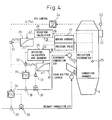
- FIG. 4 is a system diagram of control of combustion of combustible gas according to the present embodiment.
- An exhaust gas oxygen sensor 23 for detecting the oxygen concentration in the exhaust gas is arranged at an exhaust gas outlet 22 of the combustion chamber 9.
- a detection signal of the oxygen concentration of the exhaust gas oxygen sensor 23 is sent to the exhaust gas oxygen concentration control meter 24.
- the combustion chamber 9 is provided with a temperature detection sensor 25 comprised of a photosensor measuring the conditions in the furnace.
- the signal of the temperature detection sensor 25 is sent to a rate calculator 26 and moving average calculator 27.
- a rate calculator 28 calculates the amount of change of the combustion load from the steady state from the output of the temperature detection sensor 25 and the output of the moving average calculator 27 and inputs it to a combustion load correction table 29.
- the combustion load correction table 29 calculates the necessary amount of air for the amount of change of the combustion load and outputs the corrected amount of air.
- the primary and secondary air flow rate control meters 34,37 receive as input the measured signals of the flow rates from the primary and secondary air flow meters 35,38 and input an air amount instruction from the exhaust gas oxygen concentration control meter 24 and an output value of the combustion load correction table 29 to an adder 31.
- the signal of the adder 31 is input to the primary and secondary air flow rate control meters 34, 37, whereby the primary and secondary air flow control valves 36, 39 are adjusted so that suitable amounts of air are blown into the furnace.
- the secondary air flow rate control meter 37 receives as input the measured signal of the flow rate from the secondary air flow meter 38.
- the signal of the rate calculator 6 is input into the combustion load correction table 30.
- the combustion load correction table 30 calculates the amount of change of the combustion load detected as the temperature change based on the input rate of change of the temperature, outputs the necessary amount of air as the valve opening degree, and inputs it to the secondary air flow control valve 37.
- the signal of the secondary air flow rate control meter 37 is input together with the signal of the combustion load correction table 30 to the adder 33.
- the signal of the adder 33 is sent to the secondary air flow control valve 39 and regulates the opening degree of the secondary air flow control valve 39.
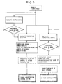
- FIG. 5 is a flow diagram of the control of combustion of the combustible gas according to an example of the present invention.
- the rate calculator 8 calculates the amount of change of the temperature from the output of the temperature detection sensor 25 and the moving average calculator 27 and outputs the result of calculation as a correction value ⁇ MV of the amount of air so as to cancel out the amount of change of the combustion load at the combustion load correction table 29.
- the correction value is added as a correction amount to the oxygen concentration control system.
- the correction amount ⁇ MV is output from the output value MV of the control system at the normal oxygen concentration as MV+ ⁇ MV to the combustion air control system as the amount of air required.
- the oxygen concentration control system continues control continuously using the PV detected as the result of the amount of air controlled as MV+ ⁇ MV.
- step corrective control when the result of calculation at the rate calculator 26 from the output of the temperature detection sensor 25 is that the rate of change does not exceed the prescribed value, the secondary air flow control valve 39 is set to the ordinary opening degree MV so as to obtain the normal secondary air flow rate SV.
- the prescribed value of the rate of change of temperature is set to 10°C to 30°C.
- the rate of change exceeds the prescribed value, it is judged that the char has suddenly been burned and the amount of combustion air is increased so that the secondary air flow control valve 39 changes from the normal opening degree MV to MV+ ⁇ MV.
- the load in the combustion chamber is increasing, so the air required for the initial combustion is provided by the amount of excess air of the secondary combustion air.
- the amount of air increased in the above decision is made to catch up until this air becomes insufficient.
- the increase in the amount of combustion air is held for a time commensurate with the delay time of the exhaust gas oxygen concentration control meter.
- the secondary air flow rate catches up by the correction by the exhaust gas oxygen concentration control meter.
- the moving average is smaller than the prescribed value, no correction is applied, the change is judged to be a normal rise in temperature such as in the process of reset from the low load state, and a drop in temperature due to excess air is prevented.
- the prescribed value is set to 800°C to 1000°C or so.
- the result of detection of a temperature change due to a momentary fluctuation of the furnace pressure is recognized as a change unrelated to the combustion load and no correction is made, so destabilization of control is prevented.
- the combustion control of the present embodiment detects a change in the furnace temperature as light and controls the oxygen concentration and corrects the secondary air flow rate using the temperature change as a feed forward element of the secondary air flow rate, so the ability to track rapid combustion is good. Further, the amount of temperature change can be grasped as the amount of combustion load and the absolute amount of the amount of air correction can be determined with respect to the absolute amount of temperature change, so high precision combustion control becomes possible. Further, by continuously making the correction, it is possible to give a suitable amount of correction even with respect to the time-integrated value of the amount of change difficult to correct in the past.
- the present combustion control temperature control of the combustion chamber at a higher temperature becomes possible, the combustion chamber temperature is held at a higher temperature than the past, and the combustible gas and combustible dust are burned at a high temperature, so the unburned matter can easily be completely burned and operation can be continued without problem even at 900°C to 1000°C.
- the high temperature temperature-control of the combustion chamber there is also the secondary effect that clinker becomes hard to stick to the furnace walls.
- the present invention can use the air in the waste disposal apparatus as the combustion air to be blown into the combustion chamber.
- the burner of the combustion chamber is placed facing slightly downward.
- the furnace wall in front of the burner (position somewhat lower than the burner) becomes locally high in temperature and clinker may be produced. Therefore, at these parts, a support gas comprised of combustion exhaust gas of a low oxygen concentration (for example, the flue exhaust gas after IDF) is used for combustion so as to cause slow combustion and suppress any sudden rise in temperature and thereby prevent production of clinker.
- a support gas comprised of combustion exhaust gas of a low oxygen concentration (for example, the flue exhaust gas after IDF) is used for combustion so as to cause slow combustion and suppress any sudden rise in temperature and thereby prevent production of clinker.
- the combustion air blown into the combustion chamber for example, either the ejected gas produced at the tap hole of the waste melting furnace at the time of tapping or the air of the waste storage chamber storing the general waste or industrial waste or mixed air of the same may be used. If using the ejected gas or the air of the waste storage chamber storing municipal waste or industrial waste or mixed air of the same
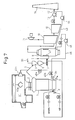
- FIG. 7 shows an example of a waste melting apparatus using the method of the present invention.
- the waste melting furnace 1 is charged with waste from the waste storage chamber 41 by a bucket 41a by the charging apparatus 2 of the double seal valve mechanism of the top of the furnace and is charged with secondary materials including the coke and the limestone by the charging apparatus 2.
- the waste is dried, broken down by heat, burned, and melted, then discharged from the tap hole 3 as a melted material.
- the combustible matter is discharged from the gas pipe 4 at the top of the waste melting furnace as heat decomposed gas, while the combustible dust is trapped by a cyclone or other dust collecting apparatus 5 and stored in the combustible dust storage tank 6, fed out by the combustible dust feedout apparatus 7, and blown from the blast tuyere 8 supplying oxygen-enriched air to the furnace.
- the exhaust gas from the dust collecting apparatus 5 is burned in the combustion chamber 9, its heat is recovered by the boiler 10, and the produced steam is sent to a steam turbine power generation apparatus 11.
- the exhaust gas of the boiler 10 is separated into solids and gases by the dust collecting apparatus 12, then is discharged from the exhaust flue 14 by the blower 13.
- the flue 42 and the combustion chamber 9 are connected by a pipe 43 via a blower 44, so the flue exhaust gas can be sent as combustion air to the combustion chamber 9.
- combustion air comprised of low oxygen concentration flue exhaust gas (oxygen concentration of 8 to 12% or so and temperature of about 150°C)
- oxygen concentration of 8 to 12% or so and temperature of about 150°C oxygen concentration of 8 to 12% or so and temperature of about 150°C
- a hood 3a to cover the tap hole 3, collect the ejected gas including the dust and smoke by the hood 3a, and send it to the combustion chamber 9 through the blower 45 by a pipe 46 as combustion air.
- the air and ejected gas of the waste storage chamber 41 can be switched or mixed by operating the valves 46a, 46b.
- FIG. 8(a) is a schematic cross-sectional view of a combustion chamber provided with boiler type walls of the present invention, while (b) is a cross-sectional view along the A-A of (a).
- at least part of the furnace walls of the combustion chamber 9 can be made of boiler type furnace walls 47 comprised of low temperature metal walls or caster covering the metal walls.
- the combustion chamber 9 by the boiler type furnace walls 47, it is possible to prevent trouble such as melting of the clinker. That is, the surfaces of the boiler walls are low in temperature, so the melted ash is immediately cooled and peels off from the walls. The peeled off ash is discharged from the bottom of the combustion chamber 9. Further, by cooling the combustion exhaust gas, it is possible to burn it without blowing in excess air gas.
- the downstream boiler or dust collecting apparatus (bag filter and the like), induction blower, and the like can be made compact.
- the chamber is comprised of boiler type walls 47 1 meter above and below the burner 48, so melting of the ash can be reduced more.
- FIG. 9 shows the arrangement and structure of the burner used in the present invention, where (a) is a cross-sectional schematic view along B-B of FIG. 8(a) and (b) is the cross-sectional schematic view along C-C of (a) showing the slits.
- the combustible gas after dust removal is sent to the combustion chamber 9 via the duct 51.
- the front end of the duct 51 is connected to the combustible gas slits 50 of the burner 48 provided with the vertically long slits 49,50.
- This burner 48 is connected to the combustion chamber 9.
- the combustible gas after dust removal is blown into the combustion chamber from the slits 50.
- FIG. 9 shows the arrangement and structure of the burner used in the present invention, where (a) is a cross-sectional schematic view along B-B of FIG. 8(a) and (b) is the cross-sectional schematic view along C-C of (a) showing the slits.
- the slits 49, 50 of the burner 48 are arranged so that the combustible gas swirls along the combustion chamber walls. Further, the slits 49, 50 of the burner 48 are comprised of the slits 49 blowing in combustion air and slits 50 blowing in combustible gas alternately arranged.
- the burner 48 when using the burner 48 provided with the alternately arranged vertically long slits 49, 50 to introduce combustible gas into the combustion chamber 9 and blow in air, it is preferable to adjust the flow rates of the combustion air and combustible gas in the slits.
- the structure of the combustion burner for burning the combustible gas in the combustion chamber 9 becomes important.
- a good exhaust gas composition can be obtained.
- the present invention reduces the concentration of dust in combustible gas to 0.02 to 0.07 kg/Nm 3 in range to enable the combustible gas produced in a waste disposal furnace to be treated without incurring a high equipment cost and can satisfy the controls of flue dioxins (0.01 ng-TEQ/Nm 3 ) and prevent trouble such as deposition and blockage of a heat exchanger.
- the apparatus for treatment of the present invention can satisfy the controls of flue dioxins and prevent trouble such as deposition and blockage of a heat exchanger without using a dust collecting apparatus having a high dust collection efficiency.
Applications Claiming Priority (2)
| Application Number | Priority Date | Filing Date | Title |
|---|---|---|---|
| JP2004343005A JP4542417B2 (ja) | 2004-11-26 | 2004-11-26 | 廃棄物溶融炉の可燃性ガスの処理方法 |
| PCT/JP2005/002505 WO2006057075A1 (ja) | 2004-11-26 | 2005-02-10 | 廃棄物溶融炉の可燃性ガスの処理方法及び処理装置 |
Publications (4)
| Publication Number | Publication Date |
|---|---|
| EP1816396A1 true EP1816396A1 (de) | 2007-08-08 |
| EP1816396A4 EP1816396A4 (de) | 2012-03-21 |
| EP1816396B1 EP1816396B1 (de) | 2013-12-04 |
| EP1816396B8 EP1816396B8 (de) | 2014-02-12 |
Family
ID=36497822
Family Applications (1)
| Application Number | Title | Priority Date | Filing Date |
|---|---|---|---|
| EP05710353.3A Expired - Fee Related EP1816396B8 (de) | 2004-11-26 | 2005-02-10 | Behandlungsverfahren für brennbares gas in abfallschmelzofen |
Country Status (6)
| Country | Link |
|---|---|
| EP (1) | EP1816396B8 (de) |
| JP (1) | JP4542417B2 (de) |
| KR (1) | KR100852507B1 (de) |
| CN (1) | CN101065613A (de) |
| ES (1) | ES2442384T3 (de) |
| WO (1) | WO2006057075A1 (de) |
Cited By (1)
| Publication number | Priority date | Publication date | Assignee | Title |
|---|---|---|---|---|
| CN108343982A (zh) * | 2018-02-24 | 2018-07-31 | 徐振克 | 一种生活垃圾焚烧烟气处理系统及工艺 |
Families Citing this family (12)
| Publication number | Priority date | Publication date | Assignee | Title |
|---|---|---|---|---|
| WO2008001747A1 (fr) * | 2006-06-28 | 2008-01-03 | Taiheiyo Cement Corporation | Appareil de calcination du ciment et procédé d'assèchement de déchets organiques extrêmement aqueux |
| KR101044975B1 (ko) * | 2008-12-04 | 2011-06-29 | (주)대우건설 | 연소실의 온도 제어 방법 및 장치 |
| JP5767938B2 (ja) * | 2011-10-19 | 2015-08-26 | 新日鉄住金エンジニアリング株式会社 | 低レベル放射性廃棄物の減容処理方法 |
| JP2013155956A (ja) * | 2012-01-31 | 2013-08-15 | Kobelco Eco-Solutions Co Ltd | 二段燃焼炉および二段燃焼方法 |
| JP6061472B2 (ja) * | 2012-01-31 | 2017-01-18 | 株式会社神鋼環境ソリューション | 二段燃焼炉および二段燃焼方法 |
| JP2013155955A (ja) * | 2012-01-31 | 2013-08-15 | Kobelco Eco-Solutions Co Ltd | 二段燃焼炉および二段燃焼方法 |
| JP5120823B1 (ja) * | 2012-02-28 | 2013-01-16 | 新日鉄住金エンジニアリング株式会社 | 廃棄物ガス化溶融炉 |
| JP6070323B2 (ja) | 2013-03-21 | 2017-02-01 | 大陽日酸株式会社 | 燃焼バーナ、バーナ装置、及び原料粉体加熱方法 |
| CN104569038A (zh) * | 2013-10-11 | 2015-04-29 | 上海锦宜仪器有限公司 | 一种用于可燃气体检测装置及方法 |
| JP7016292B2 (ja) * | 2018-06-07 | 2022-02-04 | 日鉄エンジニアリング株式会社 | 二次燃焼炉及びその運転方法 |
| KR102482845B1 (ko) | 2021-02-03 | 2022-12-28 | 한국수력원자력 주식회사 | 유리화설비의 용융물 배출장치 |
| CN117232669B (zh) * | 2023-10-24 | 2024-01-30 | 常州宏川石化仓储有限公司 | 一种温度传感器组件、焚烧系统及废气处理方法 |
Citations (2)
| Publication number | Priority date | Publication date | Assignee | Title |
|---|---|---|---|---|
| EP0999412A1 (de) * | 1997-03-13 | 2000-05-10 | Hitachi Zosen Corporation | Verbrennungsvorrichtung |
| EP1284389A1 (de) * | 2000-05-24 | 2003-02-19 | Nkk Corporation | Müllbehandlungsverfahren und vorrichtung |
Family Cites Families (23)
| Publication number | Priority date | Publication date | Assignee | Title |
|---|---|---|---|---|
| JPS57151503A (en) * | 1981-03-10 | 1982-09-18 | Ishikawajima Harima Heavy Ind | Device for preventing diffusion of malodor of dust pit |
| JPH03170715A (ja) * | 1989-11-30 | 1991-07-24 | Ishikawajima Harima Heavy Ind Co Ltd | 流動床式焼却炉の燃焼制御方法およびその装置 |
| JP2629117B2 (ja) * | 1992-06-11 | 1997-07-09 | 新日本製鐵株式会社 | 廃棄物の溶融炉 |
| JP2937737B2 (ja) * | 1994-03-02 | 1999-08-23 | 川崎重工業株式会社 | 部分燃焼を伴う流動層燃焼方法及び装置 |
| JPH08121728A (ja) * | 1994-10-27 | 1996-05-17 | Nippon Steel Corp | 廃棄物の溶融炉からの発生ガスの燃焼方法および廃棄物溶融炉の2次燃焼炉 |
| JPH08285250A (ja) * | 1995-04-13 | 1996-11-01 | Nippon Steel Corp | 廃棄物溶融炉の可燃性ダストの処理方法 |
| JPH10265780A (ja) * | 1997-03-26 | 1998-10-06 | Hiroshi Shimizu | 可燃廃棄物の連続ガス化処理装置 |
| JPH11125414A (ja) * | 1997-10-23 | 1999-05-11 | Nippon Steel Corp | 廃棄物溶融炉の燃焼室燃焼制御方法 |
| JP4039647B2 (ja) * | 1997-12-02 | 2008-01-30 | 新日鉄エンジニアリング株式会社 | 廃棄物溶融炉におけるダストの処理方法及びその装置 |
| JP3306849B2 (ja) * | 1998-07-24 | 2002-07-24 | 日本碍子株式会社 | 廃棄物焼却方法 |
| JP2000161622A (ja) * | 1998-12-01 | 2000-06-16 | Nkk Corp | 廃棄物の処理方法及び装置 |
| JP3683146B2 (ja) * | 1999-12-21 | 2005-08-17 | 株式会社クボタ | ゴミ焼却炉及びその運転方法 |
| JP4420155B2 (ja) * | 2000-05-25 | 2010-02-24 | Jfeエンジニアリング株式会社 | 廃棄物からの熱回収方法及び装置 |
| JP2002013715A (ja) * | 2000-06-28 | 2002-01-18 | Nkk Corp | 廃棄物焼却炉 |
| JP2002317914A (ja) * | 2001-04-23 | 2002-10-31 | Nkk Corp | 溶融炉の排ガス処理方法及びその設備 |
| JP3944389B2 (ja) * | 2001-12-12 | 2007-07-11 | 株式会社神鋼環境ソリューション | 熱分解ガス化溶融炉における燃焼空気量制御システム |
| JP2003247711A (ja) * | 2002-02-25 | 2003-09-05 | Ishikawajima Harima Heavy Ind Co Ltd | 焼却炉の燃焼抑制装置 |
| JP2004108657A (ja) * | 2002-09-18 | 2004-04-08 | Tsukishima Kikai Co Ltd | 高温排ガスの処理方法および処理装置 |
| JP3896062B2 (ja) * | 2002-10-15 | 2007-03-22 | 新日鉄エンジニアリング株式会社 | 廃棄物溶融炉への可燃性ダスト吹き込み方法 |
| JP2004232881A (ja) * | 2003-01-28 | 2004-08-19 | Kubota Corp | 焼却処理設備 |
| JP2004271039A (ja) * | 2003-03-07 | 2004-09-30 | Babcock Hitachi Kk | 熱分解ガス化溶融システム |
| JP4004476B2 (ja) * | 2003-03-11 | 2007-11-07 | 財団法人北九州産業学術推進機構 | 焼却炉及び焼却炉内清掃・補修方法 |
| JP4064269B2 (ja) * | 2003-03-13 | 2008-03-19 | 新日鉄エンジニアリング株式会社 | 廃棄物溶融炉の燃焼室における燃焼制御方法 |
-
2004
- 2004-11-26 JP JP2004343005A patent/JP4542417B2/ja active Active
-
2005
- 2005-02-10 KR KR1020077010831A patent/KR100852507B1/ko active IP Right Grant
- 2005-02-10 WO PCT/JP2005/002505 patent/WO2006057075A1/ja active Application Filing
- 2005-02-10 ES ES05710353.3T patent/ES2442384T3/es active Active
- 2005-02-10 EP EP05710353.3A patent/EP1816396B8/de not_active Expired - Fee Related
- 2005-02-10 CN CNA2005800404540A patent/CN101065613A/zh active Pending
Patent Citations (2)
| Publication number | Priority date | Publication date | Assignee | Title |
|---|---|---|---|---|
| EP0999412A1 (de) * | 1997-03-13 | 2000-05-10 | Hitachi Zosen Corporation | Verbrennungsvorrichtung |
| EP1284389A1 (de) * | 2000-05-24 | 2003-02-19 | Nkk Corporation | Müllbehandlungsverfahren und vorrichtung |
Non-Patent Citations (1)
| Title |
|---|
| See also references of WO2006057075A1 * |
Cited By (1)
| Publication number | Priority date | Publication date | Assignee | Title |
|---|---|---|---|---|
| CN108343982A (zh) * | 2018-02-24 | 2018-07-31 | 徐振克 | 一种生活垃圾焚烧烟气处理系统及工艺 |
Also Published As
| Publication number | Publication date |
|---|---|
| EP1816396A4 (de) | 2012-03-21 |
| JP2006153339A (ja) | 2006-06-15 |
| KR20070063594A (ko) | 2007-06-19 |
| WO2006057075A1 (ja) | 2006-06-01 |
| EP1816396B1 (de) | 2013-12-04 |
| ES2442384T3 (es) | 2014-02-11 |
| JP4542417B2 (ja) | 2010-09-15 |
| KR100852507B1 (ko) | 2008-08-18 |
| EP1816396B8 (de) | 2014-02-12 |
| CN101065613A (zh) | 2007-10-31 |
Similar Documents
| Publication | Publication Date | Title |
|---|---|---|
| EP1816396B1 (de) | Behandlungsverfahren für brennbares gas in abfallschmelzofen | |
| EP1148295B1 (de) | Abfallvergasungsschmelzofen und vergasungsschmelzverfahren | |
| WO2002021047A1 (fr) | Four de fusion a gazeification de dechets et procede de fonctionnement de ce four de fusion | |
| JP4829817B2 (ja) | 廃棄物の焼却装置及び焼却方法 | |
| CN112240553B (zh) | 一种等离子体气化熔融炉系统及其控制方法 | |
| JP5611418B2 (ja) | ガス化溶融システムの燃焼制御方法及び該システム | |
| WO2008038492A1 (fr) | PROCÉDÉ DE FONCTIONNEMENT ET APPAREIL DE COMMANDE DE FONCTIONNEMENT POUR UN FOUR à FUSION DE GAZÉIFICATION | |
| JP4918834B2 (ja) | 廃棄物溶融炉および廃棄物溶融炉の操業方法 | |
| JP4126317B2 (ja) | ガス化溶融システムの運転制御方法及び該システム | |
| JP3027694B2 (ja) | 廃棄物溶融炉の燃焼制御方法 | |
| JP4111107B2 (ja) | 溶融炉二次燃焼室ダスト排出機の腐食防止方法及び装置 | |
| JP5472847B2 (ja) | 廃棄物溶融炉設備の蒸気量制御装置 | |
| JP3902454B2 (ja) | 燃焼制御方法及び廃棄物処理装置 | |
| JP4108624B2 (ja) | 燃焼制御方法および廃棄物処理装置 | |
| JPH08121728A (ja) | 廃棄物の溶融炉からの発生ガスの燃焼方法および廃棄物溶融炉の2次燃焼炉 | |
| JP4377826B2 (ja) | 廃棄物溶融処理方法 | |
| JP3869669B2 (ja) | コークス乾式消火方法及び装置 | |
| JP3621792B2 (ja) | 廃棄物溶融炉生成ガス燃焼炉の燃焼制御方法 | |
| JP5021543B2 (ja) | 燃焼制御方法、及び廃棄物処理装置 | |
| WO2008029712A1 (fr) | Incinérateur à distributeur automatique et procédé pour réguler la combustion dans l'incinérateur | |
| JP2007046121A (ja) | 自熔製錬炉の操業方法 | |
| JP4233212B2 (ja) | 高温旋回燃焼方法及び廃棄物処理装置 | |
| JPH08121727A (ja) | 廃棄物の溶融炉の2次燃焼炉構造 | |
| JP4283254B2 (ja) | ガス化溶融システムの運転制御方法及び装置 | |
| JP2001090928A (ja) | 廃棄物溶融炉の操業方法 |
Legal Events
| Date | Code | Title | Description |
|---|---|---|---|
| PUAI | Public reference made under article 153(3) epc to a published international application that has entered the european phase |
Free format text: ORIGINAL CODE: 0009012 |
|
| 17P | Request for examination filed |
Effective date: 20070531 |
|
| AK | Designated contracting states |
Kind code of ref document: A1 Designated state(s): ES FR GB IT |
|
| RBV | Designated contracting states (corrected) |
Designated state(s): ES FR GB IT |
|
| DAX | Request for extension of the european patent (deleted) | ||
| A4 | Supplementary search report drawn up and despatched |
Effective date: 20120220 |
|
| RIC1 | Information provided on ipc code assigned before grant |
Ipc: F23G 5/50 20060101ALI20120214BHEP Ipc: F23G 5/32 20060101ALI20120214BHEP Ipc: F23G 5/00 20060101AFI20120214BHEP Ipc: F23G 5/16 20060101ALI20120214BHEP Ipc: F23G 5/46 20060101ALI20120214BHEP Ipc: F23J 15/02 20060101ALI20120214BHEP Ipc: F23L 7/00 20060101ALI20120214BHEP |
|
| 17Q | First examination report despatched |
Effective date: 20130128 |
|
| GRAP | Despatch of communication of intention to grant a patent |
Free format text: ORIGINAL CODE: EPIDOSNIGR1 |
|
| INTG | Intention to grant announced |
Effective date: 20130612 |
|
| GRAS | Grant fee paid |
Free format text: ORIGINAL CODE: EPIDOSNIGR3 |
|
| GRAA | (expected) grant |
Free format text: ORIGINAL CODE: 0009210 |
|
| AK | Designated contracting states |
Kind code of ref document: B1 Designated state(s): ES FR GB IT |
|
| REG | Reference to a national code |
Ref country code: GB Ref legal event code: FG4D |
|
| RAP2 | Party data changed (patent owner data changed or rights of a patent transferred) |
Owner name: NIPPON STEEL & SUMIKIN ENGINEERING CO., LTD. |
|
| REG | Reference to a national code |
Ref country code: ES Ref legal event code: FG2A Ref document number: 2442384 Country of ref document: ES Kind code of ref document: T3 Effective date: 20140211 |
|
| PLBE | No opposition filed within time limit |
Free format text: ORIGINAL CODE: 0009261 |
|
| STAA | Information on the status of an ep patent application or granted ep patent |
Free format text: STATUS: NO OPPOSITION FILED WITHIN TIME LIMIT |
|
| 26N | No opposition filed |
Effective date: 20140905 |
|
| REG | Reference to a national code |
Ref country code: FR Ref legal event code: PLFP Year of fee payment: 12 |
|
| REG | Reference to a national code |
Ref country code: FR Ref legal event code: PLFP Year of fee payment: 13 |
|
| REG | Reference to a national code |
Ref country code: FR Ref legal event code: PLFP Year of fee payment: 14 |
|
| PGFP | Annual fee paid to national office [announced via postgrant information from national office to epo] |
Ref country code: FR Payment date: 20210113 Year of fee payment: 17 Ref country code: IT Payment date: 20210112 Year of fee payment: 17 |
|
| PGFP | Annual fee paid to national office [announced via postgrant information from national office to epo] |
Ref country code: GB Payment date: 20210203 Year of fee payment: 17 Ref country code: ES Payment date: 20210308 Year of fee payment: 17 |
|
| GBPC | Gb: european patent ceased through non-payment of renewal fee |
Effective date: 20220210 |
|
| PG25 | Lapsed in a contracting state [announced via postgrant information from national office to epo] |
Ref country code: FR Free format text: LAPSE BECAUSE OF NON-PAYMENT OF DUE FEES Effective date: 20220228 |
|
| PG25 | Lapsed in a contracting state [announced via postgrant information from national office to epo] |
Ref country code: GB Free format text: LAPSE BECAUSE OF NON-PAYMENT OF DUE FEES Effective date: 20220210 |
|
| REG | Reference to a national code |
Ref country code: ES Ref legal event code: FD2A Effective date: 20230327 |
|
| PG25 | Lapsed in a contracting state [announced via postgrant information from national office to epo] |
Ref country code: ES Free format text: LAPSE BECAUSE OF NON-PAYMENT OF DUE FEES Effective date: 20220211 |
|
| PG25 | Lapsed in a contracting state [announced via postgrant information from national office to epo] |
Ref country code: IT Free format text: LAPSE BECAUSE OF NON-PAYMENT OF DUE FEES Effective date: 20220210 |