EP1800398B1 - Unified analog input front end apparatus and method - Google Patents
Unified analog input front end apparatus and method Download PDFInfo
- Publication number
- EP1800398B1 EP1800398B1 EP05816029A EP05816029A EP1800398B1 EP 1800398 B1 EP1800398 B1 EP 1800398B1 EP 05816029 A EP05816029 A EP 05816029A EP 05816029 A EP05816029 A EP 05816029A EP 1800398 B1 EP1800398 B1 EP 1800398B1
- Authority
- EP
- European Patent Office
- Prior art keywords
- gain
- resistor
- error
- switch
- input
- Prior art date
- Legal status (The legal status is an assumption and is not a legal conclusion. Google has not performed a legal analysis and makes no representation as to the accuracy of the status listed.)
- Expired - Lifetime
Links
Images


Classifications
-
- H—ELECTRICITY
- H03—ELECTRONIC CIRCUITRY
- H03F—AMPLIFIERS
- H03F1/00—Details of amplifiers with only discharge tubes, only semiconductor devices or only unspecified devices as amplifying elements
- H03F1/34—Negative-feedback-circuit arrangements with or without positive feedback
-
- H—ELECTRICITY
- H03—ELECTRONIC CIRCUITRY
- H03M—CODING; DECODING; CODE CONVERSION IN GENERAL
- H03M1/00—Analogue/digital conversion; Digital/analogue conversion
- H03M1/12—Analogue/digital converters
-
- H—ELECTRICITY
- H03—ELECTRONIC CIRCUITRY
- H03F—AMPLIFIERS
- H03F3/00—Amplifiers with only discharge tubes or only semiconductor devices as amplifying elements
- H03F3/45—Differential amplifiers
- H03F3/45071—Differential amplifiers with semiconductor devices only
- H03F3/45076—Differential amplifiers with semiconductor devices only characterised by the way of implementation of the active amplifying circuit in the differential amplifier
- H03F3/45475—Differential amplifiers with semiconductor devices only characterised by the way of implementation of the active amplifying circuit in the differential amplifier using IC blocks as the active amplifying circuit
-
- H—ELECTRICITY
- H03—ELECTRONIC CIRCUITRY
- H03G—CONTROL OF AMPLIFICATION
- H03G1/00—Details of arrangements for controlling amplification
- H03G1/0005—Circuits characterised by the type of controlling devices operated by a controlling current or voltage signal
- H03G1/0088—Circuits characterised by the type of controlling devices operated by a controlling current or voltage signal using discontinuously variable devices, e.g. switch-operated
-
- H—ELECTRICITY
- H03—ELECTRONIC CIRCUITRY
- H03M—CODING; DECODING; CODE CONVERSION IN GENERAL
- H03M1/00—Analogue/digital conversion; Digital/analogue conversion
- H03M1/12—Analogue/digital converters
- H03M1/124—Sampling or signal conditioning arrangements specially adapted for A/D converters
- H03M1/129—Means for adapting the input signal to the range the converter can handle, e.g. limiting, pre-scaling ; Out-of-range indication
-
- H—ELECTRICITY
- H03—ELECTRONIC CIRCUITRY
- H03F—AMPLIFIERS
- H03F2203/00—Indexing scheme relating to amplifiers with only discharge tubes or only semiconductor devices as amplifying elements covered by H03F3/00
- H03F2203/45—Indexing scheme relating to differential amplifiers
- H03F2203/45138—Two or more differential amplifiers in IC-block form are combined, e.g. measuring amplifiers
-
- H—ELECTRICITY
- H03—ELECTRONIC CIRCUITRY
- H03F—AMPLIFIERS
- H03F2203/00—Indexing scheme relating to amplifiers with only discharge tubes or only semiconductor devices as amplifying elements covered by H03F3/00
- H03F2203/45—Indexing scheme relating to differential amplifiers
- H03F2203/45572—Indexing scheme relating to differential amplifiers the IC comprising one or more Zener diodes to the input leads
-
- H—ELECTRICITY
- H03—ELECTRONIC CIRCUITRY
- H03F—AMPLIFIERS
- H03F2203/00—Indexing scheme relating to amplifiers with only discharge tubes or only semiconductor devices as amplifying elements covered by H03F3/00
- H03F2203/45—Indexing scheme relating to differential amplifiers
- H03F2203/45616—Indexing scheme relating to differential amplifiers the IC comprising more than one switch, which are not cross coupled
Definitions
- the present invention relates generally to the front end systems.
- the present invention relates to a unified analog input front end apparatus and method.
- a programmable variable gain amplifier in front of an analog to digital converter comprising an automatic gain control is know from US 2003/0215033 A1 .
- the analog input front end includes a configurable gain stage and an analog-to-digital converter.
- the configurable gain stage receives an analog input signal, such as a differential analog input signal, and provides a gain value to the analog input signal so as to output a gain-adjusted analog signal within a particular voltage range compatible with the input range of the Analog to Digital Converter.
- the analog-to-digital converter receives the gain-adjusted analog input signal and performs analog-to-digital conversion on the gain-adjusted analog input signal, so as to output a digital signal that is indicative of the analog input signal.
- Another aspect of the invention relates to a method of converting an analog input signal to a digital signal, which includes receiving, by a configurable gain stage, the analog input signal.
- the method also includes providing, by the configurable gain stage, a gain value to the analog input signal so as to output a gain-adjusted analog input signal that is within a particular voltage range between a maximum and a minimum value.
- the method further includes receiving, by an analog-to-digital converter, the gain-adjusted analog input signal output from the configurable gain stage.
- the method still further includes performing, by the analog-to-digital converter, analog-to-digital conversion on the gain-adjusted analog input signal, so as to output a digital signal that is indicative of the analog input signal.
- a configurable gain stage which includes a positive differential input signal stage that includes a first resistor having a first resistance value, a second resistor having a second resistance value, and a first operational amplifier.
- the configurable gain stage also includes a negative differential input signal stage that includes a third resistor having the first resistance value, a fourth resistor having the second resistance value, and a second operational amplifier.
- the configurable gain stage further includes first through sixth switches, the first and second switches being provided on the positive differential input signal stage, the third and fourth switches being provided on the negative differential input signal stage, the fifth switch being provided between the positive and negative differential input signal stages, and the sixth switch being provided between a ground potential and at least one of the positive and negative differential input signal stages.
- the configurable gain stage is capable of operating in a first mode of operation providing a gain value greater than unity to an input differential signal pair, a second mode of operation providing a unity gain value to the input differential signal pair, and a third mode of operation provide a gain value greater than zero but less than unity to the input differential signal pair
- the calibration circuit includes an operational amplifier, a digital-to-analog converter, a resistor ladder provided between the operational amplifier and the digital-to-analog converter, a voltage reference unit connected to the digital-to-analog converter and a plurality of switches that provide an on/off connection to the gain stage and the analog-to-digital converter unit.
- the calibration circuit is configured to maintain a total error of the gain stage and the analog-to-digital converter unit to be less than a predetermined value, for all operating modes of the gain stag e and the analog-to-digital converter.
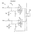
- Figure 1 is a circuit level diagram illustrating an overall topology of a unified analog input front end according to a first embodiment of the invention
- Figure 2 is a circuit level diagram illustrating the configurable gain stage portion of the unified analog input front end, with actual resistance values and capacitance values provided in a preferred configuration of the first embodiment
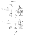
- Figure 3 is a circuit level diagram illustrating the configurable gain stage operating in attenuation mode
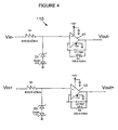
- Figure 4 is a circuit level diagram illustrating the configurable gain stage operating in unity gain mode
- Figure 5 is a circuit level diagram illustrating the configurable gain stage operating in positive gain mode
- Figure 6 is a block diagram illustrating an analog-to-digital converter that can be utilized according to a preferred configuration of the first embodiment
- Figure 7 is a block diagram illustrating the error effects on the system according to the first embodiment
- Figure 8 is a block diagram illustrating a calibration unit coupled to a unified analog input front end, according to a second embodiment of the invention.
- Figure 9 is a circuit level diagram illustrating the calibration unit according to a preferred configuration of the second embodiment.
- the unified analog input front end is a high-performance yet very general purpose analog signal processing and conversion circuit for data acquisition. It is configurable in real-time by way of digital commands which can set the unified analog input front end to perform analog-to-digital (A-to-D) conversion on input signals, such as differential signals, in a plurality of full-scale ranges.
- A-to-D analog-to-digital
- other full-scale ranges may be possible for a unified analog input front end made in accordance with the present invention.
- the unified analog input front end is capable of performing signal processing and conversion for analog input signals from D.C. up to a predetermined frequency.
- the predetermined frequency is 500 Hz, but of course it may be set to any desired frequency to suit a particular purpose, as known to one of ordinary skill in the art (e.g., a value between 50 Hz and 10 kHz).
- the unified analog input front is designed to have a 14 bit resolution and an accuracy of better than 1 % full scale. This is accomplished with a carefully developed and very flexible topology and by the use of custom designed components, such as ones manufactured by Maxim Integrated Products, Inc., and by Alpha, Inc.
- the unified analog input front end 100 includes a configurable gain stage 110 constructed of discrete components, and an analog-to-digital converter 120.
- the analog-to-digital converter 120 is a Max1338 A/D converter manufactured by Maxim Integrated Products, Inc., but one of ordinary skill in the art will recognize that other types of converters may be utilized for the analog-to-digital converter 120 portion of the unified analog input front end 100, while remaining within the scope of the invention.
- the variable full scale range discussed herein is a function of the Max 1338, and other types of A/D converters that may be utilized with a unified analog input front end according to an embodiment of the present invention may or may not have such a feature.
- the configurable gain stage 110 includes a first resistor R1 with a resistance value of 1 9R (R being a predetermined value), a second resistor R2 with a resistance value of R, a third resistor R3 with a resistance value of 7R, a first capacitor C1 with a capacitance value of C, a first Zener diode D1, a first operational amplifier U1, a fourth resistor R4 with a resistance value of 19R, a fifth resistor R5 with a resistance value of R, a sixth resistor R6 with a resistance value of 7R, a second capacitor C2 with a capacitance value of C, a second Zener diode D2, and a second operational amplifier U2.
- a first switch S1 is included in the unified analog input front end 100.
- a second switch S2 is also included in the unified analog input front end 100.
- a positive differential input signal (of a differential input signal pair) is input to the first resistor R1
- a negative differential input signal (of the differential input signal pair) is input to the fourth resistor R4, whereby the unified analog input front end 100 is configured to determine a digital value corresponding to the differential input signal.
- the configurable gain stage 110 serves three basic purposes: a) to attenuate large signals which are beyond the A/D converter's 120 input signal range and that could damage the A/D converter 120, b) to amplify small signals which less than the input signal range of the A/D converter 120, and c) to serve as a high input impedance/low output impedance buffer for signal sources which may be attenuated by the relatively low input impedance (around 15K Ohm) of the A/D converter 120.
- the three different gain configurations of the configurable gain stage 110 are selectable by way of digitally controlled analog switches S1 1 - S6.
- R1 - R3 and R4 - R6 are preferably resistors custom-packaged in threes, such as ones sold by Alpha, Inc. In the preferred embodiment, each of the resistor packs meet a 19:1:32 resistance ratio with 0.02% accuracy.
- OpAmps U1 and U2 are preferably high precision, low bias current, low offset voltage operational amplifiers.
- Capacitors C1 and C2 are 10 pF capacitors in the preferred embodiment, whereby they are included so as to provide some filtering and oscillation protection to the OpAmps U1 and U2, while keeping the high end of the low-pass filter they create well above a predetermined frequency range.
- the predetermined frequency range (for signals input to the unified analog input front end 100) is D.C. (0 Hz) to 500 Hz, which is the range of signals the unified analog input front end 100 is designed to measure.
- Zener Diodes D1 and D2 are used to protect the OpAmps U1 and U2 and the switches S1 - S6 from voltages beyond their rails, whereby the Zener Diodes D1 and D2 are configured as back-to-back diodes (for bipolar signals).
- FIG. 3 illustrates the topology of the configurable gain stage 110 when switched to attenuation mode, with a gain of 0.05, whereby actual resistance and capacitance values are shown in a preferred implementation of the configurable gain stage 110.
- This mode of operation is useful when the input voltage range is large, such as a ⁇ 200 V input range, whereby that large input range is collapsed to a ⁇ 10V input range that is suitable for input to an A/D.
- switches S1, S4 and S6 are closed, while all of the other switches (S2, S3 and S5) are open.
- the switches S1 - S6 are represented by 5 ⁇ resistances, to represent the maximum on-resistance of the Maxim Max4665 switches that are used in the preferred implementation of the configurable gain stage 110.
- Gain Error is introduced by the tolerance of the resistors (0.02 % tolerance for the resistors used in the preferred embodiment) and the resistance of the switches (3 - 5 ⁇ for the Max 4665 switches used in the preferred embodiment). From Equation #7, above, it can be seen that Gain Error can occur either as a result of an average error common to both the positive and negative differential legs (in the first term) or mismatched error proportional to the common mode ratio K (in the second term).
- error is proportional to common mode, and becomes a limiting factor of common mode, based upon the percent of the error budget being used by offset in the configurable gain stage 110 and error figures of the A/D converter 120.
- This mode of operation is suitable when the input signal voltage range is in a proper range for input to an A/D, but where a high input impedance/low input impedance buffer is needed.
- the 32.4 k ⁇ resistor R2, R5 are not switched in as either a voltage divider or to create amplification around the operational amplifiers U1 and U2.
- On a ⁇ 1 OV full-scale range of the A/D 120 this would correspond to a 0.05294% error.
- ⁇ 1.25V this would correspond to a 0.424% error.
- Fig ure 5 shows the configurable gain stage 110 operating in the gain mode (gain > 1).
- This mode of operation is useful when the input voltage range is small, such as ⁇ 0.3125 V input range, whereby that small input range is expanded to a ⁇ 2.5V input range that is suitable for input to the A/D 120.
- the negative side of the differential is coupled to Vi N- , and the voltage is buffered through operational amplifier U1 with no gain.
- Switch S3 is closed, so that the low side of resistor R5 is attached to V out-.
- operational amplifier U2 and resistors R5 and R6 act as a basic non-inverting amplifier. Instead of being referenced to ground, this amplifier is referenced to V out- , which is equal to V IN- .
- Analog-to-Digital Converter 120 which forms part of the unified analog input front end 100.
- the Analog-to-Digital Converter 120 corresponds to an ACGO 4-Channel, 14-bit differential A-D converter in the preferred embodiment, but one of ordinary skill in the art will recognize that any type or model of A-D converter may be utilized, while remaining within the spirit and scope of the present invention.
- Figure 6 shows details of the ACGO A-D Converter 120.
- a track-and-hold circuit 610 allows all four channels to be sampled simultaneously and converted in sequence by a single block of conversion circuitry.
- a range selection circuit 620 which is implemented as a programmable gate array in the preferred embodiment, allows the A-D converter 120 to be configured for a plurality of different ranges on a channel-by-channel basis by way of digital commands (signals DO, D1) input to the A-D Converter 120.
- the different ranges correspond to: ⁇ 10V, ⁇ 5V, ⁇ 2.5V, ⁇ 1.25V.
- One of ordinary skill in the art will recognize that the number of possible ranges, and the actual values of those ranges, may be different from the ones discussed above with respect to the preferred embodiment, while remaining within the spirit and scope of the invention.
- the 4x differential multiplexer 630 of the A-D Converter 120 of the preferred embodiment is capable of received up to four (4) separate differential inputs at the same time, and to output them sequentially to the A-D Converter stage 640, for conversion to a digital (e.g., 14-bit) value.
- Error specifications for the A-D Converter 120 according to the preferred embodiment of the invention are provided by the manufacturer (Maxim) as end-to-end tolerances (mostly in LSB, or least significant bits), including errors resident in all stages of the A-D Converter 120. Errors can be classified as either offset errors (errors independent of input and temperature) or gain errors (errors dependent upon input).
- the offset voltages for the configurable gain stage 110 may be calculated as:
- a block diagram can be constructed to show the error effects on the entire system, and Figure 7 is such a block diagram.
- the gain of the A-D Converter 120 is shown an one (unity), as the block diagram envisions the circuit mapping an input voltage range to a selected A-D range.
- the range selection programmable gate array is set to an appropriate gain to map the selected range to an internal converter range of the A-D Converter 120, with some error included in the A-D Converter 120 as denoted by Gerr.
- FS ERROR % ( CGS ERR ⁇ _CGSG ERR * ADDG ERR / CGSG GAIN + CGS OFF + ADC ERR * CGS OFF / FS IN + ( ( CGS OFF * CGSG ERR + ADCG ERR * CGSG ERR * CGS OFF + ADC OFF * ADCG ERR ) / ADC MAX ) + ADCG ERR + ADC OFF ) * 100 If the error terms are small, the product of any two error terms is very small.
- FS ERROR% can be approximated as: FS ERROR % ⁇ CGSG ERR / CGSG GAIN + CGS OFF / FS IN + ADCG ERR + ADC OFF * 100 which corresponds to the sum of all of the relative errors in the unified analog input front end 100, as one might intuitively expect.
- Figure 8 shows a unified analog input front end 100 with a calibration circuit 800, according to a second embodiment of the invention. Since switches S1 and S4 are always open during calibration, the only loads on the calibration output will be the 615.6 k ⁇ and 226.8 k ⁇ resistors and the input leakage of the operational amplifiers U1 and U2. A single channel current draw will be low, and so one calibration circuit 800 can be utilized to service many input channels, such as the two channels of the configurable gain stage 110.
- the calibration circuit 800 includes an operational amplifier U3, resistors R7, R8, R9, switches S7, S8, S9, a digital-to-analog converter (DAC) 810, and a voltage reference unit 820 (2.5 V reference in the preferred embodiment).
- DAC digital-to-analog converter
- FIG. 9 shows a more detailed diagram of the calibration circuit 800, with component types specified for the preferred embodiment.
- the voltage reference unit 820 is shown as a type ADR421A. Capacitors C1, C2 and C3 are coupled to the ADR421 A, and a + 5V reference voltage is provided to a VIN input of the ADR421 A.
- the DAC 810 is shown as a MAX 5223 DAC, which inputs digital data on its DIN (data in), CLK (clock), and CS (chip select) inputs.
- the operational amplifier U3 is shown as a type 4177.
- Resistor R7 is shown as a 226.8 k ⁇ resistor
- resistor R8 is shown as a 615.6 k ⁇ resistor
- resistor R9 is shown as a 32.4 k ⁇ resistor in the preferred embodiment of the calibration circuit 800.
- resistor R7 is shown as a 226.8 k ⁇ resistor
- resistor R8 is shown as a 615.6 k ⁇ resistor
- resistor R9 is shown as a 32.4 k ⁇ resistor in the preferred embodiment of the calibration circuit 800.
- the accuracy of the DAC 810 is not very important, and it is only used to move the calibration point.
- a moveable calibration point is desirable when dealing with ADC's (such as ADC 120) that may be set to several ranges. Also, by finding gain errors near multiple points in the same ADC range and averaging them, this method avoids being corrupted by an unrepresentative local gain error caused by nonlinearity in the ADC.
- Error in the calibration measurement is caused only by inaccuracy in the reference voltage, mismatch in the 615.6 k ⁇ and 226.8 k ⁇ resistors, and noise differences between the first and second measurements. Unfiltered noise on the output of the DAC 120 is not negligible, but its effects are mitigated in this embodiment by the inherent averaging of the moving calibration point approach. Additional averaging at each calibration point and/or state of switch S9 can also be performed, in an alternative configuration of a calibration method in accordance with an embodiment of the present invention.
- G CF 0.92105 / X 1 - X 2 Values of G CF acquired at different calibration points are then averaged, to obtain a calibration point for the unified analog input front end 100. Error in this factor is related only to error sources that cannot be arithmetically canceled out by the subtraction Xi - X 2 : the error of the reference voltage and the gain error of the 226.8 k ⁇ / 615.6 k ⁇ amplification around the operational amplifier U3.
- REF ERR is ⁇ 3 mV, assuming that calibration will take place once, at a temperature of around 25 ° C.
- G CF is the ratio of ideal gain to actual gain
- zener diodes D1 and D2 are replaced by low-capacitance signal diode clamps (not shown), such as BAV 99 diodes with ⁇ 1 2 V clamping range.
- the clamp diodes of the third embodiment may experience current leakage greater than an acceptable amount, causing an undesirable offset voltage in the 615.6 k ⁇ resistors. However, based on the type of clamp diodes being used, the current leakage may be maintained to an acceptable amount.
- the switches may be selected so that they have their own internal protection diodes, such as a Max 313 Quad SPST (Single Pole, Single Throw) switch, which has its own protection diodes to ⁇ 12 V.
- these internal protection diodes of the switches alone can provide the overvoltage protection, and thus there is no need for the zener diodes D1,D2 of the first embodiment in this instance.
- switch S2 does not get closed for any of the gain modes, and so switch S2 may be removed from the configurable gain stage to thereby leave only five (5) switches in an alternative configuration of the first (or other) embodiments of the configurable gain stage.
- the configurable gain stage may be utilized to provide an impedance buffer and/or an input signal dynamic range adjustment mechanism for other devices other than A/Ds that are to receive signals output by the configurable gain stage, and that are to process those signals in some way.
Landscapes
- Engineering & Computer Science (AREA)
- Power Engineering (AREA)
- Theoretical Computer Science (AREA)
- Analogue/Digital Conversion (AREA)
- Control Of Amplification And Gain Control (AREA)
- Amplifiers (AREA)
Applications Claiming Priority (2)
| Application Number | Priority Date | Filing Date | Title |
|---|---|---|---|
| US10/954,485 US7049989B2 (en) | 2004-10-01 | 2004-10-01 | Unified analog input front end apparatus and method |
| PCT/US2005/035483 WO2006039649A2 (en) | 2004-10-01 | 2005-09-30 | Unified analog input front end apparatus and method |
Publications (2)
| Publication Number | Publication Date |
|---|---|
| EP1800398A2 EP1800398A2 (en) | 2007-06-27 |
| EP1800398B1 true EP1800398B1 (en) | 2012-11-14 |
Family
ID=35708429
Family Applications (1)
| Application Number | Title | Priority Date | Filing Date |
|---|---|---|---|
| EP05816029A Expired - Lifetime EP1800398B1 (en) | 2004-10-01 | 2005-09-30 | Unified analog input front end apparatus and method |
Country Status (6)
| Country | Link |
|---|---|
| US (1) | US7049989B2 (https=) |
| EP (1) | EP1800398B1 (https=) |
| JP (1) | JP5121455B2 (https=) |
| KR (1) | KR101222278B1 (https=) |
| IL (1) | IL182380A (https=) |
| WO (1) | WO2006039649A2 (https=) |
Families Citing this family (14)
| Publication number | Priority date | Publication date | Assignee | Title |
|---|---|---|---|---|
| US8195096B2 (en) * | 2006-07-13 | 2012-06-05 | Mediatek Inc. | Apparatus and method for enhancing DC offset correction speed of a radio device |
| KR101157749B1 (ko) * | 2008-01-09 | 2012-06-25 | 고쿠리츠 다이가꾸 호우진 시즈오까 다이가꾸 | 순회형 아날로그·디지털 변환기 |
| DE102008027939A1 (de) | 2008-06-12 | 2009-12-24 | Rutronik Elektronische Bauelemente Gmbh | Analog/Digitalwandler mit einer SAR-Topologie sowie zugehöriges Verfahren |
| KR101004656B1 (ko) * | 2009-03-17 | 2011-01-03 | (주)오토시스 | 이중 a/d 변환기를 갖는 실시간 지진 신호 측정 장치 및 그 측정 방법 |
| US8365024B2 (en) * | 2010-02-26 | 2013-01-29 | Honeywell International Inc. | High integrity data bus fault detection using multiple signal components |
| US8054208B2 (en) | 2010-03-30 | 2011-11-08 | Honeywell International Inc. | Re-configurable multipurpose analog interface |
| US8782299B2 (en) | 2010-04-27 | 2014-07-15 | Honeywell International Inc. | Re-configurable multi-purpose digital interface |
| US8390324B2 (en) | 2010-09-20 | 2013-03-05 | Honeywell International Inc. | Universal functionality module |
| EP2690788A1 (en) * | 2012-07-27 | 2014-01-29 | ST-Ericsson SA | Analog-to-digital conversion device |
| US9438288B2 (en) * | 2012-12-07 | 2016-09-06 | Avago Technologies General Ip (Singapore) Pte. Ltd. | System providing reduced intermodulation distortion |
| EP3413467A1 (en) * | 2017-06-06 | 2018-12-12 | Samsung SDI Co., Ltd | Passive conjunction circuit and voltage measurement circuit |
| CN111865314A (zh) * | 2020-07-03 | 2020-10-30 | 同济大学 | 模数转换器模拟前端电路 |
| CN114281143B (zh) * | 2021-12-30 | 2024-05-10 | 江苏润石科技有限公司 | 带隙基准电压稳定的基准源电路及方法 |
| CN115149912A (zh) * | 2022-07-20 | 2022-10-04 | 普源精电科技股份有限公司 | 模拟前端芯片、模拟前端电路及信号处理装置 |
Family Cites Families (17)
| Publication number | Priority date | Publication date | Assignee | Title |
|---|---|---|---|---|
| US4016557A (en) * | 1975-05-08 | 1977-04-05 | Westinghouse Electric Corporation | Automatic gain controlled amplifier apparatus |
| JPS5864812A (ja) * | 1981-10-15 | 1983-04-18 | Victor Co Of Japan Ltd | レベル制御装置 |
| JPS59160317A (ja) * | 1983-03-02 | 1984-09-11 | Yokogawa Hokushin Electric Corp | アナログ・デイジタル変換器 |
| JPS6150407A (ja) * | 1984-08-20 | 1986-03-12 | Matsushita Electric Ind Co Ltd | 増幅装置 |
| GB2232024B (en) * | 1989-05-22 | 1994-01-12 | Seikosha Kk | Method and apparatus for recording and/or producing sound |
| FR2656930B1 (fr) * | 1990-01-05 | 1992-10-02 | Alcatel Radiotelephone | Circuit de mesure numerique d'un signal electrique. |
| JP2863758B2 (ja) * | 1991-10-18 | 1999-03-03 | 山武ハネウエル 株式会社 | 入力オフセット電圧補正装置 |
| JPH06216772A (ja) * | 1993-01-14 | 1994-08-05 | Hitachi Ltd | A/d変換器、及び完全差動演算増幅回路 |
| JPH08331108A (ja) * | 1995-05-31 | 1996-12-13 | Fujitsu Ltd | 線路終端回路 |
| JPH09246892A (ja) * | 1996-03-01 | 1997-09-19 | Yamaha Corp | ゲイン切換え増幅回路 |
| US5841385A (en) * | 1996-09-12 | 1998-11-24 | Advanced Micro Devices, Inc. | System and method for performing combined digital/analog automatic gain control for improved clipping suppression |
| JP2001044770A (ja) * | 1999-07-30 | 2001-02-16 | Fujitsu Ten Ltd | 増幅回路 |
| JP2001298336A (ja) * | 2000-04-12 | 2001-10-26 | Victor Co Of Japan Ltd | マイクアンプ回路 |
| JP2002236152A (ja) * | 2001-02-08 | 2002-08-23 | Mitsubishi Electric Corp | 半導体集積回路の試験装置及び試験方法 |
| US6603416B2 (en) * | 2001-10-01 | 2003-08-05 | International Business Machines Corporation | Method and circuit for dynamic calibration of flash analog to digital converters |
| JP3751551B2 (ja) * | 2001-10-12 | 2006-03-01 | 旭化成マイクロシステム株式会社 | A/dコンバータ |
| US7212592B2 (en) * | 2002-05-20 | 2007-05-01 | Ati Technologies Inc. | Digitally programmable gain control circuit |
-
2004
- 2004-10-01 US US10/954,485 patent/US7049989B2/en not_active Expired - Lifetime
-
2005
- 2005-09-30 WO PCT/US2005/035483 patent/WO2006039649A2/en not_active Ceased
- 2005-09-30 KR KR1020077009969A patent/KR101222278B1/ko not_active Expired - Fee Related
- 2005-09-30 EP EP05816029A patent/EP1800398B1/en not_active Expired - Lifetime
- 2005-09-30 JP JP2007534863A patent/JP5121455B2/ja not_active Expired - Fee Related
-
2007
- 2007-04-01 IL IL182380A patent/IL182380A/en not_active IP Right Cessation
Also Published As
| Publication number | Publication date |
|---|---|
| KR20070073854A (ko) | 2007-07-10 |
| JP2008515359A (ja) | 2008-05-08 |
| KR101222278B1 (ko) | 2013-01-16 |
| WO2006039649A3 (en) | 2006-06-08 |
| EP1800398A2 (en) | 2007-06-27 |
| US20060071838A1 (en) | 2006-04-06 |
| JP5121455B2 (ja) | 2013-01-16 |
| IL182380A (en) | 2012-08-30 |
| US7049989B2 (en) | 2006-05-23 |
| IL182380A0 (en) | 2007-07-24 |
| WO2006039649A2 (en) | 2006-04-13 |
Similar Documents
| Publication | Publication Date | Title |
|---|---|---|
| IL182380A (en) | Install an analog input for an end user | |
| US6369740B1 (en) | Programmable gain preamplifier coupled to an analog to digital converter | |
| US6310518B1 (en) | Programmable gain preamplifier | |
| US8223047B2 (en) | ADC calibration | |
| CN112448722B (zh) | 基准电压噪声的滤波方法 | |
| US7486218B2 (en) | Cyclic analog-to-digital converter | |
| EP3139186A1 (en) | Sensor circuit | |
| US9054660B1 (en) | Amplifying system | |
| CN107703357A (zh) | 台式万用表的档位校准方法、装置及其前级衰减电路 | |
| Kitchin et al. | A designer's guide to instrumentation amplifiers | |
| WO2005036733A2 (de) | Differenzverstärkeranordnung | |
| EP1869770B1 (en) | Improved network adjustment circuits and methodologies | |
| US5204679A (en) | Differential analog-digital converter | |
| WO2009115990A2 (en) | Flash analog-to-digital converter | |
| EP2887553A1 (en) | A/D converter input stage providing high linearity and gain matching between multiple channels | |
| CN113853747A (zh) | 用于具有可编程增益放大器输入级的Delta-Sigma ADC的比率增益误差校准方案 | |
| EP1632779B1 (en) | Hall sensor module and integrated circuit for use with an external Hall sensor | |
| RU2335844C2 (ru) | Аналого-цифровой преобразователь и способ его калибровки | |
| US8354834B2 (en) | Methods and apparatus for acquiring measurements and performing an auto-zero process using a multi-range measurement apparatus | |
| US11428719B2 (en) | Electrical signal measurement using subdivision | |
| US9130581B2 (en) | Configuration method and device for electrical and/or electronic circuits | |
| Tang | Enhanced programmable instrumentation amplifier | |
| Austin | Getting the Full Potential From Your ADC | |
| Karki | Fully differential amplifier design in high-speed data acquisition systems | |
| CN118890013A (zh) | 一种适用于高精度模拟前端的多模态可编程增益放大器 |
Legal Events
| Date | Code | Title | Description |
|---|---|---|---|
| PUAI | Public reference made under article 153(3) epc to a published international application that has entered the european phase |
Free format text: ORIGINAL CODE: 0009012 |
|
| 17P | Request for examination filed |
Effective date: 20070426 |
|
| AK | Designated contracting states |
Kind code of ref document: A2 Designated state(s): AT BE BG CH CY CZ DE DK EE ES FI FR GB GR HU IE IS IT LI LT LU LV MC NL PL PT RO SE SI SK TR |
|
| DAX | Request for extension of the european patent (deleted) | ||
| RAP1 | Party data changed (applicant data changed or rights of an application transferred) |
Owner name: GE AVIATION SYSTEMS LLC |
|
| 17Q | First examination report despatched |
Effective date: 20080626 |
|
| APBK | Appeal reference recorded |
Free format text: ORIGINAL CODE: EPIDOSNREFNE |
|
| APBN | Date of receipt of notice of appeal recorded |
Free format text: ORIGINAL CODE: EPIDOSNNOA2E |
|
| APBV | Interlocutory revision of appeal recorded |
Free format text: ORIGINAL CODE: EPIDOSNIRAPE |
|
| APBR | Date of receipt of statement of grounds of appeal recorded |
Free format text: ORIGINAL CODE: EPIDOSNNOA3E |
|
| RIC1 | Information provided on ipc code assigned before grant |
Ipc: H03M 1/12 20060101ALI20120319BHEP Ipc: H03F 1/34 20060101ALI20120319BHEP Ipc: H03G 1/00 20060101AFI20120319BHEP Ipc: H03F 3/45 20060101ALI20120319BHEP |
|
| GRAP | Despatch of communication of intention to grant a patent |
Free format text: ORIGINAL CODE: EPIDOSNIGR1 |
|
| GRAS | Grant fee paid |
Free format text: ORIGINAL CODE: EPIDOSNIGR3 |
|
| GRAA | (expected) grant |
Free format text: ORIGINAL CODE: 0009210 |
|
| AK | Designated contracting states |
Kind code of ref document: B1 Designated state(s): AT BE BG CH CY CZ DE DK EE ES FI FR GB GR HU IE IS IT LI LT LU LV MC NL PL PT RO SE SI SK TR |
|
| REG | Reference to a national code |
Ref country code: GB Ref legal event code: FG4D |
|
| REG | Reference to a national code |
Ref country code: CH Ref legal event code: EP Ref country code: AT Ref legal event code: REF Ref document number: 584420 Country of ref document: AT Kind code of ref document: T Effective date: 20121115 |
|
| REG | Reference to a national code |
Ref country code: IE Ref legal event code: FG4D |
|
| REG | Reference to a national code |
Ref country code: DE Ref legal event code: R096 Ref document number: 602005037027 Country of ref document: DE Effective date: 20130110 |
|
| REG | Reference to a national code |
Ref country code: NL Ref legal event code: VDEP Effective date: 20121114 |
|
| REG | Reference to a national code |
Ref country code: AT Ref legal event code: MK05 Ref document number: 584420 Country of ref document: AT Kind code of ref document: T Effective date: 20121114 |
|
| REG | Reference to a national code |
Ref country code: LT Ref legal event code: MG4D |
|
| PG25 | Lapsed in a contracting state [announced via postgrant information from national office to epo] |
Ref country code: ES Free format text: LAPSE BECAUSE OF FAILURE TO SUBMIT A TRANSLATION OF THE DESCRIPTION OR TO PAY THE FEE WITHIN THE PRESCRIBED TIME-LIMIT Effective date: 20130225 Ref country code: LT Free format text: LAPSE BECAUSE OF FAILURE TO SUBMIT A TRANSLATION OF THE DESCRIPTION OR TO PAY THE FEE WITHIN THE PRESCRIBED TIME-LIMIT Effective date: 20121114 Ref country code: SE Free format text: LAPSE BECAUSE OF FAILURE TO SUBMIT A TRANSLATION OF THE DESCRIPTION OR TO PAY THE FEE WITHIN THE PRESCRIBED TIME-LIMIT Effective date: 20121114 Ref country code: FI Free format text: LAPSE BECAUSE OF FAILURE TO SUBMIT A TRANSLATION OF THE DESCRIPTION OR TO PAY THE FEE WITHIN THE PRESCRIBED TIME-LIMIT Effective date: 20121114 |
|
| PG25 | Lapsed in a contracting state [announced via postgrant information from national office to epo] |
Ref country code: GR Free format text: LAPSE BECAUSE OF FAILURE TO SUBMIT A TRANSLATION OF THE DESCRIPTION OR TO PAY THE FEE WITHIN THE PRESCRIBED TIME-LIMIT Effective date: 20130215 Ref country code: PT Free format text: LAPSE BECAUSE OF FAILURE TO SUBMIT A TRANSLATION OF THE DESCRIPTION OR TO PAY THE FEE WITHIN THE PRESCRIBED TIME-LIMIT Effective date: 20130314 Ref country code: CY Free format text: LAPSE BECAUSE OF FAILURE TO SUBMIT A TRANSLATION OF THE DESCRIPTION OR TO PAY THE FEE WITHIN THE PRESCRIBED TIME-LIMIT Effective date: 20121114 Ref country code: BE Free format text: LAPSE BECAUSE OF FAILURE TO SUBMIT A TRANSLATION OF THE DESCRIPTION OR TO PAY THE FEE WITHIN THE PRESCRIBED TIME-LIMIT Effective date: 20121114 Ref country code: SI Free format text: LAPSE BECAUSE OF FAILURE TO SUBMIT A TRANSLATION OF THE DESCRIPTION OR TO PAY THE FEE WITHIN THE PRESCRIBED TIME-LIMIT Effective date: 20121114 Ref country code: LV Free format text: LAPSE BECAUSE OF FAILURE TO SUBMIT A TRANSLATION OF THE DESCRIPTION OR TO PAY THE FEE WITHIN THE PRESCRIBED TIME-LIMIT Effective date: 20121114 Ref country code: PL Free format text: LAPSE BECAUSE OF FAILURE TO SUBMIT A TRANSLATION OF THE DESCRIPTION OR TO PAY THE FEE WITHIN THE PRESCRIBED TIME-LIMIT Effective date: 20121114 |
|
| PG25 | Lapsed in a contracting state [announced via postgrant information from national office to epo] |
Ref country code: AT Free format text: LAPSE BECAUSE OF FAILURE TO SUBMIT A TRANSLATION OF THE DESCRIPTION OR TO PAY THE FEE WITHIN THE PRESCRIBED TIME-LIMIT Effective date: 20121114 |
|
| PG25 | Lapsed in a contracting state [announced via postgrant information from national office to epo] |
Ref country code: CZ Free format text: LAPSE BECAUSE OF FAILURE TO SUBMIT A TRANSLATION OF THE DESCRIPTION OR TO PAY THE FEE WITHIN THE PRESCRIBED TIME-LIMIT Effective date: 20121114 Ref country code: EE Free format text: LAPSE BECAUSE OF FAILURE TO SUBMIT A TRANSLATION OF THE DESCRIPTION OR TO PAY THE FEE WITHIN THE PRESCRIBED TIME-LIMIT Effective date: 20121114 Ref country code: DK Free format text: LAPSE BECAUSE OF FAILURE TO SUBMIT A TRANSLATION OF THE DESCRIPTION OR TO PAY THE FEE WITHIN THE PRESCRIBED TIME-LIMIT Effective date: 20121114 Ref country code: BG Free format text: LAPSE BECAUSE OF FAILURE TO SUBMIT A TRANSLATION OF THE DESCRIPTION OR TO PAY THE FEE WITHIN THE PRESCRIBED TIME-LIMIT Effective date: 20130214 Ref country code: SK Free format text: LAPSE BECAUSE OF FAILURE TO SUBMIT A TRANSLATION OF THE DESCRIPTION OR TO PAY THE FEE WITHIN THE PRESCRIBED TIME-LIMIT Effective date: 20121114 |
|
| PG25 | Lapsed in a contracting state [announced via postgrant information from national office to epo] |
Ref country code: NL Free format text: LAPSE BECAUSE OF FAILURE TO SUBMIT A TRANSLATION OF THE DESCRIPTION OR TO PAY THE FEE WITHIN THE PRESCRIBED TIME-LIMIT Effective date: 20121114 Ref country code: RO Free format text: LAPSE BECAUSE OF FAILURE TO SUBMIT A TRANSLATION OF THE DESCRIPTION OR TO PAY THE FEE WITHIN THE PRESCRIBED TIME-LIMIT Effective date: 20121114 Ref country code: IT Free format text: LAPSE BECAUSE OF FAILURE TO SUBMIT A TRANSLATION OF THE DESCRIPTION OR TO PAY THE FEE WITHIN THE PRESCRIBED TIME-LIMIT Effective date: 20121114 |
|
| PLBE | No opposition filed within time limit |
Free format text: ORIGINAL CODE: 0009261 |
|
| STAA | Information on the status of an ep patent application or granted ep patent |
Free format text: STATUS: NO OPPOSITION FILED WITHIN TIME LIMIT |
|
| 26N | No opposition filed |
Effective date: 20130815 |
|
| REG | Reference to a national code |
Ref country code: DE Ref legal event code: R097 Ref document number: 602005037027 Country of ref document: DE Effective date: 20130815 |
|
| PG25 | Lapsed in a contracting state [announced via postgrant information from national office to epo] |
Ref country code: MC Free format text: LAPSE BECAUSE OF FAILURE TO SUBMIT A TRANSLATION OF THE DESCRIPTION OR TO PAY THE FEE WITHIN THE PRESCRIBED TIME-LIMIT Effective date: 20121114 |
|
| REG | Reference to a national code |
Ref country code: CH Ref legal event code: PL |
|
| REG | Reference to a national code |
Ref country code: IE Ref legal event code: MM4A |
|
| PG25 | Lapsed in a contracting state [announced via postgrant information from national office to epo] |
Ref country code: IE Free format text: LAPSE BECAUSE OF NON-PAYMENT OF DUE FEES Effective date: 20130930 Ref country code: LI Free format text: LAPSE BECAUSE OF NON-PAYMENT OF DUE FEES Effective date: 20130930 Ref country code: CH Free format text: LAPSE BECAUSE OF NON-PAYMENT OF DUE FEES Effective date: 20130930 |
|
| PG25 | Lapsed in a contracting state [announced via postgrant information from national office to epo] |
Ref country code: TR Free format text: LAPSE BECAUSE OF FAILURE TO SUBMIT A TRANSLATION OF THE DESCRIPTION OR TO PAY THE FEE WITHIN THE PRESCRIBED TIME-LIMIT Effective date: 20121114 |
|
| PG25 | Lapsed in a contracting state [announced via postgrant information from national office to epo] |
Ref country code: HU Free format text: LAPSE BECAUSE OF FAILURE TO SUBMIT A TRANSLATION OF THE DESCRIPTION OR TO PAY THE FEE WITHIN THE PRESCRIBED TIME-LIMIT; INVALID AB INITIO Effective date: 20050930 Ref country code: LU Free format text: LAPSE BECAUSE OF NON-PAYMENT OF DUE FEES Effective date: 20130930 |
|
| PG25 | Lapsed in a contracting state [announced via postgrant information from national office to epo] |
Ref country code: IS Free format text: LAPSE BECAUSE OF FAILURE TO SUBMIT A TRANSLATION OF THE DESCRIPTION OR TO PAY THE FEE WITHIN THE PRESCRIBED TIME-LIMIT Effective date: 20121114 |
|
| REG | Reference to a national code |
Ref country code: FR Ref legal event code: PLFP Year of fee payment: 12 |
|
| REG | Reference to a national code |
Ref country code: FR Ref legal event code: PLFP Year of fee payment: 13 |
|
| REG | Reference to a national code |
Ref country code: FR Ref legal event code: PLFP Year of fee payment: 14 |
|
| P01 | Opt-out of the competence of the unified patent court (upc) registered |
Effective date: 20230414 |
|
| PGFP | Annual fee paid to national office [announced via postgrant information from national office to epo] |
Ref country code: DE Payment date: 20240820 Year of fee payment: 20 |
|
| PGFP | Annual fee paid to national office [announced via postgrant information from national office to epo] |
Ref country code: GB Payment date: 20240822 Year of fee payment: 20 |
|
| PGFP | Annual fee paid to national office [announced via postgrant information from national office to epo] |
Ref country code: FR Payment date: 20240820 Year of fee payment: 20 |
|
| REG | Reference to a national code |
Ref country code: DE Ref legal event code: R071 Ref document number: 602005037027 Country of ref document: DE |
|
| REG | Reference to a national code |
Ref country code: GB Ref legal event code: PE20 Expiry date: 20250929 |