EP2690788A1 - Analog-to-digital conversion device - Google Patents
Analog-to-digital conversion device Download PDFInfo
- Publication number
- EP2690788A1 EP2690788A1 EP12178324.5A EP12178324A EP2690788A1 EP 2690788 A1 EP2690788 A1 EP 2690788A1 EP 12178324 A EP12178324 A EP 12178324A EP 2690788 A1 EP2690788 A1 EP 2690788A1
- Authority
- EP
- European Patent Office
- Prior art keywords
- input
- analog
- digital conversion
- terminal
- conversion device
- Prior art date
- Legal status (The legal status is an assumption and is not a legal conclusion. Google has not performed a legal analysis and makes no representation as to the accuracy of the status listed.)
- Withdrawn
Links
Images


Classifications
-
- H—ELECTRICITY
- H03—ELECTRONIC CIRCUITRY
- H03M—CODING; DECODING; CODE CONVERSION IN GENERAL
- H03M1/00—Analogue/digital conversion; Digital/analogue conversion
- H03M1/12—Analogue/digital converters
-
- H—ELECTRICITY
- H03—ELECTRONIC CIRCUITRY
- H03M—CODING; DECODING; CODE CONVERSION IN GENERAL
- H03M1/00—Analogue/digital conversion; Digital/analogue conversion
- H03M1/12—Analogue/digital converters
- H03M1/124—Sampling or signal conditioning arrangements specially adapted for A/D converters
- H03M1/129—Means for adapting the input signal to the range the converter can handle, e.g. limiting, pre-scaling ; Out-of-range indication
-
- H—ELECTRICITY
- H02—GENERATION; CONVERSION OR DISTRIBUTION OF ELECTRIC POWER
- H02J—CIRCUIT ARRANGEMENTS OR SYSTEMS FOR SUPPLYING OR DISTRIBUTING ELECTRIC POWER; SYSTEMS FOR STORING ELECTRIC ENERGY
- H02J7/00—Circuit arrangements for charging or depolarising batteries or for supplying loads from batteries
Definitions
- the present disclosure relates to the field of Analog-to-Digital Converters (ADCs) and more particularly concerns an electronic analog-to-digital conversion device.
- ADCs Analog-to-Digital Converters
- GPADC General-Purpose Analog-to-Digital Converter
- an analog signal to be converted for example a voltage signal having a respective range of variation
- a reference range often indicated as Full Scale Range or FSR.
- FSR Full Scale Range
- a single FSR is provided whereas different signals to be converted can have each a different range.
- scaling voltage signals before starting the analog-to-digital conversion is a common practice in order to align the ranges of such voltage signals to the reference range.
- most of the voltage signals to be converted are single-ended signals and referred to ground, whereas few voltage signals have their respective ranges shifted with respect to the ground reference. Therefore, for such few voltage signals also a shifting of the voltage signal's range is required.
- a shifted voltage signal is the battery voltage in mobile phones.
- the analog-to-digital conversion of the battery voltage is always required in such devices.
- a well-known solution in the art to convert a analog battery voltage into a digital domain is based on charge redistribution provided by a GPADC device operating with a Successive Approximation Register or SAR.
- a General-Purpose ADC SAR device is disclosed, for example, in document US 2003/0231130 A1 .
- Figure 3 of the present application shows an exemplary structure of a GPADC SAR device 500 known in the art.
- the GPADC SAR device 500 comprises a comparator 501 having a first input A connected to a capacitive DAC array 502 for providing a voltage representing the difference between a sampled input voltage V M , applied to a first input terminal 1 of the device 500, and a fraction of a reference voltage V REF , applied to a second input terminal 2 of the same device. Such fraction is obtained by connecting only a portion of the capacitors of the array 502 to the reference voltage V REF . This operation is managed by a SAR algorithm controller.
- a second input B of the comparator 501 and a third input terminal 12 of the GPADC device 500 are both connected to the ground potential GND.
- the input voltage signal V M of the GPADC SAR device 500 is sampled and stored on the DAC capacitive array 502.
- This solution is both simple and has the advantage to allow the scaling down of the input voltage V M stored in the DAC 502 to a voltage equal to the reference voltage V REF only by charging a prefixed fraction of capacitors comprised in the DAC array 502.
- the voltage shifting is achieved by adding a further capacitor, particularly capacitor C AUX in figure 3 , to the summing node of the capacitive array 502 corresponding to the first input A of comparator 501.
- the additional capacitor C AUX is substantially as big as the whole capacitive array 502.
- V M the input voltage signal
- a value for the additional capacitor C AUX is obtained by the equation:
- the total capacitances connected to the first A input of comparator 501 increases the voltage attenuation of both the input voltage signal V M and the comparison voltage generated by the SAR algorithm. Therefore, the signal to noise ratio S/N at the input of the comparator 501 is significantly worsened.
- Such disadvantage of the GPADC SAR device 500 is particularly relevant in new technologies wherein supply voltages are gradually reduced.
- the GPADC SAR device 500 has further disadvantages.
- the input voltage signal V M to be converted can reach a value up to 4.8V (corresponding to the fully charged battery)
- a voltage of the same value has to be made available inside the GPADC SAR device 500.
- reliability issues appear if the voltage inside the circuit overcome very limited values as 3.3V or even 2.5V: so many modifications have to be introduced to manage such a battery voltage value inside the device 500 which lead to area and complexity increases as well as growth in power consumption.
- a resistive voltage divider 600 can be provided at the input of the GPADC SAR device 500.
- such voltage divider 600 comprises resistors R A , R B to scale the input voltage V M in order to generate a properly scaled voltage V M ' at the input of the GPADC SAR device 500.
- the voltage shifting is still performed inside the GPADC SAR 500 by using the above mentioned additional capacitor C AUX .
- Another object of the invention is to provide an electronic analog-to-digital conversion device which ensures better performances in term of noise immunity if compared to the known solutions.
- Such conversion device comprises:
- the input block is arranged for processing an input voltage signal applied to the input terminal to generate the voltage signal at the output terminal.
- the input block comprises:
- the input block is characterized by comprising an active network connected between an output node of the first resistive network and the output terminal.
- the active network has a first input terminal directly connected to the second input of the analog-to-digital conversion block for receiving the same reference voltage signal provided to the second input so that the input voltage signal is processed by the input block on the basis of such reference voltage signal.
- a block structure of an electronic analog-to-digital conversion device according to the present invention is indicated with the reference number 100.
- the electronic analog-to-digital conversion device 100 is also indicated AD conversion device or simply conversion device.
- Such AD conversion device 100 can be used in many electronic applications wherein a conversion of analog voltage signals from the analog domain to the digital domain is required.
- the present invention can be advantageously used in portable communication apparatuses, such as for example mobile phones, smart-phones or tablets, wherein many analog voltage signals have to be continuously converted and such signals have each a respective range of variation which is also shifted with respect to a ground reference. Therefore, shifting and scaling operations performed on such voltage signals before starting the analog-to-digital conversion are necessary.
- the AD conversion device 100 comprises an analog-to-digital conversion block 101 and an input block 102.
- the analog-to-digital conversion block 101 comprises a first input 1 for receiving a voltage signal Vout to be converted on the basis of a reference voltage signal V RFF provided to a second input 2 of the same analog-to-digital conversion block 101.
- Such analog-to-digital conversion block 101 corresponds to a General-Purpose Analog-to-Digital Converter or GPADC known in the art (see for example, figure 3 ) and it will not be described in more detail in the following.
- the input block 102 comprises an input terminal 3 for receiving an input voltage signal vin and an output terminal 4 which is connected to the first input 1 of the analog-to-digital conversion block 101.
- the input block 102 is arranged for processing the input voltage signal Vin applied to the input terminal 3 to generate such voltage signal Vout at the output terminal 4.
- the input voltage signal Vin is an analog voltage signal representing the battery voltage of a mobile-phone, smart-phone or tablet.
- such input voltage signal Vin can assume values in a range between a maximum value Vin max and a minimum value Vin min .
- the minimum value Vin min of the input voltage signal Vin is greater than 0.
- the maximum value Vin max is about 4.8V, corresponding to a battery fully charged
- the minimum value Vin min is about 2.3V, corresponding to a battery low.
- processing generally indicates both shifting and scaling operations performed on the same input voltage signal Vin by the input block 102 to generate the voltage signal Vout to be provided to the analog-to-digital conversion block 101.
- the input block 102 comprises a first resistive network 103 operatively connected both to the input terminal 3 and to the output terminal 4.
- first resistive network 103 comprises a first resistor R 1 directly connected to the input terminal 3 and to an output node 5 of the first resistive network 103.
- output node 5 is operatively connected to the output terminal 4.
- the input block 102 also comprises a second resistive network 104 connected between the output terminal 4 and a reference potential, such as the ground potential GND.
- a second resistive network 104 comprises a second resistor R 2A .
- the input block 102 comprises an active network 105 connected between the output node 5 of the first resistive network 103 and the output terminal 4.
- Such active network 105 has, advantageously, a first input terminal 6 directly connected to the second input 2 of the analog-to-digital conversion block 101 for receiving the same reference voltage signal V REF applied to such second input 2 of the conversion block 101.
- the input voltage signal Vin is processed (e.g., scaled and shifted) by the input block 102 on the basis of such reference voltage signal V REF .
- the active network 105 comprises an operational amplifier 106 having a first 7 and a second 8 differential input and a single-ended output 9.
- Such operational amplifier 106 is connected between a first supply potential VDD corresponding to the conversion device 100 supply potential, and the ground potential GND.
- Such first supply potential VDD is lower than the battery voltage Vin and is generated starting from such battery voltage.
- the first differential input 7 of the operational amplifier 106 is connected to the first input terminal 6 above mentioned through a first electronic circuit M1.
- the second differential input 8 is connected to the output node 5 of the first resistive network 103 through a second electronic circuit M2, R 4 , M3.
- the first electronic circuit M1 comprises a first pass-transistor M1, for example a P-MOS transistor, connected between the first differential input 7 of the operational amplifier 106 and the first input terminal 6 of the active network 105.
- a command terminal of such first pass-transistor M1 is driven by a first control voltage F1.
- the second electronic circuit M2, R 4 , M3 comprises a second M2 (P-MOS type) and a third M3 (P-MOS type) pass-transistor with a resistor R 4 in between so that the second M2 and third M3 pass-transistors and such resistor R 4 are connected in series between the second differential input 8 of the operational amplifier 106 and the output node 5 of the first resistive network 103.
- the second M2 and the third M3 pass-transistor have command terminals driven by a second control voltage F2 and by a third control voltage F3, respectively.
- the active network 105 comprises an output stage M P , M4 connected between the above mentioned output node 5 of the first resistive network 103 and the output terminal 4.
- Such output stage comprises a transistor M P , for example a P-MOS transistor, having a first current terminal 10 connected to the output node 5 through a fourth pass-transistor M4, and a second current terminal connected to said output terminal 4.
- a command terminal G representing the activation terminal for transistor M P is connected to the single-ended output 9 of the operational amplifier 106.
- the fourth pass-transistor M4 is a P-MOS having a respective command terminal driven by the third control voltage F3.
- the active network 105 comprises a further resistor R 3 connected between the second differential input 8 of the operational amplifier 106 and the ground potential GND.
- the active network 105 of the conversion device 100 further comprises a fifth M5/a sixth M6 pass-transistor connected between the first 7/the second 8 differential input of the operational amplifier 106 and the ground potential GND.
- Both fifth M5 and a sixth M6 pass-transistors are N-MOS having a command terminal driven by the first control voltage F1.
- the active network 105 comprises a seventh pass-transistor M7 (P-MOS type) connected between a second supply potential VDD1V8 and a node 13 interposed between the third M3 pass-transistor and the resistor R 4 .
- This second supply potential VDD1V8 is a system voltage which is available in the system when the battery voltage Vin is above the minimum voltage value Vin min . In this condition, such second supply potential VDD1V8 is available in the system even if the first supply potential VDD is off.
- a eighth pass-transistor M8 (P-MOS type) is connected between the same second supply potential VDD1V8 and the first current terminal 10 of PMOS transistor Mp.
- a ninth pass transistor M9 (P-MOS type) is connected between the second supply potential VDD1V8 and the single-ended output 9 of the operational amplifier 106. All pass-transistors M7, M8 and M9 have their command terminals driven by a fourth control voltage F4.
- control voltages-F1-F4 are digital signals that can assume either a low level (logic 0) or a high level (logic 1). Therefore, all the above mentioned pass-transistors M1-M9 can assume ON/OFF state on the basis of such digital signals F1-F4 applied to their command terminals.
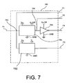
- control circuit 700 for generating control voltages F1-F4 to drive pass-transistors M1-M9 is shown in figure 7 .
- Such control circuit 700 is, particularly, arranged to receive as input the first control voltage F1 and to generate as output the second F2, third F3 and fourth F4 control voltage.
- the control circuit 700 is also arranged to provide the same first control voltage F1 as output.
- the first control voltage F1 is generated by a logic circuitry associated with the analog-to-digital conversion block 101 for controlling such block.
- the low logic level of the first control voltage F1 corresponds to the ground potential GND, the high logic level of the same first control voltage F1 corresponds to the first supply potential VDD.
- the control circuit 700 comprises a first 701 and a second 702 level shifting block, particularly a first 701 and a second 702 dual supply level shifter.
- the first level shifter 701 is connected between the first VDD and the second VDD1V8 supply potential and the ground potential GND.
- the second level shifter 702 is connected between the first VDD supply potential, the battery voltage Vin and the ground potential GND.
- the first level shifter 701 comprises an input 703 for receiving the first control voltage F1 and an output 704 for providing the second control voltage F2 as result of the level shifting operation performed on the first control voltage F1.
- the second control voltage F2 has its low logic level corresponding to the ground potential GND and its high logic level corresponding to the second supply potential VDD1V8.
- the second level shifter 702 has its input connected to the same input 703 of the first level shifter 701 for receiving the first control voltage F1.
- the second level shifter 702 is configured to provide as output the third control voltage F3 resulting from the shifting of such first control voltage F1.
- the third control voltage F3 has its low logic level corresponding to the ground potential GND and its high logic level corresponding to the battery voltage Vin.
- control circuit 700 comprises an inverter 705 connected between the second supply potential VDD1V8 and the ground potential GND.
- Such inverter 705 has its input connected to the output 704 of the first level shifter 701 to receive the second control voltage F2.
- the inverter 705 is arranged to generate as output the fourth control voltage F4 which has its low logic level corresponding to the ground potential GND and its high logic level corresponding to the second supply potential VDD1V8.
- pass-transistors M5-M6 have their bulk nodes connected to the ground potential GND. Even if not explicitly shown in figure 2 , the bulk nodes of pass-transistors M1-M4, M7-M9 and of transistor M p are connected to the higher voltage in the circuit, i.e. the battery voltage Vin.
- the input block 102 of the AD conversion device 100 of the invention comprises the pass-transistors M1-M9 described above to avoid reliability problems that could arise in recent technologies whenever the conversion device 100 itself is put in power-down mode.
- the output node 5 of the first resistive network 103 would reach the input voltage Vin, i.e. the battery voltage, if no current flows through the first resistor R 1 . This would result in an excessive increase of drain-source operating voltage across the PMOS transistor M P .
- the first control voltage F1 assumes its low level (logic 0) when the conversion device 100 is in the active mode to switch-on the first pass-transistor M1 (P-MOS) and to maintain both fifth M5 and sixth M6 pass-transistors (N-MOS) switched-off.
- the first control voltage F1 assumes its high level (logic 1) when the conversion device 100 is in the power-down mode to switch-off the first pass-transistor M1 and to switch-on the fifth M5 and sixth M6 pass-transistors.
- the second F2 and fourth F4 control voltage are complementary logical signal having, for example, their respective high levels shifted to the second supply potential VDD1V8.
- the second control voltage F2 assumes its low level, i.e. GND, to switch-on the second pass-transistor M2
- the fourth control voltage F4 assumes the high level to maintain the seventh M7, the eighth M8 and ninth M9 pass-transistors switched-off.
- the second F2 and fourth F4 control voltage are configured to switch-off the second pass-transistor M2 and to switch-on the seventh M7, the eighth M8 and ninth M9 pass-transistor, respectively.
- the third control voltage F3 is a digital signal having its high level shifted to the battery voltage Vin.
- the third control voltage F3 assumes its low level to switch-on both the third M3 and the fourth M4 pass-transistor.
- the third control voltage F3 is high to switch-off both pass-transistors M3 and M4.
- pass-transistors M3 and M4 allow, advantageously, to disconnect the first resistor R 1 , and therefore also the input voltage Vin, from the input block 102 when the conversion device 100 is in such power-down mode.
- pass-transistors M7 and M8 connect, respectively, the intermediate node 13 and the first current terminal 10 to the second supply potential VDDlV8. Therefore, it is guaranteed that, even in power-down mode, the drain-source voltages of both P-MOS transistor M P and pass-transistors M3, M4 are maintained under their maximum operative voltage.
- pass-transistors M5, M6, M9 reset the operational amplifier 106 by isolating it from the remaining circuitry.
- the second pass-transistor M2 is switched-off in power-down mode to avoid current consumption between the second supply potential VDD1V8 and ground GND through the resistive path defined by the resistor R 4 .
- the smart-phone battery is usually connected to a modem/application processor chip so that a sense resistance is present between the ground potential GND of the chip and the battery cathode. Since this sense resistance is of the order of tens of milliohms, the voltage drop across it has been for long time considered negligible. Since nowadays the current consumption for smart-phones and tablets is rising, the voltage drop across the sense resistance can reach a relevant value of e.g. one hundred millivolts.
- the input block 102 of the conversion device 100 of the invention further comprises an optional third resistive network 107 connected between the output terminal 4 and a first output node 11 of the same input block 102.
- Such first output node 11 is connected to a third input 12 of the analog-to-digital conversion block 101.
- the first output node 11 is configured to be switched, through a switch Sw, to the ground potential GND in a first operative condition of the conversion device 100, i.e. when the battery voltage Vin has to be converted versus the ground potential GND.
- a second operative condition of the conversion device 100 i.e. when the battery voltage Vin has to be converted versus the first reference potential Vbc
- the first output node 11 is connected by the switch Sw to such first reference potential Vbc.
- the third resistive network 107 comprises a third resistor R 2B connected between the output terminal 4 and the first output node 11 of the input block 102.
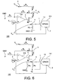
- FIG. 5 A way of operating of the AD conversion device 100 for converting the battery voltage Vin can be described with reference to figures 5 and 6 .
- the AD conversion device 100 in the active mode and in the first operative condition is shown in figure 5 .
- a parallel connection of the second R 2A and third R 2B resistor is represented by a fourth resistor R 2 .
- a voltage V A at the output node 5 is fixed by the negative feedback of a buffer loop comprising the operational amplifier 106, the resistors R3 and R4, and the P-MOS transistor M P .
- V A V REF ⁇ R 3 + R 4 R 3
- R 3 ⁇ R 2 ⁇ V OUT R 2 R 1 ⁇ V in - R 2 R 3 ⁇ R 1 + R 3 + R 4 R 1 ⁇ V REF
- the first term of the expression (5) of the voltage signal Vout depends on the battery voltage Vin.
- the factor of this dependence is the scaling factor (R2/R1).
- the second term of expression (5) depends on the reference voltage V REF , which is the internal reference voltage (Full Scale Range or FSR) of the GPADC conversion block 101. This term is negative, so that, it produces a downward voltage shifting.
- V out V REF R 2 R 1 ⁇ V in - R 2 R 3 ⁇ R 1 + R 3 + R 4 R 1 ⁇ V REF
- V REF R 2 R 1 ⁇ V in V REF - R 2 R 3 ⁇ R 1 + R 3 + R 4 R 1
- a maximum value for the voltage signal Vout i.e. Vout MAX
- Vout MAX should preferably be sufficiently below the value chosen for the voltage V A of the output node 5.
- the P-MOS transistor M P is maintained outside its linear operation region.
- the same maximum value of the voltage signal Vout MAX should be low enough to avoid the introduction of reliability problems into the GPADC conversion block 101.
- Vout MIN a minimum value of the voltage signal Vout, i.e. Vout MIN , should be sufficiently above 0, for example it can assume a value of tens of millivolts. In fact, when Vout tends to 0, the second current I 2 also tends to 0, producing polarization problems for PMOS transistor M P .
- the voltage signal Vout generated at the output terminal 4 as a consequence of scaling and shifting operations performed by the input block 102 on the input voltage signal Vin can assume values in a respective range between the maximum value Vout MAX and the minimum value Vout MIN above mentioned.
- resistors R 1 , R 2 , R 3 and R 4 can be chosen for example as:
- the electronic conversion device 100 of the present invention advantageously, involves additional capacitor C AUX in the conversion block 101 that are about ten times smaller than the corresponding capacitor of a GPADC converter known in the art.
- the conversion device 100 of the invention leads to an area increase which is significantly lower than the increase of the approaches known in the art.
- Figure 6 shows schematically the AD conversion device 100 of the invention in the active mode and in the second operative condition.
- the voltage signal Vout generated by the input block 102 is obtained by the sum of the expression in (5) with another term that takes into account the effect of the first reference potential Vbc through the third resistor R2B.
- the expression (8) represents the scaled/shifted value of the "true battery".
- the input block 102 of AD conversion device 100 of the invention has the advantage of consuming current only during the sampling phase of a battery voltage conversion, otherwise it is powered-down.
- the invention advantageously allows to have a limited attenuation of the signal at the summing nodes of such block 101, so avoiding an unwanted reduction of the signal-to-noise performance.
- the noise added by the input block 102 does not affect of the noise performance.
Abstract
- an analog-to-digital conversion block (101) having a first input (1) for receiving a voltage signal (Vout) to be converted on the basis of a reference voltage signal (VREF) provided to a second input (2) of the same analog-to-digital conversion block (101);
- an input block (102) having an input terminal (3) and an output terminal (4) connected to the first input (1) of the analog-to-digital conversion block (101).
- a first resistive network (103) operatively connected to both the input terminal (3) and the output terminal (4);
- a second resistive network (104) connected between the output terminal (4) and a reference potential (GND).
Description
- The present disclosure relates to the field of Analog-to-Digital Converters (ADCs) and more particularly concerns an electronic analog-to-digital conversion device.
- In many electronic applications, a measure of analog single-ended low frequency signals is often required. Usually, a General-Purpose Analog-to-Digital Converter or GPADC is used to convert such analog signals from the analog domain to the digital domain while measuring them. One of these electronic applications is, for example, mobile phones wherein many analog signals have to be continuously monitored to keep the microprocessor equipping each mobile phone device aware of the state of the device itself.
- According to the analog-to-digital conversion procedure, an analog signal to be converted, for example a voltage signal having a respective range of variation, is compared to a reference range often indicated as Full Scale Range or FSR. Usually, a single FSR is provided whereas different signals to be converted can have each a different range. In view of this, scaling voltage signals before starting the analog-to-digital conversion is a common practice in order to align the ranges of such voltage signals to the reference range. Moreover, most of the voltage signals to be converted are single-ended signals and referred to ground, whereas few voltage signals have their respective ranges shifted with respect to the ground reference. Therefore, for such few voltage signals also a shifting of the voltage signal's range is required.
- An example of a shifted voltage signal is the battery voltage in mobile phones. The analog-to-digital conversion of the battery voltage is always required in such devices. For example, the battery voltage range having a minimum value of 2.3V (battery low) and a maximum value of 4.8V (battery charged) is usually converted using a reference FSR=1.6V. In this case, the battery range is 4.8V-2.3V=2.5V and such range is scaled into 1.6V range by applying 1.6V/2.5V = 0.64 as a scaling factor. After the scaling process, the resulting range is:


- Furthermore, a voltage shifting is required as indicated above. This is obtained by subtracting the minimum scaled voltage Vmin to both voltages resulting from the scaling process, so that:

- It should be observed that whereas a voltage scaling can be implemented with an electronic circuit without efforts, voltage shifting is much more complicated to be circuitally implemented.
- A well-known solution in the art to convert a analog battery voltage into a digital domain is based on charge redistribution provided by a GPADC device operating with a Successive Approximation Register or SAR. A General-Purpose ADC SAR device is disclosed, for example, in document
US 2003/0231130 A1 . -
Figure 3 of the present application shows an exemplary structure of aGPADC SAR device 500 known in the art. - The
GPADC SAR device 500 comprises acomparator 501 having a first input A connected to acapacitive DAC array 502 for providing a voltage representing the difference between a sampled input voltage VM, applied to afirst input terminal 1 of thedevice 500, and a fraction of a reference voltage VREF, applied to asecond input terminal 2 of the same device. Such fraction is obtained by connecting only a portion of the capacitors of thearray 502 to the reference voltage VREF. This operation is managed by a SAR algorithm controller. A second input B of thecomparator 501 and athird input terminal 12 of theGPADC device 500 are both connected to the ground potential GND. The input voltage signal VM of theGPADC SAR device 500 is sampled and stored on the DACcapacitive array 502. This solution is both simple and has the advantage to allow the scaling down of the input voltage VM stored in theDAC 502 to a voltage equal to the reference voltage VREF only by charging a prefixed fraction of capacitors comprised in theDAC array 502. - In the
GPADC SAR device 500, the voltage shifting is achieved by adding a further capacitor, particularly capacitor CAUX infigure 3 , to the summing node of thecapacitive array 502 corresponding to the first input A ofcomparator 501. In the case of a battery voltage shifting, the additional capacitor CAUX is substantially as big as the wholecapacitive array 502. For example, assuming the input voltage signal VM in the range (2.3V - 4.8V), a value for the additional capacitor CAUX is obtained by the equation:
wherein Carray corresponds substantially to the total capacitance of thecapacitive array 502. Therefore, the resulting area occupation ofsuch array 502 is roughly doubled. - Moreover, the total capacitances connected to the first A input of
comparator 501 increases the voltage attenuation of both the input voltage signal VM and the comparison voltage generated by the SAR algorithm. Therefore, the signal to noise ratio S/N at the input of thecomparator 501 is significantly worsened. Such disadvantage of theGPADC SAR device 500 is particularly relevant in new technologies wherein supply voltages are gradually reduced. - The GPADC
SAR device 500 has further disadvantages. In fact, since the input voltage signal VM to be converted can reach a value up to 4.8V (corresponding to the fully charged battery), a voltage of the same value has to be made available inside theGPADC SAR device 500. In recent technologies, for example for a 40 nm manufacturing process or subsequent, reliability issues appear if the voltage inside the circuit overcome very limited values as 3.3V or even 2.5V: so many modifications have to be introduced to manage such a battery voltage value inside thedevice 500 which lead to area and complexity increases as well as growth in power consumption. - In an alternative solution described with reference to
figure 4 , aresistive voltage divider 600 can be provided at the input of theGPADC SAR device 500. Particularly,such voltage divider 600 comprises resistors RA, RB to scale the input voltage VM in order to generate a properly scaled voltage VM' at the input of theGPADC SAR device 500. However, the voltage shifting is still performed inside the GPADCSAR 500 by using the above mentioned additional capacitor CAUX. - Such alternative solution ensures a complexity reduction of the
GPADC SAR device 500 compared with the previous one and, therefore, is more reliable. However, with reference to the chip area occupation involved, even if the additional area occupied by the resistive voltage divider would probably compensate for the area saved inside theGPADC SAR device 500 determined by reliability drawbacks prevention, the area required for voltage shifting, which is influenced by capacitor CAUX, is not reduced at all. Therefore, also such alternative solution suffers of a non negligible increase in area occupation. - It is an object of the present invention to provide an electronic analog-to-digital conversion device for converting a voltage signal into a digital signal which ensures better performances in term of chip area saving if compared to the known solutions.
- Another object of the invention is to provide an electronic analog-to-digital conversion device which ensures better performances in term of noise immunity if compared to the known solutions.
- The above objects are reached by an electronic analog-to-digital conversion device according to
independent claim 1. Such conversion device comprises: - an analog-to-digital conversion block having a first input for receiving a voltage signal to be converted on the basis of a reference voltage signal provided to a second input of the same analog-to-digital conversion block;
- an input block having an input terminal and an output terminal connected to the first input of the analog-to-digital conversion block.
- The input block is arranged for processing an input voltage signal applied to the input terminal to generate the voltage signal at the output terminal. The input block comprises:
- a first resistive network operatively connected to both the input terminal and the output terminal;
- a second resistive network connected between the output terminal and a reference potential.
- The input block is characterized by comprising an active network connected between an output node of the first resistive network and the output terminal. The active network has a first input terminal directly connected to the second input of the analog-to-digital conversion block for receiving the same reference voltage signal provided to the second input so that the input voltage signal is processed by the input block on the basis of such reference voltage signal.
- Further embodiments of the invention are described in the dependent claims 2-18.
- It is an object of the present invention also a portable communication apparatus in accordance with claim 19 and a method for converting a voltage signal in accordance with claim 20.
- Further features and advantages of the present invention will become more apparent from the following detailed description of exemplary but no-limiting embodiments thereof, as illustrated in the attached figures, in which:
-
Fig. 1 shows schematically a block structure of an electronic analog-to-digital conversion device according to the present invention; -
Fig. 2 shows a circuital structure of a preferred embodiment of the electronic analog-to-digital conversion device offigure 1 ; -
Fig. 3 shows a schematic circuital structure of a General Purpose Analog-to-Digital Converter (GPADC) operating with a Successive Approximation Register (SAR) in accordance with a solution known in the art; -
Fig. 4 shows schematically the GPADC device offigure 3 having its input connected to a resistive voltage divider known in the art; -
Fig. 5 shows the electronic analog-to-digital conversion device offigure 2 in active mode and in a first operative condition; -
Fig. 6 shows the electronic analog-to-digital conversion device offigure 2 in active mode and in a second operative condition; -
Fig. 7 shows schematically a control circuit for generating control voltages to drive pass-transistors of the analog-to-digital conversion device offigure 2 . - In the attached figures similar or identical elements are indicated using the same reference numbers.
- With reference to
figure 1 , a block structure of an electronic analog-to-digital conversion device according to the present invention is indicated with thereference number 100. In the following the electronic analog-to-digital conversion device 100 is also indicated AD conversion device or simply conversion device. - Such
AD conversion device 100 can be used in many electronic applications wherein a conversion of analog voltage signals from the analog domain to the digital domain is required. In more detail, the present invention can be advantageously used in portable communication apparatuses, such as for example mobile phones, smart-phones or tablets, wherein many analog voltage signals have to be continuously converted and such signals have each a respective range of variation which is also shifted with respect to a ground reference. Therefore, shifting and scaling operations performed on such voltage signals before starting the analog-to-digital conversion are necessary. - Particularly, the
AD conversion device 100 comprises an analog-to-digital conversion block 101 and aninput block 102. The analog-to-digital conversion block 101 comprises afirst input 1 for receiving a voltage signal Vout to be converted on the basis of a reference voltage signal VRFF provided to asecond input 2 of the same analog-to-digital conversion block 101. Such analog-to-digital conversion block 101 corresponds to a General-Purpose Analog-to-Digital Converter or GPADC known in the art (see for example,figure 3 ) and it will not be described in more detail in the following. - The
input block 102 comprises aninput terminal 3 for receiving an input voltage signal vin and anoutput terminal 4 which is connected to thefirst input 1 of the analog-to-digital conversion block 101. Particularly, theinput block 102 is arranged for processing the input voltage signal Vin applied to theinput terminal 3 to generate such voltage signal Vout at theoutput terminal 4. For example, the input voltage signal Vin is an analog voltage signal representing the battery voltage of a mobile-phone, smart-phone or tablet. - In an embodiment, such input voltage signal Vin can assume values in a range between a maximum value Vinmax and a minimum value Vinmin. In a further embodiment, the minimum value Vinmin of the input voltage signal Vin is greater than 0. With reference to the example above, the maximum value Vinmax is about 4.8V, corresponding to a battery fully charged, and the minimum value Vinmin is about 2.3V, corresponding to a battery low.
- Moreover, in the present disclosure, the term "processing" the input voltage signal Vin generally indicates both shifting and scaling operations performed on the same input voltage signal Vin by the
input block 102 to generate the voltage signal Vout to be provided to the analog-to-digital conversion block 101. - Moreover, the
input block 102 comprises a firstresistive network 103 operatively connected both to theinput terminal 3 and to theoutput terminal 4. In more detail, with reference tofigure 2 , such firstresistive network 103 comprises a first resistor R1 directly connected to theinput terminal 3 and to anoutput node 5 of the firstresistive network 103.Such output node 5 is operatively connected to theoutput terminal 4. - The
input block 102 also comprises a secondresistive network 104 connected between theoutput terminal 4 and a reference potential, such as the ground potential GND. With reference tofigure 2 , such secondresistive network 104 comprises a second resistor R2A. - In addition, the
input block 102 comprises anactive network 105 connected between theoutput node 5 of the firstresistive network 103 and theoutput terminal 4. Suchactive network 105 has, advantageously, afirst input terminal 6 directly connected to thesecond input 2 of the analog-to-digital conversion block 101 for receiving the same reference voltage signal VREF applied to suchsecond input 2 of theconversion block 101. In this way the input voltage signal Vin is processed (e.g., scaled and shifted) by theinput block 102 on the basis of such reference voltage signal VREF. - With reference to
figure 2 , theactive network 105 comprises anoperational amplifier 106 having a first 7 and a second 8 differential input and a single-endedoutput 9. Suchoperational amplifier 106 is connected between a first supply potential VDD corresponding to theconversion device 100 supply potential, and the ground potential GND. Such first supply potential VDD is lower than the battery voltage Vin and is generated starting from such battery voltage. - The first
differential input 7 of theoperational amplifier 106 is connected to thefirst input terminal 6 above mentioned through a first electronic circuit M1. The seconddifferential input 8 is connected to theoutput node 5 of the firstresistive network 103 through a second electronic circuit M2, R4, M3. - In more detail, the first electronic circuit M1 comprises a first pass-transistor M1, for example a P-MOS transistor, connected between the first
differential input 7 of theoperational amplifier 106 and thefirst input terminal 6 of theactive network 105. A command terminal of such first pass-transistor M1 is driven by a first control voltage F1. - The second electronic circuit M2, R4, M3 comprises a second M2 (P-MOS type) and a third M3 (P-MOS type) pass-transistor with a resistor R4 in between so that the second M2 and third M3 pass-transistors and such resistor R4 are connected in series between the second
differential input 8 of theoperational amplifier 106 and theoutput node 5 of the firstresistive network 103. The second M2 and the third M3 pass-transistor have command terminals driven by a second control voltage F2 and by a third control voltage F3, respectively. - Furthermore, the
active network 105 comprises an output stage MP, M4 connected between the above mentionedoutput node 5 of the firstresistive network 103 and theoutput terminal 4. Such output stage comprises a transistor MP, for example a P-MOS transistor, having a firstcurrent terminal 10 connected to theoutput node 5 through a fourth pass-transistor M4, and a second current terminal connected to saidoutput terminal 4. A command terminal G representing the activation terminal for transistor MP is connected to the single-endedoutput 9 of theoperational amplifier 106. - It should be observed that the fourth pass-transistor M4 is a P-MOS having a respective command terminal driven by the third control voltage F3.
- Moreover, the
active network 105 comprises a further resistor R3 connected between the seconddifferential input 8 of theoperational amplifier 106 and the ground potential GND. - The
active network 105 of theconversion device 100 further comprises a fifth M5/a sixth M6 pass-transistor connected between the first 7/the second 8 differential input of theoperational amplifier 106 and the ground potential GND. Both fifth M5 and a sixth M6 pass-transistors are N-MOS having a command terminal driven by the first control voltage F1. - Moreover, the
active network 105 comprises a seventh pass-transistor M7 (P-MOS type) connected between a second supply potential VDD1V8 and anode 13 interposed between the third M3 pass-transistor and the resistor R4. This second supply potential VDD1V8 is a system voltage which is available in the system when the battery voltage Vin is above the minimum voltage value Vinmin. In this condition, such second supply potential VDD1V8 is available in the system even if the first supply potential VDD is off. - A eighth pass-transistor M8 (P-MOS type) is connected between the same second supply potential VDD1V8 and the first
current terminal 10 of PMOS transistor Mp. A ninth pass transistor M9 (P-MOS type) is connected between the second supply potential VDD1V8 and the single-endedoutput 9 of theoperational amplifier 106. All pass-transistors M7, M8 and M9 have their command terminals driven by a fourth control voltage F4. - It should be observed that the above mentioned control voltages-F1-F4 are digital signals that can assume either a low level (logic 0) or a high level (logic 1). Therefore, all the above mentioned pass-transistors M1-M9 can assume ON/OFF state on the basis of such digital signals F1-F4 applied to their command terminals.
- An example of a
control circuit 700 for generating control voltages F1-F4 to drive pass-transistors M1-M9 is shown infigure 7 .Such control circuit 700 is, particularly, arranged to receive as input the first control voltage F1 and to generate as output the second F2, third F3 and fourth F4 control voltage. Thecontrol circuit 700 is also arranged to provide the same first control voltage F1 as output. - It should be observed that the first control voltage F1 is generated by a logic circuitry associated with the analog-to-
digital conversion block 101 for controlling such block. The low logic level of the first control voltage F1 corresponds to the ground potential GND, the high logic level of the same first control voltage F1 corresponds to the first supply potential VDD. - In a preferred embodiment, the
control circuit 700 comprises a first 701 and a second 702 level shifting block, particularly a first 701 and a second 702 dual supply level shifter. In more detail, thefirst level shifter 701 is connected between the first VDD and the second VDD1V8 supply potential and the ground potential GND. Thesecond level shifter 702 is connected between the first VDD supply potential, the battery voltage Vin and the ground potential GND. - The
first level shifter 701 comprises aninput 703 for receiving the first control voltage F1 and anoutput 704 for providing the second control voltage F2 as result of the level shifting operation performed on the first control voltage F1. The second control voltage F2 has its low logic level corresponding to the ground potential GND and its high logic level corresponding to the second supply potential VDD1V8. - The
second level shifter 702 has its input connected to thesame input 703 of thefirst level shifter 701 for receiving the first control voltage F1. Thesecond level shifter 702 is configured to provide as output the third control voltage F3 resulting from the shifting of such first control voltage F1. The third control voltage F3 has its low logic level corresponding to the ground potential GND and its high logic level corresponding to the battery voltage Vin. - In addition, the
control circuit 700 comprises aninverter 705 connected between the second supply potential VDD1V8 and the ground potential GND.Such inverter 705 has its input connected to theoutput 704 of thefirst level shifter 701 to receive the second control voltage F2. Theinverter 705 is arranged to generate as output the fourth control voltage F4 which has its low logic level corresponding to the ground potential GND and its high logic level corresponding to the second supply potential VDD1V8. - With reference to
figure 2 , pass-transistors M5-M6 have their bulk nodes connected to the ground potential GND. Even if not explicitly shown infigure 2 , the bulk nodes of pass-transistors M1-M4, M7-M9 and of transistor Mp are connected to the higher voltage in the circuit, i.e. the battery voltage Vin. - The
input block 102 of theAD conversion device 100 of the invention comprises the pass-transistors M1-M9 described above to avoid reliability problems that could arise in recent technologies whenever theconversion device 100 itself is put in power-down mode. In fact, for example, in such power-down mode, theoutput node 5 of the firstresistive network 103 would reach the input voltage Vin, i.e. the battery voltage, if no current flows through the first resistor R1. This would result in an excessive increase of drain-source operating voltage across the PMOS transistor MP. - Particularly, the first control voltage F1 assumes its low level (logic 0) when the
conversion device 100 is in the active mode to switch-on the first pass-transistor M1 (P-MOS) and to maintain both fifth M5 and sixth M6 pass-transistors (N-MOS) switched-off. To avoid reliability problems, the first control voltage F1 assumes its high level (logic 1) when theconversion device 100 is in the power-down mode to switch-off the first pass-transistor M1 and to switch-on the fifth M5 and sixth M6 pass-transistors. - As described with reference to
figure 7 , the second F2 and fourth F4 control voltage are complementary logical signal having, for example, their respective high levels shifted to the second supply potential VDD1V8. In more detail, when theconversion device 100 is in the active mode, the second control voltage F2 assumes its low level, i.e. GND, to switch-on the second pass-transistor M2, and the fourth control voltage F4 assumes the high level to maintain the seventh M7, the eighth M8 and ninth M9 pass-transistors switched-off. To avoid reliability problems, when theconversion device 100 is in the power-down mode, the second F2 and fourth F4 control voltage are configured to switch-off the second pass-transistor M2 and to switch-on the seventh M7, the eighth M8 and ninth M9 pass-transistor, respectively. - The third control voltage F3 is a digital signal having its high level shifted to the battery voltage Vin. In more detail, when the
conversion device 100 is in the active mode, the third control voltage F3 assumes its low level to switch-on both the third M3 and the fourth M4 pass-transistor. When theconversion device 100 is in the power-down mode, the third control voltage F3 is high to switch-off both pass-transistors M3 and M4. - It should be observed that pass-transistors M3 and M4 allow, advantageously, to disconnect the first resistor R1, and therefore also the input voltage Vin, from the
input block 102 when theconversion device 100 is in such power-down mode. In addition, in the power-down mode, pass-transistors M7 and M8 connect, respectively, theintermediate node 13 and the firstcurrent terminal 10 to the second supply potential VDDlV8. Therefore, it is guaranteed that, even in power-down mode, the drain-source voltages of both P-MOS transistor MP and pass-transistors M3, M4 are maintained under their maximum operative voltage. - During the power-down mode of
conversion device 100, pass-transistors M5, M6, M9 reset theoperational amplifier 106 by isolating it from the remaining circuitry. In addition, the second pass-transistor M2 is switched-off in power-down mode to avoid current consumption between the second supply potential VDD1V8 and ground GND through the resistive path defined by the resistor R4. - Furthermore, for the analog-to-digital conversion of a battery voltage in the most recent mobile-phones and smart-phones, the following situation can arise. The smart-phone battery is usually connected to a modem/application processor chip so that a sense resistance is present between the ground potential GND of the chip and the battery cathode. Since this sense resistance is of the order of tens of milliohms, the voltage drop across it has been for long time considered negligible. Since nowadays the current consumption for smart-phones and tablets is rising, the voltage drop across the sense resistance can reach a relevant value of e.g. one hundred millivolts.
- For these reasons, in smart-phones and tablets is now of interest to convert the battery voltage Vin both versus the ground potential GND, which can be considered the effective voltage available for the system, and also versus the battery cathode, i.e. a first reference potential Vbc, in order to have an accurate measurement of the battery voltage itself or "true" battery voltage.
- In view of this, with reference to
figures 1 and2 , the input block 102 of theconversion device 100 of the invention further comprises an optional thirdresistive network 107 connected between theoutput terminal 4 and afirst output node 11 of thesame input block 102. Suchfirst output node 11 is connected to athird input 12 of the analog-to-digital conversion block 101. - In more detail, the
first output node 11 is configured to be switched, through a switch Sw, to the ground potential GND in a first operative condition of theconversion device 100, i.e. when the battery voltage Vin has to be converted versus the ground potential GND. In a second operative condition of theconversion device 100, i.e. when the battery voltage Vin has to be converted versus the first reference potential Vbc, thefirst output node 11 is connected by the switch Sw to such first reference potential Vbc. - With reference to
figure 2 , the thirdresistive network 107 comprises a third resistor R2B connected between theoutput terminal 4 and thefirst output node 11 of theinput block 102. - A way of operating of the
AD conversion device 100 for converting the battery voltage Vin can be described with reference tofigures 5 and 6 . Particularly, theAD conversion device 100 in the active mode and in the first operative condition is shown infigure 5 . In suchfigure 5 , a parallel connection of the second R2A and third R2B resistor is represented by a fourth resistor R2. - With reference to
figure 5 , a voltage VA at theoutput node 5 is fixed by the negative feedback of a buffer loop comprising theoperational amplifier 106, the resistors R3 and R4, and the P-MOS transistor MP. - More in detail, a current I3 flowing in the feedback branch of the buffer comprising resistors R3 and R4 can be expressed by:

- Thus, the voltage VA at the
output node 5 is:
- A first current I1 flowing in the first resistor R1 is:

- Since the P-MOS transistor MP acts as a current follower, the current flowing through it, i.e. a second current I2, is:

- The resulting voltage signal Vout generated by the
input block 102 is, therefore:
- The first term of the expression (5) of the voltage signal Vout depends on the battery voltage Vin. The factor of this dependence is the scaling factor (R2/R1).
- The second term of expression (5) depends on the reference voltage VREF, which is the internal reference voltage (Full Scale Range or FSR) of the
GPADC conversion block 101. This term is negative, so that, it produces a downward voltage shifting. - It is relevant to notice that the shifting is proportional to the reference voltage VREF. By comparing the output voltage Vout of (5) with the reference voltage VREF, from a mathematical point of view, the
GPADC conversion block 101 has to manage the ratio:
- So an accurate shifting and scaling can be performed in the limit of the reference voltage VREF precision which is generally well guaranteed in recent design.
- In order to ensure a suitable polarization for the input block 102 of the
conversion device 100, a maximum value for the voltage signal Vout, i.e. VoutMAX, should preferably be sufficiently below the value chosen for the voltage VA of theoutput node 5. In this way, the P-MOS transistor MP is maintained outside its linear operation region. Moreover, the same maximum value of the voltage signal VoutMAX should be low enough to avoid the introduction of reliability problems into theGPADC conversion block 101. - In addition, a minimum value of the voltage signal Vout, i.e. VoutMIN, should be sufficiently above 0, for example it can assume a value of tens of millivolts. In fact, when Vout tends to 0, the second current I2 also tends to 0, producing polarization problems for PMOS transistor MP.
- In other words, the voltage signal Vout generated at the
output terminal 4 as a consequence of scaling and shifting operations performed by theinput block 102 on the input voltage signal Vin, can assume values in a respective range between the maximum value VoutMAX and the minimum value VoutMIN above mentioned. Such respective range of values (VoutMAX - VoutMIN) can be further scaled and shifted by theGPADC conversion block 101. These further scaling and shifting operations can be performed to reach a desired scaled value if the scaling performed by theinput block 102 was not enough and to further down-shift the range itself to remove the effect of a non-zero value for VoutMIN, i.e. to obtain VoutMIN=0 as low value. - For example, assuming that values of the battery voltage Vin are in the range (2.3V - 4.8V) and the reference voltage VRFF=1.6V, the values for resistors R1, R2, R3 and R4 can be chosen for example as:
- R1=10kΩ, R2=6.4kΩ, R3=216kΩ, R4=53kΩ.
- These values lead to a range for the voltage signal Vout that is (0.149V - 1.749V), allowing a correct polarization for the
input block 102 wherein the first supply voltage VDD=2.2V and the voltage of theoutput node 5 is VA=1.99V. - Since this range is already scaled to the internal FSR, in fact 1.749-0.149=1.6V, no further scaling operation will be requested in the
GPADC conversion block 101 for converting the voltage signal Vout into the digital domain. On the other hand a down-shift of 0.149V is needed. This down-shift is performed by theconversion block 101, for example the conversion block offigure 3 . In more detail, the requested down-shift is obtained by using an additional capacitor CAUX having a value in accordance with the following equation:
- By comparing equation (6) with the result of equation (1') above, contrary to the solution in accordance with the known art wherein CAUX was 0.92*Carray, the
electronic conversion device 100 of the present invention, advantageously, involves additional capacitor CAUX in theconversion block 101 that are about ten times smaller than the corresponding capacitor of a GPADC converter known in the art. - Particularly, thanks to the area saving resulting from such drastic reduction of additional capacitor CAUX size in the capacitive arrays of
GPADC conversion block 101, theconversion device 100 of the invention leads to an area increase which is significantly lower than the increase of the approaches known in the art. -
Figure 6 shows schematically theAD conversion device 100 of the invention in the active mode and in the second operative condition. - In this case, for a superposition principle, the voltage signal Vout generated by the
input block 102 is obtained by the sum of the expression in (5) with another term that takes into account the effect of the first reference potential Vbc through the third resistor R2B. In addition, the input voltage signal Vin in (5) has to be replaced by Vin-Vint+Vbc wherein Vint represents a value of a "true battery", i.e, the battery voltage without the effect of the sense resistance above mentioned. Therefore, the resulting expression is:
- Since the voltage signal Vout to be converted is now referred to the first reference potential Vbc itself, the contribution in expression (7) relating to such first reference potential Vbc can be cancelled with an opportune choice of resistors values. In particular:

with
- Therefore, if the third resistor R2B assumes the value indicated in expression (9), the expression (8) represents the scaled/shifted value of the "true battery".
- It should be noted that in the
conversion device 100 of the invention, the modifications introduced to make "true battery" conversion possible are, advantageously, almost negligible from an area and complexity point of view. - In addition, the input block 102 of
AD conversion device 100 of the invention has the advantage of consuming current only during the sampling phase of a battery voltage conversion, otherwise it is powered-down. - Moreover, by requiring to introduce a very limited additional capacitance CAUX into the conversion block 101 (as shown in equation (6)), the invention advantageously allows to have a limited attenuation of the signal at the summing nodes of
such block 101, so avoiding an unwanted reduction of the signal-to-noise performance. Referred to this benefit, the noise added by theinput block 102 does not affect of the noise performance. - Regarding the embodiments of the electronic conversion device described above, a person skilled in the art, in order to satisfy contingent needs, can make modifications, adaptations and substitutions of elements with other functional equivalent elements, without departing from the scope of the following claims. Each of the features described as belonging to a possible embodiment can be made independent of the other described embodiments.
Claims (20)
- An electronic analog-to-digital conversion device (100) comprising:- an analog-to-digital conversion block (101) having a first input (1) for receiving a voltage signal (Vout) to be converted on the basis of a reference voltage signal (VREF) provided to a second input (2) of said analog-to-digital conversion block (101);- an input block (102) having an input terminal (3) and an output terminal (4) connected to the first input (1) of the analog-to-digital conversion block (101), said input block (102) being arranged for processing an input voltage signal (Vin) applied to the input terminal (3) to generate said voltage signal (Vout) at the output terminal (4), said input block (102) comprising:- a first resistive network (103) operatively connected to both the input terminal (3) and the output terminal (4);- a second resistive network (104) connected between said output terminal (4) and a reference potential (GND);
said input block (102) being characterized by further comprising:an active network (105) connected between an output node (5) of the first resistive network (103) and said output terminal (4), said active network (105) having a first input terminal (6) directly connected to the second input (2) of the analog-to-digital conversion block (101) for receiving the same reference voltage signal (VREF) provided to said second input (2) so that the input voltage signal (Vin) is processed by the input block (102) on the basis of said reference voltage signal (VREF). - The analog-to-digital conversion device (100) of claim 1, wherein said input voltage signal (Vin) assumes values in a range between a maximum value (Vinmax) and a minimum value (Vinmin).
- The analog-to-digital conversion device (100) of claim 2, wherein the minimum value (Vinmin) of the input voltages signal is greater than 0.
- The analog-to-digital conversion device (100) of claim 1, wherein said active network (105) comprises:• an operational amplifier (106) having:- a first differential input (7) connected to staid first input terminal (6) through a first electronic circuit (M1);- a second differential input (8) connected to the output node (5) of the first resistive network (103) through second electronic circuit (M2, R4, M3);• an output stage (MP, M4) connected between said output node (5) and said output terminal (4), said output stage comprising an activation terminal (G) connected to a single-ended output (9) of the operational amplifier (106).
- The analog-to-digital conversion device (100) of claim 4, wherein said first electronic circuit comprises a first pass-transistor (M1) connected between the first differential input (7) of the operational amplifier (106) and said first input terminal (6) and having a command terminal driven by a first control voltage (F1).
- The analog-to-digital conversion device (100) of claim 4, wherein said second electronic circuit comprises a second (M2) and a third (M3) pass-transistors and a first resistor (R4) connected in series among them between the second differential input (8) of the operational amplifier (106) and the output node (5), said second pass-transistor (M2) having a command terminal driven by a second control voltage (F2) and said third pass-transistor (M3) having a command terminal driven by a third control voltage (F3).
- The analog-to-digital conversion device (100) of claim 4, wherein said output stage comprises a transistor (MP) having a first current terminal (10) connected to the output node (5) through a fourth pass-transistor (M4), a second current terminal connected to said output terminal (4) and a command terminal corresponding to said activation terminal (G).
- The analog-to-digital conversion device (100) of claims 6 and 7, wherein said fourth pass-transistor (M4) has a respective command terminal driven by the third control voltage (F3).
- The analog-to-digital conversion device (100) of claim 4, wherein said active network (105) further comprises a second resistor (R3) connected between the second differential input (8) of the operational amplifier (106) and the reference potential (GND).
- The analog-to-digital conversion device (100) of claim 5, wherein said active network (105) further comprises:- a fifth pass-transistor (M5) connected between the first differential input (7) of the operational amplifier (106) and the reference potential (GND), having a command terminal driven by the first control voltage (F1);- a sixth pass transistor (M6) connected between the second differential input (8) of the operational amplifier (106) and the reference potential (GND), having a command terminal driven by the first control voltage (F1).
- The analog-to-digital conversion device (100) of claim 5-7, wherein the active network (105) further comprises:- a seventh pass-transistor (M7) connected between a supply potential (VDD1V8) and a node (13) interposed between the third pass-transistor (M3) and the first resistor (R4),- a eighth pass-transistor (M8) connected between the supply potential (VDD1V8) and the first current terminal (10) of said transistor (Mp),- a ninth pass transistor (M9) connected between the supply potential (VDD1V8) and the single-ended output (9) of the operational amplifier (106),
said seventh, eighth and ninth pass-transistors having their command terminal driven by a fourth control voltage (F4). - The analog-to-digital conversion device (100) of claim 1, wherein said input block (102) further comprises a third resistive network (107) connected between said output terminal (4) and a first output node (11) of the input block (102).
- The analog-to-digital conversion device (100) of claim 12, wherein said first output node (11) is connected to said reference potential (GND) in a first operative condition of the conversion device (100).
- The analog-to-digital conversion device (100) of claim 12, wherein said first output node (11) is connected to a first reference potential (Vbc) in a second operative condition of the conversion device (100).
- The analog-to-digital conversion device (100) of claim 12, wherein said first output node (11) is connected to a third input (12) of the analog-to-digital conversion block (101).
- The analog-to-digital conversion device (100) of claim 1, wherein said first resistive network (103) comprises a third resistor (R1) connected between the input terminal (3) of the input block (102) and the output node (5).
- The analog-to-digital conversion device (100) of claim 1, wherein said second resistive network (104) comprises a fourth resistor (R2A) connected between the output terminal (4) and the reference potential (GND).
- The analog-to-digital conversion device (100) of claim 12, wherein said third resistive network (107) comprises a fifth resistor (R2B) connected between the output terminal (4) and the first output node (11) of the input block (102).
- A portable communication apparatus comprising the analog-to-digital conversion device (100) according to claim 1.
- Method for converting a voltage signal (Vout) on the basis of a reference voltage signal (VREF) with an electronic analog-to-digital conversion device (100), said device (100) comprising:- an analog-to-digital conversion block (101) having a first input (1) and a second input (2);- an input block (102) having an input terminal (3) and an output terminal (4) connected to the first input (1) of the analog-to-digital conversion block (101), said input block (102) further comprising:the method comprising the steps of:- a first resistive network (103) operatively connected to both the input terminal (3) and the output terminal (4);- a second resistive network (104) connected between said output terminal (4) and a reference potential (GND);- an active network (105) connected between an output node (5) of the first resistive network (103) and said output terminal (4), said active network (105) having a first input terminal (6) directly connected to the second input (2) of the analog-to-digital conversion block (101);- providing an input voltage signal (Vin) to the input terminal (3) of the input block (102),- providing the reference voltage signal (VREF) both to the first input terminal (6) of the active network (105) and to the second input (2) of the analog-to-digital conversion block (101);- performing, by the input block (102), a first scaling and shifting operation on said input voltage signal (Vin) on the basis of the reference voltage signal (VREF) to generate said voltage signal (Vout) applied to said first input (1);- performing, by the analog-to-digital conversion block (101), at least a second shifting operation on said voltage signal (Vout).
Priority Applications (4)
| Application Number | Priority Date | Filing Date | Title |
|---|---|---|---|
| EP12178324.5A EP2690788A1 (en) | 2012-07-27 | 2012-07-27 | Analog-to-digital conversion device |
| IN168DEN2015 IN2015DN00168A (en) | 2012-07-27 | 2013-07-17 | |
| PCT/EP2013/065111 WO2014016185A1 (en) | 2012-07-27 | 2013-07-17 | Analog-to-digital conversion device |
| US14/412,747 US9219491B2 (en) | 2012-07-27 | 2013-07-17 | Analog-to-digital conversion device |
Applications Claiming Priority (1)
| Application Number | Priority Date | Filing Date | Title |
|---|---|---|---|
| EP12178324.5A EP2690788A1 (en) | 2012-07-27 | 2012-07-27 | Analog-to-digital conversion device |
Publications (1)
| Publication Number | Publication Date |
|---|---|
| EP2690788A1 true EP2690788A1 (en) | 2014-01-29 |
Family
ID=46581840
Family Applications (1)
| Application Number | Title | Priority Date | Filing Date |
|---|---|---|---|
| EP12178324.5A Withdrawn EP2690788A1 (en) | 2012-07-27 | 2012-07-27 | Analog-to-digital conversion device |
Country Status (4)
| Country | Link |
|---|---|
| US (1) | US9219491B2 (en) |
| EP (1) | EP2690788A1 (en) |
| IN (1) | IN2015DN00168A (en) |
| WO (1) | WO2014016185A1 (en) |
Families Citing this family (1)
| Publication number | Priority date | Publication date | Assignee | Title |
|---|---|---|---|---|
| WO2013189925A2 (en) | 2012-06-18 | 2013-12-27 | St-Ericsson Sa | Digital image analysis |
Citations (4)
| Publication number | Priority date | Publication date | Assignee | Title |
|---|---|---|---|---|
| US20030231130A1 (en) | 2002-06-14 | 2003-12-18 | Stmicroelectronics S.R.I. | Method of operating SAR-type ADC and an ADC using the method |
| JP2006153740A (en) * | 2004-11-30 | 2006-06-15 | Fuji Photo Film Co Ltd | Apparatus for detecting residual amount of battery |
| US20090172614A1 (en) * | 2007-12-27 | 2009-07-02 | International Business Machines Corporation | Avoiding device stressing |
| US20100308921A1 (en) * | 2009-06-03 | 2010-12-09 | Jaroslaw Adamski | Leakage current reduction in a power regulator |
Family Cites Families (4)
| Publication number | Priority date | Publication date | Assignee | Title |
|---|---|---|---|---|
| US4942399A (en) * | 1989-03-15 | 1990-07-17 | International Business Machines Corporation | Adaptive flash analog/digital converter for differential input signal |
| US5874909A (en) * | 1996-02-13 | 1999-02-23 | Texas Instruments Incorporated | Analog to digital video converter |
| US5796361A (en) * | 1996-09-25 | 1998-08-18 | Exar Corporation | CCD signal digitizing integrated circuit |
| US7049989B2 (en) * | 2004-10-01 | 2006-05-23 | Smiths Aerospace Llc | Unified analog input front end apparatus and method |
-
2012
- 2012-07-27 EP EP12178324.5A patent/EP2690788A1/en not_active Withdrawn
-
2013
- 2013-07-17 US US14/412,747 patent/US9219491B2/en not_active Expired - Fee Related
- 2013-07-17 IN IN168DEN2015 patent/IN2015DN00168A/en unknown
- 2013-07-17 WO PCT/EP2013/065111 patent/WO2014016185A1/en active Application Filing
Patent Citations (4)
| Publication number | Priority date | Publication date | Assignee | Title |
|---|---|---|---|---|
| US20030231130A1 (en) | 2002-06-14 | 2003-12-18 | Stmicroelectronics S.R.I. | Method of operating SAR-type ADC and an ADC using the method |
| JP2006153740A (en) * | 2004-11-30 | 2006-06-15 | Fuji Photo Film Co Ltd | Apparatus for detecting residual amount of battery |
| US20090172614A1 (en) * | 2007-12-27 | 2009-07-02 | International Business Machines Corporation | Avoiding device stressing |
| US20100308921A1 (en) * | 2009-06-03 | 2010-12-09 | Jaroslaw Adamski | Leakage current reduction in a power regulator |
Non-Patent Citations (2)
| Title |
|---|
| GERSTENHABER M ET AL: "ADC INTERFACE CONDITIONS HIGH-LEVEL SIGNALS", EDN ELECTRICAL DESIGN NEWS, REED BUSINESS INFORMATION, HIGHLANDS RANCH, CO, US, vol. 48, no. 24, 30 October 2003 (2003-10-30), pages 96,98, XP001177623, ISSN: 0012-7515 * |
| VOLPI E ET AL: "Design of a high voltage fully differential driver for a double axis scanning micromirror", RESEARCH IN MICROELECTRONICS AND ELECTRONICS, 2009. PRIME 2009. PH.D, IEEE, PISCATAWAY, NJ, USA, 12 July 2009 (2009-07-12), pages 112 - 115, XP031510377, ISBN: 978-1-4244-3733-7 * |
Also Published As
| Publication number | Publication date |
|---|---|
| WO2014016185A1 (en) | 2014-01-30 |
| US9219491B2 (en) | 2015-12-22 |
| IN2015DN00168A (en) | 2015-06-12 |
| US20150171881A1 (en) | 2015-06-18 |
Similar Documents
| Publication | Publication Date | Title |
|---|---|---|
| US7652604B2 (en) | Programmable analog-to-digital converter for low-power DC-DC SMPS | |
| US8536844B1 (en) | Self-calibrating, stable LDO regulator | |
| CN110663187B (en) | Analog-to-digital converter, measuring device and analog-to-digital conversion method | |
| EP1938455B1 (en) | Providing reference voltage with desired accuracy in short duration to dynamically varying load | |
| US9651962B2 (en) | System and method for a linear voltage regulator | |
| US8284093B2 (en) | Successive approximation A/D converter | |
| US10594303B2 (en) | Temperature sensor circuit and semiconductor device including the same | |
| US9634627B2 (en) | Amplification circuit and analog/digital conversion circuit | |
| US20100259285A1 (en) | Providing feedback in an electronic circuit | |
| US10181857B1 (en) | Analog-to-digital converter error correction | |
| US10090851B2 (en) | Successive approximation type analog-to-digital (A/D) converter | |
| JP2019194855A (en) | Power-cycling of voltage reference | |
| US10224884B2 (en) | Circuit for and method of implementing a multifunction output generator | |
| Zhou et al. | A 245-mA digitally assisted dual-loop low-dropout regulator | |
| JP2002343442A (en) | Method and device for measuring charging current and discharging current of storage battery using direct analog-to-digital conversion of charging replica current /discharging replica current | |
| EP2690788A1 (en) | Analog-to-digital conversion device | |
| JP6527106B2 (en) | Power supply circuit | |
| US20100289683A1 (en) | Reference voltage generation circuit, a/d converter and d/a converter | |
| Wang et al. | A multi-cell battery pack monitoring chip based on 0.35-µm BCD technology for electric vehicles | |
| CN111245383A (en) | Circuit and method for error signal amplification and processing | |
| US20200328759A1 (en) | Da conversion device | |
| US8988113B2 (en) | Comparator circuit having a calibration circuit | |
| Chaubey et al. | Design techniques for zero steady-state output ripple in digital low dropout regulators | |
| EP2403146A1 (en) | Low power analog to digital converter | |
| US20150160667A1 (en) | Power converter and method of use |
Legal Events
| Date | Code | Title | Description |
|---|---|---|---|
| PUAI | Public reference made under article 153(3) epc to a published international application that has entered the european phase |
Free format text: ORIGINAL CODE: 0009012 |
|
| AK | Designated contracting states |
Kind code of ref document: A1 Designated state(s): AL AT BE BG CH CY CZ DE DK EE ES FI FR GB GR HR HU IE IS IT LI LT LU LV MC MK MT NL NO PL PT RO RS SE SI SK SM TR |
|
| AX | Request for extension of the european patent |
Extension state: BA ME |
|
| 17P | Request for examination filed |
Effective date: 20140728 |
|
| RBV | Designated contracting states (corrected) |
Designated state(s): AL AT BE BG CH CY CZ DE DK EE ES FI FR GB GR HR HU IE IS IT LI LT LU LV MC MK MT NL NO PL PT RO RS SE SI SK SM TR |
|
| RAP1 | Party data changed (applicant data changed or rights of an application transferred) |
Owner name: OCT CIRCUIT TECHNOLOGIES INTERNATIONAL LIMITED |
|
| STAA | Information on the status of an ep patent application or granted ep patent |
Free format text: STATUS: THE APPLICATION HAS BEEN WITHDRAWN |
|
| 18W | Application withdrawn |
Effective date: 20180307 |