EP1798768A2 - Halbleiterbauelement und sein Herstellungsverfahren - Google Patents
Halbleiterbauelement und sein Herstellungsverfahren Download PDFInfo
- Publication number
- EP1798768A2 EP1798768A2 EP06026027A EP06026027A EP1798768A2 EP 1798768 A2 EP1798768 A2 EP 1798768A2 EP 06026027 A EP06026027 A EP 06026027A EP 06026027 A EP06026027 A EP 06026027A EP 1798768 A2 EP1798768 A2 EP 1798768A2
- Authority
- EP
- European Patent Office
- Prior art keywords
- semiconductor substrate
- back surface
- receiving element
- light receiving
- semiconductor device
- Prior art date
- Legal status (The legal status is an assumption and is not a legal conclusion. Google has not performed a legal analysis and makes no representation as to the accuracy of the status listed.)
- Withdrawn
Links
- 239000004065 semiconductor Substances 0.000 title claims abstract description 127
- 238000004519 manufacturing process Methods 0.000 title claims description 17
- 239000000758 substrate Substances 0.000 claims abstract description 86
- 238000000034 method Methods 0.000 claims description 18
- 239000000463 material Substances 0.000 claims description 13
- 229910052751 metal Inorganic materials 0.000 claims description 12
- 239000002184 metal Substances 0.000 claims description 12
- 230000000149 penetrating effect Effects 0.000 claims description 11
- 230000002745 absorbent Effects 0.000 claims description 9
- 239000002250 absorbent Substances 0.000 claims description 9
- 238000005286 illumination Methods 0.000 abstract description 2
- 238000009413 insulation Methods 0.000 description 18
- 239000010949 copper Substances 0.000 description 7
- 229910052782 aluminium Inorganic materials 0.000 description 6
- XAGFODPZIPBFFR-UHFFFAOYSA-N aluminium Chemical compound [Al] XAGFODPZIPBFFR-UHFFFAOYSA-N 0.000 description 6
- 229910000679 solder Inorganic materials 0.000 description 6
- RYGMFSIKBFXOCR-UHFFFAOYSA-N Copper Chemical compound [Cu] RYGMFSIKBFXOCR-UHFFFAOYSA-N 0.000 description 5
- 229910052802 copper Inorganic materials 0.000 description 5
- VYPSYNLAJGMNEJ-UHFFFAOYSA-N silicon dioxide Inorganic materials O=[Si]=O VYPSYNLAJGMNEJ-UHFFFAOYSA-N 0.000 description 5
- PXHVJJICTQNCMI-UHFFFAOYSA-N Nickel Chemical compound [Ni] PXHVJJICTQNCMI-UHFFFAOYSA-N 0.000 description 4
- PCHJSUWPFVWCPO-UHFFFAOYSA-N gold Chemical compound [Au] PCHJSUWPFVWCPO-UHFFFAOYSA-N 0.000 description 4
- 239000010931 gold Substances 0.000 description 4
- 229910052737 gold Inorganic materials 0.000 description 4
- 229920002120 photoresistant polymer Polymers 0.000 description 4
- 229910052581 Si3N4 Inorganic materials 0.000 description 3
- 238000000151 deposition Methods 0.000 description 3
- 238000000059 patterning Methods 0.000 description 3
- 238000007747 plating Methods 0.000 description 3
- HQVNEWCFYHHQES-UHFFFAOYSA-N silicon nitride Chemical compound N12[Si]34N5[Si]62N3[Si]51N64 HQVNEWCFYHHQES-UHFFFAOYSA-N 0.000 description 3
- 229910052814 silicon oxide Inorganic materials 0.000 description 3
- 238000004544 sputter deposition Methods 0.000 description 3
- XUIMIQQOPSSXEZ-UHFFFAOYSA-N Silicon Chemical compound [Si] XUIMIQQOPSSXEZ-UHFFFAOYSA-N 0.000 description 2
- 238000010521 absorption reaction Methods 0.000 description 2
- 230000004888 barrier function Effects 0.000 description 2
- 238000005229 chemical vapour deposition Methods 0.000 description 2
- 230000000694 effects Effects 0.000 description 2
- 239000003822 epoxy resin Substances 0.000 description 2
- 238000005530 etching Methods 0.000 description 2
- 239000011521 glass Substances 0.000 description 2
- 238000000227 grinding Methods 0.000 description 2
- 229910052759 nickel Inorganic materials 0.000 description 2
- 238000004806 packaging method and process Methods 0.000 description 2
- 229920000647 polyepoxide Polymers 0.000 description 2
- 230000002265 prevention Effects 0.000 description 2
- 239000010453 quartz Substances 0.000 description 2
- 229920005989 resin Polymers 0.000 description 2
- 239000011347 resin Substances 0.000 description 2
- 229910052710 silicon Inorganic materials 0.000 description 2
- 239000010703 silicon Substances 0.000 description 2
- 239000010936 titanium Substances 0.000 description 2
- BQCADISMDOOEFD-UHFFFAOYSA-N Silver Chemical compound [Ag] BQCADISMDOOEFD-UHFFFAOYSA-N 0.000 description 1
- GWEVSGVZZGPLCZ-UHFFFAOYSA-N Titan oxide Chemical compound O=[Ti]=O GWEVSGVZZGPLCZ-UHFFFAOYSA-N 0.000 description 1
- RTAQQCXQSZGOHL-UHFFFAOYSA-N Titanium Chemical compound [Ti] RTAQQCXQSZGOHL-UHFFFAOYSA-N 0.000 description 1
- NRTOMJZYCJJWKI-UHFFFAOYSA-N Titanium nitride Chemical compound [Ti]#N NRTOMJZYCJJWKI-UHFFFAOYSA-N 0.000 description 1
- 230000005540 biological transmission Effects 0.000 description 1
- 239000007795 chemical reaction product Substances 0.000 description 1
- 230000001419 dependent effect Effects 0.000 description 1
- 238000009713 electroplating Methods 0.000 description 1
- 238000005516 engineering process Methods 0.000 description 1
- 230000002708 enhancing effect Effects 0.000 description 1
- 239000007769 metal material Substances 0.000 description 1
- 238000002156 mixing Methods 0.000 description 1
- 230000003647 oxidation Effects 0.000 description 1
- 238000007254 oxidation reaction Methods 0.000 description 1
- 238000012536 packaging technology Methods 0.000 description 1
- 238000002161 passivation Methods 0.000 description 1
- 239000000049 pigment Substances 0.000 description 1
- 238000005268 plasma chemical vapour deposition Methods 0.000 description 1
- 229910052709 silver Inorganic materials 0.000 description 1
- 239000004332 silver Substances 0.000 description 1
- MZLGASXMSKOWSE-UHFFFAOYSA-N tantalum nitride Chemical compound [Ta]#N MZLGASXMSKOWSE-UHFFFAOYSA-N 0.000 description 1
- 229910052719 titanium Inorganic materials 0.000 description 1
Images


Classifications
-
- H—ELECTRICITY
- H01—ELECTRIC ELEMENTS
- H01L—SEMICONDUCTOR DEVICES NOT COVERED BY CLASS H10
- H01L27/00—Devices consisting of a plurality of semiconductor or other solid-state components formed in or on a common substrate
- H01L27/14—Devices consisting of a plurality of semiconductor or other solid-state components formed in or on a common substrate including semiconductor components sensitive to infrared radiation, light, electromagnetic radiation of shorter wavelength or corpuscular radiation and specially adapted either for the conversion of the energy of such radiation into electrical energy or for the control of electrical energy by such radiation
- H01L27/144—Devices controlled by radiation
- H01L27/146—Imager structures
- H01L27/14601—Structural or functional details thereof
- H01L27/14618—Containers
-
- H—ELECTRICITY
- H01—ELECTRIC ELEMENTS
- H01L—SEMICONDUCTOR DEVICES NOT COVERED BY CLASS H10
- H01L27/00—Devices consisting of a plurality of semiconductor or other solid-state components formed in or on a common substrate
- H01L27/14—Devices consisting of a plurality of semiconductor or other solid-state components formed in or on a common substrate including semiconductor components sensitive to infrared radiation, light, electromagnetic radiation of shorter wavelength or corpuscular radiation and specially adapted either for the conversion of the energy of such radiation into electrical energy or for the control of electrical energy by such radiation
-
- H—ELECTRICITY
- H01—ELECTRIC ELEMENTS
- H01L—SEMICONDUCTOR DEVICES NOT COVERED BY CLASS H10
- H01L24/00—Arrangements for connecting or disconnecting semiconductor or solid-state bodies; Methods or apparatus related thereto
- H01L24/01—Means for bonding being attached to, or being formed on, the surface to be connected, e.g. chip-to-package, die-attach, "first-level" interconnects; Manufacturing methods related thereto
- H01L24/02—Bonding areas ; Manufacturing methods related thereto
- H01L24/04—Structure, shape, material or disposition of the bonding areas prior to the connecting process
- H01L24/05—Structure, shape, material or disposition of the bonding areas prior to the connecting process of an individual bonding area
-
- H—ELECTRICITY
- H01—ELECTRIC ELEMENTS
- H01L—SEMICONDUCTOR DEVICES NOT COVERED BY CLASS H10
- H01L27/00—Devices consisting of a plurality of semiconductor or other solid-state components formed in or on a common substrate
- H01L27/14—Devices consisting of a plurality of semiconductor or other solid-state components formed in or on a common substrate including semiconductor components sensitive to infrared radiation, light, electromagnetic radiation of shorter wavelength or corpuscular radiation and specially adapted either for the conversion of the energy of such radiation into electrical energy or for the control of electrical energy by such radiation
- H01L27/144—Devices controlled by radiation
- H01L27/146—Imager structures
- H01L27/14601—Structural or functional details thereof
- H01L27/14636—Interconnect structures
-
- H—ELECTRICITY
- H01—ELECTRIC ELEMENTS
- H01L—SEMICONDUCTOR DEVICES NOT COVERED BY CLASS H10
- H01L31/00—Semiconductor devices sensitive to infrared radiation, light, electromagnetic radiation of shorter wavelength or corpuscular radiation and specially adapted either for the conversion of the energy of such radiation into electrical energy or for the control of electrical energy by such radiation; Processes or apparatus specially adapted for the manufacture or treatment thereof or of parts thereof; Details thereof
- H01L31/02—Details
- H01L31/0203—Containers; Encapsulations, e.g. encapsulation of photodiodes
-
- H—ELECTRICITY
- H01—ELECTRIC ELEMENTS
- H01L—SEMICONDUCTOR DEVICES NOT COVERED BY CLASS H10
- H01L2224/00—Indexing scheme for arrangements for connecting or disconnecting semiconductor or solid-state bodies and methods related thereto as covered by H01L24/00
- H01L2224/01—Means for bonding being attached to, or being formed on, the surface to be connected, e.g. chip-to-package, die-attach, "first-level" interconnects; Manufacturing methods related thereto
- H01L2224/02—Bonding areas; Manufacturing methods related thereto
- H01L2224/023—Redistribution layers [RDL] for bonding areas
- H01L2224/0237—Disposition of the redistribution layers
- H01L2224/02371—Disposition of the redistribution layers connecting the bonding area on a surface of the semiconductor or solid-state body with another surface of the semiconductor or solid-state body
-
- H—ELECTRICITY
- H01—ELECTRIC ELEMENTS
- H01L—SEMICONDUCTOR DEVICES NOT COVERED BY CLASS H10
- H01L2224/00—Indexing scheme for arrangements for connecting or disconnecting semiconductor or solid-state bodies and methods related thereto as covered by H01L24/00
- H01L2224/01—Means for bonding being attached to, or being formed on, the surface to be connected, e.g. chip-to-package, die-attach, "first-level" interconnects; Manufacturing methods related thereto
- H01L2224/02—Bonding areas; Manufacturing methods related thereto
- H01L2224/023—Redistribution layers [RDL] for bonding areas
- H01L2224/0237—Disposition of the redistribution layers
- H01L2224/02377—Fan-in arrangement
-
- H—ELECTRICITY
- H01—ELECTRIC ELEMENTS
- H01L—SEMICONDUCTOR DEVICES NOT COVERED BY CLASS H10
- H01L2224/00—Indexing scheme for arrangements for connecting or disconnecting semiconductor or solid-state bodies and methods related thereto as covered by H01L24/00
- H01L2224/01—Means for bonding being attached to, or being formed on, the surface to be connected, e.g. chip-to-package, die-attach, "first-level" interconnects; Manufacturing methods related thereto
- H01L2224/02—Bonding areas; Manufacturing methods related thereto
- H01L2224/04—Structure, shape, material or disposition of the bonding areas prior to the connecting process
- H01L2224/05—Structure, shape, material or disposition of the bonding areas prior to the connecting process of an individual bonding area
- H01L2224/05001—Internal layers
- H01L2224/05005—Structure
- H01L2224/05008—Bonding area integrally formed with a redistribution layer on the semiconductor or solid-state body, e.g.
-
- H—ELECTRICITY
- H01—ELECTRIC ELEMENTS
- H01L—SEMICONDUCTOR DEVICES NOT COVERED BY CLASS H10
- H01L2224/00—Indexing scheme for arrangements for connecting or disconnecting semiconductor or solid-state bodies and methods related thereto as covered by H01L24/00
- H01L2224/01—Means for bonding being attached to, or being formed on, the surface to be connected, e.g. chip-to-package, die-attach, "first-level" interconnects; Manufacturing methods related thereto
- H01L2224/02—Bonding areas; Manufacturing methods related thereto
- H01L2224/04—Structure, shape, material or disposition of the bonding areas prior to the connecting process
- H01L2224/05—Structure, shape, material or disposition of the bonding areas prior to the connecting process of an individual bonding area
- H01L2224/05001—Internal layers
- H01L2224/0502—Disposition
- H01L2224/05024—Disposition the internal layer being disposed on a redistribution layer on the semiconductor or solid-state body
-
- H—ELECTRICITY
- H01—ELECTRIC ELEMENTS
- H01L—SEMICONDUCTOR DEVICES NOT COVERED BY CLASS H10
- H01L2224/00—Indexing scheme for arrangements for connecting or disconnecting semiconductor or solid-state bodies and methods related thereto as covered by H01L24/00
- H01L2224/01—Means for bonding being attached to, or being formed on, the surface to be connected, e.g. chip-to-package, die-attach, "first-level" interconnects; Manufacturing methods related thereto
- H01L2224/02—Bonding areas; Manufacturing methods related thereto
- H01L2224/04—Structure, shape, material or disposition of the bonding areas prior to the connecting process
- H01L2224/05—Structure, shape, material or disposition of the bonding areas prior to the connecting process of an individual bonding area
- H01L2224/05001—Internal layers
- H01L2224/05099—Material
- H01L2224/051—Material with a principal constituent of the material being a metal or a metalloid, e.g. boron [B], silicon [Si], germanium [Ge], arsenic [As], antimony [Sb], tellurium [Te] and polonium [Po], and alloys thereof
- H01L2224/05117—Material with a principal constituent of the material being a metal or a metalloid, e.g. boron [B], silicon [Si], germanium [Ge], arsenic [As], antimony [Sb], tellurium [Te] and polonium [Po], and alloys thereof the principal constituent melting at a temperature of greater than or equal to 400°C and less than 950°C
- H01L2224/05124—Aluminium [Al] as principal constituent
-
- H—ELECTRICITY
- H01—ELECTRIC ELEMENTS
- H01L—SEMICONDUCTOR DEVICES NOT COVERED BY CLASS H10
- H01L2224/00—Indexing scheme for arrangements for connecting or disconnecting semiconductor or solid-state bodies and methods related thereto as covered by H01L24/00
- H01L2224/01—Means for bonding being attached to, or being formed on, the surface to be connected, e.g. chip-to-package, die-attach, "first-level" interconnects; Manufacturing methods related thereto
- H01L2224/02—Bonding areas; Manufacturing methods related thereto
- H01L2224/04—Structure, shape, material or disposition of the bonding areas prior to the connecting process
- H01L2224/05—Structure, shape, material or disposition of the bonding areas prior to the connecting process of an individual bonding area
- H01L2224/05001—Internal layers
- H01L2224/05099—Material
- H01L2224/051—Material with a principal constituent of the material being a metal or a metalloid, e.g. boron [B], silicon [Si], germanium [Ge], arsenic [As], antimony [Sb], tellurium [Te] and polonium [Po], and alloys thereof
- H01L2224/05138—Material with a principal constituent of the material being a metal or a metalloid, e.g. boron [B], silicon [Si], germanium [Ge], arsenic [As], antimony [Sb], tellurium [Te] and polonium [Po], and alloys thereof the principal constituent melting at a temperature of greater than or equal to 950°C and less than 1550°C
- H01L2224/05147—Copper [Cu] as principal constituent
-
- H—ELECTRICITY
- H01—ELECTRIC ELEMENTS
- H01L—SEMICONDUCTOR DEVICES NOT COVERED BY CLASS H10
- H01L2224/00—Indexing scheme for arrangements for connecting or disconnecting semiconductor or solid-state bodies and methods related thereto as covered by H01L24/00
- H01L2224/01—Means for bonding being attached to, or being formed on, the surface to be connected, e.g. chip-to-package, die-attach, "first-level" interconnects; Manufacturing methods related thereto
- H01L2224/02—Bonding areas; Manufacturing methods related thereto
- H01L2224/04—Structure, shape, material or disposition of the bonding areas prior to the connecting process
- H01L2224/05—Structure, shape, material or disposition of the bonding areas prior to the connecting process of an individual bonding area
- H01L2224/0554—External layer
- H01L2224/05541—Structure
- H01L2224/05548—Bonding area integrally formed with a redistribution layer on the semiconductor or solid-state body
-
- H—ELECTRICITY
- H01—ELECTRIC ELEMENTS
- H01L—SEMICONDUCTOR DEVICES NOT COVERED BY CLASS H10
- H01L2224/00—Indexing scheme for arrangements for connecting or disconnecting semiconductor or solid-state bodies and methods related thereto as covered by H01L24/00
- H01L2224/01—Means for bonding being attached to, or being formed on, the surface to be connected, e.g. chip-to-package, die-attach, "first-level" interconnects; Manufacturing methods related thereto
- H01L2224/02—Bonding areas; Manufacturing methods related thereto
- H01L2224/04—Structure, shape, material or disposition of the bonding areas prior to the connecting process
- H01L2224/05—Structure, shape, material or disposition of the bonding areas prior to the connecting process of an individual bonding area
- H01L2224/0554—External layer
- H01L2224/05599—Material
- H01L2224/056—Material with a principal constituent of the material being a metal or a metalloid, e.g. boron [B], silicon [Si], germanium [Ge], arsenic [As], antimony [Sb], tellurium [Te] and polonium [Po], and alloys thereof
- H01L2224/05617—Material with a principal constituent of the material being a metal or a metalloid, e.g. boron [B], silicon [Si], germanium [Ge], arsenic [As], antimony [Sb], tellurium [Te] and polonium [Po], and alloys thereof the principal constituent melting at a temperature of greater than or equal to 400°C and less than 950°C
- H01L2224/05624—Aluminium [Al] as principal constituent
-
- H—ELECTRICITY
- H01—ELECTRIC ELEMENTS
- H01L—SEMICONDUCTOR DEVICES NOT COVERED BY CLASS H10
- H01L2224/00—Indexing scheme for arrangements for connecting or disconnecting semiconductor or solid-state bodies and methods related thereto as covered by H01L24/00
- H01L2224/01—Means for bonding being attached to, or being formed on, the surface to be connected, e.g. chip-to-package, die-attach, "first-level" interconnects; Manufacturing methods related thereto
- H01L2224/02—Bonding areas; Manufacturing methods related thereto
- H01L2224/04—Structure, shape, material or disposition of the bonding areas prior to the connecting process
- H01L2224/05—Structure, shape, material or disposition of the bonding areas prior to the connecting process of an individual bonding area
- H01L2224/0554—External layer
- H01L2224/05599—Material
- H01L2224/056—Material with a principal constituent of the material being a metal or a metalloid, e.g. boron [B], silicon [Si], germanium [Ge], arsenic [As], antimony [Sb], tellurium [Te] and polonium [Po], and alloys thereof
- H01L2224/05638—Material with a principal constituent of the material being a metal or a metalloid, e.g. boron [B], silicon [Si], germanium [Ge], arsenic [As], antimony [Sb], tellurium [Te] and polonium [Po], and alloys thereof the principal constituent melting at a temperature of greater than or equal to 950°C and less than 1550°C
- H01L2224/05647—Copper [Cu] as principal constituent
-
- H—ELECTRICITY
- H01—ELECTRIC ELEMENTS
- H01L—SEMICONDUCTOR DEVICES NOT COVERED BY CLASS H10
- H01L2224/00—Indexing scheme for arrangements for connecting or disconnecting semiconductor or solid-state bodies and methods related thereto as covered by H01L24/00
- H01L2224/01—Means for bonding being attached to, or being formed on, the surface to be connected, e.g. chip-to-package, die-attach, "first-level" interconnects; Manufacturing methods related thereto
- H01L2224/02—Bonding areas; Manufacturing methods related thereto
- H01L2224/04—Structure, shape, material or disposition of the bonding areas prior to the connecting process
- H01L2224/06—Structure, shape, material or disposition of the bonding areas prior to the connecting process of a plurality of bonding areas
- H01L2224/061—Disposition
- H01L2224/0612—Layout
- H01L2224/0615—Mirror array, i.e. array having only a reflection symmetry, i.e. bilateral symmetry
-
- H—ELECTRICITY
- H01—ELECTRIC ELEMENTS
- H01L—SEMICONDUCTOR DEVICES NOT COVERED BY CLASS H10
- H01L2224/00—Indexing scheme for arrangements for connecting or disconnecting semiconductor or solid-state bodies and methods related thereto as covered by H01L24/00
- H01L2224/01—Means for bonding being attached to, or being formed on, the surface to be connected, e.g. chip-to-package, die-attach, "first-level" interconnects; Manufacturing methods related thereto
- H01L2224/10—Bump connectors; Manufacturing methods related thereto
- H01L2224/12—Structure, shape, material or disposition of the bump connectors prior to the connecting process
- H01L2224/13—Structure, shape, material or disposition of the bump connectors prior to the connecting process of an individual bump connector
- H01L2224/13001—Core members of the bump connector
- H01L2224/1302—Disposition
- H01L2224/13024—Disposition the bump connector being disposed on a redistribution layer on the semiconductor or solid-state body
-
- H—ELECTRICITY
- H01—ELECTRIC ELEMENTS
- H01L—SEMICONDUCTOR DEVICES NOT COVERED BY CLASS H10
- H01L24/00—Arrangements for connecting or disconnecting semiconductor or solid-state bodies; Methods or apparatus related thereto
- H01L24/01—Means for bonding being attached to, or being formed on, the surface to be connected, e.g. chip-to-package, die-attach, "first-level" interconnects; Manufacturing methods related thereto
- H01L24/02—Bonding areas ; Manufacturing methods related thereto
Definitions
- the invention relates to a semiconductor device, particularly, a chip size package type semiconductor device having a light receiving element.
- a CSP chip size package
- the CSP is a small package having about the same outside dimensions as those of a semiconductor die packaged in it.
- a BGA (ball grid array) type semiconductor device has been known as a type of the CSP.
- a plurality of ball-shaped conductive terminals made of metal such as solder is arrayed on one surface of a package and is electrically connected to a semiconductor die mounted on the other surface of the package.
- the semiconductor die When the BGA type semiconductor device is mounted on electronic equipment, the semiconductor die is electrically connected to an external circuit on a printed board by bonding the conductive terminals to wiring patterns on the printed board.
- Such a BGA type semiconductor device has advantages in providing a large number of conductive terminals and in reducing a size over the other CSP type semiconductor devices such as an SOP (small outline package) and a QFP (quad flat package), which have lead pins protruding from their sides. Therefore, the BGA type semiconductor device has a wide field of application.
- Fig. 6A is a schematic cross-sectional view of a conventional BGA type semiconductor device having a light receiving element.
- a light receiving element 101 such as a CCD (charge coupled device) image sensor or a CMOS image sensor is provided on a front surface of a semiconductor substrate 100 made of silicon (Si) or the like, and a pad electrode 102 is further formed with a first insulation film 103 interposed therebetween.
- a light transparent substrate 104 made of, for example, glass, quartz or the like is further attached on the front surface of the semiconductor substrate 100 with a resin layer 105 made of epoxy resin or the like interposed therebetween.
- a second insulation film 106 made of a silicon oxide film or a silicon nitride film is formed on a side surface and a back surface of the semiconductor substrate 100.
- a wiring layer 107 electrically connected to the pad electrode 102 is formed on the second insulation film 106 from the front surface to the back surface along the side surface of the semiconductor substrate 100.
- a protection layer 108 made of a solder resist or the like is formed covering the second insulation film 106 and the wiring layer 107.
- An opening is formed in a predetermined region of the protection layer 108 on the wiring layer 107, and a ball-shaped conductive terminal 109 is formed being electrically connected to the wiring layer 107 through this opening.
- the relevant technology is disclosed in Japanese Patent Application Publication No. 2002-512436 .
- a semiconductor device of the invention includes: a semiconductor substrate having a light receiving element on its front surface; a transparent substrate disposed above the light receiving element and attached on the semiconductor substrate; a plurality of wiring layers formed on a back surface of the semiconductor substrate; and a protection layer covering the wiring layers, wherein the wiring layers are formed on the back surface of the semiconductor substrate except in a region overlapping the light receiving element.
- an infrared ray absorbent material may be mixed in the protection layer.
- a method of manufacturing a semiconductor device of the invention mainly has a following feature. That is, the method includes: preparing a semiconductor substrate formed with a light receiving element and a pad electrode on its front surface; attaching a transparent substrate on the front surface of the semiconductor substrate; forming a plurality of wiring layers on a back surface of the semiconductor substrate except in a region overlapping the light receiving element, the wiring layers being electrically connected to the pad electrode; and forming a protection layer covering the wiring layers.
- an infrared ray absorbent material is mixed in the protection layer when the protection layer is formed.
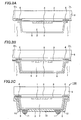
- Fig. 1A is a schematic plan view of a back surface of a semiconductor device 150 of the first embodiment of the invention
- Fig. 1B is a cross-sectional view of Fig. 1A along line X-X. It is noted that some components such as a protection layer 10, a pad electrode 4 and so on are omitted in Fig. 1A for convenience.
- a light receiving element 1 e.g. an element such as a CCD sensor, a CMOS sensor, or an illumination sensor
- a plurality of ball-shaped conductive terminals 11 is disposed on a back surface of the semiconductor substrate 2, and each of the conductive terminals 11 is electrically connected to the pad electrode 4 formed on the front surface of the semiconductor substrate 2 through a wiring layer 9.
- the wiring layer 9 and the conductive terminal 11 are formed on the back surface of the semiconductor substrate 2 except in a region overlapping the light receiving element 1 in a vertical direction (in a vertical direction relative to the sheet surface in Fig. 1A) and not disposed in a region overlapping the light receiving element 1.
- This structure may cause a case where an infrared ray entering from the light transparent substrate 6 toward the back surface of the semiconductor substrate 2 through the semiconductor substrate 2 or an infrared ray entering from the back surface of the semiconductor substrate 2 is diffusely reflected by the protection layer 10 made of a solder resist or the like or a bottom of the semiconductor device 150 (a surface contacting to the other components), and the light receiving element 1 receives the reflected light, thereby causing bad influence such as blurring an output image.
- an infrared ray absorbent such as, for example, a black pigment to the protection layer 10 covering the back surface of the semiconductor substrate 2.
- an infrared ray reaching the protection layer 10 is all absorbed, or even if not all absorbed only a slight amount of infrared ray is reflected, thereby minimizing the influence of diffuse reflection.
- an infrared ray absorption layer having the same infrared ray absorption effect as above may be provided in a region overlapping the light receiving element 1, in addition to the protection layer 10. It is preferable that the infrared ray absorbent added to the protection layer 10 or the infrared ray absorbent layer absorbs an infrared ray having a wavelength of about 700nm to 2500nm in its characteristics.
- the plurality of conductive terminals 11 may gather in a predetermined region on the back surface, depending on the size or position of the light receiving element 1, resulting in improper packaging of the semiconductor device 150 on a module such as a printed board due to its unbalance. Therefore, by providing a dummy electrode 50 on the back surface of the semiconductor substrate 2 according to needs, packaging strength is equalized, contributing to the improvement.
- FIGS. 2A to 3C are cross-sectional views of Figs. 1A along line X-X in manufacturing order.
- the semiconductor substrate 2 made of silicon (Si) or the like and formed with the light receiving element 1 on its front surface is prepared.
- a first insulation film 3 e.g. a silicon oxide film formed by a thermal oxidation method, a CVD method or the like
- a thickness of, for example, 2 ⁇ m is formed on the front surface of the semiconductor substrate 2 to have a thickness of, for example, 2 ⁇ m.
- a metal layer of aluminum (Al), copper (Cu), or the like is formed by a sputtering method, a plating method, or the other deposition method, and the metal layer is etched using a photoresist layer (not shown) as a mask to form the pad electrode 4 having a thickness of, for example, 1 ⁇ m on the first insulation film 3.
- the pad electrode 4 is an external connection electrode electrically connected to the light receiving element 1 or the surrounding elements.
- a passivation film e.g. a silicon nitride film formed by a CVD method (not shown) is formed on the front surface of the semiconductor substrate 2, covering a portion of the pad electrode 4.
- the light transparent substrate 6 is attached on the front surface of the semiconductor substrate 2 including on the pad electrode 4 with a resin layer 5 made of epoxy resin or the like interposed therebetween.
- the light transparent substrate 6 is made of a transparent or semitransparent material such as glass or quartz and has light transmission characteristics.
- back-grinding is performed to the back surface of the semiconductor substrate 2 to thin the semiconductor substrate 2 to a thickness of, for example, about 100 ⁇ m.
- the grinding process is not needed depending on applications or specifications of an end-product and the initial thickness of the prepared semiconductor substrate 2.
- this exposed portion is called an opening 7.
- this opening 7 has a tapered shape of which the diameter is reducing from the back surface toward the front surface of the semiconductor substrate 2. It is also possible to form the opening 7 in a straight shape by etching so that the side surface of the semiconductor substrate 2 is vertical to a main surface of the light transparent substrate 6 although not shown in the figure.
- a second insulation film 8 is formed on the side surface and back surface of the semiconductor substrate 2 including in the opening 7.
- This second insulation film is a silicon oxide film or a silicon nitride film formed by, for example, a plasma CVD method.
- the first insulation film 3 and the second insulation film 8 are selectively etched using a photoresist layer (not shown) as a mask. By this etching, the first insulation film 3 and the second insulation film 8 formed in a region from on a portion of the pad electrode 4 to a dicing line DL are removed to expose the portion of the pad electrode 4 at a bottom of the opening 7.
- a metal layer made of aluminum (Al), copper (Cu) or the like that is to be the wiring layer 9 is formed by a sputtering method, a plating method, or the other deposition method. Then, this is etched using a photoresist layer (not shown) as a mask to form the wiring layer 9 having a thickness of, for example, 1 ⁇ m on the portion of the pad electrode 4 and the second insulation film 8.
- the protection layer 10 made of a resist material such as a solder resist is formed on the back surface of the semiconductor substrate 2 including on the wiring layer 9. Then, as shown in Fig. 3C, an opening is formed in a predetermined region of the protection layer 10, an electrode connection layer (not shown) made of nickel, gold or the like is formed on the wiring layer 9 exposed in the opening, and the ball-shaped conductive terminal 11 made of solder, aluminum, gold or the like is formed thereon.
- the protection layer 10 is made of a negative resist material, the protection layer 10 in a region irradiated with light is left as it is, and the protection layer 10 in a region irradiated with no light is removed to form the opening. Wiring from the pad electrode 4 on the front surface of the semiconductor substrate 2 to the conductive terminal 11 formed on the back surface along the sidewall is thus realized in this manner.
- the dummy electrode 50 may be also formed in the process of forming the conductive terminal 11 according to needs as described above.
- an opening is formed in a predetermined region of the protection layer 10 where the dummy electrode 50 is to be formed, and the ball-shaped dummy electrode 50 made of solder, aluminum, gold, nickel or the like is formed in the opening.
- dicing is performed along the dicing line DL that is a boundary of a number of semiconductor devices into individual separated semiconductor devices 150.
- the chip size package type semiconductor device having the light receiving element 1 is completed.
- the wiring layer 9 and the conductive terminal 11 are not disposed in the region overlapping the light receiving element 1 on the back surface of the semiconductor substrate 2, the conventional problem of reflection of the patterns of the wiring layer 9 and the conductive terminal 11 on an output image is prevented. Furthermore, since this effect is obtained by this changing of the positions of the wiring layer 9 and the conductive terminal 11, the number of manufacturing processes does not increase, compared with that of the conventional manufacturing processes. Furthermore, the influence of diffuse reflection is prevented by mixing the infrared ray absorbent material in the protection layer 10 or additionally providing the infrared ray absorbent layer.
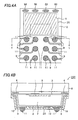
- Fig. 4A is a plan view of a back surface of a semiconductor device 200 of the second embodiment of the invention
- Fig. 4B is a cross-sectional view of Fig. 4A along line Y-Y. It is noted that the same numerals are given to the same components as those of the first embodiment and the description thereof will be omitted.
- the second embodiment is the same as the first embodiment in that some components such as the protection layer 10 are omitted in Fig. 4A for convenience, and in that the wiring layer 9 and the conductive terminal 11 are not disposed in the region overlapping the light receiving element 1 on the back surface of the semiconductor substrate 2.
- the semiconductor device 200 of the second embodiment has a feature that a reflection layer 20 made of a metal material, for example, aluminum, gold, silver, copper or the like is formed uniformly planar on the back surface of the semiconductor substrate 2 at least in the region overlapping the light receiving element 1, as shown in Figs. 4A and 4B.
- the reflection layer 20 is a layer having a function of reflecting an infrared ray entering from the light transparent substrate 6 toward the back surface of the semiconductor substrate 2 through the semiconductor substrate 2 or an infrared ray from the back surface of the semiconductor substrate 2 without further transmitting it therethrough, and its material or thickness is not particularly limited as long as it has such a function.
- the reflection layer 20 is 0.1 to 2 ⁇ m in thickness, for example.
- this reflection layer 20 may be made of the same material as that of the wiring layer 9 and formed in the process of forming the wiring layer 9.
- a metal layer made of aluminum, copper or the like is formed by a sputtering method, a plating method, or the other deposition method such as shown in Fig. 3B. Then, patterning is performed to this metal layer to form the reflection layer 20 at the same time when the patterning is performed to the metal layer to form the wiring layer 9.
- an infrared ray entering from the light transparent substrate 6 and reaching the reflection layer 20 is reflected by this reflection layer 20 toward the light receiving element 1.
- this provides an advantage that light strength of an infrared ray entering the light receiving element 1 increases to enhance the contrast of the output image.
- the reflection layer 20 is formed in the process of forming the wiring layer 9, the number of the manufacturing processes does not increase, compared with the first embodiment.
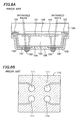
- the invention may be also applied to a so-called penetrating electrode type semiconductor device where a via hole is formed penetrating the semiconductor substrate 2 from its front surface to its back surface in a position corresponding to the pad electrode 4, a penetrating electrode 21 is formed in the via hole, and a wiring layer 22 is formed on the back surface of the semiconductor substrate 2, being electrically connected to the penetrating electrode'21.
- Fig. 5B is a cross-sectional view of Fig. 5A along line Z-Z, where the same numerals are given to the same components as those of the above described semiconductor device and the description thereof will be omitted.
- barrier metal layer made of metal such as, for example, a titanium (Ti) layer, a titanium oxide (TiO 2 ) layer, a titanium nitride (TiN) layer, or a tantalum nitride (TaN) layer.
- This penetrating electrode type semiconductor device is formed by the following manufacturing processes, for example. First, the semiconductor substrate 2 formed with the pad electrode 4 with the light receiving element 1 and the first insulation film 3 interposed therebetween is formed. Then, the via hole is formed, penetrating the semiconductor substrate 2 in a position corresponding to the pad electrode 4. A second insulation film 8a is then formed, covering a sidewall of the via hole and the back surface of the semiconductor substrate 2. The second insulation film 8a on a bottom of the via hole is then removed, and the barrier metal layer 23 is formed in the via hole. The penetrating electrode 21 made of metal such as copper is then formed in the via hole by, for example, an electrolytic plating method.
- the wiring layer 22 is formed on the back surface of the semiconductor substrate 2 except in a region overlapping the light receiving element 1 by patterning, being electrically connected to the penetrating electrode 21.
- the ball-shaped conductive terminal 11 and the protection layer 10 are then formed. It is noted that the above described processes are an example of the method of manufacturing the penetrating electrode type semiconductor device, and the invention is not limited to this processes.
- the reflection layer may be formed at least in the region overlapping the light receiving element 1 in the penetrating electrode type semiconductor device shown in Figs. 5A and 5B.
- the invention may be applied to the LGA (land grid array) type semiconductor device.
- the embodiments above achieve prevention of reflection of the patterns of the conductive terminal and the wiring layer formed on the back surface of the semiconductor substrate on an output image without making the manufacturing process complex.
Applications Claiming Priority (1)
| Application Number | Priority Date | Filing Date | Title |
|---|---|---|---|
| JP2005361707A JP2007165696A (ja) | 2005-12-15 | 2005-12-15 | 半導体装置及びその製造方法 |
Publications (2)
| Publication Number | Publication Date |
|---|---|
| EP1798768A2 true EP1798768A2 (de) | 2007-06-20 |
| EP1798768A3 EP1798768A3 (de) | 2009-07-08 |
Family
ID=37858971
Family Applications (1)
| Application Number | Title | Priority Date | Filing Date |
|---|---|---|---|
| EP06026027A Withdrawn EP1798768A3 (de) | 2005-12-15 | 2006-12-15 | Halbleiterbauelement und sein Herstellungsverfahren |
Country Status (7)
| Country | Link |
|---|---|
| US (1) | US7633133B2 (de) |
| EP (1) | EP1798768A3 (de) |
| JP (1) | JP2007165696A (de) |
| KR (1) | KR100840070B1 (de) |
| CN (1) | CN1983612B (de) |
| SG (1) | SG133536A1 (de) |
| TW (1) | TWI331396B (de) |
Families Citing this family (21)
| Publication number | Priority date | Publication date | Assignee | Title |
|---|---|---|---|---|
| JP5010244B2 (ja) * | 2005-12-15 | 2012-08-29 | オンセミコンダクター・トレーディング・リミテッド | 半導体装置 |
| JP5238929B2 (ja) * | 2006-09-11 | 2013-07-17 | セミコンダクター・コンポーネンツ・インダストリーズ・リミテッド・ライアビリティ・カンパニー | 半導体装置及びその製造方法 |
| US7679167B2 (en) * | 2007-01-08 | 2010-03-16 | Visera Technologies Company, Limited | Electronic assembly for image sensor device and fabrication method thereof |
| JP5301108B2 (ja) * | 2007-04-20 | 2013-09-25 | セミコンダクター・コンポーネンツ・インダストリーズ・リミテッド・ライアビリティ・カンパニー | 半導体装置 |
| JP2009032929A (ja) * | 2007-07-27 | 2009-02-12 | Sanyo Electric Co Ltd | 半導体装置及びその製造方法 |
| JP2009099591A (ja) * | 2007-10-12 | 2009-05-07 | Toshiba Corp | 固体撮像素子及びその製造方法 |
| JP5498684B2 (ja) * | 2008-11-07 | 2014-05-21 | ラピスセミコンダクタ株式会社 | 半導体モジュール及びその製造方法 |
| JP5427394B2 (ja) | 2008-11-21 | 2014-02-26 | セミコンダクター・コンポーネンツ・インダストリーズ・リミテッド・ライアビリティ・カンパニー | 半導体装置の製造方法 |
| CN101419952B (zh) * | 2008-12-03 | 2010-09-15 | 晶方半导体科技(苏州)有限公司 | 晶圆级芯片封装方法及封装结构 |
| JP5150566B2 (ja) * | 2009-06-22 | 2013-02-20 | 株式会社東芝 | 半導体装置およびカメラモジュール |
| JP5757614B2 (ja) * | 2010-03-05 | 2015-07-29 | 国立大学法人九州工業大学 | 撮像素子 |
| JP2013084722A (ja) * | 2011-10-07 | 2013-05-09 | Toshiba Corp | 固体撮像装置および固体撮像装置の製造方法 |
| JP6215612B2 (ja) | 2013-08-07 | 2017-10-18 | ソニーセミコンダクタソリューションズ株式会社 | 発光素子、発光素子ウェーハ及び電子機器 |
| JP6279857B2 (ja) * | 2013-08-29 | 2018-02-14 | 京セラ株式会社 | 電子装置、多数個取り枠体および多数個取り電子装置 |
| JP6642002B2 (ja) * | 2013-11-06 | 2020-02-05 | ソニー株式会社 | 半導体装置、固体撮像素子、および電子機器 |
| JP6658782B2 (ja) * | 2013-12-19 | 2020-03-04 | ソニー株式会社 | 半導体装置の製造方法 |
| JP6300029B2 (ja) | 2014-01-27 | 2018-03-28 | ソニー株式会社 | 撮像素子、製造装置、製造方法 |
| JP2016001633A (ja) | 2014-06-11 | 2016-01-07 | ソニー株式会社 | 固体撮像素子、および電子装置 |
| TWI585870B (zh) * | 2015-05-20 | 2017-06-01 | 精材科技股份有限公司 | 晶片封裝體及其製造方法 |
| JP7266961B2 (ja) | 2015-12-31 | 2023-05-01 | 晶元光電股▲ふん▼有限公司 | 発光装置 |
| JP2018133392A (ja) * | 2017-02-14 | 2018-08-23 | キヤノン株式会社 | 光電変換装置 |
Citations (3)
| Publication number | Priority date | Publication date | Assignee | Title |
|---|---|---|---|---|
| US20020019069A1 (en) * | 2000-07-11 | 2002-02-14 | Seiko Epson Corporation | Optical element and method of manufacturing the same, and electronic instrument |
| US20040016983A1 (en) * | 2002-07-17 | 2004-01-29 | Takeshi Misawa | Semiconductor device and method for manufacturing the same |
| US20050009238A1 (en) * | 2003-02-06 | 2005-01-13 | Mitsuru Okigawa | Semiconductor integrated device including support substrate fastened using resin, and manufacturing method thereof |
Family Cites Families (33)
| Publication number | Priority date | Publication date | Assignee | Title |
|---|---|---|---|---|
| JPH0521698A (ja) | 1991-07-11 | 1993-01-29 | Mitsubishi Electric Corp | 半導体装置 |
| US5656819A (en) * | 1994-11-16 | 1997-08-12 | Sandia Corporation | Pulsed ion beam source |
| JP2674545B2 (ja) | 1995-01-20 | 1997-11-12 | 日本電気株式会社 | 赤外線検出器及びその駆動方法 |
| US5804827A (en) * | 1995-10-27 | 1998-09-08 | Nikon Corporation | Infrared ray detection device and solid-state imaging apparatus |
| JPH09321333A (ja) | 1996-05-24 | 1997-12-12 | Nikon Corp | 赤外線検出素子 |
| US5929440A (en) * | 1996-10-25 | 1999-07-27 | Hypres, Inc. | Electromagnetic radiation detector |
| US5981314A (en) * | 1996-10-31 | 1999-11-09 | Amkor Technology, Inc. | Near chip size integrated circuit package |
| US5973337A (en) * | 1997-08-25 | 1999-10-26 | Motorola, Inc. | Ball grid device with optically transmissive coating |
| JPH11167154A (ja) * | 1997-12-03 | 1999-06-22 | Olympus Optical Co Ltd | フレキシブルプリント基板 |
| IL123207A0 (en) * | 1998-02-06 | 1998-09-24 | Shellcase Ltd | Integrated circuit device |
| JP2000349238A (ja) | 1999-06-04 | 2000-12-15 | Seiko Epson Corp | 半導体装置 |
| US6326689B1 (en) * | 1999-07-26 | 2001-12-04 | Stmicroelectronics, Inc. | Backside contact for touchchip |
| US6465786B1 (en) * | 1999-09-01 | 2002-10-15 | Micron Technology, Inc. | Deep infrared photodiode for a CMOS imager |
| JP2001085652A (ja) | 1999-09-09 | 2001-03-30 | Sony Corp | 赤外線用ccd撮像素子パッケージ |
| JP3632558B2 (ja) * | 1999-09-17 | 2005-03-23 | 日立化成工業株式会社 | 封止用エポキシ樹脂組成物及び電子部品装置 |
| US6455774B1 (en) * | 1999-12-08 | 2002-09-24 | Amkor Technology, Inc. | Molded image sensor package |
| JP3409848B2 (ja) * | 2000-08-29 | 2003-05-26 | 日本電気株式会社 | 熱型赤外線検出器 |
| USRE42281E1 (en) * | 2000-09-11 | 2011-04-12 | Hamamatsu Photonics K.K. | Scintillator panel, radiation image sensor and methods of producing them |
| KR20020048716A (ko) * | 2000-12-18 | 2002-06-24 | 박종섭 | 기판 뒷면에 반사층을 구비하는 이미지 센서 및 그 제조방법 |
| JP3910817B2 (ja) * | 2000-12-19 | 2007-04-25 | ユーディナデバイス株式会社 | 半導体受光装置 |
| US20040108588A1 (en) * | 2002-09-24 | 2004-06-10 | Cookson Electronics, Inc. | Package for microchips |
| US7033664B2 (en) * | 2002-10-22 | 2006-04-25 | Tessera Technologies Hungary Kft | Methods for producing packaged integrated circuit devices and packaged integrated circuit devices produced thereby |
| JP5030360B2 (ja) * | 2002-12-25 | 2012-09-19 | オリンパス株式会社 | 固体撮像装置の製造方法 |
| JP2004319530A (ja) * | 2003-02-28 | 2004-11-11 | Sanyo Electric Co Ltd | 光半導体装置およびその製造方法 |
| TWI229890B (en) * | 2003-04-24 | 2005-03-21 | Sanyo Electric Co | Semiconductor device and method of manufacturing same |
| JP2007528120A (ja) | 2003-07-03 | 2007-10-04 | テッセラ テクノロジーズ ハンガリー コルラートルト フェレロェセーギュー タールシャシャーグ | 集積回路装置をパッケージングする方法及び装置 |
| JP4401181B2 (ja) * | 2003-08-06 | 2010-01-20 | 三洋電機株式会社 | 半導体装置及びその製造方法 |
| US7329861B2 (en) * | 2003-10-14 | 2008-02-12 | Micron Technology, Inc. | Integrally packaged imaging module |
| US7332408B2 (en) * | 2004-06-28 | 2008-02-19 | Micron Technology, Inc. | Isolation trenches for memory devices |
| JP2006093367A (ja) | 2004-09-24 | 2006-04-06 | Sanyo Electric Co Ltd | 半導体装置の製造方法 |
| JP5010244B2 (ja) * | 2005-12-15 | 2012-08-29 | オンセミコンダクター・トレーディング・リミテッド | 半導体装置 |
| JP5301108B2 (ja) * | 2007-04-20 | 2013-09-25 | セミコンダクター・コンポーネンツ・インダストリーズ・リミテッド・ライアビリティ・カンパニー | 半導体装置 |
| JP2009032929A (ja) * | 2007-07-27 | 2009-02-12 | Sanyo Electric Co Ltd | 半導体装置及びその製造方法 |
-
2005
- 2005-12-15 JP JP2005361707A patent/JP2007165696A/ja not_active Withdrawn
-
2006
- 2006-12-06 TW TW095145300A patent/TWI331396B/zh not_active IP Right Cessation
- 2006-12-08 CN CN2006101667094A patent/CN1983612B/zh not_active Expired - Fee Related
- 2006-12-14 KR KR1020060127630A patent/KR100840070B1/ko not_active IP Right Cessation
- 2006-12-15 US US11/639,411 patent/US7633133B2/en active Active
- 2006-12-15 SG SG200608734-0A patent/SG133536A1/en unknown
- 2006-12-15 EP EP06026027A patent/EP1798768A3/de not_active Withdrawn
Patent Citations (3)
| Publication number | Priority date | Publication date | Assignee | Title |
|---|---|---|---|---|
| US20020019069A1 (en) * | 2000-07-11 | 2002-02-14 | Seiko Epson Corporation | Optical element and method of manufacturing the same, and electronic instrument |
| US20040016983A1 (en) * | 2002-07-17 | 2004-01-29 | Takeshi Misawa | Semiconductor device and method for manufacturing the same |
| US20050009238A1 (en) * | 2003-02-06 | 2005-01-13 | Mitsuru Okigawa | Semiconductor integrated device including support substrate fastened using resin, and manufacturing method thereof |
Also Published As
| Publication number | Publication date |
|---|---|
| US7633133B2 (en) | 2009-12-15 |
| CN1983612A (zh) | 2007-06-20 |
| SG133536A1 (en) | 2007-07-30 |
| KR20070064268A (ko) | 2007-06-20 |
| EP1798768A3 (de) | 2009-07-08 |
| TWI331396B (en) | 2010-10-01 |
| US20070145590A1 (en) | 2007-06-28 |
| JP2007165696A (ja) | 2007-06-28 |
| CN1983612B (zh) | 2010-07-21 |
| KR100840070B1 (ko) | 2008-06-19 |
| TW200731521A (en) | 2007-08-16 |
Similar Documents
| Publication | Publication Date | Title |
|---|---|---|
| US7633133B2 (en) | Semiconductor device and manufacturing method of the same | |
| US7986021B2 (en) | Semiconductor device | |
| US8102039B2 (en) | Semiconductor device and manufacturing method thereof | |
| US8174090B2 (en) | Packaging structure | |
| US7365364B2 (en) | Sensor semiconductor device with sensor chip | |
| US8766408B2 (en) | Semiconductor device and manufacturing method thereof | |
| US7576402B2 (en) | Semiconductor device, method of manufacturing the same, and camera module | |
| US7271024B2 (en) | Method for fabricating sensor semiconductor device | |
| US7589388B2 (en) | Semiconductor device and method of manufacturing the same | |
| US7446307B2 (en) | Sensor semiconductor device and fabrication method of the sensor semiconductor device | |
| US20190096866A1 (en) | Semiconductor package and manufacturing method thereof | |
| US7397134B2 (en) | Semiconductor device mounted on and electrically connected to circuit board | |
| US8053852B2 (en) | Light sensor receiving light from backside | |
| JP3614840B2 (ja) | 半導体装置 | |
| KR100629467B1 (ko) | 이미지 센서용 패키지 | |
| EP1879230A1 (de) | Halbleitervorrichtung und Herstellungsverfahren dazu | |
| KR20020082294A (ko) | 반도체패키지 및 그 제조 방법 |
Legal Events
| Date | Code | Title | Description |
|---|---|---|---|
| PUAI | Public reference made under article 153(3) epc to a published international application that has entered the european phase |
Free format text: ORIGINAL CODE: 0009012 |
|
| AK | Designated contracting states |
Kind code of ref document: A2 Designated state(s): AT BE BG CH CY CZ DE DK EE ES FI FR GB GR HU IE IS IT LI LT LU LV MC NL PL PT RO SE SI SK TR |
|
| AX | Request for extension of the european patent |
Extension state: AL BA HR MK YU |
|
| PUAL | Search report despatched |
Free format text: ORIGINAL CODE: 0009013 |
|
| AK | Designated contracting states |
Kind code of ref document: A3 Designated state(s): AT BE BG CH CY CZ DE DK EE ES FI FR GB GR HU IE IS IT LI LT LU LV MC NL PL PT RO SE SI SK TR |
|
| AX | Request for extension of the european patent |
Extension state: AL BA HR MK RS |
|
| AKX | Designation fees paid | ||
| STAA | Information on the status of an ep patent application or granted ep patent |
Free format text: STATUS: THE APPLICATION IS DEEMED TO BE WITHDRAWN |
|
| 18D | Application deemed to be withdrawn |
Effective date: 20100109 |
|
| REG | Reference to a national code |
Ref country code: DE Ref legal event code: 8566 |