EP1775777A2 - Structure extérieure d'un système photovoltaïque de production d'energie - Google Patents
Structure extérieure d'un système photovoltaïque de production d'energie Download PDFInfo
- Publication number
- EP1775777A2 EP1775777A2 EP06020430A EP06020430A EP1775777A2 EP 1775777 A2 EP1775777 A2 EP 1775777A2 EP 06020430 A EP06020430 A EP 06020430A EP 06020430 A EP06020430 A EP 06020430A EP 1775777 A2 EP1775777 A2 EP 1775777A2
- Authority
- EP
- European Patent Office
- Prior art keywords
- fixing
- power generation
- photovoltaic power
- outer surrounding
- portions
- Prior art date
- Legal status (The legal status is an assumption and is not a legal conclusion. Google has not performed a legal analysis and makes no representation as to the accuracy of the status listed.)
- Withdrawn
Links
- 238000010248 power generation Methods 0.000 title claims abstract description 136
- 239000000463 material Substances 0.000 claims abstract description 59
- 229910000831 Steel Inorganic materials 0.000 claims description 69
- 239000010959 steel Substances 0.000 claims description 69
- XLYOFNOQVPJJNP-UHFFFAOYSA-N water Substances O XLYOFNOQVPJJNP-UHFFFAOYSA-N 0.000 claims description 20
- 239000013013 elastic material Substances 0.000 claims description 5
- 238000009434 installation Methods 0.000 abstract description 18
- 238000003780 insertion Methods 0.000 abstract description 2
- 230000037431 insertion Effects 0.000 abstract description 2
- 230000007547 defect Effects 0.000 description 7
- 238000000034 method Methods 0.000 description 7
- 230000007797 corrosion Effects 0.000 description 5
- 238000005260 corrosion Methods 0.000 description 5
- 230000002093 peripheral effect Effects 0.000 description 5
- 230000000694 effects Effects 0.000 description 4
- 229910052751 metal Inorganic materials 0.000 description 4
- 239000002184 metal Substances 0.000 description 4
- 150000002739 metals Chemical class 0.000 description 4
- PPBRXRYQALVLMV-UHFFFAOYSA-N Styrene Chemical compound C=CC1=CC=CC=C1 PPBRXRYQALVLMV-UHFFFAOYSA-N 0.000 description 2
- 238000004826 seaming Methods 0.000 description 2
- 244000043261 Hevea brasiliensis Species 0.000 description 1
- 239000000853 adhesive Substances 0.000 description 1
- 150000001336 alkenes Chemical class 0.000 description 1
- 238000010276 construction Methods 0.000 description 1
- 230000006866 deterioration Effects 0.000 description 1
- 150000001993 dienes Chemical class 0.000 description 1
- 229920003052 natural elastomer Polymers 0.000 description 1
- 229920001194 natural rubber Polymers 0.000 description 1
- JRZJOMJEPLMPRA-UHFFFAOYSA-N olefin Natural products CCCCCCCC=C JRZJOMJEPLMPRA-UHFFFAOYSA-N 0.000 description 1
- 239000003566 sealing material Substances 0.000 description 1
- 150000003377 silicon compounds Chemical class 0.000 description 1
- 239000010454 slate Substances 0.000 description 1
- 229920003051 synthetic elastomer Polymers 0.000 description 1
- 239000005061 synthetic rubber Substances 0.000 description 1
- 229920002725 thermoplastic elastomer Polymers 0.000 description 1
Images


Classifications
-
- H—ELECTRICITY
- H02—GENERATION; CONVERSION OR DISTRIBUTION OF ELECTRIC POWER
- H02S—GENERATION OF ELECTRIC POWER BY CONVERSION OF INFRARED RADIATION, VISIBLE LIGHT OR ULTRAVIOLET LIGHT, e.g. USING PHOTOVOLTAIC [PV] MODULES
- H02S20/00—Supporting structures for PV modules
- H02S20/20—Supporting structures directly fixed to an immovable object
- H02S20/22—Supporting structures directly fixed to an immovable object specially adapted for buildings
- H02S20/23—Supporting structures directly fixed to an immovable object specially adapted for buildings specially adapted for roof structures
-
- E—FIXED CONSTRUCTIONS
- E04—BUILDING
- E04F—FINISHING WORK ON BUILDINGS, e.g. STAIRS, FLOORS
- E04F13/00—Coverings or linings, e.g. for walls or ceilings
- E04F13/07—Coverings or linings, e.g. for walls or ceilings composed of covering or lining elements; Sub-structures therefor; Fastening means therefor
- E04F13/08—Coverings or linings, e.g. for walls or ceilings composed of covering or lining elements; Sub-structures therefor; Fastening means therefor composed of a plurality of similar covering or lining elements
- E04F13/0801—Separate fastening elements
- E04F13/0803—Separate fastening elements with load-supporting elongated furring elements between wall and covering elements
- E04F13/081—Separate fastening elements with load-supporting elongated furring elements between wall and covering elements with additional fastening elements between furring elements and covering elements
- E04F13/0814—Separate fastening elements with load-supporting elongated furring elements between wall and covering elements with additional fastening elements between furring elements and covering elements fixed by means of clamping action
-
- F—MECHANICAL ENGINEERING; LIGHTING; HEATING; WEAPONS; BLASTING
- F24—HEATING; RANGES; VENTILATING
- F24S—SOLAR HEAT COLLECTORS; SOLAR HEAT SYSTEMS
- F24S25/00—Arrangement of stationary mountings or supports for solar heat collector modules
- F24S25/30—Arrangement of stationary mountings or supports for solar heat collector modules using elongate rigid mounting elements extending substantially along the supporting surface, e.g. for covering buildings with solar heat collectors
- F24S25/33—Arrangement of stationary mountings or supports for solar heat collector modules using elongate rigid mounting elements extending substantially along the supporting surface, e.g. for covering buildings with solar heat collectors forming substantially planar assemblies, e.g. of coplanar or stacked profiles
- F24S25/35—Arrangement of stationary mountings or supports for solar heat collector modules using elongate rigid mounting elements extending substantially along the supporting surface, e.g. for covering buildings with solar heat collectors forming substantially planar assemblies, e.g. of coplanar or stacked profiles by means of profiles with a cross-section defining separate supporting portions for adjacent modules
-
- F—MECHANICAL ENGINEERING; LIGHTING; HEATING; WEAPONS; BLASTING
- F24—HEATING; RANGES; VENTILATING
- F24S—SOLAR HEAT COLLECTORS; SOLAR HEAT SYSTEMS
- F24S25/00—Arrangement of stationary mountings or supports for solar heat collector modules
- F24S25/60—Fixation means, e.g. fasteners, specially adapted for supporting solar heat collector modules
- F24S25/61—Fixation means, e.g. fasteners, specially adapted for supporting solar heat collector modules for fixing to the ground or to building structures
- F24S25/615—Fixation means, e.g. fasteners, specially adapted for supporting solar heat collector modules for fixing to the ground or to building structures for fixing to protruding parts of buildings, e.g. to corrugations or to standing seams
-
- F—MECHANICAL ENGINEERING; LIGHTING; HEATING; WEAPONS; BLASTING
- F24—HEATING; RANGES; VENTILATING
- F24S—SOLAR HEAT COLLECTORS; SOLAR HEAT SYSTEMS
- F24S25/00—Arrangement of stationary mountings or supports for solar heat collector modules
- F24S25/60—Fixation means, e.g. fasteners, specially adapted for supporting solar heat collector modules
- F24S25/63—Fixation means, e.g. fasteners, specially adapted for supporting solar heat collector modules for fixing modules or their peripheral frames to supporting elements
- F24S25/634—Clamps; Clips
-
- F—MECHANICAL ENGINEERING; LIGHTING; HEATING; WEAPONS; BLASTING
- F24—HEATING; RANGES; VENTILATING
- F24S—SOLAR HEAT COLLECTORS; SOLAR HEAT SYSTEMS
- F24S20/00—Solar heat collectors specially adapted for particular uses or environments
- F24S20/60—Solar heat collectors integrated in fixed constructions, e.g. in buildings
- F24S20/67—Solar heat collectors integrated in fixed constructions, e.g. in buildings in the form of roof constructions
-
- F—MECHANICAL ENGINEERING; LIGHTING; HEATING; WEAPONS; BLASTING
- F24—HEATING; RANGES; VENTILATING
- F24S—SOLAR HEAT COLLECTORS; SOLAR HEAT SYSTEMS
- F24S25/00—Arrangement of stationary mountings or supports for solar heat collector modules
- F24S2025/01—Special support components; Methods of use
- F24S2025/021—Sealing means between support elements and mounting surface
-
- F—MECHANICAL ENGINEERING; LIGHTING; HEATING; WEAPONS; BLASTING
- F24—HEATING; RANGES; VENTILATING
- F24S—SOLAR HEAT COLLECTORS; SOLAR HEAT SYSTEMS
- F24S25/00—Arrangement of stationary mountings or supports for solar heat collector modules
- F24S25/60—Fixation means, e.g. fasteners, specially adapted for supporting solar heat collector modules
- F24S2025/6003—Fixation means, e.g. fasteners, specially adapted for supporting solar heat collector modules by clamping
-
- Y—GENERAL TAGGING OF NEW TECHNOLOGICAL DEVELOPMENTS; GENERAL TAGGING OF CROSS-SECTIONAL TECHNOLOGIES SPANNING OVER SEVERAL SECTIONS OF THE IPC; TECHNICAL SUBJECTS COVERED BY FORMER USPC CROSS-REFERENCE ART COLLECTIONS [XRACs] AND DIGESTS
- Y02—TECHNOLOGIES OR APPLICATIONS FOR MITIGATION OR ADAPTATION AGAINST CLIMATE CHANGE
- Y02B—CLIMATE CHANGE MITIGATION TECHNOLOGIES RELATED TO BUILDINGS, e.g. HOUSING, HOUSE APPLIANCES OR RELATED END-USER APPLICATIONS
- Y02B10/00—Integration of renewable energy sources in buildings
- Y02B10/10—Photovoltaic [PV]
-
- Y—GENERAL TAGGING OF NEW TECHNOLOGICAL DEVELOPMENTS; GENERAL TAGGING OF CROSS-SECTIONAL TECHNOLOGIES SPANNING OVER SEVERAL SECTIONS OF THE IPC; TECHNICAL SUBJECTS COVERED BY FORMER USPC CROSS-REFERENCE ART COLLECTIONS [XRACs] AND DIGESTS
- Y02—TECHNOLOGIES OR APPLICATIONS FOR MITIGATION OR ADAPTATION AGAINST CLIMATE CHANGE
- Y02B—CLIMATE CHANGE MITIGATION TECHNOLOGIES RELATED TO BUILDINGS, e.g. HOUSING, HOUSE APPLIANCES OR RELATED END-USER APPLICATIONS
- Y02B10/00—Integration of renewable energy sources in buildings
- Y02B10/20—Solar thermal
-
- Y—GENERAL TAGGING OF NEW TECHNOLOGICAL DEVELOPMENTS; GENERAL TAGGING OF CROSS-SECTIONAL TECHNOLOGIES SPANNING OVER SEVERAL SECTIONS OF THE IPC; TECHNICAL SUBJECTS COVERED BY FORMER USPC CROSS-REFERENCE ART COLLECTIONS [XRACs] AND DIGESTS
- Y02—TECHNOLOGIES OR APPLICATIONS FOR MITIGATION OR ADAPTATION AGAINST CLIMATE CHANGE
- Y02E—REDUCTION OF GREENHOUSE GAS [GHG] EMISSIONS, RELATED TO ENERGY GENERATION, TRANSMISSION OR DISTRIBUTION
- Y02E10/00—Energy generation through renewable energy sources
- Y02E10/40—Solar thermal energy, e.g. solar towers
- Y02E10/47—Mountings or tracking
-
- Y—GENERAL TAGGING OF NEW TECHNOLOGICAL DEVELOPMENTS; GENERAL TAGGING OF CROSS-SECTIONAL TECHNOLOGIES SPANNING OVER SEVERAL SECTIONS OF THE IPC; TECHNICAL SUBJECTS COVERED BY FORMER USPC CROSS-REFERENCE ART COLLECTIONS [XRACs] AND DIGESTS
- Y02—TECHNOLOGIES OR APPLICATIONS FOR MITIGATION OR ADAPTATION AGAINST CLIMATE CHANGE
- Y02E—REDUCTION OF GREENHOUSE GAS [GHG] EMISSIONS, RELATED TO ENERGY GENERATION, TRANSMISSION OR DISTRIBUTION
- Y02E10/00—Energy generation through renewable energy sources
- Y02E10/50—Photovoltaic [PV] energy
Definitions
- the present invention relates to an outer surrounding structure of a photovoltaic power generation for attaching a photovoltaic power generation panel to an outer surrounding body such as a roof, a wall or the like of a building.
- a photovoltaic power generation system is constituted by photovoltaic power generation panels provided with solar cells converting an energy of solar beam into an electric power, a connection box getting dc wires from a plurality of photovoltaic power generation panels together, and a power conditioner converting a dc power supplied from the connection box into an ac power and controlling a frequency, a voltage, a current, a phase, an output quality and the like.
- a plurality of photovoltaic power generation panels of the photovoltaic power generation system are generally arranged on the outer surrounding body such as the roof, the wall or the like of the building in a state in which the photovoltaic power generation panels are wired in series.
- a roof fixing apparatus for example, refer to Japanese unexamined patent publication No.2003-96987
- a base table which is provided with a linear rail groove having an opening portion for locking and is fixed to a roof material such as a slate or the like, a roof structure material and a balk by a screw, a nail or the like
- a pressing member for pressure fixing a peripheral edge portion of a rood installation body arranged on the base table, and a fastening member movable along the rail groove and provided for fixing the pressing member while engaging with the opening portion for locking
- a roof fixing apparatus for example, refer to Japanese unexamined patent publication No.2003-253826
- the method of installing the photovoltaic power generation panel using the fixing apparatus mentioned above is advantageous in the case that the photovoltaic power generation system is constructed in the existing building by installing the photovoltaic power generation panel later in the outer surrounding body such as the existing roof or wall or the like.
- the fixing apparatus is directly fixed to the outer surrounding body, the base material or the like by the screw, the nail or the like, or the fixing apparatus is directly fixed to the outer surrounding body in such a manner as to pinch the convex portion or the like of the outer surrounding body by the clamp pieces of the fixing apparatus.
- the building itself, the outer surrounding body or the like is vibrated due to a swing caused by a peripheral environment, a wind or the like, whereby a deformation is generated in the position where the fixing apparatus and the outer surrounding body are brought into contact with each other, the position where the nail or the like is driven in the outer surrounding body, or the like. Accordingly, there is generated a defect that the weathering performance is further deteriorated. Particularly, in the case that the fixing apparatus is directly fixed to the base material such as the balk, the roofing board or the like by the screw, the nail or the like, there is a defect that a risk of the leak generation is very high.
- a horizontally roofing roof plate (for example, refer to Japanese unexamined patent publication No.10-72910 , Figs. 12 to 18) which has, for example, an upper end engagement portion and a lower end engagement portion, and in which a solar cell element is fixed to an upper surface of a roof plate base material by a sealing material and a terminal box is provided in a lower surface of the roof plate base material.
- the photovoltaic power generation panel formed to be integral with the outer surrounding body since it is necessary to pierce a hole portion for wiring through at least the outer surrounding body itself in each of the roof materials for putting a wiring cable for inputting and outputting an electric power converted by the solar battery therethrough to an indoor side, in the photovoltaic power generation panel formed to be integral with the outer surrounding body, the leak is generated due to the rain water intrusion from the hole portion for wiring, so that there is generated a defect that the weathering performance is deteriorated. Further, since the building itself, the outer surrounding body and the like are vibrated due to the swing caused by the peripheral environment, the wind or the like, the deformation is generated in the hole portion for wiring, so that there is generated a defect that the weathering performance is further deteriorated.
- An object of the present invention is to solve the defects of the prior arts and provide a novel photovoltaic power generation outer surrounding structure for attaching a photovoltaic power generation panel to an outer surrounding body such as a roof, a wall or the like of a building, in which particularly a weathering performance and a construction performance are improved especially.
- the weathering performance and the installation performance can be especially improved by using structure such that protruding portions parallel to a portion fixed onto a base material are provided in both sides over a longitudinal direction in an outdoor side of a plurality of long fixing members fixed at a predetermined interval in a perpendicular direction to a water slope direction in such a manner that a longitudinal direction becomes in parallel to the water slope direction on the base material of a building, fixing portions along an indoor side surface of the protruding portions are provided in both ends of an outer surrounding body, and a zipper gasket is provided so that the protruding portions and the fixing portions can be pinched and fixed by both side portions in the indoor side in a state of the fixing portion of the outer surrounding body being along the protruding portions of the fixing members, and the photovoltaic power generation panel can be pinched and fixed by both side portions in the outdoor side.
- a photovoltaic power generation outer surrounding structure comprising:
- the structure is preferable because it is possible to improve a power generation efficiency.
- the photovoltaic power generation panel is constituted by a photovoltaic power generation panel in which terminals for connecting to adjacent photovoltaic power generation panels are provided in the longitudinal direction of the outer surrounding body, the structure is preferable because it is possible to simplify the wiring between the photovoltaic power generation panels.
- the fixing portion of the outer surrounding body extends along the outdoor side of the protruding portion of the fixing member, the structure is preferable because it is possible to increase an attachment strength of the outer surrounding body.
- the fixing member is constituted by a shaped steel formed in a shape that the outdoor side is closed over the longitudinal direction
- the fixing member is constituted by a shaped steel having an opening portion in the outdoor side over the longitudinal direction and provided with no protruding portion, and a protruding portion forming member having a portion inserted and locked to the opening portion of the shaped steel over the longitudinal direction and a portion forming the protruding portions in both sides
- the fixing member can employ various aspects such as an aspect that the fixing member is constituted by a shaped steel having an opening portion in the outdoor side over the longitudinal direction, and the like.
- the shaped steel may be formed by a hat shaped steel that each of lips forming the protruding portions is fixed so as to be positioned in the outdoor side, or the shaped steel may be formed such that a width of the opening portion is shorter than a width of the portion fixed onto the base material of the building. Since it is possible to approximately select a preferable aspect among the aspects in correspondence to a condition of the field, a material or the like, an application range is wide and preferable.
- the structure is preferable because it is possible to further improve the weathering performance. Further, if a cap member having a portion extending along the protruding portions in both sides and a fitting portion fitted to the opening portion of the shaped steel is arranged in the opening portion of the shaped steel of the fixing member, the structure is preferable because a rigidity of the fixing member can be improved.
- the cap member having the portion extending along the protruding portions in both sides and having the fitting portion fitted to the opening portion of the shaped steel is arranged in the opening portion of the shaped steel of the fixing member, if the cap member is constituted by a cap member pinching the fixing portions of the outer surrounding body along the protruding portions by both side edge portions, the structure is preferable because it is possible to further improve the weathering performance.
- the photovoltaic power generation outer surrounding structure according to the present invention is structured such that the protruding portions parallel to the portion fixed onto the base material are provided in both sides over the longitudinal direction in the outdoor side of a plurality of long fixing members fixed at the predetermined interval in the perpendicular direction to the water slope direction in such a manner that the longitudinal direction becomes in parallel to the water slope direction on the base material of the building, the surrounding body fixed between the fixing members is arranged on the base material between the fixing members and is provided with the fixing portions risen up to the fixing member side and extending along the indoor side surface of the protruding portions of the fixing members, and the zipper gasket fixing the outer surrounding body between the fixing members and fixing the photovoltaic power generation panel between the fixing member is constituted by the gasket main body formed by the long elastic material in which the zipper fitting groove is formed in the approximately center portion in the outdoor side over the longitudinal direction, the panel groove to which the side edge portion of the photovoltaic power generation panel is inserted is formed in both side portions in the outdoor side over the longitudinal direction and
- the outer surrounding body corresponding to the weathered portion is fixed without using any fixing device such as the screw, the nail or the like, no hole through the outer surrounding body exists. Therefore, even if the outer surrounding body is weathered for a long period, not only there is hardly a risk that the corrosion is generated in the outer surrounding body itself due to the weather and the potential difference between the different metals, but also there is no risk that the deformation is generated in the outer surrounding body itself even if the vibration is generated in the building itself, the outer surrounding body or the like due to the swing caused by the peripheral environment, the wind or the like. Accordingly, excellent durability and weather resistance can be obtained, it is possible to elongate the product life cycle of the outer surrounding body or the like, and it is possible to especially improve the weathering performance.
- the outer surrounding body can be simply fixed onto the base material of the building and the photovoltaic power generation panel can be attached to the outer surrounding body, only by pinching and fixing the protruding portion of the fixing member and the fixing portion of the outer surrounding body by the pinching and fixing portion of the gasket main body in a state in which the fixing portions of the outer surrounding body are arranged along the indoor side surface of the protruding portions of the fixing members, thereafter inserting each of the side edge portions of the photovoltaic power generation panel to the panel groove of the gasket main body, and thereafter fitting the zipper body into the zipper fitting groove of the gasket main body. Accordingly, it is possible to especially improve an installation performance.
- a space is formed between the outdoor side of the photovoltaic power generation panel and the indoor side of the outer surrounding body, it is possible to easily execute wiring for connecting the respective photovoltaic power generation panels punched and fixed between the fixing members within the space. Accordingly, it is possible to especially improve the installation performance. Further, since the wiring for connecting the photovoltaic power generation panels to each other is not exposed to the outdoor side, a design property of an outer appearance is high. Further, since the wiring itself is not directly exposed to the sun rays, the wind or the like, it is possible to prevent a deterioration. Further, since an air heat insulating layer is formed between the outdoor side and the outer surrounding body on the basis of an existence of the space, it is possible to increase a heat insulating effect of the building.
- the photovoltaic power generation panel is constituted by the photovoltaic power generation panel provided with the terminals for connecting to the photovoltaic power generation panels adjacent to each other in the longitudinal direction of the outer surrounding body, it is possible to omit the wiring between the photovoltaic power generation panels. Accordingly, since it is possible to further improve the installation performance, the structure is preferable. Further, if the fixing portions of the outer surrounding body extend along the outdoor side of the protruding portions of the fixing members, not only it is possible to increase the attaching strength of the outer surrounding body and the structure is preferable, but also the weathering performance is improved and the structure is preferable.
- the fixing member is constituted by the shaped steel formed in the shape that the outdoor side is closed over the longitudinal direction
- the fixing member is constituted by the shaped steel having the opening portion in the outdoor side over the longitudinal direction and provided with no protruding portion and the protruding portion forming member having the portion inserted and locked to the opening portion of the shaped steel over the longitudinal direction and the portion forming the protruding portions in both sides
- the fixing member can employ various aspects such as the aspect that the fixing member is constituted by the shaped steel having the opening portion in the outdoor side over the longitudinal direction, and the like.
- the shaped steel may be formed by the hat shaped steel that each of lips forming the protruding portions is fixed so as to be positioned in the outdoor side, or the shaped steel is constituted by the shaped steel formed such that the width of the opening portion is shorter than the width of the portion fixed onto the base material of the building. Accordingly, it is possible to approximately select the preferable aspect among the aspects in correspondence to the condition of the field, the material or the like.
- the structure is preferable because it is possible to further improve the weathering performance. Further, if the cap member having the portion extending along the protruding portions in both sides and the fitting portion fitted to the opening portion of the shaped steel is arranged in the opening portion of the shaped steel of the fixing member, the structure is preferable because the rigidity of the fixing member can be improved.
- the cap member having the portion extending along the protruding portions in both sides and having the fitting portion fitted to the opening portion of the shaped steel is arranged in the opening portion of the shaped steel of the fixing member, if the cap member is constituted by the cap member pinching the fixing portions of the outer surrounding body along the protruding portions in both side edge portions, the structure is preferable because it is possible to further improve the weathering performance.
- the length of the zipper gasket in the longitudinal direction of the gasket main body is shorter than the length in the longitudinal direction of the pinched and fixed fixing member, and the portion where the gasket main body is not pinched and fixed exists in the fixing member, it is possible to improve the weathering performance of the portion on the basis of the cap member mentioned above, and the structure is preferable.
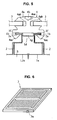
- FIG. 6 is a perspective explanatory view showing an example of a photovoltaic power generation panel used in the photovoltaic power generation outer surrounding structure in accordance with the present invention
- Fig. 7 is a perspective explanatory view showing an example of a zipper gasket used in the photovoltaic power generation outer surrounding structure in accordance with the present invention.
- reference numeral 1 denotes a long fixing member which is provided with a portion 1a fixed onto a base material S such as a roofing board, a base material, an intermediate post or the like of a building and protruding portions 1b arranged in parallel to the portion 1a in both sides in an outdoor side over a longitudinal direction.
- a plurality of long fixing members 1 are fixed onto the base material S at a predetermined interval in a perpendicular direction to a water slope direction in such a manner that a longitudinal direction thereof is in parallel to the water slope direction.
- the long fixing member 1 serves for fixing an outer surrounding body 2 and a zipper gasket 4 which are mentioned below onto the base material S of the building.
- the protruding portions 1b which are in parallel to the portion 1a fixed onto the base material S of the building are provided respectively in both sides in the outdoor side over the longitudinal direction.
- the protruding portions 1b fix the outer surrounding body 2 onto the base material S of the building by pinching and fixing the protruding portions 1b and fixing portions 2a of the outer surrounding body 2 by a pinching and fixing portion 4ac of a gasket main body 4a of the zipper gasket 4 mentioned below in a state in which the fixing portion 2a is arranged along the protruding portions 1b, and support a photovoltaic power generation panel 3 mentioned below pinched by and fixed to the zipper gasket 4.
- the protruding portions 1b exist in the fixing member 1, it is possible to fix the outer surrounding body 2 to the fixing member 1 by the zipper gasket 4 in a state in which a weathering performance is especially improved, and one zipper gasket 4 can be functioned as the fixing member of the outer surrounding body 2 and the photovoltaic power generation panel 3.
- the fixing member 1 is not particularly limited as far as the protruding portions 1b which are in parallel to the portion 1a fixed onto the base material S of the building are provided respectively in both sides in the outdoor side over the longitudinal direction, and a plurality of fixing members are fixed onto the base material S at the predetermined interval in the perpendicular direction to the water slope direction in such a manner that the longitudinal direction becomes in parallel to the water slope direction.
- the fixing member is constituted by a shaped steel 1c formed in a shape that the outdoor side is closed over the longitudinal direction as shown in Fig.
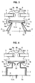
- the fixing member is constituted by a shaped steel 1c having an opening portion 1d in the outdoor side over the longitudinal direction and provided with no protruding portion 1b and a protruding portion forming member 1e having a portion inserted and locked to the opening portion 1d of the shaped steel 1c over the longitudinal direction and a portion forming the protruding portions 1b in both sides as shown in Fig. 4, there exist various aspects such as an aspect that the fixing member is constituted by a shaped steel 1c having the opening portion 1d in the outdoor side over the longitudinal direction, and the like as shown in Figs 1, 2 and 5.
- the shaped steel 1c is formed by a hat shaped steel that each of lips forming the protruding portions 1b is formed so as to be positioned in the outdoor side as shown in Figs. 1 and 2, or the shaped steel 1c is formed such that a width of the opening portion 1d is shorter than a width of the portion 1a fixed onto the base material S of the building as shown in Fig 5.
- a preferable aspect can be approximately selected among the various aspects mentioned above in correspondence to a condition of the field, a material or the like.
- the fixing member 1 is constituted by the shaped steel 1c forming the shape in which the outdoor side is closed over the longitudinal direction as shown in Fig. 3, it is possible to improve a rigidity in the outdoor side of the fixing member 1 and the structure is preferable. Further, in accordance with the aspect that the fixing member 1 is constituted by the shaped steel 1c having the opening portion 1d in the outdoor side over the longitudinal direction and provided with no protruding portion 1b and the protruding portion forming member 1e having the portion inserted and locked to the opening portion 1d of the shaped steel 1c over the longitudinal direction and the portion forming the protruding portions 1b in both sides as shown in Fig.
- the fixing member 1 is constituted by the shaped steel 1c having the opening portion 1d in the outdoor side over the longitudinal direction as shown in Figs 1, 2 and 5, since the portion 1a to be fixed onto the base material S of the building can be fixed onto the base material S of the building by using the fixing device such as the screw, the nail or the like from the opening portion 1d, the installation property is improved, and the structure is preferable.
- the structure is preferable because it is possible to further improve the weathering performance.
- the fixing member 1 is constituted by the shaped steel 1c having the opening portion 1d in the outdoor side over the longitudinal direction
- a cap member 1f having a portion extending along the protruding portions 1b in both sides and a fitting portion 1g fitted to the opening portion 1d of the shaped steel 1c is arranged in the opening portion 1d of the shaped steel 1c of the fixing member 1 as shown in Figs. 1, 2 and 5, the structure is preferable because a rigidity of the fixing member can be improved.
- the cap member 1f having the portion extending along the protruding portions 1b in both sides and having the fitting portion 1g fitted to the opening portion 1d of the shaped steel 1c is arranged in the opening portion 1d of the shaped steel 1c of the fixing member 1, if the cap member 1f is constituted by a cap member pinching the fixing portions 2a of the outer surrounding body 2 along the protruding portions 1b in both side edge portions as shown in Figs. 1 and 2, the structure is preferable because it is possible to further improve the weathering performance.
- the structure is preferable because it is possible to improve the weathering performance.
- Reference numeral 2 denotes the outer surrounding body which is arranged on the base material S between the fixing members 1 and 1, and is provided with the fixing portions 2a risen to the fixing member 1 side and extending along the indoor side surface of the protruding portion 1b of the fixing member 1 in both ends.
- the outer surrounding body 2 is pinched and fixed to the fixing member 1 by the zipper gasket 4 mentioned below so as to cover the outer periphery of the building such as the roof, the outer wall or the like.
- the outer surrounding body 2 can employ anything as far as the fixing portion 2a extending along the indoor side surface of the protruding portion 1b of the fixing member 1 is provided at least in both ends thereof so as to be risen up to the fixing member 1 side.
- the outer surrounding body 2 may be formed in a flat shape between the portion risen up to the fixing member 1 side in both ends as shown in Figs. 1 to 5, or may be formed in a folded plate shape (not shown).
- the fixing portion 2a of the outer surrounding body 2 extends along the outdoor side of the protruding portion 1b of the fixing member 1 as shown in Fig. 3, not only the structure is preferable because it is possible to increase the attaching strength of the outer surrounding body 2, but also the structure is preferable because the weathering performance is improved.
- Reference numeral 3 denotes the photovoltaic power generation panel in which the width is formed shorter than the distance between the centers of the adjacent fixing members 1.
- the photovoltaic power generation panel 3 serves for converting a solar energy into an electric power.
- the photovoltaic power generation panel 3 is constituted by a general structure provided with a solar battery converting the solar energy into the electric power, and is not particularly limited as far as at least the width thereof is formed shorter than the distance between the centers of the adjacent fixing members 1 so as to be pinched and fixed between the fixing members 1 and 1 by the zipper gasket 4 mentioned below pinching and fixing the protruding portion 1b of the fixing member 1 and the fixing portion 2a of the outer surrounding body 2.
- a plurality of photovoltaic power generation panels 3 are held over the longitudinal direction of the outer surrounding body 2, if the photovoltaic power generation panel 3 shown in Fig.
- the general photovoltaic power generation panel 3 is structured such that a wiring cable for inputting and outputting the electric power converted in the solar battery protrudes from a back surface side thereof, and the wiring is executed by connecting the wiring cable protruding from the back surface side or the like to the wiring cable or the like of the adjacent photovoltaic power generation panel 3 at a time of the installation.
- the installation performance is very bad.
- the convex terminal 3a protrudes in the longitudinal direction of the outer surrounding body 2 and the concave terminal 3a engaging with the convex terminal 3a is provided in the opposite side, for example, as shown in Fig. 6, it is possible to easily execute the wiring between the photovoltaic power generation panels 3 and 3 only by fitting the terminal 3a of the photovoltaic power generation panel 3 to be installed to the terminal 3a of the adjacent photovoltaic power generation panel 3 so as to be engaged at a time of the installation. Accordingly, since it is possible to further improve the installation property, the structure is preferable.
- the zipper gasket 4 is constituted by a gasket main body 4a formed by a long elastic material in which a zipper fitting groove 4aa is formed in an approximately center portion in the outdoor side over the longitudinal direction, a panel groove 4ab to which a side edge portion of the photovoltaic power generation panel 3 is inserted is formed in both side portions in the outdoor side over the longitudinal direction and a pinching and fixing portion 4ac pinching and fixing the protruding portions 1b of the fixing members 1 and the fixing portions 2a of the outer surrounding body 2 is formed in both side portions in the indoor side over the longitudinal direction respectively, and a long zipper body 4b which is fitted into the zipper fitting groove 4aa of the gasket main body 4a, and pinching and fixing each of side edge portions of the photovoltaic power generation panel 3 inserted to the panel groove 4ab in the outdoor side of the fixing members 1 by fitting the zipper body 4b into the zipper fitting groove 4aa of the gasket main body 4a in a state in which the zipper body 4b into the zipper fitting groove 4a
- the zipper gasket 4 serves for pinching and fixing the outer surrounding body 2 to the fixing members 1 in a state in which the weathering performance is good, that is, no hole through the fixing members 1 or the outer surrounding body 2 exists in the outdoor side thereof, the screw, the nail or the like is not exposed and the end portion of the outer surrounding body 2 is tightly attached to the fixing members 1, pinching and fixing the photovoltaic power generation panel 3 between the fixing members 1 and 1, and insulating between the fixing member 1 and the outer surrounding body 2, and the photovoltaic power generation panel 3, thereby preventing the corrosion from being generated due to the potential difference between the different metals.
- the zipper fitting groove 4aa is formed in the approximately center portion in the outdoor side over the longitudinal direction, and the panel groove 4ab to which the side edge portion of the photovoltaic power generation panel 3 is inserted is formed in both side portions in the outdoor side over the longitudinal direction as shown in Fig. 7.
- the portions in the outdoor side positioned in both sides of the zipper fitting groove 4aa of the gasket main body 4a can be deformed in a direction narrowing the width of the zipper fitting groove 4aa.
- the zipper body 4b is fitted into the zipper fitting groove 4aa of the gasket main body 4a by using a special tool or the like in a state in which the side edge portions of the photovoltaic power generation panel 3 is inserted to the respective panel grooves 4ab and 4ab of the gasket main body 4a as mentioned above, a strong pressing force is applied to the zipper fitting groove 4aa in the direction narrowing the widths of the respective panel grooves 4ab and 4ab of the gasket main body 4a via the portions in both sides of the zipper fitting groove 4aa while being expanded in the width. Accordingly, the side edge portions of the photovoltaic power generation panel 3 inserted to the respective panel grooves 4ab and 4ab of the gasket main body 4a are strongly pinched.
- the zipper gasket 4 is structured as to strongly pinch each of the side edge portions of the photovoltaic power generation panels 3 inserted to the panel grooves 4ab and 4ab of the gasket main body 4a by simply fitting the zipper body 4b into the zipper fitting groove 4aa of the gasket main body 4a without using the adhesive agent, the fixing screw or the like.
- the pinching and fixing portion 4ac pinching and fixing the protruding portion 1b of the fixing member 1 and the fixing portion 2a of the outer surrounding body 2 in both side portions in the indoor side over the longitudinal direction thereof as shown in Fig. 7 is formed in the gasket main body 4a of the zipper gasket 4, and the pinching and fixing portion 4ac is structured, as shown in Figs. 1 to 5, such as to pinch and fix the protruding portion 1b of the fixing member 1 and the fixing portion 2a of the outer surrounding body 2, and seal the portion between the fixing member 1 and the outer surrounding body 2 in such a manner as to prevent the rain water or the like from entering into the indoor side of the fixing member 1 and the indoor side of the outer surrounding body 2.
- any shape can be employed as far as the pinching and fixing portion pinches and fixes the protruding portions 1b of the fixing members 1 and the fixing portions 2a of the outer surrounding body 2 in both side portions in the indoor side over the longitudinal direction.
- the pinching and fixing portion 4ac as shown in Figs. 1 to 5 and 7 is formed in such a shape that the grooves formed in the concave shape toward the center line side of the gasket main body 4a so as to enwrap the protruding portions 1b of the fixing members 1 and the fixing portions 2a of the outer surrounding body 2 along the protruding portions 1b are formed in both side edge sides.
- the protruding portion 1b of one fixing member 1 and the fixing portion 2a of the outer surrounding body 2 are pinched to one groove of the pinching and fixing portions 4ac in a state in which the fixing portion 2a of the outer surrounding body 2 is arranged along the indoor surface side of the protruding portion 1b of the fixing member 1, and the protruding portion 1b of the other fixing member 1 in a state in which the fixing portion 2a of the outer surrounding body 2 is arranged along the indoor surface side of the protruding portion 1b of the fixing member 1 is thereafter pinched by deforming the other groove of the pinching and fixing portion 4ac by a paddle, the special tool or the like in such a manner as to expand the width thereof, that is, move the lower end side of the pinching and fixing portion 4ac apart from the center line of the gasket main body 4a.
- the zipper gasket 4 is structured such as to firmly pinch and fix the photovoltaic power generation panel 3 by the gasket main body 4a and the zipper body 4b, and pinch and fix the fixing portions 2a of the outer surrounding body 2 to the protruding portions 1b of the fixing members 1 in such a manner as to prevent the rain water from entering into the indoor side of the fixing members 1 and the indoor side of the outer surrounding body 2 by the pinching and fixing portion 4ac of the gasket main body 4a, it is possible to insulate between the fixing member 1 and the outer surrounding body 2, and the photovoltaic power generation panel 3 so as to prevent the corrosion due to the potential difference between the different metals from being generated, and it is possible to easily install.
- the material of the zipper gasket 4 is not particularly limited as far as at least the gasket main body 4a is constituted by the long elastic material, however, as the material of the gasket main body 4a and the zipper body 4b, it is preferable to employ a thermoplastic elastomer such as a styrene, olefin or the like, a synthetic rubber such as a diene, organic silicon compound or the like, a natural rubber and the like.
- the operation is executed so as to fix a plurality of fixing members 1 onto the base material S at the predetermined interval in the perpendicular direction to the water slope direction in such a manner that the longitudinal direction become in parallel to the water slope direction in accordance with the generally employed method.
- the fixing member 1 is constituted by the shaped steel 1c formed in the shape in which the outdoor side is closed over the longitudinal direction, as shown in Fig. 3, it is sufficient that the portion 1a fixed onto the base material S of the building is fixed onto the base material S by the nail, the screw or the like.
- the fixing member 1 is constituted by the shaped steel 1c having the opening portion 1d in the outdoor side over the longitudinal direction and provided with no protruding portion 1b and the protruding portion forming member 1e having the portion inserted and locked to the opening portion 1d of the shaped steel 1c over the longitudinal direction and the portion forming the protruding portions 1b in both sides
- the portion 1a fixed onto the base material S of the building is first fixed onto the base material S of the building by the fixing device such as the nail, the screw or the like from the opening portion 1d of the shaped steel 1c, and the portion in which the shaped steel 1c of the protruding portion forming member 1e is inserted and locked to the opening portion 1d of the shaped steel 1c (the tapered portion formed in the lower side of the protruding portion forming member 1e in Fig. 4) is thereafter inserted.
- the fixing member 1 is constituted by the shaped steel 1c having the opening portion 1d in the outdoor side over the longitudinal direction, it is sufficient that the portion 1a fixed onto the base material S of the building is fixed by the fixing device such as the nail, the screw or the like from the opening portion 1d of the shaped steel 1c.
- the fixing member 1 is constituted by the shaped steel 1c having the opening portion 1d in the outdoor side over the longitudinal direction
- the cap member 1f having the portions extending along the protruding portions 1b in both sides and having the fitting portion 1g fitted to the opening portion 1d of the shaped steel 1c is arranged in the opening portion 1d of the shaped steel 1c of the fixing member 1 as shown in Fig. 5, it is sufficient that the fitting portion 1g of the cap member 1f is fitted to the opening portion 1d of the shaped steel 1c after fixing the shaped steel 1c onto the base material S of the building.
- the operation is executed by arranging the outer surrounding body 2 on the base material S between the fixing members 1 and 1 such that the respective fixing portions 2a of the outer surrounding body 2 are arranged along the protruding portions 1b of the respective fixing members 1 as shown in Figs. 1 to 6.
- the fixing member 2a of the outer surrounding body 2 is formed in the shape extending along the outdoor side of the protruding portion 1b of the fixing member 1, it is sufficient that the fixing portion 2a of the outer surrounding body 2 is bent from the indoor side of the protruding portion 1b of the fixing member 1 to the outdoor side along them so as to arrange the outer surrounding body 2 on the base material S between the fixing members 1 and 1.
- the fixing portions 2a of the outer surrounding body 2 extending along the protruding portions 1b in both side edge portions may be pinched by arranging the outer surrounding body 2 on the base material S between the fixing members 1 and 1 in such a manner that the respective fixing portions 2a of the outer surrounding body 2 are arranged along the protruding portions 1b of the respective fixing members 1, then mounting the cap member 1f in the outdoor side of the fixing members 1, and thereafter caulking or lock seaming both side edge portions of the cap member 1f.
- the fixing member 1 is constituted by the shaped steel 1c having the opening portion 1d in the outdoor side over the longitudinal direction
- the cap member 1f having the portion extending along the protruding portions 1b in both sides and having the fitting portion 1g fitted to the opening portion 1d of the shaped steel 1c is arranged in the opening portion 1d of the shaped steel 1c of the fixing member 1
- the cap member 1f is constituted by a cap member pinching the fixing portions 2a of the outer surrounding body 2 extending along the protruding portion 1b in both side edge portions as shown in Fig.
- the protruding portions 1b of the fixing members 1 and the fixing portions 2a of the outer surrounding body 2 may be pinched in both side edge portions by arranging the outer surrounding body 2 on the base material S between the fixing members 1 and 1 in such a manner that the respective fixing portions 2a of the outer surrounding body 2 are arranged along the protruding portions 1b of the respective fixing members 1, then fitting the fitting portion 1g of the cap member 1f to the opening portion 1d of the shaped steel 1c, and thereafter caulking or lock seaming both side edge portions of the cap member 1f.
- the operation is executed by pinching the protruding portions 1b of one fixing member 1 and the fixing portions 2a of the outer surrounding body 2 to one groove of the pinching and fixing portions 4ac in a state in which the fixing portions 2a of the outer surrounding body 2 are arranged along the indoor surface side of the protruding portions 1b of the fixing members 1, and thereafter deforming the other groove of the pinching and fixing portions 4ac by the paddle, the special tool or the like in such a manner as to expand the width thereof, that is, move the lower end side of the pinching and fixing portion 4ac apart from the center line of the gasket main body 4a, thereby pinching the protruding portions 1b of the other fixing member 1 in a state in which the fixing portions 2a of the outer surrounding body 2 are arranged along the indoor surface side of the protruding portions 1b of the fixing members 1.
- This operation may be executed by using the special tool or the like. However, since the groove 4ab for the installation portion or the panel groove 4ab in the gasket main body 4a is in a state in which nothing is inserted thereto, it is possible to easily take out the zipper body 4b generally by hand. Further, this operation may be previously executed in a preliminary step, however, it is necessary to execute the operation at least before executing an operation of inserting the side edge portions of the respective photovoltaic power generation panels 3 and 3 to the respective panel grooves 4ab which is mentioned below.
- the portions in both sides of the zipper fitting groove 4aa of the gasket main body 4a can respectively broaden the widths of the panel grooves 4ab of the gasket main body 4a by deforming the width of the zipper fitting groove 4aa in the narrowing direction. Accordingly, it is possible to easily insert the side edge portion of the photovoltaic power generation panel 3.
- the photovoltaic power generation panel 3 is not pinched and fixed to the zipper gasket 4, for example, due to a budget or a peripheral sunlight irradiation condition, it is preferable to insert a decorative laminated sheet in place of the photovoltaic power generation panel 3 to the panel grooves 4ab of the gasket main body 4a.
- the decorative laminated sheet employs a decorative laminated sheet in which a surface in the outdoor side of the decorative laminated sheet is made flush with the outdoor side surface of the photovoltaic power generation panel 3 (which is pinched and fixed to a right side of the zipper gasket 4 in a right side in Fig. 1) at a time of the installation, as shown in Fig. 1, a design property after the installation is improved, and the structure is preferable.
- This operation is particularly executed by fitting the zipper body 4b into the zipper fitting groove 4aa of the gasket main body 4a by using the special tool or the like, in a state in which the side edge portions of the respective photovoltaic power generation panels 3 and 3 are inserted to the respective penal grooves 4ab and 4ab of the gasket main body 4a.
- the zipper body 4b is fitted into the zipper fitting groove 4aa of the gasket main body 4a in a state in which the side edge portions of the photovoltaic power generation panels 3 and 3 are respectively inserted to the respective panel grooves 4ab and 4ab of the gasket main body 4a
- the strong pressing force is applied in the direction of narrowing the width of the respective panel grooves 4ab and 4ab of the gasket main body 4a via the portions in both sides of the zipper fitting groove 4aa in accordance that the width of the zipper fitting groove 4aa is expanded. Accordingly, the side edge portions of the respective photovoltaic power generation panels 3 and 3 inserted to the respective panel grooves 4ab and 4ab are respectively strongly pinched and fixed.
- the wiring or the like between the photovoltaic power generation panels 3 and 3 may be executed by utilizing the space formed between the indoor side of the photovoltaic power generation panel 3 and the outdoor side of the outer surrounding body 2, after installing the photovoltaic power generation outer surrounding structure in accordance with the present invention.
Applications Claiming Priority (1)
| Application Number | Priority Date | Filing Date | Title |
|---|---|---|---|
| JP2005301762A JP2007107345A (ja) | 2005-10-17 | 2005-10-17 | 太陽光発電外囲構造 |
Publications (2)
| Publication Number | Publication Date |
|---|---|
| EP1775777A2 true EP1775777A2 (fr) | 2007-04-18 |
| EP1775777A3 EP1775777A3 (fr) | 2010-11-03 |
Family
ID=37708275
Family Applications (1)
| Application Number | Title | Priority Date | Filing Date |
|---|---|---|---|
| EP06020430A Withdrawn EP1775777A3 (fr) | 2005-10-17 | 2006-09-28 | Structure extérieure d'un système photovoltaïque de production d'energie |
Country Status (7)
| Country | Link |
|---|---|
| US (1) | US20070084504A1 (fr) |
| EP (1) | EP1775777A3 (fr) |
| JP (1) | JP2007107345A (fr) |
| KR (1) | KR20070042070A (fr) |
| CN (1) | CN1952320B (fr) |
| CA (1) | CA2562464A1 (fr) |
| TW (1) | TW200716835A (fr) |
Cited By (13)
| Publication number | Priority date | Publication date | Assignee | Title |
|---|---|---|---|---|
| DE102008009608A1 (de) * | 2008-02-18 | 2009-10-15 | Niemetz Metall Gmbh | Einrichtung mit einem Flächenelement und einer Klemmeinrichtung |
| WO2010089469A1 (fr) * | 2009-02-06 | 2010-08-12 | Sun'r | Pièce de montage pour modules photovoltaïques, dispositif de montage et structure de bâtiment l'incorporant |
| ITBO20090271A1 (it) * | 2009-05-05 | 2010-11-06 | Elettropiemme S R L | Telaio di supporto per pannelli solari |
| WO2011007201A1 (fr) | 2009-07-16 | 2011-01-20 | Iscom S.P.A. | Section de montage pour panneau solaire |
| FR2951757A1 (fr) * | 2009-10-27 | 2011-04-29 | B A C Acier | Dispositif de maintien d'un panneau solaire sur une couverture d'un batiment |
| EP2369264A3 (fr) * | 2010-03-15 | 2012-01-25 | Fakro PP Spolka Z O.O. | Couverture de protection |
| EP2413381A2 (fr) * | 2010-07-29 | 2012-02-01 | First Solar, Inc. | Procédé et appareil pour la fourniture d'une installation simplifiée d'une pluralité de panneaux solaires |
| WO2012016036A3 (fr) * | 2010-07-29 | 2012-04-05 | First Solar, Inc | Appareil facilitant le montage de panneaux solaires sur un ensemble à rail |
| FR2969743A1 (fr) * | 2010-12-23 | 2012-06-29 | Kogys | Element d'assemblage compensateur de dilatation pour ossature metallique support de panneaux solaires |
| EP2573486A3 (fr) * | 2011-09-20 | 2013-06-26 | REHAU AG + Co | Élément de serrage pour un système de fixation pour éléments en forme de plaque, système de fixation comprenant un tel élément de serrage et son utilisation |
| WO2012075149A3 (fr) * | 2010-12-01 | 2013-06-27 | First Solar, Inc. | Procédé et appareil permettant l'installation simplifiée d'une pluralité de panneaux solaires |
| WO2013092905A1 (fr) * | 2011-12-21 | 2013-06-27 | Vincent Industrie | Element et methode de fixation d'au moins un panneau photovoltaïque sur un rail et installation et ensemble comprenant au moins un tel element |
| EP3240188A4 (fr) * | 2014-12-26 | 2018-07-25 | Kyocera Corporation | Module de cellules solaires et réseau de cellules solaires l'utilisant |
Families Citing this family (30)
| Publication number | Priority date | Publication date | Assignee | Title |
|---|---|---|---|---|
| JP4108724B1 (ja) * | 2007-02-23 | 2008-06-25 | シャープ株式会社 | 構造物設置架台 |
| EP2099077A1 (fr) * | 2008-03-06 | 2009-09-09 | Inventux Technologies AG | Module pour convertir un rayonnement solaire en électricité |
| JP5153406B2 (ja) * | 2008-03-28 | 2013-02-27 | 三菱電機株式会社 | 太陽電池モジュールの取り付け装置 |
| DE102008027857A1 (de) * | 2008-06-11 | 2009-03-05 | Leichtmetallbau Schletter Gmbh | Montagesystem für PV-Module |
| JP5205249B2 (ja) * | 2008-12-12 | 2013-06-05 | Jx日鉱日石エネルギー株式会社 | 太陽電池モジュールの取付構造及び取付方法 |
| JP5205250B2 (ja) * | 2008-12-12 | 2013-06-05 | Jx日鉱日石エネルギー株式会社 | 太陽電池モジュールの取付構造及び取付方法 |
| DE202009007526U1 (de) * | 2009-05-27 | 2009-08-20 | Schletter Gmbh | Vorrichtung zur Befestigung einer Montageschiene an einem Gewindeschaft |
| DE102009054242A1 (de) * | 2009-11-21 | 2011-05-26 | Juwi R & D Research Development Gmbh & Co. Kg | Vorrichtung zur Befestigung mindestens eines Solarmoduls |
| DE102010021713A1 (de) * | 2010-05-27 | 2011-12-01 | Schletter Gmbh | Befestigung einer Tragschiene für ein PV-Modul auf einem Trapezblech |
| DE102010023212A1 (de) * | 2010-06-09 | 2011-12-15 | Schletter Gmbh | Tragprofil einer Reihe von PV-Modulen |
| US8418983B2 (en) | 2010-07-29 | 2013-04-16 | First Solar, Inc. | Slider clip and photovoltaic structure mounting system |
| AT511006B1 (de) * | 2010-11-19 | 2012-11-15 | Nocker Thomas | Montagesystem und verfahren zur befestigung von solarmodulrahmen auf darunterliegende primärschienen |
| KR20120096175A (ko) | 2011-02-22 | 2012-08-30 | 엘지전자 주식회사 | 태양전지 모듈용 프레임 시스템 |
| FR2974163B1 (fr) * | 2011-04-15 | 2018-06-22 | Ciel Et Terre International | Dispositif support de panneau |
| US9160273B2 (en) * | 2011-07-08 | 2015-10-13 | Unirac, Inc. | Universal end clamp |
| CN102339870B (zh) * | 2011-09-14 | 2013-03-20 | 东莞市中海光电材料有限公司 | 弹性夹具及具有该弹性夹具的太阳能电池板安装组件 |
| CN103208541B (zh) * | 2012-01-12 | 2015-09-09 | 中电电气(上海)太阳能科技有限公司 | 一种快速安装太阳能光伏组件及支架的系统 |
| JP5963463B2 (ja) * | 2012-02-02 | 2016-08-03 | シャープ株式会社 | 太陽電池モジュールの設置構造、太陽電池モジュールの設置方法、太陽電池モジュール設置用桟、及び太陽光発電システム |
| US8640402B1 (en) * | 2012-03-08 | 2014-02-04 | Henry H. Bilge | Building roof fascia, coping and/or solar panel connector arrangement |
| US20130240008A1 (en) * | 2012-03-16 | 2013-09-19 | Christopher Baker | System and method for mounting photovoltaic modules |
| DE102012209272A1 (de) * | 2012-06-01 | 2013-12-05 | Hilti Aktiengesellschaft | Befestigungsvorrichtung für Solarpaneele |
| US20140069878A1 (en) * | 2012-09-10 | 2014-03-13 | Primestar Solar, Inc. | Racking system for supporting photovoltaic module mounting and methods of its use |
| JP6118099B2 (ja) * | 2012-12-17 | 2017-04-19 | 株式会社タケチ | パネルの固定装置および設置方法 |
| JP6358693B2 (ja) * | 2014-02-16 | 2018-07-18 | 株式会社 丸光 | 太陽光パネル取付金具 |
| CN105262416B (zh) * | 2015-09-25 | 2017-09-01 | 湖南红太阳新能源科技有限公司 | 用于梯形瓦屋面安装的固定装置 |
| CN207392624U (zh) * | 2017-09-30 | 2018-05-22 | 杭州桑尼能源科技股份有限公司 | 用于建筑一体化屋顶发电系统的横向水槽 |
| US11402058B2 (en) | 2019-05-14 | 2022-08-02 | Field Energy Ops, Inc. | Boltless module support structures and boltless module attachment method |
| KR102081387B1 (ko) * | 2019-08-28 | 2020-05-29 | (주)세화에너지산업 | 태양광모듈 설치용 고정장치 |
| CN111928497B (zh) * | 2020-08-04 | 2021-10-15 | 江苏紫泉综合能源服务有限公司 | 一种光伏太阳能系统 |
| JP7360227B1 (ja) | 2023-02-14 | 2023-10-12 | 株式会社 Fd | ソーラパネルの取付金具 |
Citations (7)
| Publication number | Priority date | Publication date | Assignee | Title |
|---|---|---|---|---|
| GB1011881A (en) * | 1960-12-09 | 1965-12-01 | Williams & Williams Ltd | Structural assemblies for windows, walls and the like |
| DE19502215A1 (de) * | 1995-01-25 | 1996-08-01 | Zsw | Dachintegriertes Photovoltaik-Modulsystem |
| JPH10231600A (ja) * | 1997-02-18 | 1998-09-02 | Daiwa House Ind Co Ltd | 建築物への太陽電池取付構造 |
| JPH10292740A (ja) * | 1997-04-14 | 1998-11-04 | Takechi Kogyo Rubber Kk | 建築用ジッパーガスケットの取付構造 |
| JP2000230300A (ja) * | 1999-02-12 | 2000-08-22 | Tsutsunaka Plast Ind Co Ltd | 窓材用ジッパーガスケット |
| US20030094193A1 (en) * | 2001-11-16 | 2003-05-22 | First Solar, Llc | Photovoltaic array |
| DE20318118U1 (de) * | 2003-11-21 | 2004-03-11 | Leber, Hermann | Photovoltaikdach |
Family Cites Families (10)
| Publication number | Priority date | Publication date | Assignee | Title |
|---|---|---|---|---|
| US3744113A (en) * | 1971-03-22 | 1973-07-10 | Standard Products Co | Lock strip inserting tool |
| US4835927A (en) * | 1987-02-19 | 1989-06-06 | The Standard Products Company | Prefabricated glazing gasket |
| JP3321630B2 (ja) * | 1994-01-26 | 2002-09-03 | 株式会社藤田兼三工業 | 屋 根 |
| JP3007073B2 (ja) * | 1998-05-29 | 2000-02-07 | 株式会社淀川製鋼所 | 屋根板における太陽電池モジュールの設置構造 |
| JP2000204854A (ja) * | 1999-01-11 | 2000-07-25 | Fuso Rubber Kogyo Kk | ジッパ―ガスケット |
| JP2001254494A (ja) * | 2000-03-10 | 2001-09-21 | Kanegafuchi Chem Ind Co Ltd | 太陽電池モジュール、太陽電池ユニット及び太陽電池パネルの設置方法 |
| JP2002332720A (ja) * | 2001-05-09 | 2002-11-22 | Nkk Steel Sheet & Strip Corp | 箱型はぜ葺き屋根、太陽電池モジュール板を組み込んだ箱型はぜ葺き屋根、太陽電池モジュール板の取りつけ、取り外し方法および屋根の施工方法 |
| DE10237926A1 (de) * | 2002-08-14 | 2004-02-26 | Stefan Nau Gmbh | Im Aussenbereich angebrachter Gegenstand |
| JP4110403B2 (ja) * | 2003-06-24 | 2008-07-02 | 国際技術開発株式会社 | 真空平板式太陽熱収集装置 |
| ITTO20031035A1 (it) * | 2003-12-23 | 2005-06-24 | Isolpack S P A | Pannello isolante per edilizia. |
-
2005
- 2005-10-17 JP JP2005301762A patent/JP2007107345A/ja active Pending
-
2006
- 2006-05-22 TW TW095118080A patent/TW200716835A/zh unknown
- 2006-08-18 US US11/505,940 patent/US20070084504A1/en not_active Abandoned
- 2006-09-22 KR KR1020060092027A patent/KR20070042070A/ko not_active Application Discontinuation
- 2006-09-28 EP EP06020430A patent/EP1775777A3/fr not_active Withdrawn
- 2006-10-04 CA CA002562464A patent/CA2562464A1/fr not_active Abandoned
- 2006-10-17 CN CN2006101356042A patent/CN1952320B/zh not_active Expired - Fee Related
Patent Citations (7)
| Publication number | Priority date | Publication date | Assignee | Title |
|---|---|---|---|---|
| GB1011881A (en) * | 1960-12-09 | 1965-12-01 | Williams & Williams Ltd | Structural assemblies for windows, walls and the like |
| DE19502215A1 (de) * | 1995-01-25 | 1996-08-01 | Zsw | Dachintegriertes Photovoltaik-Modulsystem |
| JPH10231600A (ja) * | 1997-02-18 | 1998-09-02 | Daiwa House Ind Co Ltd | 建築物への太陽電池取付構造 |
| JPH10292740A (ja) * | 1997-04-14 | 1998-11-04 | Takechi Kogyo Rubber Kk | 建築用ジッパーガスケットの取付構造 |
| JP2000230300A (ja) * | 1999-02-12 | 2000-08-22 | Tsutsunaka Plast Ind Co Ltd | 窓材用ジッパーガスケット |
| US20030094193A1 (en) * | 2001-11-16 | 2003-05-22 | First Solar, Llc | Photovoltaic array |
| DE20318118U1 (de) * | 2003-11-21 | 2004-03-11 | Leber, Hermann | Photovoltaikdach |
Cited By (16)
| Publication number | Priority date | Publication date | Assignee | Title |
|---|---|---|---|---|
| DE102008009608A1 (de) * | 2008-02-18 | 2009-10-15 | Niemetz Metall Gmbh | Einrichtung mit einem Flächenelement und einer Klemmeinrichtung |
| WO2010089469A1 (fr) * | 2009-02-06 | 2010-08-12 | Sun'r | Pièce de montage pour modules photovoltaïques, dispositif de montage et structure de bâtiment l'incorporant |
| ITBO20090271A1 (it) * | 2009-05-05 | 2010-11-06 | Elettropiemme S R L | Telaio di supporto per pannelli solari |
| WO2011007201A1 (fr) | 2009-07-16 | 2011-01-20 | Iscom S.P.A. | Section de montage pour panneau solaire |
| FR2951757A1 (fr) * | 2009-10-27 | 2011-04-29 | B A C Acier | Dispositif de maintien d'un panneau solaire sur une couverture d'un batiment |
| EP2369264B1 (fr) | 2010-03-15 | 2013-06-05 | Fakro PP Spolka Z O.O. | Couverture de protection |
| EP2369264A3 (fr) * | 2010-03-15 | 2012-01-25 | Fakro PP Spolka Z O.O. | Couverture de protection |
| EP2413381A2 (fr) * | 2010-07-29 | 2012-02-01 | First Solar, Inc. | Procédé et appareil pour la fourniture d'une installation simplifiée d'une pluralité de panneaux solaires |
| WO2012016036A3 (fr) * | 2010-07-29 | 2012-04-05 | First Solar, Inc | Appareil facilitant le montage de panneaux solaires sur un ensemble à rail |
| EP2413381A3 (fr) * | 2010-07-29 | 2013-05-01 | First Solar, Inc. | Procédé et appareil pour la fourniture d'une installation simplifiée d'une pluralité de panneaux solaires |
| WO2012075149A3 (fr) * | 2010-12-01 | 2013-06-27 | First Solar, Inc. | Procédé et appareil permettant l'installation simplifiée d'une pluralité de panneaux solaires |
| FR2969743A1 (fr) * | 2010-12-23 | 2012-06-29 | Kogys | Element d'assemblage compensateur de dilatation pour ossature metallique support de panneaux solaires |
| EP2573486A3 (fr) * | 2011-09-20 | 2013-06-26 | REHAU AG + Co | Élément de serrage pour un système de fixation pour éléments en forme de plaque, système de fixation comprenant un tel élément de serrage et son utilisation |
| WO2013092905A1 (fr) * | 2011-12-21 | 2013-06-27 | Vincent Industrie | Element et methode de fixation d'au moins un panneau photovoltaïque sur un rail et installation et ensemble comprenant au moins un tel element |
| FR2985001A1 (fr) * | 2011-12-21 | 2013-06-28 | Vincent Ind | Element et methode de fixation d'au moins un panneau photovoltaique sur un rail et installation et ensemble comprenant au moins un tel element |
| EP3240188A4 (fr) * | 2014-12-26 | 2018-07-25 | Kyocera Corporation | Module de cellules solaires et réseau de cellules solaires l'utilisant |
Also Published As
| Publication number | Publication date |
|---|---|
| JP2007107345A (ja) | 2007-04-26 |
| US20070084504A1 (en) | 2007-04-19 |
| TW200716835A (en) | 2007-05-01 |
| EP1775777A3 (fr) | 2010-11-03 |
| CA2562464A1 (fr) | 2007-04-17 |
| KR20070042070A (ko) | 2007-04-20 |
| CN1952320A (zh) | 2007-04-25 |
| CN1952320B (zh) | 2010-06-23 |
Similar Documents
| Publication | Publication Date | Title |
|---|---|---|
| EP1775777A2 (fr) | Structure extérieure d'un système photovoltaïque de production d'energie | |
| EP1184526B1 (fr) | Tuile de toit pour module de pile solaire | |
| JP4290750B2 (ja) | 太陽電池モジュールの固定構造、太陽電池モジュール用のフレーム及び固定部材 | |
| EP1860704A2 (fr) | Tuile de toiture solaire | |
| JP2018511721A (ja) | 傾斜屋根用太陽光パネル装着システム | |
| KR101616102B1 (ko) | 태양광 발전모듈 설치방법 | |
| EP1300523A4 (fr) | Module de batterie solaire, structure d'installation pour module de batterie solaire, toit a fonction de production d'energie de la structure d'installation et procede d'installation d'un module de batterie solaire | |
| CA2893726C (fr) | Systeme de toit modulaire pour panneaux solaires | |
| JP4829259B2 (ja) | 太陽電池モジュール固定装置の形成方法 | |
| JP2004300865A (ja) | 太陽電池付き建築用板 | |
| WO2015016244A1 (fr) | Dispositif de cellule solaire | |
| RU2680375C1 (ru) | Устройство электрического соединения фотогальванической установки | |
| JP5403510B2 (ja) | 外設構築物の設置構造 | |
| JP4127610B2 (ja) | 太陽電池モジュール | |
| JP2006307567A (ja) | 太陽光発電外囲構造 | |
| JP6511269B2 (ja) | 屋根構造 | |
| JP4448190B2 (ja) | 太陽電池モジュールの固定部材 | |
| JP2017040065A (ja) | 太陽光発電パネル取付金具 | |
| KR20100006921A (ko) | 박막형 솔라셀 고정 패널 | |
| CN219181486U (zh) | 一种隐蔽线缆式光伏发电幕墙装置 | |
| JP6594626B2 (ja) | 屋根構造 | |
| CN215978107U (zh) | 光伏建筑构件 | |
| CN114396140A (zh) | 一种新型bipv光伏屋面组合板及安装方法 | |
| JP2005282124A (ja) | パネルの取付構造 | |
| WO2015101529A1 (fr) | Agencement de montage pour structure de toiture |
Legal Events
| Date | Code | Title | Description |
|---|---|---|---|
| PUAI | Public reference made under article 153(3) epc to a published international application that has entered the european phase |
Free format text: ORIGINAL CODE: 0009012 |
|
| AK | Designated contracting states |
Kind code of ref document: A2 Designated state(s): AT BE BG CH CY CZ DE DK EE ES FI FR GB GR HU IE IS IT LI LT LU LV MC NL PL PT RO SE SI SK TR |
|
| AX | Request for extension of the european patent |
Extension state: AL BA HR MK YU |
|
| PUAL | Search report despatched |
Free format text: ORIGINAL CODE: 0009013 |
|
| AK | Designated contracting states |
Kind code of ref document: A3 Designated state(s): AT BE BG CH CY CZ DE DK EE ES FI FR GB GR HU IE IS IT LI LT LU LV MC NL PL PT RO SE SI SK TR |
|
| AX | Request for extension of the european patent |
Extension state: AL BA HR MK RS |
|
| RIC1 | Information provided on ipc code assigned before grant |
Ipc: E04F 13/08 20060101ALI20100924BHEP Ipc: E04D 3/38 20060101ALI20100924BHEP Ipc: E04D 3/08 20060101ALI20100924BHEP Ipc: E04D 13/18 20060101ALI20100924BHEP Ipc: H01L 31/048 20060101ALI20100924BHEP Ipc: H01L 31/042 20060101AFI20070213BHEP |
|
| REG | Reference to a national code |
Ref country code: DE Ref legal event code: R108 |
|
| AKY | No designation fees paid | ||
| REG | Reference to a national code |
Ref country code: DE Ref legal event code: R108 Effective date: 20110701 |
|
| STAA | Information on the status of an ep patent application or granted ep patent |
Free format text: STATUS: THE APPLICATION IS DEEMED TO BE WITHDRAWN |
|
| 18D | Application deemed to be withdrawn |
Effective date: 20110504 |