EP1773576B1 - Verfahren und vorrichtung zur herstellung und befüllung von säcken - Google Patents
Verfahren und vorrichtung zur herstellung und befüllung von säcken Download PDFInfo
- Publication number
- EP1773576B1 EP1773576B1 EP05762405A EP05762405A EP1773576B1 EP 1773576 B1 EP1773576 B1 EP 1773576B1 EP 05762405 A EP05762405 A EP 05762405A EP 05762405 A EP05762405 A EP 05762405A EP 1773576 B1 EP1773576 B1 EP 1773576B1
- Authority
- EP
- European Patent Office
- Prior art keywords
- sacks
- sack
- tubular material
- longitudinal seams
- longitudinal
- Prior art date
- Legal status (The legal status is an assumption and is not a legal conclusion. Google has not performed a legal analysis and makes no representation as to the accuracy of the status listed.)
- Not-in-force
Links
Images

Classifications
-
- B—PERFORMING OPERATIONS; TRANSPORTING
- B65—CONVEYING; PACKING; STORING; HANDLING THIN OR FILAMENTARY MATERIAL
- B65B—MACHINES, APPARATUS OR DEVICES FOR, OR METHODS OF, PACKAGING ARTICLES OR MATERIALS; UNPACKING
- B65B1/00—Packaging fluent solid material, e.g. powders, granular or loose fibrous material, loose masses of small articles, in individual containers or receptacles, e.g. bags, sacks, boxes, cartons, cans, or jars
- B65B1/02—Machines characterised by the incorporation of means for making the containers or receptacles
-
- B—PERFORMING OPERATIONS; TRANSPORTING
- B65—CONVEYING; PACKING; STORING; HANDLING THIN OR FILAMENTARY MATERIAL
- B65B—MACHINES, APPARATUS OR DEVICES FOR, OR METHODS OF, PACKAGING ARTICLES OR MATERIALS; UNPACKING
- B65B43/00—Forming, feeding, opening or setting-up containers or receptacles in association with packaging
- B65B43/04—Forming flat bags from webs
-
- B—PERFORMING OPERATIONS; TRANSPORTING
- B65—CONVEYING; PACKING; STORING; HANDLING THIN OR FILAMENTARY MATERIAL
- B65B—MACHINES, APPARATUS OR DEVICES FOR, OR METHODS OF, PACKAGING ARTICLES OR MATERIALS; UNPACKING
- B65B43/00—Forming, feeding, opening or setting-up containers or receptacles in association with packaging
- B65B43/42—Feeding or positioning bags, boxes, or cartons in the distended, opened, or set-up state; Feeding preformed rigid containers, e.g. tins, capsules, glass tubes, glasses, to the packaging position; Locating containers or receptacles at the filling position; Supporting containers or receptacles during the filling operation
- B65B43/46—Feeding or positioning bags, boxes, or cartons in the distended, opened, or set-up state; Feeding preformed rigid containers, e.g. tins, capsules, glass tubes, glasses, to the packaging position; Locating containers or receptacles at the filling position; Supporting containers or receptacles during the filling operation using grippers
- B65B43/465—Feeding or positioning bags, boxes, or cartons in the distended, opened, or set-up state; Feeding preformed rigid containers, e.g. tins, capsules, glass tubes, glasses, to the packaging position; Locating containers or receptacles at the filling position; Supporting containers or receptacles during the filling operation using grippers for bags
-
- B—PERFORMING OPERATIONS; TRANSPORTING
- B65—CONVEYING; PACKING; STORING; HANDLING THIN OR FILAMENTARY MATERIAL
- B65B—MACHINES, APPARATUS OR DEVICES FOR, OR METHODS OF, PACKAGING ARTICLES OR MATERIALS; UNPACKING
- B65B51/00—Devices for, or methods of, sealing or securing package folds or closures; Devices for gathering or twisting wrappers, or necks of bags
- B65B51/10—Applying or generating heat or pressure or combinations thereof
- B65B51/26—Devices specially adapted for producing transverse or longitudinal seams in webs or tubes
-
- B—PERFORMING OPERATIONS; TRANSPORTING
- B31—MAKING ARTICLES OF PAPER, CARDBOARD OR MATERIAL WORKED IN A MANNER ANALOGOUS TO PAPER; WORKING PAPER, CARDBOARD OR MATERIAL WORKED IN A MANNER ANALOGOUS TO PAPER
- B31B—MAKING CONTAINERS OF PAPER, CARDBOARD OR MATERIAL WORKED IN A MANNER ANALOGOUS TO PAPER
- B31B2150/00—Flexible containers made from sheets or blanks, e.g. from flattened tubes
- B31B2150/001—Flexible containers made from sheets or blanks, e.g. from flattened tubes with square or cross bottom
- B31B2150/0012—Flexible containers made from sheets or blanks, e.g. from flattened tubes with square or cross bottom having their openings facing in the direction of movement
-
- B—PERFORMING OPERATIONS; TRANSPORTING
- B31—MAKING ARTICLES OF PAPER, CARDBOARD OR MATERIAL WORKED IN A MANNER ANALOGOUS TO PAPER; WORKING PAPER, CARDBOARD OR MATERIAL WORKED IN A MANNER ANALOGOUS TO PAPER
- B31B—MAKING CONTAINERS OF PAPER, CARDBOARD OR MATERIAL WORKED IN A MANNER ANALOGOUS TO PAPER
- B31B2150/00—Flexible containers made from sheets or blanks, e.g. from flattened tubes
- B31B2150/003—Flexible containers made from sheets or blanks, e.g. from flattened tubes made from tubular sheets
-
- B—PERFORMING OPERATIONS; TRANSPORTING
- B31—MAKING ARTICLES OF PAPER, CARDBOARD OR MATERIAL WORKED IN A MANNER ANALOGOUS TO PAPER; WORKING PAPER, CARDBOARD OR MATERIAL WORKED IN A MANNER ANALOGOUS TO PAPER
- B31B—MAKING CONTAINERS OF PAPER, CARDBOARD OR MATERIAL WORKED IN A MANNER ANALOGOUS TO PAPER
- B31B2155/00—Flexible containers made from webs
- B31B2155/003—Flexible containers made from webs starting from tubular webs
-
- B—PERFORMING OPERATIONS; TRANSPORTING
- B31—MAKING ARTICLES OF PAPER, CARDBOARD OR MATERIAL WORKED IN A MANNER ANALOGOUS TO PAPER; WORKING PAPER, CARDBOARD OR MATERIAL WORKED IN A MANNER ANALOGOUS TO PAPER
- B31B—MAKING CONTAINERS OF PAPER, CARDBOARD OR MATERIAL WORKED IN A MANNER ANALOGOUS TO PAPER
- B31B2160/00—Shape of flexible containers
- B31B2160/10—Shape of flexible containers rectangular and flat, i.e. without structural provision for thickness of contents
- B31B2160/106—Shape of flexible containers rectangular and flat, i.e. without structural provision for thickness of contents obtained from sheets cut from larger sheets or webs before finishing the bag forming operations
-
- B—PERFORMING OPERATIONS; TRANSPORTING
- B31—MAKING ARTICLES OF PAPER, CARDBOARD OR MATERIAL WORKED IN A MANNER ANALOGOUS TO PAPER; WORKING PAPER, CARDBOARD OR MATERIAL WORKED IN A MANNER ANALOGOUS TO PAPER
- B31B—MAKING CONTAINERS OF PAPER, CARDBOARD OR MATERIAL WORKED IN A MANNER ANALOGOUS TO PAPER
- B31B2160/00—Shape of flexible containers
- B31B2160/20—Shape of flexible containers with structural provision for thickness of contents
-
- B—PERFORMING OPERATIONS; TRANSPORTING
- B31—MAKING ARTICLES OF PAPER, CARDBOARD OR MATERIAL WORKED IN A MANNER ANALOGOUS TO PAPER; WORKING PAPER, CARDBOARD OR MATERIAL WORKED IN A MANNER ANALOGOUS TO PAPER
- B31B—MAKING CONTAINERS OF PAPER, CARDBOARD OR MATERIAL WORKED IN A MANNER ANALOGOUS TO PAPER
- B31B50/00—Making rigid or semi-rigid containers, e.g. boxes or cartons
- B31B50/74—Auxiliary operations
- B31B50/741—Moistening; Drying; Cooling; Heating; Sterilizing
-
- B—PERFORMING OPERATIONS; TRANSPORTING
- B31—MAKING ARTICLES OF PAPER, CARDBOARD OR MATERIAL WORKED IN A MANNER ANALOGOUS TO PAPER; WORKING PAPER, CARDBOARD OR MATERIAL WORKED IN A MANNER ANALOGOUS TO PAPER
- B31B—MAKING CONTAINERS OF PAPER, CARDBOARD OR MATERIAL WORKED IN A MANNER ANALOGOUS TO PAPER
- B31B70/00—Making flexible containers, e.g. envelopes or bags
- B31B70/008—Stiffening or reinforcing
Definitions
- the invention relates to a method for producing and filling bags according to the preamble of claim 1 and an apparatus for producing and filling bags according to the preamble of claim 13.
- FFS machines form, fill and seal machines
- FFS machines show the patent US 6,428,456 B1 which, in the manufacture of pouches, starts from a flexible flat web which is first collapsed into an open tube via a pulling shoulder located at the upper end of a tube. To form a permanent tube, the overlapping side regions of the web are to be welded together. Below the tube, the bottom of the later bag is formed in a further processing step by a cross-seam is applied. Then the bag is filled through the tube, sealed and separated from the subsequent tube. This type of production is used primarily for filling low product weights, as are typical of the food industry.
- DE 199 20 478 A1 and DE 199 36 660 A1 have unwinding devices on which already pre-fabricated hoses are stored. From these unwinding devices, the hose is unwound and singulated into pieces of tubing. In further operations As a rule, tube bottoms are formed, contents are filled into the resulting bag, and the bag is closed. As a rule bulk goods are filled with these machines.
- film hoses are formed for processing on the FFS machines by blown film extrusion, the format of which (here the circumference thereof) coincides with that of the sack formed.
- this procedure leads to the fact that already relatively expensive format changes have to be made on the extrusion lines in order to be able to realize different bag formats.
- the formats required for bag formation are relatively small and can be produced relatively uneconomical. Blown film lines of larger format produce the same film at a lower cost per unit area.
- pieces of hose are already made in this way, the length of which corresponds to the later bags.
- the tube pieces formed are brought directly after their production on the later bag length and supplied in isolated form Sackönön- and Be Valll Roaden.
- This type of formation of high-quality sacks is well known, for example in the pet food sector.
- value is placed on gusseted bags, which have edge seams on each of their outer folds. These bags are said to provide greater stability, but in particular a better appearance.
- these bags are made by first making a tube by longitudinal welding of flat film. This hose is singulated into pieces of hose and subjected to further longitudinal welds.
- the object of the present invention is to propose an FFS method and an FFS device, according to which or with the cost-effective bags can be produced and filled, which have greater stability.
- tubular material is provided in the bag forming device with longitudinal seams which extend at least over a large part of the bags, while the tubular material is still in the flat state.
- seams or longitudinal seams is to be understood in this context as a generic term for seams and all other seams, including the edge seams, in particular, the edge seams just do not have the task of holding together the joints of flat films as connecting seams.
- the function of the edge seams consists in the illustrated stabilization of the bag, which supports in particular the expression of an approximately cuboid shape in its filled state and thus facilitates the stacking of such bags.
- the formation of the longitudinal seams can take place before the transverse welds are formed.
- the tubular material can be provided with diagonal welds, which at the later sacks form so-called corner welds, which further increase the stability of the sacks.
- the sacks in the bag-forming device are also filled.
- a piece of hose which is held by holding means for the purpose of forming longitudinal or transverse seams, can be supplied by these or further holding means to a filling device.
- the time-consuming storing, storing and resuming the hose pieces is eliminated.
- the transport through the bag forming device advantageously take over as a gripper executed holding means.
- the grippers can each be present in pairs, wherein they grip around the hose pieces laterally in the region of the upper edge. It may be necessary to transfer the piece of hose from one gripper pair to another gripper pair. For this purpose, transfer positions are provided, where briefly hold both pairs of grippers the hose piece.
- the transport of the pieces of hose or sacks takes place at least half in the horizontal direction, ie that with each movement of the pieces of hose or sacks, the horizontal distance exceeds the vertical distance.
- the tubular material can be provided with longitudinal seams during the stoppage phases of the intermittent transport become.
- longitudinal seams can also be applied during the transport of the tubular material, but in the first case, the longitudinal seams can be formed over different periods of time, although the periods are bounded above by the reciprocal clock speed, but otherwise variable. If the longitudinal seams are formed, for example, by welding, the welding duration can be selected, for example as a function of the material thickness.
- This device 1 comprises a support arm 2, on which a winding 3 with tubular film 4 rests.
- the tubular film 4 has gussets, not shown.
- the transport rollers 5, which can also be driven in part, provide for a, usually continuous, development of the tubular film 4.
- the acted upon by a piston-cylinder unit 10 with a load lever 9, which carries a guide roller 6 and a total is often referred to as a dancer, and the transport roller 7, 8 and the feed roller pair 15 provide a total of known per se for the fact that the tubular film 4 is intermittently moved on their further transport cycle intermittently.
- a station 28 for attaching longitudinal seams.
- longitudinal seams are attached to the outer edges of the gussets of the tubular film, wherein the working length of the station 28 has at least the length of the later sacks.
- the longitudinal seams are usually produced by applying welds during the stoppage phases of the intermittent transport.
- About further transport rollers 8 provided with longitudinal seams tubular film 4 is conveyed to a Eckabsch procedure 11 and a cooling station 12.
- the tubular film 4 is pushed through the welding jaws of a transverse welding station 13 and through a cross-cutting station 16.
- the tools of the transverse welding station 13 and the cross cutting station 16 can be moved in a manner not described in detail, for example by a parallelogram 14, in planes orthogonal to the feed direction of the tubular film 4 to and from this.
- a piece of tubing 18 in the cross-cutting station 16 is separated from the tubular film 4 above the gripper 17.
- a transverse weld is applied, which represents the bottom of the tube piece 18 to be formed in the next working cycle of the device 1.
- the bottom production can not only, although preferably, be carried out by a transverse weld, but there are also other joining methods, such as gluing, conceivable.
- the grippers 17 convey the tube piece 18 to a transfer point at which further grippers 19 grasp the tube piece 18 and transport it to a filling station 20. There, the tube piece 18 is transferred to stationary gripper 21 and opened by the suckers 22, so that the contents, which is passed through the filler neck 23, can get into the tube piece 18.
- the hose piece lies with its lower end on a conveyor belt 24, so that the hose piece 18 is not excessively loaded along its longitudinal edges during the filling process.
- Further grippers 25 convey the filled hose piece to the top seam welding station 26, in which the hose piece 18 is closed with a head weld seam and thus forms a finished bag 27. Also the closing of the tube piece 18 in its head area can be done by a different joining method.
- the finished sack is guided out of the device 1 by the conveyor belt 24.
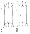
- FIGS. 2 and 3 show cross sections through tubular materials 4, which were provided by the method according to the invention with longitudinal seams. That in the Fig. 2 shown material 4 is usually produced as a tubular film and wound up after the accident with gussets 30 to a winding 3. In the station 28 for attaching longitudinal seams, the tubular material 4 was provided at its outer edges 31 with edge seams 29. This in Fig. 3 shown tubular material 4 differs from that in Fig. 2 shown material 4 by a longitudinal seam 32, with which the two edge regions of a flat film for the purpose of forming a hose are interconnected. In general, the joining is done by welding, but in practice, other joining methods such as the sealing or the application of adhesives or Holtmelt be applied.
Landscapes
- Engineering & Computer Science (AREA)
- Mechanical Engineering (AREA)
- Making Paper Articles (AREA)
- Basic Packing Technique (AREA)
- Bag Frames (AREA)
- Supplying Of Containers To The Packaging Station (AREA)
Description
- Die Erfindung betrifft ein Verfahren zur Herstellung und Befüllung von Säcken nach dem Oberbegriff des Anspruchs 1 und eine Vorrichtung zur Herstellung und Befüllung von Säcken nach dem Oberbegriff des Anspruchs 13.
- Säcke werden unter anderem von so genannten "Form, Fill and Seal"-Maschinen (im Folgenden FFS-Maschinen) hergestellt.
- Eine Art an FFS-Maschinen zeigt die Patentschrift
US 6,428,456 B1 , die bei der Herstellung von Beutel von einer flexiblen, flachen Bahn ausgeht, die über eine Ziehschulter, welche am oberen Ende eines Rohres angeordnet ist, zunächst zu einem offenen Schlauch zusammengelegt wird. Um einen dauerhaften Schlauch zu bilden, sind die überlappenden Seitenbereiche der Bahn miteinander zu verschweißen. Unterhalb des Rohres wird in einem weiteren Bearbeitungsschritt der Boden des späteren Beutels gebildet, indem eine Querverschlussnaht angebracht wird. Dann wird der Beutel durch das Rohr befüllt, verschlossen und vom nachfolgenden Schlauch abgetrennt. Diese Art der Herstellung wird vor allem zum Abfüllen von geringen Produktgewichten verwendet, wie sie typisch für die Nahrungsmittelindustrie sind. - Die Maschinen, mit der sich die vorliegende Erfindung beschäftigt und welche unter anderem in den Druckschriften
DE 199 33 486 ,EP 534 062 DE 44 23 964 ,DE 199 20 478 A1 undDE 199 36 660 A1 gezeigt sind, verfügen über Abwicklungsvorrichtungen, auf denen bereits vorgefertigte Schläuche gespeichert sind. Von diesen Abwicklungsvorrichtungen wird der Schlauch abgewickelt und zu Schlauchstücken vereinzelt. In weiteren Arbeitsgängen werden in der Regel Schlauchböden gebildet, Füllgut in den entstandenen Sack gefüllt sowie der Sack verschlossen. In der Regel wird mit diesen Maschinen Schüttgut abgefüllt. - In der Regel werden zur Verarbeitung an den FFS-Maschinen durch Blasfolienextrusion Folienschläuche gebildet, deren Format (hier deren Umfang) mit dem des gebildeten Sackes übereinstimmt. Diese Vorgehensweise führt jedoch dazu, dass schon an den Extrusionsanlagen relativ häufig teure Formatwechsel vorgenommen werden müssen, um unterschiedliche Sackformate realisieren zu können. Darüber hinaus sind die zur Sackbildung benötigten Formate relativ klein und lassen sich relativ unwirtschaftlich erzeugen. Blasfolienanlagen größeren Formats erzeugen gleiche Folie zu geringeren Kosten pro Flächeneinheit.
- Daher ist des Öfteren versucht worden, zunächst sehr breite Folienbahnen durch Flachfolienextrusion oder durch Blasfolienextrusion an Anlagen großen Formats herzustellen, wobei in der Regel, ebenfalls in erster Linie aus Kostengründen, Blasfolienextrusionsanlagen bevorzugt wurden. Die entstandenen Folienschläuche oder Folienbahnen großen Formats wurden dann durch formatgerechtes Schneiden zu Flachfolienbahnen weiter verarbeitet.
- Daraufhin wurde eine dieser flachgelegten Folienbahnen zu einem Schlauch zusammengelegt und durch eine Längsschweißnaht zu einem Schlauch verbunden. Der Einsatz der dargestellten Maschinen beschränkt sich jedoch in erster Linie auf industrielle Anwendungen, wie die Absackung von Farbstoffen, Kunststoffgranulat, Düngemittel und andere Massengüter.
- Konsumgüter, die über den Einzelhandel vertrieben werden, werden in aller Regel in höherwertigen Säcke transportiert und vertrieben. So ist es zum Beispiel bekannt, Seitenfaltenbeutel oder -säcke aus Schlauchstücken herzustellen, welche aus mehreren Folienabschnitten gebildet sind. In der Regel werden zu diesem Zweck die Ränder der jeweiligen Folienabschnitte miteinander verschweißt. Dieser Vorgang wird zwischen Schweißbacken vorgenommen, die das zu verschweißende Material während des Schweißvorgangs arretieren.
- In der Regel werden auf diese Weise bereits Schlauchstücke hergestellt, deren Länge der der späteren Säcke entspricht. In anderen Fällen werden die gebildeten Schlauchstücke direkt nach ihrer Herstellung auf die spätere Sacklänge gebracht und in vereinzelter Form Sackbildungs- und Befülleinrichtungen zugeführt. Diese Art der Bildung hochwertiger Säcke ist zum Beispiel im Petfood-Bereich wohlbekannt. Hier wird auf Seitenfaltensäcke Wert gelegt, die an jeder ihrer Außenfalten über Kantennähte verfügen. Diesen Säcken wird eine größere Stabilität, insbesondere aber ein besseres Aussehen nachgesagt. In der Regel werden diese Säcke hergestellt, indem zunächst ein Schlauch durch eine Längsschweißung von Flachfolie hergestellt wird. Dieser Schlauch wird zu Schlauchstücken vereinzelt und mit weiteren Längsschweißnähten beaufschlagt.
- Allerdings ist sowohl der Transport vereinzelter Schlauchstücke als auch das spätere Einbringen derselben in einen Sackbildungs- und Befüllungsprozess aufwändig. Dieses erfolgt in der Regel mit Rotationsanlegern oder anderen Saugvorrichtungen, welche die Schlauchstücke einzeln greifen und der Sackbildungsvorrichtung zuführen. Solche Vorrichtungen sind teuer und störungsanfällig.
- Daher besteht die Aufgabe der vorliegenden Erfindung darin, ein FFS-Verfahren und eine FFS-Vorrichtung vorzuschlagen, nach dem beziehungsweise mit der kostengünstige Säcke herstellbar und befüllbar sind, die eine größere Stabilität aufweisen.
- Diese Aufgabe wird dadurch gelöst, dass das schlauchförmige Material in der Sackbildungsvorrichtung mit Längsnähten versehen wird, die sich zumindest über einen großen Teil der Säcke erstrecken, während sich das schlauchförmige Material noch im flachliegenden Zustand befindet.
- Der Begriff Nähte oder Längsnähte ist in diesem Zusammenhang als Oberbegriff für Verbindungsnähte und alle weiteren Nähte, wozu auch die Kantennähte zählen, zu verstehen, wobei insbesondere die Kantennähte eben nicht die Aufgabe haben, die Stoßstellen von Flachfolien zusammenzuhalten wie Verbindungsnähte. Die Funktion der Kantennähte besteht in der dargestellten Stabilisierung des Sackes, die insbesondere die Ausprägung einer annähernd quaderartigen Form in seinem befüllten Zustand unterstützt und damit das Stapeln solcher Säcke erleichtert.
- Um nun das schlauchförmige Material zu Säcken zu verarbeiten, ist es vorteilhaft, zunächst Sackböden durch Querschweißungen zu bilden. Querschweißungen lassen sich besonders einfach am noch schlauchförmigen Material bilden, da dieses Material noch an verschiedenen Stellen von Greifern oder Zangen oder ähnlichen Haltemitteln ergriffen werden kann.
- Aus gleichem Grund bietet es sich an, auch die Längsnähte zu bilden, bevor das Material zu Schlauchstücken vereinzelt wird. Dabei kann das Bilden der Längsnähte noch vor dem Bilden der Querschweißnähte erfolgen. Zudem kann das schlauchförmige Material vor oder nach dem Bilden der Längsnähte mit Diagonalabschweißungen versehen werden, welche an den späteren Säcken so genannte Eckabschweißungen bilden, die die Stabilität der Säcke weiter erhöhen.
- In einer vorteilhaften Weiterbildung der Erfindung ist vorgesehen, dass die Säcke in der Sackbildungsvorrichtung auch befüllt werden. Ein Schlauchstück, welches zum Zwecke der Bildung von Längs- oder Quernähten durch Haltemittel gehalten wird, kann von diesen oder weiteren Haltemitteln einer Füllvorrichtung zugeführt werden. Das zeitintensive Ablegen, Speichern und Wiederaufnehmen der Schlauchstücke entfällt damit. Den Transport durch die Sackbildungsvorrichtung übernehmen dabei vorteilhafterweise als Greifer ausgeführte Haltemittel. Die Greifer können jeweils paarweise vorhanden sein, wobei sie die Schlauchstücke seitlich im Bereich des oberen Randes umgreifen. Dabei kann es nötig sein, das Schlauchstück von einem Greiferpaar zu einem anderen Greiferpaar zu übergeben. Zu diesem Zweck sind Transferpositionen vorgesehen, an denen kurzzeitig beide Greiferpaare das Schlauchstück halten.
Der Transport der Schlauchstücke oder der Säcke erfolgt dabei zumindest zur Hälfte in horizontaler Richtung, d. h. dass bei jeder Bewegung der Schlauchstücke oder der Säcke die horizontale Strecke die vertikale Strecke übertrifft. - In der Sackbildungsvorrichtung kann das schlauchförmige Material während der Stillstandsphasen des intermittierenden Transportes mit Längsnähten versehen werden. Grundsätzlich können Längsnähte auch während des Transportes des schlauchförmigen Materials angebracht werden, jedoch können in erstem Fall die Längsnähte über verschiedene Zeiträume gebildet werden, wobei die Zeiträume zwar nach oben durch die reziproke Taktgeschwindigkeit begrenzt, aber ansonsten variabel sind. Werden die Längsnähte beispielsweise durch Schweißungen gebildet, kann die Schweißdauer, etwa in Abhängigkeit von der Materialstärke, gewählt werden.
- Weitere Ausführungsbeispiele der Erfindung gehen aus der gegenständlichen Beschreibung und den Ansprüchen hervor. Die der gegenständlichen Beschreibung zugrunde liegenden Figuren zeigen:
- Fig. 1.:
- eine Vorrichtung zum Herstellen und Befüllen von Säcken, mit der sich das erfindungsgemäße Verfahren durchführen lässt.
- Fig. 2.:
- einen Querschnitt eines schlauchförmigen Materials, das mit Längsnähten nach dem erfindungsgemäßen Verfahren versehen wurde.
- Fig. 3.:
- einen Querschnitt eines weiteren schlauchförmigen Materials, das mit Längsnähten nach dem erfindungsgemäßen Verfahren versehen wurde.
- Diese Vorrichtung 1 umfasst einen Tragarm 2, auf welchem ein Wickel 3 mit schlauchförmiger Folie 4 aufliegt. Die schlauchförmige Folie 4 weist nicht dargestellte Seitenfalten auf. Die Transportwalzen 5, die zum Teil auch angetrieben sein können, sorgen für eine, in der Regel kontinuierliche, Abwicklung der schlauchförmigen Folie 4. Der durch eine Kolben-Zylinder-Einheit 10 mit einer Last beaufschlagte Hebel 9, welcher eine Umlenkwalze 6 trägt und insgesamt häufig als Tänzereinrichtung bezeichnet wird, und die Transportwalze 7, 8 und das Vorschubrollenpaar 15 sorgen insgesamt auf an sich bekannte Weise dafür, dass die schlauchförmige Folie 4 auf ihrem weiteren Transportweg taktweise intermittierend weiterbewegt wird. Im weiteren Verlauf durchläuft die schlauchförmige Folie 4 eine Station 28 zum Anbringen von Längsnähten. Auf nicht näher dargestellte Weise werden an den Außenkanten der Seitenfalten der schlauchförmigen Folie 4 Längsnähte angebracht, wobei die Arbeitslänge der Station 28 zumindest die Länge der späteren Säcke aufweist. Die Längsnähte werden in der Regel durch Anbringen von Schweißungen während der Stillstandsphasen des intermittierenden Transports erzeugt. Über weitere Transportwalzen 8 wird die mit Längsnähten versehene schlauchförmige Folie 4 zu einer Eckabschweißstation 11 und einer Kühlstation 12 gefördert.
- Mit dem Vorschubrollenpaar 15 wird die schlauchförmige Folie 4 durch die Schweißbacken einer Querschweißstation 13 und durch eine Querschneidestation 16 hindurch geschoben. Die Werkzeuge der Querschweißstation 13 und der Querschneidestation 16 können auf nicht näher beschriebene Weise, beispielsweise durch eine Parallelogrammanordnung 14, in Ebenen orthogonal zur Vorschubrichtung der schlauchförmigen Folie 4 auf diese zu und von dieser weg bewegt werden. Nachdem die Greifer 17 die schlauchförmige Folie 4 ergriffen haben, wird oberhalb der Greifer 17 ein Schlauchstück 18 in der Querschneidestation 16 von der schlauchförmigen Folie 4 abgetrennt. Zeitgleich wird oberhalb der Schnittkante an der schlauchförmigen Folie in der Querschweißstation 13 eine Querschweißung angebracht, welche den Boden des im nächsten Arbeitstakt der Vorrichtung 1 zu bildenden Schlauchstücks 18 darstellt. Die Bodenherstellung kann jedoch nicht nur, auch wenn vorzugsweise, durch eine Querschweißung erfolgen, sondern es sind auch weitere Fügeverfahren, etwa das Kleben, denkbar.
- Die Greifer 17 befördern das Schlauchstück 18 zu einem Übergabepunkt, an dem weitere Greifer 19 das Schlauchstück 18 erfassen und zu einer Füllstation 20 transportieren. Dort wird das Schlauchstück 18 an stationäre Greifer 21 übergeben und von den Saugern 22 geöffnet, so dass das Füllgut, welches durch den Füllstutzen 23 geleitet wird, in das Schlauchstück 18 gelangen kann. Das Schlauchstück liegt dabei mit seinem unteren Ende auf einem Transportband 24 auf, so dass das Schlauchstück 18 während des Befüllvorganges nicht übermäßig entlang seiner Längskanten belastet wird. Weitere Greifer 25 befördern das befüllte Schlauchstück zur Kopfnahtschweißstation 26, in der das Schlauchstück 18 mit einer Kopfschweißnaht verschlossen wird und so einen fertigen Sack 27 bildet. Auch das Verschließen des Schlauchstücks 18 in seinem Kopfbereich kann durch ein anderes Fügeverfahren erfolgen. Der fertige Sack wird von dem Transportband 24 aus der Vorrichtung 1 heraus geführt.
- Die
Figuren 2 und 3 zeigen Querschnitte durch schlauchförmige Materialien 4, die nach dem erfindungsgemäßen Verfahren mit Längsnähten versehen wurden. Das in derFig. 2 gezeigte Material 4 wird in der Regel als Schlauchfolie produziert und nach dem Versehen mit Seitenfalten 30 zu einem Wickel 3 aufgewickelt. In der Station 28 zum Anbringen von Längsnähten wurde das schlauchförmige Material 4 an seinen Außenkanten 31 mit Kantennähten 29 versehen. Das inFig. 3 gezeigte schlauchförmige Material 4 unterscheidet sich von dem inFig. 2 gezeigten Material 4 durch eine Längsnaht 32, mit welcher die beiden Randbereiche einer Flachfolie zwecks Bildung eines Schlauches miteinander verbunden werden. In der Regel erfolgt das Verbinden durch Verschweißen, jedoch werden in der Praxis auch andere Fügeverfahren wie das Siegeln oder das Aufbringen von Klebstoffen oder Holtmelt angewandt. Nach der derartigen Bildung eines schlauchförmigen Materials 4, das ebenfalls mit Seitenfalten 30 versehen werden kann, wird das schlauchförmige Material 4 zu einem Wickel aufgewickelt.Bezugszeichenliste 1 Vorrichtung zum Herstellen und Befüllen von Säcken 2 Tragarm 3 Wickel 4 Folie 5 Transportwalze 6 Umlenkwalze 7 Transportwalze 8 Transportwalze 9 Hebel 10 Kolben-Zylinder-Einheit 11 Eckabschweißstation 12 Kühlstation 13 Querschweißstation 14 Parallelogrammanordnung 15 Vorschubrollenpaar 16 Querschneidestation 17 Greifer 18 Schlauchstück 19 Greifer 20 Füllstation 21 Stationärer Greifer 22 Sauger 23 Füllstutzen 24 Transportband 25 Greifer 26 Kopfnahtschweißstation 27 Sack 28 Station zum Anbringen von Längsnähten 29 Kantennähte 30 Seitenfalten 31 Außenkanten 32 Längsnaht
Claims (16)
- Verfahren zur Herstellung und Befüllung von Säcken (27) mit zumindest vier Längsnähten (29),
dadurch gekennzeichnet,- dass das Material, aus dem die Säcke bestehen, in Form schlauchförmigen Materials (4) von einer Abwicklungsvorrichtung (2,3,5) einer Sackbildungsvorrichtung (1) zugeführt wird und- dass das schlauchförmige Material (4) in der Sackbildungsvorrichtung (1) mit Längsnähten (29) versehen wird, die sich zumindest über einen großen Teil der Säcke (27) erstrecken. - Verfahren nach Anspruch 1,
dadurch gekennzeichnet, dass
die Sackbildungsvorrichtung (1) die Sackbildung vornimmt, indem sie Sackböden in dem schlauchartigen Material (4) durch Querschweißungen bildet. - Verfahren nach einem der vorstehenden Ansprüche
dadurch gekennzeichnet, dass
die Längsnähte (29) gebildet werden, bevor das schlauchförmige Material (4) zu Schlauchstücken (18) vereinzelt wird. - Verfahren nach einem der vorstehenden Ansprüche,
dadurch gekennzeichnet, dass
die Sackbildungsvorrichtung (1) auch die Befüllung der Säcke (27) vornimmt, indem sie Füllgut in die Säcke (27) abfüllt. - Verfahren nach einem der vorstehenden Ansprüche,
dadurch gekennzeichnet, dass
die Schlauchstücke (18) oder Säcke (27) während zumindest eines Teils ihres Weges in der Sackbildungsvorrichtung (1) durch Greifer (17,19,25) transportiert werden. - Verfahren nach dem vorstehenden Anspruch,
dadurch gekennzeichnet, dass
die Greifer (17,19,25) die Schlauchstücke (18) oder die Säcke (27) im Bereich ihrer Außenkanten (31) umgreifen, wobei das Schlauchstück (18) oder der Sack (27) herunterhängt. - Verfahren nach einem der vorstehenden Ansprüche,
dadurch gekennzeichnet, dass
die Schlauchstücke (18) oder Säcke (27) zumindest zur Hälfte horizontal transportiert werden. - Verfahren nach einem der vorstehenden Ansprüche,
dadurch gekennzeichnet, dass
das schlauchförmige Material (4) in der Sackbildungsvorrichtung (1) während der Stillstandsphasen des intermittierenden Transportes mit Längsnähten (29) versehen wird. - Verfahren nach einem der vorstehenden Ansprüche,
dadurch gekennzeichnet, dass
die Längsnähte (29) gekühlt werden, bevor der Sack (27) befüllt wird. - Verfahren nach einem der vorstehenden Ansprüche,
dadurch gekennzeichnet, dass das schlauchförmige Material (4) bereits vor dem Anbringen von Längsnähten (29) in der Sackbildungsvorrichtung (1) über zumindest eine Längsschweißung (32) verfügt, mit welcher zumindest eine Flachfolienbahn zu schlauchförmigem Material verbunden ist. - Verfahren nach einem der vorstehenden Ansprüche,
dadurch gekennzeichnet,- dass das schlauchförmige Material (4) ein Seitenfaltenschlauch ist, und- dass die Schweißnähte an den Außenfalten des Seitenfaltenschlauches angebracht werden. - Verfahren nach einem der vorstehenden Ansprüche,
dadurch gekennzeichnet, dass
das schlauchförmige Material (4) mit Diagonalabschweißungen versehen wird, bevor es (4) mit Längsnähten (29) versehen wird. - Vorrichtung (1) zur Herstellung und Befüllung von Säcken mit zumindest vier Längsnähten,
gekennzeichnet durch- eine Abwicklungsvorrichtung (2,3,5), von welcher das Material (4), aus dem die Säcke bestehen, in Form schlauchförmigen Materials (4) einer Sackbildungsvorrichtung (1) zugeführt wird, und- eine Längsschweißeinrichtung (28), welche das schlauchförmige Material (4) in der Sackbildungsvorrichtung (1) mit Längsnähten versieht, die sich zumindest über einen großen Teil der Säcke (27) erstrecken. - Vorrichtung (1) nach dem vorstehenden Anspruch,
gekennzeichnet durch
eine Tänzereinrichtung (6,9,10) zwischen Abwicklungsvorrichtung (2,3,5) und Längsschweißeinrichtung (28). - Vorrichtung (1) nach einem der vorstehenden Ansprüche,
gekennzeichnet durch
eine Kühleinrichtung (12) für die Längsnähte, welche in der Transportrichtung des schlauchförmigen Materials (4) eine Länge von mindestens 30 cm aufweist. - Vorrichtung (1) nach einem der vorstehenden Ansprüche,
gekennzeichnet durch
eine Kühleinrichtung (12) für die Längsnähte, welche in der Transportrichtung des schlauchförmigen Materials (4) eine Länge von mindestens 45 cm aufweist.
Priority Applications (1)
| Application Number | Priority Date | Filing Date | Title |
|---|---|---|---|
| PL05762405T PL1773576T6 (pl) | 2004-07-16 | 2005-06-30 | Sposób i urządzenie do wytwarzania i napełniania worków |
Applications Claiming Priority (2)
| Application Number | Priority Date | Filing Date | Title |
|---|---|---|---|
| DE102004034489A DE102004034489A1 (de) | 2004-07-16 | 2004-07-16 | Verfahren und Vorrichtung zur Herstellung und Befüllung von Säcken |
| PCT/EP2005/007157 WO2006007960A1 (de) | 2004-07-16 | 2005-06-30 | Verfahren und vorrichtung zur herstellung und befüllung von säcken |
Publications (3)
| Publication Number | Publication Date |
|---|---|
| EP1773576A1 EP1773576A1 (de) | 2007-04-18 |
| EP1773576B1 true EP1773576B1 (de) | 2009-09-02 |
| EP1773576B3 EP1773576B3 (de) | 2012-05-09 |
Family
ID=34972736
Family Applications (1)
| Application Number | Title | Priority Date | Filing Date |
|---|---|---|---|
| EP05762405A Not-in-force EP1773576B3 (de) | 2004-07-16 | 2005-06-30 | Verfahren und vorrichtung zur herstellung und befüllung von säcken |
Country Status (8)
| Country | Link |
|---|---|
| US (1) | US7770362B2 (de) |
| EP (1) | EP1773576B3 (de) |
| JP (2) | JP2008513299A (de) |
| AT (1) | ATE441517T1 (de) |
| DE (2) | DE102004034489A1 (de) |
| ES (1) | ES2333136T7 (de) |
| PL (1) | PL1773576T6 (de) |
| WO (1) | WO2006007960A1 (de) |
Families Citing this family (16)
| Publication number | Priority date | Publication date | Assignee | Title |
|---|---|---|---|---|
| ATE416999T1 (de) * | 2005-04-15 | 2008-12-15 | Regath Hb | Flexible verpackung und verfahren zu ihrer herstellung |
| DE102005018545B4 (de) * | 2005-04-20 | 2015-01-15 | Windmöller & Hölscher Kg | Verfahren und System zur Herstellung und Befüllung von Beuteln oder Säcken |
| SE531357C2 (sv) * | 2007-09-28 | 2009-03-10 | Ecolean Res & Dev As | Anordning och metod för hantering av en förpackning |
| AT10632U1 (de) * | 2008-04-07 | 2009-07-15 | Statec Anlagentechnik Gmbh | Vorrichtung zum abfüllen von säcken |
| SE532636C2 (sv) * | 2008-07-02 | 2010-03-09 | Ecolean Res & Dev As | Anordning för fyllning av förpackningar |
| DE102010028394B4 (de) | 2010-04-29 | 2019-05-23 | Windmöller & Hölscher Kg | Verfahren und eine Vorrichtung zur Herstellung und Befüllung von Verpackungsmitteln |
| DE102010049369A1 (de) * | 2010-10-26 | 2012-04-26 | Haver & Boecker Ohg | Sack und Verfahren zum Füllen eines Sacks |
| US9505504B2 (en) | 2011-02-18 | 2016-11-29 | Pouch Pac Innovations, Llc | Apparatus for the two stage filling of flexible pouches |
| DE102011015491B3 (de) * | 2011-03-29 | 2012-06-06 | Windmöller & Hölscher Kg | Verfahren zum Querschweißen von Kunststoffschläuchen und Vorrichtung zum Formen und Schließen von Säcken |
| US9944037B2 (en) * | 2011-05-12 | 2018-04-17 | Pouch Pac Innovations, Llc | Apparatus for simultaneously separating a plurality of pouches, transferring the pouches and method of same |
| DE102013105549B3 (de) * | 2013-05-29 | 2014-07-03 | Windmöller & Hölscher Kg | Kühlvorrichtung für die Kühlung einer Schweißnaht an einer Seitenfalte eines Folienmaterials in einer Sackfüllanlage |
| WO2015166445A1 (en) * | 2014-05-02 | 2015-11-05 | Robopac S.P.A. | Gripping apparatus for a wrapping machine |
| EP3323741A1 (de) * | 2016-11-22 | 2018-05-23 | Payper, S.A. | Kühlvorrichtung zum kühlen von abdichtungen in einer folie in einer form-füll-siegelmaschine |
| DE202016008986U1 (de) | 2016-11-22 | 2021-06-10 | Payper S.A. | Kühlvorrichtung zum Kühlen von Verschlüssen in einer Folie in einer Form-, Füll- und Verschlussmaschine |
| US11498712B2 (en) * | 2018-01-11 | 2022-11-15 | Windmöller & Hölscher Kg | Filling device and method for filling upwardly open packaging containers, and form-fill-seal device |
| DE102018206356A1 (de) * | 2018-02-19 | 2019-10-17 | Windmöller & Hölscher Kg | Fülleinrichtung und Verfahren zum Befüllen von Säcken mit jeweils einem unverschlossenen oberen Ende |
Family Cites Families (34)
| Publication number | Priority date | Publication date | Assignee | Title |
|---|---|---|---|---|
| DE1278323B (de) * | 1961-05-04 | 1968-09-19 | Hesser Ag Maschf | Vorrichtung zum Herstellen von Weichbeuteln und zu deren UEberfuehren an eine Beutelfuell- und Schliessmaschine |
| US3462067A (en) * | 1968-07-25 | 1969-08-19 | Diamond Shamrock Corp | Self-supporting plastic container |
| US3739977A (en) * | 1971-06-22 | 1973-06-19 | J Shapiro | Plastic market bag |
| US3915077A (en) * | 1974-11-27 | 1975-10-28 | Lee Lafleur | Bag forming apparatus |
| DE2519253C3 (de) * | 1975-04-30 | 1979-10-25 | Haver & Boecker, 4740 Oelde | Maschine zum Verpacken von Schüttgut in Seitenfaltensäcken aus Kunststoff |
| CA1126150A (en) * | 1978-09-12 | 1982-06-22 | Frederick W. Beer | Package and automatic method of forming same |
| DE3118866C2 (de) * | 1981-05-13 | 1984-04-12 | Haver & Boecker, 4740 Oelde | "Maschine zum Füllen und Verschließen von Säcken aus Kunststoff, vorzugsweise von Seitenfaltensäcken oder Flachsäcken" |
| DE3376637D1 (en) * | 1982-10-16 | 1988-06-23 | Johnsen Jorgensen Jaypak | Bag apparatus |
| DE3514714A1 (de) * | 1985-04-24 | 1986-10-30 | Rovema Verpackungsmaschinen GmbH, 6301 Fernwald | Verfahren zur herstellung von verpackungen und verpackungsmaschine |
| US4835948A (en) * | 1986-03-03 | 1989-06-06 | Basic Packaging Systems, Inc. | Bag filling machine |
| EP0290879B1 (de) * | 1987-05-11 | 1992-11-11 | WindmÀ¶ller & Hölscher | Vorrichtung zum Befüllen und Verschliessen einseitig offener Säcke |
| DE3819040A1 (de) * | 1988-06-04 | 1989-12-07 | Fix Peter Steimel Gmbh & Co Kg | Verfahren und vorrichtung zur herstellung, befuellung und zuschweissung von kunststoffsaecken |
| JPH0628928B2 (ja) * | 1988-06-25 | 1994-04-20 | 雅雄 大島 | 背貼部のない熱接着ガセット包装袋の連続製造方法及び連続製造装置 |
| DE4131646A1 (de) | 1991-09-23 | 1993-03-25 | Windmoeller & Hoelscher | Verfahren zum herstellen, befuellen und verschliessen von saecken |
| JPH0664611A (ja) * | 1992-08-12 | 1994-03-08 | Toyo Jidoki Co Ltd | 自動充填包装機 |
| IT1263250B (it) * | 1992-10-27 | 1996-08-05 | Macchina automatica per formare, riempire e sigillare sacchi e simili. | |
| ES2113721T3 (es) * | 1993-11-05 | 1998-05-01 | Ferruccio Patelli | Metodo para la fabricacion de envases para productos liquidos, especialmente para productos alimentarios liquidos, y un envase obtenido por medio de este metodo. |
| DE4423964C1 (de) | 1994-07-07 | 1995-12-07 | Windmoeller & Hoelscher | Vorrichtung zum Befüllen von Säcken |
| DE19603371B4 (de) * | 1996-01-31 | 2006-12-14 | Rovema - Verpackungsmaschinen Gmbh | Schlauchbeutelmaschine mit einer asymmetrischen Formschulter zur Herstellung von Schlauchbeuteln |
| US5618254A (en) * | 1995-04-27 | 1997-04-08 | Super Sack Mfg. Corp. | Gusseted bulk bag liner and method of manufacture |
| JPH09277406A (ja) * | 1996-04-09 | 1997-10-28 | Totani Giken Kogyo Kk | 製袋機 |
| US5768863A (en) * | 1997-03-21 | 1998-06-23 | Slidell, Inc. | Gusset control mechanism for bag closing machines |
| US5944251A (en) * | 1998-01-07 | 1999-08-31 | Custom Packaging Systems, Inc. | Form fit container liner |
| IT1305236B1 (it) * | 1998-01-30 | 2001-04-19 | Burgopack Stampa Trasformazione Imballaggi Spa | Apparecchiatura per formare contenitori a tubo a spigoli rinforzati econtenitore ottenuto con l'apparecchiatura. |
| AP1295A (en) * | 1998-06-09 | 2004-09-03 | Lance John Muller | Liner bag for flexible bulk container. |
| DE19920478C2 (de) * | 1999-05-04 | 2001-05-03 | Windmoeller & Hoelscher | Vorrichtung zum Herstellen und vorzugsweise auch zum Befüllen und Verschließen von Säcken aus thermoplastischem Kunststoff |
| DE19933486C2 (de) | 1999-05-04 | 2001-06-13 | Windmoeller & Hoelscher | Vorrichtung zum Befüllen und Verschließen von Säcken |
| DE19964295C2 (de) * | 1999-05-04 | 2002-12-19 | Windmoeller & Hoelscher | Vorrichtung zum Herstellen, Befüllen und Verschliessen von Säcken |
| DE19936660C2 (de) | 1999-05-04 | 2002-10-24 | Windmoeller & Hoelscher | Vorrichtung zum Herstellen, Befüllen und Verschließen von Säcken |
| JP4079634B2 (ja) * | 2001-12-06 | 2008-04-23 | 大日本印刷株式会社 | チャック付袋の製袋方法及び製袋充填方法 |
| JP4060077B2 (ja) * | 2001-12-28 | 2008-03-12 | 株式会社彫刻プラスト | ヒダ付き扁平袋の製造方法 |
| JP2003335347A (ja) * | 2002-05-15 | 2003-11-25 | Koji Onuma | 自立性扁平袋及びその製造方法 |
| US20040013325A1 (en) * | 2002-07-22 | 2004-01-22 | Gavin Cook | Bag for flowable materials |
| DE102004038006A1 (de) * | 2004-08-04 | 2006-03-02 | Windmöller & Hölscher Kg | Vorrichtung und Verfahren zur Herstellung und Befüllung von Säcken |
-
2004
- 2004-07-16 DE DE102004034489A patent/DE102004034489A1/de not_active Ceased
-
2005
- 2005-06-30 US US11/628,653 patent/US7770362B2/en not_active Expired - Fee Related
- 2005-06-30 WO PCT/EP2005/007157 patent/WO2006007960A1/de active Application Filing
- 2005-06-30 ES ES05762405T patent/ES2333136T7/es active Active
- 2005-06-30 EP EP05762405A patent/EP1773576B3/de not_active Not-in-force
- 2005-06-30 JP JP2007520706A patent/JP2008513299A/ja active Pending
- 2005-06-30 AT AT05762405T patent/ATE441517T1/de active
- 2005-06-30 DE DE502005008062T patent/DE502005008062D1/de active Active
- 2005-06-30 PL PL05762405T patent/PL1773576T6/pl unknown
-
2011
- 2011-11-25 JP JP2011258056A patent/JP2012062119A/ja active Pending
Also Published As
| Publication number | Publication date |
|---|---|
| ATE441517T1 (de) | 2009-09-15 |
| EP1773576B3 (de) | 2012-05-09 |
| US20070289262A1 (en) | 2007-12-20 |
| WO2006007960A1 (de) | 2006-01-26 |
| PL1773576T3 (pl) | 2010-02-26 |
| JP2012062119A (ja) | 2012-03-29 |
| EP1773576A1 (de) | 2007-04-18 |
| US7770362B2 (en) | 2010-08-10 |
| JP2008513299A (ja) | 2008-05-01 |
| PL1773576T6 (pl) | 2012-10-31 |
| DE502005008062D1 (de) | 2009-10-15 |
| ES2333136T3 (es) | 2010-02-17 |
| ES2333136T7 (es) | 2012-11-19 |
| DE102004034489A1 (de) | 2006-04-20 |
Similar Documents
| Publication | Publication Date | Title |
|---|---|---|
| EP1773576B1 (de) | Verfahren und vorrichtung zur herstellung und befüllung von säcken | |
| EP2563672B1 (de) | Verfahren und eine vorrichtung zur herstellung und befüllung von verpackungsmitteln | |
| DE19964295C2 (de) | Vorrichtung zum Herstellen, Befüllen und Verschliessen von Säcken | |
| EP2447166B1 (de) | Vorrichtung und Verfahren zum Füllen eines Sacks | |
| EP1623926B1 (de) | Vorrichtung und Verfahren zur Herstellung und Befüllung von Säcken | |
| DE10306615B4 (de) | Verfahren zur Herstellung von Säcken | |
| EP3551446B1 (de) | Sackherstellvorrichtung und verfahren | |
| EP2739455B1 (de) | Verfahren und vorrichtung zum herstellen, befüllen und verschliessen von säcken sowie ein sack | |
| DE102018206356A1 (de) | Fülleinrichtung und Verfahren zum Befüllen von Säcken mit jeweils einem unverschlossenen oberen Ende | |
| DE602005001899T2 (de) | Verfahren und Vorrichtung zum Versehen von Grifföffnungen in Beuteln, und Beutel mit zwei Grifföffnungen | |
| EP1201539A1 (de) | Vorrichtung zum Herstellen und vorzugsweise auch zum Befüllen und Verschliessen von Säcken aus thermoplastichem Kunststoff | |
| DE102013100131A1 (de) | Verfahren zum Herstellen von Säcken | |
| DE202004021466U1 (de) | Vorrichtung zur Herstellung und Befüllung von Säcken | |
| EP1597054B1 (de) | Schlauch sowie vorrichtung und verfahren zur herstellung desselben | |
| DE102011015491B3 (de) | Verfahren zum Querschweißen von Kunststoffschläuchen und Vorrichtung zum Formen und Schließen von Säcken | |
| DE10217397A1 (de) | Verfahren zum Befüllen von Säcken | |
| DE102005018545A1 (de) | Verfahren zur Herstellung und Befüllung von Beuteln oder Säcken | |
| DE2362613A1 (de) | Verfahren und vorrichtung zum herstellen von kunststoffseitenfaltenventilsaecken | |
| DE1240726B (de) | Verfahren und Vorrichtung zum Herstellen von Beuteln od. dgl. aus einer einseitig eine warm verschweissbare Flaeche aufweisenden Materialbahn | |
| EP2268548B1 (de) | Vorrichtung zum abfüllen von säcken | |
| DE1761580B (de) | Verfahren und Vorrichtung zum Bilden eines Füllventiles an Kunststoffsäcken aus quergeförderten Seitenfaltenschlauchabschnitten | |
| DE19539465A1 (de) | Vertikales Form-Füll- und Siegelverfahren zur Herstellung von Fließmittelpackungen |
Legal Events
| Date | Code | Title | Description |
|---|---|---|---|
| PUAI | Public reference made under article 153(3) epc to a published international application that has entered the european phase |
Free format text: ORIGINAL CODE: 0009012 |
|
| 17P | Request for examination filed |
Effective date: 20070216 |
|
| AK | Designated contracting states |
Kind code of ref document: A1 Designated state(s): AT BE BG CH CY CZ DE DK EE ES FI FR GB GR HU IE IS IT LI LT LU MC NL PL PT RO SE SI SK TR |
|
| DAX | Request for extension of the european patent (deleted) | ||
| 17Q | First examination report despatched |
Effective date: 20080214 |
|
| GRAP | Despatch of communication of intention to grant a patent |
Free format text: ORIGINAL CODE: EPIDOSNIGR1 |
|
| GRAS | Grant fee paid |
Free format text: ORIGINAL CODE: EPIDOSNIGR3 |
|
| GRAA | (expected) grant |
Free format text: ORIGINAL CODE: 0009210 |
|
| AK | Designated contracting states |
Kind code of ref document: B1 Designated state(s): AT BE BG CH CY CZ DE DK EE ES FI FR GB GR HU IE IS IT LI LT LU MC NL PL PT RO SE SI SK TR |
|
| REG | Reference to a national code |
Ref country code: CH Ref legal event code: EP |
|
| REG | Reference to a national code |
Ref country code: IE Ref legal event code: FG4D Free format text: LANGUAGE OF EP DOCUMENT: GERMAN |
|
| REF | Corresponds to: |
Ref document number: 502005008062 Country of ref document: DE Date of ref document: 20091015 Kind code of ref document: P |
|
| PG25 | Lapsed in a contracting state [announced via postgrant information from national office to epo] |
Ref country code: SE Free format text: LAPSE BECAUSE OF FAILURE TO SUBMIT A TRANSLATION OF THE DESCRIPTION OR TO PAY THE FEE WITHIN THE PRESCRIBED TIME-LIMIT Effective date: 20090902 Ref country code: LT Free format text: LAPSE BECAUSE OF FAILURE TO SUBMIT A TRANSLATION OF THE DESCRIPTION OR TO PAY THE FEE WITHIN THE PRESCRIBED TIME-LIMIT Effective date: 20090902 Ref country code: FI Free format text: LAPSE BECAUSE OF FAILURE TO SUBMIT A TRANSLATION OF THE DESCRIPTION OR TO PAY THE FEE WITHIN THE PRESCRIBED TIME-LIMIT Effective date: 20090902 |
|
| NLV1 | Nl: lapsed or annulled due to failure to fulfill the requirements of art. 29p and 29m of the patents act | ||
| REG | Reference to a national code |
Ref country code: ES Ref legal event code: FG2A Ref document number: 2333136 Country of ref document: ES Kind code of ref document: T3 |
|
| LTIE | Lt: invalidation of european patent or patent extension |
Effective date: 20090902 |
|
| PG25 | Lapsed in a contracting state [announced via postgrant information from national office to epo] |
Ref country code: SI Free format text: LAPSE BECAUSE OF FAILURE TO SUBMIT A TRANSLATION OF THE DESCRIPTION OR TO PAY THE FEE WITHIN THE PRESCRIBED TIME-LIMIT Effective date: 20090902 Ref country code: NL Free format text: LAPSE BECAUSE OF FAILURE TO SUBMIT A TRANSLATION OF THE DESCRIPTION OR TO PAY THE FEE WITHIN THE PRESCRIBED TIME-LIMIT Effective date: 20090902 |
|
| REG | Reference to a national code |
Ref country code: PL Ref legal event code: T3 |
|
| PG25 | Lapsed in a contracting state [announced via postgrant information from national office to epo] |
Ref country code: CY Free format text: LAPSE BECAUSE OF FAILURE TO SUBMIT A TRANSLATION OF THE DESCRIPTION OR TO PAY THE FEE WITHIN THE PRESCRIBED TIME-LIMIT Effective date: 20090902 |
|
| REG | Reference to a national code |
Ref country code: IE Ref legal event code: FD4D |
|
| PG25 | Lapsed in a contracting state [announced via postgrant information from national office to epo] |
Ref country code: RO Free format text: LAPSE BECAUSE OF FAILURE TO SUBMIT A TRANSLATION OF THE DESCRIPTION OR TO PAY THE FEE WITHIN THE PRESCRIBED TIME-LIMIT Effective date: 20090902 Ref country code: PT Free format text: LAPSE BECAUSE OF FAILURE TO SUBMIT A TRANSLATION OF THE DESCRIPTION OR TO PAY THE FEE WITHIN THE PRESCRIBED TIME-LIMIT Effective date: 20100104 Ref country code: IS Free format text: LAPSE BECAUSE OF FAILURE TO SUBMIT A TRANSLATION OF THE DESCRIPTION OR TO PAY THE FEE WITHIN THE PRESCRIBED TIME-LIMIT Effective date: 20100102 Ref country code: IE Free format text: LAPSE BECAUSE OF FAILURE TO SUBMIT A TRANSLATION OF THE DESCRIPTION OR TO PAY THE FEE WITHIN THE PRESCRIBED TIME-LIMIT Effective date: 20090902 Ref country code: EE Free format text: LAPSE BECAUSE OF FAILURE TO SUBMIT A TRANSLATION OF THE DESCRIPTION OR TO PAY THE FEE WITHIN THE PRESCRIBED TIME-LIMIT Effective date: 20090902 Ref country code: CZ Free format text: LAPSE BECAUSE OF FAILURE TO SUBMIT A TRANSLATION OF THE DESCRIPTION OR TO PAY THE FEE WITHIN THE PRESCRIBED TIME-LIMIT Effective date: 20090902 |
|
| PG25 | Lapsed in a contracting state [announced via postgrant information from national office to epo] |
Ref country code: SK Free format text: LAPSE BECAUSE OF FAILURE TO SUBMIT A TRANSLATION OF THE DESCRIPTION OR TO PAY THE FEE WITHIN THE PRESCRIBED TIME-LIMIT Effective date: 20090902 |
|
| PLBE | No opposition filed within time limit |
Free format text: ORIGINAL CODE: 0009261 |
|
| PG25 | Lapsed in a contracting state [announced via postgrant information from national office to epo] |
Ref country code: DK Free format text: LAPSE BECAUSE OF FAILURE TO SUBMIT A TRANSLATION OF THE DESCRIPTION OR TO PAY THE FEE WITHIN THE PRESCRIBED TIME-LIMIT Effective date: 20090902 |
|
| 26N | No opposition filed |
Effective date: 20100603 |
|
| PG25 | Lapsed in a contracting state [announced via postgrant information from national office to epo] |
Ref country code: GR Free format text: LAPSE BECAUSE OF FAILURE TO SUBMIT A TRANSLATION OF THE DESCRIPTION OR TO PAY THE FEE WITHIN THE PRESCRIBED TIME-LIMIT Effective date: 20091203 |
|
| BERE | Be: lapsed |
Owner name: WINDMOLLER & HOLSCHER K.G. Effective date: 20100630 |
|
| PG25 | Lapsed in a contracting state [announced via postgrant information from national office to epo] |
Ref country code: MC Free format text: LAPSE BECAUSE OF NON-PAYMENT OF DUE FEES Effective date: 20100630 |
|
| REG | Reference to a national code |
Ref country code: CH Ref legal event code: PL |
|
| GBPC | Gb: european patent ceased through non-payment of renewal fee |
Effective date: 20100630 |
|
| PG25 | Lapsed in a contracting state [announced via postgrant information from national office to epo] |
Ref country code: LI Free format text: LAPSE BECAUSE OF NON-PAYMENT OF DUE FEES Effective date: 20100630 Ref country code: CH Free format text: LAPSE BECAUSE OF NON-PAYMENT OF DUE FEES Effective date: 20100630 |
|
| REG | Reference to a national code |
Ref country code: DE Ref legal event code: R055 Ref document number: 502005008062 Country of ref document: DE |
|
| PLCP | Request for limitation filed |
Free format text: ORIGINAL CODE: EPIDOSNLIM1 |
|
| PLCQ | Request for limitation of patent found admissible |
Free format text: ORIGINAL CODE: 0009231 |
|
| LIM1 | Request for limitation found admissible |
Free format text: SEQUENCE NO: 1; FILED AFTER OPPOSITION PERIOD Filing date: 20110520 |
|
| PG25 | Lapsed in a contracting state [announced via postgrant information from national office to epo] |
Ref country code: BE Free format text: LAPSE BECAUSE OF NON-PAYMENT OF DUE FEES Effective date: 20100630 |
|
| PG25 | Lapsed in a contracting state [announced via postgrant information from national office to epo] |
Ref country code: GB Free format text: LAPSE BECAUSE OF NON-PAYMENT OF DUE FEES Effective date: 20100630 |
|
| TPAC | Observations filed by third parties |
Free format text: ORIGINAL CODE: EPIDOSNTIPA |
|
| PLCO | Limitation procedure: reply received to communication from examining division + time limit |
Free format text: ORIGINAL CODE: EPIDOSNLIR3 |
|
| REG | Reference to a national code |
Ref country code: DE Ref legal event code: R008 Ref document number: 502005008062 Country of ref document: DE |
|
| PLCR | Communication despatched that request for limitation of patent was allowed |
Free format text: ORIGINAL CODE: 0009245 |
|
| REG | Reference to a national code |
Ref country code: DE Ref legal event code: R097 Ref document number: 502005008062 Country of ref document: DE |
|
| PLCN | Payment of fee for limitation of patent |
Free format text: ORIGINAL CODE: EPIDOSNRAL3 |
|
| PUAM | (expected) publication of b3 document |
Free format text: ORIGINAL CODE: 0009410 |
|
| STAA | Information on the status of an ep patent application or granted ep patent |
Free format text: STATUS: THE PATENT HAS BEEN LIMITED |
|
| REG | Reference to a national code |
Ref country code: DE Ref legal event code: R056 Ref document number: 502005008062 Country of ref document: DE Effective date: 20120206 |
|
| REG | Reference to a national code |
Ref country code: CH Ref legal event code: AEN Free format text: BESCHRAENKUNGANTRAG GUTGEHEISSEN |
|
| REG | Reference to a national code |
Ref country code: DE Ref legal event code: R039 Ref document number: 502005008062 Country of ref document: DE Effective date: 20111220 |
|
| PG25 | Lapsed in a contracting state [announced via postgrant information from national office to epo] |
Ref country code: LU Free format text: LAPSE BECAUSE OF NON-PAYMENT OF DUE FEES Effective date: 20100630 Ref country code: HU Free format text: LAPSE BECAUSE OF FAILURE TO SUBMIT A TRANSLATION OF THE DESCRIPTION OR TO PAY THE FEE WITHIN THE PRESCRIBED TIME-LIMIT Effective date: 20100303 Ref country code: BG Free format text: LAPSE BECAUSE OF FAILURE TO SUBMIT A TRANSLATION OF THE DESCRIPTION OR TO PAY THE FEE WITHIN THE PRESCRIBED TIME-LIMIT Effective date: 20090902 |
|
| PG25 | Lapsed in a contracting state [announced via postgrant information from national office to epo] |
Ref country code: TR Free format text: LAPSE BECAUSE OF FAILURE TO SUBMIT A TRANSLATION OF THE DESCRIPTION OR TO PAY THE FEE WITHIN THE PRESCRIBED TIME-LIMIT Effective date: 20090902 |
|
| REG | Reference to a national code |
Ref country code: PL Ref legal event code: T6 |
|
| REG | Reference to a national code |
Ref country code: DE Ref legal event code: R097 Ref document number: 502005008062 Country of ref document: DE |
|
| REG | Reference to a national code |
Ref country code: DE Ref legal event code: R040 Ref document number: 502005008062 Country of ref document: DE Effective date: 20121218 |
|
| REG | Reference to a national code |
Ref country code: FR Ref legal event code: PLFP Year of fee payment: 12 |
|
| REG | Reference to a national code |
Ref country code: DE Ref legal event code: R079 Ref document number: 502005008062 Country of ref document: DE Free format text: PREVIOUS MAIN CLASS: B31B0019740000 Ipc: B31B0070740000 |
|
| REG | Reference to a national code |
Ref country code: FR Ref legal event code: PLFP Year of fee payment: 13 |
|
| PGFP | Annual fee paid to national office [announced via postgrant information from national office to epo] |
Ref country code: FR Payment date: 20170629 Year of fee payment: 13 |
|
| PGFP | Annual fee paid to national office [announced via postgrant information from national office to epo] |
Ref country code: PL Payment date: 20170623 Year of fee payment: 13 Ref country code: IT Payment date: 20170623 Year of fee payment: 13 Ref country code: AT Payment date: 20170627 Year of fee payment: 13 |
|
| PGFP | Annual fee paid to national office [announced via postgrant information from national office to epo] |
Ref country code: ES Payment date: 20170724 Year of fee payment: 13 Ref country code: DE Payment date: 20170630 Year of fee payment: 13 |
|
| REG | Reference to a national code |
Ref country code: DE Ref legal event code: R119 Ref document number: 502005008062 Country of ref document: DE |
|
| REG | Reference to a national code |
Ref country code: AT Ref legal event code: MM01 Ref document number: 441517 Country of ref document: AT Kind code of ref document: T Effective date: 20180630 |
|
| PG25 | Lapsed in a contracting state [announced via postgrant information from national office to epo] |
Ref country code: DE Free format text: LAPSE BECAUSE OF NON-PAYMENT OF DUE FEES Effective date: 20190101 Ref country code: FR Free format text: LAPSE BECAUSE OF NON-PAYMENT OF DUE FEES Effective date: 20180630 Ref country code: IT Free format text: LAPSE BECAUSE OF NON-PAYMENT OF DUE FEES Effective date: 20180630 Ref country code: AT Free format text: LAPSE BECAUSE OF NON-PAYMENT OF DUE FEES Effective date: 20180630 |
|
| REG | Reference to a national code |
Ref country code: ES Ref legal event code: FD2A Effective date: 20190916 |
|
| PG25 | Lapsed in a contracting state [announced via postgrant information from national office to epo] |
Ref country code: ES Free format text: LAPSE BECAUSE OF NON-PAYMENT OF DUE FEES Effective date: 20180701 |
|
| PG25 | Lapsed in a contracting state [announced via postgrant information from national office to epo] |
Ref country code: PL Free format text: LAPSE BECAUSE OF NON-PAYMENT OF DUE FEES Effective date: 20180630 |