EP1724765A2 - Speichermedium, Wiedergabeverfahren und Aufzeichnungsverfahren - Google Patents
Speichermedium, Wiedergabeverfahren und Aufzeichnungsverfahren Download PDFInfo
- Publication number
- EP1724765A2 EP1724765A2 EP06112637A EP06112637A EP1724765A2 EP 1724765 A2 EP1724765 A2 EP 1724765A2 EP 06112637 A EP06112637 A EP 06112637A EP 06112637 A EP06112637 A EP 06112637A EP 1724765 A2 EP1724765 A2 EP 1724765A2
- Authority
- EP
- European Patent Office
- Prior art keywords
- recording
- wavelength
- area
- organic dye
- storage medium
- Prior art date
- Legal status (The legal status is an assumption and is not a legal conclusion. Google has not performed a legal analysis and makes no representation as to the accuracy of the status listed.)
- Withdrawn
Links
Images


Classifications
-
- G—PHYSICS
- G11—INFORMATION STORAGE
- G11B—INFORMATION STORAGE BASED ON RELATIVE MOVEMENT BETWEEN RECORD CARRIER AND TRANSDUCER
- G11B7/00—Recording or reproducing by optical means, e.g. recording using a thermal beam of optical radiation by modifying optical properties or the physical structure, reproducing using an optical beam at lower power by sensing optical properties; Record carriers therefor
- G11B7/24—Record carriers characterised by shape, structure or physical properties, or by the selection of the material
- G11B7/241—Record carriers characterised by shape, structure or physical properties, or by the selection of the material characterised by the selection of the material
- G11B7/242—Record carriers characterised by shape, structure or physical properties, or by the selection of the material characterised by the selection of the material of recording layers
- G11B7/244—Record carriers characterised by shape, structure or physical properties, or by the selection of the material characterised by the selection of the material of recording layers comprising organic materials only
- G11B7/246—Record carriers characterised by shape, structure or physical properties, or by the selection of the material characterised by the selection of the material of recording layers comprising organic materials only containing dyes
-
- G—PHYSICS
- G11—INFORMATION STORAGE
- G11B—INFORMATION STORAGE BASED ON RELATIVE MOVEMENT BETWEEN RECORD CARRIER AND TRANSDUCER
- G11B7/00—Recording or reproducing by optical means, e.g. recording using a thermal beam of optical radiation by modifying optical properties or the physical structure, reproducing using an optical beam at lower power by sensing optical properties; Record carriers therefor
- G11B7/24—Record carriers characterised by shape, structure or physical properties, or by the selection of the material
- G11B7/2403—Layers; Shape, structure or physical properties thereof
- G11B7/24035—Recording layers
- G11B7/24038—Multiple laminated recording layers
-
- G—PHYSICS
- G11—INFORMATION STORAGE
- G11B—INFORMATION STORAGE BASED ON RELATIVE MOVEMENT BETWEEN RECORD CARRIER AND TRANSDUCER
- G11B7/00—Recording or reproducing by optical means, e.g. recording using a thermal beam of optical radiation by modifying optical properties or the physical structure, reproducing using an optical beam at lower power by sensing optical properties; Record carriers therefor
- G11B7/24—Record carriers characterised by shape, structure or physical properties, or by the selection of the material
- G11B7/2407—Tracks or pits; Shape, structure or physical properties thereof
- G11B7/24073—Tracks
- G11B7/24079—Width or depth
-
- G—PHYSICS
- G11—INFORMATION STORAGE
- G11B—INFORMATION STORAGE BASED ON RELATIVE MOVEMENT BETWEEN RECORD CARRIER AND TRANSDUCER
- G11B7/00—Recording or reproducing by optical means, e.g. recording using a thermal beam of optical radiation by modifying optical properties or the physical structure, reproducing using an optical beam at lower power by sensing optical properties; Record carriers therefor
- G11B7/24—Record carriers characterised by shape, structure or physical properties, or by the selection of the material
- G11B7/241—Record carriers characterised by shape, structure or physical properties, or by the selection of the material characterised by the selection of the material
- G11B7/242—Record carriers characterised by shape, structure or physical properties, or by the selection of the material characterised by the selection of the material of recording layers
- G11B7/244—Record carriers characterised by shape, structure or physical properties, or by the selection of the material characterised by the selection of the material of recording layers comprising organic materials only
- G11B7/246—Record carriers characterised by shape, structure or physical properties, or by the selection of the material characterised by the selection of the material of recording layers comprising organic materials only containing dyes
- G11B2007/24612—Record carriers characterised by shape, structure or physical properties, or by the selection of the material characterised by the selection of the material of recording layers comprising organic materials only containing dyes two or more dyes in one layer
-
- G—PHYSICS
- G11—INFORMATION STORAGE
- G11B—INFORMATION STORAGE BASED ON RELATIVE MOVEMENT BETWEEN RECORD CARRIER AND TRANSDUCER
- G11B7/00—Recording or reproducing by optical means, e.g. recording using a thermal beam of optical radiation by modifying optical properties or the physical structure, reproducing using an optical beam at lower power by sensing optical properties; Record carriers therefor
- G11B7/004—Recording, reproducing or erasing methods; Read, write or erase circuits therefor
- G11B7/0045—Recording
- G11B7/00456—Recording strategies, e.g. pulse sequences
-
- G—PHYSICS
- G11—INFORMATION STORAGE
- G11B—INFORMATION STORAGE BASED ON RELATIVE MOVEMENT BETWEEN RECORD CARRIER AND TRANSDUCER
- G11B7/00—Recording or reproducing by optical means, e.g. recording using a thermal beam of optical radiation by modifying optical properties or the physical structure, reproducing using an optical beam at lower power by sensing optical properties; Record carriers therefor
- G11B7/004—Recording, reproducing or erasing methods; Read, write or erase circuits therefor
- G11B7/005—Reproducing
-
- G—PHYSICS
- G11—INFORMATION STORAGE
- G11B—INFORMATION STORAGE BASED ON RELATIVE MOVEMENT BETWEEN RECORD CARRIER AND TRANSDUCER
- G11B7/00—Recording or reproducing by optical means, e.g. recording using a thermal beam of optical radiation by modifying optical properties or the physical structure, reproducing using an optical beam at lower power by sensing optical properties; Record carriers therefor
- G11B7/007—Arrangement of the information on the record carrier, e.g. form of tracks, actual track shape, e.g. wobbled, or cross-section, e.g. v-shaped; Sequential information structures, e.g. sectoring or header formats within a track
- G11B7/00736—Auxiliary data, e.g. lead-in, lead-out, Power Calibration Area [PCA], Burst Cutting Area [BCA], control information
-
- G—PHYSICS
- G11—INFORMATION STORAGE
- G11B—INFORMATION STORAGE BASED ON RELATIVE MOVEMENT BETWEEN RECORD CARRIER AND TRANSDUCER
- G11B7/00—Recording or reproducing by optical means, e.g. recording using a thermal beam of optical radiation by modifying optical properties or the physical structure, reproducing using an optical beam at lower power by sensing optical properties; Record carriers therefor
- G11B7/24—Record carriers characterised by shape, structure or physical properties, or by the selection of the material
- G11B7/2407—Tracks or pits; Shape, structure or physical properties thereof
- G11B7/24073—Tracks
- G11B7/24076—Cross sectional shape in the radial direction of a disc, e.g. asymmetrical cross sectional shape
-
- G—PHYSICS
- G11—INFORMATION STORAGE
- G11B—INFORMATION STORAGE BASED ON RELATIVE MOVEMENT BETWEEN RECORD CARRIER AND TRANSDUCER
- G11B7/00—Recording or reproducing by optical means, e.g. recording using a thermal beam of optical radiation by modifying optical properties or the physical structure, reproducing using an optical beam at lower power by sensing optical properties; Record carriers therefor
- G11B7/24—Record carriers characterised by shape, structure or physical properties, or by the selection of the material
- G11B7/2407—Tracks or pits; Shape, structure or physical properties thereof
- G11B7/24073—Tracks
- G11B7/24082—Meandering
-
- G—PHYSICS
- G11—INFORMATION STORAGE
- G11B—INFORMATION STORAGE BASED ON RELATIVE MOVEMENT BETWEEN RECORD CARRIER AND TRANSDUCER
- G11B7/00—Recording or reproducing by optical means, e.g. recording using a thermal beam of optical radiation by modifying optical properties or the physical structure, reproducing using an optical beam at lower power by sensing optical properties; Record carriers therefor
- G11B7/24—Record carriers characterised by shape, structure or physical properties, or by the selection of the material
- G11B7/241—Record carriers characterised by shape, structure or physical properties, or by the selection of the material characterised by the selection of the material
- G11B7/242—Record carriers characterised by shape, structure or physical properties, or by the selection of the material characterised by the selection of the material of recording layers
- G11B7/244—Record carriers characterised by shape, structure or physical properties, or by the selection of the material characterised by the selection of the material of recording layers comprising organic materials only
- G11B7/246—Record carriers characterised by shape, structure or physical properties, or by the selection of the material characterised by the selection of the material of recording layers comprising organic materials only containing dyes
- G11B7/2467—Record carriers characterised by shape, structure or physical properties, or by the selection of the material characterised by the selection of the material of recording layers comprising organic materials only containing dyes azo-dyes
-
- G—PHYSICS
- G11—INFORMATION STORAGE
- G11B—INFORMATION STORAGE BASED ON RELATIVE MOVEMENT BETWEEN RECORD CARRIER AND TRANSDUCER
- G11B7/00—Recording or reproducing by optical means, e.g. recording using a thermal beam of optical radiation by modifying optical properties or the physical structure, reproducing using an optical beam at lower power by sensing optical properties; Record carriers therefor
- G11B7/24—Record carriers characterised by shape, structure or physical properties, or by the selection of the material
- G11B7/241—Record carriers characterised by shape, structure or physical properties, or by the selection of the material characterised by the selection of the material
- G11B7/242—Record carriers characterised by shape, structure or physical properties, or by the selection of the material characterised by the selection of the material of recording layers
- G11B7/244—Record carriers characterised by shape, structure or physical properties, or by the selection of the material characterised by the selection of the material of recording layers comprising organic materials only
- G11B7/246—Record carriers characterised by shape, structure or physical properties, or by the selection of the material characterised by the selection of the material of recording layers comprising organic materials only containing dyes
- G11B7/247—Record carriers characterised by shape, structure or physical properties, or by the selection of the material characterised by the selection of the material of recording layers comprising organic materials only containing dyes methine or polymethine dyes
- G11B7/2472—Record carriers characterised by shape, structure or physical properties, or by the selection of the material characterised by the selection of the material of recording layers comprising organic materials only containing dyes methine or polymethine dyes cyanine
-
- G—PHYSICS
- G11—INFORMATION STORAGE
- G11B—INFORMATION STORAGE BASED ON RELATIVE MOVEMENT BETWEEN RECORD CARRIER AND TRANSDUCER
- G11B7/00—Recording or reproducing by optical means, e.g. recording using a thermal beam of optical radiation by modifying optical properties or the physical structure, reproducing using an optical beam at lower power by sensing optical properties; Record carriers therefor
- G11B7/24—Record carriers characterised by shape, structure or physical properties, or by the selection of the material
- G11B7/241—Record carriers characterised by shape, structure or physical properties, or by the selection of the material characterised by the selection of the material
- G11B7/242—Record carriers characterised by shape, structure or physical properties, or by the selection of the material characterised by the selection of the material of recording layers
- G11B7/244—Record carriers characterised by shape, structure or physical properties, or by the selection of the material characterised by the selection of the material of recording layers comprising organic materials only
- G11B7/249—Record carriers characterised by shape, structure or physical properties, or by the selection of the material characterised by the selection of the material of recording layers comprising organic materials only containing organometallic compounds
- G11B7/2492—Record carriers characterised by shape, structure or physical properties, or by the selection of the material characterised by the selection of the material of recording layers comprising organic materials only containing organometallic compounds neutral compounds
-
- G—PHYSICS
- G11—INFORMATION STORAGE
- G11B—INFORMATION STORAGE BASED ON RELATIVE MOVEMENT BETWEEN RECORD CARRIER AND TRANSDUCER
- G11B7/00—Recording or reproducing by optical means, e.g. recording using a thermal beam of optical radiation by modifying optical properties or the physical structure, reproducing using an optical beam at lower power by sensing optical properties; Record carriers therefor
- G11B7/24—Record carriers characterised by shape, structure or physical properties, or by the selection of the material
- G11B7/241—Record carriers characterised by shape, structure or physical properties, or by the selection of the material characterised by the selection of the material
- G11B7/242—Record carriers characterised by shape, structure or physical properties, or by the selection of the material characterised by the selection of the material of recording layers
- G11B7/244—Record carriers characterised by shape, structure or physical properties, or by the selection of the material characterised by the selection of the material of recording layers comprising organic materials only
- G11B7/249—Record carriers characterised by shape, structure or physical properties, or by the selection of the material characterised by the selection of the material of recording layers comprising organic materials only containing organometallic compounds
- G11B7/2495—Record carriers characterised by shape, structure or physical properties, or by the selection of the material characterised by the selection of the material of recording layers comprising organic materials only containing organometallic compounds as anions
-
- G—PHYSICS
- G11—INFORMATION STORAGE
- G11B—INFORMATION STORAGE BASED ON RELATIVE MOVEMENT BETWEEN RECORD CARRIER AND TRANSDUCER
- G11B7/00—Recording or reproducing by optical means, e.g. recording using a thermal beam of optical radiation by modifying optical properties or the physical structure, reproducing using an optical beam at lower power by sensing optical properties; Record carriers therefor
- G11B7/24—Record carriers characterised by shape, structure or physical properties, or by the selection of the material
- G11B7/241—Record carriers characterised by shape, structure or physical properties, or by the selection of the material characterised by the selection of the material
- G11B7/252—Record carriers characterised by shape, structure or physical properties, or by the selection of the material characterised by the selection of the material of layers other than recording layers
- G11B7/253—Record carriers characterised by shape, structure or physical properties, or by the selection of the material characterised by the selection of the material of layers other than recording layers of substrates
- G11B7/2533—Record carriers characterised by shape, structure or physical properties, or by the selection of the material characterised by the selection of the material of layers other than recording layers of substrates comprising resins
- G11B7/2534—Record carriers characterised by shape, structure or physical properties, or by the selection of the material characterised by the selection of the material of layers other than recording layers of substrates comprising resins polycarbonates [PC]
-
- G—PHYSICS
- G11—INFORMATION STORAGE
- G11B—INFORMATION STORAGE BASED ON RELATIVE MOVEMENT BETWEEN RECORD CARRIER AND TRANSDUCER
- G11B7/00—Recording or reproducing by optical means, e.g. recording using a thermal beam of optical radiation by modifying optical properties or the physical structure, reproducing using an optical beam at lower power by sensing optical properties; Record carriers therefor
- G11B7/24—Record carriers characterised by shape, structure or physical properties, or by the selection of the material
- G11B7/241—Record carriers characterised by shape, structure or physical properties, or by the selection of the material characterised by the selection of the material
- G11B7/252—Record carriers characterised by shape, structure or physical properties, or by the selection of the material characterised by the selection of the material of layers other than recording layers
- G11B7/258—Record carriers characterised by shape, structure or physical properties, or by the selection of the material characterised by the selection of the material of layers other than recording layers of reflective layers
- G11B7/259—Record carriers characterised by shape, structure or physical properties, or by the selection of the material characterised by the selection of the material of layers other than recording layers of reflective layers based on silver
Definitions
- One embodiment of the invention relates to a storage medium such as an optical disk, a reproducing method, and a recording method of the storage medium capable of recording and reproducing information.
- a bar code shaped pattern (BCA: Burst Cutting Area) is recorded by synchronizing a modulation signal with a signal from a rotary motor.
- BCA Burst Cutting Area
- a reflection film of a read-only type disk is burn and cut by a laser light beam or a phase change recording type disk is phase-changed by a laser light beam, thereby recording a bar code pattern.
- the write-once type information storage medium using the organic dye includes wavelength dependency in recording characteristics.
- bar code pattern recording cannot be carried out by a current laser light beam with a long wavelength in a next generation disk compatible with a short wavelength.
- a write-once type information storage medium comprises an organic dye based recording material having sensitivity at a wavelength of 650 nm.
- a write-once type information storage medium comprises an organic dye based recording material having sensitivity at a wavelength of 405 nm and at a recording wavelength in the range of 600 nm to 700 nm, wherein, when absorbance of a maximum absorption wavelength in the vicinity of 405 nm is defined as 1, the absorbance is 5% or more at any wavelength in the range of 600 nm to 700 nm.
- a method for reproducing information recorded in a write-once type information storage medium comprising an organic dye based recording material having sensitivity at a wavelength of 405 nm and at a recording wavelength in the range of 600 nm to 700 nm, wherein, when absorbance of a maximum absorption wavelength in the vicinity of 405 nm is defined as 1, the absorbance is 5% or more at any wavelength in the range of 600 nm to 700 nm, the method comprises:
- a method for recording information in a write-once type information storage medium comprising an organic dye based recording material having sensitivity at a wavelength of 405 nm and at a recording wavelength in the range of 600 nm to 700 nm, wherein, when absorbance of a maximum absorption wavelength in the vicinity of 405 nm is defined as 1, the absorbance is 5% or more at any wavelength in the range of 600 nm to 700 nm, the method comprises:
- a write-once type information storage medium comprising an organic dye based recording material having sensitivity at a wavelength of 650 nm.
- Wavelength used in the present embodiment is the Wavelength used in the present embodiment.
- a write-once type information storage medium using an organic dye material recording/reproducing characteristics sensitively changes due to a slight change of a light source wavelength.
- density is increased in inverse proportion to a square of a laser light source wavelength for recording/reproducing, and thus, it is desirable that a shorter laser light source wavelength be used for recording/reproducing.
- an organic dye material utilized for a CD-R disk or a DVD-R disk cannot be used as a write-once type information storage medium for 405 nm.
- the optical recording sensitivity due to light absorption spectra of an organic dye material is also influenced by a recording wavelength.
- An organic dye material suitable for long period stability is easily reduced in light absorbance relevant to a light beam which is shorter than 620 nm in wavelength.
- the light absorbance is significantly lowered with respect to a light beam which is shorter than 620 nm in wavelength, and in particular, is drastically reduced with respect to a light beam which is shorter than 530 nm in wavelength.
- the size of a focusing spot used for recording or reproducing application is reduced in proportion to a wavelength of a light beam to be used. Therefore, from only a standpoint of the focusing spot size, in the case where a wavelength is reduced to the above described value, an attempt is made to reduce a track pitch or channel bit length by a wavelength component with respect to a current DVD-R disk (use wavelength: 650 nm) which is a conventional technique.
- a track pitch or channel bit length can be reduced in proportion to the above described wavelength by utilizing a technique devised in the present embodiment described below.
- an organic recording medium material (organic dye material) adapted to a light source of 620 nm or less in wavelength
- organic recording medium organic dye material
- Such an organic recording medium has a unique characteristic (Low to High characteristic) that a light reflection factor increases in a recording mark, which does not exist in a conventional CD-R disk or a DVD-R disk. Therefore, a technical feature of the present embodiment and a novel effect attained thereby occurs in a structure, dimensions, or format (information recording format) combination of the information storage medium which produces more effectively the characteristics of the organic recording material (organic dye materials) shown in the present embodiment.
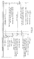
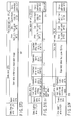
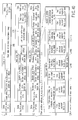
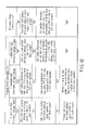
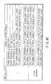
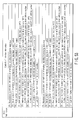
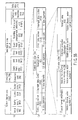
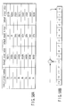
- FIG. 1 shows a combination, which produces a new technical feature and advantageous effect in the present embodiment. That is the information storage medium in the present embodiment has the following constituent elements:
- constituent elements correspond to the contents described in each column of FIG. 1.
- a technical feature and a unique advantageous effect of the present embodiment occur in combination of the specific embodiments of the constituent elements shown in FIG. 1.
- a description will be given with respect to a combination state of individual embodiments at a stage of explaining the embodiments.
- constituent elements which do not specify a combination, it denotes that the following characteristics are employed:
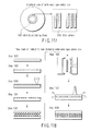
- FIG. 2A shows a standard phase change recording film structure (mainly used for a rewritable-type information storage medium), and FIG. 2B shows a standard organic dye recording film structure (mainly used for a write-once type information storage medium).
- a whole recording film structure excluding transparent substrates 2-1 and 2-2 shown in FIGS. 2A and 2B (including light reflection layers 4-1 and 4-2) is defined as a "recording film", and is discriminated from recording layers 3-1 and 3-2 in which a recording material is disposed.
- a material for the transparent substrates 2-1 and 2-2 there is employed a polycarbonate PC or an acrylic PMMA (poly methyl methacrylate) which is a transparent plastic material.
- a center wavelength of a laser light beam 7 used in the present embodiment is 405 nm, and refractive index n 21 , n 22 of the polycarbonate PC at this wavelength is close to 1.62.
- Standard refractive index n 31 and absorption coefficient k 31 in 405 nm at GeSbTe (germanium antimony tellurium) which is most generally used as a phase change type recording material are n 31 ⁇ 1.5 and k 31 ⁇ 2.5 in a crystalline area, whereas they are n 31 ⁇ 2.5 and k 31 ⁇ 1.8 in an amorphous area.
- a refractive index (in the amorphous area) of a phase change type recording medium is different from a refractive index of the transparent substrate 2-1, and reflection of a laser light beam 7 on an interface between the layers is easily occurred in a phase change recording film structure.
- a phase change recording film structure takes an enhancement structure; and (2) a refractive index difference between the layers is great or the like, a light reflection amount change at the time of reproduction from a recording mark recorded in a phase change recording film (a differential value of a light reflection amount from a recording mark and a light reflection amount from an unrecorded area) can be obtained as an interference result of multiple reflection light beams generated on an interface between the undercoat intermediate layer 5, the recording layer 3-1, the upper intermediate layer 6, and the light reflection layer 4-2.
- a light reflection amount change at the time of reproduction from a recording mark recorded in a phase change recording film a differential value of a light reflection amount from a recording mark and a light reflection amount from an unrecorded area
- an organic dye recording film structure takes a very simple laminate structure made of an organic dye recording layer 3-2 and a light reflection layer 4-2.
- An information storage medium (optical disk) using this organic dye recording film is called a write-once type information storage medium, which enables only one time of recording.
- this medium unlike a rewritable-type information storage medium using the phase change recording medium, this medium cannot carry out an erasing process or a rewriting process of information which has been recorded once.
- an optical reproduction principle of an organic color recording film (reason why a reflection light amount change occurs) is not “multiple interference” in a phase change recording film, and a main factor is a "light amount loss (including interference) midway of an optical path with respect to the laser light beam 7 which comes back after being reflected in the light reflection layer 4-2".
- a light amount loss midway of an optical path include an "interference phenomenon due to a phase difference partially caused in the laser light 7" or an "optical absorption phenomenon in the recording layer 3-2".
- the light reflection factor of the organic dye recording film in an unrecorded area on a mirror surface on which a pre-groove or a pre-pit does not exist is featured to be simply obtained by a value obtained by subtracting an optical absorption amount when the recording layer 3-2 is passed from the light reflection factor of the laser light beam 7 in the light reflection layer 4-2.
- this film is different from a phase change recording film whose light reflection factor is obtained by calculation of "multiple interference".
- the transparent substrate 2-2 is locally plastically deformed, there changes an optical distance of the laser light beam 7 reflected in the light reflection layer 4-2 through the transparent substrate 2-2, the laser light beam 7 coming back through the transparent substrate 2-2 again.
- a phase difference occurs between the laser light beam 7 from a recording mark, the laser light beam coming back through a portion of the locally plastically deformed transparent substrate 2-2, and a laser light beam 7 from the periphery of the recording mark, the laser light beam coming back through a portion of a transparent substrate 2-2 which is not deformed, and thus, a light amount change of reflection light beam occurs due to interference between these light beams.
- a change of a substantial refractive index n 32 produced by cavitation of the inside of the recording mark in the recording layer 3-2 due to gasification (evaporation), or alternatively, a change of a refractive index n 32 produced due to thermal decomposition of an organic dye recording material in the recording mark also contributes to the above described occurrence of a phase difference.
- the recording layer 3-2 can absorb energy of the laser light beam 7 at a first stage.
- the light absorption spectra in the recording layer 3-2 influence the recording sensitivity of an organic dye recording film.
- a principle of light absorption in an organic dye recording material which forms the recording layer 3-2 will be described with reference to (A3) of the present embodiment.
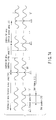
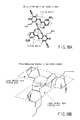
- FIG. 3 shows a specific structural formula of the specific contents "(A3) azo metal complex + Cu" of the constituent elements of the information storage medium shown in FIG. 1.
- a circular periphery area around a center metal M of the azo metal complex shown in FIG. 3 is obtained as a light emitting area 8.
- a laser light beam 7 passes through this light emitting area 8
- local electrons in this light emitting area 8 resonate to an electric field change of the laser light beam 7, and absorbs energy of the laser light beam 7.
- a value converted to a wavelength of the laser light beam with respect to a frequency of an electric field change at which these local electrons resonate most and easily absorbs the energy is called a maximum absorption wavelength, and is represented by ⁇ max .
- the light absorption spectra of the organic dye recording material in the case where there exists only one light emitting area 8 which is absolute 0 degree at a temperature and high in purity draws narrow linear spectra in close to a maximum absorption wavelength ⁇ max
- the light absorption spectra of a general organic recording material including impurities at a normal temperature, and further, including a plurality of light absorption areas exhibit a wide light absorption characteristic with respect to a wavelength of a light beam around the maximum absorption wavelength ⁇ max .
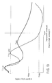
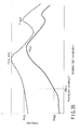
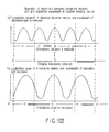
- FIG. 4 shows an example of light absorption spectra of an organic dye recording material used for a current DVD-R disk.
- a wavelength of a light beam to be irradiated with respect to an organic dye recording film formed by coating an organic dye recording material is taken on a horizontal axis, and absorbance obtained when an organic dye recording film is irradiated with a light beam having a respective wavelength is taken on a vertical axis.
- the absorbance used here is a value obtained by entering a laser light beam having incident intensity Io from the side of the transparent substrate 2-2 with respect to a state in which a write-once type information storage medium has been completed (or alternatively, a state in which the recording layer 3-2 has been merely formed on the transparent substrate 2-2 (a state that precedes forming of the optical reflection layer 4-2 with respect to a structure of FIG. 2B)), and then, measuring reflected laser light intensity Ir (light intensity It of the laser light beam transmitted from the side of the recording layer 3-2).
- the absorbance Ar (At) is represented by:
- absorbance Ar of a reflection shape expressed by formula (A-1) it is possible to define absorbance At of a transmission shape expressed by formula (A-2) without being limited thereto in the present embodiment.
- absorbance At of a transmission shape expressed by formula (A-2) there exist a plurality of light absorption areas, each of which includes the light emitting area 8, and thus, there exist a plurality of positions at which the absorbance becomes maximal.
- ⁇ max there exist a plurality of maximum absorption wavelength ⁇ max when the absorbance takes a maximum value.
- a wavelength of the recording laser light in the current DVD-R disk is set to 650 nm.
- a value of the maximum absorption wavelength ⁇ max which is the closest to the wavelength of the recording laser light beam becomes important. Therefore, only in the description of the present embodiment, the value of the maximum absorption wavelength ⁇ max set at a position which is the closest to the wavelength of the recording laser light beam is defined as " ⁇ max write"; and is discriminated from another ⁇ max ( ⁇ max 0).
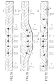
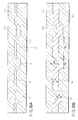
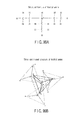
- FIGS. 5A and 5B each show a comparison in shape when a recording film is formed in a pre-pit area or a pre-groove area 10.
- FIG. 5A shows a shape relevant to a phase change recording film.
- any of methods of sputtering vapor deposition, vacuum vapor deposition, or ion plating is used in vacuum.
- irregularities of the transparent substrate 2-1 are duplicated comparatively faithfully.
- the sectional shape of the recording layer 3-1 and the light reflection layer 4-1 each is also rectangular or trapezoidal.
- FIG. 5B shows a general recording film sectional shape of a current DVD-R disk which is a conventional technique as a recording film in the case where an organic dye recording film has been used.
- a method for forming the recording film 3-2 there is used a method called spin coating (or spinner coating) which is completely different from that shown in FIG. 5A.
- the spin coating used here denotes a method for dissolving in an organic solvent an organic dye recording material which forms the recording layer 3-2; applying a coating onto the transparent substrate 2-2; followed by rotating the transparent substrate 2-2 at a high speed to spread a coating agent to the outer periphery side of the transparent substrate 2-2 by a centrifugal force; and gasifying the organic solvent, thereby forming the recording layer 3-2.
- the sectional shape on the interface between the light reflection layer 2-2 and the recording layer 3-2 is obtained as a shape which is different from the shape of the surface of the transparent substrate 2-2 (an interface between the transparent substrate 2-2 and the recording layer 3-2).
- the sectional shape on the interface between the light reflection layer 2-2 and the recording layer 3-2 is formed in a substantially V-shaped groove shape.
- the above sectional shape is formed in a substantially conical side surface shape. Further, at the time of spin coating, an organic solvent is easily collected at a recessed portion, and thus, the thickness Dg of the recording layer 3-2 in the pre-pit area or pre-groove area 10 (i.e., a distance from a bottom surface of the pre-pit area or pre-groove area to a position at which an interface relevant to the light reflection layer 2-2 becomes the lowest) is larger than the thickness D1 in a land area 12 (Dg > D1). As a result, an amount of irregularities on an interface between the transparent substrate 2-2 and the recording area 3-2 in the pre-pit area or pre-groove area 10 becomes substantially smaller than an amount of irregularities on the transparent substrate 2-2 and the recording layer 3-2.
- FIGS. 6A and 6B each show a plastic deformation state of a specific transparent substrate 2-2 at a position of a recording mark 9 in a write-once type information storage medium using a conventional organic dye material.
- a depth of a bottom surface 14 of a pre-groove area at the position of the recording mark 9 is different from a depth of a bottom surface of a pre-groove area 11 in an unrecorded area (in the example shown in FIG. 6A, the depth of the bottom surface 14 in the pre-groove area at the position of the recording mark 9 is shallower than that in the unrecorded area); and a case in which, as shown in FIG. 6B, a bottom surface 14 in a pre-groove area at the position of the recording mark 9 is distorted and is slightly curved (the flatness of the bottom surface 14 is distorted: In the example shown in FIG.
- the bottom surface 14 in the pre-groove area at the position of the recording mark 9 is slightly curved toward the lower side).
- a plastic deformation range of the transparent substrate 2-2 at the position of the recording mark 9 covers a wide range.
- a track pitch is 0.74 ⁇ m
- a channel bit length is 0.133 ⁇ m.
- the plastic deformation range of the transparent substrate 2-2 at the position of the recording mark 9 covers a wide range, and thus, the adjacent tracks are adversely affected, and the recording mark 9 of the existing adjacent track is substantially erased (cannot be reproduced) due to a "cross-write" or overwrite in which the recording mark 9 widens to the adjacent tracks.
- the channel bit length is narrower than 0.133 ⁇ m, there occurs a problem that inter-code interference appears; an error rate at the time of reproduction significantly increases; and the reliability of reproduction is lowered.
- a range of the thickness Dg of a recording layer 3-2 which can be substantially thermally analyzed becomes important.
- a conventional write-once type information storage medium CD-R or DVD-R
- the largest factor is "an interference effect due to a difference in optical distance in the recording mark 9 and in unrecorded area”.
- a difference in its optical difference is mainly caused by "a change of the thickness Dg of a physical recording layer 3-2 due to plastic deformation of the transparent substrate 2-2 (a physical distance from an interface between the transparent substrate 2-2 and the recording layer 3-2 to an interface between the recording layer 3-2 and a light reflection layer 4-2) and "a change of refractive index n 32 of the recording layer 3-2 in the recording mark 9". Therefore, in order to obtain a sufficient reproduction signal (change of light reflection amount) between the recording mark 9 and the unrecorded area, when a wavelength in vacuum of laser light beam is defined as ⁇ , it is necessary for the value of the thickness 3-2 in the unrecorded area has a size to some extent as compared with ⁇ /n 32 .
- the range of the thickness Dg can be specified.
- a step amount between a pre-pit area and a land area is ⁇ /(8n 21 ) when the largest track shift detection signal is obtained by using a push-pull technique.
- an organic dye recording film shown in FIG. 5B as described previously, the shape on an interface between the recording layer 3-2 and the light reflection layer 4-2 becomes blunt, and a step amount becomes small.
- the refractive index at 405 nm in the case where polycarbonate has been used as a material for the transparent substrate 2-2 is n 22 ⁇ 1.62, and thus, it is necessary to increase a step amount between the pre-pit area and the land area more significantly than 31 nm.
- the thickness Dg of the recording layer 3-2 in the pre-groove area is greater than a step amount between the pre-pit area and the land area on the transparent substrate 2-2, there is a danger that thickness D1 of the recording layer 3-2 in a land area 12 is eliminated. Therefore, from the above described discussion result, it is necessary to meet a condition that: D g ⁇ 31 nm
- condition for formula (4) is also a condition, which should be met in the present embodiment in which plastic deformation of the transparent substrate 2-2 does not occur.
- a boundary position of a substrate deformation area blurs (is ambiguous), and thus, a window margin is lowered more significantly.
- a sectional shape of an area in which the recording mark 9 is formed is observed by an electron microscope, it is believed that a blurring amount of the boundary position of the substrate deformation area increases as the value of the thickness Dg of the recording layer 3-2 increases.
- the lower limit value of the channel bit length allowed for allocation of a sufficient window margin is in order of two times of the thickness Dg of the recording layer 3-2, and it is desirable that the lower limit value is greater than 120 nm.
- the gasification (evaporation) temperature of the organic dye recording material is different depending on the type of the organic dye material, in general, the temperature ranges 220°C to 370°C, and a thermal decomposition temperature is lower than this range.
- a glass transition temperature 150°C of a polycarbonate resin has been presumed as an arrival temperature at the time of substrate deformation in the above discussion, a temperature difference between 150°C and 220°C is small, and, when the transparent substrate 2-2 reaches 150°C, the inside of the recording layer 3-2 exceeds 220°C.
- the value of the refractive index n 32 or absorption coefficient k 32 changes in a comparatively wide range in the recording layer 3-2 at the periphery of a recording mark 9, which is thermal deformed at the side of the transparent substrate 2-2, and this change seems to cause "cross-write” or "cross-erase” for the adjacent tracks. It is possible to set a lower limit value of track pitch in which "cross-write” or “cross-erase” does not occur with the width of an area which reaches a temperature which changes the refractive index n 32 or absorption coefficient k 32 in the recording layer 3-2 when the transparent substrate 2-2 exceeds a thermal deformation temperature.
- the present embodiment is primarily featured in "inventive organic dye material” in which "a local optical characteristic change in the recording layer 3-2, which occurs at a comparatively low temperature, is a principle of recording” and “setting environment (recording film structure or shape) in which the above principle of recording easily occurs without causing a substrate deformation and gasification (evaporation) in the recording layer 3-2.
- Specific characteristics of the present embodiment can be listed below.
- the light emitting area 8 is partially destroyed or the size of the light emitting area 8 changes, whereby a substantial light absorption sectional area changes. In this manner, an amplitude (absorbance) at a position of ⁇ max write changes in the recording mark 9 while a profile (characteristics) of light absorption spectra (FIG. 4) itself is maintained.
- Electron structure in a light emitting area is stabilized, and structural decomposition relevant to ultraviolet ray or reproduction light irradiation is hardly generated
- a passage speed (line speed) of a focusing spot of light passing through the recording layer 3-2 is set to 6.61 m/s
- the line speed in the B format is set in the range of 5.0 m/s to 10.2 m/s.
- the line speed at the time of reproduction in the present embodiment is equal to or greater than 5 m/s.
- a start position of a data lead-in area DTLDI in the H format is 47.6 mm in diameter.
- user data is recorded in location equal to or greater than 45 mm in diameter.
- An inner periphery of 45 mm in diameter is 0.141 m, and thus, the rotation frequency of an information storage medium when this position is reproduced at a line speed of 5 m/s is obtained as 35.4 rotations/s.
- Video image information such as TV program is provided as one of the methods utilizing a write-once type information storing medium according to the present embodiment.
- pause temporary stop
- a reproduction focusing spot stays on a track of its paused position.
- the spot stops on the track of the paused position, the user can start reproduction at the paused position immediately after a "reproduction start button” has been pressed.
- a "pause (temporary stop) button in the case where a customer visits the user's home immediately after the user has gone to toilet, there is a case in which the pause button is left to have been pressed for one hour while the user meets the customer.
- the write-once type information storage medium makes 35.4 ⁇ 60 ⁇ 60 ⁇ 130,000 rotations for one hour, and the focusing spot traces on the same track during this period (130,000 repetitive playbacks). If the recording layer 3-2 is degraded due to repetitive playback and video image information cannot be reproduced after this period, the user coming back one hour later cannot see any portion of video image, and thus, gets angry, and in the worst case, there is a danger that the problem may be taken to court. Therefore, a minimum condition that, if the recorded video image information is not destroyed even if such a pausing is left for one hour or longer (even if continuous playback in the same track occurs), no video image data is destroyed, requires to guarantee that at least 100,000 repetitive playback occurs, no reproduction degradation occurs.
- the write-once type information storage medium desirably makes 1,000,000 repetitive playbacks, no problem occurs with use by the general user, and it is considered sufficient to set to about 1,000,000 times the upper limit value of the repetitive playback count as long as the recording layer 3-2 is not degraded. If the upper limit value of the repetitive playback count is set to a value which significantly exceeds 1,000,000 times, there occurs inconvenience that "recording sensitivity is lowered" or "medium price increases".
- recording power is defined in a range set in formulas (8) to (13). It is said that a semiconductor laser beam is featured in that continuous light irradiation is not stable in a value equal to or smaller than 1/80 of the maximum use power. Because the power, which is 1/80 of the maximum use power, is in location in which light irradiation is just started (mode initiation is started), mode hopping is likely to occur.
- the values of the reproduction power is set below around the value which is 1/80 of the value described at the right side of formula (12) or formula (13): Optical reproduction power > 0.19 ⁇ 0.65 / NA 2 ⁇ V / 6.6 Optical reproduction power > 0.19 ⁇ 0.65 / NA 2 ⁇ V / 6.6 1.2
- the value of the optimal reproduction power is restricted by a dynamic range of a power monitoring optical detector.
- a recording/reproducing optical head incorporates an optical detector which monitors a light emission amount of a semiconductor laser light source.
- this optical detector detects a light emission amount and applies a feedback to an amount of a current to be supplied to the semiconductor laser light source at the time of light irradiation.
- a commercially available, inexpensive optical detector is often molded with a resin (an optical detecting unit is surrounded).
- 530 nm or less (in particular, 455 nm or less) is used as a light source wavelength in the present embodiment.
- a resin with which the optical detecting unit is molded mainly, epoxy resin
- a mold resin degradation is likely to occur because the storage medium has a pre-groove area 11 as shown in FIGS.
- This mold resin characteristic degradation mainly occurs due to a photon mode (optical action), and however, it is possible to predict an upper limit value of an allowable irradiation amount in comparison with a light emission amount in a thermal mode (thermal excitation). Assuming the worst case, let us assume an optical system in which an optical detector is arranged at an image forming position as an optical head.
- the optical density of the detected light focused on the optical detector is obtained as 1/M 2 of the optical density of convergence light irradiated on the recording layer 3-2, and thus, a temperature rise amount on the optical detector at the time of reproduction is obtained as ⁇ T read /M 2 which is a rough estimate.
- ⁇ T read /M 2 which is a rough estimate.
- the image foaming magnification of the detecting system in the optical head M is in order of 3 times to 10 times in general, if the magnification M 2 ⁇ 10 is tentatively estimated, it is necessary to set reproduction power so as to obtain: ⁇ T read / ⁇ T write ⁇ 20
- optimal reproduction power is assigned as follows: Optimal reproduction power ⁇ 3 ⁇ 0.65 / NA 2 ⁇ V / 6.6 Optimal reproduction power ⁇ 3 ⁇ 0.65 / NA 2 ⁇ V / 6.6 1 / 2 Optimal reproduction power ⁇ 2 ⁇ 0.65 / NA 2 ⁇ V / 6.6 Optimal reproduction power ⁇ 2 ⁇ 0.65 / NA 2 ⁇ V / 6.6 1 / 2 Optimal reproduction power ⁇ 1.5 ⁇ 0.65 / NA 2 ⁇ V / 6.6 Optimal reproduction power ⁇ 1.5 ⁇ 0.65 / NA 2 ⁇ V / 6.6 1 / 2
- the optical detector is fixed as compared with the fact the information storage medium rotates and relatively moves, and thus, in consideration of this fact, it is necessary to further set the optimal reproduction power to be in order of 1/3 or less of the value obtained in the above formula.
- a value of the reproduction power is set to 0.4 mW.
- the present embodiment is featured in that a technical contrivance is carried out in recording film structure or shape such as:
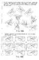
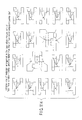
- FIGS. 7A, 7B and 7C the open (blank) arrow indicates an optical path of an irradiation laser light beam 7, and the arrow of the dashed line indicates a thermal flow.
- a recording film structure shown in FIG. 7A indicates an environment in which an optical characteristic change inside of a recording layer 3-2 corresponding to the present embodiment is most likely to occur. That is, in FIG. 7A, the recording layer 3-2 consisting of an organic dye recording material has uniform thickness anywhere in the range shown in formula (3) or formula (4) (where the thickness is sufficiently large), and receives irradiation of the laser light beam 7 in a direction vertical to the recording layer 3-2.
- a silver alloy is used as a material for a light reflection layer 4-2 in the present embodiment.
- a material including a metal with high light reflection factor in general, has high thermal conductivity and heat radiation characteristics without being limited to the silver alloy. Therefore, although a temperature of the recording layer 3-2 is risen by absorbing the energy of the irradiated laser light beam 7, a heat is radiated toward the light reflection layer 4-2 having heat radiation characteristics.
- a recording film shown in FIG. 7A is formed anywhere in a uniform shape, a comparatively uniform temperature rise occurs inside of the recording layer 3-2, and a temperature difference at points ⁇ , ⁇ , and ⁇ at the center part is comparatively small.
- a step is provided partly of the recording film 3-2.
- the radiation of the laser light beam 7 is subjected in a direction oblique to a direction in which the recording layer 3-2 is arrayed, and thus, an irradiation amount of the laser light beam 7 per a unit area is relatively lowered as compared with the point ⁇ of the center part.
- a temperature rise amount in the recording layer 3-2 at the points ⁇ and ⁇ is lowered.
- thermal radiation toward the light reflection layer 4-2 occurs, and thus, the arrival temperature at the points ⁇ and s is sufficiently lowered as compared with the point ⁇ of the center part.
- a temperature difference at the point ⁇ of the center part relevant to the points ⁇ and ⁇ is very large.
- a gasification (evaporation) temperature is exceeded at the point ⁇ of the center part or the surface of a transparent substrate (not shown) in the vicinity of the point ⁇ of the center part hardly exceeds a thermal deformation temperature.
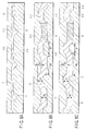
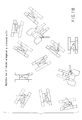
- FIGS. 8A, 8B and 8C a description will be given with respect to: the contents of a technical contrivance in the present embodiment relating to the pre-groove shape/dimensions for providing "setting of environment (structure or shape of a recording film)" in which a principle of recording according to the present embodiment is likely to occur; and the contents of a technical contrivance in the present embodiment relating to a thickness distribution of the recording layer.
- FIG. 8A shows a recording film structure in a conventional write-once type information storage medium such as CD-R or DVD-R; and FIGS. 8B and 8C each show a recording film structure in the present embodiment.
- a recording mark 9 is formed in a pre-groove area 11.
- FIG. 8A there have been many cases in which a pre-groove area 11 is formed in a "V-groove" shape in a conventional write-once type information storage medium such as CD-R or DVD-R.
- a planar shape orthogonal to a traveling direction of the incident laser light beam 7 is provided in the pre-groove area 11 at the side of at least the "transparent substrate 2-2".
- Wg:W1 6:4
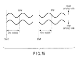
- a wall face of the pre-groove area 11 is concentrated (made close to the V-groove) in the vicinity of a center at which the intensity of a reproducing focusing spot is the highest and a wobble amplitude amount is increased, whereby the wobble signal detection precision has been guaranteed.
- FIGS. 8B and 8C after the flat area in the pre-groove area 11 in the present embodiment has been widened, when the oblique surface of the pre-groove area 11 is shifted to the outside relatively than a center position of the reproducing focusing spot, a wobble detection signal is hardly obtained.
- the present embodiment is featured in that the width Wg of the pre-groove area described above is widened and the H format utilizing PSK (Phase Shift Keying) in which slot gaps at wobble detection is always fixedly maintained or the B format utilizing FSK (Frequency Shift Keying) or STW (Saw Tooth Wobble) are combined, whereby stable recording characteristics are guaranteed (suitable to high speed recording or layering) at low recording power and stable wobble signal detection characteristics are guaranteed.
- PSK Phase Shift Keying
- FSK Frequency Shift Keying
- STW Scw Tooth Wobble
- the thickness in a portion at which the recording layer 3-2 in the land area 12 is the thickest is defined as recording layer thickness D1 in the land area 12; and a portion at which the recording layer 3-2 in the pre-groove area 11 is the thickest is defined as recording layer thickness Dg in the pre-groove area.
- the recording layer thickness D1 in the land area is relatively increased, whereby a local optical characteristic change in the recording layer is stably likely to occur at the time of recording.
- the present embodiment is featured by recording power control, as described in item [ ⁇ ].
- the formation of the recording mark 9 due to a local optical characteristic change in the recording layer 3-2 occurs at a temperature, which is much lower than a plastic deformation temperature of the conventional transparent substrate 2-2, at a thermal decomposition temperature in the recording layer 3-2, or a gasification (evaporation) temperature.
- an upper limit value of recording power is restricted so as not ensure that the transparent substrate 2-2 locally exceeds a plastic deformation temperature at the time of recording or a thermal decomposition temperature or a gasification (evaporation) temperature is locally exceeded in the recording layer 3-2.
- the "recording power” described above denotes a sum of exposure amount irradiated to the recording layer 3-2.
- the optical energy density at a center part of a focusing spot and at a portion at which the optical intensity density is the highest is obtained as parameters targeted for discussion in the present embodiment.
- optimal recording power changes depending on a line speed V in phase change type recording material.
- optimal recording power changes in proportion to a 1/2 square of a line speed V in phase change type recording material, and changes in proportion to a line speed V in organic dye recording material. Therefore, a conversion formula of optimal recording power considering a line speed V, obtained by extending formula (5), is obtained as follows:
- a condition for formula (8) or formula (9) is obtained as a mandatory condition; a target condition for formula (10) or formula (11) is obtained; and a condition for formula (12) or formula (13) is obtained as a desirable condition.
- a recording film having characteristics that a light reflection amount in a recording mark 9 is lower than that in an unrecorded area is referred to as an "H-L” recording film.
- a recording film in which the above light reflection amount is high is referred to as an "L-H” recording film.
- the present embodiment is featured in that:
- a wavelength of ⁇ max write is shorter than a use wavelength utilized for recording/reproduction (in the vicinity of 405 nm).
- a change of absorbance is small between an unrecorded portion and a recorded portion. If a change of absorbance is small between the unrecorded portion and the recorded portion, a large reproduction signal amplitude cannot be obtained.
- a design of the recording film 3-2 is made so that a wavelength of ⁇ max write arrives at the outside ranging from 355 nm to 455 nm, i.e., arrives at the shorter wavelength side than 355 nm.
- the light reflection factor from a recording film in an unrecorded state coincides with that at 405 nm in the light reflection layer 4-2.
- a light reflection factor of the light reflection layer 4-2 will be described later in detail in the section "6-1) Light reflection layer".
- the light reflection factor of the light reflection layer 4-2 is defined as 100% for the sake of simplification.
- the light reflection factor can be set to 40% or more.
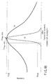
- an organic dye recording material which meets formula (14) in an unrecorded location, is selected.
- the above formula (14) assumes that, in FIG. 9, the light reflection factor is obtained as 0% when the light reflection layer 4-2 is reflected over the recording layer 3-2 with a light beam having a wavelength of ⁇ max write ⁇
- the light reflection factor is not obtained as 0%, and has a certain degree of light reflection factor.
- the light absorption spectrum profile in the recording mark changes comparatively broadly, and there is a possibility that a molecular structure change in molecules occurs and partial precipitation (coal tar) of carbon atoms occurs.
- the present embodiment is featured in that a value of a wavelength ⁇ 1 max at which the absorbance in the recording mark becomes maximal is made closer to a reproduction wavelength of 405 nm than a value of a wavelength ⁇ max write at an unrecorded position, thereby generating a reproduction signal in the "H-L" recording film.
- the absorbance at the wavelength ⁇ 1 max at which the absorbance is the highest becomes smaller than "1"
- a value of the absorbance Al 405 at a reproduction wavelength of 405 nm becomes greater than a value of Ah 405 .
- a total light reflection factor in a recording mark is lowered.
- ETM Eight to Twelve: 8-bit data code is converted to 12-channel bit
- RLL (1, 10)
- a minimum inversion length relevant to a 12-channel bit length T is 2T, and a maximum inversion length is 11T.
- a PRML method is utilized at the time of signal reproduction recorded at high density, and a signal processor circuit and a state transition chart shown in FIGS. 15 to 17 is used (A detailed description is given later).
- the linearity of a reproduction signal is requested.
- the characteristic of the signal processor circuit shown in FIGS. 15 and 16 has been analyzed based on the state transition chart shown in FIG. 17, in order to ensure the linearity of the above reproduction signal.
- I 3 a ratio relevant to the above I 11 of a value when a recording mark having a length of 3T and a reproduction signal amplitude from a repetition signal of an unrecorded space is defined as I 3 meets: I 3 / I 11 ⁇ 0.35 or desirably, I 3 / I 11 > 0.2
- Formula (25) is a formula derived from a very coarse result of discussion, and is merely shown as a basic concept. Because the Ah 405 setting range is specified in accordance with formula (16), in the present embodiment, at least a condition for Al 405 is mandatory as: A l 405 > 0.3
- a wavelength of ⁇ max write is shorter than a wavelength of reproduction light or recording/reproducing light (for example, 405 nm)
- the wavelength of ⁇ max write may be longer than a wavelength of reproduction light or recording/reproducing light (for example, 405 nm), without being limited thereto.
- the thickness Dg of the recording layer 3-2 is influenced. For example, if the thickness Dg of the recording layer 3-2 significantly exceeds an allowable value, optical characteristics of only a part coming into contact with the transparent substrate 2-2 in the recording layer 3-2 are changed as a state that follows forming of the recording mark 9, whereby the optical characteristics of a portion coming into contact with the light reflection layer 4-2 adjacent to its location are obtained as a value equal to that in the unrecorded area. As a result, a reproduction light amount change is lowered, and a value of I 3 in formula (22) or formula (23) is reduced, and a condition for formula (22) or formula (23) cannot be met.
- the thickness Dg of the recording layer 3-2 is set to "3T” or less based on the discussion of thermal analysis; and a condition meeting formula (23) is such that the thickness Dg of the recording layer 3-2 is set to "3 x 3T" or less.
- the thickness may be set to "T” or less in consideration of effect of a tilt due to a facial motion or warping of the write-once type information storage medium or a margin relevant to a focal blurring.
- the thickness Dg of the recording layer 3-2 in the present embodiment is set in the range assigned in a required minimum condition that: 9 T ⁇ D g ⁇ ⁇ / 8 n 32 and in a desired condition that: 3 T ⁇ D g ⁇ ⁇ / 4 n 32
- the severest condition can be defined as: T ⁇ D g ⁇ ⁇ / 4 n 32
- a value of the channel bit length T is 102 nm in the H format, and is 69 nm to 80 nm in the B format.
- a value of 3T is 306 nm in the H format and is 207 nm to 240 nm in the B format.
- a value of 9T is 918 nm in the H format and is 621 nm to 720 nm in the B format.
- An optical head (not shown) is arranged in an information recording/reproducing unit 141 shown in FIG. 11.
- a wavelength of a light source (semiconductor laser) used in the optical head is 405 nm
- the present embodiment is not limited thereto, and there can be used a light source having a use wavelength equal to or shorter than 620 nm or 530 nm or a light source ranging from 355 nm to 455 nm, as described previously.
- two objective lenses used to focus the light beam having the above wavelength onto the information storage medium may be incorporated in the optical head.
- an objective lens having a NA value of 0.65 In the case where a recording/reproducing operation is carried out with respect to an information storage medium in the H format, an objective lens having a NA value of 0.65 is used.
- As an intensity distribution of incident light immediately before the light is incident to an objective lens, the relative intensity at the periphery of the objective lens (at the boundary position of an aperture) when the center intensity is set to "1" is referred to as "RIM Intensity".
- a value of the RIM intensity in the H format is set in the range of 55% to 70%.
- a wave surface aberration amount in the optical head is optically designed so as to be 0.33 ⁇ (0.33 ⁇ or less) with respect to a use wavelength ⁇ .
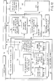
- a partial response maximum likelihood is used for information reproduction to achieve high density of an information storage medium (FIG. 1, point [A]).
- PRML partial response maximum likelihood
- line density can be increased and the reliability of a reproduction signal can be improved (i.e., demodulation reliability can be improved) when a servo correction error such as a focal blurring or a track shift has occurred.
- PR(1, 2, 2, 2, 1) is employed (FIG. 1, point [A1]).
- a channel bit pattern after modulated is recorded in an information storage medium in accordance with a (d, k; m, n) modulation rule (In the above described method, this denotes RLL(d, k) of m/n modulation).
- RLL Error to Twelve Modulation
- ETM Eight to Twelve Modulation
- d 8-bit data
- a channel bit gap is reduced to the minimum.
- the data is close to a shutdown frequency having MTF characteristics of a reproducing optical system, and thus, a signal amplitude of a reproduced raw signal is formed in a shape almost hidden by noise.
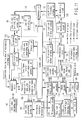
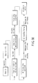
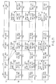
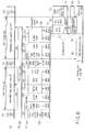
- a partial response maximum likelihood (PRML) technique is used as a method for thus reproducing a recording mark or a pit, which has been dense up to the vicinity of a limit of the MTF characteristics (shutdown frequency). That is, a signal reproduced from the information recording/reproducing unit 141 receives reproducing waveform correction by a PR equalizer circuit 130.
- a signal having passed through the PR equalizer circuit 130 is sampled by converting a signal after passing through the PR equalizer circuit 130 to a digital amount in accordance with a timing of a reference clock 198 sent from a reference clock generating circuit 160; the sampled signal is converted to a digital data by an AD converter 169; and a Viterbi decoding process is carried out in a Viterbi decoder 156.
- the data after Viterbi-decoded is processed as data, which is completely similar to binary data at a conventional slice level.
- the information reproducing apparatus or information recording/reproducing apparatus has another sampling timing sampling circuit in particular (combination of Schmidt trigger binarizing circuit 155 and PLL circuit 174).
- This Schmidt trigger circuit 155 has a specific value (forward direction voltage value of diode in actuality) at a slice reference level for binarizing, and is featured in that binarizing is provide only when the specific width has been exceeded.
- a PLL circuit 174 detects a shift in frequency and phase between a binary signal which is an output of this Schmidt trigger binarizing circuit 155 and a signal of a reference clock 198 sent from a reference clock generating circuit 160 to change the frequency and phase of the output clock of the PLL circuit 174.
- a reference clock generating circuit 160 applies a feedback to (a frequency and a phase) of a reference clock 198 so as to lower an error rate after Viterbi decoded, by using an output signal of this PLL circuit 174 and decoding characteristic information on a Viterbi decoder 156 and a convergence length (information on (distance to convergence)) in a path metric memory in the Viterbi decoder 156, although is not specifically shown).
- the reference clock 198 generated by this reference clock generating circuit 160 is utilized as a reference timing at the time of reproduction signal processing.
- a sync code position sampling unit 145 serves to detect the presence and position of a sync code, which coexists in an output data train of the Viterbi decoder 156 and to sample a start position of the above output data. While this start position is defined as a reference, a demodulator circuit 152 carries out a demodulating process with respect to data temporarily stored in a shift resistor circuit 170. In the present embodiment, the above temporarily stored data is returned to its original bit pattern with reference to a conversion table recorded in a demodulating conversion table recording unit 154 on 12-channel bit by bit basis. Then, an error correcting process is performed by an ECC decoding circuit 162, and descrambling is carried out by a descrambling circuit 159.
- Address information is recorded in advance by wobble modulation in a recording type (rewritable type or write-once type) information storage medium according to the present embodiment.
- a wobble signal detecting unit 135 reproduces this address information (i.e., judges the contents of a wobble signal), and supplies information required to provide an access to a desired location to the control unit 143.
- a sync code is added by a sync code generating/adding unit 146, and data is recorded in an information storage medium in the information recording/reproducing unit 141.
- DSV values after modulated are sequentially calculated by a DSV (Digital Sum Value) calculating unit 148, and the serially calculated values are fed back to code conversion after modulated.
- the high density of the information storage medium is achieved (in particular, line density is improved) by using the PRML system for reproduction in a data area, a data lead-in area, and a data lead-out area.
- compatibility with a current DVD is ensured and reproduction stability is ensured by using a slice level detecting system for reproducing in a system lead-in area and a system lead-out area.
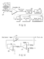
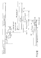
- FIG. 13 shows an embodiment of a signal reproducing circuit using a slice level detecting system used at the time of reproduction in a system lead-in area and a system lead-out area.
- a quadrature optical detector 302 in FIG. 13 is fixed into the optical head, which exists in the information recording/reproducing unit 141 in FIG. 11.
- a signal having taken a sum of detection signals obtained from optical detecting cells 1a, 1b, 1c, and 1d of the quadrature optical detector 302 is referred to as a "lead channel 1 signal".
- From a preamplifier 304 to a slicer 310 in FIG. 13 corresponds to a detailed structure in the slice level detecting circuit 132 in FIG. 11.
- a reproduction signal obtained from an information storage medium is subjected to a waveform equalizing process by a pre-equalizer 308 after the signal has passed through a high path filter 306 which shuts out a frequency component lower than a reproduction signal frequency bandwidth.
- this pre-equalizer 308 minimizes a circuit scale by using a 7-tap equalizer and can detect a reproduction signal precisely.
- the 7-tap equalizer is used.
- a VFO circuit/PLL 312 in FIG. 13 corresponds to the PLL circuit 174 in FIG. 11; and a demodulating/ECC decoding circuit 314 in FIG. 13 corresponding to the decoding circuit 152 and the ECC decoding circuit 162 in FIG. 11.
- FIG. 14 shows a detailed structure in a circuit of the slicer 310 in FIG. 13.
- a binary signal after sliced is generated by using a comparator 316.
- a cutoff frequency of this low path filter is set to 5 KHz.
- the cutoff frequency is set to 5 KHz in consideration of a relationship between RLL(1, 10) and a reference frequency of a channel bit described previously.
- a PLL circuit 334 in FIG. 15 is a part in the PR equalizer circuit 130, and denotes an element other than the Schmidt trigger binarizing circuit 155.
- a primary cutoff frequency of a high path filter circuit 306 in FIG. 15 is set at 1 KHz.
- a pre-equalizer circuit 308 uses a 7-tap equalizer in the same manner as that in FIG. 13 (because the use of the 7-tap equalizer minimizes a circuit scale and can detect a reproduction signal precisely).
- a sample clock frequency of an A/D converter circuit 324 is set to 72 MHz, and a digital output is produced as an eight-bit output.
- a reproduction signal is affected by a level change (DC offset) of its entire signal, an error is likely to occur at the time of Viterbi demodulation.
- a structure of correcting an offset by the offset canceller 336 using a signal obtained from an equalizer output In the embodiment shown in FIG. 15, an adaptive equalizing process is carried out in the PR equalizer circuit 130.
- a tap controller for automatically correcting tap coefficients in the equalizer 330 is utilized by utilizing an output signal of the Viterbi decoder 156.
- FIG. 16 shows a structure in the Viterbi decoder 156 shown in FIG. 11 or 15.
- a branch metric relevant to all branches, which can be predicted in response to an input signal, is calculated by a branch metric calculating unit 340, and the calculated value is sent to an ACS 342.
- the ACS 342 is an acronym of Add Compare Select, which calculates a path metric obtained by adding branch metrics in response to each of the passes which can be predicted in the ACS 342 and transfers the calculation result to a path metric memory 350.
- a calculating process is carried out with reference to the information contained in the path metric memory 350.
- a path memory 346 temporarily stores a value of the path metric corresponding to each path (transition) state and such each path, which can be predicted in the memory 346, the value being calculated by the ACS 342.
- An output switch unit 348 compares a path metric corresponding to each path, and selects a path when a path metric value becomes minimal.
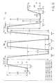
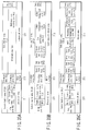
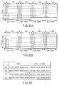
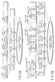
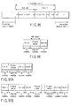
- the exposure levels at the time of recording have four levels of recording power (peak power), bias power 1, bias power 2, and bias power 3.
- peak power When a long (4T or more) recording mark 9 is formed, modulation is carried out in the form of multi-pulses between recording power (peak power) and bias power 3.
- a minimum mark length relevant to a channel bit length T is obtained as 2T.
- one write pulse of recording power (peak power) after bias power 1 is used as shown in FIG. 18, and bias power 2 is temporarily obtained immediately after the write pulse.
- bias power 2 is temporarily used after exposing two write pulses, a first pulse and a last pulse of recording power (peak power) level that follows bias power 1.
- bias power 2 is used after multi-pulse and write pulse exposure.
- the vertical dashed line in FIG. 18 shows a channel clock cycle.
- the laser power is risen at a position delayed by T SFP from a clock edge, and fallen at a position, which is backward by T ELP from an edge of a succeeding clock.
- a cycle during which the laser power is set at bias power 2 is defined as T LC - Values of T SFP , T ELP , and T LC are recorded in physical format information PFI contained in a control data zone CDZ as described later in the case of the H format.
- the laser power is risen at a position delayed by T SFP from a clock edge, and lastly, ended with a last pulse.
- Each of intervals T ELP - T SFP , T MP , T ELP - T SLP , and T LC is defined as a half-value wide relevant to a maximum value, as shown in FIG. 19.
- the above parameter setting range is defined as follows: 0.25 T ⁇ T S F P ⁇ 1.50 T 0.00 T ⁇ T E L P ⁇ 1.00 T 1.00 T ⁇ T E F P ⁇ 1.75 T ⁇ 0.10 T ⁇ T S L P ⁇ 1.00 T 0.00 T ⁇ T L C ⁇ 1.00 T 0.15 T ⁇ T M P ⁇ 0.75 T
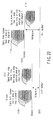
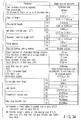
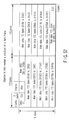
- FIGS. 21A, 21B and 21C each shows parameter values when optimal recording power of the write-once type information storage medium recorded in a principle of recording shown in the present embodiment has been checked, as described in the section "3-3) Recording characteristics common to organic dye recording film in the present embodiment".
- the values of bias power 1, bias power 2, and bias power 3 are 2.6 mW, 1.7 mW, and 1.7 mW, and reproduction power is 0.4 mW.
- a signal appears in an opposite direction in an emboss area (such as system lead-in area SYSDI) and a recording mark area (data lead-in area DTLDI, data lead-out area DTLDO, or data area DTA).
- SYSDI system lead-in area
- DTLDI data lead-in area
- DTLDO data lead-out area
- DTA data area
- the reproduction signal characteristics obtained from a recording mark recorded on the "L-H” recording film shown in the present embodiment is adjusted to conform to signal characteristics obtained from the "H-L” recording film to meet formulas (20) to (23).
- the same signal processor circuit can be used, and the signal processor circuit can be simplified and reduced in price.
- the relative absorbance in an unrecorded area is basically low in the "H-L” recording film, and thus, when reproduction light has been irradiated at the time of reproduction, there occurs an optical characteristic change generated by absorbing energy of the reproduction light. Even if an optical characteristic change (update of recording action) has occurred after the energy of the reproduction light has been absorbed in a recording mark having high absorbance, a light reflection factor from the recording mark is lowered. Thus, reproduction signal processing is less affected because such a change works in a direction in which an amplitude of a reproduction signal (I 11 ⁇ I 11H - I 11L ) of the reproduction signal increases.
- the "L-H” recording film has optical characteristics that "a light reflection factor of an unrecorded portion is lower than that in a recording mark". This means that, as is evident from the contents described with respect to FIG. 2B, the absorbance of the unrecorded portion is higher than that in the recording mark.
- signal degradation at the time of reproduction is likely to occur as compared with the "H-L” recording film.
- Basic characteristics common to organic dye recording material in the invention there is a need for improving reliability of reproduction information in the case where reproduction signal degradation has occurred due to ultraviolet ray or reproduction light irradiation".
- the present embodiment is featured in that, in the "L-H" recording film, a value of ⁇ max write (maximum absorption wavelength which is the closest to wavelength of recording light) is longer than a wavelength of recording light or reproduction light (close to 405 nm).
- the absorbance relevant to the ultraviolet ray can be reduced, and the durability relevant to ultraviolet ray irradiation can be significantly improved.
- a difference in absorbance between a recorded portion and an unrecorded portion in the vicinity of ⁇ max write is small, and a degree of reproduction signal modulation (signal amplitude) in the case where the wavelength light in the vicinity of ⁇ max write is reduced.
- a sufficiently large degree of reproduction signal modulation (signal amplitude) be taken in the range of 355 nm to 455 nm.
- a design of a recording film 3-2 is made so that a wavelength of ⁇ max write exists out of the range of 355 nm to 455 nm (i.e., at a longer wavelength than 455 nm).
- FIG. 25 shows an example of light absorption spectra in the "L-H” recording film in the present embodiment.
- the light reflection factor of the whole recording film at a wavelength of ⁇ max write is designated by R ⁇ max write.
- formula (36) is derived. However, in actuality, the factor is not set to "0", and thus, it is necessary to drive a severer formula.
- a severe conditional formula for setting the upper light value ⁇ of the light reflection factor of the non-recording portion ' "L" portion) of the "L-H" recording film to 32% is given by: 1 ⁇ A l 405 ⁇ 1 ⁇ R ⁇ max write ⁇ 0.32
- a l 355 ⁇ 40 % A l 455 ⁇ 40 % it is possible to ensure stable recording characteristics or reproduction characteristics even if a wavelength of a light source is changed in the range of 355 nm to 405 nm or in the range of 405 nm to 455 nm (in the range of 355 nm to 455 nm in the case where both of the formulas are met at the same time).
- FIG. 26 shows a light absorption spectrum change after recorded in the "L-H" recording film according to the present embodiment. It is considered that a value of a maximum absorption wavelength ⁇ I max in a recording mark deviates from a wavelength of ⁇ max writes and an inter-molecular array change (for example, an array change between azo metal complexes) occurs. Further, it is considered that a discoloring action (cutting of local electron orbit (local molecular link dissociation)) occurs in parallel to a location in which both of the absorbance in location of ⁇ l max and the absorbance Al 405 at 405 nm are lowered and the light absorption spectra spreads itself.
- a discoloring action cutting of local electron orbit (local molecular link dissociation)
- the organic dye recording film 3-2 in the present embodiment is composed of a positively charged "cation portion" and a negatively charged "anion portion".
- the above recording film is technically featured in that: coupling stability is improved by utilizing a "dye” having chromogenic characteristics for the positively charged “cation portion” and utilizing an organic metal complex for the negatively charged “anion portion”; and there is met a condition that " ⁇ ] an electron structure in a chromogenic area is stabilized, and structural decomposition relevant to ultraviolet ray or reproduction light irradiation hardly occurs” shown in "3-2-B] Basic feature common to organic dye recording material in the present embodiment".
- an "azo metal complex” whose general structural formula is shown in FIG. 3 is utilized as an organic metal complex.
- cobalt or nickel is used as a center metal M of this azo metal complex, thereby enhancing optical stability.
- a center metal M of this azo metal complex there may be used: scandium, yttrium, titanium, zirconium, hafnium, vanadium, niobium, tantalum, chrome, molybdenum, tungsten, manganese, technetium, rhenium, iron, ruthenium, osmium, rhodium, iridium, palladium, platinum, copper, silver, gold, zinc, cadmium, or mercury and the like without being limited thereto.
- a dye used for the cation portion there is used any of a cyanine dye whose general structural formula is shown in FIG. 27; a styril dye whose general structural formula is shown in FIG. 28; and a monomethine cyanine dye whose general structural formula is shown in FIG. 29.
- a formazane metal complex whose general structural formula is shown in FIG. 30 may be used without being limited thereto, for example.
- the organic dye recording material comprising the anion portion and cation portion is first powdered.
- the powdered organic dye recoding material is dissolved in organic solvent, and spin coating is carried out on the transparent substrate 2-2.
- the organic solvent to be used includes: a fluorine alcohol based TFP (tetrafluoro propanol) or pentane; hexane; cyclohexane; petroleum ether; ether or analogous, nitrile or analogous, and any of a nitro compound or sulfur-containing compound or a combination thereof.
- a fluorine alcohol based TFP tetrafluoro propanol
- pentane hexane
- cyclohexane cyclohexane
- petroleum ether ether or analogous, nitrile or analogous, and any of a nitro compound or sulfur-containing compound or a combination thereof.
- the 65 and 66 utilizes a "change of an electron structure (electron orbit) relevant to elements which contribute to a chromogenic phenomenon and a "molecular structure change in molecules” from among the principles of recording shown in [ ⁇ ] of "3-2-B] Basic characteristics common to organic dye recording material in the invention". If there occurs a "change of an electron structure (electron orbit) relevant to electrons which contribute to a chromogenic phenomenon", for example, the dimensions or structure of the light emitting area 8 as shown in FIG. 3 changes. For example, if dimensions of the light emitting area 8 change, the resonant absorption wavelength of the local electrons also changes, and thus, the maximum absorption wavelength of light absorption spectra changes from ⁇ b max write to ⁇ a max write.
- the half value width Was of the light absorption spectra also changes concurrently.
- a description will be given with respect to an effect on a reproduction signal obtained from a recording mark position when the maximum absorption wavelength of the light absorption spectra and the half value width Was of the light absorption spectra have thus changed at the same time.
- the light absorption spectra in a pre-recording/unrecorded area are represented as (b) in FIG. 65 (FIG. 66), and thus, the absorbance with a reproduction light beam having 405 nm is obtained as Ah 405 (Al 405 ).
- a first application example of the present embodiment for solving the above problem is featured in that the characteristics of the recording layer 3-2 is set (film-designed) so that a maximum absorption wavelength change and a half value width change work relevant to an increase of the reproduction signal amplitude in a synergetic manner. That is, as is easily predicted from the change shown in FIG. 65 (FIG.
- the characteristics of the recording layer 3-2 is set (film-designed) so that a change occurs in a direction in which a half value width widens independent of a moving direction of ⁇ a max write after recorded relevant to ⁇ b max write before recorded in the "H-L” recording film or in a direction in which the half value width narrows independent of a moving direction of ⁇ a max write after recorded relevant to ⁇ b max write before recorded in the "L-H” recording film.
- the maximum absorption wavelength does not change between before and after recording (in recording mark and in unrecorded area), and the value of the absorbance "A" is determined depending on only the spread of the light absorption spectra before and after recording (in recording mark and in unrecorded area).
- the maximum absorption wavelength change amount ⁇ max exceeds 100 nm, it is possible to easily predict from FIG. 65 or 66 that there occurs a large difference between the absorbance Ah 405 (Al 405 ) obtained from the characteristics of item (b) and the absorption A* 405 obtained from the characteristics of item (c). Accordingly, the fact that "the maximum absorption wavelength does not change" as the second application example mans that the following condition is met: ⁇ ⁇ max ⁇ 100 nm
- FIG. 68 shows the "L-H" recording film characteristics, which meet formula (50) or formula (51).
- the light absorption spectra before recorded (in unrecorded area) are obtained as wide spectra as shown in the characteristic (b) of FIG. 68, and the absorbance Ah 405 at a reproduction wavelength of 405 nm is obtained as a sufficient small value.
- the absorbance Ah 405 after recorded (in recording mark) narrows in width as shown in the characteristic (a) of FIG. 68, and the absorbance A1 405 at a reproduction wavelength of 405 nm rises.
- the present embodiment utilizes an "orientation change in molecules" in item [ ⁇ ] of "3-2-B] Basic characteristics common to organic dye recording material in the invention" as a principle of recording.
- a plurality of benzene nucleus rings are located on the same plane because the benzene nucleus rings are radically coupled with each other. That is, in FIG. 3, four benzene nuclear rings which exist more upwardly than the center metal M forms an U (up-side) plane which the benzene nucleus group produced; and four benzene nuclear rings which exist more downwardly than the center metal M forms a D (down-side) plane which the benzene nucleus group produced.
- a direction oriented from a direction of R4 to a direction of R5 in the U plane is tentatively defined as a "Yu direction”
- a direction oriented from a direction of R4 to a direction of R5 in the D plane is defined as a "Yd direction”.
- Orientation coupling is carried out between a nitrogen atom N included in the U plane or D plane and the center metal atom M sandwiched between these two planes so that a position of the nitrogen atom N around the center metal atom M can be rotated. That is, a structure is provided such that the Yd direction can be rotated with respect to the Yu direction while a mutually parallel relationship is maintained between the above U plane and D plane.
- the Yu direction and Yd direction can be parallel to each other, as shown in FIG. 67A (the orientations can be made identical or opposite to each other as shown in FIG. 67A); and the Yu direction and Yd direction can be in a skew position relationship as shown in FIG. 67B.
- an arbitrary angle relationship between FIGS. 67A and 67B can be also established.
- the side chain groups of R1 and R3 are arranged in a form orthogonal to the above U plane and D plane.
- collision is likely to occur between the side chain group of R1 or R3 and another side chain group of R4 or the like. Therefore, as shown in FIG.
- a time point at which the Yu direction and Yd direction are in a skew position relationship is the most stable in a structural point of view.
- a dye is utilized for a cation portion in the case of utilizing a combination of the anion portion and the cation portion described previously.
- the chromogenic area in each of the dyes shown in FIGS. 27 to 29 occupies a portion in each of the dye structures, a relative occupying capacitance of the chromogenic area in the recording layer 3-2 is decreased by combining this area with an anion portion which does not contribute to the chromogenic area. Therefore, a light absorption sectional area is relatively lowered, and a molar molecule light absorption coefficient is lowered.
- the occupying capacitance of the light emitting area 8 in the azo metal complex is wide, and thus, the light absorption sectional area increases, and a value of the molar molecule light absorption coefficient rises.
- the value of the absorbance at a position of ⁇ max write shown in FIG. 25 increases, and the recording sensitivity is improved.
- the present embodiment is featured in that the structural stability of the chromogenic area has been achieved by optimizing the center metal of the azo metal complex as a specific method for " ⁇ ] stabilizing an electron structure in a chromogenic area so that structural decomposition relevant to ultraviolet ray or reproduction light irradiation hardly occurs" described in "3-2-B] Basic characteristics common to organic dye recording material in the invention".
- metal ions have their unique ionization tendency. These metal atoms are arranged in stronger order of ionization tendency, i.e., Na > Mg >Al > Zn > Fe > Ni > Cu > Hg > Ag > Au.
- the ionization tendency of the metal atoms represents "nature of metal radiating electrons to form positive ions".
- any of CH 3 , CxHy, H, Cl, F, NO 2 SO 2 , and SO 2 NHCH3 is used as R1, R2, R3, R4, or R5 which is a side chain shown in FIG. 3.
- the powdered organic dye recording material of 1.49 g is dissolved in 100 nm of TFP (tetrafluoro propanol) which is a fluorine alcohol based solvent.
- TFP tetrafluoro propanol
- the above numeric value denotes that 1.4 wt% is obtained as a mixture ratio, and an actual use amount changes depending on a manufacture amount of the write-once type information storage medium. It is desirable that the mixture ratio ranges from 1.2 wt% to 1.5 wt%.
- the transparent substrate 2-2 As a solvent, it is conditionally mandatory that a surface of the transparent substrate 2-2 made of a polycarbonate resin is not dissolved, and the above described alcohol based solvent is used. Because the above TFP (tetrafluoro propanol) has polarity, the solubility of the powdered organic dye recording material is improved. While the transparent substrate 2-2 on a spindle motor is rotated, the organic dye recording material dissolved in the solvent is applied to the center part of the transparent substrate 2-2 until the solvent has evaporated after the material has been spread by utilizing a centrifugal force, and then, the recording layer 3-2 is compressed in accordance with a baking process for increasing the entire temperature.
- TFP tetrafluoro propanol
- the present embodiment employs a structure of four oxygen atoms to be ion-bonded with the center metal, as shown in FIGS. 98A and 98B.
- cobalt Co having a trivalent ion as a center metal.
- An application example is not limited thereto, and iron, rare earth metals, aluminum, or yttrium can be used as those having a trivalent center metal ion instead of cobalt.
- ion bonding with four oxygen atoms can be achieved at the periphery of the center metal ion.
- FIGS. 98A and 98B shows an azo metal complex as an example
- an organic metal complex can be used without being limited thereto in the present embodiment. That is, the present embodiment can be achieved as described below by using an organic metal complex having a structure in which a trivalent center metal ion is ion-bonded with four oxygen atoms. In a structural formula shown in FIG.
- a coloring area 8 is composed of a connection portion between a benzene nucleus and a nitrogen atom covalently bonded with each other.
- a specific three-dimensional structure is shown in FIG. 98B.
- Each coloring area 8 is allocated to each one of the planes, and is in a torsional relationship with each other.
- FIG. 98A in the case where the four oxygen atoms are ion-bonded with the periphery of the trivalent metal ion, one electron becomes excessive. Thus, a negative charge occurs at the periphery of the center metal. In the present embodiment, in order to eliminate this negative charge, another polymer having a positive charge is combined.
- a nitrogen-containing organic compound is used as a polymer having a positive charge.
- a specific material for the nitrogen-containing organic compound triethyl amine whose structural formula is shown in FIG. 99A is employed in the present embodiment. Its three-dimensional structural view is shown in FIG. 99B.
- triethyl amine is used as a polymer having a positive charge.
- an aminium salt based compound there can be used: an aminium salt based compound; an amime compound; an animothiol nickel complex based compound; an inmonium based compound; a cyanine based compound; an iminium based compound; a dithiol nickel complex compound; or alternatively, a cation such as an ammonium ion or a tetraalkyl ammonium ion.
- amine compound there can be used: tripropyl amine; tributyl amine; secondary butyl amine; tertiary butyl amine; hexyl amine; N-methyl cyclohexyl amine; benzyl amine; N, N-diisopropyl ethyl amine, or 2, 6-xylidine or the like.
- a polymer having a positive charge is set to be equal to or smaller than a value of a specific molecular weight. While a molecular weight of triethyl amine shown in FIG.
- the molecular weight of the polymer having a positive charge in the present embodiment is set to be 1200 or less. Further, from a variety of tests, it has been found that a desirable condition in which solubility in solvent is high is that a molecular weight is 250 or less.
- the present embodiment utilizes an organic polymer as a substance having a positive charge for electrically neutralizing an organic metal complex having a negative charge.
- a metal ion such as a sodium ion, for example, can be used without being limited thereto.
- FIG. 100A shows a three-dimensionally combined structural view formed by combining structural views of the azo metal complex shown in FIGS. 98A and 98B and triethyl amine shown in FIGS. 99A and 99B.
- a hydrogen atom allocated at a position at which N + in triethyl amine is proximal to a position proximal to center metal cobalt, the hydrogen atom being proximal to a nitrogen ion in triethyl amine is allocated in the form such that it is partially inserted between cobalt and the coloring area 8.
- FIG. 100B shows a schematic view relevant to the structural view shown in FIG. 100A.
- FIG. 101A shows a part of the structural formula shown in FIG. 98A
- FIG. 101B shows a ⁇ -electron orbit in the case where no center metal cobalt exists.
- a negative ion cobalt atom having a charge
- FIG. 101B shows a ⁇ -electron orbit in the case where no center metal cobalt exists.
- the half value width Was of the absorption spectra before recording is wide, and the value of the maximum absorption wavelength ⁇ b max write is short.
- the above pushing force weakens.
- a distance between atoms is restored to its original state.
- the maximum absorption wavelength ⁇ a max write is shifted to the long wavelength side, as compared with ⁇ b max writes, and the half value width Was becomes narrow.
- the light absorbance is lowered from Al 405 to Ah 405 at a position of 405 nm of reproduction light, and a light reflectivity increases.
- an organic dye recording material is composed of a combination of an organic metal complex and a nitrogen-containing organic compound, the metal complex being formed by ion bonding between a trivalent center metal ion and four oxygen atoms.
- recording is carried out by a change in arrangement between molecules, and there are provided "L-H" recording characteristics.
- L-H recording characteristics.
- a change rate in maximum absorption wavelength caused by a change in distance between atoms is comparatively small.
- formula (50) or formula (51) above a value of a change of the maximum absorption wavelength, ⁇ max , is small.
- a characteristic dispersion between media before and after recording when a large number of write-once type information storage mediums 12 have been mass-produced can be reduced, and the performance stability at the time of mass-production can be ensured. Therefore, in the present embodiment, a contrivance is made to meet a condition of ⁇ max ⁇ 100 nm, as the range of the change rate ⁇ max which is the maximum absorption wavelength of light absorption spectra.
- FIGS. 103A and 103B Another application example relevant to a principle of recording shown in FIGS. 103A and 103B will be described below.
- Molecules are arranged in order before recording, and are arranged in random after recording as shown in FIGS. 103A and 103B.
- a principle of recording is employed such that random arrangement is provided before recording, and normal arrangement is provided after recording.
- a solvent having polarity is utilized when forming a recording layer using an organic dye based recording material.
- a fluorine alcohol is used as a specific solvent having polarity.
- FIG. 107A shows a structural formula of tetra fluoro propanol (TFP).
- FIG. 107A in tetra fluoro propanol, three carbon atoms produces a main chain, fluorine atoms are arranged at its periphery, and an OH group is arranged at its terminal. Then, electron eccentricity occurs between the OH group and the carbon atoms adjacent thereto, and, as shown in FIG. 107A, polarization of a negative charge and a positive charge occurs with the OH group side and the carbon side adjacent thereto, respectively. A schematic view of this polarization is shown in FIG. 107B.
- the azo metal complex and triethyl amine molecules having a structure shown in FIG. 100A are dissolved in a tetra fluoro propanol solvent shown in FIG.
- FIG. 110A shows a structural view of a cyanine dye used as a cation portion.
- FIG. 110A shows a structural view of a cyanine dye used as a cation portion.
- the center metal of the azo metal complex shown in "5-3) anion portion: azo metal complex + cation portion: dye” is ion-bonded with two oxygen atoms, and thus, recording has been carried out by rotation between a U plane and a D plane produced by a benzene nucleus group.
- the center metal is ion-bonded with four oxygen atoms, and thus, no rotation motion occurs.
- recording is carried out based on a difference in molecular arrangement. That is, as shown in FIG.
- a gradient having ⁇ -characteristics is steep, and is suitable for slice level detection.
- a PRML detecting technique is used for reproduction, and thus, linearity is required for recording characteristics.
- the gradient of ⁇ -characteristics is too steep, and no linearity occurs, which is unsuitable for the PRML detecting technique.
- ⁇ -characteristics are gentle as shown in FIG. 111 (b), and the linearity for PRML detection is good.
- the stability of molecules at the time of arrangement is impaired, and random arrangement is likely to occur.
- a change in molecular arrangement occurs, lacking the stability of repetition reproduction.
- This application example is featured in that a recording layer is formed by mixing the organic dye based recording material having the characteristics shown in FIG. 111 (a) with the organic dye based recording material having the characteristics shown in FIG. 111 (b), thereby ensuring the linearity for PWML detection and ensuring the stability at the time of repetition reproduction.
- a recording layer is formed by mixing an organic dye based recording material whose molecular weight is comparatively small shown in FIGS. 100A and 100B and an organic dye based recording material whose molecular weight is comparatively large shown in FIGS. 110A, 110B, and 110C.
- the stability obtained when molecules are normally arranged is high as shown in FIGS. 103A and 103B, and the stability at the time of repetition reproduction can be ensured.
- a plurality of mixed organic dye based recording materials each are featured in that each of these materials contains organic metal complex.
- an azo metal complex is used as an organic metal complex.
- a common organic metal complex is thus contained in the different organic dye based recording materials, and thereby the mixture stability obtained when both of them are mixed with each other can be enhanced.
- the present embodiment is featured in that a nitrogen-containing organic compound is used for an organic dye based recording material whose molecular weight is small, and an anion/cation is configured for an organic dye based recording material whose molecular weight is large from among a plurality of organic dye based recording materials. This is because, in the case of anion/cation, both of the organic metal complex and dye have a coloring area, and thus, excellent light absorption characteristics and good recording characteristics can be ensured.
- a recording layer is formed by mixing a plurality of organic dye based recording materials whose molecular weights are different from each other.
- a recording material having excellent recording characteristics is used for one organic dye based recording material and a recording material with good repetition reproducing characteristics is used for another organic dye based recording material. Then, these materials are mixed with each other, thereby making it possible to produce a recording layer which satisfies both of good recording characteristics and repetition reproducing characteristics.
- the mixture ratio of the organic dye based recording materials for the organic nitrogen compound whose molecular weight is small is larger than that of an anion/cation based organic dye based recording material whose molecular weight is large.
- a ratio of the mixture ratio of the organic dye based recording materials whose molecular weights are small with respect to that of the organic dye based recording materials whose molecular weights are large is 8 times or less.
- a ratio between the mixture ratio of the organic dye based recording materials whose molecular weights are small and that of the organic dye based recording materials whose molecular weights are large ranges from 1.5 : 1 to 8 : 1 (or alternatively, an organic dye based recording material whose molecular weight is small is included in 66% to 12.5%).
- FIGS. 108A and 108B has described that, when a polarized fluorine alcohol (tetra fluoro propanol) is used as an organic medium, molecules are arranged in random before recording and molecules are normally arranged after recording. Similar molecular arrangement can be produced as another application example of the above embodiment.
- a polarized fluorine alcohol tetra fluoro propanol
- FIG. 111 (c) shows characteristics in the case where an organic dye based recording material formed by combining the azo metal complex and triethyl amine shown in FIG. 111 (a) is merely combined with an (anion/cation type) organic dye based recording material formed by combining the azo metal complex and cyanine dye shown in FIG. 111 (b) in an equal mixture ratio. In this case, linearity is impaired, which is unsuitable for detection in accordance with the PRML technique.
- FIG. 111 (d) shows characteristic in the case where the organic dye based recording material formed by combining the azo metal complex and triethyl amine shown in FIG.
- At least one material configures anion/cation, and the structural stability in the recording layer can be ensured by including the nitrogen-containing organic compound in other materials.
- FIG. 117 is a view showing a write-once type information storage medium
- FIG. 118 is a flow chart illustrating a method for manufacturing the write-once type information storage medium
- FIGS. 119A, 119B, and 119C are graphs depicting absorbance characteristics of an organic dye material according to the present embodiment.
- information specific to an information storage medium is recorded in advance in the information storage medium at the time of manufacture.
- the information specific to the information storage medium to be recorded is used when there is a need for identifying individual disks in the case of copy protection, for example.
- the information storage mediums such as a CD, a DVD, a B format disk, and an H format disk
- such information specific to the information storage medium is recorded as a bar code shaped pattern called a burst cutting area (BCA) in advance at the inner periphery of the information storage medium, as shown in FIG. 117 or 31.
- BCA burst cutting area
- the information storage medium is assumed as a write-once type information storage medium having a diameter of 120 mm and thickness of 1.2 mm (two 0.6 mm polycarbonate molded substrates bonded together) and using an organic dye based recording material for a recording layer.
- an optical system having NA 0.65 at a wavelength of 405 nm is used.
- Inter-groove track pitches in a data recording area are 400 nm, and a burst cutting area BCA is 22.2 mm to 23.1 mm in radius or 22.3 mm to 23.15 mm in radius.
- a BCA pattern 1012 is generally a bar code shaped pattern of several tens of ⁇ m in width (tangential direction) and several hundreds of ⁇ m in length (radial direction).
- the information storage medium is not limited to these examples.
- Specific examples of materials for the information storage medium are: polycarbonate for a molded substrate; nickel (Ni) for a stamper used for molding; azo based, diazo based, cyanine based, phthalo cyanine based, and styryl based organic dye materials or those consisting of a mixture thereof, for a recording layer; silver (Ag), aluminum (AI), and gold (Au) or these metal based metal compounds for a reflection film; and acryl based or epoxy based ultraviolet curing resin for an adhesive.
- the materials for the information storage medium are not limited thereto.
- An organic dye is applied onto the thus produced molded substrate which will be used as a recording layer by means of a spin coat (step 1027). Then, a reflection layer is formed on the dye layer, and another molded substrate is prepared and adhered via an adhesive layer (step 1028). With respect to this adhered information storage medium, a bar code shaped BCA pattern 1012 specific to the information storage medium is recorded in a burst cutting area BCA by means of a BCA recording apparatus, thereby completing a write-once type information storage medium.
- a BCA recording apparatus for a current DVD can be used as it is by using an organic dye based recording material having absorbance characteristics as shown in FIG. 119C.
- an organic dye based recording material having absorbance characteristics as shown in FIG. 119C.
- FIG. 119A shows light absorption spectra when an organic dye based recording material having recording sensitivity at 600 nm to 700 nm has been mixed with an organic dye based recording material consisting of "anion/cation" + "organic metal complex + nitrogen-containing organic compound".
- the absorbance at 60 nm is obtained as a value close to 0. Therefore, even if an attempt is made to record BCA data by using a laser light beam of 650 nm for this organic dye based recording material, it is impossible to record a BCA pattern because no light is absorbed.
- a maximum absorption wavelength ⁇ max bca has a value close to 600 nm, as shown in FIG. 119B.
- Nickel (Ni) or zinc (Zn), or alternatively copper (Cu) is used for a center metal in the organic metal complex (azo metal complex) shown in FIG. 3.
- the maximum absorption wavelength ⁇ max bca can be close to a value of 600 nm, as shown in FIG. 119B.
- the maximum absorption wavelength ⁇ max write of the organic dye based recording material recorded with light of 405 nm is set at a longer wavelength side than 405 nm
- the maximum absorption wavelength ⁇ max bca of the organic dye based recording material recorded at 650 nm is set at a shorter wavelength side than 600 nm.
- the maximum absorption wavelength of the organic dye based recording material recorded at 405 nm is made close to the maximum absorption wavelength of the organic dye based recording material recorded at 650 nm, thereby making it possible to contain the same organic metal complex (azo metal complex) and to improve the stability of molecular arrangement at the time of forming a recording layer.
- a light reflection factor on an interface between the recording layer 3-2 and the light reflection later 4-2 is very important. If correction occurs on this interface, the light reflection factor is lowered, and an optical interface shape blurs. In addition, the detection signal characteristics from a track shift detection signal (push-pull signal) or a wobble signal and a pre-pit (emboss) area are degraded.
- the amplitude is set to be: I 1 / I 11 ⁇ 0.5 and desirably, is set to be: I 2 / I 11 > 0.7
- the reproduction signal amplitude value I 11 is determined depending on a step amount Hpr between the space area 14 and the pre-pit (emboss) area 13 in the light reflection layer 4-2.
- this step amount Hpr with respect to a reproduction light wavelength ⁇ and a refractive index n 32 in the recording layer 3-2, has the following relationship: I 11 ⁇ sin 2 2 ⁇ ⁇ H p r ⁇ n 32 / ⁇
- the above three types of information storage mediums are common to each other in a majority of structure and dimensions.
- a burst cutting area BCA In all of the three types of information storage mediums, from their inner periphery side, a burst cutting area BCA, a system lead-in area SYLDI, a connection area CNA, a data lead-in area DTLSI, and a data area DTA have been arranged.
- All the mediums other than an OPT type read-only medium is featured in that a data lead-out area DTLDO is arranged at the outer periphery.
- a middle area MDA is arranged at the outer periphery.
- the inside of this area is for read-only (additional writing disabled).
- information is recorded in the data lead-in area DTLDI in the form of emboss (pre-pit).
- new information can be additionally written (rewritten in the rewritable type) by forming a recording mark in the data lead-in area DTLDI.
- the data lead-out area DTLDO there coexist an area in which additional writing can be carried out (rewriting can be carried out in the rewritable type) and a read-only area in which information is recorded in the form of emboss (pre-pit).
- high density of the information storage medium is achieved (in particular, line density is improved) by using a PRML (Partial Response Maximum Likelihood) method for reproduction of signals recorded therein.
- PRML Partial Response Maximum Likelihood
- the burst cutting area BCA and system lead-in area SYLDI are separated from each other in location without being superimposed on each other. These areas are physically separated from each other, thereby making it possible to prevent interference between the information recorded in the system lead-in area SYLDI at the time of information reproduction and the information recorded in the burst cutting area BCA and to allocate information reproduction with high precision.
- a reproduction signal from the data recorded in the burst cutting area BCA appears in a direction in which a light reflection amount increases more significantly than a light reflection level from the mirror surface 210 (in an unrecorded state).
- a significant step occurs between a position (amplitude level) of a maximum level and a minimum level of the reproduction signal from the data recorded in the burst cutting area BCA and a position (amplitude level) of a maximum level and a minimum level of the reproduction signal from the system lead-in area SYLDI.
- an information reproducing apparatus or an information recording/reproducing apparatus carry out processing in accordance with the steps of:
- the specific contents of fine irregularities formed in advance in the burst cutting area BCA include the emboss pit area 211 like the system lead-in area SYLDI.
- Another embodiment includes a method for forming the groove area 214 or the land area and the groove area 213 like the data lead-in area DTLDI or data area DTA.
- a method for forming the groove area 214 or the land area and the groove area 213 like the data lead-in area DTLDI or data area DTA As has been described in the description of embodiments in which the system lead-in area SYSDI and burst cutting area BCA are separately arranged, if the burst cutting area BCA and the emboss bit area 211 overlaps each other, there increases a noise component from the data provided in the burst cutting area BCA due to unnecessary interference to a reproduction signal.
- the groove area 214 or the land area and groove area 213 is formed without forming the emboss pit area 211 as an embodiment of the fine irregularities in the burst cutting area BCA, there is attained an advantageous effect that there decreases a noise component from the data formed in the burst cutting area BCA due to unnecessary interference to a reproduction signal and the quality of a reproduction signal is improved.
- track pitches of the groove area 214 or the land area and groove area 213 formed in the burst cutting area BCA are adjusted to conform with the those of the system lead-in area SYLDI, there is attained an advantageous effect that the manufacturing performance of the information storage medium is improved.
- emboss pits in the system lead-in area are produced while a feed motor speed is made constant.
- the track pitches of the groove area 214 or the land area and groove area 213 formed in the burst cutting area BCA are adjusted to conform with those of the emboss pits in the system lead-in area SYLDI, thereby making it possible to continuously maintain a constant motor speed in the burst cutting area BCA and the system lead-in area SYLDI.
- any of the read-only type information storage medium, write-once information storage medium, and rewritable-type information storage medium is featured in that the data bit length and track pitches (corresponding to recording density) of the system lead-in/system lead-out areas SYLDI/SYLDO are greater than those of the data lead-in/data lead-out area DTLDI/DTLDO (in that the recording density is low).
- the data bit length and track pitches of the system lead-in/system lead-out areas SYLDI/SYLDO are close to the values of the current DVD lead-in area, thereby realizing compatibility with the current DVD.
- an emboss step in the system lead-in/system lead-out areas SYLDI/SYLDO of the write-once type information storage medium is shallowly defined.
- a depth of a pre-groove of the write-once information storage medium is shallowly defined and a degree of modulation of a reproduction signal from a recording mark formed on a pre-groove by additional writing is increased.
- the degree of modulation of the reproduction signal from the system lead-in/system lead-out areas SYLDI/SYLDO decreases.
- the read-only type information storage medium is featured in that the emboss pit area 211 having emboss pits formed therein is provided in all of the system lead-in area SYLDI and data lead-in area DTLDI and data area DTA.
- the emboss pit area 211 is provided in the system lead-in area SYLDI
- the connection zone CNZ is provided in the mirror surface 210.
- the rewritable-type information storage medium is featured in that the land area and the groove area 213 are formed in the data lead-in area DTLSI and the data area DTA.
- the write-once type information storage medium is featured in that the groove area 214 is formed in the data lead-in area DTLDI and the data area DTA. Information is recorded by forming a recording mark in the land area and the groove area 213 or groove area 214.
- the initial zone INZ indicates a start position of the system lead-in area SYLDI.
- data ID Identity Data
- data ID Identification Data
- one physical sector records information on a data frame structure composed of data ID, IED (ID Error Detection code), main data for recording user information, and EDC (Error detection code); and the initial zone records information on the above described data frame structure.
- IED ID Error Detection code
- main data for recording user information main data for recording user information
- EDC Error detection code
- a current location can be recognized from the information on physical sector numbers or logical sector numbers recorded therein. That is, when an information recording/reproducing unit 141 shown in FIG. 11 starts information reproduction from an information storage medium, in the case where reproduction has been started from the information contained in the initial zone INZ, first, the information on physical sector numbers or logical sector numbers recorded in the data ID information is sampled, and the sampled information is moved to the control data zone CDZ while the current location in the information storage medium is checked.
- a buffer zone 1 BFZ1 and a buffer zone 2 BFZ2 each are composed of 32 ECC blocks. As shown in FIGS. 32, 33 and 34, one ECC block corresponds to 1024 physical sectors.
- main data information is set to all "00h".
- An RCZ (Reference code zone) of the read-only type information storage medium and the write-once type information storage medium each is an area used for reproduction circuit tuning of a reproducing apparatus (for automatic adjustment of tap coefficient values at the time of adaptive equalization carried out in the tap controller 332 shown in FIG. 15), wherein information on the data frame structure described previously is recorded.
- the present embodiment is featured in that the RCZ (Reference code zone) of the read-only type information storage medium and the write-once information storage medium each is arranged adjacent to a DTA (data area).
- GTZ1 and GTZ2 are areas for specifying the start boundary position of the data lead-in area DTLDI, and a boundary position of a drive test zone DRTZ and a disc test zone DKTZ. These areas are prohibited from being recorded a recording mark.
- the guard track zone 1 GTZ1 and guard track zone 2 GTZ2 exist in the data lead-in area DTLDI, and thus, in this area, the write-once type information storage medium is featured in that the pre-groove area is formed in advance.
- the rewritable-type information storage medium is featured in that the groove area and the land area are formed in advance.
- wobble addresses are recorded in advance, and thus, the current location in the information storage medium is determined by using these wobble addresses.
- the disk test zone DKTZ is an area provided for manufactures of information storage mediums to carry out quality test (evaluation).
- the drive test zone DRTZ is provided as an area for carrying out test writing before the information recording/reproducing apparatus records information in the information storage medium.
- the information recording/reproducing apparatus carries out test writing in advance in this area, and identifies an optimal recording condition (write strategy). Then, the information contained in the data area DTA can be recorded under the optimal recording condition.
- a defect management area 1 DMA1 and a defect management area 2 DMA2 which exist in a rewritable-type information storage medium (FIG. 35B) record defect management information contained in the data area DTA, and, for example, substitute site information when a defect occurs or the like is recorded.
- an RMD duplication zone RDZ a recording management zone RMZ
- an R physical information zone R-PFIZ an RMD duplication zone RDZ
- the recording management zone RMZ records RMD (recording management data) which is an item of management information relating to a recording position of data updated by additional writing of data.
- RMD recording management data
- FIGS. 36 (a), (b), (c) and (d) in the present embodiment, a recording management zone RMZ is set for each bordered area BRDA, enabling area expansion of the recording management zone RMZ.
- the recording management zone RMZ is arranged in a border-in BRDI which corresponds to each bordered area BRDA (arranged immediately before each bordered area BRDA).
- the border-in BRDI corresponding to the first bordered area BRDA#1 and a data lead-in area DTLDI are made compatible with each other, and efficient use of the data area DTA is promoted while the forming of the first border-in BRDI in the data area DTA is eliminated. That is, the recording management zone RMZ in the data lead-in area DTA shown in FIG. 35C is utilized as a recording location of the recording management data RDM which corresponds to the first bordered area BRDA#1.
- the RMD duplication zone RDZ is a location for recording information on the recording management data RMD which meets the following condition in the recording management zone RMZ, and the reliability of the recording management data RMD is improved by providing the recording management data RMD in a duplicate manner, as in the present embodiment. That is, in the case where the recording management data RMD contained in the recording management zone RMZ is valid due to dust or scratch adhering to a write-once information storage medium surface, the recording management data RMD is reproduced, the data being recorded in this RMD duplication zone RDZ. Further, the remaining required information is acquired by tracing, whereby information on the latest recording management data RMD can be restored.
- This RMD duplication zone records recording management data RDM at a time point at which (a plurality of) borders are closed. As described later, a new recording management zone RMZ is defined every time one border is closed and a next new bordered area is set. Thus, every time a new recording management zone RMZ is created, the last recording management data RMD relating to the preceding bordered area may be recorded in this RMD duplication zone RDZ.
- the RMD duplication zone RDZ becomes full with a comparatively small additional recording count, and thus, an upper limit value of the additional writing count becomes small.
- the recording management data RMD contained in the recording management zone RMZ which corresponds to the bordered area BRDA on the way of additional writing (before closed) cannot be reproduced due to the dust or scratch adhering to the surface of the write-once type information storage medium
- a location of the bordered area BRDA, which has been already closed can be identified by reading the recording management data RMD lastly recorded in this RMD duplication zone RDZ. Therefore, the location of the bordered area BRDA on the way of additional writing (before closed) and the contents of information recorded therein can be acquired by tracing another location in the data area DTA of the information storage medium, and the information on the latest recording management data RMD can be restored.
- An R physical information zone R-PFIZ records the information analogous to the physical format PFI contained in the control data zone CDZ which exists common to FIGS. 35A to 35C (described later in detail).
- FIG. 36 shows a data structure in the RMD duplication zone RDZ and the recording management zone RMZ which exists in the write-once type information storage medium (FIG. 35C).
- FIG. 36 (a) shows the same structure as that shown in FIG. 35C
- FIG. 36 (b) shows an enlarged view of the RMD duplication zone RDZ and the recording management zone RDZ shown in FIG. 35C.
- the recording management zone RMZ contained in the data lead-in area DTLDI data relating to recording management which corresponds to the first bordered area BRDA is collectively recorded, respectively, in one items of recording management data (RMD); and new recording management data RMD is sequentially additionally written at the back side every time the contents of the recording management data RMD generated when additional writing process has been carried out in the write-once information storage medium are updated. That is, the RMD (Recording Management Data) is recorded in size units of single physical segment block (a physical segment block will be described later), and new recording management data RMD is sequentially additionally written every time the contents of data are updated. In the example shown in FIG.
- FIG. 36 (b) shows a structure in the recording management zone RMZ which exists in the data lead-in area DTLDI
- a structure in the recording management zone RMZ (or expanded recording management zone: referred to as expanded RMZ) which exists in the border-in BRDI or bordered area BRDA described later is also identical to the structure shown in FIG. 36 (b) without being limited thereto.
- the above processing method is not limited to the recording management zone RMZ contained in the data lead-in area DTLDI.
- the recording management zone RMZ or expanded recording management zone: referred to as expanded RMZ
- a processing operation for padding all the reserved area 273 shown in FIG. 36 (b) with the latest recording management data RMD is carried out.
- the RMD duplication zone RDZ is divided into the RDZ lead-in area RDZLI and a recording area 271 of the last recording management data RMD duplication zone RDZ of the corresponding RMZ.
- the RDZ lead-in area RDZLI is composed of a system reserved field SRSF whose data size is 48 KB and a unique ID field UIDF whose data size is 16 KB, as shown in FIG. 36 (b). All "00h" are set in the system reserved field SRSF.
- the present embodiment is featured in that DRZ lead-in area RDZLI is recorded in the data lead-in area DTLDI which can be additionally written.
- the medium is shipped with the RDZ lead-in area RDZLI being in an unrecorded state immediately after manufacturing.
- RDZ lead-in area RDZLI information is recorded.
- the use efficiency of information acquisition is improved by arranging information (RDZ lead-in area RDZLI) representing whether or not the write-once type information storage medium is in a state immediately after manufacturing/shipment or has been used at least once in the RMD duplication zone RDZ used for the purpose of a common use (improvement of reliability of RMD).
- the RDZ lead-in area RDZLI is arranged at the inner periphery side than the recording management zone RMZ, thereby making it possible to reduce a time required for acquisition of required information.
- a unique ID area UIDF records information relating to an information recording/reproducing apparatus for which the write-once type information storage medium immediately after shipment has been first used (i.e., for which recording has been first started). That is, this area records a drive manufacturer ID 281 of the information recording/reproducing apparatus or serial number 283 and model number 284 of the information recording/reproducing apparatus.
- the unique ID area UIDF repeatedly records the same information for 2 KB (strictly, 2048 bytes) shown in FIG. 36 (c).
- Information contained in the unique disk ID 287 records year information 293, month information 294, date information 295, time information 296, minutes information 297, and seconds information 298 when the storage medium has been first used (recording has been first started).
- a data type of respective items of information is described in HEX, BIN, ASCII as described in FIG. 36 (d), and two types or four bytes are used.
- the present embodiment is featured in that the size of an area of this RDZ lead-in area RDZLI and the size of the one recording management data RMD are 64 KB, i.e., the user data size in one ECC block becomes an integer multiple.
- the write-once type information storage medium it is impossible to carry out a processing operation for rewriting ECC block data after changed in the information storage medium after changing part of the data contained in one ECC block. Therefore, in particular, in the case of the write-once type information storage medium, as described later, data is recorded in recording cluster units composed of an integer multiple of a data segment including one ECC block.
- the size of the area of the RDZ lead-in area RDZLI and the size of such one item of recording management data RMD are different from a user data size in an ECC block, there is a need for a padding area or a stuffing area for making adjustment to the recording cluster unit, and a substantial recording efficiency is lowered.
- the size of the area of the RDZ lead-in area RDZLI and the size of such one item of recording management data RMD are set to an integer multiple of 64 KB, thereby making it possible to lower the recording efficiency.
- an RMD duplication zone RDZ is set as an area capable of recording the recording management data RMD updated only when a specific condition is met and the recording management data RMD sampled under such a specific condition is recorded.
- FIG. 38 shows a data structure in the recording management data RMD shown in FIG. 36.
- FIG. 38 shows the same contents of FIG. 36.
- the border-in area BRDI for the first bordered area BRDA#1 is partially compatible with the data lead-in area DTLDI, and thus, the recording management data RMD#1 to #3 corresponding to the first bordered area are recorded in the recording management zone RMZ in the data lead-in area DTLDI.
- the inside recording management zone RMZ is provided as a reserved area 273 in which all data is in an unrecorded state.
- the recording management data RMD updated every time data is additionally written in the data area DTA is recorded in first location contained in this reserved area 273, and the corresponding recording management data RMD is sequentially additionally written in the first bordered area contained in the recording management zone RMZ.
- the size of the recording management data RMD additionally written each time in the recording management zone RMZ is defined as 64 KB.
- one ECC block is composed of 64 KB data, and thus, an additional writing process is simplified by adjusting the data size of this recording management data RMD to conform with one ECC block size.
- one data segment 490 is configured by adding part of a guard area before and after one ECC block data 412, and recording clusters 540 and 542 in units of additional writing or rewriting are configured by adding expanded guard fields 258 and 259 to one or more (n) data segments.
- the recording clusters 540 and 542 including only one data segment (one ECC block) are sequentially additionally written in this recording management zone RMZ.
- a length of a location for recording one data segment 531 corresponds to that of one physical segment block composed of seven physical segments 550 to 556.
- FIG. 38 (c) shows a data structure in one recording management data RMF#1.
- FIG. 38 (c) shows a data structure in recording management data RMD#1 contained in the data lead-in area DTLDI.
- the illustrated data structure is identical to a data structure in the recording management data RMD#A and #B (FIG. 36 (b)) recorded in the RMD duplication zone RDZ; (expanded) recording management data RMD recorded in a border-in area BRDI described later; (expanded) recording management data RMD recorded in an R zone; and copy CRMD of RMD recorded in the border-out area BRDO (FIG. 39 (d)) as well.
- FIG. 39 (d) shows a data structure in one recording management data RMF#1.
- FIG. 38 (c) shows a data structure in recording management data RMD#1 contained in the data lead-in area DTLDI.
- the illustrated data structure is identical to a data structure in the recording management data RMD#A and #B (FI
- one item of recording management data RMD is composed of a reserved area and RMD fields ranging from "0" to "21".
- 32 physical sectors are included in one ECC block composed of 64 KB user data, and user data of 2 KB (strictly, 2048 bytes) is recorded in one physical sector.
- Each RMD field are assigned by 2048 bytes in conformance to a user data size recorded in this physical sector, and relative physical sector numbers are set.
- RMD fields are recorded on a write-once type information storage medium in order of these relative physical sector numbers. The contents of data recorded in each RMD field are as follows:
- the present embodiment is featured in that a system lead-in area is arranged at an opposite side of a data area while a data lead-in area is sandwiched between the two areas, and further, as shown in FIG. 31, the burst cutting area BCA and the data lead-in area DTLDI are arranged at an opposite side to each other while the system lead-in area SYSDI is sandwiched between the two areas.
- the information reproducing apparatus or information recording/reproducing apparatus carries out processing in accordance with the steps of:
- FIGS. 37A to 37F show a comparison of the data structures in the data areas DTA and the data lead-out areas DTLDO in a variety of information storage mediums.
- FIG. 37A shows a data structure of a read-only type information storage medium
- FIGS. 37B and 37C each show a data structure of a writing-type information storage medium
- FIG. 37D to 37F each show a data structure of a write-once type information storage medium.
- FIGS. 37B and 37D each show a data structure at the time of an initial state (before recording);
- FIGS. 37C, 37E and 37F each show a data structure in a state in which recording (additional writing or rewriting) has advanced to a certain extent.
- the data recorded in the data lead-out area DTLDO and the system lead-out area SYLDO each have a data frame structure (described later in detail) in the same manner as in the buffer zone 1 BFZ1 and buffer zone 2 BFZ2 shown in FIGS. 35A to 35C, and all values of the main data contained therein are set to "00h".
- a user data prerecording area 201 can be fully used in the data area DTA.
- user rewriting/additional writing enable ranges 202 to 205 are narrower than the data area DTA.
- an SPA Small Area
- a substituting process is carried out by using the spare area SPA.
- the substitution history information (defect management information) is recorded in a defect management area 1 (DMA1) and a defect management area 2 (DMA2) shown in FIG. 35B; and a detect management area 3 (DMA3) and a defect management area 4 (DMA4) shown in FIGS. 37B and 37C.
- defect management information recorded in the defect management area 3 (DMA3) and defect management area 4 (DMA4) shown in FIGS. 37B and 37C are recorded as the same contents of the defect management information recorded in the defect management information 1 (DMA1) and defect management information 2 (DMA2) shown in FIG. 35B.
- substitution history information (defect management information) in the case where the substituting process has been carried out is recorded in the data lead-in area DTLDI shown in FIG. 35C and copy information C_RMZ on the contents of recoding in a recording management zone which exists in a border zone.
- DVD-R disks partially having a defect location are commercially available as the manufacture number of DVD-R disks increases, and there is a growing need for improving the reliability of information recorded in a write-once type information storage medium.
- a spare area SPA is set with respect to the write-once information storage medium, enabling defect management by a substituting process. In this manner, a defect management process is carried out with respect to the write-once type information storage medium partially having a defect location, thereby making it possible to improve the reliability of information.
- the rewritable-type information storage medium or write-once type information storage medium in the case where a defect frequently has occurred, a user judges an information recording/reproducing apparatus, and an ESPA, ESPA1, and ESPA2 (Expanded Spare Areas) are automatically set with respect to a state immediately after selling to the user shown in FIGS. 37A and 37D so as to widen a substitute location.
- ESPA, ESPA1, and ESPA2 Expanded Spare Areas
- the expanded spare areas ESPA, ESPA1, and ESPA2 can be set, thereby making it possible to sell mediums with which a plenty of defects occur for a manufacturing reason.
- the manufacture yield of mediums is improved, making it possible to reduce a medial price.
- the information is recorded in the defect management area 1 (DMA1) to the defect management area 4 (DMA4) and in the control data zone CDZ, as described later.
- the information is recorded in recording management zones RMZ which exist in the data lead-in area DTLDI and in the border-out BRDO.
- the information is recorded in the RMD (Recording Management Data) contained in the recording management zone RMZ.
- the recording management data RMD is updated or additionally written in the recoding management zone RMZ every time the contents of management data are updated.
- FIG. 37E indicates a state in which an expanded spare area 2 (ESPA2) has been set because further area substituting setting is required due to a number of defects even after the expanded spare area 1 (ESPA1) has been fully used).
- a guard track zone 3 (GTZ3) shown in FIGS. 37B and 37C each is arranged to separate a defect management area 4 (DMA4) and a drive test zone (DRTS) from each other, and a guard track zone 4 (GTZ4) is arranged to separate a disk test zone DKTZ and a servo calibration zone SCZ from each other.
- the guard track zone 3 (GTZ3) and guard track zone 4 (GTZ4) are specified as area which inhibits recording by forming a recording mark, as in the guard track zone 1 (GTZ1) and guard track zone 2 (GTZ2) shown in FIGS. 35A to 35C.
- the guard track zone 3 (GTZ3) and the guard track zone 4 (GTZ4) exist in the data lead-out area DTLDO.
- a pre-groove area is formed in advance, or alternatively, in the rewritable-type information storage medium, a groove area and a land area are formed in advance.
- wobble addresses are recorded in advance in the pre-groove area or the groove area and land area, thus judging a current position in the information storage medium by using this wobble addresses.
- a drive test zone DRTZ is arranged as an area for test writing before an information recording/reproducing apparatus records information in an information storage medium.
- the information recording/reproducing apparatus carries out test writing in advance in this area, and identifies an optimal recording condition (write strategy). Then, this apparatus can record information in the data area DTA under the optimal recording condition.
- the disk test zone DKTZ is an area provided for manufacturers of information storage mediums to carry out quality test (evaluation).
- a pre-groove area is formed in advance in the write-once type information storage medium, or alternatively, a groove area and a land area are formed in advance in the rewritable-type information storage medium, enabling recording (additional writing or rewriting) of a recording mark.
- the SCZ serves as an emboss pit area 211 in the same manner as in the system lead-in area SYLDI instead of the pre-groove area 214 or the land area and groove area 213.
- This area forms continuous tracks with emboss pits, which follows another area of the data lead-out area DTLDO. These tracks continuously communicate with each other in a spiral manner, and form emboss pits over 360 degrees along the circumference of the information storage medium.
- This area is provided to detect a tilt amount of the information storage medium by using a DPD (Deferential Phase Detect) technique. If the information storage medium tilts, an offset occurs with a track shift detection signal amplitude using the DPD technique, making it possible to precisely the tilt amount from the offset amount and a tilting direction in an offset direction.
- DPD Deformation Phase Detect
- emboss pits capable of DPD detection are formed in advance at the outermost periphery (at the outer periphery in the data lead-out area DTLDO), thereby making it possible to carry out detection with inexpensiveness and high precision without adding special parts (for tilt detection) to an optical head which exists in the information recording/reproducing unit 141 shown in FIG. 11. Further, by detecting the tilt amount of the outer periphery, servo stabilization (due to tilt amount correction) can be achieved even in the data area.
- the track pitches in this servo calibration zone SCZ are adjusted to conform with another area contained in the data lead-out area DTLD, and the manufacturing performance of the information storage medium is improved, making it possible to reduce a media price due to the improvement of yields. That is, although a pre-groove is formed in another area contained in the data lead-out area DTLDO in the write-once type information storage medium, a pre-groove is created while a feed motor speed of an exposure section of an original master recording device is made constant at the time of original master manufacturing of the write-once type information storage medium.
- the track pitches in the servo calibration zone SCZ are adjusted to conform with another area contained in the data lead-out area DTLDO, thereby making it possible to continuously maintain a motor speed constantly in the servo calibration zone SCZ as well.
- the pitch non-uniformity hardly occurs, and the manufacturing performance of the information storage medium is improved.
- Another embodiment includes a method for adjusting at least either of the track pitches and data bit length in the servo calibration zone SCZ to conform with the track pitches or data bit length of the system lead-in area SYLDI.
- the tilt amount in the servo calibration zone SCZ and its tilt direction are measured by using the DPD technique, and the measurement result is utilized in the data area DTA as well, thereby promoting servo stabilization in the data area DTA.
- a method for predicting a tilt amount in the data area DTA is featured in that the tilt amount in the system lead-in area SYLDI and its direction are measured in advance by using the DPD technique similarly, and a relationship with the measurement result in the servo calibration zone SCZ is utilized, thereby making it possible to predict the tilt amount.
- the present embodiment is featured in that the offset amount of the detection signal amplitude relevant to a tilt of the information storage medium and a direction in which an offset occurs, change depending on the track pitches and data bit length of emboss pits.
- two drive test zones DRTZ are provided at the inner periphery side and the outer periphery side of the medium.
- parameters are finely assigned, thereby making it possible to search an optimal recording condition in detail and to improve the precision of recording in the data area DTA.
- the rewritable-type information storage medium enables reuse in the drive test zone DRTZ due to overwriting.
- an attempt is made to enhance the recording precision by increasing the number of test writings in the write-once type information storage medium, there occurs a problem that the drive test zone is used up immediately.
- an EDRTZ Expanded Drive Test Zone
- an EDRTZ Expanded Drive Test Zone
- a structure of a border area in a write-once type information storage medium will be described here with reference to FIG. 40.
- an bordered area (Bordered Area) BRDA#1 is set at the inner periphery size (which is the closest to the data lead-in area DTLDI), as shown in FIG. 40 (a), and then, a border out (Border out) BRDO that follows the above area is formed.
- a next (#1) border in area BRDI that follows the preceding #1 border out area BRDO is formed, and then, a next bordered area BRDA#2 is set.
- a (#2) border out area BRDO that immediately follows the area BRDA#2 is formed.
- a state in which the next ((#1) border in area BRDI) that follows the preceding (#1) border out area BRDO is formed and combined is referred to as a border zone BRDZ.
- the border zone BRDZ is set to prevent an optical head from overrun between the bordered areas BRDAs when reproduction has been carried out by using the information reproducing apparatus (on the presumption that the DPD detecting technique is used). Therefore, in the case where a write-once type information storage medium having information recorded therein is reproduced by using a read-only apparatus, it is presumed that a border close process is made such that the border out area BRDO and border-in area BRDI are already recorded and the border out area BRDO that follows the last bordered area BRDA is recorded.
- the first bordered area BRDA#1 is composed of 4080 or more physical segment blocks, and there is a need for the first bordered area BRDA#1 to have a width of 1.0 mm or more in a radial direction on the write-once type information storage medium.
- FIG. 40 (b) shows an example of setting an expanded drive test zone EDRTZ in the data area DTA.
- FIG. 40 (c) shows a state obtained after finalizing a write-once information storage medium.
- FIG. 40 (c) shows an example in which an expanded drive test zone EDRTZ is incorporated in the data lead-out area DTLDO, and further, an expanded spare area ESPA has been set. In this case, a user data adding enable range 205 is fully padded with the last border out area BRDO.
- FIG. 40 (d) shows a detailed data structure in the border zone area BRDZ described above.
- Each item of information is recorded in size units of one physical segment blocks (physical segment block).
- Copy information C_RMZ on the contents recorded in a recording management zone is recorded at the beginning of the border out area BRDO, and a border end mark (Stop Block) STB indicating the border out area BRDOP is recorded.
- Stop Block border end mark
- a first mark (Next Border Marker) NBM indicating that a next border area reaches an "N1-th" physical segment block counted from a physical segment block in which the border end mark (Stop Block) STC has been recorded; a second mark NBM indicating that a next border region reaches an "N2-th” physical segment block; and a third mark NBM indicating that a next border region reaches an "N3-th” mark NBM are discretely recorded in a total of three locations on a size by size basis of one physical segment block, respectively.
- Updated physical format information U_PFI is recorded in the next border-in area BRDI.
- a location in which "a mark NBM indicating a next border” should be recorded (a location of one physical segment block size) shown in FIG. 40 (d) is maintained as a "location in which no data is recorded”. If border closing is carried out in this state, this write-once type information storage medium (current DVD-R or DVD-RW disk) enters a state in which reproduction can be carried out by using a conventional DVD-ROM drive or a conventional DVD player.
- the conventional DVD-ROM drive or the conventional DVD player utilizes a recording mark recorded on this write-once type information storage medium (current DVD-R or DVD-RW disk) to carry out track shift detection using the DPD (Differential Phase Detect) technique.
- DPD Digital Phase Detect
- a recording mark does not exist over one physical segment block size, thus making it impossible to carry out track shift detection using the DPD (Differential Phase Detect) technique.
- DPD Different Phase Detect
- data fields 411 to 418 for recording user data and guard areas 441 to 448 are alternately recorded on an information storage medium.
- a group obtained by combining the data fields 411 to 418 and the guard areas 441 to 448 is called a data segment 490, and one data segment length coincides with one physical segment block length.
- the PLL circuit 174 shown in FIG. 11 facilitates PLL lead-in in VFO areas 471 and 472 in particular. Therefore, even if PLL goes out immediately before the VFO areas 471 and 472, PLL re-lead-in is easily carried out by using the VFO areas 471 and 472, thus reducing an effect on a whole system in the information recording/reproducing apparatus or information reproducing apparatus.
- one physical sector is composed of a combination of a location in which sync codes (SY0 to SY3) are arranged and the sync data 434 arranged between these sync codes 433.
- the information recording/reproducing apparatus or the information recording apparatus samples sync codes 43 (SY0 to SY3) from a channel bit pattern recorded on the information storage medium, and detects a boundary of the channel bit pattern. As described later, position information (physical sector numbers or logical sector numbers) on the data recorded on the information storage medium is sampled from data ID information. A data ID error is sensed by using an IED arranged immediately after the sampled information.
- the present embodiment enables (5) disabling overwriting on data ID and IED and (4) partially carrying out overwriting in the sync data 432 excluding the sync code 431, thereby enabling detection of a data ID position and reproduction (content-reading) of the information recorded in data ID by using the sync code 431 in the "mark NMB indicating a next border".
- FIG. 39 shows another embodiment which is different from that shown in FIG. 40 relating to a structure of a border area in a write-once type information storage medium.
- FIGS. 39 (a) and 39 (b) show the same contents of FIGS. 40 (a) and 40 (b).
- FIGS. 39 (a) to 39 (d) are different from FIG. 40 (c) in terms of a state that follows finalization of a write-once type information storage medium.
- FIG. 39 (c) after information contained in the bordered area BRDA#3 has been recorded, in the case where an attempt is made to achieve finalization, a border out area BRDO is formed immediately after the bordered area BDA#3 as a border closing process.
- a terminator area TRM is formed after the border out area DRDO which immediately follows the bordered area BRDA#3, thereby reducing a time required for finalization.
- the border out area DRDO which immediately follows the bordered area BRDA#3
- FIG. 40 there is a need for padding a region that immediately precedes the expanded spare area ESPA with border out area BRDO.
- a comparatively short terminator area TRM is set in length; all of the outer areas than the terminator TRM are redefined as a data lead-out area NDTLDO; and an unrecorded portion which is outer than the terminator TRM is set as a user disable area 911. That is, when the data area DTA is finalized, the terminator area TRM is formed at the end of recording data (immediately after the border out area BRDO). All the information on the main data contained in this area is set to "00h”. Type information on this area is set in an attribute of the data lead-out area NDTLDO, whereby this terminator area TRM is redefined as a new data lead-out area NDTLDO, as shown in FIG. 39 (c).
- Type information on this area is recorded in area type information 935 contained in data ID, as described later. That is, the area type information 935 contained in the data ID in this terminator area TRM is set to "10b", as shown in FIGS. 50 (a) to 50 (d), thereby indicating that data exists in the data lead-out area DTLDO.
- the present embodiment is featured in that identification information on a data lead-out position is set by the data ID internal area type information 935.
- an information recording/reproducing apparatus or an information reproducing apparatus shown in FIG. 11 let us consider a case in which an information recording/reproducing unit 141 has provided a random access to a specific target position on a write-once type information storage medium.
- the information recording/reproducing unit 141 Immediately after random access, the information recording/reproducing unit 141 must reproduce a data ID and decode a data frame number 922 in order to know where on the write-once type information storage medium has been reached.
- area type information 935 exists near the data frame number 922.
- identification information on the data lead-out area DTLDO is provided by data ID internal setting of the terminator area TRM, thereby making it easy to detect the terminator area TRM.
- the border out area BRDO is set as an attribute of the data lead-out area NDTLDO (that is, in the case where the area type information 935 contained in the data ID of a data frame in the border out BRDO is set to "10b")
- the setting of this terminator area TRM is not provided. Therefore, when the terminator area TRM is recorded, the area having an attribute of the data lead-out area NDTLDO, this terminator area TRM is regarded as part of the data lead-out area NDTLDO, thus disabling recording into the data area DTA.
- a user disable area 911 may remain.
- the size of the terminator area TRM is changed depending on a location on a write-once type information storage medium, thereby reducing a finalization time and achieving efficient processing.
- This terminator area TRM indicates an end position of recording data.
- the terminator area is utilized to prevent overrun due to a track shift. Therefore, a width in a radial direction on the write-once type information storage medium having this terminator area TRM (width of a portion padded with the terminator area TRM) must be a minimum of 0.05 nm or more because of the detection characteristics of the read-only apparatus.
- a length of one cycle on the write-once type information storage medium is different depending on a radial position, and thus, the number of physical segment blocks included in one cycle is also different depending on the radial position.
- the size of the terminator area TRM is different depending on the physical sector number of a physical sector which is positioned at the beginning of the terminator area TRM, and the size of the terminator area TRM increases as the physical sector go to the outer periphery side.
- a minimum value of a physical sector number of an allowable terminator area TRM must be greater than "04FE00h".
- the terminator area TRM must start from a boundary position of physical segment blocks.
- FIG. 39 (d) a location in which each item of information is to be recorded is set for each physical segment block size for the reason described previously, and a total of 64 KB user data recorded to be distributed in 32 physical sectors is recorded in each physical segment block.
- a relative physical segment block number is set with respect to a respective one item of information, as shown in FIG. 39 (d), and the items of information are sequentially recorded in the write-once type information storage medium in ascending order from the lowest relative physical segment number.
- copies CRMD#0 to CRMD#4 of RMD which are the same contents, are overwritten five times in a copy information recording zone C_TRZ of the contents recorded in the recording management zone shown in FIG. 40 (d).
- the reliability at the time of reproduction is improved by carrying out such overwriting, and, even if dust or scratch adheres onto a write-once information storage medium, the copy information CRMD on the contents recorded in the recording management zone can be stably reproduced.
- the border end mark STB shown in FIG. 39 (d) coincides with a border end mark STB shown in FIG. 40 (d)
- the embodiment shown in FIG. 39 (d) does not have the mark NBM indicating a next border, unlike the embodiment shown in FIG. 40 (d). All the information on the main data contained in reserved areas 901 and 902 is set to"00h".
- the present embodiment is featured in that the recording management zone RMZ in the border zone is provided in the border-in area BRDI.
- the size of the recording management zone RMZ contained in the data lead-in area DTLDI is comparatively small. If the setting of a new bordered area BRDA is frequently repeated, the recording management data RMD recorded in the recording management zone RMZ is saturated, making it impossible to set a new bordered area BRDA midway.
- the border out area BRDO serves to prevent overrun due to a track shift in the read-only apparatus while the use of DPD is presumed, there is no need for the border-in area BRDI to have a particularly large size other than having the updated physical format information U_PFI and the information contained in recording management zone RMZ in the border zone. Therefore, an attempt is made to reduce the size to the minimum in order to reduce a time (required for border zone BRDZ recording) at the time of setting a new bordered area BRDA. With respect to FIG. 39 (a), before forming the border out area BRDO due to border closing, there is a high possibility that the user data additional writing enable range 205 is sufficiently large, and a large number of additional writing is carried out.
- the setting size "M" of the recording management zone RMZ in the border-in area BRDI that immediately precedes the bordered area BRDA#2 can be taken to be relatively small. That is, as a location in which the border-in area BRDI is arranged goes to the inner periphery side, the number of predicted additional writings of the recording management data increases. As the location goes to the outer periphery, the number of predicted additional writings of the recording management data decreases. Thus, the present embodiment is featured in that the size of the border-in area BRDI is reduced. As a result, the reduction of a time for setting a new bordered area BRDA and processing efficiency can be achieved.
- a logical recording unit of the information recorded in the bordered area BRDA shown in FIG. 40 (c) is referred to as an R zone. Therefore, one bordered area BRDA is composed of at least one or more R zones.
- a file system there are employed a file system called a "UDF bridge" in which both of file management information which conforms with a UDF (Universal Disc Format) and file management information which conforms with ISO 9660 are recorded in one information storage medium at the same time.
- UDF Universal Disc Format
- ISO 9660 Universal Disc Format
- a file management method which conforms with ISO 9660 there is a rule that one file must be continuously recorded in an information storage medium. That is, information contained in one file is disabled to be divisionally arranged at a discrete position on an information storage medium. Therefore, for example, in the case where information has been recorded in conformance with the above UDF bridge, all the information configuring one file is continuously recorded. Thus, it is possible to adapt this area in which one file is continuously recorded so as to configure one
- FIG. 41 shows a data structure in the control data zone CDZ and the R-physical information zone RIZ.
- PFI physical format information
- DMI disc manufacturing information
- R_PFI R-Physical Format Information
- Information 251 relating to a medium manufacture country and medium manufacturer's nationality information 252 are recorded in medium manufacture related information DMI.
- a commercially available information storage medium infringes a patent
- an infringement warning is supplied to such a country in which a manufacturing location exists or an information storage medium is consumed (or used).
- a manufacturing location country name
- a patent infringement warning is easily supplied, whereby an intellectual property is guaranteed, and technical advancement is accelerated.
- other medium manufacture related information 253 is also recorded in the medium manufacture related information DMI.
- the present embodiment is featured in that type of information to be recorded is specified depending on a recording location (relative byte position from the beginning) in physical format information PFI or R-physical format information R_PFI. That is, as a recording location in the physical format information PFI or R-physical format information R_PFI, common information 261 in a DVD family is recorded in an 32-byte area from byte 0 to byte 31; common information 262 in an HD_DVD family which is the subject of the present embodiment is recorded in 96 bytes from byte 32 to byte 127; unique information (specific information) 263 relating to various specification types or part versions are recording in 384 bytes from byte 128 to byte 511; and information corresponding to each revision is recorded in 1536 bytes from byte 512 to byte 2047.
- FIG. 55 shows another embodiment relating to a data structure in the control data zone shown in FIG. 41.
- the control data zone CDZ is configured as part of an emboss bit area 211.
- This control data zone CDZ is composed of 192 data segments start from physical sector number 151296 (024F00h) .
- a control data section CTDS composed of 16 data segments and a copyright data section CPDS composed of 16 data segments are arranged on two by two basis in the control data zone CDZ, and a reserve area RSV is set between these two sections.
- a disk manufacturer's name (Disc Manufacturer's name) is recorded in 128 bytes from byte 0 to byte 127; and information on a location in which a manufacturer exists (information indicating where this disk has been manufactured" is recorded in 128 bytes from byte 128 to byte 255.
- the information indicating where this disk has been manufactured, a country or a region is described in the ASCII codes. This area is limited to a starting byte to "0Dh” and “20h” to "7Eh” which are available ASCII codes as in the disk manufacturer's name.
- the information on a location in which a disk manufacturer exists is described from the first byte 1 in this area, and the remaining portions in this area are padded (terminated) with data "0Dh”.
- another describing method includes setting an allowable size in the range of the first byte to "0Dh” as the information on a location in which a disk manufacturer exists. In the case where the information on a location in which a disk manufacturer exists is long, the information is terminated at "0Dh", and a region subsequent to "0Dh” may be padded with data "20h”.
- the reserved area RSV shown in FIG. 55 (c) is fully padded with data "00h”.
- FIG. 42 shows a comparison depending on a medium type (read-only type, rewritable-type, or write-once type) of information contained in the physical format information PFI with the contents of specific information contained in the physical format information PFI or R-physical format information R_PFI shown in FIG. 41 or FIG. 55.
- a medium type read-only type, rewritable-type, or write-once type
- information 267 recorded in common to all of the read-only type, rewritable-type, and write-once type medium in the common information 261 in the DVD family there are sequentially recorded from byte positions 0 to 16: specification type (read-only, rewriting, or write-once) information and version number information; medium size (diameter) and maximum allowable data transfer rate information; a medium structure (single layer or double layer or whether or not emboss pit, additional writing area, or rewriting area exists); a recording density (line density and track density) information; allocation location information on data region DTA; and information on whether or not burst cutting area BCA exists (both of them exist in the present embodiment).
- revision number information for sequentially defining a maximum recording speed from byte 28 to byte 31; revision number information for defining a maximum recording speed; a revision number table (application revision number); class state information and expanded (part) version information.
- the embodiment is featured in that the information contained from byte 28 to byte 31 include revision information according to a recording speed in a recording area of physical format information PFI or R-physical format information R_PFI.
- PFI physical format information
- R_PFI R-physical format information
- a specification in which a version is changed when the contents have been significantly changed
- a revision book in which the corresponding revision is changed and issued, and only a revision book is issued, the book having updated only revision every time a recording speed is improved.
- revision numbers can be separately set by a maximum value and a minimum value by separately providing a field of revision number information defining a maximum recording speed of byte 17 and a field of revision number information defining a minimum recording speed of byte 18.
- revision numbers are separately set depending on a maximum value and a minimum value of a recording speed, thereby increasing options of recording mediums which can be developed. As a result, there is attained advantageous effect that a medium capable of carrying out high speed recording or a more inexpensive medium can be supplied.
- An information recording/reproducing apparatus has in advance information on an allowable maximum recording speed and an allowable minimum recording speed for each revision.
- the information recording/reproducing unit 141 shown in FIG. 11 reads the information contained in this physical format information PFI and R-physical format information R_PFI. Based on the obtained revision number information, there are detected by the control unit 143: an allowable maximum speed and an allowable minimum recording speed of an information storage medium mounted with reference to information on an allowable maximum recording speed and an allowable minimum recording speed for each revision recorded in advance in the memory unit 175; and recording is carried out at an optimal recording speed based on the result of the identification.
- the information content 264 which can be set specific to each of the revisions from byte 512 to byte 2047 permits the fact that if a revision is different from another in the same type of medium as well as a difference between a rewritable-type information storage medium and a write-once type information storage medium whose types are different from each other, the significances of the contents of recording information at byte positions are different from each other.
- disk manufacturer's name information As shown in FIG. 42, as information contents in the specific information 263 on the type and version of each of the specifications which coincide with each other in significance of the contents of recording information at byte positions between the rewritable-type information storage medium and the write-once type information storage medium whose types are different from each other, there are sequentially recorded: disk manufacturer's name information; additional information from the disk manufacturer; recording mark polarity information (identification of "H-L” or "L-H”); line speed information at the time of recording or reproduction; a rim intensity value of an optical system along a radial direction; and recommended laser power at the time of reproduction (light amount value on recording surface).
- the present embodiment is featured in that recording mark polarity information (Mark Polarity Descriptor (identification of "H-L” or "L-H”) is provided in byte 192.
- recording mark polarity information Mark Polarity Descriptor (identification of "H-L” or "L-H)
- Mark Polarity Descriptor identity of "H-L” or "L-H”
- byte 192 In the conventional rewritable-type or write-once DVD disk, only a “H-L” (High to Low) recording film whose light reflection amount in a recording mark is low with respect to an unrecorded state (a state in which reflection level is relatively high: High) has been accepted.
- a medium requires "high speed recording compatibility”, “price reduction” or “decrease in cross-erase” and “increase in upper limit value of rewriting count” which are physical properties, there is a problem that the conventional "H-L” recording film is insufficient.
- the present embodiment allows use of an "L-H” recording film whose light reflection amount increases in a recording mark as well as only an "H-L” recording film.
- the "L-H” recording film as well as the conventional "H-L” film is incorporated in the specification, and selecting options of the recording films are increased, thereby making it possible to achieve high speed recording or to supply an inexpensive medium.
- This slice level detector circuit 132 reads information on polarity of a recording mark recorded in this 192 byte (identification of "H-L” or “L-H”); and then make judgment of "H-L” or "L-H". In response to the judgment, after the PR equalizing circuit 130 and a circuitry contained in the Viterbi decoder 156 has been switched, the information recorded in the data lead-in area DTLDI or data area DTA is reproduced.
- the above described method can read the information contained in the data lead-in area DTLDI or data area DTA comparatively quickly, and moreover, precisely.
- revision number information defining a maximum recording speed is described in byte 17 and revision number information defining a minimum recording speed is described in byte 18, these items of information are merely provided as range information defining a maximum and a minimum. In the case where the most stable recording is carried out, there is a need for optimal line speed information at the time of recording, and thus, the associated information is recorded in byte 193.
- This intensity is defined by a strength value at a peripheral position of an objective lens (iris face outer periphery position) when a center intensity of an incident light intensity distribution is defined as "1".
- the incident light intensity distribution relevant to an objective lens is not symmetrical on a point to point basis; an elliptical distribution is formed; and the rim intensity values are different from each other depending on the radial direction and the circumferential direction of the information storage medium. Thus, two values are recorded.
- the information recording/reproducing apparatus recognizes in advance the rim intensity value information contained in its own optical head.
- a specification in which a version is changed when the contents have been significantly changed
- a revision book in which the corresponding revision is changed and issued, and only a revision book is issued, the book having updated only revision every time a recording speed is improved. Therefore, if a revision number is different from another, a recording condition in a revision book changes.
- information relating to a recording condition is mainly recorded in the information content 264 which can be set specific to each of the revisions from byte 512 to byte 2047.
- the recording condition information contained in the rewritable-type information storage medium uses byte 197 to byte 207.
- the border zone start position information for R-physical format information recorded in the write-once type information storage medium is arranged in byte 197 to byte 204, there is a danger that a correlation (compatibility) between the rewritable-type information storage medium and the write-once type information storage medium relating to the arranged position of the recording condition is distorted. As shown in FIG.
- the start position information on the border out area BRDO situated at the outside of the (current) bordered area BRDA currently used in byte 133 to byte 136 is described in PSN (Physical Sector Number); and border-in area BRDI start position information relating to the bordered area BRDA to be used next is described in the physical sector number (PSN) in byte 137 to byte 140.
- PSN Physical Sector Number
- the specific contents of information relating to the updated start position information indicate the latest border zone position information in the case where a bordered area BRDA has been newly set.
- the start position information on the border out area BRDO situated at the outside of the (current) bordered area BRDA currently used in byte 133 to byte 136 is described in PSN (Physical Sector Number); and the start position information on the border-in area BRDI relating to the bordered area BRDA to be used next is described in the sector number (PSN) in byte 137 to byte 140.
- PSN sector number
- this area (ranging from byte 137 to byte 140) is padded with all "00h".
- the R-physical format information R_PFI contained in the write-once type information storage medium records the end position information on the recorded data contained in the corresponding bordered area BRDA.
- this information indicates a position that immediately precedes point ⁇ .
- the present embodiment as shown in FIGS. 37E and 37F, is featured in that an expanded drive test zone EDRTZ and an expanded spare area ESPA can be additionally set in the user data additional writing enable range 204. However, such expansion narrows a user data additional writing enable range 205.
- the present embodiment is featured in that associated information is recorded in "allocation position information on the latest (updated) data area DTA" so as not to additionally write the user data in these expanded areas EDRTZ and ESPA.
- an address is expressed as an "ECC block address number”; an “ECC block address”; a "data segment address”, a “data segment number”, or a “physical segment block number” and the like.
- this information corresponds to the information contained in the recording management data RMD#2 as an example shown in FIG. 36 (b)
- this information corresponds to the second recorded recording management data RMD in the recoding management zone RMZ, and thus, a value "2" is recorded in this field.
- the residual amount information contained in the recording management zone RMZ is recorded.
- ECC block units data segment units
- the present embodiment is featured in that the use amount or the residual amount information on the recording management data RMD contained in the recording management zone RMZ is recorded in a recording area of the recording management data RMD.
- start position information on the data lead-out area DTLDO is described in the ECC block address numbers, this information can be described in the physical sector number or physical segment block number, data segment address, or ECC block address of a physical sector first arranged in this first ECC block according to another embodiment.
- An RMD field 2 is a user available area so that a user can record information recorded contents (or contents to be recorded), for example.
- the start position information of each border zone BRDZ is recorded in an RMD field 3. That is, as shown in FIG. 45, the start position information from the start to the fiftieth border out areas BTDOs is described in the physical sector numbers.
- the start position of the first border out area BRDO indicates a position of point ⁇
- the start position of the second BRDO indicates a position of point ⁇
- the positional information on an expanded drive test zone is recorded in an RMD field 4. First, there are recorded: the end position information on a location which has already been used for test writing in the drive test zone DRTZ which exists in the data lead-in area DTLDI described in FIG. 36 (c); and the end position information on a location which has already been used for test writing in the drive test zone DRTZ which exists in the data lead-out area DTLDO described in FIGS. 37D to 37F.
- the above position information is sequentially used for test writing from the inner periphery side (from the lowest physical sector number) to the outer periphery direction (in a direction in which the physical sector number is higher).
- Test writing is carried out in cluster units which are units of additional writing, as described later, and thus, ECC block units are used as location units. Therefore, in the case where the end position information on the location which has been already used for test writing is described in the ECC address numbers or is described in the physical sector numbers, there are described a physical sector number of a physical sector arranged at the end of the ECC block which has been used for test writing. Because a location used for test writing once has already been described, in the case where next test writing is carried out, such test writing is carried out from a next of the end position which has already been used for test writing.
- the drive test zone DRTZ which exists in the data lead-in area DTLDI records: flag information indicating whether or not area size information indicating that additional writing can be carried out; flag information indicating that this drive test zone DRTZ has been used up or area size information indicating that additional test writing can be further carried out in the drive test zone DRTZ which exists in the data lead-out area DLTDI; and area size information indicating that additional test writing can further be carried out in the drive test zone DRTZ which exists in the data lead-out area DTLDO or flag information indicating whether or not this drive test zone DRTZ has been used up.
- the size of the drive test zone DRTZ which exists in the data lead-in area DTLDI and the size of the drive test zone DRTZ which exists in the data lead-out area DTLDO are identified in advance, thus making it possible to identify the size (residual amount) of an area in which additional test writing can be carried out in the drive test zone DRTZ only based on the end position information on a location which has already been used for test writing in the drive test zone DRTZ which exists in the data lead-in area DTLDI or in the drive test zone DRTZ which exists in the data lead-out area DTLDO.
- this information is provided in the recording management data RMD, thereby making it possible to identify the residual amount in the drive test zone DRTZ immediately and to reduce a time required for judging whether or not to newly set the expanded drive test zone EDRTZ.
- this field it is possible to record: flag information indicating whether or not this drive test zone DRTZ has been used up instead of area size (residual amount) information indicating that additional writing can further be carried out in the drive test zone DRTZ. If a flag has already been set to identify momentarily that the above test zone has already been used up, it is possible to preclude a danger that test writing is carried out in this area.
- Additional setting count information on the next expanded drive test zone EDRTZ is recorded in the RMD field 4.
- range information for each expanded drive test zone EDRTZ and range information which has already been used for test writing are recorded in the RMD field 4. In this way, the positional information on the expanded drive test zone can be managed in the recording management data RMD, thereby enabling expansion setting of the expanded drive test zone EDRTZ a plurality of times.
- the positional information on the expanded drive test zone EDRTZ which has been sequentially expanded can be precisely managed in the form of updating and additional writing of the recording management data RMD, and it is possible to preclude a danger that the user data is overwritten on the expanded drive test zone EDRTZ while user data additional writing enable range 204 (FIG. 37D) is mistakenly determined.
- test writing units are also recorded in cluster units (ECC block units), and thus, the range of each expanded drive test zone EDRTZ is specified in ECC block address units. In the embodiment shown in FIG.
- the start position information on the first set expanded drive test zone EDRTZ indicates point ⁇ because the expanded drive test zone 1 EDRTZ1 has been first set; and the end position information on the first set expanded drive test zone EDRTZ corresponds to a position that immediately precedes point ⁇ .
- Positional information units are described in the address numbers or physical sector numbers similarly. While the embodiment of FIGS. 44 and 45 shows the end position information on the expanded drive test zone EDRTZ, size information on the expanded drive test zone EDRTZ may be described without being limited thereto. In this case, the size of the first set expanded drive test zone 1 EDRTZ1 is set to " ⁇ - ⁇ ".
- the end position information on a location which has already been used for test writing in the first set expanded drive test zone EDRTZ is also described with the ECC block address number or physical sector number. Then, the area size information (residual amount) in which additional test writing can be carried out in the first set expanded drive test zone EDRTZ.
- the size of the expanded drive test zone 1 EDRTZ1 and the size of the area, which has already been used therein, is already been identified based on the above described information. Thus, the area size (residual amount) in which additional test writing can be carried out is already obtained.
- positional information on the expanded spare area ESPA is recorded in an RMD field 5.
- a spare area can be expanded, and the positional information on that spare area is managed in the position management data RMD.
- the expanded spare area ESPA is set in two areas, i.e., an expanded spare area 1 ESPA1 and an expanded spare area 2 ESPA2, and thus, "the number of additional settings of the expanded space area ESPA" is set to "2".
- the start position information on the first set expanded spare area ESPA corresponds to at a position of point ⁇ ; the end position information on the second set expanded spare area ESPA corresponds to at a position that precedes point ⁇ ; the end position information on the first set expanded spare area ESPA corresponds to at a position that precedes point ⁇ ; and the end position information on the second set expanded spare area ESPA corresponds to at a position of point ⁇ .
- the information relating to defect management is recorded in the RMD field 5 shown in FIG. 47.
- a first field in the RMD field 5 shown in FIG. 47 records ECC block number information or physical segment block number information which has already been used for substitution in the adjacent area to the data lead-in area DTLDI.
- a substituting process is carried out in ECC block units with respect to a defect area found in the user data additional writing range 204.
- one data segment configuring one ECC block is recorded in one physical segment block area, and thus, the substitution count which has already been done is equal to the number of ECC blocks which has already been used (or number of physical segment blocks and number of data segments).
- the units of information described in this field are obtained as ECC block units or physical segment block units and data segment units.
- a location used as a replacing process may be often used sequentially from the inner periphery side having the lowest ECC block address number. Therefore, with respect to the information contained in this field, in another embodiment, it is possible to describe an ECC block address number as the end position information on a location which has already been used for substitution. As shown in FIG.
- the size of the spare area SPA adjacent to the data lead-in area DTLDI is identified in advance, and thus, the residual amount in the spare area SPA can be calculated if there exists information relating to the number of ECC blocks which have already been used in the spare area SPA.
- the residual amount can be identified immediately by providing a recording frame of the ECC block number information or physical segment block number information in an unused location available for future substitution, which is residual amount information contained in the spare area SPA.
- a frame capable of recording "residual amount information contained in the first set expanded spare area ESPA and "residual amount information contained in the second set expanded spare area ESPA.
- a spare area SPA is extensible in the write-once type information storage medium, and the associated position information is managed in the recording management data RMD.
- FIGS. 37A to 37F it is possible to extensively set an expanded spare area 1 ESPA1 and an expanded spare area 2 ESPA2 or the like at an arbitrary start position and at an arbitrary size as required in the user data additional writing enable range 204.
- the additional setting count information on the expanded spare area ESPA is recorded in the RMD field 5, making it possible to set the start position information on the first set expanded spare area ESPA or the start position information on the secondly set expanded spare area ESPA.
- These items of start position information are described in physical sector numbers or ECC block address numbers (or physical segment block numbers or data segment addresses).
- "the end position information on the first set expanded spare area ESPA" or "the end position information on the second set expanded spare area ESPA” are recorded as information for specifying the range of the expanded spare area ESPA.
- size information on the expanded spare area ESPA can be recorded by the ECC block number or physical segment block number, data segment number, and ECC block number or physical sector number.
- Defect management information is recorded in an RMD field 6.
- the present embodiment uses a method for improving reliability of information to be recorded in an information storage medium, the information relating to defect processing, in the following two modes:
- Methods for describing the positional information on the above ECC block include: a method for describing a physical sector number of a physical sector which exists at a start position which configures the above ECC block and a method for describing an ECC block address, a physical segment block address, or a data segment address.
- a data area including data of one ECC block size is referred to as a data segment.
- a physical segment block is defined as a physical unit on an information storage medium serving as a location for recording data, and one physical segment size coincides with a size of an area for recording one data segment.
- the replacing process is carried out in predetermined location placed in the spare area SPA or expanded spare area ESPA. Every time the replacing process is carried out, one item of Secondary Defect List Entry information is added; and set information on the positional information on an ECC block utilized as a substitute of the positional information on a defect ECC block is recorded in this RMD field 6.
- additional writing of the user data is newly repeated in the user data additional writing enable range 205, if a new defect location is detected, the replacing process is carried out, and the number of items of the secondary defect list entry information increases.
- Size information on the RMD field 6 is recorded at the beginning of the RMD field 6, and this field size is made variable, thereby making it possible to expand the management information area (RMD field 6) for defect management.
- Each RMD field is set to 2048 size (for one physical sector size), as described previously. However, if a plenty of defects occur with the information storage medium, and then, the replacing process count increases, the size of the Secondary Detect List information increases, and the 2048 byte size (for one physical sector size) becomes insufficient. In consideration of this situation, the RMD field 6 can be set to a plurality of multiples of 2048 size (recording across a plurality of sectors can be carried out). Namely, if "the size of the RMD field 6" has exceeded 2048 bytes, an area for a plurality of physical sectors is arranged to the RMD field 6.
- a location in which either of the above two types of R zones are not set in the user data additional writing enable range 205 i.e., a location in which the user data is reserved to record the user data (as either of the above two types of R zones), is referred to as an unspecified R zone (Invisible R Zone).
- an unspecified R zone Invisible R Zone
- this Invisible R zone does not exist. Up to 254-th R zone position information is recorded in an RMD field 7.
- the expanded recording management data zone RMZ numbers can be assigned in order from the lowest physical sector number as a start position without being limited thereto. Then, the latest recording management data RMD is recorded, a currently used recording management zone (which is open to enable additional writing of RMD) is specified by the number of this expanded recording management zone RMZ. Therefore, the information recording/reproducing apparatus or the information reproducing apparatus identifies the start position information on the currently used (opened so that the RMZ can be additionally recorded) recording management zone based on these items of information, and carries out identification of which one is the latest recording management data RMD from the identified information.
- the information recording/reproducing apparatus or information reproducing apparatus can easily carry out identification of which one is the latest recording management data RMD by taking a data structure shown in FIGS. 51 and 52 each. Based on these items of information; the start position information on the currently used (opened) recording management zone is identified; and the location is accessed to identify to where the recording management data RMD has already been recorded. In this manner, the information recording/reproducing apparatus or the information reproducing apparatus can easily identify to where the updated latest recording management data may be recorded.
- R zones can be set in one write-once type information storage medium.
- This set R zone position information is recorded in the RMD field 4 to 21.
- the start position information on each R zone is displayed by the information on the physical sector number, and the physical sector numbers LRAs (Last Recorded Addresses) indicating the end recording position in each R zone are recorded in pair.
- LRAs Layer Recorded Addresses
- the R zones described in the recording management data RMD are set in order of setting R zones in the embodiment shown in FIGS. 51 and 52, these zones can be set in order from the lowest physical sector number indicating the start position information without being limited thereto. In the case where R zone setting of the corresponding number is not provided, "00h" is recorded in this field.
- Number information on invisible R zone is described in the RMD field 4. This number information on invisible R zone is indicated by a total number of the number of invisible R zones (zones in which area reserved for data recording is not made in data area DTA); the number of open type R zones (zones each having an unrecorded area in which additional writing can be carried out); and the number of complete type R zones (R zones which are already complete and which does not have an unrecorded area in which additional writing can be carried out). In the embodiment shown in FIGS. 51 and 52, it is possible to set up to two Open R zones in which additional writing can be carried out.
- FIG. 53 shows a data structure in an RMD field in the embodiment shown in FIGS. 51 and 52.
- address information on a location in which recording condition adjustment has been made in the inner drive test zone DRTZ (which belongs to the data lead-in area DTLDI); and address information on a location in which recording condition adjustment has been made in the outer drive test zone DRTZ (which belongs to the data lead-out area DTLDO).
- These items of information are described in the physical segment block address numbers.
- information relating to a method for automatically adjusting a recording condition running OPC
- DSV Digital Sum Value
- the numbers "0" to 31" in each frame shown in FIG. 60 or 61 indicate the numbers of physical sectors, respectively, and a structure is provided to ensure that one large ECC block is composed of a total of 32 physical sectors.
- a next-generation DVD even in the case where a scratch whose extent is identical to that of a current-generation DVD adheres to an information storage medium surface, it is required to enable reproduction of precise information by an error correction processing operation.
- recording density has been improved for the achievement of high capacity.
- a conventional one ECC block 16 sectors, a length of a physical scratch which can be corrected by error correction is reduced as compared with a conventional DVD.
- one ECC block is composed of 32 sectors, thereby making it possible to increase an allowable length of a scratch on the information storage medium surface for which error correction can be carried out and to ensure compatibility/format continuity of a current DVD ECC block structure.
- FIG. 57 shows a structure in a data frame.
- One data frame is 2064 bytes consisting of 172 bytes x 2 x 6 rows, and includes main data of 2048 bytes.
- IED is an acronym for IE Error Detection Code, and denotes a reserved area for enabling setting of information in the future.
- EDC is an acronym for Error Detection Code, and denotes an additional code for error detection of a whole data frame.
- FIG. 50 shows a data structure in a data ID shown in FIG. 57.
- the data ID is composed of items of information on data frames 921 and 922.
- the data frame number indicates a physical sector number 922 of the corresponding data frame.
- the data frame information 921 is composed of the following items of information.
- FIG. 59 shows an ECC block structure in the present embodiment.
- the ECC block is formed of 32 scrambled frames. 192 rows + 16 rows are arranged in a vertical direction, and (172 + 10) x 2 columns are arranged in a horizontal direction. B 0,0 , B 1,0 , ... are one byte, respectively.
- PO and PI are error correction codes, and an outer parity and an inner parity.
- an ECC block structure using a multiple code is configured. That is, as error correction additional bits, a structure is provided such that, PI (Parity in) is added in a "row” direction, and PO (Parity out) is added in a "column" direction.
- the ECC block structure shown in FIG. 59 is featured in that two PIs are set in the same "row". That is, PI of 10-byte size described at the center in FIG. 59 is added to 172 bytes arranged at the left side.
- 10-byte PI from B 0,0 to B 0,172 is added to 172-byte data from B 0,0 to B 0,171 ; and 10-byte PI from B 1,172 to B 1,181 is added to 172-byte data from B 1,0 to B 1 , 171'
- the PI of 10-byte size described at the right end of FIG. 59 is added to 172 bytes arranged at the center on the left side of the figure 59. That is, for example, 10-byte PI from B 0,354 to B 0,363 are added to 172-byte data from B 0,182 to B 0,353 .
- the ECC block is formed of 32 frames after continuously scrambled. Lines of the left half of odd numbered sectors each are exchanged with those of the right half. 172 x 2 bytes x 192 rows are equal to 172 bytes x 12 rows x 32 scrambled frames, and are obtained as a data area. 16-byte PO is added to form an outer code of RS (208, 192, 17) in each 172 x 2 columns. 10-byte PI (RS (182, 172, 11)) is added to each 208 x 2 rows in the left and right blocks. PI is added to a row of PO as well.
- the left side small ECC block is composed of continuous PI of 10 bytes from the left end of FIG. 59
- the right side small ECC block is composed of 10 bytes at the right end from the central 172 bytes.
- the signs in each frame are set in response to these blocks in FIG. 60.
- "2-R" denotes which of a data frame number and the left and right small ECC blocks one belongs to (for example, one belongs to right side small ECC block in second data frame).
- the data contained in the same physical sector is also alternately arranged to be distributed into the left and right small ECC blocks (the columns of the left half in FIG. 61 are included in the left side small ECC block (small ECC block "A" on the left side shown in FIG. 64), and the column of the right half are included in small ECC blocks (small ECC block B on the right side shown in FIG. 64).
- the reliability of recording data is improved by improving an error correction capability of the data contained in a physical sector (FIG. 61).
- a physical sector For example, let us consider a case in which a track fails at the time of recording; the recorded data is overwritten; and data for one physical sector is damaged.
- the damaged data contained in one sector is subjected to error correction by using two small ECC blocks; a burden on error correction in one ECC block is reduced; and error correction with better performance is guaranteed.
- a structure is provided such that a data ID is arranged at the start position of each sector, thus making it possible to check a data position at the time of access at a high speed.
- FIG. 61 shows one complete type ECC block. However, at the time of actual data reproduction, such ECC blocks continuously arrive at an error correction processing section. In order to improve such an error correction processing capability, there is employed an interleaving system as shown in FIG. 61.
- FIG. 64 is an enlarged view showing, an upper side portion of an EC block structure after PO-interleaved shown in FIG. 61, wherein allocation locations of data ID, IED, RSV, and EDC shown in FIG. 57 are explicitly indicated, thereby visually identifying a series of conversion from FIGS. 57 to 61.
- "0-L” "0-R", “1-R”, and “1-L” shown in FIG. 64 correspond to "0-L", "0-R", “1-R”, and "1-L” shown in FIG. 60, respectively.
- the "0-L” and “1-L” denote data obtained after only the main data has been scrambled with respect to the left half shown in FIG. 57, that is, a set composed of 172 bytes and six rows from the center line to the left side.
- the "0-R” and “1-R” denote data obtained after only the main data has been scrambled with respect to the right half shown in FIG. 57, that is, a set composed of 172 bytes and six rows from the center line to the right side. Therefore, as is evident from FIG. 57, data ID, IED, and RSV are arranged in order from the beginning of the first row (row 0) to byte 12 of "0-L" and "1-L". In FIG.
- Data ID#1, IED#1, and RSV#1 are arranged from the beginning to byte 12 of the first row in "1-L".
- data ID#1, IED#1, and RSV#1 included in "1-L” is configured in the right side small ECC block "B".
- a combination of "0-L” and “0-R” in FIG. 64 is referred to as a "0-th recording frame” and a combination of "1-L” and “1-R” is referred to as a "first recording frame”.
- the boundary between the recording frames are indicated by the bold characters shown in FIG. 64.
- data ID is arranged at the beginning of each recording frame and PO and PI-L are arranged at the end of each recording frame.
- the present embodiment is featured in that small ECC blocks in which data ID is included are different from each other depending on the odd-numbered and even-numbered recording frames, and data ID, IED, and RSV are alternately arranged in the left side and right side small ECC blocks "A" and "B" in accordance with continuous recording frames.
- the error correction capability in one small ECC lock is limited, and error correction is disabled with respect to a random error exceeding a specific number or a burst error exceeding a specific length.
- data ID, IED, and RSV are alternately arranged in the left side and right side small ECC blocks "A" and "B", thereby making it possible to improve the reliability of reproduction of data ID. That is, even if a defect on an information storage medium frequently occurs, disabling error correction of any of the small ECC blocks and disabling decoding of data ID to which the faulty block belongs, data ID, IED, and RSV are alternately arranged in the left side and right side small ECC blocks "A” and “B", thus enabling error correction in the other small ECC block and enabling decoding the remaining data ID.
- FIG. 64 Because the address information contained in data ID continuously lasts, the information on data ID is used, enabling interpolation with respect to the information on data ID which has not been successfully decoded. As a result, the access reliability can be improved according to the embodiment shown in FIG. 64.
- the numbers parenthesized at the left side of FIG. 64 denote row numbers in an ECC block after PO-interleaved. In the case where numbers are recorded in an information storage medium, row numbers are sequentially recorded from the left to the right.
- data ID intervals included in each recording frame are always constantly arranged, and thus, there is attained advantageous effect that data ID position searching capability is improved.
- FIGS. 62A and 62B A physical sector structure is shown in FIGS. 62A and 62B.
- FIG. 62A shows an even numbered physical sector structure
- FIG. 62B show an odd numbered data structure.
- outer parity PO information shown in FIG. 61 is inserted into a sync data area contained in the last 2 sync frames (i.e., in a portion at which the last sync code is SY3 and a portion at which the immediately succeeding sync data and sync code is SY1; and a portion at which sync code is SY1 and a portion at which the immediately succeeding sync data is arranged in the sync data area shown in FIG. 61 wherein information of outer parity PO is inserted).
- Part of the left side PO shown in FIG. 60 is inserted at the last two sync frames in the even recorded data field, and part of the right side PO shown in FIG. 60 is inserted at the last two sync frames in the odd recorded data field.
- one ECC block is composed of the left and right small ECC blocks, respectively, and the data on PO groups alternately different depending on sectors (the data on PO belonging to left small ECC block or the data on PO belonging to right small ECC block) is inserted.
- the even numbered physical sector structure shown in FIG. 62A and the odd numbered data structure shown in FIG. 62B are divided into two sections at a center line.
- the left side "24 + 1092 + 24 + 1092 channel bits are included in the left side small ECC block shown in FIG.
- the right side "24 + 1092 + 24 + 1092 channel bits are included in the right side small ECC block shown in FIG. 59 or 60.
- this structure is serially recorded on one by one column base. Therefore, for example, in the case where channel bit data on an even numbered physical sector structure shown in FIG. 62A is recorded in an information storage medium, the data on 2232 channel bits first recorded is included in the left side small ECC block, and the data on the 2232 channel bits recorded next is included in the right side small EC block. Further, the data on 2232 channel bits recorded next is included in the left side small ECC block.
- the data on 2232 channel bits first recorded is included in the right side small ECC block, and the data on the 2232 channel bits recorded next is included in the left side small EC block. Further, the data on 2232 channel bits recorded next is included in the right side small ECC block.
- the present embodiment is featured in that the same physical sector is alternately included in two small ECC blocks on a 2232 by 2322 channel bit basis.
- a physical sector is formed in the shape such that the data included in the right side small ECC block and included in the left side small ECC block are alternately arranged to be distributed on a 2232 by 2332 channel bit basis, and the formed physical sector is recorded in an information storage medium.
- a structure strong to a burst error can be provided. For example, let us consider a state in which a lengthwise scratch occurs in a circumferential direction of an information storage medium, and there occurs a burst error which disables decoding of data exceeding 172 bytes. In this case, a burst error exceeding 172 bytes is arranged to be distributed in two small ECC blocks. Thus, a burden on error correction in one ECC block is reduced, and error correction with better performance is guaranteed.
- the present embodiment is featured by, as shown in FIGS. 62A and 62B, a data structure in a physical sector is different from another depending on whether or not the physical sector number of a physical sector configuring one ECC block is an even number or an odd number. Namely,
- PO interleaving and inserting positions have different structures depending on the left and right. Portions indicated by the narrow double lines shown in FIG. 61 or portions indicated by the narrow double line and shading indicate the PO interleaving and inserting positions. PO is inserted at the left end in an even numbered physical sector number or at the right end in an odd numbered physical sector number. By employing this structure, even after an ECC block has configured, data ID is arranged at the start position of a physical sector, thus making it possible to check a data position at the time of access at high speed.
- FIG. 63 shows an embodiment of specific pattern contents from sync codes "SY0" to "SY3" shown in FIGS. 62A and 62B.
- Three states from State 0 to State 2 are provided in accordance with a modulation rule according to the present embodiment (a detailed description will be given later).
- Four sync codes from SY0 to SY3 are set, and each code is selected from the left and right groups shown in FIG. 63 according to each state.
- types of sync codes are decreased.
- types of sync code is identified in accordance with a pattern matching technique. As in the present embodiment, by significantly decreasing types of sync codes, target patterns required for matching are decreased in number; a processing operation required for pattern matching is simplified; and the processing efficiency is improved, making it possible to improve a recognition speed.
- a bit (channel bit) indicated by "#" denotes a DSV (Digital Sum Value) control bit.
- the above DSV control bit is determined so as to suppress a DC component by means of a DSV controller (so as to make a value of DSM close to 0).
- the present embodiment is also featured in that a polarity inversion channel bit "#" is included in a sync code.
- the sync codes in the present embodiment is composed of the sections below.
- ETM Eight to Twelve Modulation
- RLL 1, 10
- ETM Eight to Twelve Modulation
- d value a minimum value
- k value a maximum value
- an information recording/reproducing apparatus has the PR equalizing circuit 130 and the Viterbi decoder 156, and enables very stable signal reproduction by using a PRML (Partial Response Maximum Likelihood) technique.
- k 10 is set, and thus, there is no case in which eleven or more "0" settings are continuous in the modulated general channel bit data.
- the present embodiment is featured in that, as shown in FIG. 63, 18 channel bits at the back side in a sync code are independently used as (1) sync position detecting code section, and the front side 6 channel bits are used as (2) modulation conversion table selector code section; (3) sync frame position identification code section; or (4) DC suppression polarity inversion code section.
- the sync position detecting code section in item (1) is provided independently, thereby facilitating single detection and enhancing sync position detecting precision; the code sections in items (2) to (4) are used in common in the 6-channel bits, thereby reducing the data size of the whole sync codes (channel bit size); and a sync data occupying rate is increased, thereby improving substantial data efficiency.
- the present embodiment is featured in that, from among four types of sync codes shown in FIG. 63, only SY0 is arranged at the first sync frame position in a sector, as shown in FIGS. 62A and 62B.
- Advantageous effect thereof includes that the start position in a sector can be identified immediately merely by detecting SY0, and the start position sampling process in the sector is extremely simplified.
- the present embodiment is also featured in that all of the combination patterns of three continuous sync codes are different from each other in the same sector.
- the PRML technique is employed for signal reproduction from the data lead-in area DTLDI, data area DTA, data lead-out area DTLDO, and middle area MDA. Therefore, there is a need for setting the above described modulation rule and a pattern of a reference code optimal for PRML detection.
- a reproduction signal from the repetition pattern ("10101010") of "2T" recorded on the information storage medium is close to a shutdown frequency of MTF (Modulation Transfer Function) characteristics of an objective lens in an optical head (exists in the information recording/reproducing unit 141 shown in FIG. 11); and thus, a degree of modulation (signal amplitude) is hardly obtained. Therefore, in the case where a reproduction signal from a repetition pattern ("10101010") of "2T" has been used as a reproduction signal used for circuit tuning of the information reproducing apparatus or the information recording/reproducing apparatus (for example, initialing and optimizing tap coefficients in the tap controller 332 shown in FIG.
- MTF Modulation Transfer Function
- the DSV value is set to be "0" in 12 channel bit patterns after ETM-modulated, whereby the degree of freedom in reference code pattern design is increased more significantly by setting to an odd number the number of generated "1" appearing in 12 channel bit patterns after ETM-modulated; offsetting a DC component generated in one set of reference code cells consisting of a next set. Therefore, in the present embodiment, the number of "1" appearing in the reference code cells consisting of 12 channel bit patterns after ETM-modulated is set to an odd number.
- a mark edge recording technique in which a location of "1" coincides with a boundary position of a recording mark or an emboss pit.
- a repetition pattern of "3T" (100100100100100100100100"
- a length of a recording mark or an emboss pit and a length of a space between the mark and pit are slightly different from each other depending on a recording condition or an original master producing condition.
- the PRML detecting technique has been employed, a level value of a reproduction signal becomes very important.
- a reference code for tuning a circuit constant has a space with a length of "3T", like a recording mark or an emboss pit with a length of "3T", thereby improving the precision of tuning a circuit constant.
- circuit tuning also requires a pattern in a non-dense state as well as a pattern ("1001001") having a high density. Therefore, in consideration of that fact that a non-dense state (pattern in which "0" is continuously and frequently generated) is generated at a portion at which a pattern of "1001001" has been excluded from among 12 channel bit patterns after ETM-modulated and the number of generated "1"s is set in an odd number, with respect to a reference code pattern, a repetition of "100100100000" is obtained as an optical condition, as shown in FIG. 70.
- a data frame 1 to a data frame 15 are pre-scrambled in advance by an initial preset number "0Eh”
- a data frame 16 to a data frame 31 are pre-scrambled in advance by an initial preset number "0Fh”.
- pre-scrambling is applied to all of the reference codes, each of which is formed of 32 physical sectors, DSV control cannot be made, and thus, pre-scrambling cannot be applied to only data frame 0 in advance.
- modulation is carried out, a pattern shown in FIG. 70 is recorded on the information storage medium.
- FIG. 71 shows a data recording format in a conventional read-only type information storage medium DVD-ROM; a conventional write-once type information storage medium DVD-R; and a conventional DVD-RW;
- FIG. 71 (b) shows a data recording format in a read-only type information storage medium in the present embodiment;
- FIG. 71 (c) shows a data recording format of a write-once type information storage medium in the present embodiment;
- FIG. 71 (d) shows a data recording format of a rewritable-type information storage medium.
- ECC blocks 411 to 418 are shown as the same size.
- one ECC block is composed of 16 physical sectors in the conventional read-only type information storage medium DVD-ROM shown in FIG. 71 (a); the conventional write-once type information storage medium DVD-R; and the conventional rewritable type information storage medium DVD-RW, whereas, in the present embodiment shown in FIGS. 71 (b) to 71 (d), one ECC block is composed of 32 physical sectors.
- the present embodiment is featured in that guard areas 442 to 448 having the same length as a sync frame length 433 is provided between ECC blocks #1 411 to #8 418, as shown in FIGS. 71 (b) to 71 (d).
- ECC blocks #1 411 to #8 418 are continuously recorded as shown in FIG. 71 (a). If an attempt is made to allocate compatibility in data recording format with the conventional read-only type information storage medium DVD-ROM by means of the conventional write-once type information storage medium DVD-R or the conventional rewritable type information storage medium DVD-RW, if an additional writing or rewriting process called restricted overwrite is carried out, there has been a problem that part of the ECC block is damaged due to overwriting and the data reliability at the time of reproduction is significantly degraded.
- guard areas 442 to 448 are arranged between data fields (ECC blocks), there is attained advantageous effect that an overwrite location is restricted to the guard areas 442 to 448, and the data damage in a data field (ECC block) can be prevented.
- the present embodiment is secondarily featured in that the lengths of the above guard areas 442 to 448 are adjusted to conform with a sync frame length 433 which is one sync frame size, as shown in FIGS. 71 (a) to 71 (d). As shown in FIGS.
- sync codes are arranged in space in determined sync frame lengths 433 having 1116 channel bits, and a sync code position is sampled by utilizing this predetermined cyclic space in the sync code position detector unit 145 shown in FIG. 11.
- the sync frame space is kept unchanged, thus facilitating sync code position detection at the time of reproduction.
- sync data is arranged in the guard area for the purpose of:
- a postamble field 481 is formed at the start position of each of the guard areas 442 to 468, and a sync code "SY1" of sync code number "1" shown in FIG. 63 is arranged in that postamble area 481.
- combinations of sync code numbers of three continuous sync codes in a physical sector are different from each other in all locations.
- combinations of sync code numbers of three continuous sync codes considering up to sync code numbers "1" in the guard areas 442 to 448 are also different from each other in all locations. Therefore, the judgment of a position in physical sectors including a location of the guard area as well as positional information in the physical sectors can be made in accordance with sync code number combinations of three continuous sync codes in an arbitrary area.
- FIG. 73 shows a detailed structure in the guard areas 441 to 448 shown in FIG. 71.
- the present embodiment is featured in that, although a structure in physical sectors is composed of a combination of the sync code 431 and sync data 432, the guard areas 441 to 448 is composed of a combination of a sync code 433 and sync data 434 similarly; and, in an area of the sync data 434 contained in the guard area #3 443, data is arranged, the data being modulated in accordance with the same modulation rule as the sync data 432 in sectors.
- An area in one ECC block #2 412 composed of 32 physical sectors shown in FIG. 59 is referred to as a data field 470 in the invention.
- VFO (Variable Frequency Oscillator) areas 471 and 472 in FIG. 73 are utilized for synchronization of a reference clock of an information reproducing apparatus or an information recording/reproducing apparatus when the data field 470 is reproduced.
- the data before modulated, in a common modulation rule described later is obtained as a continuous repetition of "7Eh”, and a channel bit pattern actually described after modulated is obtained as a repetition of "010001 000100" (pattern in which three "0" settings are repeated).
- the pre-sync areas 477 and 478 indicates a boundary position between the VFO areas 471 and 472 and the data area 470, and a recording channel bit pattern after modulated is a repetition of "100000 100000" (pattern in which continuous five "0" settings are repeated).
- the information reproducing apparatus or the information recording reproducing apparatus detects a pattern change position of a repetition pattern of "100000 100000" in pre-sync areas 477 and 478 and recognizes that the data area 470 approaches, from a repetition pattern of "010001 000100" contained in the VFO areas 471 and 472.
- a postamble area 481 indicates an end position of the data area 470 and designates a start position of the guard area 443.
- a pattern in the postamble area 481 coincides with a pattern of "SY1" in a SYNC code shown in FIG. 63, as described above.
- An extra area 482 is an area used for copy control or illegal copy protection. In particular, in the case where this area is not used for copy control or illegal copy protection, all "0s" are set by channel bits.
- a postamble area 481 in which a pattern of "SY1" is recorded corresponds to the sync code area 433; and an area from the immediately succeeding extra area 482 to a pre-sync area 478 corresponds to the sync data area 434.
- An area from the VFO area 471 to the buffer area 475 (namely, area including the data area 470 and part of the preceding and succeeding guard areas) is referred to as a data segment 490 in the invention. This area indicates the conditions different from those of a "physical segment" described later.
- the data size of each item of data shown in FIG. 73 is expressed by byte number of data before modulated.
- the pre-sync area 477 is arranged midway of the VOF areas 471 and 472 shown in FIG. 73 instead of allocating the pre-sync area 477 at the boundary section between the VOF area 471 and the data area 470.
- a distance correlation is taken by spacing a distance between a sync code "SY0" and the pre-sync area 477 arranged at the start position of the data block 470; the pre-sync area 477 is set as pseudo-Sync; and the pre-sync area 477 is set as distance correlation information on a real Sync position (although it is different from a distance relevant to another Sync position). If a real Sync position cannot be detected, Sync is inserted into a position at which the real position generated from a pseudo Sync position would be detected.
- Another embodiment is featured in that the pre-sync area 477 is thus spaced slightly from real Sync ("SY0").
- the pre-sync area 477 When the pre-sync area 477 is arranged at the beginning of the VFO areas 471 and 472, the role of the pre-sync becomes weaken because PLL of a read clock is not locked. Therefore, it is desirable that the pre-sync area 477 be arranged at the intermediate position of the VFO areas 471 and 472.
- address information in a recording type (rewritable-type or write-once) information storage medium is recorded in advance by using wobble modulation.
- the present embodiment is featured in that phase modulation of ⁇ 90 degrees (180 degrees) is used as a wobble modulation system, and NRZ (Non Return to Zero) method is employed, recording address information in advance with respect to an information storage medium.
- NRZ Non Return to Zero
- a PLL Phase Lock Loop
- PLL Phase Lock Loop
- FIG. 75 a method for allocating bits in the present embodiment is shown in FIG. 75.
- a wobble pattern which first wobbles from the start position of one wobble to the outer periphery side, is referred to as an NPW (Normal Phase Wobble), and data "0" is arranged.
- NPW Normal Phase Wobble
- IPW Invert Phase Wobble
- An address information setting method using wobble modulation in the present embodiment is featured in that "allocation is carried out in units of the sync frame length 433" shown in FIG. 71.
- one sector is composed of 26 sync frames
- one ECC block is formed of 32 physical sectors.
- wobble data is divided into 17 WDU (Wobble Data Units), respectively, on a physical segment by segment basis. From the above formula, it is evident that seven sync frames are arranged to a length of one wobble data unit, respectively.
- a physical segment is composed of 17 wobble data units, and seven physical segment lengths are adjusted to conform with a data segment length, thereby making it easy to allocate a sync frame boundary and detect a sync code in a range encompassing guard areas 442 to 468.
- Each of the wobble data units #0 560 to #11 571 is composed of: a modulation area 598 for 16 wobbles; and non-modulation areas 592 and 593 for 68 wobbles, as shown in FIGS. 78A to 78D.
- the present embodiment is featured in that an occupying ratio of the non-modulation areas 592 and 593 with respect to a modulation area is significantly large.
- non-modulation areas 592 and 593 a group area or a land area always wobbles at a predetermined frequency, and thus, a PLL (Phase Locked Loop) is applied by utilizing the non-modulation areas 592 and 593, making it possible to stably sample (generate) a reference clock when reproducing a recording mark recorded in the information storage medium or a recording reference clock used at the time of new recording.
- a PLL Phase Locked Loop
- a modulation area and a non-modulation area due to phase modulation configured, and an occupying ratio of the non-modulation area is increased, thereby improving the above clock sampling precision.
- a position of switching the modulation area and the non-modulation area can be predicted in advance.
- a reproduction signal is gated to obtain a signal from the non-modulation area, making it possible to carry out the above clock sampling from that detection signal.
- an IPW area is set as a modulation start mark of the modulation area 598 by using four wobbles or six wobbles.
- allocation is carried out so that wobble address areas (address bits #2 to #0) wobble-modulated immediately after detecting the IPW area which is this modulation start mark.
- FIGS. 78A and 78B each show the contents in a wobble data unit #0 560 which corresponds to a wobble sync area 580 shown in FIG. 77 (c) described later; and FIGS.
- FIGS. 78C and 78D each show the contents in a wobble data unit which corresponds to a wobble data section from segment information 727 to a CRC code 726 shown in FIG. 77 (c).
- FIGS. 78A and 78C each show a wobble data unit which corresponds to a primary position 701 in a modulation area described later; and
- FIGS. 78B and 78D each show a wobble data unit which corresponds to a secondary position 702 in a modulation area.
- FIGS. 78A and 78B in a wobble sync area 580, six wobbles are allocated to the IPW area, and four wobbles are allocated to an NPW area surrounded by the IPW area.
- FIGS. 78C and 78D four wobbles are allocated to a respective one of the IPW area and all of the address bit areas #2 to #0 in the wobble data section.
- FIG. 77 shows an embodiment relating to a data structure in wobble address information in a write-once type information storage medium.
- FIG. 77 (a) shows a data structure in wobble address information of a rewritable-type information storage medium.
- FIGS. 77 (a) and 77 (c) show two embodiments relating to a data structure in wobble address information in the write-once type information storage medium.
- a wobble address area 610 In a wobble address area 610, three address bits are set by 12 wobbles (referring to FIG. 74). Namely, one address bit is composed of four continuous wobbles.
- the present embodiment employs a structure in which address information is arranged to be distributed on three by three address bit basis.
- the wobble address information 610 is intensively recorded at one site in an information storage medium, it becomes difficult to detect all information when dust or scratch adheres to the medium surface.
- wobble address information 610 is arranged to be distributed on a three by three address bit (12 wobbles) basis included in one of the wobble data units 560 to 576; and a set of information is recorded on an integer multiple by multiple address bit basis of three address bits, enabling information detection of another item of information even in the case where it is difficult to detect information in one site due to dust or scratch.
- the wobble address information 610 is arranged to be distributed, and the wobble address information 610 is completely arranged on a one by one physical segment basis, thereby making it possible to identify address information on a physical segment by segment basis, and thus, identify a current position in physical segment units every time an information recording/reproducing apparatus provides an access.
- an NRZ technique is employed as shown in FIG. 74, and thus, a phase does not change in four continuous wobbles in the wobble address area 610.
- a wobble sync area 580 is set by utilizing this characteristic. That is, a wobble pattern which is hardly generated in the wobble address information 610 is set with respect to the wobble sync area 580, thereby facilitating allocation position identification of the wobble sync area 580.
- the present embodiment is featured in that, with respect to wobble address areas 586 and 587 in which one address bit is composed of four continuous wobbles, one address bit length is set at a length other than four wobbles at a position of the wobble sync area 580.
- an area (IPW area) in which a wobble bit is set to "1" is set as a wobble pattern change which does not occur in the wobble data section as shown in FIGS. 78C and 78D such as "six wobble ⁇ four wobbles ⁇ six wobbles".
- the present embodiment is featured in that the wobble sync area 580 is formed in 12 wobble cycles, and a length of the wobble sync area 580 is made coincident with three address bit lengths.
- all the modulation areas (for 16 wobbles) in one wobble data unit #0 560 are arranged to the wobble sync area 580, thereby improving detection easiness of the start position of wobble address information 610 (allocation position of wobble sync area 580).
- This wobble sync area 580 is arranged in the first wobble data unit in a physical segment.
- the wobble sync area 580 is arranged to the start position in a physical segment, whereby a boundary position of the physical segment can be easily sampled merely by detecting a position of the wobble sync area 580.
- the IPW area (refer to FIG. 75) is arranged as a modulation start mark at the start position, the area preceding address bits #2 to #0.
- the waveform of NPW is continuously formed in the non-modulation areas 592 and 593 arranged at the preceding position.
- the wobble signal detector unit 135 shown in FIG. 11 detects a turning point from NPW to IPW is detected, and samples the position of the modulation start mark.
- wobble address information 610 contained in a rewritable-type information storage medium shown in FIG. 77 (a) are as follows:
- FIG. 77 (a) shows the number of address bits arranged to each item of the above described information.
- the wobble address information 610 is divided on a three by three address bits, and the divided items of the information are arranged to be distributed in each wobble data unit. Even if a burst error occurs due to the dust or scratch adhering to a surface of an information storage medium, there is a very low probability that such an error propagates across the wobble data units which are different from each other. Therefore, a contrivance is made so as to reduce to the minimum the count encompassing the different wobble data units as locations in which the same information is recorded and to match the turning point of each items of information with a boundary position of a wobble data unit.
- the present embodiment is featured in that the unity areas 608 and 609 are arranged at the end in the wobble address information 610.
- a wobble waveform is formed in the shape of NPW, and thus, the NPW continuously lasts in substantially three continuous wobble data units.
- a physical segment address 601 and a zone address 602 indicate the same values between the adjacent tracks, whereas a value changes between the adjacent tracks in a groove track address 606 and a land track address 607. Therefore, an indefinite bit area 504 appears in an area in which the groove track address 606 and the land track address 607 are recorded.
- an address (number) is displayed by using a gray code with respect to the groove track address 606 and the land track address 607.
- the gray code denotes a code in the case where a code after converted when an original value changes by "1" only changes by "one bit” anywhere. In this manner, the indefinite bit frequency is reduced, making it possible to detect and stabilize a reproduction signal from a recording mark as well as a wobble detecting signal.
- a wobble sync area 580 is arranged at the start position of a physical segment, thereby making it easy to detect the start position of the physical segment or a boundary position between the adjacent segments.
- Type identification information 721 on the physical segment shown in FIG. 79B indicates an allocation position in the physical segment as in the wobble sync pattern contained in the above described wobble sync area 580, thereby making it possible to predict in advance an allocation location of another modulation area 598 in the same physical segment and to prepare for next modulation area detection.
- type identification information 721 on a physical segment is set to "0"
- the wobble sync area 580 and the type identification information 721 on the physical segment may indicate an allocation location of a modulation area in a next physical segment.
- Physical segment sequence information 724 indicates an allocation sequence of relative physical segments in the same physical segment block. As is evident as compared with FIG. 77 (a), the start position of the physical segment sequence information 724 contained in wobble address information 610 coincides with that of a physical segment address 601 contained in a rewritable-type information storage medium. The physical segment sequence information position is adjusted to conform with the rewritable-type medium, thereby making it possible to improve compatibility between medium types and to share or simplify an address detection control program using a wobble signal in an information recording/reproducing apparatus in which both of a rewritable-type information storage medium and a write-once type information storage medium can be used.
- ECC block address or ECC block address number
- a data segment address 725 (or physical segment block number information) recorded in advance by wobble modulation coincides with the above ECC block address.
- a CRC code 726 shown in FIGS. 77 (b) and 77 (c) is a CRC code (error correction code) arranged to 24 address bits from physical segment type identification information 721 to the data segment address 725 or a CRC code arranged to 24 address bits from segment information 727 to the physical segment sequence information 724. Even if a wobble modulation signal is partially mistakenly read, this signal can be partially corrected by this CRC code 726.
- an area corresponding to 15 address bits is arranged to the unity area 609, and an NPW area is fully arranged in five wobble data units 12 to 16 (the modulation area 598 does not exist).
- a physical segment block address 728 shown in FIG. 77 (c) is an address set for each physical segment block which configure one unit from seven physical segments, and a physical segment block address relevant to the first segment block in the data lead-in area DTRDI is set to "1358h".
- the values of the physical segment block addresses are sequentially added one by one from the first physical segment block contained in the data lead-in area DTLDI to the last physical segment block contained in the data lead-out area DTLDO, including the data area DTA.
- the physical segment sequence information 724 denotes the sequence of each of the physical segments in one physical segment block, and "0" is set to the first physical segment, and "6" is set to the last physical segment.
- the embodiment shown in FIG. 77 (c) is featured in that the physical segment block address 728 is arranged at a position which precedes the physical segment sequence information 724. For example, as in the RMD field 728 shown in FIG. 53, address information is often managed by this physical segment block address.
- the wobble signal detector unit 135 shown in FIG. 11 detects a location of the wobble sync area 580 shown in FIG. 77 (c), and then, sequentially decodes items of information recorded immediately after the wobble sync area 580.
- the present embodiment is featured in that type information identification 721 is arranged immediately after the wobble sync area 580 in FIG. 77 (c).
- the wobble signal detector unit 135 shown in FIG. 11 detects a location of the wobble sync area 580 shown in FIG. 77 (c), and then, sequentially decodes the items of information recorded immediately after the wobble sync area 580. Therefore, the type identification information 721 is arranged immediately after the wobble sync area 580, thereby enabling an allocation location check of a modulation area in a physical segment immediately.
- high speed access processing using a wobble address can be achieved.
- a recording mark is formed on a groove area, and a CLV recording system is employed.
- a wobble slot position is shifted between the adjacent tracks, and thus, interference between the adjacent wobbles is likely to occur with a wobble reproduction signal.
- a contrivance is made to shift a modulation area so that modulation areas do not overlap each other between the adjacent tracks.
- the specific primary position and secondary position relating to a modulation area is set by switching an allocation location in the same wobble data unit.
- an occupying ratio of a non-modulation area is set to be higher than a modulation area so that, the primary position and the secondary position can be switched merely by making a mere allocation change in the same wobble data unit.
- the modulation area 598 is arranged at the start position in one wobble data unit.
- the modulation area 598 is arranged at the latter half position in one of the wobble data unit 560 to 571.
- a coverage of the primary position 701 and the secondary position 702 shown in FIGS. 76 (a) to 76 (d), i.e., a range in which the primary position or the secondary position continuously lasts is defined in the rage of physical segments in the present embodiment. That is, as shown in FIGS. 79 (b) to 79 (d), after three types (plural types) of allocation patterns of modulation areas in the same physical segment have been provided, when the wobble signal detector unit 135 shown in FIG. 11 identifies an allocation pattern of a modulation area in a physical segment from the information contained in the type identification information 721 on a physical segment, the allocation location of another modulation area 598 in the same physical segment can be predicted in advance. As a result, there is attained advantageous effect that preparation for detecting a next modulation area can be made, thus making it possible to improve the precision of signal detection (judgment).
- FIG. 79 (b) shows allocation of wobble data units in a physical segment, wherein the number described in each frame indicate wobble data unit numbers in the same physical segment.
- a 0-th wobble data unit are referred to as a sync field 711 as indicated at a first stage.
- a wobble sync area exists in a modulation area in this sync field.
- First to eleventh wobble data units are referred to as an address field 712. Address information is recorded in a modulation area contained in this address field 712. Further, in twelfth to sixteenth wobble data units, all of the wobble patterns are formed in an NPW unity field 713.
- a mark "P” described in FIGS. 79 (b), 79 (c) and 79 (d) indicates that a modulation area is set at a primary position in a wobble data unit; and a mark “S” indicates that a modulation area is set at a secondary position in a wobble data unit.
- a mark "U” indicates that a wobble data unit is included in a unity field 713, and a modulation area does not exist.
- An allocation pattern of a modulation area shown in FIG. 79 (b) indicates that all the areas in a physical segment are set at the primary position; and an allocation pattern of a modulation area shown in FIG. 79 (c) indicates all areas in a physical segment are set at the secondary position.
- the primary position and the secondary position are mixed in the same physical segment; a modulation area is set at the primary position in each of 0-th to fifth wobble data units, and a modulation area is set at the secondary position in each of sixth to eleventh wobble data units.
- the primary positions and the secondary positions are half divided with respect to an area obtained by adding a sync field 711 and an address field 712, thereby making it possible to finely prevent an overlap of modulation areas between the adjacent tracks.
- FIGS. 82A and 82B show a layout in this recording cluster.
- recording clusters 540 and 542 one or more (integer numbers) of data segments continuously lasts, and an expanded guard field 528 or 529 is set at the beginning or at the end of the segment.
- the expanded guard fields 528 and 529 are set in the recording clusters 540 and 542 so as to be physically overlapped and partially overwritten between the adjacent recording clusters so as not to produce a gap between the adjacent recording clusters when data is newly additionally written or rewritten in units of the recording clusters 540 and 542.
- the expanded guard field 528 is arranged at the end of the recording cluster 540. In the case where this method is used, the expanded guard field 528 follows a post amble area 526 shown in FIG. 81 (a).
- the post-amble area 526 is not mistakenly damaged at the time of rewriting; protection of the post-amble area 526 at the time of rewriting can be carried out; and the reliability of position detection using the post amble area 526 at the time of data reproduction can be arranged.
- the expanded guard field 529 can also be arranged at the beginning of the recording cluster 542. In this case, as is evident from a combination of FIG. 82B and FIGS. 81 (a) to 81 (f), the expanded guard field 529 immediately precedes a VFO area 522.
- the VFO area 522 can be sufficiently taken long, and thus, a PLL lead-in time relating to a reference clock at the time of reproduction of a data field 525 can be taken long, making it possible to improve the reliability of reproduction of data recorded in the data field 525.
- a structure composed of data segments in the case where one or more recording clusters denote writing units is provided, thereby making it possible to facilitate a mixing recording process with respect to the same information storage medium, PC data (PC files) of which a small amount of data is often rewritten many times and AV data (AV file) of which a large amount of data is continuously recorded one time.
- an ECC block is composed of 32 physical sectors. This, a minimum unit for efficiently carrying out rewriting or additional writing is obtained by carrying out rewriting or additional writing in data segment units including only one ECC block. Therefore, a structure in the present embodiment in which one or more data segments are included in a recording cluster which denotes rewriting units or additional writing units is obtained as a recording structure suitable for PC data (PC files).
- AV Audio Video
- continuously recorded data is collectively recorded as one recording cluster.
- AV data recording when a random shift amount, a structure in a data segment, or a data segment attribute and the like is switched on a data segment by segment basis configuring one recording cluster, a large amount of time is required for such a switching process, making it difficult to carry out a continuous recording process.
- a data structure in recording cluster 540 in which data segments (excluding the expanded guard field 528) in the recording cluster shown in FIGS. 82A and 82B are continuously arranged is completely identical to those of the read-only information storage medium shown in FIG.
- FIGS. 81 shows a method for recording data to be rewritably recorded in a rewritable-type information storage medium.
- FIGS. 81 shows a method for recording data to be rewritably recorded in a rewritable-type information storage medium.
- one recording cluster is composed of one or more data segments 529 to 531 and an expanded guard field 528 arranged at the end. That is, the start position of one recording cluster 631 coincides with that of the data segment 531, and the cluster starts from the VFO area 522.
- the plurality of data segments 529 and 530 are continuously arranged in the same recording cluster 531.
- an expanded guard area 528 is arranged at the end position of the recording cluster 540.
- the data size of this expanded guard area 528 is equal to the size for 24 data bytes as data before modulated.
- rewritable-type guard areas 461 and 462 each include: post amble areas 546 and 536; extra areas 544 and 534; buffer areas 547 and 537; VFO areas 532 and 522; and pre-sync areas 533 and 523, and an expanded guard field 528 is arranged only in location in which continuous recording terminates.
- the present embodiment is featured in that rewriting or additional writing is carried out so that the expanded guard area 528 and the succeeding VFO area 522 partially overlap each other at a duplicate site 591 at the time of rewriting.
- a stable reproduction signal can be detected by eliminating inter-layer cross talk in an information storage medium capable of carrying out recording in a single-sided double recording layer.
- One physical segment 550 is composed of 17 wobble data units, and a length of seven physical segments 550 to 556 coincides with that of one data segment 531.
- an overlap portion of the succeeding VFO area 522 and the expanded guard field 528 follows 24 wobbles from the start position of a physical segment, and the starting 16 wobbles of a physical segment 550 are arranged in a wobble sync area 580, and the subsequent 68 wobbles are arranged in a non-modulation area 590. Therefore, an overlap portion of the VFO area 522 which follows 24 wobbles and the expanded guard field 528 is included in the non-modulation area 590. In this way, the start position of a data segment follows the 24 wobbles from the start position of a physical segment, whereby the overlap portion is included in the non-modulation area 590. In addition, a detection time and a preparation time for recording process of the wobble sync area 580 can be sufficiently taken, and thus, a stable and precise recording process can be guaranteed.
- a phase change recording film is used as a recording film of the rewritable-type information storage medium in the present embodiment.
- degradation of the recording film starts in the vicinity of the rewriting start/end position.
- J M+1 /12 data bytes are shifted as shown in FIG. 82, and the recording start position is shifted at random.
- the start position of the expanded guard field 528 coincides with that of the VFO area 522 in order to explain a basic concept in FIGS. 81 (c) and 81 (d), strictly, the start position of the VFO area 522 is shifted at random, as shown in FIG. 82, in the present embodiment.
- a phase change recording film is used as a recording film in a DVD-RAM disk which is a current rewritable-type information storage medium as well, the start/end positions of recording is shifted at random for the purpose of improving the rewriting count.
- the maximum shift amount range when random shifting has been carried out in the current DVD-RAM disk is set to 8 data bytes.
- a channel bit length (as data after modulated, to be recorded in a disk) in the current DVD-RAM disk is set to 0.143 ⁇ m on average.
- the unit of random shift amount has been adjusted to conform with "channel bits" after modulated.
- ETM modulation (Eight to Twelve modulation) for converting 8 bits to 12 bits is used, and thus, formula expression which indicates a random shift amount is designated by J m /12 (data bytes) while a data byte is defined as a reference.
- a length of the random shift range coincides with the current DVD-RAM disk, and the rewriting count similar to the current DVD-RAM disk can be guaranteed.
- the random shift amount is defined in a range which is wider than J m /12 (0 ⁇ J m ⁇ 154), whereby a length of a physical range relevant to the random shift amount coincides with that of the current DVD-RAM.
- the lengths of the buffer area 547 and the VFO area 532 in the recording cluster 540 become constant.
- the random shift amount J m of all the data segments 529 is obtained as the same value everywhere in the same recording cluster 540.
- a recording position is monitored from a wobble. That is, a position of the wobble sync area 580 shown in FIGS. 77 (a) to 77 (c) is detected, and, in the non-modulation areas 592 and 593 shown in FIGS.
- the check of the recording position on the information storage medium is made at the same time as recording while the number of wobbles is counted.
- a wobble slip (recording at a position shifted by one wobble cycle) occurs due to mistaken wobble count or rotation non-uniformity of a rotary motor which rotates the information storage medium, and the recording position on the information storage medium is rarely shifted.
- the information storage medium according to the present embodiment is featured in that, in the case where a recording position shift generated as described above has been detected, adjustment is made in the rewritable-type guard area 461 shown in FIG. 81 (a), and recording timing correction is carried out in the guard area 461. Now, an H format will be described here.
- FIGS. 81 (a) to 81 (f) Although important information for which bit missing or bit duplication cannot be allowed is recorded in a postamble area 546, an extra area 544, and a pre-sync area 533, a specific pattern is repeated in the buffer area 547 and the VFO area 532. Thus, as long as this repetition boundary position is arranged, missing or duplication of only one pattern is allowed. Therefore, in the present embodiment, in particular, adjustment is made in the buffer area 547 or the VFO area 532, and recording timing correction is carried out.
- an actual start point position defined as a reference of position setting is set so as to match a position of wobble amplitude "0" (wobble center).
- the position detecting precision of a wobble is low, and thus, in the present embodiment, the actual start point position allows a shift amount up to a maximum of ⁇ 1 data byte", as " ⁇ 1 max" in FIG. 82 is described.
- the random shift amount in the data segment 530 is defined as J m (as described above, the random shift amounts of all the data segments 529 coincide with each other in the recording cluster 540); and the random shift amount of the data segment 531 to be additionally written is defined as J m+1 .
- the start position of the expanded guard field 528 coincides with that of the VFO area 522, as shown in FIGS. 81 (c) and 81 (d).
- the start position of the VFO area 522 may enter a maximum 15 data bytes in the buffer area 537.
- a length of the buffer area 537 requires 16 data bytes or more.
- a data size of the buffer area 537 is set to 15 data bytes in consideration of a margin of one data byte.
- the value of the expanded guard field 528 is set to be greater than 15 data bytes.
- a wobble strip rarely occurs at the time of continuous recording, and a recording position may be shifted by one wobble cycle.
- the length of the expanded guard field 528 is set to 24 data bytes in consideration of a margin of one data byte similarly.
- the information recording/reproducing apparatus detects this recording start position by using a wobble signal recorded in advance in the rewritable-type or write-once type information storage medium.
- a pattern changes from NPW to IPW in units of four wobbles.
- wobble switching units are partially shifted from four wobbles, and thus, the wobble sync area 580 can detect a position most easily.
- the information recording/reproducing apparatus detects a position of the wobble sync area 580, and then, carries out preparation for a recording process, and starts recording.
- a start position of a recording cluster 541 in a non-modulation area 590 immediately after the wobble sync area 580.
- FIG. 82 shows the contents of the allocation.
- the wobble sync area 580 is arranged immediately after switching position of a physical segment.
- the length of the wobble sync area 580 is defined by 16 wobble cycles.
- eight wobble cycles are required for preparation for the recording process in consideration of a margin. Therefore, as shown in FIG. 82, even in consideration of a ransom shift, it is necessary that the start position of the VFO area 522 which exists at the start position of the recording cluster 541 is arranged rearwardly by 24 wobbles or more from a switching position of a physical segment.
- a recording process is carried out many times in a duplicate site 591 at the time of rewriting.
- a physical shape of a wobble groove or a wobble land changes (is degraded), and the wobble reproduction signal amount is lowered.
- a contrivance is made so that a duplicate site 591 at the rewriting or at the time of additional writing is recorded in the non-modulation area 590 instead of arriving in the wobble sync area 580 or wobble address area 586.
- a predetermined wobble pattern NPW
- FIG. 83 shows an embodiment of a method for additionally writing a write-once type data recorded on a write-once type information storage medium.
- a position rearwardly of 24 wobbles is defined as a writing start point from the boundary position of physical segment blocks.
- a data area (data field) in an ECC block is recorded. This writing start point coincides with an end position of the buffer area 537 of recording data recorded immediately before the writing.
- the backward position at which the expanded guard field 528 has been formed by a length for eight data bytes is obtained as a recording end position of additional writing data (writing end point).
- the data for eight data bytes is recorded to be duplicated at a portion of expanded guard field 529 recorded just before and the VFO area to be newly additionally written.
- a description will be given with respect to signal characteristics and a data structure in a burst cutting area BCA shown in FIG. 31.
- a reproduction signal obtained from the following burst cutting area BCA is filtered by means of a secondary low pass vessel filter whose shutoff frequency is 550 kHz.
- the following signal characteristics of the burst cutting area BCA are specified from 22.4 mm to 23.0 mm in radius.
- the reproduction signal from the burst cutting area BCA is obtained as a waveform shown in FIG. 124A.
- the maximum and minimum levels when the BCA code and channel bit are set to "0" is defined as IBH max and IBH min ; and the maximum bottom level when the BCA code and channel bit are set to "1" are defined as IBL max .
- the intermediate level is defined as (IBH min + IBL max )/2.
- the present embodiment defines detection signal characteristics as a condition that (IBL max / IBH min ) is 0.8 or less and a condition that (IBH max / IBH min ) is 1.4 or less.
- FIG. 124B shows periodic signals of the BCA code and channel bit. An average level of IBL and IBH is defined as a reference, and a BCA signal regards an edge position at a position at which its reference position is crossed. The period of the BCA signal is specified when a rotation speed is set to 2760 rpm (46.0 Hz). As shown in FIG.
- the period between the starting edges (fall position) is 4.63 ⁇ n ⁇ 1.00 ⁇ m
- the width of a pulse position in location in which a light quantity is lowered is defined as 1.56 ⁇ 0.75 ⁇ m.
- the BCA code may be often recorded after the manufacturing of the information storage medium has been completed. However, in the case where the signal characteristics reproduced from the BCA code meet the signal characteristics shown in FIGS. 124A nad 124B, the BCA code may be recorded as a pre-pit in advance.
- the BCA code is recorded in a direction along the circumference of the information storage medium, and is recorded so that a direction in which a pulse width is narrow is made coincident with a direction in which a light reflectivity is low.
- the BCA data has: two BCA preambles 73 and 74; two postambles 76 and 77; and two BCA data areas BCAAs.
- BCA error detection codes EDC BCA and BCA error correction codes ECC BCA are added to BCA data areas BCAA, and a BCA connection area 75 is allocated between them.
- sync bytes SB BCA or resync RS BCA on one by one byte basis are inserted on a four by four byte basis.
- the BCA preambles 73 and 74 are composed of four bytes, and all settings "00h" are recorded.
- a sync byte SB BCA is allocated immediately before each of the BCA preambles 73 and 74.
- FIG. 126 shows a bit pattern of BCA sync bytes SB BCA and BCA resync RS BCA .
- mode A As bit patterns, there exist two types of "mode A” and "mode B". In the case of "mode A”, a fixed pattern 67 is obtained. In the case of "mode B”, a sync code 68 is obtained.
- FIG. 127 shows an example of contents of BCA information recorded in the BCA data area BCAA.
- each BCA record is an integer multiple of four bytes.
- a BCA record ID 61 composed of two bytes
- version number information 62 composed of one byte
- recording data length information 63 composed of one byte
- data record of 4m bytes (recording data 64).
- An ID set as the BCA record ID 61 is allocated to a public utilizing method from 0000h to 7FFFFh, and the ID from 8000h to FFFFh is allocated to an individual utilizing method.
- the version number information 62 composed of one byte is divided into a major number 71 of the significant four bits and a minor number 72 of the least significant four bits.
- a first integer digit of version number is recorded in the major number 71, and a value of a first digit below a decimal point of version number is recorded in the minor number 72. For example, in the case of version "2.4", number "2" is recorded in a field of the major number 71, and number "4" is recorded in a field of the minor number 72.
- HD_DVD standard type identification information 80 is recorded as shown in FIG. 127 (e). Specifically, with respect to the contents of the information, as shown in FIG. 127 (f), there are recorded: a BCA record ID 81; version number information 82; and recording data length information 83. In addition, there are recorded: standard type information 84 composed of four bits; disk type information 85 composed of four bits; extended part version information 86 (one byte); and a reserve area 87 (two bytes). Recording mark polarity information 88 (for identification of "H-L" or "L-H”) is allocated in the significant one bit contained in the disk type information 85.
- the same items of information as that contained in the BCA data area BCAA surrounded by the BCA preamble 73 and the BCA postamble 76 are described in a BCA data area BCAA surrounded by the BCA preamble 74 and the BCA postamble 77.
- the same items of information are multiply written in a plurality of BCA data areas BCAA.
- data can be reproduced from another BCA data area BCAA.
- the reliability of the data recorded in the BCA data area BCAA is remarkably improved.
- FIG. 84 shows specification of an optical disk in a B format using a blue violet laser light source.
- the optical disks in the B format are classified into rewritable-type (RE disk), read-only (ROM disk), and write-once type (R disk).
- RE disk rewritable-type
- ROM disk read-only
- R disk write-once type
- common specification other than standard data transfer speed is defined in any type, facilitating the achievement of a drive commonly compatible with a different type.
- two disk substrates having thickness of 0.6 nm are adhered to each other.
- a structure is provided such that, in the B format, a recording layer is provided on a disk substrate having disk thickness of 1.1 nm, and the recording layer is covered with a transparent cover layer having thickness of 0.1 nm.
- an error correction system capable of efficiently sensing a burst error referred to as a "picket" code.
- a "picket” is inserted into main data (user data) patterns at predetermined intervals.
- the main data is protected by strong, efficient Reed Solomon codes.
- a “picket” is protected by second very strong, efficient Reed Solomon codes other than the main data.
- Correction information can be used to estimate a position of a burst error in the main data. As a symbol of these positions, there is set a flag called "erasure” utilized when correcting a code word of the main data.
- FIG. 85 shows a configuration of a "picket" code (error correction block).
- An error correction block (ECC block) of the B format is configured while the user data of 64 Kbytes is defined in unit in the same manner as in the H format. This data is protected by very string, Reed Solomon codes LDC (long distance codes).
- An LCD is formed of 304 cord words.
- a picket interleave length has 155 ⁇ 8 bytes (there are eight correction series of control codes in 496 bytes), and a user data interleave length has 155 ⁇ 2 bytes.
- the 496 types in the vertical direction are defined in units of recording on a 31 ⁇ 31 row basis.
- two-groove parity symbols are provided as nests on a one by one row basis.
- picket codes padded at predetermined intervals have been employed for this ECC block in a "columnar" shape.
- a burst error is sensed by referring to a state of that error.
- four picket columns have been arranged at equal intervals in one ECC block.
- An address is also included in a "picket”.
- a "picket" includes its unique parity.
- BIS burst indicator subcode
- the BIS code word is interleaved and stored in three picket columns each composed of 496 bytes.
- the number of parity symbols per code word which both of LDS and BIS codes have is equal to 32 symbols. This denotes that LDC and BIS can be decoded by one common Reed Solomon decoder.
- the information symbols protected by the BIS codes forms additional data channels (side channels) other than the main data.
- This side channel stores address information.
- Prepared executive Reed Solomon codes other than the main data are used for error correction of address information.
- This code is formed of five information symbols and four parity symbols. In this manner, it has been possible to grasp an address at a high speed and with a high reliability independent of an error correction system of the main data.
- an RE disk like a CD-R disk, a very thin groove is engraved as a recording track like a spiral. A recording mark is written into a protrusive portion viewed in a laser light beam incident direction from among the irregularities (on-groove recording).
- Address information indicating an absolute position on a disk is padded by slightly wobbling (meandering or swinging) this groove like a CD-R disk or the like.
- Digital data for modulating signal is included, the digital data indicating "1" or "0" in the shape or cycle of wobbling.
- Timing information or address information is added to a wobble on the basis of this single frequency.
- Modulation is performed for the purpose of this addition. For this modulation system, a system in which an error is unlikely to occur is selected even if a variety of variations specific to an optical disk occur.
- one bit of "0" or "1" is expressed by a total of 56 wobbles. These 56 wobbles are referred to as a unit, i.e., an ADIP (address inpre groove) unit.
- an ADIP word indicating one address is obtained.
- the ADIP word is formed of: address information having a 24-bit length; auxiliary data having a 12-bit length; a reference (correction) area; and error correction data.
- three ADIP words per one RUB (recording unit block, units of 64 Kbytes) for recording main data have been arranged.
- the DIP unit consisting of 56 wobbles is greatly divided into a first half and a latter half.
- the first half whose wobble numbers range from 0 to 17 is an MSK system; and the latter half whose wobble numbers range from 18 to 55 is a STW system.
- These systems smoothly communicate with a next ADIP unit.
- One bit can be expressed by one ADIP unit. Depending on whether "0" or "1" is set, first, in the first half, there is changed a position of a wobble to which MSK system modulation is applied; and, in the latter half, an orientation of a saw tooth shape is changed, thereby making discrimination.
- the first-half portion of the MSK system is divided into: a three-wobble area in which MSK modulation has been further performed; and a mono-tone wobble cos ( ⁇ t) area.
- a bit sync identifier indicating start position of ADIP unit.
- An area to which MSK modulation has been applied has a three-wobble length.
- a phase is restored by setting a frequency at 1.5 times with respect to a mono-tone wobble at the first wobble; setting a frequency equal to that of a mono-tone wobble at the second wobble; and setting a frequency at 1.5 times again at the third wobble.
- the polarity of the second (center) wobble is just inverted with respect to the mono-tone wobble, and this inversion is detected.
- a phase is just fitted to a mono-tone wobble. Therefore, smooth connection free from a discontinuous portion can be made.
- the MSK system and the STW system function so as to compensate for weak points of counterparts each other.
- FIG. 88 shows an ADIP unit.
- a basic unit of an address wobble forma is an ADIP unit.
- Each group of 56 NML (nominal wobble length) is referred to as an ADIP unit.
- One NML is equal to 69 channel bits.
- An ADIP unit of a different type is defined by inserting a modulation wobble (MSK mark) into a specific position contained in an ADIP unit (refer to FIG. 87).
- 83 ADIP units are defined as one ADIP word.
- a minimum segment of data recorded in a disk precisely coincides with three continuous ADIP words.
- Each ADIP word includes 36 information bits (24 bits of which are address information bits).
- FIGS. 89 and 90 each show a configuration of an ADIP word.
- One ADIP word includes 15 nibbles, and nine nibbles are information nibbles, as shown in FIG. 91. Other nibbles are used for ADIP error correction. 15 nibbles configure a code word of Reed Solomon codes [15, 9, 7] .
- a code word is formed of nine information nibbles; six information nibbles record address information; and three information nibbles record auxiliary information (for example, disk information).
- Reed Solomon codes of [15, 9, 7] are non-systematic, and a hamming distance due to "informed decoding" in knowledge in advance can be increased.
- the "informed decoding” is such that all code words have distance 7; all cod words of nibble n 0 has distance 8 in common; and knowledge in advance relating to n 0 increases a hamming distance.
- Nibble n 0 is formed of an MSB of a layer index (three bits) and a physical sector number. If nibble n 0 is known, distance increases from 7 to 8.
- FIG. 92 shows a track structure.
- a description will be given here with respect to a track structure of the first layer (which is distant from a laser light source) and the second layer of a disk having a single-sided double-layer structure.
- a groove is provided to enable tracking in a push-pull system.
- Plural types of track shapes are used.
- the first layer L 0 and the second layer L 1 are different from each other in tracking direction.
- the left to the right of the figure is a tracking direction.
- the right to the left is a tracking direction.
- the left side of the figure is a disk inner periphery, and the right side is an outer periphery.
- a BCA (burst cutting area) area formed of a first-layer straight groove; a pre-recording area formed of an HFM (High Frequency Modulated) groove; and a wobble groove area in a rewritable area are equivalent to an H-format lead-in area.
- a wobble groove area in a second-layer rewritable area; a pre-recording area formed of an HFM (High Frequency Modulated) groove; and a BCA area formed of a straight groove are equivalent to an H format lead-out area.
- the lead-in area and the lead-out area are recorded in a pre-pit system instead of a groove system.
- a phase is shifted in the first and second layers so as not to produce an inter-layer crosstalk.
- FIG. 93 shows a recording frame.
- the user data is recorded on 64 by 64 Kbytes basis.
- Each row of the ECC cluster is converted into the recording frame by adding frame sync bits and DC control units.
- the stream of 1240 bits (155 bytes) in each row is converted as follows. Data of 25 bits is arranged at the beginning of the 1240-bit stream, and the subsequent data is divided into data of 45 bits; a frame sync code of 20 bits is added before data of 25 bits; one DC control bit is added after data of 25 bits; and one DC control bit is added after data of 45 bits similarly.
- a recording frame is subjected to 1-7PP modulation at a rate of 2/3.
- a channel bit is subjected to NRZI modulation, and the modulated bit is recorded in a disk.
- Each physical cluster includes 16 address units.
- Each address unit includes 31 recording frames.
- Each recording frame starts from a frame sync code of 30 channel bits.
- the first 24 bits of frame sync code violates a 1-7PP modulation rule (including a length which is twice of 9T).
- the 1-7PP modulation rule uses a (1, 7)PLL modulation system to carry out Parity Preserve/Prohibit RMTR (repeated minimum transition run length).
- Parity Preserve makes control of a so called DC (direct current) component of a code (decreases a DC component of a code).
- the remaining six bits of frame sync code changes, and identifies seven frame sync codes FS0, FS1, ... FS6. These six-bit signs are selected so that a distance relating to a deflection amount is equal to or greater than 2.
- Seven frame sync codes make it possible to obtain more detailed positional information than only 16 address units. Of course, it is insufficient to identify 31 recording frames merely by seven different frame sync codes. Therefore, from 31 recording frames, seven frame sync sequences are selected so that each frame can be identified by using a combination between one's own frame sync codes and a frame sync code of each of four preceding frames.
- FIGS. 94A and 94B each show a structure of a recording unit block RUB.
- a recording unit is referred to as a RUB.
- the RUB is formed of: 40-wobble data run-in; a physical cluster of 496 x 28 wobbles; and 16-wobble data run-out. Data run-in and data run-out enables sufficient data buffering in order to facilitate completely random overwriting.
- the RUB may be recorded on a one by one basis or a plurality of RUBs are continuously recorded as shown in FIG. 94B.
- Data run-in is mainly formed of a repetition pattern of 3T/3T/2T/2T/5T/5T, and two frame sync codes (FS4 and FS6) are spaced from each other by 40cbs as an indicator indicating a start position of a next recording unit block.
- the data run-out starts at FS0, follows a 9T/9T/9T/9T/9T/9T/9T/9T pattern which indicates the end of data after FS0, and follows a repetition pattern mainly formed of 3T/3T/2T/2T/5T/5T.
- FIG. 95 shows a structure of data run-in and data run-out.
- FIG. 96 is a view showing allocation of data relating to a wobble address.
- a physical cluster is formed of 496 frames.
- a total of 56 wobbles (NWLs) of data run-in and data run-out are 2 x 28 wobbles, and correspond to two recording frames.
- ADIP units One ADIP word (including one ADIP address)
- FIGS. 97A and 97B show a case in which only one physical cluster is recorded; and FIG. 97B shows a case in which a plurality of physical clusters are continuously recorded, wherein three guard areas are provided only after run-out of the last cluster.
Landscapes
- Optical Record Carriers And Manufacture Thereof (AREA)
- Optical Recording Or Reproduction (AREA)
- Thermal Transfer Or Thermal Recording In General (AREA)
Priority Applications (5)
| Application Number | Priority Date | Filing Date | Title |
|---|---|---|---|
| EP10171527A EP2256730A3 (de) | 2005-04-14 | 2006-04-13 | Speichermedium, Wiedergabeverfahren und Aufzeichnungsverfahren |
| EP10173873A EP2259259A3 (de) | 2005-04-14 | 2006-04-13 | Speichermedium, Wiedergabeverfahren und Aufzeichnungsverfahren |
| EP10172097A EP2273499A3 (de) | 2005-04-14 | 2006-04-13 | Speichermedium, Wiedergabeverfahren und Aufzeichnungsverfahren |
| EP10171528A EP2256731A3 (de) | 2005-04-14 | 2006-04-13 | Speichermedium, Wiedergabeverfahren und Aufzeichnungsverfahren |
| EP10173844A EP2254114A3 (de) | 2005-04-14 | 2006-04-13 | Speichermedium, Wiedergabeverfahren und Aufzeichnungsverfahren |
Applications Claiming Priority (1)
| Application Number | Priority Date | Filing Date | Title |
|---|---|---|---|
| JP2005116466A JP4473768B2 (ja) | 2005-04-14 | 2005-04-14 | 情報記憶媒体、再生方法及び記録方法 |
Publications (2)
| Publication Number | Publication Date |
|---|---|
| EP1724765A2 true EP1724765A2 (de) | 2006-11-22 |
| EP1724765A3 EP1724765A3 (de) | 2008-01-23 |
Family
ID=36685690
Family Applications (6)
| Application Number | Title | Priority Date | Filing Date |
|---|---|---|---|
| EP06112637A Withdrawn EP1724765A3 (de) | 2005-04-14 | 2006-04-13 | Speichermedium, Wiedergabeverfahren und Aufzeichnungsverfahren |
| EP10173844A Ceased EP2254114A3 (de) | 2005-04-14 | 2006-04-13 | Speichermedium, Wiedergabeverfahren und Aufzeichnungsverfahren |
| EP10171528A Ceased EP2256731A3 (de) | 2005-04-14 | 2006-04-13 | Speichermedium, Wiedergabeverfahren und Aufzeichnungsverfahren |
| EP10173873A Ceased EP2259259A3 (de) | 2005-04-14 | 2006-04-13 | Speichermedium, Wiedergabeverfahren und Aufzeichnungsverfahren |
| EP10172097A Ceased EP2273499A3 (de) | 2005-04-14 | 2006-04-13 | Speichermedium, Wiedergabeverfahren und Aufzeichnungsverfahren |
| EP10171527A Ceased EP2256730A3 (de) | 2005-04-14 | 2006-04-13 | Speichermedium, Wiedergabeverfahren und Aufzeichnungsverfahren |
Family Applications After (5)
| Application Number | Title | Priority Date | Filing Date |
|---|---|---|---|
| EP10173844A Ceased EP2254114A3 (de) | 2005-04-14 | 2006-04-13 | Speichermedium, Wiedergabeverfahren und Aufzeichnungsverfahren |
| EP10171528A Ceased EP2256731A3 (de) | 2005-04-14 | 2006-04-13 | Speichermedium, Wiedergabeverfahren und Aufzeichnungsverfahren |
| EP10173873A Ceased EP2259259A3 (de) | 2005-04-14 | 2006-04-13 | Speichermedium, Wiedergabeverfahren und Aufzeichnungsverfahren |
| EP10172097A Ceased EP2273499A3 (de) | 2005-04-14 | 2006-04-13 | Speichermedium, Wiedergabeverfahren und Aufzeichnungsverfahren |
| EP10171527A Ceased EP2256730A3 (de) | 2005-04-14 | 2006-04-13 | Speichermedium, Wiedergabeverfahren und Aufzeichnungsverfahren |
Country Status (6)
| Country | Link |
|---|---|
| US (6) | US8142981B2 (de) |
| EP (6) | EP1724765A3 (de) |
| JP (1) | JP4473768B2 (de) |
| KR (1) | KR100738300B1 (de) |
| CN (1) | CN100449626C (de) |
| TW (1) | TWI315064B (de) |
Cited By (1)
| Publication number | Priority date | Publication date | Assignee | Title |
|---|---|---|---|---|
| EP2469512A3 (de) * | 2005-07-29 | 2012-08-01 | Kabushiki Kaisha Toshiba | Optischer Kopf und Informationsaufzeichnungs-/Informationswiedergabevorrichtung |
Families Citing this family (15)
| Publication number | Priority date | Publication date | Assignee | Title |
|---|---|---|---|---|
| JP4660217B2 (ja) | 2005-01-31 | 2011-03-30 | 株式会社東芝 | 記憶媒体、再生方法、記録方法、再生装置及び記録装置 |
| JP4417869B2 (ja) * | 2005-03-15 | 2010-02-17 | 株式会社東芝 | 情報記憶媒体、再生方法及び記録方法 |
| JP4575211B2 (ja) * | 2005-03-31 | 2010-11-04 | 株式会社東芝 | 記憶媒体、再生方法及び記録方法 |
| JP4473768B2 (ja) * | 2005-04-14 | 2010-06-02 | 株式会社東芝 | 情報記憶媒体、再生方法及び記録方法 |
| JP2006289877A (ja) * | 2005-04-14 | 2006-10-26 | Toshiba Corp | 情報記憶媒体、再生方法及び記録方法 |
| JPWO2008062536A1 (ja) * | 2006-11-24 | 2010-03-04 | パイオニア株式会社 | 情報記録装置及び方法、並びにコンピュータプログラム |
| JP2008186530A (ja) | 2007-01-30 | 2008-08-14 | Toshiba Corp | 情報記憶媒体及び情報記録方法並びに情報再生方法 |
| JP2008299987A (ja) * | 2007-06-01 | 2008-12-11 | Victor Co Of Japan Ltd | 情報記録方法及び情報記録装置 |
| US8276053B2 (en) * | 2009-11-08 | 2012-09-25 | Mediatek Inc. | Decoding circuit operating in response to decoded result and/or a plurality of viterbi target levels with pattern dependency |
| US8050166B1 (en) * | 2010-05-07 | 2011-11-01 | General Electric Company | System and method for improved data storage |
| WO2012151050A2 (en) | 2011-05-02 | 2012-11-08 | Rambus Inc. | Integrated circuit having a multiplying injection-locked oscillator |
| US10642533B2 (en) * | 2015-03-23 | 2020-05-05 | Sony Corporation | Information processing device, information recording medium, information processing method, and program |
| WO2017126330A1 (ja) * | 2016-01-21 | 2017-07-27 | ソニー株式会社 | 記録調整装置、記録調整方法、およびプログラム |
| JP6468387B2 (ja) * | 2018-03-30 | 2019-02-13 | 大日本印刷株式会社 | 情報記録媒体 |
| CN114842335B (zh) * | 2022-04-15 | 2024-05-03 | 山东大学 | 用于建筑机器人的开槽目标识别方法及系统 |
Citations (11)
| Publication number | Priority date | Publication date | Assignee | Title |
|---|---|---|---|---|
| EP1143431A2 (de) * | 2000-03-27 | 2001-10-10 | Sony Corporation | Optisches Aufzeichnungsmedium |
| EP1170339A2 (de) * | 2000-07-05 | 2002-01-09 | Kabushiki Kaisha Hayashibara Seibutsu Kagaku Kenkyujo | Styrylfarbstoffe |
| EP1191526A2 (de) * | 2000-08-25 | 2002-03-27 | Kabushiki Kaisha Hayashibara Seibutsu Kagaku Kenkyujo | Optische Aufzeichnungsmedien |
| EP1347030A1 (de) * | 2000-12-19 | 2003-09-24 | Kabushiki Kaisha Hayashibara Seibutsu Kagaku Kenkyujo | Lichtabsorbierender wirkstoff |
| US20040047282A1 (en) * | 2002-09-11 | 2004-03-11 | Tdk Corporation | Optical recording medium and optical recording/reproducing method |
| JP2004213753A (ja) * | 2002-12-27 | 2004-07-29 | Ricoh Co Ltd | 短波長対応のロー・ツー・ハイ記録極性を有する追記型光記録媒体 |
| CN1562987A (zh) * | 2004-04-01 | 2005-01-12 | 中国科学院上海光学精密机械研究所 | 短波长金属螯合物及其制备方法 |
| WO2005017886A2 (en) * | 2003-08-13 | 2005-02-24 | Koninklijke Philips Electronics N.V. | Recordable optical record carrier for multilevel and method for writing thereon |
| EP1587092A2 (de) * | 2004-04-13 | 2005-10-19 | Kabushiki Kaisha Toshiba | Einmalig beschreibbares Aufzeichnungsmedium und Farbstoff dafür |
| EP1662495A2 (de) * | 2004-11-30 | 2006-05-31 | Kabushiki Kaisha Toshiba | Informationsspeichermedium |
| US20060210925A1 (en) * | 2005-03-15 | 2006-09-21 | Hideo Ando | Storage medium, reproducing method, and recording method |
Family Cites Families (80)
| Publication number | Priority date | Publication date | Assignee | Title |
|---|---|---|---|---|
| JPS5856239A (ja) * | 1981-09-28 | 1983-04-02 | Tdk Corp | 光記録媒体 |
| JPH0643147B2 (ja) | 1984-08-13 | 1994-06-08 | 株式会社リコー | 光情報記録媒体 |
| JP2621459B2 (ja) | 1989-02-07 | 1997-06-18 | ヤマハ株式会社 | 光ディスク記録システム |
| DE69227175T2 (de) | 1991-12-20 | 1999-04-29 | Eastman Kodak Co | Aufzeichnungsträger für ein optisches Informationssystem mit eingebettetem Identifikationskode |
| JPH05266491A (ja) | 1992-03-23 | 1993-10-15 | Brother Ind Ltd | 光記録媒体 |
| JPH0643147A (ja) | 1992-03-27 | 1994-02-18 | Tokico Ltd | 金属成分分析装置 |
| US5633106A (en) * | 1994-04-08 | 1997-05-27 | Mitsui Toatsu Chemicals, Inc. | Optical recording media and a method of recording and reproducing information |
| EP1764782B1 (de) * | 1994-11-17 | 2010-02-17 | Panasonic Corporation | Optische Platte, Verfahren zur Herstellung einer optischen Platte und ein Wiedergabegerät |
| DE69631914T2 (de) * | 1995-10-09 | 2004-08-19 | Matsushita Electric Industrial Co., Ltd., Kadoma | Verfahren zur Herstellung optischer Strichkodes auf optischen Platten, Gerät zur Herstellung von Markierungen und Herstellungsverfahren für optische Platten |
| JP3833329B2 (ja) | 1997-02-07 | 2006-10-11 | 株式会社リコー | 光情報記録媒体とそのデータ記録方法及び原盤露光方法 |
| WO1998050915A1 (fr) * | 1997-05-08 | 1998-11-12 | Matsushita Electric Industrial Co., Ltd. | Support d'enregistrement optique et procede d'enregistrement / reproduction d'informations l'utilisant |
| JP3724531B2 (ja) * | 1997-07-15 | 2005-12-07 | Tdk株式会社 | 光記録媒体 |
| KR19990068999A (ko) | 1998-02-03 | 1999-09-06 | 윤종용 | 추기형 광기록 매체 |
| JPH11334206A (ja) * | 1998-05-27 | 1999-12-07 | Mitsubishi Chemical Corp | 光学記録媒体 |
| JP3633279B2 (ja) | 1998-05-27 | 2005-03-30 | 三菱化学株式会社 | 光学記録媒体 |
| JP2001273687A (ja) | 2000-01-21 | 2001-10-05 | Mitsubishi Chemicals Corp | 光記録媒体の製造方法および識別情報記録方法 |
| JP4060022B2 (ja) | 2000-02-16 | 2008-03-12 | パイオニア株式会社 | 情報記録媒体、その製造装置及びその製造方法、ならびに情報記録媒体への信号記録装置及びその信号記録方法 |
| JP2001297486A (ja) | 2000-04-13 | 2001-10-26 | Ricoh Co Ltd | 光情報記録媒体 |
| JP2002036726A (ja) * | 2000-05-18 | 2002-02-06 | Tdk Corp | 光記録媒体および該媒体の記録再生方法 |
| DE60113346T2 (de) * | 2000-07-26 | 2006-06-22 | Kabushiki Kaisha Toshiba, Kawasaki | Aufzeichnungsträger für Informationen mit einem Indexstartfeld |
| JP2002260240A (ja) | 2000-08-28 | 2002-09-13 | Nikon Corp | 光情報記録媒体、スタンパー及びスタンパーの製造方法 |
| US20030064322A1 (en) * | 2000-12-19 | 2003-04-03 | Yoshinori Koyama | Light absorbing agent |
| JP2002283719A (ja) * | 2001-01-18 | 2002-10-03 | Ricoh Co Ltd | 光記録媒体及び記録方法 |
| EP1365270B1 (de) * | 2001-01-30 | 2012-01-18 | Panasonic Corporation | Variabler spiegel und informationsvorrichtung mit variablem spiegel |
| JP3868744B2 (ja) * | 2001-02-01 | 2007-01-17 | 株式会社リコー | 光記録再生方法 |
| JP2002288829A (ja) | 2001-03-26 | 2002-10-04 | Ricoh Co Ltd | 光記録媒体用初期化方法 |
| TWI292910B (de) | 2001-06-11 | 2008-01-21 | Sony Corp | |
| KR100788646B1 (ko) * | 2001-08-09 | 2007-12-26 | 삼성전자주식회사 | 광디스크의 bca 코드 기록방법 |
| JP4652641B2 (ja) * | 2001-10-11 | 2011-03-16 | ソニー株式会社 | ディスク記録媒体、ディスクドライブ装置、再生方法 |
| JP3788615B2 (ja) | 2002-01-22 | 2006-06-21 | 松下電器産業株式会社 | 多層情報記録媒体、再生装置、記録装置、再生方法および記録方法 |
| JP4101666B2 (ja) | 2002-01-22 | 2008-06-18 | 松下電器産業株式会社 | 情報記録媒体、記録装置、再生装置、記録方法、再生方法 |
| WO2003074282A1 (fr) * | 2002-02-15 | 2003-09-12 | Sony Corporation | Support d'enregistrement d'informations optiques reinscriptible, procede d'enregistrement/reproduction et dispositif d'enregistrement/reproduction |
| JP2003276342A (ja) * | 2002-03-26 | 2003-09-30 | Tdk Corp | 光記録媒体 |
| JP4154256B2 (ja) | 2002-03-29 | 2008-09-24 | 松下電器産業株式会社 | 光学式情報記録媒体の記録再生装置、および光学式情報記録媒体の記録再生方法 |
| EP1500094B1 (de) | 2002-04-02 | 2006-10-25 | Koninklijke Philips Electronics N.V. | Doppelschichtiges optisches datenaufzeichnungsmedium |
| JP2004030860A (ja) * | 2002-04-30 | 2004-01-29 | Pioneer Electronic Corp | 記録ディスク及び記録情報再生装置並びに記録情報再生方法 |
| JP4295474B2 (ja) | 2002-05-24 | 2009-07-15 | ソニー株式会社 | ディスク記録媒体、ディスクドライブ装置、ディスク製造方法 |
| CN1211363C (zh) * | 2002-05-28 | 2005-07-20 | 财团法人工业技术研究院 | 新型苯吲哚苯乙烯盐化合物及其在高密度记录媒体的应用 |
| JP2004082406A (ja) | 2002-08-23 | 2004-03-18 | Tdk Corp | 光記録媒体 |
| JP2004090372A (ja) | 2002-08-30 | 2004-03-25 | Mitsui Chemicals Inc | 光記録媒体 |
| KR100739672B1 (ko) | 2002-09-10 | 2007-07-13 | 삼성전자주식회사 | 광정보 저장매체 및 데이터의 재생 방법 |
| EP1551009A4 (de) | 2002-09-24 | 2007-07-11 | Matsushita Electric Ind Co Ltd | Optisches aufzeichnungsmedium und aufzeichnungseinrichtung dafür |
| EP1408503B1 (de) | 2002-10-08 | 2013-06-26 | Thomson Licensing | Verfahren zur Offset-Kompensation in einem asymmetrischen Wiedergabesignal |
| JP2004152429A (ja) | 2002-10-31 | 2004-05-27 | Matsushita Electric Ind Co Ltd | 光ディスクのコード記録方法及びコード記録装置 |
| KR100716966B1 (ko) * | 2002-11-04 | 2007-05-10 | 삼성전자주식회사 | 트랙킹 극성 정보가 기록된 광 디스크, 그 기록 장치 및기록 방법, 및 그 재생 장치 및 재생 방법 |
| US6835433B2 (en) * | 2002-12-04 | 2004-12-28 | Cmc Magnetics Corporation | Optical recording medium |
| JP2004192723A (ja) | 2002-12-11 | 2004-07-08 | Matsushita Electric Ind Co Ltd | 光情報記録媒体 |
| JP4102738B2 (ja) * | 2002-12-17 | 2008-06-18 | 日本電気株式会社 | 光ディスクの信号品質評価方法、品質評価装置、および、光ディスク装置 |
| KR20040069750A (ko) | 2003-01-30 | 2004-08-06 | 삼성전자주식회사 | 광정보 저장 매체 |
| JP4320597B2 (ja) | 2003-01-31 | 2009-08-26 | ソニー株式会社 | 記録媒体、記録再生装置、記録再生方法 |
| JP2004296050A (ja) * | 2003-02-12 | 2004-10-21 | Toshiba Corp | 光ディスクならびに光ディスク装置 |
| JP4329364B2 (ja) | 2003-03-07 | 2009-09-09 | ソニー株式会社 | 光学ヘッド、記録及び/又は再生装置 |
| WO2004081925A1 (en) | 2003-03-13 | 2004-09-23 | Samsung Electronics Co. Ltd. | Recording method, protecting method, information storage medium, and reproducing apparatus |
| JP3967691B2 (ja) | 2003-03-31 | 2007-08-29 | 株式会社東芝 | 情報記憶媒体と情報再生装置と情報記録再生装置 |
| JP2004310887A (ja) | 2003-04-04 | 2004-11-04 | Toshiba Corp | 光ディスクならびに光ディスク装置 |
| JP2005032317A (ja) | 2003-07-09 | 2005-02-03 | Sony Corp | 光学記録再生媒体、光学記録再生媒体製造用スタンパ及び光学記録方法 |
| JP2005063533A (ja) | 2003-08-08 | 2005-03-10 | Toshiba Corp | 情報記録媒体および情報記録媒体への記録方法ならびに情報記録再生装置 |
| KR20050021733A (ko) * | 2003-08-25 | 2005-03-07 | 삼성전자주식회사 | 디스크의 복제방지를 위한 데이터를 기록한 기록매체,변조방법, 기록장치 및 재생장치 |
| JP4060771B2 (ja) | 2003-09-16 | 2008-03-12 | 株式会社東芝 | 光ディスク装置及びその制御方法 |
| JP2005141809A (ja) | 2003-11-05 | 2005-06-02 | Fuji Photo Film Co Ltd | 光記録媒体および情報記録方法 |
| JP2005166122A (ja) * | 2003-11-28 | 2005-06-23 | Toshiba Corp | 光ディスク装置及び情報再生方法 |
| JP2005196896A (ja) * | 2004-01-08 | 2005-07-21 | Toshiba Corp | 光ディスク装置およびその制御方法 |
| JP2005288972A (ja) * | 2004-04-02 | 2005-10-20 | Toshiba Corp | 追記型情報記録媒体 |
| US7876666B2 (en) * | 2004-04-02 | 2011-01-25 | Kabushiki Kaisha Toshiba | Write-once information recording medium and coloring matter material therefor |
| JP2005293772A (ja) * | 2004-04-02 | 2005-10-20 | Toshiba Corp | 追記型情報記録媒体及びその色素材料 |
| JP2005293773A (ja) * | 2004-04-02 | 2005-10-20 | Toshiba Corp | 追記型情報記録媒体 |
| JP2005297406A (ja) * | 2004-04-13 | 2005-10-27 | Toshiba Corp | 媒体用記録材料 |
| TWI391927B (zh) * | 2004-07-16 | 2013-04-01 | Mitsubishi Kagaku Media Co Ltd | An optical recording medium and an optical recording medium |
| JP2006085862A (ja) * | 2004-09-17 | 2006-03-30 | Toshiba Corp | 情報記憶媒体、情報記録方法及び装置、情報再生方法及び装置 |
| JP2006209883A (ja) * | 2005-01-28 | 2006-08-10 | Toshiba Corp | 光ディスク装置及び光ディスク判定方法 |
| JP2006209923A (ja) * | 2005-01-31 | 2006-08-10 | Toshiba Corp | 情報記録再生装置および信号読取方法 |
| JP2006236419A (ja) * | 2005-02-22 | 2006-09-07 | Toshiba Corp | 記憶媒体、再生方法及び記録方法 |
| JP2006236421A (ja) * | 2005-02-22 | 2006-09-07 | Toshiba Corp | 記憶媒体、再生方法及び記録方法 |
| JP4575211B2 (ja) * | 2005-03-31 | 2010-11-04 | 株式会社東芝 | 記憶媒体、再生方法及び記録方法 |
| JP2006289877A (ja) * | 2005-04-14 | 2006-10-26 | Toshiba Corp | 情報記憶媒体、再生方法及び記録方法 |
| JP4473768B2 (ja) * | 2005-04-14 | 2010-06-02 | 株式会社東芝 | 情報記憶媒体、再生方法及び記録方法 |
| JP2007035222A (ja) * | 2005-07-29 | 2007-02-08 | Toshiba Corp | 情報記録媒体、再生方法及び記録方法 |
| JP2007042152A (ja) * | 2005-07-29 | 2007-02-15 | Toshiba Corp | 追記形情報記憶媒体(透明基板上に形成された記録層を内側にして接着された構造を持つ記録形情報記憶媒体のディスク構造)、および情報再生方法または情報記録方法ならびに記憶媒体製造装置 |
| JP2007234204A (ja) * | 2006-01-31 | 2007-09-13 | Toshiba Corp | 情報記憶媒体、情報記録方法および情報記録装置 |
| JP5266491B2 (ja) | 2007-12-25 | 2013-08-21 | ニッタ株式会社 | カーボンナノチューブの製造方法 |
-
2005
- 2005-04-14 JP JP2005116466A patent/JP4473768B2/ja active Active
-
2006
- 2006-04-12 US US11/401,920 patent/US8142981B2/en not_active Expired - Fee Related
- 2006-04-12 TW TW095113016A patent/TWI315064B/zh not_active IP Right Cessation
- 2006-04-13 EP EP06112637A patent/EP1724765A3/de not_active Withdrawn
- 2006-04-13 EP EP10173844A patent/EP2254114A3/de not_active Ceased
- 2006-04-13 EP EP10171528A patent/EP2256731A3/de not_active Ceased
- 2006-04-13 EP EP10173873A patent/EP2259259A3/de not_active Ceased
- 2006-04-13 EP EP10172097A patent/EP2273499A3/de not_active Ceased
- 2006-04-13 EP EP10171527A patent/EP2256730A3/de not_active Ceased
- 2006-04-14 KR KR1020060034046A patent/KR100738300B1/ko not_active IP Right Cessation
- 2006-04-14 CN CNB200610072166XA patent/CN100449626C/zh not_active Expired - Fee Related
- 2006-11-29 US US11/564,656 patent/US8252510B2/en not_active Expired - Fee Related
-
2010
- 2010-07-28 US US12/845,556 patent/US8374069B2/en active Active
- 2010-07-28 US US12/845,587 patent/US8325584B2/en active Active
- 2010-08-13 US US12/856,349 patent/US8588047B2/en active Active
-
2013
- 2013-10-07 US US14/047,546 patent/US20140036650A1/en not_active Abandoned
Patent Citations (11)
| Publication number | Priority date | Publication date | Assignee | Title |
|---|---|---|---|---|
| EP1143431A2 (de) * | 2000-03-27 | 2001-10-10 | Sony Corporation | Optisches Aufzeichnungsmedium |
| EP1170339A2 (de) * | 2000-07-05 | 2002-01-09 | Kabushiki Kaisha Hayashibara Seibutsu Kagaku Kenkyujo | Styrylfarbstoffe |
| EP1191526A2 (de) * | 2000-08-25 | 2002-03-27 | Kabushiki Kaisha Hayashibara Seibutsu Kagaku Kenkyujo | Optische Aufzeichnungsmedien |
| EP1347030A1 (de) * | 2000-12-19 | 2003-09-24 | Kabushiki Kaisha Hayashibara Seibutsu Kagaku Kenkyujo | Lichtabsorbierender wirkstoff |
| US20040047282A1 (en) * | 2002-09-11 | 2004-03-11 | Tdk Corporation | Optical recording medium and optical recording/reproducing method |
| JP2004213753A (ja) * | 2002-12-27 | 2004-07-29 | Ricoh Co Ltd | 短波長対応のロー・ツー・ハイ記録極性を有する追記型光記録媒体 |
| WO2005017886A2 (en) * | 2003-08-13 | 2005-02-24 | Koninklijke Philips Electronics N.V. | Recordable optical record carrier for multilevel and method for writing thereon |
| CN1562987A (zh) * | 2004-04-01 | 2005-01-12 | 中国科学院上海光学精密机械研究所 | 短波长金属螯合物及其制备方法 |
| EP1587092A2 (de) * | 2004-04-13 | 2005-10-19 | Kabushiki Kaisha Toshiba | Einmalig beschreibbares Aufzeichnungsmedium und Farbstoff dafür |
| EP1662495A2 (de) * | 2004-11-30 | 2006-05-31 | Kabushiki Kaisha Toshiba | Informationsspeichermedium |
| US20060210925A1 (en) * | 2005-03-15 | 2006-09-21 | Hideo Ando | Storage medium, reproducing method, and recording method |
Cited By (13)
| Publication number | Priority date | Publication date | Assignee | Title |
|---|---|---|---|---|
| EP2469512A3 (de) * | 2005-07-29 | 2012-08-01 | Kabushiki Kaisha Toshiba | Optischer Kopf und Informationsaufzeichnungs-/Informationswiedergabevorrichtung |
| EP2469536A3 (de) * | 2005-07-29 | 2012-08-01 | Kabushiki Kaisha Toshiba | Optischer Kopf und Informationsaufzeichnungs-/Informationswiedergabevorrichtung |
| EP2469516A3 (de) * | 2005-07-29 | 2012-12-05 | Kabushiki Kaisha Toshiba | Optischer Kopf und Informationsaufzeichnungs-/Informationswiedergabevorrichtung |
| EP2469524A3 (de) * | 2005-07-29 | 2012-12-05 | Kabushiki Kaisha Toshiba | Optischer Kopf und Informationsaufzeichnungs-/Informationswiedergabevorrichtung |
| EP2469532A3 (de) * | 2005-07-29 | 2012-12-05 | Kabushiki Kaisha Toshiba | Optischer Kopf und Informationsaufzeichnungs-/Informationswiedergabevorrichtung |
| EP2469531A3 (de) * | 2005-07-29 | 2012-12-05 | Kabushiki Kaisha Toshiba | Optischer Kopf und Informationsaufzeichnungs-/Informationswiedergabevorrichtung |
| EP2469518A3 (de) * | 2005-07-29 | 2012-12-12 | Kabushiki Kaisha Toshiba | Optischer Kopf und Informationsaufzeichnungs-/Informationswiedergabevorrichtung |
| EP2469533A3 (de) * | 2005-07-29 | 2012-12-12 | Kabushiki Kaisha Toshiba | Optischer Kopf und Informationsaufzeichnungs-/Informationswiedergabevorrichtung |
| EP2469534A3 (de) * | 2005-07-29 | 2012-12-12 | Kabushiki Kaisha Toshiba | Optischer Kopf und Informationsaufzeichnungs-/Informationswiedergabevorrichtung |
| EP2469517A3 (de) * | 2005-07-29 | 2012-12-12 | Kabushiki Kaisha Toshiba | Optischer Kopf und Informationsaufzeichnungs-/Informationswiedergabevorrichtung |
| EP2469535A3 (de) * | 2005-07-29 | 2012-12-19 | Kabushiki Kaisha Toshiba | Optischer Kopf und Informationsaufzeichnungs-/Informationswiedergabevorrichtung |
| EP2469522A3 (de) * | 2005-07-29 | 2012-12-19 | Kabushiki Kaisha Toshiba | Optischer Kopf und Informationsaufzeichnungs-/Informationswiedergabevorrichtung |
| US8717858B2 (en) | 2005-07-29 | 2014-05-06 | Kabushiki Kaisha Toshiba | Write-once type information storage medium (disk structure of recording type information storage medium having structure in which recording layer formed on transparent susbstrate is defined as inside), and information reproducing method or information recording method as well as storage medium manufacturing |
Also Published As
| Publication number | Publication date |
|---|---|
| EP2256731A3 (de) | 2011-03-09 |
| EP2256730A3 (de) | 2011-03-16 |
| KR20060108548A (ko) | 2006-10-18 |
| EP2254114A2 (de) | 2010-11-24 |
| EP2273499A2 (de) | 2011-01-12 |
| JP2006289878A (ja) | 2006-10-26 |
| US8142981B2 (en) | 2012-03-27 |
| EP2256730A2 (de) | 2010-12-01 |
| CN100449626C (zh) | 2009-01-07 |
| EP2259259A3 (de) | 2011-03-23 |
| US20100302926A1 (en) | 2010-12-02 |
| KR100738300B1 (ko) | 2007-07-12 |
| CN1855262A (zh) | 2006-11-01 |
| US20070098949A1 (en) | 2007-05-03 |
| US8588047B2 (en) | 2013-11-19 |
| US8325584B2 (en) | 2012-12-04 |
| US20100290327A1 (en) | 2010-11-18 |
| EP1724765A3 (de) | 2008-01-23 |
| US8252510B2 (en) | 2012-08-28 |
| EP2273499A3 (de) | 2011-03-30 |
| TW200703286A (en) | 2007-01-16 |
| US20100309772A1 (en) | 2010-12-09 |
| US8374069B2 (en) | 2013-02-12 |
| TWI315064B (en) | 2009-09-21 |
| EP2256731A2 (de) | 2010-12-01 |
| EP2259259A2 (de) | 2010-12-08 |
| EP2254114A3 (de) | 2011-03-09 |
| US20140036650A1 (en) | 2014-02-06 |
| JP4473768B2 (ja) | 2010-06-02 |
| US20060233093A1 (en) | 2006-10-19 |
Similar Documents
| Publication | Publication Date | Title |
|---|---|---|
| US8681597B2 (en) | Information storage medium, reproducing method, and recording method | |
| US8374069B2 (en) | Storage medium, reproducing method, and recording method | |
| US20130215729A1 (en) | Storage medium, reproducing method, and recording method | |
| US20130223200A1 (en) | Storage medium, reproducing method, and recording method | |
| US20060187812A1 (en) | Storage medium, reproducing method, and recording method |
Legal Events
| Date | Code | Title | Description |
|---|---|---|---|
| PUAI | Public reference made under article 153(3) epc to a published international application that has entered the european phase |
Free format text: ORIGINAL CODE: 0009012 |
|
| 17P | Request for examination filed |
Effective date: 20060413 |
|
| AK | Designated contracting states |
Kind code of ref document: A2 Designated state(s): AT BE BG CH CY CZ DE DK EE ES FI FR GB GR HU IE IS IT LI LT LU LV MC NL PL PT RO SE SI SK TR |
|
| AX | Request for extension of the european patent |
Extension state: AL BA HR MK YU |
|
| PUAL | Search report despatched |
Free format text: ORIGINAL CODE: 0009013 |
|
| AK | Designated contracting states |
Kind code of ref document: A3 Designated state(s): AT BE BG CH CY CZ DE DK EE ES FI FR GB GR HU IE IS IT LI LT LU LV MC NL PL PT RO SE SI SK TR |
|
| AX | Request for extension of the european patent |
Extension state: AL BA HR MK YU |
|
| 17Q | First examination report despatched |
Effective date: 20080404 |
|
| AKX | Designation fees paid |
Designated state(s): DE FR GB |
|
| GRAP | Despatch of communication of intention to grant a patent |
Free format text: ORIGINAL CODE: EPIDOSNIGR1 |
|
| RIC1 | Information provided on ipc code assigned before grant |
Ipc: G11B 7/007 20060101AFI20120521BHEP Ipc: G11B 7/005 20060101ALI20120521BHEP Ipc: G11B 7/0045 20060101ALI20120521BHEP Ipc: G11B 7/244 20060101ALI20120521BHEP Ipc: G11B 7/246 20060101ALI20120521BHEP Ipc: G11B 7/24 20060101ALI20120521BHEP |
|
| STAA | Information on the status of an ep patent application or granted ep patent |
Free format text: STATUS: THE APPLICATION IS DEEMED TO BE WITHDRAWN |
|
| 18D | Application deemed to be withdrawn |
Effective date: 20121108 |