EP1707688B1 - Drehbare Baumaschine - Google Patents
Drehbare Baumaschine Download PDFInfo
- Publication number
- EP1707688B1 EP1707688B1 EP06005021A EP06005021A EP1707688B1 EP 1707688 B1 EP1707688 B1 EP 1707688B1 EP 06005021 A EP06005021 A EP 06005021A EP 06005021 A EP06005021 A EP 06005021A EP 1707688 B1 EP1707688 B1 EP 1707688B1
- Authority
- EP
- European Patent Office
- Prior art keywords
- hood
- inspection window
- swivel base
- work machine
- leg member
- Prior art date
- Legal status (The legal status is an assumption and is not a legal conclusion. Google has not performed a legal analysis and makes no representation as to the accuracy of the status listed.)
- Active
Links
- 210000001364 upper extremity Anatomy 0.000 claims description 40
- 238000007689 inspection Methods 0.000 claims description 37
- 238000004378 air conditioning Methods 0.000 description 27
- 238000003780 insertion Methods 0.000 description 7
- 230000037431 insertion Effects 0.000 description 7
- 238000003466 welding Methods 0.000 description 7
- 238000010276 construction Methods 0.000 description 5
- 238000000638 solvent extraction Methods 0.000 description 5
- 239000002184 metal Substances 0.000 description 4
- 238000007599 discharging Methods 0.000 description 3
- 230000001012 protector Effects 0.000 description 3
- 238000001816 cooling Methods 0.000 description 2
- 230000011664 signaling Effects 0.000 description 2
- 238000009825 accumulation Methods 0.000 description 1
- 239000012141 concentrate Substances 0.000 description 1
- 230000008602 contraction Effects 0.000 description 1
- 239000002826 coolant Substances 0.000 description 1
- 230000000694 effects Effects 0.000 description 1
- 239000002828 fuel tank Substances 0.000 description 1
- 238000012423 maintenance Methods 0.000 description 1
- 229920003002 synthetic resin Polymers 0.000 description 1
- 239000000057 synthetic resin Substances 0.000 description 1
Images


Classifications
-
- E—FIXED CONSTRUCTIONS
- E02—HYDRAULIC ENGINEERING; FOUNDATIONS; SOIL SHIFTING
- E02F—DREDGING; SOIL-SHIFTING
- E02F9/00—Component parts of dredgers or soil-shifting machines, not restricted to one of the kinds covered by groups E02F3/00 - E02F7/00
- E02F9/08—Superstructures; Supports for superstructures
-
- E—FIXED CONSTRUCTIONS
- E02—HYDRAULIC ENGINEERING; FOUNDATIONS; SOIL SHIFTING
- E02F—DREDGING; SOIL-SHIFTING
- E02F9/00—Component parts of dredgers or soil-shifting machines, not restricted to one of the kinds covered by groups E02F3/00 - E02F7/00
- E02F9/16—Cabins, platforms, or the like, for drivers
- E02F9/163—Structures to protect drivers, e.g. cabins, doors for cabins; Falling object protection structure [FOPS]; Roll over protection structure [ROPS]
Definitions
- the present invention relates to a swiveling work machine having a swivel base pivotally mounted on a traveling apparatus to be pivotable about a pivot axis.
- a swiveling work machine such as a construction machine, having a swivel base pivotally mounted on a traveling apparatus to be pivotable about a vertical pivot axis, a hood accommodating an engine and disposed at a rear portion of the swivel base, a support frame disposed inside the hood so as to extend over across the engine, a ROPS (rollover protection structure) provided at a front side of the hood and exemplified by a cabin, a canopy, a safety frame, etc., the front side of the cabin being fixedly mounted on the swivel base and an upper portion of the rear end of the cabin being fixedly mounted on an upper portion of the support frame.
- ROPS rollover protection structure
- the support frame includes a plurality of support legs and a support plate connected between upper ends of the support legs, the plurality of support legs including a front leg member which is inclined downward on its front side.
- this front leg member does not project largely so as to be located laterally of the ROPS such as the cabin - it terminates at a position slightly forwardly of the engine. (see JP-A-10-331195 , JP-A-2003-074085 and JP-A-2003-064724 , for example).
- the above conventional construction has room for improvement in the respect of the load resistance of the front leg member (support leg) when the upper portion of the ROPS is subjected to a significant load from behind toward the front side.
- an object of this invention is to provide a swiveling work machine with improvement in the above-described respect.
- a swiveling work machine comprises:
- this front leg member projects more forwardly to be located on one lateral side of the ROPS, this front leg member extends by greater span in the fore and aft direction than the conventional construction. Therefore, even when the upper portion of the ROPS is subjected to a significant load from behind toward the front side, this front load can be sufficiently supported by the stiff projection of the front leg member, thus avoiding development of looseness of the support frame to the front side.
- said swivel base includes a vertical rib disposed erect thereon, a front end portion of said front leg member being fixed to a forward upper face of said vertical rib.
- an upper plate can be fixed to the forward upper face of the vertical rib and the front end portion of the front leg member can be fixed to an upper face of said upper plate.
- a swing bracket for pivotally supporting an implement is connected to a front end of said vertical rib, a front end of said front leg member being fixed to the vicinity of an upper end of said swing bracket.
- said ROPS is provided at a front portion on one lateral side of the swivel base, and a side hood is provided at a front portion on the other lateral side of the swivel base, said front leg member extending between said side hood and said ROPS.
- a cover member for covering, from an upper side of the front leg member, a region between said ROPS and said side hood, a first inspection window is provided in a rear end upper face of the cover member, a second inspection window corresponding to said first inspection window is provided in a front wall of said hood, and a lid member for closing said first inspection window and said second inspection window is detachably attached to said cover member.
- a first lid plate portion for covering said first inspection window from the upper side thereof and a second lid plate portion for covering said second inspection window from the front side thereof are provided, with the first lid plate portion and the second lid plate portion extending normal to each other.
- said engine includes an alternator, said second inspection window being disposed at a position corresponding to said alternator, said alternator being inspectable through said first inspection window and said second inspection window, when said lid member is detached from said cover member.
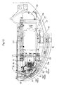
- a backhoe (an example of "swiveling work machine") 1 includes a traveling apparatus 3 having a pair of right and left crawler traveling members 2 and a swivel deck 4 mounted atop the traveling apparatus 3, with the swivel deck 4 being pivotable about a vertical pivot axis X via a swivel bearing 13. To the front end of the swivel deck 4, there is attached an implement 5.
- the implement 5 can be an excavator having a swing bracket 12 attached to the front end of the swivel deck 4 to be pivotable to the right/left, a boom 6 connected to the swing bracket 12 to be vertically pivotable, an arm 7 connected to the leading end of the boom 6 to be vertically pivotable, and a bucket 8 connected to the leading end of the boom 6 to be vertically pivotable.
- the swing bracket 12, the boom 6, the arm 7 and the bucket 8 are hydraulically operated by a boom cylinder 9, an arm cylinder 11 and a bucket cylinder 10, respectively.
- This implement 5 can include other work attachment than the bucket 8, such as a breaker.
- a rear hood (corresponding to "hood") 15, and forwardly of this rear hood 15, there is provided an operating section having a driver's seat, operational levers, operational pedals, etc.
- This operating section is surrounded by a cabin (an example of ROPS (rollover protection structure)) 17 provided at a front portion on the swivel deck 4.
- ROPS rollover protection structure
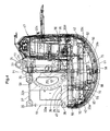
- a swivel base 19 in the form of a plate.
- this swivel base 19 there are disposed erect a pair of right and left vertical ribs 20R, 20L extending substantially along the fore and aft direction. More particularly, the two vertical ribs 20R, 20L are diverged or flared from the front side to the rear side of the swivel base 19.
- an upper plate 21 is fixed by e.g. welding.
- a lower plate 22 is fixed by e.g. welding.
- a support cylinder 23 is fixed by e.g. welding.
- the front portions of the pair of vertical ribs 20R, 20L, the front portion of the upper plate 21, the lower plate 22 and the support cylinder 23 together constitute a mounting bracket 24 for mounting the implement 5.
- This mounting bracket 24 extends forwardly from the swivel base 19.
- the swing bracket 12 (see Fig. 1 ) is connected via a vertical shaft (not shown), so that in association with extension/contraction of the swing cylinder (not shown), the swing bracket 12 and the implement 5 can be pivoted to the right/left about a vertical axis.
- a partitioning wall 26 extending in the right/left direction.
- an engine room 27 in which an engine 29, a radiator, etc. are disposed.
- an arcuate attaching wall 31 projects upwardly.
- a pair of right and left front cabin support members 35 for fixing thereto the front lower end of the cabin 17 and a pair of right and left rear cabin support members 36 for fixing thereto the rear lower end of the cabin 17.
- the right and left front cabin support members 35 are fixed respectively to the right and left sides of a support wall 37 disposed erect at the left front end portion of the swivel base 19 and the right and left rear cabin support members 36 are attached to the swivel base via stays (not shown).
- a counter weight 41 At the rear end of the swivel base 19, there is provided a counter weight 41. On the right and left opposed sides of this counter weight 41, there are provided side protectors 42 for protecting right and left corners of the rear end of the swivel deck 4.
- the cabin 17 is disposed at a front portion of one lateral side (the left front side thereof in this embodiment) of the swivel base 19, and the rear hood 15 is disposed at the rear portion of the swivel base 19. Further, at the front portion of the other lateral side of the swivel base 19 (the right front side thereof in this embodiment), a side hood 47 is provided.
- the rear hood 15 is disposed upwardly and forwardly of the counter weight 41 and on the right/left inner side of the pair of right and left side protectors 42.
- the counter weight 41, the pair of side protectors 42 and the rear hood 15 together constitute an engine room 27 surrounding the engine 29 over the rear end portion of the swivel base 19.
- the rear hood 15 comprises a front cover 49, a rear cover 50, a left side cover 51 and a right side cover 52 and the front side and the front upper side of the engine room 27 are covered by the front cover 49.
- a front upper portion of the rear cover 50 is supported via a hinge member 53 to be pivotable about a right/left axis, so that the rear cover 50 can be flipped up about its front end upper portion (right/left axis).
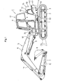
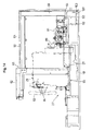
- the support frame 55 is provided within the rear hood 15.
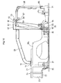
- This support frame 55 consists mainly of a left leg member 56, a right leg member 57, a rear leg member 58, a front leg member 59 and a support plate 60 connected to the respective upper ends of these leg members 56, 57, 58, 59 and the support frame 55 extends across and over the engine 44, i.e. striding over the engine 44.
- the support frame 55 includes, at upper portions thereof, the left cover member 61 and the right cover member 62 constituting the front cover 49 of the rear hood 15.
- the left leg member 56 of the support frame 55 is formed of an angular pipe or the like.
- the right leg member 57 is formed of a metal rod having an L-shaped cross section.
- the lower ends of the left leg member 56 and the right leg member 57 are fixedly attached, by attaching plates 64, 65, via the partitioning wall 36, etc., to the swivel base 19.
- the lower end of the rear leg member 58 is fixedly attached to the swivel base 19 by an attaching plate 66 via the attaching wall 31.
- the support plate 60 is a laterally elongate band plate-like member and the left end of this support plate 60 and the upper end of the left leg member 56 are fixedly connected to each other by e.g. welding.
- the right end of the support plate 60 and the upper end of the right leg member 57 are fixedly connected to each other by e.g. welding.
- the upper end of the rear leg member 58 is fixedly attached, via connecting plates 67, 68, to the rear end of the support plate 60 and the upper end of the right leg member 57.
- the upper end of the front leg member 59 is fixedly attached via the right cover member 62 to the upper end of the right leg member 57.
- the front leg member 59 of the support frame 55 is disposed on one lateral side (the right side in this embodiment) of the cabin 17 and extends forwardly along this lateral side to the vicinity of the front end of the swivel deck 4 (swivel base 19).
- the front leg member 59 is formed of a metal rod having a C-shaped cross section and projects forwardly from the upper end of the right leg member 57 of the support frame 55.
- the front leg member 59 extending upwardly of the vertical rib 20L is bent in a forwardly downward direction and projects significantly forwardly, with its front end being bent downward.
- the lower end portion (front end portion) of the front leg member 59 is fixed, via an attaching plate 71 and a connecting plate 72, to the upper face of the upper plate 21 attached to the forward upper faces of the vertical ribs 20R, 20L.
- the front portion of the front leg member 59 is disposed on the right outer side of the cabin 17 and the lower end portion (front end portion) of the front leg member 59 is fixed to the front end region of the swivel base 19 and the front leg member 59 is arranged between the cabin 17 and the side hood 47.
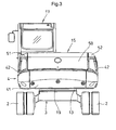
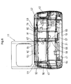
- the cabin 17 is mounted on the left side of the swivel base 19, with the rear end of the cabin 17 being placed on the rear hood 15. That is, as shown in Fig. 1 and Fig. 5 , at the rear end portion of the cabin 17, there is provided a mounting recess 63 which is formed concave from the lower side to the upper side so as to be placed on the rear hood 15.
- the cabin 17 is formed like a box having an open bottom and a lower end opening is provided at the lower end of the cabin 17 forwardly of the rear hood 15.
- a step (bottom plate) 69 is detachably attached, by means of bolts or the like, to the lower end opening edge of the cabin 17 so as to close the lower end opening of the cabin 17.
- Right and left two portions at the front end of the cabin 17 lower end are fixedly attached via anti-vibration elements to the front cabin support members 35.
- Right and rear two portions at the rear end of the cabin 17 lower end are fixedly attached via anti-vibration elements to the right and left cabin support members 36.
- right and left two portions of the mounting recess 63 of the cabin 17 are fixedly attached, via the front cover 49 (right cover member 62) of the hood 15 and a pair of right and left anti-vibration elements 70, to the upper face of the support plate 60 of the support frame 55.
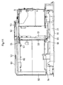
- a cover member 73 is provided for covering, from an upper side of the front leg member 59, a region between the cabin 17 and the side hood 47.
- a first inspection window 75 is provided in a rear end upper face of the cover member 73.
- a second inspection window 76 corresponding to the first inspection window 74 is provided in a front wall 15a of the rear hood 15 (front cover 49), and a lid member 78 for closing the first inspection window 75 and the second inspection window 76 is detachably attached to the cover member 73 by means of fixing members such as bolts.
- the rear wall 15a of the rear hood 15 is vertically disposed immediately forwardly of the support frame 55 and immediately rearwardly of the rear end of the cover member 73.
- the upper end of the front wall 15a is connected to e.g. the left cover member 61 or the right cover member 52 of the support frame 55, thereby to close the front side of the interior of the rear hood 15 (engine room 27).
- the front leg member 59 of the support frame 55 projects much more forwardly than the front wall 15a of the rear hood 15.
- the lid member 78 includes a first lid plate portion79 for covering the first inspection window 75 from the upper side thereof and a second lid plate portion 80 for covering the second inspection window 76 from the front side thereof, with the first and second plate portions 79, 80 together forming an L shape.
- the first lid plate portion 79 and the second lid plate portion 80 extend normal to each other to present an inverse L-shape in the side view.
- the first lid plate portion 79 includes a grip portion 81.
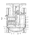
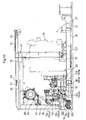
- the engine 29 is mounted with a lateral orientation (i.e. with its crankshaft extending along the right and left direction).
- This engine 29 is fixedly mounted, via anti-vibration elements or the like, to the partitioning wall 26 and the attaching wall 31.
- the engine 29 is disposed forwardly of the counter weight 41 and on the right side of the engine 29, a cooling fan 83 and the radiator are disposed.
- the cooling fan 83 is rotatably driven by power of the engine 29.
- an alternator 84 is provided at a front upper end of the right side of the engine 29 at a front upper end of the right side of the engine 29, an alternator 84 is provided.
- the second inspection window 76 is disposed at the position corresponding to the alternator 84. So that, with detachment of the lid member 78 from the cover member 73, the alternator 84 can be inspected through the first inspection window 75 and the second inspection window 76.
- a cutout recess 86 At the lower end of the second lid plate portion 80 of the lid member 78, there is provided a cutout recess 86, into which a heater hose 87 projecting from the engine 29 is inserted and the heater hose 87 is drawn out to the front side through the cutout recess 86 from the rear hood 15 (engine room 27).
- a flywheel 89 on the left side of the engine 29, there is provided a flywheel 89, and on its lateral side, there are disposed a first hydraulic pump 91, a second hydraulic pump 92 and a third hydraulic pump 93 for feeding working oil to the various hydraulic components (the hydraulic cylinders, 9, 10, 11, the hydraulic motor, control valves of the traveling apparatus 3, etc.).
- the first hydraulic pump 91 includes two LP pumps. These hydraulic pumps 91, 92, 93 are rotatably driven by the power of the engine 29.
- a line filter 95, a check valve 96 and an accumulator 97 Inside the rear hood 15 and on the left side of the engine 29, there are provided, as further hydraulic components, a line filter 95, a check valve 96 and an accumulator 97.
- an air cleaner 98 is provided at an upper portion of the left side of the engine 29. This air cleaner 98 is attached to the support plate 60 of the support frame 55 via an attaching stay 99.
- an unload valve for unloading the working oil discharged from the third hydraulic pump 93 is provided adjacent the lid member 78 disposed at the front portion of the rear hood 15.
- a signal block for transmitting signaling working oil to the various hydraulic components is provided, together with the unload valve, adjacent the lid member 78 disposed at the front portion of the rear hood 15.
- a hydraulic pipe 102 along the right/left direction.
- This hydraulic pipe 102 is connected to the working oil tank disposed inside the side hood 47 and also to the hydraulic pumps 91, 92, 93 so as to feed the working oil from the working oil tank to the hydraulic pumps 91, 92, 93.
- an air conditioning unit air conditioning body
- air conditioning pipes 101 (101a, 101b). Via these air conditioning pipes 101a, 101b, the air conditioning components inside the rear hood 15 and the air conditioning body outside the rear hood 15 are connected for circulating cooling medium between the air conditioning components and the air conditioning unit.
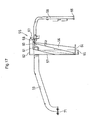
- an air conditioning pipe holding member 100 Inside the rear hood 15, there is provided an air conditioning pipe holding member 100.
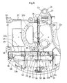
- This pipe holding member 100 is disposed on the left outer side of the engine 29 and adjacent the hydraulic pumps 91, 92, 93, so as to concentrate and hold the plurality of air conditioning pipes 101 (101a, 101b) and a plurality of hydraulic pipes 104 (104a, 104b, 104c, 104d, 104e) all together.
- this pipe holding member 100 includes an air conditioning pipe holding portion 103 for holding the plurality of air conditioning pipes 101 (101a, 101b) and a hydraulic pipe holding portion 105 for holding the plurality of hydraulic pipes 104 (104a, 104b, 104c, 104d, 104e), with the two holding portions 103, 105 being vertically superposed with each other.
- the air conditioning pipe holding portion 103 includes a pair of right and left support tables 107 fixed on the swivel base 19. And, between and upwardly of this pair of support tables 107, the hydraulic pipe holding portion 105 is provided, and the plural air conditioning pipes 101a, 10b are inserted between the pair of support tables 107 downwardly of the hydraulic pipe holding portion 105.
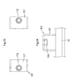
- the hydraulic pipe holding portion 105 includes a lower pipe holding member 108 and an upper pipe holding member 109, with the lower pipe holding member 108 being fixedly mounted on the air conditioning pipe holding portion 103 and the upper pipe holding member 109 being fixedly mounted on the lower pipe holding member 108.
- the lower pipe holding member 108 includes a pair of upper and lower pipe clamping members 111, 112, which are formed of rubber or synthetic resin having elasticity. And, these pipe clamping members 111, 112 form therebetween a plurality of insertion holes 113 for inserting the hydraulic pipes 104a, 104b, 104c.
- the upper and lower pair of pipe clamping members 111, 112 are vertically clamped with each other by means of an upper clamping plate 115 and a lower clamping plate 116, respectively, and are vertically fastened to each other via the upper and lower pair of clamping plates 115, 116 by means of fasteners 119.
- each fastener 119 can comprise a bolt 117 and a nut 118, for example.
- the nut 118 is fixedly attached to each support table 112 by means of welding or the like.
- Each fastener 119 is inserted through the pair of pipe clamping members 111, 112 and also through the cylindrical member 121, thus being inserted through the pair of upper and lower clamping plates 115, 116. Further, the pair of fasteners 119 are inserted into the support tables 107.
- the upper pipe holding member 109 includes a pipe holding body 124 defining a plurality of insertion holes 123 for inserting hydraulic pipes 104d, 104e and a press plate 125 disposed on the pipe holding body 124, so that the pipe holding body 124 may be vertically clamped by a fastener 127 between the press plate 125 and the upper clamping plate 115 of the lower pipe holding member 108.
- the fastener 127 includes a threaded cylinder 128 projecting upwardly from the upper clamping plate 115 and a bolt 129 to be threaded on the threaded cylinder 128. The threaded cylinder 128 is inserted and engaged through the insertion hole 131 of the pipe holding body 124 within this pipe holding body 124.
- the bolt 129 is inserted from above into the press plate 125 and threaded on the threaded cylinder 128. As the fastener 127 is fastened, the pipe holding body 124 is vertically clamped between the press plate 125 and the upper clamping plate 115 as described above.
- the hydraulic pipes 104a, 104b are pipes connected to a discharging side of the first hydraulic pump 91. These pipes 104a, 104b project from the first hydraulic pump 91 and are inserted and held in the lower pipe holding member 108 through the insertion holes 113 and then extend forwardly therefrom and are drawn out to the front side of the rear hood 15, thereby feeding working oil from the first hydraulic pump 91 to the various hydraulic components (the boom cylinder 9, the bucket cylinder 10, the arm cylinder 11, the hydraulic motor and control valves of the traveling apparatus 3, etc.).
- the hydraulic pipe 104c is a pipe connected to a discharging side of the second hydraulic pump 92.
- the hydraulic pipe 104c projects from the second hydraulic pump 92 and then is inserted and held within the lower pipe holding member 108 through the insertion hole 123 and then extends forwardly to be drawn out to the front side of the rear hood 15, feeding working oil from the first hydraulic pump 91 to the various hydraulic components (the boom cylinder 9, the bucket cylinder 10, the arm cylinder 11, the hydraulic motor and control valves of the traveling apparatus 3, etc.).
- the hydraulic pipe 104d is a pipe for signaling connecting between the signal block with the line filter 95 or the check valve 96.
- This pipe 104d projects from the line filter 95 or the check valve 96 and is inserted through and within the upper pipe holding member 109 through the insertion hole 123 and then extends forwardly to be drawn out to the front side of the rear hood 15 to be connected with the signal block.
- the hydraulic pipe 104e is a pipe connected to the check valve 96 and the unload valve. This pipe 104e projects from the check valve 96 and is inserted through and within the upper pipe holding member 109 through the insertion hole and then extends forwardly to be drawn out to the front side of the rear hood 15 to be connected with the unload valve.
- a discharging side of the third hydraulic pump 93 and the line filter 95 are connected to each other via an unillustrated hydraulic pipe, and the line filter 95 and the check valve 96 are connected to each other via an unillustrated hydraulic pipe.
- this front leg member 59 projects forwardly to be located on one lateral side of the cabin 17, this front leg member 59 extends by greater span in the fore and aft direction than the conventional construction. Therefore, even when the upper portion of the cabin 17 is subjected to a significant load to the front side, this front load can be sufficiently supported by the stiff projection of the front leg member 59, thus avoiding development of looseness of the support frame 55 to the front side.
- this front leg member 59 is formed of a metal rod having a C-shaped cross section, the nut or the like for attaching the cover member 73 can be readily and conveniently affixed to the rear side (lower side) of the front leg member 59.
- the first inspection window 75 provided at the rear end upper portion of the cover member 73 and the second inspection window 76 provided in the front wall 15a of the rear hood 15 can be opened and exposed at one time, thus allowing an operator's hand access to the alternator 84 through the first inspection window 75 and the second inspection window 76. And, it is also possible to draw out the alternator 84 altogether through the first inspection window 75 and the second inspection window 76 to the front side of the rear hood 15, whereby the inspection or maintenance of the alternator 84 can be carried out easily.
- the pipe holding member 100 for concentrating and holding the plural air conditioning pipes 101 and the plural hydraulic pipes 104 all together is disposed inside the hood 15, these air conditioning pipes 101 and the hydraulic pipes 104 can be held in a concentrated manner at one position inside the hood 15. Hence, the handling and laying out operations of these hydraulic pipes 104 and the air conditioning pipes 101 can be carried out easily as well.
- the entire pipe holding member 100 can be formed compact and also the plurality of air conditioning pipes 101 and the plurality of hydraulic pipes 104 can be laid out and fixed in a compact manner in a plurality of stages.
- the openings 33a of the swivel base 19 are provided adjacent the hydraulic pumps 91, 92, 93 and the pipe holding member 100, heat radiated from the hydraulic pumps 91, 92, 93 and the plurality of air conditioning pipes 101 and the plurality of hydraulic pipes 104 can be smoothly discharged through these openings 33a to the outside of the rear hood 15, thus effectively preventing accumulation and stagnation of such heat inside the rear hood 15.
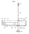
- Fig 25 shows a swiveling work machine according to a second embodiment of the present invention.
- the front leg member 59 of the support frame 55 is provided as a one-piece member.
- the front leg member 59 is constructed as an inter-bonded assembly of three metal rods 135, 136, 137 each having a C-shaped cross section and a linear shape, with the rods 135, 136, 137 being bonded together by means of welding or the like.
- the cabin 17as an example of ROPS is provided and the front portion of the cabin 17 is fixedly mounted on the swivel base 19 and the rear end of the cabin 17 is fixedly mounted on the upper portion of the support frame 55.
- the ROPS is not limited to such a cabin 17.
- any other type of ROPS such as a canopy, a safety frame, can be provided on the front side of the hood 15, and the front portion of this ROPS may be fixedly mounted on the swivel base 19 and the rear end of the ROPS may be fixedly mounted on the upper portion of the support frame 55.
- the arrangements of the components to be mounted on the swivel deck 4 can be reverse in the right/left direction.
- the ROPS such as the cabin 17 may be arranged on the right side of the swivel base 19 and the side hood 47 may be arranged on the left side thereof.
- a plurality of front leg members can be provided to extend respectively upwardly of a plurality of vertical ribs.
Claims (8)
- Eine schwenkende Arbeitsmaschine mit:einem Fahrgestell (3);einer Schwenkbasis (19), die auf dem Fahrgestell montiert ist, so dass sie um eine vertikale Achse (X) schwenkbar ist;einer Haube (15), die an einem rückwärtigen Abschnitt der Schwenkbasis angeordnet ist, wobei die Haube einen Motor (29) aufnimmt und einen Stützrahmen (55), der über den Motor hinweg angeordnet ist; undeiner Überrollschutzstruktur (Rollover Protection Structure - ROPS) (17), die ihr vorderes Ende an der Schwenkbasis (19) befestigt hat und ihr rückwärtiges Ende an einem oberen Abschnitt des Stützrahmens (55);dadurch gekennzeichnet,dass der genannten Stützrahmen (55) ein Vorderbeinelement (59) aufweist, das an einer seitlichen Seite der genannten ROPS (17) angeordnet ist, wobei das genannte Vorderbeinelement (59) sich in die Nähe des vorderen Endes der Schwenkbasis (19) erstreckt.
- Die schwenkende Arbeitsmaschine gemäß Anspruch 1,
dadurch gekennzeichnet,
dass die Schwenkbasis (19) eine Vertikalrippe (20L) umfasst, die auf ihr aufgerichtet angeordnet ist, wobei ein vorderes Ende des genannten Vorderbeinelementes (59) an einer vorderen Oberseite der genannten Vertikalrippe befestigt ist. - Die schwenkendes Arbeitsmaschine gemäß Anspruch 2,
dadurch gekennzeichnet,
dass eine obere Platte (21) an der vorderen Oberseite der Vertikalrippe befestigt ist und dass der vordere Endabschnitt des Vorderbeinelementes (59) an einer Oberseite der genannten oberen Platte (21) befestigt ist. - Die schwenkende Arbeitsmaschine gemäß Anspruch 2,
dadurch gekennzeichnet,
dass ein Schwenkhalteblech (12) für das schwenkbare Tragen eines Anbauelementes (5) an einem vorderen Ende der genannten Vertikalrippe (20L) angebracht ist, wobei ein vorderes Ende des genannten Vorderbeinelementes (59) in der Nähe einer Oberkante des genannten Schwenkhaltebleches (12) befestigt ist. - Die schwenkende Arbeitsmaschine gemäß Anspruch 1,
dadurch gekennzeichnet,
dass die genannte ROPS (17) an einem vorderen Abschnitt an einer seitlichen Seite der Schwenkbasis (19) vorgesehen ist und dass eine Seitenhaube (47) an einem vorderen Abschnitt der anderen seitlichen Seite der Schwenkbasis (19) vorgesehen ist, wobei das genannte Vorderbeinelement (59) sich zwischen der genannten Seitenhaube (47) und der genannten ROPS (17) erstreckt. - Die schwenkende Arbeitsmaschine gemäß Anspruch 5,
dadurch gekennzeichnet,
dass ein Abdeckelement (73) vorgesehen ist, um von einer Oberseite des Vorderbeinelementes (49) einen Bereich zwischen der genannten ROPS (17) und der genannten Seitenhaube (47) abzudecken;
wobei ein erstes Inspektionsfenster (75) vorgesehen ist an einer rückwärtigen Oberseite des Abdeckelementes (73);
und wobei ein zweites Inspektionsfenster (76), das mit dem genannten ersten Inspektionsfenster (75) korrespondiert, an einer Vorderwand der genannten Haube (15) vorgesehen ist; und
und wobei ein Deckelelement (78) lösbar an dem genannten Abdeckelement (73) angebracht ist, um das genannte erste Inspektionsfenster (75) und das genannte zweite Inspektionsfenster (76) zu schließen. - Die schwenkende Arbeitsmaschine gemäß Anspruch 6,
dadurch gekennzeichnet,
dass das genannte Deckelelement (78) einen ersten Deckelplattenabschnitt (79) aufweist, um das genannte erste Inspektionsfenster (75) von oben her abzudecken, und einen zweiten Deckelplattenabschnitt (80), um das genannte zweite Inspektionsfenster (76) von seiner Vorderseite aus abzudecken, wobei der erste Deckelplattenabschnitt (79) und der zweite L7eckelplattenabschnitt (80) normal zueinander verlaufen. - Die schwenkende Arbeitsmaschine gemäß Anspruch 7,
dadurch gekennzeichnet,
dass der genannte Motor (29) eine Lichtmaschine (84) aufweist, wobei das genannte zweite Inspektionsfenster (76) an einer Stelle angebracht ist, die zu der genannten Lichtmaschine (84) korrespondiert, wobei die genannte Lichtmaschine (84) durch das genannte erste Inspektionsfenster (75) und durch das zweite Inspektionsfenster (76) inspizierbar ist, wenn das Deckelelement (78) von dem genannten Abdeckelement (73) gelöst ist.
Applications Claiming Priority (1)
| Application Number | Priority Date | Filing Date | Title |
|---|---|---|---|
| JP2005092855A JP4619168B2 (ja) | 2005-03-28 | 2005-03-28 | 旋回作業機 |
Publications (2)
| Publication Number | Publication Date |
|---|---|
| EP1707688A1 EP1707688A1 (de) | 2006-10-04 |
| EP1707688B1 true EP1707688B1 (de) | 2009-07-29 |
Family
ID=36591322
Family Applications (1)
| Application Number | Title | Priority Date | Filing Date |
|---|---|---|---|
| EP06005021A Active EP1707688B1 (de) | 2005-03-28 | 2006-03-11 | Drehbare Baumaschine |
Country Status (5)
| Country | Link |
|---|---|
| US (1) | US7717218B2 (de) |
| EP (1) | EP1707688B1 (de) |
| JP (1) | JP4619168B2 (de) |
| CN (1) | CN1840786B (de) |
| DE (1) | DE602006008055D1 (de) |
Families Citing this family (25)
| Publication number | Priority date | Publication date | Assignee | Title |
|---|---|---|---|---|
| WO2004076265A1 (ja) * | 2003-02-27 | 2004-09-10 | Komatsu Ltd. | 後端小旋回油圧ショベル |
| JP4120530B2 (ja) * | 2003-08-21 | 2008-07-16 | コベルコ建機株式会社 | 建設機械のサポート柱取付方法 |
| KR100693978B1 (ko) * | 2004-11-19 | 2007-03-12 | 가부시끼 가이샤 구보다 | 선회 작업기 |
| KR100689293B1 (ko) * | 2005-07-25 | 2007-03-02 | 볼보 컨스트럭션 이키프먼트 홀딩 스웨덴 에이비 | 건설기계의 운전실 캡을 지지하는 상부프레임 구조 |
| JP4655815B2 (ja) * | 2005-08-12 | 2011-03-23 | コベルコ建機株式会社 | 建設機械のキャビン |
| KR101134057B1 (ko) * | 2006-10-16 | 2012-04-13 | 가부시키가이샤 고마쓰 세이사쿠쇼 | 파이프의 보강 구조 및 이것을 구비한 건설 기계의 캡 |
| JP4686565B2 (ja) * | 2008-03-31 | 2011-05-25 | 株式会社クボタ | 作業機の上部構造 |
| JP5061085B2 (ja) * | 2008-11-17 | 2012-10-31 | 株式会社クボタ | 旋回作業機のボンネットシール構造 |
| US8267217B2 (en) * | 2009-09-29 | 2012-09-18 | Kubota Corporation | Swivel frame |
| JP5077410B2 (ja) * | 2010-09-14 | 2012-11-21 | コベルコ建機株式会社 | 建設機械の支柱取付構造 |
| JP5077411B2 (ja) * | 2010-09-14 | 2012-11-21 | コベルコ建機株式会社 | 建設機械における機器類の脱着構造及び同脱着方法 |
| JP5228093B2 (ja) * | 2011-07-29 | 2013-07-03 | 株式会社小松製作所 | 油圧ショベル |
| JP5758338B2 (ja) * | 2012-03-29 | 2015-08-05 | 株式会社クボタ | 作業機 |
| JP5923391B2 (ja) * | 2012-06-11 | 2016-05-24 | 株式会社クボタ | 作業機 |
| US8662219B2 (en) * | 2012-07-19 | 2014-03-04 | Komatsu Ltd. | Work vehicle |
| JP5856920B2 (ja) * | 2012-08-06 | 2016-02-10 | 株式会社クボタ | 作業機 |
| JP6028588B2 (ja) * | 2013-01-22 | 2016-11-16 | コベルコ建機株式会社 | 作業機械 |
| WO2014125623A1 (ja) * | 2013-02-15 | 2014-08-21 | 株式会社小松製作所 | 油圧ショベル |
| US10550545B2 (en) * | 2014-12-12 | 2020-02-04 | Komatsu Ltd. | Work vehicle |
| WO2017068734A1 (ja) | 2015-10-23 | 2017-04-27 | 株式会社小松製作所 | トラクタ |
| JP6560640B2 (ja) * | 2016-04-20 | 2019-08-14 | 株式会社日立建機ティエラ | 小型油圧ショベル |
| WO2019131721A1 (ja) | 2017-12-27 | 2019-07-04 | 株式会社クボタ | 作業機及び作業機の製造方法 |
| JP6847822B2 (ja) * | 2017-12-27 | 2021-03-24 | 株式会社クボタ | 作業機 |
| JP6922960B2 (ja) * | 2019-09-26 | 2021-08-18 | コベルコ建機株式会社 | 建設機械 |
| CN113653123B (zh) * | 2021-09-23 | 2022-08-23 | 扬州扬子到河复合材料制品有限公司 | 一种多功能挖掘机工具箱后罩及其加工工艺 |
Family Cites Families (19)
| Publication number | Priority date | Publication date | Assignee | Title |
|---|---|---|---|---|
| US1883464A (en) * | 1932-01-08 | 1932-10-18 | Briggs Mfg Co | Ventilator construction |
| US2805887A (en) * | 1956-02-10 | 1957-09-10 | Ernest E Selby | Tractor canopy guard and combination |
| FR2488206B1 (fr) * | 1980-08-07 | 1985-07-12 | Poclain Sa | Chassis porteur d'un engin mobile a bati central et longerons |
| CN1161725A (zh) * | 1994-11-08 | 1997-10-08 | 株式会社小松制作所 | 作业车辆 |
| JP3572719B2 (ja) * | 1995-05-16 | 2004-10-06 | コベルコ建機株式会社 | 油圧作業機 |
| JPH09228417A (ja) * | 1996-02-28 | 1997-09-02 | Kubota Corp | バックホウ |
| JP3155463B2 (ja) * | 1996-05-28 | 2001-04-09 | 株式会社クボタ | 作業機の支持フレーム構造 |
| JP3645400B2 (ja) | 1997-06-03 | 2005-05-11 | 日立建機株式会社 | 旋回式建設機械 |
| JP2001040706A (ja) * | 1999-08-03 | 2001-02-13 | Komatsu Ltd | 建設機械の旋回台 |
| US6481748B1 (en) * | 1999-07-30 | 2002-11-19 | Komatsu Ltd. | Counterweight for construction vehicle |
| JP4756291B2 (ja) * | 2000-08-11 | 2011-08-24 | 株式会社豊田自動織機 | バッテリ式トーイングトラクタ |
| JP4246360B2 (ja) | 2000-08-24 | 2009-04-02 | 日立建機株式会社 | 旋回式建設機械 |
| JP2003064724A (ja) | 2001-08-28 | 2003-03-05 | Kubota Corp | 旋回作業機 |
| JP2003074085A (ja) * | 2001-08-30 | 2003-03-12 | Kubota Corp | 旋回作業機 |
| JP4003503B2 (ja) * | 2002-03-27 | 2007-11-07 | コベルコ建機株式会社 | 小旋回型ショベル |
| JP2004076455A (ja) * | 2002-08-20 | 2004-03-11 | Hitachi Constr Mach Co Ltd | 旋回式建設機械 |
| JP4211919B2 (ja) * | 2003-03-24 | 2009-01-21 | 株式会社小松製作所 | 油圧ショベルのカウンタウエイト |
| JP3956907B2 (ja) * | 2003-06-24 | 2007-08-08 | コベルコ建機株式会社 | 小型ショベル |
| JP4226546B2 (ja) | 2004-03-29 | 2009-02-18 | 株式会社クボタ | 旋回作業機 |
-
2005
- 2005-03-28 JP JP2005092855A patent/JP4619168B2/ja active Active
-
2006
- 2006-03-08 US US11/371,341 patent/US7717218B2/en active Active
- 2006-03-11 EP EP06005021A patent/EP1707688B1/de active Active
- 2006-03-11 DE DE602006008055T patent/DE602006008055D1/de active Active
- 2006-03-28 CN CN2006100715368A patent/CN1840786B/zh not_active Expired - Fee Related
Also Published As
| Publication number | Publication date |
|---|---|
| CN1840786B (zh) | 2010-08-11 |
| EP1707688A1 (de) | 2006-10-04 |
| DE602006008055D1 (de) | 2009-09-10 |
| JP4619168B2 (ja) | 2011-01-26 |
| JP2006274594A (ja) | 2006-10-12 |
| US7717218B2 (en) | 2010-05-18 |
| US20060226680A1 (en) | 2006-10-12 |
| CN1840786A (zh) | 2006-10-04 |
Similar Documents
| Publication | Publication Date | Title |
|---|---|---|
| EP1707688B1 (de) | Drehbare Baumaschine | |
| US7416219B2 (en) | Swiveling work machine | |
| US7320380B2 (en) | Swiveling utility machine having swivel deck | |
| US7481289B2 (en) | Swiveling work machine | |
| US20110017537A1 (en) | Working Vehicle | |
| US8083019B2 (en) | Upper assembly structure of work machine | |
| US7021074B2 (en) | Work vehicle | |
| US20090084003A1 (en) | Excavating Machine | |
| JP6537994B2 (ja) | 作業機 | |
| EP1462578A2 (de) | Baumaschine | |
| US20060185200A1 (en) | Rear end small revolving type hydraulic shovel | |
| JP4619169B2 (ja) | 旋回作業機 | |
| JP3691750B2 (ja) | 旋回作業機 | |
| JP6572162B2 (ja) | 作業機及び作業機のキャビン | |
| JP6572163B2 (ja) | 作業機 | |
| JP6847911B2 (ja) | 作業機 | |
| JP3693480B2 (ja) | 油圧ショベルの上部旋回体 | |
| JPH10140613A (ja) | 建設機械 | |
| JP6537993B2 (ja) | 作業機 | |
| KR100363487B1 (ko) | 백호 | |
| EP4317598A1 (de) | Arbeitsmaschine | |
| JP7326221B2 (ja) | 作業機 | |
| JP4346428B2 (ja) | 旋回作業機 | |
| JP2877717B2 (ja) | 旋回作業機の上部構造 | |
| JP2007204993A (ja) | 作業車のキャノピ |
Legal Events
| Date | Code | Title | Description |
|---|---|---|---|
| PUAI | Public reference made under article 153(3) epc to a published international application that has entered the european phase |
Free format text: ORIGINAL CODE: 0009012 |
|
| 17P | Request for examination filed |
Effective date: 20060311 |
|
| AK | Designated contracting states |
Kind code of ref document: A1 Designated state(s): AT BE BG CH CY CZ DE DK EE ES FI FR GB GR HU IE IS IT LI LT LU LV MC NL PL PT RO SE SI SK TR |
|
| AX | Request for extension of the european patent |
Extension state: AL BA HR MK YU |
|
| AKX | Designation fees paid |
Designated state(s): DE FR GB IT |
|
| GRAP | Despatch of communication of intention to grant a patent |
Free format text: ORIGINAL CODE: EPIDOSNIGR1 |
|
| GRAS | Grant fee paid |
Free format text: ORIGINAL CODE: EPIDOSNIGR3 |
|
| GRAA | (expected) grant |
Free format text: ORIGINAL CODE: 0009210 |
|
| AK | Designated contracting states |
Kind code of ref document: B1 Designated state(s): DE FR GB IT |
|
| REG | Reference to a national code |
Ref country code: GB Ref legal event code: FG4D |
|
| REF | Corresponds to: |
Ref document number: 602006008055 Country of ref document: DE Date of ref document: 20090910 Kind code of ref document: P |
|
| PLBE | No opposition filed within time limit |
Free format text: ORIGINAL CODE: 0009261 |
|
| STAA | Information on the status of an ep patent application or granted ep patent |
Free format text: STATUS: NO OPPOSITION FILED WITHIN TIME LIMIT |
|
| 26N | No opposition filed |
Effective date: 20100503 |
|
| REG | Reference to a national code |
Ref country code: FR Ref legal event code: PLFP Year of fee payment: 11 |
|
| REG | Reference to a national code |
Ref country code: FR Ref legal event code: PLFP Year of fee payment: 12 |
|
| REG | Reference to a national code |
Ref country code: FR Ref legal event code: PLFP Year of fee payment: 13 |
|
| PGFP | Annual fee paid to national office [announced via postgrant information from national office to epo] |
Ref country code: FR Payment date: 20230208 Year of fee payment: 18 |
|
| PGFP | Annual fee paid to national office [announced via postgrant information from national office to epo] |
Ref country code: IT Payment date: 20230213 Year of fee payment: 18 Ref country code: GB Payment date: 20230202 Year of fee payment: 18 Ref country code: DE Payment date: 20230131 Year of fee payment: 18 |