EP1700651A1 - Verfahren und Vorrichtung zur Herstellung eines Werkstückes mit Innenverzahnung, insbesondere eines Hohlrades - Google Patents
Verfahren und Vorrichtung zur Herstellung eines Werkstückes mit Innenverzahnung, insbesondere eines Hohlrades Download PDFInfo
- Publication number
- EP1700651A1 EP1700651A1 EP06007394A EP06007394A EP1700651A1 EP 1700651 A1 EP1700651 A1 EP 1700651A1 EP 06007394 A EP06007394 A EP 06007394A EP 06007394 A EP06007394 A EP 06007394A EP 1700651 A1 EP1700651 A1 EP 1700651A1
- Authority
- EP
- European Patent Office
- Prior art keywords
- ironing
- preform
- plunger
- side wall
- during
- Prior art date
- Legal status (The legal status is an assumption and is not a legal conclusion. Google has not performed a legal analysis and makes no representation as to the accuracy of the status listed.)
- Pending
Links
- 238000000034 method Methods 0.000 title claims abstract description 18
- 238000004519 manufacturing process Methods 0.000 title abstract description 6
- 238000010409 ironing Methods 0.000 claims description 41
- 230000001105 regulatory effect Effects 0.000 claims description 4
- 125000006850 spacer group Chemical group 0.000 claims description 2
- 238000005096 rolling process Methods 0.000 description 1
Images




Classifications
-
- B—PERFORMING OPERATIONS; TRANSPORTING
- B21—MECHANICAL METAL-WORKING WITHOUT ESSENTIALLY REMOVING MATERIAL; PUNCHING METAL
- B21J—FORGING; HAMMERING; PRESSING METAL; RIVETING; FORGE FURNACES
- B21J5/00—Methods for forging, hammering, or pressing; Special equipment or accessories therefor
- B21J5/02—Die forging; Trimming by making use of special dies ; Punching during forging
-
- B—PERFORMING OPERATIONS; TRANSPORTING
- B21—MECHANICAL METAL-WORKING WITHOUT ESSENTIALLY REMOVING MATERIAL; PUNCHING METAL
- B21J—FORGING; HAMMERING; PRESSING METAL; RIVETING; FORGE FURNACES
- B21J5/00—Methods for forging, hammering, or pressing; Special equipment or accessories therefor
- B21J5/06—Methods for forging, hammering, or pressing; Special equipment or accessories therefor for performing particular operations
- B21J5/12—Forming profiles on internal or external surfaces
-
- B—PERFORMING OPERATIONS; TRANSPORTING
- B21—MECHANICAL METAL-WORKING WITHOUT ESSENTIALLY REMOVING MATERIAL; PUNCHING METAL
- B21K—MAKING FORGED OR PRESSED METAL PRODUCTS, e.g. HORSE-SHOES, RIVETS, BOLTS OR WHEELS
- B21K1/00—Making machine elements
- B21K1/28—Making machine elements wheels; discs
- B21K1/30—Making machine elements wheels; discs with gear-teeth
Definitions
- the invention relates to a method and an apparatus for producing a workpiece with internal toothing, in particular a ring gear, according to the preamble of the first and eighteenth claim.
- internal gears are generated for example by pressure-rolling.
- a cup-shaped preform is gem. DE 198 30 817 A1 pressed by means of tapered rollers during a feed movement against a tool chuck, which has the outer profile of the internal toothing to be generated, and reduced in diameter, wherein the preform rotates relative to the tapered rollers.
- the material of the cylinder wall region of the preform flows into the profile of the tool chuck, whereby the inner profile of the workpiece is generated.
- JP 61 038732 A describes the production of a workpiece with internal teeth by means of ironing, wherein an upper die lowered and thus a further die against a cup-shaped preform whose bottom has an elongated upper die in the direction of the upper die is pressed.
- the face of the preform is seated during the downward movement on a stop of the mandrel, which in turn is held shock-damped by hydraulic cylinders. Due to the very specific training the preform or the workpiece and, accordingly, the tool, this device is only limited use.
- the object of the invention is to provide a method and apparatus for energy-saving production of a workpiece with internal teeth, in particular a ring gear, which ensure a significant increase in productivity with high quality of internal teeth in a relatively simple structural design of the device.
- the device for producing a workpiece with internal teeth in particular a ring gear, using a cup-shaped preform having a substantially cylindrical side wall and has a mandrel with an outer profile corresponding to the internal teeth to be generated, and a forming tool, which during an advancing movement, the outer diameter of the cylindrical side wall reduced, whereby the material of the cylindrical side wall flows into the outer profile (6) of the mandrel, according to the invention the forming tool is formed as a in a feed movement ironing the cylindrical side wall ensuring Ziehring, wherein in the direction of the end face of the preform an axially movable plunger with a axial force acts.
- the drawing ring ensures during a feed movement ironing of the cylinder wall area patiian the preform during the ironing two attack in the cylindrical side wall of the preform axial compressive stress generating tool elements, and towards the end face of the cylindrical side wall of the preform a first tool element in the form of an axially movable, as a cylindrical pressure sleeve formed plunger is arranged such that it acts during ironing on the end face with the axial force.
- an axially movable counter-holder is arranged such that it acts during ironing on the underside of the bottom of the preform with a counter-holding force.
- the counter-holder can have a circular pressure surface pointing in the direction of the underside of the base, which acts essentially on the entire bottom region, or an annular pressure surface, which is adapted to the width of the cylinder wall of the preform and aligned substantially flush with it, and onto the edge region of the preform Bottom of the bottom of the preform acts.
- the pressure stamp is axially movable in the direction of the advancing movement of the drawing ring by a movement corresponding to the ironing length of the preform.
- the axial lifting movement of the plunger during ironing can be regulated as a function of its axial force.
- the plunger is mounted axially movable via a hydraulic piston.
- the device may advantageously be integrated in a hydraulic press, consisting of a press table and a press ram.
- the mandrel is arranged axially fixed on the press table and mounted on the mandrel, axially displaceable via a hydraulic piston, the plunger.
- the plunger At the press ram of the pull ring are preferably fixed to the frame and the counter-holder preferably arranged axially movable via a hydraulic piston.
- the plunger is preferred as a cylindrical. Pressure sleeve formed. The distance of the pressure surface of the plunger to the end face of the mandrel adapted to the length of the preform is e.g. adjustable via spacer rings.
- the mandrel For ejecting the workpiece, the mandrel is rotatably mounted when producing a helical toothing.
- one or both sides can be arranged at the end of the workpiece, a material overflow.
- the material overflow is provided for example in the counter-holder or can be formed in the adapter in which the plunger is mounted.
- the production of the workpiece with internal teeth characterized in that a cup-shaped preform, having a bottom and a substantially cylindrical side wall, over a mandrel, which has the outer profile corresponding to the internal teeth to be generated, is reduced in its outer diameter, so that material of Cylinder wall portion flows into the outer profile of the mandrel, wherein according to the invention reducing the outer diameter by ironing done by means of a draw ring and during the ironing additional axial pressure is applied to the cylindrical side wall of the preform.
- the axial pressure is generated by two acting on both sides of the region of the cylindrical side wall tool elements, wherein in the direction of the end face of the cylindrical side wall of the preform a first tool element in the form of an axially movable, designed as a cylindrical pressure sleeve, plunger during Abstreck horrs on the end face with a force acts.
- axial compressive stresses are applied to the cylindrical side wall of the preform by the axial pressure so that the flow of material into the profile of the mandrel is promoted.
- a counter-holder acts on the underside of the floor to avoid deformations in the floor area and to apply an opposing force.
- the counter-holding force of the counter-holder and the force of the plunger should be mutually adjustable so that during the entire Abstreckvorganges a flow of material is ensured in the radial direction to completely fill the contour of the mandrel.
- the plunger performs an axial stroke movement corresponding to the ironing length of the preform in the direction of the advancing movement of the drawing ring, which is regulated as a function of its pressure force.
- the counter-holding force of the counter-holder and the force of the plunger are in this case adjustable in relation to one another such that a material foot in the radial direction is ensured for the complete filling of the contour of the mandrel during the entire ironing process
- the productivity can be increased by 4 to 6 times in comparison to the spin forming.
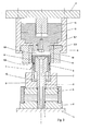
- Fig. 1 and 2 the basic structure of the device integrated in a press is shown.
- the lower tool part 2 On the press table 1, the lower tool part 2 is arranged, which has a first hydraulic piston 3.
- a punch 4 of the mandrel 5 On the lower tool part 2 is axially fixed on a punch 4 of the mandrel 5 is fixed, which has an outer profile 6.
- the hydraulic piston 3 is mounted on an adapter 8 of the printing sleeve designed as a pressure piston 9 axially movable. The axial position of the plunger 9 can be changed over distances 10, the between adapter 8 and plunger 9 are attached.
- the tool upper part 11 is arranged on the press ram P and has a counter-holder 12, which is axially adjustable via a second hydraulic piston 13.
- the drawing ring 14 is further fixed to the frame via an adapter 15.
- Gem. Fig. 1 the cup-shaped preform N was inserted with the cylindrical side wall N1 down over the mandrel 5, so that the end face N2 in the direction of the plunger 9 and the bottom of the bottom N3 in the direction of the anvil 12 has.
- the hydraulic piston 13 moves the counter-holder 12 in the direction of the tool lower part until the counter-holder 12 rests against the underside of the base N3.
- the frame-mounted on the press ram P frame 14 moves in the forward stroke with the press ram P in the direction of the press table 1, simultaneously the first hydraulic piston 3 is pressurized and presses the plunger 9 with the force F1 against the end face N2 of the preform N (Fig. 2).
- the counter-holder 12 exerts a counterhold force F2 on the bottom of the cup.
- the plunger 9, corresponding to the ironing of the preform N makes a movement in the direction of the preliminary stroke of the drawing ring 14, the pressure acting on the side wall N1 being maintained by the forces F1 and F2.
- the material flow is favored so that material flows reliably into the profile 6 of the mandrel 5. This ensures excellent quality of the internal teeth.
- After completion of the ironing pulls the tool upper part 11 upwards and the workpiece is released via the ejector 7 from the mandrel 5, which is rotatably supported at a helical toothing.
- Fig. 3 and 4 in the counter-holder 12 provide a material overflow 12.2.
- the counter-holder 12 has in the direction of the preform N a pressure piece 12.1, which is also reduced in the direction of the preform N in diameter, so that between pressure piece 12.1 and adapter 15 creates a gap into which the excess material can flow and thus serves as a material overflow 12.2.
- FIG. 5 it is also possible, in addition to the material overflow 12.2 provided in FIGS. 3 and 4, to arrange a further material overflow 12.3 at the end of the cylindrical side wall N1.
- the gap between the outer diameter of the plunger 9 and the inner diameter of the draw ring 14 are used.
- an increased axial pressure is exerted for calibrating in order to achieve a better filling and a higher accuracy of the internal toothing. The possibly excess material can flow off as described above.
- the increased pressure can now be applied, for example, by the pressure piston 9 being connected to a threaded ring G1 via an intermediate piece Z which has threads G at its outer diameter and which in turn is connected to the cylinder 3.1 and thus via the lower tool part 2 the press table 1 is supported.
Landscapes
- Engineering & Computer Science (AREA)
- Mechanical Engineering (AREA)
- Shaping Metal By Deep-Drawing, Or The Like (AREA)
- Forging (AREA)
- Gears, Cams (AREA)
- Blow-Moulding Or Thermoforming Of Plastics Or The Like (AREA)
- Turning (AREA)
Applications Claiming Priority (2)
| Application Number | Priority Date | Filing Date | Title |
|---|---|---|---|
| DE10054399A DE10054399A1 (de) | 2000-11-02 | 2000-11-02 | Verfahren und Vorrichtung zur Herstellung eines Werkstückes mit Innenverzahnung, insbesondere eines Hohlrades |
| EP01992620A EP1330320B1 (de) | 2000-11-02 | 2001-11-01 | Verfahren und vorrichtung zur herstellung eines werkstückes mit innenverzahnung, insbesondere eines hohlrades |
Related Parent Applications (1)
| Application Number | Title | Priority Date | Filing Date |
|---|---|---|---|
| EP01992620A Division EP1330320B1 (de) | 2000-11-02 | 2001-11-01 | Verfahren und vorrichtung zur herstellung eines werkstückes mit innenverzahnung, insbesondere eines hohlrades |
Publications (1)
| Publication Number | Publication Date |
|---|---|
| EP1700651A1 true EP1700651A1 (de) | 2006-09-13 |
Family
ID=7661964
Family Applications (2)
| Application Number | Title | Priority Date | Filing Date |
|---|---|---|---|
| EP06007394A Pending EP1700651A1 (de) | 2000-11-02 | 2001-11-01 | Verfahren und Vorrichtung zur Herstellung eines Werkstückes mit Innenverzahnung, insbesondere eines Hohlrades |
| EP01992620A Expired - Lifetime EP1330320B1 (de) | 2000-11-02 | 2001-11-01 | Verfahren und vorrichtung zur herstellung eines werkstückes mit innenverzahnung, insbesondere eines hohlrades |
Family Applications After (1)
| Application Number | Title | Priority Date | Filing Date |
|---|---|---|---|
| EP01992620A Expired - Lifetime EP1330320B1 (de) | 2000-11-02 | 2001-11-01 | Verfahren und vorrichtung zur herstellung eines werkstückes mit innenverzahnung, insbesondere eines hohlrades |
Country Status (8)
| Country | Link |
|---|---|
| US (1) | US7231799B2 (https=) |
| EP (2) | EP1700651A1 (https=) |
| JP (1) | JP2004512956A (https=) |
| KR (1) | KR100833771B1 (https=) |
| AT (1) | ATE322948T1 (https=) |
| AU (1) | AU2002215846A1 (https=) |
| DE (2) | DE10054399A1 (https=) |
| WO (1) | WO2002036287A1 (https=) |
Families Citing this family (11)
| Publication number | Priority date | Publication date | Assignee | Title |
|---|---|---|---|---|
| WO2004094083A2 (de) * | 2003-04-22 | 2004-11-04 | Neumayer Tekfor Gmbh | Verfahren zur herstellung eines napfförmigen ringteiles mit innenverzahnung, napfförmige vorform und napfförmiges ringteil |
| US20070125147A1 (en) * | 2005-12-06 | 2007-06-07 | Yahya Hodjat | Method of forming a part |
| CN100381221C (zh) * | 2006-06-16 | 2008-04-16 | 重庆工学院 | 基于粘性介质传力的板料无模多点成形装置及方法 |
| CN101947621B (zh) * | 2010-07-05 | 2012-07-25 | 南京中盛铁路车辆配件有限公司 | 锻造钩尾框整形模 |
| CN102389913A (zh) * | 2011-10-25 | 2012-03-28 | 南通皋液液压机有限公司 | 一种高铁车厢尾钩框架整形液压机 |
| KR101698305B1 (ko) * | 2011-12-21 | 2017-01-19 | 유틸 (광저우) 오토 파츠 씨오.,엘티디. | 철재 지지대의 양방향 동시적 드로우룸 및 그 사용 방법 |
| DE102011122144B4 (de) | 2011-12-22 | 2022-11-24 | Volkswagen Aktiengesellschaft | Vorrichtung und Verfahren zur spanlosen, axial umformenden Ausbildung einer Innenverzahnung an einem Werkstück |
| JP5969234B2 (ja) * | 2012-03-23 | 2016-08-17 | アイシン・エィ・ダブリュ株式会社 | 自動変速機のシリンダ部材製造方法 |
| US9302318B2 (en) * | 2014-12-14 | 2016-04-05 | Griffin Tactical Incorporated | Device and method for construction of baffles from engine block freeze plugs |
| KR101764857B1 (ko) * | 2017-02-14 | 2017-08-03 | 김금자 | 자동차용 매니폴드 제작공정 및 그 제작금형 |
| CN115229017B (zh) * | 2022-06-24 | 2024-06-21 | 中国石油大学(华东) | 一种异形对轮旋压机 |
Citations (10)
| Publication number | Priority date | Publication date | Assignee | Title |
|---|---|---|---|---|
| US3694127A (en) * | 1969-12-01 | 1972-09-26 | Hitachi Powdered Metals | Powder compacting device for forming helical gear compact |
| DE2308428A1 (de) | 1973-02-21 | 1974-08-29 | Diehl Fa | Hartkerngeschoss |
| DE2308420A1 (de) * | 1973-02-21 | 1974-10-10 | Schmalbach Lubeca | Einendig offener behaelter aus metall |
| US3899912A (en) * | 1972-07-10 | 1975-08-19 | Glaenzer Spicer Sa | Method and device for cold-forming rolling elements |
| DE2542823A1 (de) * | 1975-09-25 | 1977-03-31 | Fritz Werner Ind Ausruestung | Verfahren und rundknetmaschine zum innenprofilieren rohrfoermiger werkstuecke mit einseitiger querschnittserweiterung des innenprofiles |
| JPS5816727A (ja) * | 1981-07-24 | 1983-01-31 | Mitsubishi Heavy Ind Ltd | ネジ状部品の成形方法およびその装置 |
| JPS6138732A (ja) | 1984-07-31 | 1986-02-24 | Toyota Motor Corp | 自在継手外輪のクロス溝形成方法及びその装置 |
| DE3639739A1 (de) * | 1986-11-21 | 1988-06-01 | Honda Motor Co Ltd | Verfahren und vorrichtung zur herstellung eines eine innenzahnung aufweisenden topffoermigen erzeugnisses |
| JPH01317653A (ja) * | 1988-06-15 | 1989-12-22 | Honda Motor Co Ltd | 内歯付きカップ状製品の成形方法 |
| DE19830817A1 (de) | 1998-07-09 | 1998-12-10 | Leico Werkzeugmaschb Gmbh & Co | Verfahren zum Umformen eines Werkstücks durch Drückwalzen |
Family Cites Families (3)
| Publication number | Priority date | Publication date | Assignee | Title |
|---|---|---|---|---|
| GB1373547A (en) * | 1970-11-24 | 1974-11-13 | Renault | Methods of manufacturing helical gear blanks by cold extrusion process |
| JP2832326B2 (ja) * | 1992-07-14 | 1998-12-09 | 大岡技研株式会社 | 歯形の成形装置及びその装置を使用する歯形成形方法 |
| DE4412224A1 (de) * | 1994-04-09 | 1995-10-12 | Graebener Pressensysteme Gmbh | Presse für eine Kaltverformung von Metallwerkstücken |
-
2000
- 2000-11-02 DE DE10054399A patent/DE10054399A1/de not_active Withdrawn
-
2001
- 2001-11-01 US US10/415,637 patent/US7231799B2/en not_active Expired - Fee Related
- 2001-11-01 AT AT01992620T patent/ATE322948T1/de not_active IP Right Cessation
- 2001-11-01 JP JP2002539085A patent/JP2004512956A/ja active Pending
- 2001-11-01 DE DE50109512T patent/DE50109512D1/de not_active Expired - Fee Related
- 2001-11-01 EP EP06007394A patent/EP1700651A1/de active Pending
- 2001-11-01 KR KR1020037005827A patent/KR100833771B1/ko not_active Expired - Fee Related
- 2001-11-01 EP EP01992620A patent/EP1330320B1/de not_active Expired - Lifetime
- 2001-11-01 WO PCT/DE2001/004192 patent/WO2002036287A1/de not_active Ceased
- 2001-11-01 AU AU2002215846A patent/AU2002215846A1/en not_active Abandoned
Patent Citations (10)
| Publication number | Priority date | Publication date | Assignee | Title |
|---|---|---|---|---|
| US3694127A (en) * | 1969-12-01 | 1972-09-26 | Hitachi Powdered Metals | Powder compacting device for forming helical gear compact |
| US3899912A (en) * | 1972-07-10 | 1975-08-19 | Glaenzer Spicer Sa | Method and device for cold-forming rolling elements |
| DE2308428A1 (de) | 1973-02-21 | 1974-08-29 | Diehl Fa | Hartkerngeschoss |
| DE2308420A1 (de) * | 1973-02-21 | 1974-10-10 | Schmalbach Lubeca | Einendig offener behaelter aus metall |
| DE2542823A1 (de) * | 1975-09-25 | 1977-03-31 | Fritz Werner Ind Ausruestung | Verfahren und rundknetmaschine zum innenprofilieren rohrfoermiger werkstuecke mit einseitiger querschnittserweiterung des innenprofiles |
| JPS5816727A (ja) * | 1981-07-24 | 1983-01-31 | Mitsubishi Heavy Ind Ltd | ネジ状部品の成形方法およびその装置 |
| JPS6138732A (ja) | 1984-07-31 | 1986-02-24 | Toyota Motor Corp | 自在継手外輪のクロス溝形成方法及びその装置 |
| DE3639739A1 (de) * | 1986-11-21 | 1988-06-01 | Honda Motor Co Ltd | Verfahren und vorrichtung zur herstellung eines eine innenzahnung aufweisenden topffoermigen erzeugnisses |
| JPH01317653A (ja) * | 1988-06-15 | 1989-12-22 | Honda Motor Co Ltd | 内歯付きカップ状製品の成形方法 |
| DE19830817A1 (de) | 1998-07-09 | 1998-12-10 | Leico Werkzeugmaschb Gmbh & Co | Verfahren zum Umformen eines Werkstücks durch Drückwalzen |
Non-Patent Citations (3)
| Title |
|---|
| PATENT ABSTRACTS OF JAPAN vol. 007, no. 092 (M - 208) 16 April 1983 (1983-04-16) * |
| PATENT ABSTRACTS OF JAPAN vol. 010, no. 196 (M - 497) 10 July 1986 (1986-07-10) * |
| PATENT ABSTRACTS OF JAPAN vol. 014, no. 119 (M - 0945) 6 March 1990 (1990-03-06) * |
Also Published As
| Publication number | Publication date |
|---|---|
| DE10054399A1 (de) | 2002-06-27 |
| AU2002215846A1 (en) | 2002-05-15 |
| KR100833771B1 (ko) | 2008-05-29 |
| ATE322948T1 (de) | 2006-04-15 |
| US20040016281A1 (en) | 2004-01-29 |
| KR20030059216A (ko) | 2003-07-07 |
| JP2004512956A (ja) | 2004-04-30 |
| DE50109512D1 (de) | 2006-05-24 |
| US7231799B2 (en) | 2007-06-19 |
| EP1330320B1 (de) | 2006-04-12 |
| WO2002036287A1 (de) | 2002-05-10 |
| EP1330320A1 (de) | 2003-07-30 |
Similar Documents
| Publication | Publication Date | Title |
|---|---|---|
| DE19626160C2 (de) | Zahnradherstellungsverfahren | |
| EP2210682B1 (de) | Verfahren und Vorrichtung zum Abstreckdrückwalzen | |
| DE2747382C2 (de) | Verfahren zur Herstellung eines einen hohlzylindrischen Teil aufweisenden Flanschstückes und Vorrichtung zur Durchführung des Verfahrens | |
| EP2127775B1 (de) | Verfahren zur Fertigung von Werkstücken und Drückwalzmaschine dazu | |
| EP1986801B1 (de) | Verfahren und vorrichtung zum herstellen eines ausschnittes oder durchbruchs in der wandung eines nach dem innenhochdruck-umformverfahren ausgebildeten bauteils | |
| DE3433515C2 (https=) | ||
| DE1777315A1 (de) | Verfahren zum Durchtrennen eines Rohlings | |
| DE19530056A1 (de) | Verfahren und Vorrichtung zum Herstellen T-förmiger bzw. mindestens eine domartige Abzweigung aufweisender Hohlkörper | |
| DE2557764B2 (de) | Verfahren und Vorrichtung zur Formung eines Tiefbettfelgenrohlings | |
| EP1330320B1 (de) | Verfahren und vorrichtung zur herstellung eines werkstückes mit innenverzahnung, insbesondere eines hohlrades | |
| DE69802516T2 (de) | Verfahren zum Herstellen von Rastnuten in Rohren, sowie durch das Verfahren hergestellten Rohre | |
| DE10005578C2 (de) | Verfahren und Drückwalzvorrichtung zum Herstellen eines Hohlkörpers | |
| DE3738465A1 (de) | Verfahren und vorrichtung zur ausbildung eines behaelters | |
| DE2325837B2 (de) | Vorrichtung zum Herstellen von Innenverzahnungen durch Kaltpressen | |
| DE3716176A1 (de) | Verfahren und vorrichtung zum umformen von hohlkoerpern sowie verwendung des verfahrens bzw. der vorrichtung und dosenkoerper | |
| DE2144006C3 (de) | Verfahren zur Herstellung von Kegelzahnrädern | |
| DE3641695C2 (de) | Verfahren zur umformenden Herstellung von Hohlkörpern aus massivem Halbzeug | |
| DE10039706B4 (de) | Verfahren zum Einbringen einer Sicke und Drückwalzmaschine | |
| EP0955110A2 (de) | Verfahren zum Drückwalzen und Drückwalzvorrichtung | |
| DE102007002228A1 (de) | Verfahren und Vorrichtung zur Herstellung von innenprofilierten Rohren | |
| DE19732146B4 (de) | Verfahren und Vorrichtung zum Herstellen ringförmiger Bauteile mit einem keilförmigen Innenprofil | |
| DE1299855B (de) | Ziehverfahren fuer plattenartige Rohlinge aus einem druckplastifizierbaren Feststoff | |
| DE3614619C1 (de) | Verfahren und Vorrichtung zur Herstellung von Zahnraedern | |
| DE19925029A1 (de) | Verfahren zum Umformen und Vorrichtung zur Durchführung des Verfahrens | |
| DE4205675C2 (de) | Verfahren zur umformenden Herstellung form- und maßgenauer rotationssymmetrischer Hohlkörper aus massivem Halbzeug |
Legal Events
| Date | Code | Title | Description |
|---|---|---|---|
| PUAI | Public reference made under article 153(3) epc to a published international application that has entered the european phase |
Free format text: ORIGINAL CODE: 0009012 |
|
| AC | Divisional application: reference to earlier application |
Ref document number: 1330320 Country of ref document: EP Kind code of ref document: P |
|
| AK | Designated contracting states |
Kind code of ref document: A1 Designated state(s): AT BE CH CY DE DK ES FI FR GB GR IE IT LI LU MC NL PT SE TR |
|
| 17P | Request for examination filed |
Effective date: 20061026 |
|
| 17Q | First examination report despatched |
Effective date: 20061123 |
|
| AKX | Designation fees paid |
Designated state(s): AT BE CH CY DE DK ES FI FR GB GR IE IT LI LU MC NL PT SE TR |
|
| STAA | Information on the status of an ep patent application or granted ep patent |
Free format text: STATUS: THE APPLICATION IS DEEMED TO BE WITHDRAWN |
|
| D18D | Application deemed to be withdrawn (deleted) | ||
| 18D | Application deemed to be withdrawn |
Effective date: 20090303 |