EP1687587B1 - Verfahren und vorrichtung für dreidimensionale spektralcodierte bildgebung - Google Patents
Verfahren und vorrichtung für dreidimensionale spektralcodierte bildgebung Download PDFInfo
- Publication number
- EP1687587B1 EP1687587B1 EP04817883.4A EP04817883A EP1687587B1 EP 1687587 B1 EP1687587 B1 EP 1687587B1 EP 04817883 A EP04817883 A EP 04817883A EP 1687587 B1 EP1687587 B1 EP 1687587B1
- Authority
- EP
- European Patent Office
- Prior art keywords
- electro
- information
- sample
- magnetic radiation
- interference
- Prior art date
- Legal status (The legal status is an assumption and is not a legal conclusion. Google has not performed a legal analysis and makes no representation as to the accuracy of the status listed.)
- Active
Links
- 238000000034 method Methods 0.000 title claims description 51
- 238000003384 imaging method Methods 0.000 title claims description 35
- 238000012545 processing Methods 0.000 claims description 3
- 230000005670 electromagnetic radiation Effects 0.000 claims 33
- 239000000523 sample Substances 0.000 description 58
- 230000003287 optical effect Effects 0.000 description 15
- 230000008859 change Effects 0.000 description 9
- 238000005259 measurement Methods 0.000 description 9
- 230000003595 spectral effect Effects 0.000 description 9
- 238000001228 spectrum Methods 0.000 description 7
- 238000005305 interferometry Methods 0.000 description 6
- 238000001514 detection method Methods 0.000 description 5
- 239000013307 optical fiber Substances 0.000 description 5
- 239000000835 fiber Substances 0.000 description 4
- 230000001902 propagating effect Effects 0.000 description 4
- 238000010586 diagram Methods 0.000 description 3
- 239000011521 glass Substances 0.000 description 3
- 238000005286 illumination Methods 0.000 description 3
- 238000012986 modification Methods 0.000 description 3
- 230000004048 modification Effects 0.000 description 3
- 230000000903 blocking effect Effects 0.000 description 2
- 238000001839 endoscopy Methods 0.000 description 2
- 238000009877 rendering Methods 0.000 description 2
- 230000004044 response Effects 0.000 description 2
- 238000013459 approach Methods 0.000 description 1
- 230000002238 attenuated effect Effects 0.000 description 1
- 230000001427 coherent effect Effects 0.000 description 1
- 238000004891 communication Methods 0.000 description 1
- 238000010226 confocal imaging Methods 0.000 description 1
- 238000004624 confocal microscopy Methods 0.000 description 1
- 239000006185 dispersion Substances 0.000 description 1
- 238000005516 engineering process Methods 0.000 description 1
- 238000009499 grossing Methods 0.000 description 1
- 230000007935 neutral effect Effects 0.000 description 1
- 238000012634 optical imaging Methods 0.000 description 1
- 230000008569 process Effects 0.000 description 1
- 238000001314 profilometry Methods 0.000 description 1
- 229910052594 sapphire Inorganic materials 0.000 description 1
- 239000010980 sapphire Substances 0.000 description 1
- 230000035945 sensitivity Effects 0.000 description 1
- 238000000926 separation method Methods 0.000 description 1
- 238000004611 spectroscopical analysis Methods 0.000 description 1
- 238000004441 surface measurement Methods 0.000 description 1
- 230000001360 synchronised effect Effects 0.000 description 1
- 238000013519 translation Methods 0.000 description 1
Images


Classifications
-
- G—PHYSICS
- G01—MEASURING; TESTING
- G01B—MEASURING LENGTH, THICKNESS OR SIMILAR LINEAR DIMENSIONS; MEASURING ANGLES; MEASURING AREAS; MEASURING IRREGULARITIES OF SURFACES OR CONTOURS
- G01B11/00—Measuring arrangements characterised by the use of optical techniques
- G01B11/24—Measuring arrangements characterised by the use of optical techniques for measuring contours or curvatures
- G01B11/2441—Measuring arrangements characterised by the use of optical techniques for measuring contours or curvatures using interferometry
-
- G—PHYSICS
- G01—MEASURING; TESTING
- G01B—MEASURING LENGTH, THICKNESS OR SIMILAR LINEAR DIMENSIONS; MEASURING ANGLES; MEASURING AREAS; MEASURING IRREGULARITIES OF SURFACES OR CONTOURS
- G01B11/00—Measuring arrangements characterised by the use of optical techniques
- G01B11/24—Measuring arrangements characterised by the use of optical techniques for measuring contours or curvatures
- G01B11/25—Measuring arrangements characterised by the use of optical techniques for measuring contours or curvatures by projecting a pattern, e.g. one or more lines, moiré fringes on the object
- G01B11/2509—Color coding
-
- G—PHYSICS
- G01—MEASURING; TESTING
- G01B—MEASURING LENGTH, THICKNESS OR SIMILAR LINEAR DIMENSIONS; MEASURING ANGLES; MEASURING AREAS; MEASURING IRREGULARITIES OF SURFACES OR CONTOURS
- G01B9/00—Measuring instruments characterised by the use of optical techniques
- G01B9/02—Interferometers
- G01B9/02015—Interferometers characterised by the beam path configuration
- G01B9/02027—Two or more interferometric channels or interferometers
-
- G—PHYSICS
- G01—MEASURING; TESTING
- G01B—MEASURING LENGTH, THICKNESS OR SIMILAR LINEAR DIMENSIONS; MEASURING ANGLES; MEASURING AREAS; MEASURING IRREGULARITIES OF SURFACES OR CONTOURS
- G01B9/00—Measuring instruments characterised by the use of optical techniques
- G01B9/02—Interferometers
- G01B9/02041—Interferometers characterised by particular imaging or detection techniques
- G01B9/02044—Imaging in the frequency domain, e.g. by using a spectrometer
-
- A—HUMAN NECESSITIES
- A61—MEDICAL OR VETERINARY SCIENCE; HYGIENE
- A61B—DIAGNOSIS; SURGERY; IDENTIFICATION
- A61B1/00—Instruments for performing medical examinations of the interior of cavities or tubes of the body by visual or photographical inspection, e.g. endoscopes; Illuminating arrangements therefor
- A61B1/04—Instruments for performing medical examinations of the interior of cavities or tubes of the body by visual or photographical inspection, e.g. endoscopes; Illuminating arrangements therefor combined with photographic or television appliances
- A61B1/042—Instruments for performing medical examinations of the interior of cavities or tubes of the body by visual or photographical inspection, e.g. endoscopes; Illuminating arrangements therefor combined with photographic or television appliances characterised by a proximal camera, e.g. a CCD camera
-
- A—HUMAN NECESSITIES
- A61—MEDICAL OR VETERINARY SCIENCE; HYGIENE
- A61B—DIAGNOSIS; SURGERY; IDENTIFICATION
- A61B5/00—Measuring for diagnostic purposes; Identification of persons
- A61B5/103—Detecting, measuring or recording devices for testing the shape, pattern, colour, size or movement of the body or parts thereof, for diagnostic purposes
- A61B5/107—Measuring physical dimensions, e.g. size of the entire body or parts thereof
- A61B5/1077—Measuring of profiles
Definitions
- This invention relates generally optical imaging and more particularly to a method and apparatus for performing three-dimensional surface measurements.
- optical techniques for surface profilometry are commonly performed using interferometric measurements. Analyzing the interference fringe pattern formed by overlap of a reflected wave from an optically smooth surface with a reference wave, enables surface profile measurements with high accuracy. Projecting an interference fringe pattern on an object surface is effective for probing rough surfaces. High-resolution, point-by-point measurements of rough surfaces have been demonstrated using a long coherence length source with a Fizeau interferometer and with a broadband source.
- White-light interferometry is capable of simultaneously imaging large field of views by scanning only the path length of a reference arm.
- light reflected from the surface interferes with a reference wave to form a speckle pattern on a camera.
- each individual speckle exhibits an intensity modulation.
- the surface height is determined at the maximum point of the modulation envelope.
- White-light interferometry is an extremely robust technique, allowing for high resolution imaging in three dimensions with a large field of view.
- Depth resolved imaging with a large, three-dimensional field of view is more challenging when utilizing small diameter flexible imaging probes such as borescopes, laparoscopes, and endoscopes. Confocal imaging through a fiber-bundle using a lens with a high numerical aperture is one solution to this problem.
- the three-dimensional field of view for these devices is limited to less than a few millimeters due to the small objective lens clear aperture and low f-number required for high-resolution optical sectioning.
- the system comprises a flexible probe which is connected to the end of an optical fibre.
- the probe has a grating and a lens which delivers a beam of multi-spectral light having spectral components which extend in one dimension across a region of an object and which is moved to scan in another dimension.
- the reflected confocal spectrum is measured to provide an image of the region.
- the present invention provides a method according to claim 1 and an apparatus according to claim 23 for obtaining three-dimensional information of a sample.
- an imaging technique includes encoding a transverse location of an object by wavelength and encoding an axial or depth coordinate of each point on the object by phase.
- a technique for generating two-dimensional images of an object as well as surface profile measurements of the object is provided.
- a three-dimensional spectrally-encoded imaging technique is provided.
- Encoding the depth (or height) information is accomplished by changing a phase length of a reference path and detecting phase differences in signals reflected from the surface of the object each time the phase length of the reference path is changed.
- the phase length of the reference path establishes a coherence length (CL) at the surface being measured.
- CL coherence length
- a surface profile of an object is measured by utilizing the technique of the present invention in conjunction with a probe of the type described in published PCT application number WO 02/038040 A2 .
- the techniques of the present invention can thus be used in conjunction with techniques for performing a miniature endoscopy with a high number of resolvable points as described in WO 02/038040 A2 , which describes a technique in which a broadband light source and a diffraction grating are used to spectrally encode reflectance across a transverse line within a sample and a two-dimensional image is formed by scanning this spectrally encoded line. Since this method only requires a single optical fiber, it is capable of enabling two-dimensional imaging through a small diameter, flexible probe.
- a three-dimensional spectrally-encoded image can be provided.
- the transverse location of the image is encoded by wavelength and the axial or depth coordinate of each point is encoded by phase.
- phase-sensitive spectrally encoded imaging techniques of the present invention volume data can be acquired through a single optical fiber.
- the present invention thus makes possible three-dimensional macroscopic imaging within the confines of a miniature, flexible probe. Data measured using techniques of the present invention has clearly demonstrated the potential of this technology for probe-based imaging for industrial applications. It should be appreciated, however, that the phase-sensitive spectrally encoded imaging technique of the present invention can also be used in medical and other applications. For example, phase-sensitive spectrally encoded imaging technique of the present invention can be used to visualize multiply scattering tissues in three-dimensions for biomedical applications.
- a method for measuring a surface of a specimen includes operating a beam provided as spectrally-encoded points of a spectrum, focusing the beam onto a specimen disposed in a sample arm, scanning the beam in a first direction across the specimen to create a two dimensional image, changing a path length of a reference path and generating an interference pattern with a reflection from light from the sample and reference arms.
- the signals from the sample and reference arms are then directed to a detection arm where they are combined.
- a method for detecting a height of a surface is provided. In order to obtain a surface profile of the specimen, the propagation path length of the reference path is changed and interference patterns at each changed path length are used to provide the height information.
- a system in an embodiment of the present invention, includes a source, a splitter/combiner having a first port coupled to the source, having a second port coupled to a reference path, having a third port coupled to a sample path and having a fourth port coupled to a detection path.
- the sample path includes a dispersive element which provides a spectrally encoded focal plane.
- the reference path includes a path length change device which is adapted to change a propagation path length of light propagating in the reference path.
- phase information contained in signals reflected form the specimen in the sample path can be used to provide depth (height) information of a surface.
- both transverse and depth information can be transmitted through a single-mode optical fiber, allowing such a system to be incorporated into a miniature probe.
- a three-dimensional spectrally encoded imaging system 10 includes a source 12 coupled to a beam splitter 14 at first port 14a.
- beam splitter 14 may be implement using any techniques now known or later discovered.
- splitter 14 may be provided as a fiber optic beam splitter, a free space splitter or a glass plate splitter.
- the system 10 includes a reference path 16 coupled to a second port 14b of the beam splitter 14 and a sample path 18 coupled to a third port 14c of the beam splitter 14.
- the reference path 16 includes a path-length change device 17.
- Path-length change device 17 is adapted to change a propagation path length of light propagating in the reference path 16.
- the device 17 allows the optical path length of the reference arm 17 to be changed in a controlled and known manner.
- device 17 may be provided such that it can introduce a change in the group delay of optical signals propagating in path 16. Such a change in group delay may or may not be accompanied by a physical change in the optical path length of the reference arm.
- Changes in group delay in optical signals may be desired to reduce speckle artifacts and possibly result in increased system sensitivity. It should be appreciated that if the reference arm would not include a path-length change device 17, then the depth at only a single spot along a scan line of a sample may be computed.
- the sample path 18 has disposed therein a sample 19 (also referred to herein as a specimen 19).
- the sample path 18 may optionally include one or more of a dispersive elements 18a, a beam focusing device 18b and a scanning element (or more simply, a scanner) 18c as described in co-pending application no. 09/709,162.
- the dispersive element may be provided, for example, as a diffraction grating and in response to a signal fed thereto from the beam splitter, the dispersive element disperses the signal into a spectrum in an image plane.
- the dispersive element may also be provided as a dispersive prism, a fiber grating, a blazed grating, a grism, a holographic lens grating or any other element which provides angular separation of light signals propagating at different wavelengths. That is, in response to light signals incident thereon, the dispersive element directs different wavelengths in different directions or, stated differently, the dispersive element disperses the spectrum of the light signal provided thereto to provide a spectrally encoded focal plane.
- the beam focusing device 18b focuses individual spectrally-encoded points toward the sample 19 disposed in the sample path 18.
- the beam focusing device may be provided, for example, from an optical system such as a lens system.
- the scanning element 18c scans the spectrally-encoded beam across the specimen 19 to produce a two-dimensional image. It should be understood that the positions of the dispersive device 18a and beam focusing device 18b are selected in accordance with the requirements and needs of the particular application.
- the dispersive element 18a the scanner 18c and the beam focusing device 18b may be desirable to provide as separate elements.
- the dispersive element 18a may be provided as a diffraction grating
- the beam focusing device 18b may be provided as a lens disposed to focus the beam on the specimen
- the scanner 18c may be provided as a galvanometric scanner disposed to direct light to and from the diffraction grating.
- the dispersive element 18a, scanner 18c and lens system 18b may be combined in a single housing.
- dispersive element 18a it may be desirable to provide the dispersive element 18a, the scanner 18c and the lens system 18b as a single integrated element.
- the functions performed by the dispersive element 18a, scanner 18c and lens system 18b may be provided from a single device.
- the propagation path length of the reference path 16 is changed.
- the path length of the reference path 16 is changed by providing the device 17 as a movable reflective device disposed at the end of the reference arm. Movement of the reflective device changes the path length of the reference arm 16.
- the movable reflective device can be provided as a mirror disposed on a movable platform at the end of the reference arm 16. Movement of the platform (and thus the mirror) changes the optical path length of the reference arm 16. Other techniques for changing the path length of the reference path, may of course, also be used.
- the source 12 emits a light signal to the beam splitter 14 which splits the light and provides a first portion of the light signal to the reference arm 16 and a second portion of the signal to the sample arm 18.
- the light impinges upon device 17 and sample 19 in the reference and sample paths 16,18 respectively and is reflected back toward ports 14b, 14c of splitter/combiner 14.
- the splitting ratio of the splitter/combiner 14 is selected such that an equal amount of reflected power is received at each of the splitter ports 14b, 14c.
- the reference line can also include an optical attenuator (not shown in FIG. 1 ) having an attenuation setting selected to adjust the strength of a reference beam reflected from a reflective device to increase (and in some cases maximize) the contrast of an interference pattern generated from the reflected reference beam and the reflected beam from the sample arm.
- an optical attenuator (not shown in FIG. 1 ) having an attenuation setting selected to adjust the strength of a reference beam reflected from a reflective device to increase (and in some cases maximize) the contrast of an interference pattern generated from the reflected reference beam and the reflected beam from the sample arm.
- Signals reflected from the reference and sample arms 16, 18 are coupled to a detector arm 20 via splitter/combiner circuit 14.
- the detector arm 20 receives signals fed thereto and detects depth.
- Detector 21b can thus determine depth information at a single point in an image, along a line in an image or in an entire two-dimensional image (i.e. to provide a three-dimensional image).
- the detector receives time-domain measurements and provides depth information by using a Fourier transform (e.g. an FFT).
- detector arm 21 includes a dispersive device 21a and a detector 21b.
- the dispersive element disperses the wavelengths of an optical signal provided thereto and the dispersed spectrum is detected by the detector 21b.
- the dispersive device 21a may be provided from a number of devices including but not limited to a grating or a dispersive prism.
- the detector 21b may be provided from a number of devices including but not limited to a charge coupled device (CDD) camera.
- CDD charge coupled device
- a system 30 for performing three-dimensional spectrally encoded imaging includes a source 32 having a relatively broad bandwidth coupled to a single mode fiberoptic interferometer 34 at first port 34a.
- a reference path 36 is coupled to a second port 34b of the interferometer 34, a sample path 42 is coupled to a third port 34c of the interferometer 34 and a detection path 52 is coupled to a fourth port 34d of the interferometer 34.
- the source 32 is provided as a broad-bandwidth titanium-sapphire source having a center wavelength of 860 nanometers (nm) and an FWHM bandwidth of 200 nm while the interferometer 34 is provided as a 50/50 Michelson interferometer and the sample arm 42 includes a diffraction grating (600 lines/mm) to disperse the spectrum in the horizontal image plane (x-axis).
- the beam was scanned in the vertical dimension (y-axis) by a galvanometric scanner (60 Hz) 44 to create a two-dimensional image. These parameters resulted in a spatial transverse resolution of approximately 40 ⁇ m.
- the image was comprised of approximately 585 x 585 resolvable points; each transverse spot contained a bandwidth of 0.34 nm.
- the overall power on the sample was 10 mW.
- the path length of the reference arm 36 was controlled by moving a mirror 40 mounted on a translation stage.
- the power of the reference beam was attenuated using a neutral density (ND) filter 308 to maximize the contrast of the interference pattern.
- ND neutral density
- the reference arm is provided having a first path length.
- This path length results in a first coherence length (CL) 41a. Reflections from the surface of the sample 50 at this coherence length represent a first depth.
- the reference arm is provided having a second path length in this example, the second reference arm path length is longer than the first reference arm path length.
- This path length results in a second coherence length (CL) 41b. Reflections from the surface of the sample 50 at this second coherence length represent a second depth.
- the reference arm when the mirror is moved to a third location 41c, the reference arm is provided having a third path length in this example, the third reference arm path length is longer than the first and second reference arm path lengths.
- the third path length results in a third coherence length (CL) 41c. Reflections from the surface of the sample 50 at this second coherence length represent a third depth. In this manner, the depth information of the surface sample is provided.
- the signals from the sample and reference arms are combined and detection is performed.
- the focusing function provided by lens 58 could also be provided at the output of the combiner (i.e. output 34d) or at the input to the detector arm.
- the focusing function could be accomplished at the detector end the of fiber optic cable.
- Vertical scanning was performed by another galvanometric scanner 54 which was synchronized with the sample arm y-axis scanner.
- the resulting interference pattern was viewed on a display 62 (e.g. a monitor) in real time, digitized, and stored.
- lens 48 was provided as a plano-convex lens
- an additional two lenses in a confocal configuration, were placed at the sample arm between the scanner and the diffraction grating.
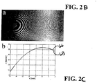
- a delay of 2.18 ps (654 ⁇ m) was introduced between the sample and the reference arms.
- the interference pattern for this setup is shown in Fig. 2B .
- FIG. 2C a measured surface profile along a horizontal line is plotted as a solid line 66 in Fig. 2C .
- FIG. 2C thus illustrates that the profile of the lens (solid line 66) measured using the described system agrees with a calculated profile (dashed line 68).
- the differences between the measured and the calculated profiles can be attributed to the loss of fringe contrast on the right side of the frame and due to low fringe density on the left side.
- the specimen surface is not optically smooth, but contains many surface irregularities.
- the interference between the sample and the reference is manifested by a granular speckle pattern.
- This pattern has a characteristic speckle size that matches the system's point-spread function.
- the coherence length is N times larger, since it is determined only by the spectral width of each spectrally encoded spot.
- the coherence length (310 ⁇ m) was smaller than the confocal parameter (2.7 mm) and therefore determined the axial resolution. The large depth of focus allowed imaging over a range equivalent to the confocal parameter by scanning only the optical path length of the reference arm.
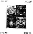
- FIG. 3A The image of the doll's face in Fig. 3A was obtained using white light illumination and a standard CCD camera. It should be noted that the scale bar in FIG. 3A represents 4 mm while the scale bars in FIGs. 3B - 3D represent 1 mm.
- FIG. 3B the standard spectrally encoded-two-dimensional image is shown.
- the surface height, measured by 3D spectrally encoded imaging, is represented as a gray scale image, where z values closer to the probe have a higher pixel intensity.
- This image is obtained by blocking a reference arm in the system of FIG. 2 .
- the light returned from the reference arm was allowed to interfere with that of the sample arm, a speckle pattern was observed in portions of the image.
- a full three-dimensional data set was acquired by capturing 45 frames as the reference arm path length was scanned in steps of 100 ⁇ m.
- FIG. 3D corresponds to a surface rendering of the dolls face using the data shown in Fig. 3C .
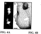
- a sagital (y-z) section was plotted ( Fig. 4A ) from the data.
- the sagital section was placed next to the actual doll's profile ( Fig. 4B ).
- the measurement revealed an axial resolution of approximately 330 ⁇ m (FWHM of the coherence envelope), which is in reasonable agreement with the predicted axial resolution of 310 ⁇ m.
- the scale bar visible in Fig. 4B ) is 1mm.
- Three dimensional (3-D) spectrally-encoded imaging can be used in many configurations to suit specific applications.
- this method is capable of measuring a surface within a volume of 50x50x30 millimeters (x, y, z respectively) with, typically, 200x200x280 resolution points (250 ⁇ m transverse spot-size and 107 ⁇ m axial resolution).
- a CCD camera 10,000 frames per second
- a rapidly scanning optical delay line in the reference arm the three-dimensional data set could be captured and displayed in real time (30 frames per second).
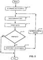
- a technique for producing a three-dimensional image begins by illuminating a line on a sample and then scanning a reference line as shown in processing blocks 70, 72.
- the depth information is determined as shown in block 74. In one embodiment, this is achieved by measuring the number of fringes within a spot on the sample (e.g. analyzing the number of fringes using a fast Fourier Transform(FFT) or other technique) and translating this information to depth information.
- FFT fast Fourier Transform
- the techniques and apparatus described above can be used to provide three-dimensional macroscopic images using a phase-sensitive spectrally encoded imaging technique.
- volume data can be acquired through a single optical fiber without any additional modifications to the spectrally-encoded imaging device.
Claims (36)
- Verfahren zum Erhalten von dreidimensionalen Informationen, die mit mindestens einer Probe (19, 50) zusammenhängen, wobei das Verfahren umfasst:Empfangen von mindestens einer ersten elektromagnetischen Strahlung (14c) von einem Probenarm (18, 42) basierend auf einer quer spektral gestreuten elektromagnetischen Strahlung, die der mindestens einen Probe (19, 50) bereitgestellt wird;wobei die erste elektromagnetische Strahlung (14c) Informationen einschließt, die mindestens einen Anteil der mindestens einen Probe (19, 50) identifizieren;Empfangen von mindestens einer zweiten elektromagnetischen Strahlung (14b) von einem Referenzarm (16, 36);Generieren von ersten Interferenzinformationen basierend auf der ersten und zweiten elektromagnetischen Strahlung (14c, 14b), wobei die ersten Interferenzinformationen aus einer ersten Tiefe (41a') innerhalb der mindestens einen Probe (19, 50) sind, die einer ersten Pfadlänge des Referenzarms (16, 36) entsprechen;Erhalten von mindestens einer relativen Phase zwischen der mindestens einen ersten elektromagnetischen Strahlung (14c), die von der mindestens einen Probe (19, 50) zurückgegeben wird, und der mindestens einen zweiten elektromagnetischen Strahlung (14b), die von dem Referenzarm (16, 36) zurückgegeben wird, um mindestens eine relative Tiefenposition des mindestens einen Anteils zu bestimmen, Ändern des Referenzarms (16, 36) von der ersten Pfadlänge zu einer zweiten Pfadlänge, die sich von der ersten Pfadlänge unterscheidet;Generieren von zweiten Interferenzinformationen, die auf Ändern des Referenzarms (16, 36) von einer ersten Pfadlänge zu der zweiten Pfadlänge basieren,wobei die zweiten Interferenzinformationen von einer zweiten Tiefe (41b') oder einer dritten Tiefe (41c') innerhalb der mindestens einen Probe (19, 50) sind;Bestimmen eines Oberflächenprofils der mindestens einen Probe (19, 50) basierend auf einer Position einer maximalen Speckle-Intensitätsdifferenz zwischen aufeinander folgenden Einzelbildern (Frames) in einer axialen Richtung; undBereitstellen der dreidimensionalen Informationen, die mit der mindestens einen Probe (19, 50) zusammenhängen, als Funktion der ersten Interferenzinformationen, der zweiten Interferenzinformationen und des Oberflächenprofils.
- Verfahren nach Anspruch 1, wobei der Referenzarm (16, 36) von der ersten Pfadlänge auf die zweite Pfadlänge geändert wird, indem eine reflektierende Oberfläche (40) in dem Referenzarm (16, 36) aus einer ersten Position (41a) in entweder eine zweite Position (41b) oder eine dritte Position (41c) bewegt wird.
- Verfahren nach Anspruch 1, wobei mindestens eine von den ersten Interferenzinformationen oder den zweiten Interferenzinformationen generiert wird, indem die erste und zweite elektromagnetische Strahlung (14c, 14b) kombiniert und unter Verwendung einer Streuanordnung (56) quer räumlich gestreut werden.
- Verfahren nach Anspruch 3, ferner umfassend Bereitstellen der gestreuten elektromagnetischen Strahlung an ein Bildgebungssystem (60), um so die dreidimensionalen Informationen zu generieren.
- Verfahren nach Anspruch 4, wobei die gestreute elektromagnetische Strahlung auf einer ladungsgekoppelten Vorrichtung (60) bereitgestellt wird.
- Verfahren nach Anspruch 1, des Weiteren umfassend:spektrales Streuen von mindestens zwei Wellenlängen von mindestens einer speziellen elektromagnetischen Strahlung, die auf dem mindestens einen Anteil der mindestens einen Probe (19, 50) bereitgestellt wird, wobei jede der mindestens zwei Wellenlängen genutzt wird, um mindestens eine jeweilige Querposition von einer Vielzahl von Querpositionen des mindestens einen Anteils zu bestimmen; undBereitstellen der dreidimensionalen Informationen basierend auf jeder von der Vielzahl von Querpositionen und der mindestens einen relativen Tiefenposition.
- Verfahren nach Anspruch 6, ferner umfassend:
Scannen der mindestens einen ersten elektromagnetischen Strahlung (14c) quer über den mindestens einen Anteil der Probe (19, 50) in einer Dimension, um dreidimensionale Daten basierend auf der Vielzahl von Querpositionen zu erhalten. - Verfahren nach Anspruch 6, wobei die Informationen als Funktion der zweidimensionalen Daten bereitgestellt werden.
- Verfahren nach Anspruch 8, wobei die Informationen dreidimensionale Informationen für den mindestens einen Anteil sind, die basierend auf den zweidimensionalen Daten erhalten werden.
- Verfahren nach Anspruch 6, wobei die Informationen dreidimensionale Informationen für den mindestens einen Anteil sind.
- Verfahren nach Anspruch 6, wobei die mindestens eine erste elektromagnetische Strahlung (14c) und die mindestens eine zweite elektromagnetische Strahlung (14b) eine erste Phasenbeziehung haben, und wobei die mindestens eine relative Phase bestimmt wird durch:Detektieren eines ersten Interferenzsignals, das durch eine Interferenz zwischen einer Phase der ersten und zweiten elektromagnetischen Strahlung (14c, 14b) mit der ersten Phasenbeziehung produziert worden ist;Modifizieren einer Phasenlänge der Referenz (40) zu einer zweiten Phasenbeziehung, und Empfangen von mindestens einer dritten elektromagnetischen Strahlung von der Probe (19, 50) und mindestens einer vierten elektromagnetischen Strahlung;Detektieren eines zweiten Interferenzsignals, das durch eine Interferenz zwischen einer Phase der dritten und vierten elektromagnetischen Strahlung mit der zweiten Phasenbeziehung produziert worden ist; undVerarbeiten des ersten und zweiten Interferenzsignals, um Interferenzdaten bereitzustellen.
- Verfahren nach Anspruch 11, wobei die Informationen basierend auf den Interferenzinformationen bereitgestellt werden.
- Verfahren nach Anspruch 12, wobei die Informationen Tiefeninformationen des mindestens einen Anteils einschließen.
- Verfahren nach Anspruch 13, wobei die Tiefeninformationen bestimmt werden, indem das erste Interferenzsignal gemessen wird.
- Verfahren nach Anspruch 14, wobei die Tiefeninformationen ferner bestimmt werden, indem das zweite Interferenzsignal gemessen wird.
- Verfahren nach Anspruch 13, wobei die zweite und vierte elektromagnetische Strahlung unterschiedliche Phasen haben.
- Verfahren nach Anspruch 12, wobei die Informationen Höheninformationen des mindestens einen Anteils an einer Vielzahl von Querpositionen auf dem mindestens einen Anteil einschließen.
- Verfahren nach Anspruch 6, des Weiteren umfassend:
Bewirken von diskreten Änderungen in der Länge eines Pfades (36) der Referenz (40), um die mindestens eine relative Phase zu generieren. - Verfahren nach Anspruch 6, wobei die mindestens eine Querposition eine Vielzahl von Querpositionen ist.
- Verfahren nach Anspruch 6, wobei die mindestens eine Position eine Vielzahl von Positionen einschließt.
- Verfahren nach Anspruch 20, wobei jede der Wellenlängen mit jeweils einer der Positionen zusammenhängt.
- Verfahren nach Anspruch 6, wobei die mindestens eine spezielle elektromagnetische Strahlung auf mindestens zwei separaten jeweiligen Positionen auf der Probe (19, 50) bereitgestellt wird.
- Vorrichtung (10, 30) zum Erhalten von dreidimensionalen Informationen, die mit mindestens einer Probe (19, 50) zusammenhängen, umfassend:mindestens eine erste Anordnung (14, 34), die ausgestaltet ist zum Empfangen von:mindestens einer ersten elektromagnetischen Strahlung (14c) von einem Probenarm (18, 42) basierend auf einer quer spektral gestreuten elektromagnetischen Strahlung, die der mindestens einen Probe (19, 50) bereitgestellt wird;
wobei die erste elektromagnetische Strahlung (14c) Informationen einschließt, die mindestens einen Anteil der mindestens einen Probe (19, 50) identifizieren, undmindestens einer zweiten elektromagnetischen Strahlung (14b) von einem Referenzarm (16, 36);mindestens einer zweiten Anordnung (56), die ausgestaltet ist zum:Generieren von ersten Interferenzinformationen basierend auf der ersten und zweiten elektromagnetischen Strahlung (14c, 14b),
wobei die ersten Interferenzinformationen aus einer ersten Tiefe (41a') innerhalb der mindestens einen Probe (19, 50) sind, die einer ersten Pfadlänge des Referenzarms (16, 36) entsprechen;Erhalten von mindestens einer relativen Phase zwischen der mindestens einen ersten elektromagnetischen Strahlung (14c), die von der mindestens einen Probe (19, 50) zurückgegeben wird, und der mindestens einen zweiten elektromagnetischen Strahlung (14b), die von dem Referenzarm (16, 36) zurückgegeben wird, um mindestens eine relative Tiefenposition des mindestens einen Anteils zu bestimmen; undGenerieren von zweiten Interferenzinformationen basierend darauf, dass der Referenzarm (16, 36) von der ersten Pfadlänge zu einer zweiten Pfadlänge geändert wurde, die sich von der ersten Pfadlänge unterscheidet,
wobei die zweiten Interferenzinformationen von einer zweiten Tiefe (41b') oder einer dritten Tiefe (41c') innerhalb der mindestens einen Probe (19, 50) sind; undmindestens eine dritte Anordnung (20, 60), die ausgestaltet ist zum:Bestimmen eines Oberflächenprofils der mindestens einen Probe (19, 50) basierend auf einer Position einer maximalen Speckle-Intensitätsdifferenz zwischen aufeinander folgenden Frames in einer axialen Richtung; undBereitstellen der dreidimensionalen Informationen, die mit der mindestens einen Probespezies (19, 50) zusammenhängen, als Funktion der ersten Interferenzinformationen, der zweiten Interferenzinformationen und des Oberflächenprofils. - Vorrichtung nach Anspruch 23, ferner umfassend eine Streuanordnung (56), die ausgestaltet ist, um die erste und zweite elektromagnetische Strahlung (14c, 14b) zu kombinieren und quer räumlich zu streuen, um die dreidimensionalen Informationen zu generieren.
- Vorrichtung nach Anspruch 24, ferner umfassen eine ladungsgekoppelte Vorrichtung (60), die ausgestaltet ist, um die gestreute elektromagnetische Strahlung zu empfangen.
- Vorrichtung nach Anspruch 23, ferner umfassend:
mindestens eine weitere Anordnung, die ausgestaltet ist zum:Bereitstellen von mindestens zwei Wellenlängen von mindestens einer speziellen elektromagnetischen Strahlung, die auf dem mindestens einen Anteil der mindestens einen Probe (19, 50) bereitgestellt wird, undBestimmen von mindestens einer jeweiligen Querposition von einer Vielzahl von Querpositionen des mindestens einen Anteils unter Verwendung von jeder der mindestens zwei Wellenlängen,wobei die mindestens eine zweite Anordnung ausgestaltet ist, um die Informationen des Anteils basierend auf der Querposition und der relativen Tiefenposition bereitzustellen. - Vorrichtung nach Anspruch 26, ferner umfassend:
mindestens eine vierte Anordnung, die ausgestaltet ist zum Scannen der mindestens einen ersten elektromagnetischen Strahlung (14c) quer über den mindestens einen Anteil der Probe (19, 50) in einer Dimension, um dreidimensionale Daten basierend auf den Querpositionen zu erhalten. - Vorrichtung nach Anspruch 27, wobei die Informationen als Funktion der zweidimensionalen Daten bereitgestellt werden.
- Vorrichtung nach Anspruch 28, wobei die Informationen dreidimensionale Informationen für den mindestens einen Anteil sind, die basierend auf den zweidimensionalen Daten erhalten werden.
- Vorrichtung nach Anspruch 26, wobei die Informationen dreidimensionale Informationen für den mindestens einen Anteil sind.
- Vorrichtung nach Anspruch 26, ferner umfassend eine Streuanordnung (56), die ausgestaltet ist, um die erste und zweite elektromagnetische Strahlung (14c, 14b) zu kombinieren und quer räumlich zu streuen, um die Informationen zu generieren.
- Vorrichtung nach Anspruch 26, ferner umfassend:
mindestens eine fünfte Anordnung, die ausgestaltet ist, um diskrete Änderungen in der Länge eines Pfades (36) der Referenz (40) zu bewirken, um die mindestens eine relative Phase zu generieren. - Vorrichtung nach Anspruch 26, wobei die mindestens eine Querposition eine Vielzahl von Querpositionen ist.
- Vorrichtung nach Anspruch 26, wobei die mindestens eine Position eine Vielzahl von Positionen einschließt.
- Vorrichtung nach Anspruch 34, wobei jede der Wellenlängen mit jeweils einer von der Vielzahl der Positionen zusammenhängt.
- Vorrichtung nach Anspruch 26, wobei die mindestens eine spezielle elektromagnetische Strahlung auf mindestens zwei separaten jeweiligen Positionen auf der mindestens einen Probe (19, 50) bereitgestellt wird.
Applications Claiming Priority (2)
| Application Number | Priority Date | Filing Date | Title |
|---|---|---|---|
| US52568403P | 2003-11-28 | 2003-11-28 | |
| PCT/US2004/039454 WO2005054780A1 (en) | 2003-11-28 | 2004-11-24 | Method and apparatus for three-dimensional spectrally encoded imaging |
Publications (2)
| Publication Number | Publication Date |
|---|---|
| EP1687587A1 EP1687587A1 (de) | 2006-08-09 |
| EP1687587B1 true EP1687587B1 (de) | 2020-01-08 |
Family
ID=34652372
Family Applications (1)
| Application Number | Title | Priority Date | Filing Date |
|---|---|---|---|
| EP04817883.4A Active EP1687587B1 (de) | 2003-11-28 | 2004-11-24 | Verfahren und vorrichtung für dreidimensionale spektralcodierte bildgebung |
Country Status (4)
| Country | Link |
|---|---|
| US (1) | US7551293B2 (de) |
| EP (1) | EP1687587B1 (de) |
| JP (2) | JP5214883B2 (de) |
| WO (1) | WO2005054780A1 (de) |
Families Citing this family (185)
| Publication number | Priority date | Publication date | Assignee | Title |
|---|---|---|---|---|
| AU2002230842A1 (en) | 2000-10-30 | 2002-05-15 | The General Hospital Corporation | Optical methods and systems for tissue analysis |
| US9295391B1 (en) | 2000-11-10 | 2016-03-29 | The General Hospital Corporation | Spectrally encoded miniature endoscopic imaging probe |
| EP2333523B1 (de) | 2001-04-30 | 2020-04-08 | The General Hospital Corporation | Verfahren und vorrichtung zur verbesserung der bildklarheit und empfindlichkeit bei der optischen kohärenz-tomographie unter verwendung von dynamischer rückkopplung zur kontrolle der fokussierungseigenschaften und der kohärenzsteuerung |
| AT503309B1 (de) | 2001-05-01 | 2011-08-15 | Gen Hospital Corp | Vorrichtung zur bestimmung von atherosklerotischem belag durch messung von optischen gewebeeigenschaften |
| US7355716B2 (en) | 2002-01-24 | 2008-04-08 | The General Hospital Corporation | Apparatus and method for ranging and noise reduction of low coherence interferometry LCI and optical coherence tomography OCT signals by parallel detection of spectral bands |
| EP1426411A1 (de) * | 2002-12-06 | 2004-06-09 | KRATON Polymers Research B.V. | Zusammensetzungen von Styrenblockcopolymeren für die Herstellung transparenter gelfreier Folien |
| US8054468B2 (en) | 2003-01-24 | 2011-11-08 | The General Hospital Corporation | Apparatus and method for ranging and noise reduction of low coherence interferometry LCI and optical coherence tomography OCT signals by parallel detection of spectral bands |
| US7567349B2 (en) | 2003-03-31 | 2009-07-28 | The General Hospital Corporation | Speckle reduction in optical coherence tomography by path length encoded angular compounding |
| JP2006516739A (ja) | 2003-01-24 | 2006-07-06 | ザ・ジェネラル・ホスピタル・コーポレイション | 低コヒーレンス干渉計を用いて組織を識別するためのシステムおよび方法 |
| KR101546024B1 (ko) | 2003-06-06 | 2015-08-20 | 더 제너럴 하스피탈 코포레이션 | 파장 동조 소스용 방법 및 장치 |
| KR101384553B1 (ko) | 2003-10-27 | 2014-04-11 | 더 제너럴 하스피탈 코포레이션 | 주파수 영역 간섭법을 이용하여 광 영상화를 수행하는 방법 및 장치 |
| EP1754016B1 (de) * | 2004-05-29 | 2016-05-18 | The General Hospital Corporation | Prozess, system und softwareanordnung für eine kompensation der chromatischen dispersion unter verwendung reflektierender schichten in der bildgebenden optischen kohärenztopographie (oct) |
| US7447408B2 (en) | 2004-07-02 | 2008-11-04 | The General Hospital Corproation | Imaging system and related techniques |
| KR101332222B1 (ko) | 2004-08-06 | 2013-11-22 | 더 제너럴 하스피탈 코포레이션 | 광간섭 단층촬영법을 이용해서 샘플 내에서 적어도 하나의 위치를 결정하는 방법, 시스템 및 그 방법을 구현하기 위한 소프트웨어가 저장되어 컴퓨터로 판독 가능한 매체 |
| JP5334415B2 (ja) | 2004-08-24 | 2013-11-06 | ザ ジェネラル ホスピタル コーポレイション | 試料の機械的歪み及び弾性的性質を測定するプロセス、システム及びソフトウェア |
| EP2272421A1 (de) | 2004-08-24 | 2011-01-12 | The General Hospital Corporation | Verfahren und Vorrichtung zur Abbildung von Gefäßsegmenten |
| US7365859B2 (en) | 2004-09-10 | 2008-04-29 | The General Hospital Corporation | System and method for optical coherence imaging |
| US7366376B2 (en) | 2004-09-29 | 2008-04-29 | The General Hospital Corporation | System and method for optical coherence imaging |
| EP2278266A3 (de) | 2004-11-24 | 2011-06-29 | The General Hospital Corporation | Interferometer mit gemeinsamem Pfad für endoskopische optische Kohärenztomographie |
| US8922781B2 (en) | 2004-11-29 | 2014-12-30 | The General Hospital Corporation | Arrangements, devices, endoscopes, catheters and methods for performing optical imaging by simultaneously illuminating and detecting multiple points on a sample |
| KR101410867B1 (ko) | 2005-04-28 | 2014-06-23 | 더 제너럴 하스피탈 코포레이션 | 광간섭 정렬 기술로 해부학적 구조와 연계된 정보를평가하는 시스템, 공정 및 소프트웨어 배열 |
| WO2007084175A1 (en) * | 2005-05-04 | 2007-07-26 | University Of Rochester | Interferometric apparatus and method for sizing nanoparticles |
| JP2008542758A (ja) | 2005-05-31 | 2008-11-27 | ザ ジェネラル ホスピタル コーポレイション | スペクトルコード化ヘテロダイン干渉法を画像化に使用可能なシステム、方法、及び装置 |
| EP1889037A2 (de) | 2005-06-01 | 2008-02-20 | The General Hospital Corporation | Vorrichtung, verfahren und system zur abbildung phasenaufgelöster optischer frequenzdomänen |
| DE602006017558D1 (de) | 2005-08-09 | 2010-11-25 | Gen Hospital Corp | Gerät und verfahren zur durchführung von polarisationsbasierter quadraturdemodulation bei optischer kohärenztomographie |
| US8784336B2 (en) | 2005-08-24 | 2014-07-22 | C. R. Bard, Inc. | Stylet apparatuses and methods of manufacture |
| EP1937137B1 (de) | 2005-09-29 | 2022-06-15 | General Hospital Corporation | Verfahren und gerät zur optischen darstellung via spektrale codierung |
| US8205019B2 (en) | 2005-09-30 | 2012-06-19 | Intel Corporation | DMA transfers of sets of data and an exclusive or (XOR) of the sets of data |
| EP1945094B1 (de) | 2005-10-14 | 2018-09-05 | The General Hospital Corporation | Spektral- und frequenz-kodierte fluoreszenz-darstellung |
| JP5680826B2 (ja) * | 2006-01-10 | 2015-03-04 | ザ ジェネラル ホスピタル コーポレイション | 1以上のスペクトルを符号化する内視鏡技術によるデータ生成システム |
| US9087368B2 (en) | 2006-01-19 | 2015-07-21 | The General Hospital Corporation | Methods and systems for optical imaging or epithelial luminal organs by beam scanning thereof |
| US8145018B2 (en) | 2006-01-19 | 2012-03-27 | The General Hospital Corporation | Apparatus for obtaining information for a structure using spectrally-encoded endoscopy techniques and methods for producing one or more optical arrangements |
| US10426548B2 (en) | 2006-02-01 | 2019-10-01 | The General Hosppital Corporation | Methods and systems for providing electromagnetic radiation to at least one portion of a sample using conformal laser therapy procedures |
| EP2659852A3 (de) | 2006-02-01 | 2014-01-15 | The General Hospital Corporation | Vorrichtung zur Anwendung mehrerer elektromagnetischer Strahlungen auf einer Probe |
| WO2007092911A2 (en) | 2006-02-08 | 2007-08-16 | The General Hospital Corporation | Methods, arrangements and systems for obtaining information associated with an anatomical sample using optical microscopy |
| WO2007101026A2 (en) | 2006-02-24 | 2007-09-07 | The General Hospital Corporation | Methods and systems for performing angle-resolved fourier-domain optical coherence tomography |
| US20090323061A1 (en) * | 2006-02-28 | 2009-12-31 | Lukas Novotny | Multi-color hetereodyne interferometric apparatus and method for sizing nanoparticles |
| US7742173B2 (en) | 2006-04-05 | 2010-06-22 | The General Hospital Corporation | Methods, arrangements and systems for polarization-sensitive optical frequency domain imaging of a sample |
| WO2007133961A2 (en) | 2006-05-10 | 2007-11-22 | The General Hospital Corporation | Processes, arrangements and systems for providing frequency domain imaging of a sample |
| WO2007133964A2 (en) | 2006-05-12 | 2007-11-22 | The General Hospital Corporation | Processes, arrangements and systems for providing a fiber layer thickness map based on optical coherence tomography images |
| CN101548153A (zh) * | 2006-05-12 | 2009-09-30 | 西北大学 | 低相干增强背散射光谱的系统、方法和设备 |
| EP2120686A2 (de) * | 2006-06-23 | 2009-11-25 | OPTOPOL Technology Spolka Akcyjna | Gerät für die optische frequenz-domänen-tomographie mit anpasssystem, anpasssystem für ein gerät für die optische frequenz-domänen-tomographie und verfahren zum anpassen des geräts für die optische frequenz-domänen-tomographie und verfahren zur bilddarstellung von objekten |
| EP2054712B1 (de) | 2006-08-25 | 2015-10-07 | The General Hospital Corporation | Vorrichtungen und verfahren zur verstärkung einer optischen kohärenztomographie-abbildung mithilfe volumetrischer filterungsverfahren |
| WO2008049118A2 (en) | 2006-10-19 | 2008-04-24 | The General Hospital Corporation | Apparatus and method for obtaining and providing imaging information associated with at least one portion of a sample and effecting such portion(s) |
| US8388546B2 (en) | 2006-10-23 | 2013-03-05 | Bard Access Systems, Inc. | Method of locating the tip of a central venous catheter |
| US7794407B2 (en) | 2006-10-23 | 2010-09-14 | Bard Access Systems, Inc. | Method of locating the tip of a central venous catheter |
| EP2662674A3 (de) | 2007-01-19 | 2014-06-25 | The General Hospital Corporation | Drehscheibenreflexion zur schnellen Wellenlängendurchstimmung von dispergiertem Breitbandlicht |
| US20080234586A1 (en) * | 2007-03-19 | 2008-09-25 | The General Hospital Corporation | System and method for providing noninvasive diagnosis of compartment syndrome using exemplary laser speckle imaging procedure |
| US9176319B2 (en) | 2007-03-23 | 2015-11-03 | The General Hospital Corporation | Methods, arrangements and apparatus for utilizing a wavelength-swept laser using angular scanning and dispersion procedures |
| US10534129B2 (en) | 2007-03-30 | 2020-01-14 | The General Hospital Corporation | System and method providing intracoronary laser speckle imaging for the detection of vulnerable plaque |
| US8045177B2 (en) | 2007-04-17 | 2011-10-25 | The General Hospital Corporation | Apparatus and methods for measuring vibrations using spectrally-encoded endoscopy |
| US8115919B2 (en) | 2007-05-04 | 2012-02-14 | The General Hospital Corporation | Methods, arrangements and systems for obtaining information associated with a sample using optical microscopy |
| JP5917803B2 (ja) | 2007-07-31 | 2016-05-18 | ザ ジェネラル ホスピタル コーポレイション | 高速ドップラー光周波数領域撮像法のためのビーム走査パターンを放射するシステムおよび方法 |
| US20090062662A1 (en) | 2007-08-27 | 2009-03-05 | Remicalm, Llc | Optical spectroscopic device for the identification of cervical cancer |
| US8040608B2 (en) | 2007-08-31 | 2011-10-18 | The General Hospital Corporation | System and method for self-interference fluorescence microscopy, and computer-accessible medium associated therewith |
| WO2009049296A2 (en) * | 2007-10-12 | 2009-04-16 | The General Hospital Corporation | Systems and processes for optical imaging of luminal anatomic structures |
| US20090099460A1 (en) | 2007-10-16 | 2009-04-16 | Remicalm Llc | Method and device for the optical spectroscopic identification of cervical cancer |
| WO2009059034A1 (en) | 2007-10-30 | 2009-05-07 | The General Hospital Corporation | System and method for cladding mode detection |
| US9649048B2 (en) | 2007-11-26 | 2017-05-16 | C. R. Bard, Inc. | Systems and methods for breaching a sterile field for intravascular placement of a catheter |
| US10751509B2 (en) | 2007-11-26 | 2020-08-25 | C. R. Bard, Inc. | Iconic representations for guidance of an indwelling medical device |
| ES2651898T3 (es) | 2007-11-26 | 2018-01-30 | C.R. Bard Inc. | Sistema integrado para la colocación intravascular de un catéter |
| US9636031B2 (en) | 2007-11-26 | 2017-05-02 | C.R. Bard, Inc. | Stylets for use with apparatus for intravascular placement of a catheter |
| US9456766B2 (en) | 2007-11-26 | 2016-10-04 | C. R. Bard, Inc. | Apparatus for use with needle insertion guidance system |
| US10449330B2 (en) | 2007-11-26 | 2019-10-22 | C. R. Bard, Inc. | Magnetic element-equipped needle assemblies |
| US8849382B2 (en) | 2007-11-26 | 2014-09-30 | C. R. Bard, Inc. | Apparatus and display methods relating to intravascular placement of a catheter |
| US10524691B2 (en) | 2007-11-26 | 2020-01-07 | C. R. Bard, Inc. | Needle assembly including an aligned magnetic element |
| US8781555B2 (en) | 2007-11-26 | 2014-07-15 | C. R. Bard, Inc. | System for placement of a catheter including a signal-generating stylet |
| US9521961B2 (en) | 2007-11-26 | 2016-12-20 | C. R. Bard, Inc. | Systems and methods for guiding a medical instrument |
| US8218152B1 (en) * | 2007-12-04 | 2012-07-10 | The Board Of Trustees Of The University Of Illinois | Group refractive index reconstruction with broadband interferometric confocal microscopy |
| US11123047B2 (en) | 2008-01-28 | 2021-09-21 | The General Hospital Corporation | Hybrid systems and methods for multi-modal acquisition of intravascular imaging data and counteracting the effects of signal absorption in blood |
| US9332942B2 (en) | 2008-01-28 | 2016-05-10 | The General Hospital Corporation | Systems, processes and computer-accessible medium for providing hybrid flourescence and optical coherence tomography imaging |
| US8478382B2 (en) | 2008-02-11 | 2013-07-02 | C. R. Bard, Inc. | Systems and methods for positioning a catheter |
| US10426348B2 (en) | 2008-03-05 | 2019-10-01 | Purdue Research Foundation | Using differential time-frequency tissue-response spectroscopy to evaluate living body response to a drug |
| US8422030B2 (en) * | 2008-03-05 | 2013-04-16 | General Electric Company | Fringe projection system with intensity modulating by columns of a plurality of grating elements |
| US7812968B2 (en) * | 2008-03-05 | 2010-10-12 | Ge Inspection Technologies, Lp | Fringe projection system and method for a probe using a coherent fiber bundle |
| US8725477B2 (en) | 2008-04-10 | 2014-05-13 | Schlumberger Technology Corporation | Method to generate numerical pseudocores using borehole images, digital rock samples, and multi-point statistics |
| EP2263107A4 (de) | 2008-04-10 | 2016-12-28 | Services Petroliers Schlumberger | Verfahren zur charakterisierung einer von einem bohrloch durchquerten geologischen formation |
| US7898656B2 (en) | 2008-04-30 | 2011-03-01 | The General Hospital Corporation | Apparatus and method for cross axis parallel spectroscopy |
| WO2009137701A2 (en) | 2008-05-07 | 2009-11-12 | The General Hospital Corporation | System, method and computer-accessible medium for tracking vessel motion during three-dimensional coronary artery microscopy |
| US8861910B2 (en) | 2008-06-20 | 2014-10-14 | The General Hospital Corporation | Fused fiber optic coupler arrangement and method for use thereof |
| EP2309923B1 (de) | 2008-07-14 | 2020-11-25 | The General Hospital Corporation | Vorrichtung und verfahren für eine farbendoskopie |
| CN103632125A (zh) * | 2008-07-24 | 2014-03-12 | 加利福尼亚大学董事会 | 用于色散型傅立叶变换成像的设备和方法 |
| EP2313143B1 (de) | 2008-08-22 | 2014-09-24 | C.R. Bard, Inc. | Katheteranordnung mit ekg-sensor und magnetischen baugruppen |
| US8437833B2 (en) | 2008-10-07 | 2013-05-07 | Bard Access Systems, Inc. | Percutaneous magnetic gastrostomy |
| US8937724B2 (en) | 2008-12-10 | 2015-01-20 | The General Hospital Corporation | Systems and methods for extending imaging depth range of optical coherence tomography through optical sub-sampling |
| WO2010090837A2 (en) | 2009-01-20 | 2010-08-12 | The General Hospital Corporation | Endoscopic biopsy apparatus, system and method |
| EP2382456A4 (de) | 2009-01-26 | 2012-07-25 | Gen Hospital Corp | System, verfahren und computermedium für mikroskopie mit weitem feld und sehr hoher auflösung |
| JP6053284B2 (ja) | 2009-02-04 | 2016-12-27 | ザ ジェネラル ホスピタル コーポレイション | ハイスピード光学波長チューニング源の利用のための装置及び方法 |
| US9351642B2 (en) | 2009-03-12 | 2016-05-31 | The General Hospital Corporation | Non-contact optical system, computer-accessible medium and method for measurement at least one mechanical property of tissue using coherent speckle technique(s) |
| US8311788B2 (en) | 2009-07-01 | 2012-11-13 | Schlumberger Technology Corporation | Method to quantify discrete pore shapes, volumes, and surface areas using confocal profilometry |
| US9532724B2 (en) | 2009-06-12 | 2017-01-03 | Bard Access Systems, Inc. | Apparatus and method for catheter navigation using endovascular energy mapping |
| ES2745861T3 (es) | 2009-06-12 | 2020-03-03 | Bard Access Systems Inc | Aparato, algoritmo de procesamiento de datos asistido por ordenador y medio de almacenamiento informático para posicionar un dispositivo endovascular en o cerca del corazón |
| JP5819823B2 (ja) | 2009-07-14 | 2015-11-24 | ザ ジェネラル ホスピタル コーポレイション | 血管の内部の流れおよび圧力を測定する装置および装置の作動方法 |
| EP2464407A4 (de) | 2009-08-10 | 2014-04-02 | Bard Access Systems Inc | Vorrichtungen und verfahren für endovaskuläre elektrographie |
| US11103213B2 (en) | 2009-10-08 | 2021-08-31 | C. R. Bard, Inc. | Spacers for use with an ultrasound probe |
| US20150285728A1 (en) | 2009-12-11 | 2015-10-08 | Washington University | Detection of nano-scale particles with a self-referenced and self-heterodyned raman micro-laser |
| US8704155B2 (en) * | 2009-12-11 | 2014-04-22 | Washington University | Nanoscale object detection using a whispering gallery mode resonator |
| US9012830B2 (en) * | 2009-12-11 | 2015-04-21 | Washington University | Systems and methods for particle detection |
| US11754488B2 (en) | 2009-12-11 | 2023-09-12 | Washington University | Opto-mechanical system and method having chaos induced stochastic resonance and opto-mechanically mediated chaos transfer |
| US8792105B2 (en) * | 2010-01-19 | 2014-07-29 | Si-Ware Systems | Interferometer with variable optical path length reference mirror using overlapping depth scan signals |
| JP2013518676A (ja) | 2010-02-02 | 2013-05-23 | シー・アール・バード・インコーポレーテッド | カテーテルナビゲーションおよびチップの位置を特定するための装置および方法 |
| EP2542145B1 (de) | 2010-03-05 | 2020-08-12 | The General Hospital Corporation | Systeme zur bereitstellung mikroskopischer bilder von mindestens einer anatomischen struktur mit einer bestimmten auflösung |
| CN101799280B (zh) * | 2010-03-24 | 2012-05-09 | 上海应用技术学院 | 基于光纤二维组合编码结构的混频莫尔图像生成方法 |
| US9069130B2 (en) | 2010-05-03 | 2015-06-30 | The General Hospital Corporation | Apparatus, method and system for generating optical radiation from biological gain media |
| WO2011149972A2 (en) | 2010-05-25 | 2011-12-01 | The General Hospital Corporation | Systems, devices, methods, apparatus and computer-accessible media for providing optical imaging of structures and compositions |
| WO2011150069A2 (en) * | 2010-05-25 | 2011-12-01 | The General Hospital Corporation | Apparatus, systems, methods and computer-accessible medium for spectral analysis of optical coherence tomography images |
| CN103037762B (zh) | 2010-05-28 | 2016-07-13 | C·R·巴德股份有限公司 | 用于与针插入引导系统一起使用的装置 |
| US10285568B2 (en) | 2010-06-03 | 2019-05-14 | The General Hospital Corporation | Apparatus and method for devices for imaging structures in or at one or more luminal organs |
| US9977859B2 (en) * | 2010-06-17 | 2018-05-22 | Purdue Reserach Foundation | Digital holographic method of measuring cellular activity and of using results to screen compounds |
| US10401793B2 (en) | 2010-06-17 | 2019-09-03 | Purdue Research Foundation | Digital holographic method of measuring cellular activity and measuring apparatus with improved stability |
| CA2806353A1 (en) | 2010-08-09 | 2012-02-16 | C.R. Bard Inc. | Support and cover structures for an ultrasound probe head |
| MX338127B (es) | 2010-08-20 | 2016-04-04 | Bard Inc C R | Reconfirmacion de colocacion de una punta de cateter asistida por ecg. |
| US9510758B2 (en) | 2010-10-27 | 2016-12-06 | The General Hospital Corporation | Apparatus, systems and methods for measuring blood pressure within at least one vessel |
| CN103189009B (zh) | 2010-10-29 | 2016-09-07 | C·R·巴德股份有限公司 | 医疗设备的生物阻抗辅助放置 |
| US8982355B2 (en) * | 2010-12-09 | 2015-03-17 | The United States Of America As Represented By The Administrator Of The National Aeronautics And Space Administration | Smart optical material characterization system and method |
| JP5977763B2 (ja) * | 2011-02-18 | 2016-08-24 | ザ ジェネラル ホスピタル コーポレイション | 生体組織の機械的性質を測定するためのレーザースペックルマイクロレオメーター |
| US10359361B2 (en) * | 2011-02-18 | 2019-07-23 | The General Hospital Corporation | Laser speckle micro-rheology in characterization of biomechanical properties of tissues |
| US10586341B2 (en) | 2011-03-04 | 2020-03-10 | General Electric Company | Method and device for measuring features on or near an object |
| US10019812B2 (en) | 2011-03-04 | 2018-07-10 | General Electric Company | Graphic overlay for measuring dimensions of features using a video inspection device |
| US9875574B2 (en) | 2013-12-17 | 2018-01-23 | General Electric Company | Method and device for automatically identifying the deepest point on the surface of an anomaly |
| US9984474B2 (en) | 2011-03-04 | 2018-05-29 | General Electric Company | Method and device for measuring features on or near an object |
| US10157495B2 (en) | 2011-03-04 | 2018-12-18 | General Electric Company | Method and device for displaying a two-dimensional image of a viewed object simultaneously with an image depicting the three-dimensional geometry of the viewed object |
| WO2012149175A1 (en) | 2011-04-29 | 2012-11-01 | The General Hospital Corporation | Means for determining depth-resolved physical and/or optical properties of scattering media |
| EP2721698B1 (de) * | 2011-06-17 | 2019-01-02 | I-Property Holding Corp. | 3d-laserbeschriftung in glas |
| AU2012278809B2 (en) | 2011-07-06 | 2016-09-29 | C.R. Bard, Inc. | Needle length determination and calibration for insertion guidance system |
| WO2013013049A1 (en) | 2011-07-19 | 2013-01-24 | The General Hospital Corporation | Systems, methods, apparatus and computer-accessible-medium for providing polarization-mode dispersion compensation in optical coherence tomography |
| USD724745S1 (en) | 2011-08-09 | 2015-03-17 | C. R. Bard, Inc. | Cap for an ultrasound probe |
| USD699359S1 (en) | 2011-08-09 | 2014-02-11 | C. R. Bard, Inc. | Ultrasound probe head |
| EP3835718B1 (de) | 2011-08-25 | 2023-07-26 | The General Hospital Corporation | Vorrichtung zur bereitstellung mikrooptischer kohärenztomographie in einem atmungssystem |
| WO2013066631A1 (en) | 2011-10-18 | 2013-05-10 | The General Hospital Corporation | Apparatus and methods for producing and/or providing recirculating optical delay(s) |
| WO2013070775A1 (en) | 2011-11-07 | 2013-05-16 | C.R. Bard, Inc | Ruggedized ultrasound hydrogel insert |
| WO2013148306A1 (en) | 2012-03-30 | 2013-10-03 | The General Hospital Corporation | Imaging system, method and distal attachment for multidirectional field of view endoscopy |
| US11490797B2 (en) | 2012-05-21 | 2022-11-08 | The General Hospital Corporation | Apparatus, device and method for capsule microscopy |
| WO2013188833A2 (en) | 2012-06-15 | 2013-12-19 | C.R. Bard, Inc. | Apparatus and methods for detection of a removable cap on an ultrasound probe |
| JP6227652B2 (ja) | 2012-08-22 | 2017-11-08 | ザ ジェネラル ホスピタル コーポレイション | ソフトリソグラフィを用いてミニチュア内視鏡を製作するためのシステム、方法、およびコンピュータ・アクセス可能媒体 |
| GB2508874B (en) * | 2012-12-13 | 2017-09-20 | Univ Of Huddersfield | Interferometric apparatus and sample characteristic determining apparatus using such apparatus |
| JP6560126B2 (ja) | 2013-01-28 | 2019-08-14 | ザ ジェネラル ホスピタル コーポレイション | 光周波数ドメインイメージングに重ね合わせされる拡散分光法を提供するための装置および方法 |
| US10893806B2 (en) | 2013-01-29 | 2021-01-19 | The General Hospital Corporation | Apparatus, systems and methods for providing information regarding the aortic valve |
| WO2014121082A1 (en) | 2013-02-01 | 2014-08-07 | The General Hospital Corporation | Objective lens arrangement for confocal endomicroscopy |
| US9335154B2 (en) * | 2013-02-01 | 2016-05-10 | Duke University | Systems and methods of angle-resolved low coherence interferometry based optical correlation |
| SG11201505637XA (en) | 2013-03-07 | 2015-08-28 | Univ Nanyang Tech | Optical imaging device and method for imaging a sample |
| EP2968000B1 (de) | 2013-03-13 | 2018-08-15 | Optimedica Corporation | Augenchirurgisches lasersystem |
| WO2014163897A1 (en) | 2013-03-13 | 2014-10-09 | Optimedica Corporation | Free floating patient interface for laser surgery system |
| JP6378311B2 (ja) | 2013-03-15 | 2018-08-22 | ザ ジェネラル ホスピタル コーポレイション | 物体を特徴付ける方法とシステム |
| WO2014186353A1 (en) | 2013-05-13 | 2014-11-20 | The General Hospital Corporation | Detecting self-interefering fluorescence phase and amplitude |
| EP3021735A4 (de) | 2013-07-19 | 2017-04-19 | The General Hospital Corporation | Bestimmung der augenbewegung mittels netzhautabbildung mit rückkopplung |
| EP4349242A2 (de) | 2013-07-19 | 2024-04-10 | The General Hospital Corporation | Bildgebungsvorrichtung und verfahren mit multidirektionaler sichtfeldendoskopie |
| WO2015013651A2 (en) | 2013-07-26 | 2015-01-29 | The General Hospital Corporation | System, apparatus and method utilizing optical dispersion for fourier-domain optical coherence tomography |
| US9835436B2 (en) * | 2013-11-01 | 2017-12-05 | Tomey Corporation | Wavelength encoded multi-beam optical coherence tomography |
| US9818039B2 (en) | 2013-12-17 | 2017-11-14 | General Electric Company | Method and device for automatically identifying a point of interest in a depth measurement on a viewed object |
| US9842430B2 (en) | 2013-12-17 | 2017-12-12 | General Electric Company | Method and device for automatically identifying a point of interest on a viewed object |
| US9538926B2 (en) * | 2013-12-26 | 2017-01-10 | Fundacio Institut De Ciencies Fotoniques | Speckle contrast optical tomography |
| US9733460B2 (en) | 2014-01-08 | 2017-08-15 | The General Hospital Corporation | Method and apparatus for microscopic imaging |
| US20160338578A1 (en) * | 2014-01-17 | 2016-11-24 | The General Hospital Corporation | Method and apparatus for acquisition of volumetric imaging data within an anatomic structure |
| US10095020B2 (en) | 2014-01-31 | 2018-10-09 | Canon U.S.A., Inc. | Apparatus and methods for color endoscopy |
| US10736494B2 (en) | 2014-01-31 | 2020-08-11 | The General Hospital Corporation | System and method for facilitating manual and/or automatic volumetric imaging with real-time tension or force feedback using a tethered imaging device |
| ES2811323T3 (es) | 2014-02-06 | 2021-03-11 | Bard Inc C R | Sistemas para el guiado y la colocación de un dispositivo intravascular |
| US10228556B2 (en) | 2014-04-04 | 2019-03-12 | The General Hospital Corporation | Apparatus and method for controlling propagation and/or transmission of electromagnetic radiation in flexible waveguide(s) |
| KR102513779B1 (ko) | 2014-07-25 | 2023-03-24 | 더 제너럴 하스피탈 코포레이션 | 생체 내 이미징 및 진단을 위한 장치, 디바이스 및 방법 |
| KR101658982B1 (ko) * | 2014-11-13 | 2016-09-26 | 주식회사 고영테크놀러지 | 회절 격자를 이용한 3차원 형상 측정 장치 |
| US10973584B2 (en) | 2015-01-19 | 2021-04-13 | Bard Access Systems, Inc. | Device and method for vascular access |
| ES2913531T3 (es) | 2015-04-16 | 2022-06-02 | Gentuity Llc | Sondas microópticas para neurología |
| US10349890B2 (en) | 2015-06-26 | 2019-07-16 | C. R. Bard, Inc. | Connector interface for ECG-based catheter positioning system |
| US10194065B2 (en) | 2015-08-05 | 2019-01-29 | Canon U.S.A., Inc. | Endoscope probes and systems, and methods for use therewith |
| WO2017040484A1 (en) | 2015-08-31 | 2017-03-09 | Gentuity, Llc | Imaging system includes imaging probe and delivery devices |
| US11000207B2 (en) | 2016-01-29 | 2021-05-11 | C. R. Bard, Inc. | Multiple coil system for tracking a medical device |
| US11150173B2 (en) | 2016-02-12 | 2021-10-19 | The General Hospital Corporation | Laser speckle micro-rheology in characterization of biomechanical properties of tissues |
| US10401610B2 (en) | 2016-07-15 | 2019-09-03 | Canon Usa, Inc. | Spectrally encoded probe with multiple diffraction orders |
| WO2018057924A1 (en) | 2016-09-23 | 2018-03-29 | Canon U.S.A. Inc. | Spectrally encoded endoscopy apparatus and methods |
| US10898068B2 (en) | 2016-11-01 | 2021-01-26 | Canon U.S.A., Inc. | Multi-bandwidth spectrally encoded endoscope |
| WO2018132490A1 (en) | 2017-01-12 | 2018-07-19 | Canon U.S.A., Inc. | Spectrally encoded forward view endoscope and spectrally encoded multi-view endoscope, probe, and imaging apparatus |
| US10895692B2 (en) | 2017-06-01 | 2021-01-19 | Canon U.S.A., Inc. | Fiber optic rotary joints and methods of using and manufacturing same |
| DE102017115922C5 (de) * | 2017-07-14 | 2023-03-23 | Precitec Gmbh & Co. Kg | Verfahren und Vorrichtung zur Messung und Einstellung eines Abstands zwischen einem Bearbeitungskopf und einem Werkstück sowie dazugehöriges Verfahren zur Regelung |
| US10825152B2 (en) | 2017-09-14 | 2020-11-03 | Canon U.S.A., Inc. | Distortion measurement and correction for spectrally encoded endoscopy |
| US10357160B2 (en) | 2017-10-05 | 2019-07-23 | Canon U.S.A., Inc. | Image acquiring apparatus, systems, and methods |
| KR101891036B1 (ko) | 2017-10-19 | 2018-08-23 | 한국기초과학지원연구원 | 고속 병렬 광간섭 단층 이미지 생성 장치 및 방법 |
| US11224336B2 (en) | 2017-11-17 | 2022-01-18 | Canon U.S.A., Inc. | Rotational extender and/or repeater for rotating fiber based optical imaging systems, and methods and storage mediums for use therewith |
| US10809538B2 (en) | 2017-11-27 | 2020-10-20 | Canon U.S.A., Inc. | Image acquisition apparatus, spectral apparatus, methods, and storage medium for use with same |
| JP7160935B2 (ja) | 2017-11-28 | 2022-10-25 | ジェンテュイティ・リミテッド・ライアビリティ・カンパニー | 撮像システム |
| TWI699559B (zh) * | 2018-01-16 | 2020-07-21 | 美商伊路米納有限公司 | 結構照明成像系統和使用結構化光來創建高解析度圖像的方法 |
| US10506922B2 (en) | 2018-04-06 | 2019-12-17 | Canon U.S.A., Inc. | Spectrometer for color spectrally-encoded endoscopy |
| EP3852622A1 (de) | 2018-10-16 | 2021-07-28 | Bard Access Systems, Inc. | Sicherheitsausgerüstete verbindungssysteme und verfahren dafür zur herstellung von elektrischen verbindungen |
| GB201819029D0 (en) * | 2018-11-22 | 2019-01-09 | Cambridge Entpr Ltd | Optical microscopy |
| US20200240769A1 (en) * | 2019-01-25 | 2020-07-30 | Cam4D Ltd. | Depth and spectral measurement with wavelength-encoded light pattern |
| US11707186B2 (en) | 2019-06-14 | 2023-07-25 | Canon U.S.A., Inc. | Fluorescence or auto-fluorescence trigger or triggers |
Family Cites Families (149)
| Publication number | Priority date | Publication date | Assignee | Title |
|---|---|---|---|---|
| US2339754A (en) * | 1941-03-04 | 1944-01-25 | Westinghouse Electric & Mfg Co | Supervisory apparatus |
| US3601480A (en) * | 1968-07-10 | 1971-08-24 | Physics Int Co | Optical tunnel high-speed camera system |
| JPS4932484U (de) | 1972-06-19 | 1974-03-20 | ||
| FR2253410A5 (de) * | 1973-12-03 | 1975-06-27 | Inst Nat Sante Rech Med | |
| US3941121A (en) * | 1974-12-20 | 1976-03-02 | The University Of Cincinnati | Focusing fiber-optic needle endoscope |
| US3983507A (en) | 1975-01-06 | 1976-09-28 | Research Corporation | Tunable laser systems and method |
| US3973219A (en) | 1975-04-24 | 1976-08-03 | Cornell Research Foundation, Inc. | Very rapidly tuned cw dye laser |
| US4141362A (en) * | 1977-05-23 | 1979-02-27 | Richard Wolf Gmbh | Laser endoscope |
| FR2448728A1 (fr) | 1979-02-07 | 1980-09-05 | Thomson Csf | Dispositif joint tournant pour liaison par conducteurs optiques et systeme comportant un tel dispositif |
| US4295738A (en) | 1979-08-30 | 1981-10-20 | United Technologies Corporation | Fiber optic strain sensor |
| US4300816A (en) | 1979-08-30 | 1981-11-17 | United Technologies Corporation | Wide band multicore optical fiber |
| US4428643A (en) | 1981-04-08 | 1984-01-31 | Xerox Corporation | Optical scanning system with wavelength shift correction |
| US5065331A (en) | 1981-05-18 | 1991-11-12 | Vachon Reginald I | Apparatus and method for determining the stress and strain in pipes, pressure vessels, structural members and other deformable bodies |
| GB2106736B (en) | 1981-09-03 | 1985-06-12 | Standard Telephones Cables Ltd | Optical transmission system |
| US4479499A (en) | 1982-01-29 | 1984-10-30 | Alfano Robert R | Method and apparatus for detecting the presence of caries in teeth using visible light |
| US4601036A (en) * | 1982-09-30 | 1986-07-15 | Honeywell Inc. | Rapidly tunable laser |
| CH663466A5 (fr) * | 1983-09-12 | 1987-12-15 | Battelle Memorial Institute | Procede et dispositif pour determiner la position d'un objet par rapport a une reference. |
| US4607622A (en) * | 1985-04-11 | 1986-08-26 | Charles D. Fritch | Fiber optic ocular endoscope |
| US4631498A (en) | 1985-04-26 | 1986-12-23 | Hewlett-Packard Company | CW Laser wavemeter/frequency locking technique |
| US5040889A (en) | 1986-05-30 | 1991-08-20 | Pacific Scientific Company | Spectrometer with combined visible and ultraviolet sample illumination |
| US4770492A (en) | 1986-10-28 | 1988-09-13 | Spectran Corporation | Pressure or strain sensitive optical fiber |
| US4892406A (en) | 1988-01-11 | 1990-01-09 | United Technologies Corporation | Method of and arrangement for measuring vibrations |
| FR2626367B1 (fr) * | 1988-01-25 | 1990-05-11 | Thomson Csf | Capteur de temperature multipoints a fibre optique |
| FR2626383B1 (fr) | 1988-01-27 | 1991-10-25 | Commissariat Energie Atomique | Procede de microscopie optique confocale a balayage et en profondeur de champ etendue et dispositifs pour la mise en oeuvre du procede |
| US4925302A (en) | 1988-04-13 | 1990-05-15 | Hewlett-Packard Company | Frequency locking device |
| ATE158659T1 (de) * | 1988-07-13 | 1997-10-15 | Optiscan Pty Ltd | Confokales abtast-endoskop |
| GB8817672D0 (en) | 1988-07-25 | 1988-09-01 | Sira Ltd | Optical apparatus |
| US4868834A (en) | 1988-09-14 | 1989-09-19 | The United States Of America As Represented By The Secretary Of The Army | System for rapidly tuning a low pressure pulsed laser |
| DE3833602A1 (de) * | 1988-10-03 | 1990-02-15 | Krupp Gmbh | Spektrometer zur gleichzeitigen intensitaetsmessung in verschiedenen spektralbereichen |
| WO1990006718A1 (en) * | 1988-12-21 | 1990-06-28 | Massachusetts Institute Of Technology | A method for laser induced fluorescence of tissue |
| US5046501A (en) | 1989-01-18 | 1991-09-10 | Wayne State University | Atherosclerotic identification |
| US5317389A (en) * | 1989-06-12 | 1994-05-31 | California Institute Of Technology | Method and apparatus for white-light dispersed-fringe interferometric measurement of corneal topography |
| US4965599A (en) | 1989-11-13 | 1990-10-23 | Eastman Kodak Company | Scanning apparatus for halftone image screen writing |
| US5039193A (en) * | 1990-04-03 | 1991-08-13 | Focal Technologies Incorporated | Fibre optic single mode rotary joint |
| US5262644A (en) | 1990-06-29 | 1993-11-16 | Southwest Research Institute | Remote spectroscopy for raman and brillouin scattering |
| US5197470A (en) * | 1990-07-16 | 1993-03-30 | Eastman Kodak Company | Near infrared diagnostic method and instrument |
| GB9015793D0 (en) * | 1990-07-18 | 1990-09-05 | Medical Res Council | Confocal scanning optical microscope |
| US5127730A (en) * | 1990-08-10 | 1992-07-07 | Regents Of The University Of Minnesota | Multi-color laser scanning confocal imaging system |
| US5305759A (en) * | 1990-09-26 | 1994-04-26 | Olympus Optical Co., Ltd. | Examined body interior information observing apparatus by using photo-pulses controlling gains for depths |
| US5202745A (en) * | 1990-11-07 | 1993-04-13 | Hewlett-Packard Company | Polarization independent optical coherence-domain reflectometry |
| JP3035336B2 (ja) * | 1990-11-27 | 2000-04-24 | 興和株式会社 | 血流測定装置 |
| US5228001A (en) | 1991-01-23 | 1993-07-13 | Syracuse University | Optical random access memory |
| US6198532B1 (en) * | 1991-02-22 | 2001-03-06 | Applied Spectral Imaging Ltd. | Spectral bio-imaging of the eye |
| US5293872A (en) * | 1991-04-03 | 1994-03-15 | Alfano Robert R | Method for distinguishing between calcified atherosclerotic tissue and fibrous atherosclerotic tissue or normal cardiovascular tissue using Raman spectroscopy |
| US6564087B1 (en) * | 1991-04-29 | 2003-05-13 | Massachusetts Institute Of Technology | Fiber optic needle probes for optical coherence tomography imaging |
| US5465147A (en) * | 1991-04-29 | 1995-11-07 | Massachusetts Institute Of Technology | Method and apparatus for acquiring images using a ccd detector array and no transverse scanner |
| US6111645A (en) * | 1991-04-29 | 2000-08-29 | Massachusetts Institute Of Technology | Grating based phase control optical delay line |
| US5748598A (en) * | 1995-12-22 | 1998-05-05 | Massachusetts Institute Of Technology | Apparatus and methods for reading multilayer storage media using short coherence length sources |
| DE69227902T3 (de) | 1991-04-29 | 2010-04-22 | Massachusetts Institute Of Technology, Cambridge | Vorrichtung für optische abbildung und messung |
| US5441053A (en) | 1991-05-03 | 1995-08-15 | University Of Kentucky Research Foundation | Apparatus and method for multiple wavelength of tissue |
| DE4128744C1 (de) * | 1991-08-29 | 1993-04-22 | Siemens Ag, 8000 Muenchen, De | |
| US5353790A (en) | 1992-01-17 | 1994-10-11 | Board Of Regents, The University Of Texas System | Method and apparatus for optical measurement of bilirubin in tissue |
| US5248876A (en) | 1992-04-21 | 1993-09-28 | International Business Machines Corporation | Tandem linear scanning confocal imaging system with focal volumes at different heights |
| US5486701A (en) * | 1992-06-16 | 1996-01-23 | Prometrix Corporation | Method and apparatus for measuring reflectance in two wavelength bands to enable determination of thin film thickness |
| US5716324A (en) | 1992-08-25 | 1998-02-10 | Fuji Photo Film Co., Ltd. | Endoscope with surface and deep portion imaging systems |
| US5772597A (en) | 1992-09-14 | 1998-06-30 | Sextant Medical Corporation | Surgical tool end effector |
| US5698397A (en) | 1995-06-07 | 1997-12-16 | Sri International | Up-converting reporters for biological and other assays using laser excitation techniques |
| US5439000A (en) | 1992-11-18 | 1995-08-08 | Spectrascience, Inc. | Method of diagnosing tissue with guidewire |
| US5383467A (en) * | 1992-11-18 | 1995-01-24 | Spectrascience, Inc. | Guidewire catheter and apparatus for diagnostic imaging |
| DE4310209C2 (de) * | 1993-03-29 | 1996-05-30 | Bruker Medizintech | Optische stationäre Bildgebung in stark streuenden Medien |
| DE4314189C1 (de) | 1993-04-30 | 1994-11-03 | Bodenseewerk Geraetetech | Vorrichtung zur Untersuchung von Lichtleitfasern aus Glas mittels Heterodyn-Brillouin-Spektroskopie |
| US5454807A (en) | 1993-05-14 | 1995-10-03 | Boston Scientific Corporation | Medical treatment of deeply seated tissue using optical radiation |
| EP0627643B1 (de) | 1993-06-03 | 1999-05-06 | Hamamatsu Photonics K.K. | Optisches Laser-Abtastsystem mit Axikon |
| US5803082A (en) | 1993-11-09 | 1998-09-08 | Staplevision Inc. | Omnispectramammography |
| US5450203A (en) | 1993-12-22 | 1995-09-12 | Electroglas, Inc. | Method and apparatus for determining an objects position, topography and for imaging |
| US5411016A (en) * | 1994-02-22 | 1995-05-02 | Scimed Life Systems, Inc. | Intravascular balloon catheter for use in combination with an angioscope |
| US5590660A (en) * | 1994-03-28 | 1997-01-07 | Xillix Technologies Corp. | Apparatus and method for imaging diseased tissue using integrated autofluorescence |
| DE4411017C2 (de) * | 1994-03-30 | 1995-06-08 | Alexander Dr Knuettel | Optische stationäre spektroskopische Bildgebung in stark streuenden Objekten durch spezielle Lichtfokussierung und Signal-Detektion von Licht unterschiedlicher Wellenlängen |
| TW275570B (de) * | 1994-05-05 | 1996-05-11 | Boehringer Mannheim Gmbh | |
| US5459325A (en) | 1994-07-19 | 1995-10-17 | Molecular Dynamics, Inc. | High-speed fluorescence scanner |
| US5491524A (en) * | 1994-10-05 | 1996-02-13 | Carl Zeiss, Inc. | Optical coherence tomography corneal mapping apparatus |
| US5740808A (en) * | 1996-10-28 | 1998-04-21 | Ep Technologies, Inc | Systems and methods for guilding diagnostic or therapeutic devices in interior tissue regions |
| US5817144A (en) | 1994-10-25 | 1998-10-06 | Latis, Inc. | Method for contemporaneous application OF laser energy and localized pharmacologic therapy |
| US6033721A (en) * | 1994-10-26 | 2000-03-07 | Revise, Inc. | Image-based three-axis positioner for laser direct write microchemical reaction |
| US5600486A (en) * | 1995-01-30 | 1997-02-04 | Lockheed Missiles And Space Company, Inc. | Color separation microlens |
| RU2100787C1 (ru) * | 1995-03-01 | 1997-12-27 | Геликонов Валентин Михайлович | Оптоволоконный интерферометр и оптоволоконный пьезоэлектрический преобразователь |
| US5526338A (en) | 1995-03-10 | 1996-06-11 | Yeda Research & Development Co. Ltd. | Method and apparatus for storage and retrieval with multilayer optical disks |
| US5697373A (en) | 1995-03-14 | 1997-12-16 | Board Of Regents, The University Of Texas System | Optical method and apparatus for the diagnosis of cervical precancers using raman and fluorescence spectroscopies |
| US5735276A (en) * | 1995-03-21 | 1998-04-07 | Lemelson; Jerome | Method and apparatus for scanning and evaluating matter |
| US5621830A (en) * | 1995-06-07 | 1997-04-15 | Smith & Nephew Dyonics Inc. | Rotatable fiber optic joint |
| US5785651A (en) | 1995-06-07 | 1998-07-28 | Keravision, Inc. | Distance measuring confocal microscope |
| WO1997001167A1 (en) * | 1995-06-21 | 1997-01-09 | Massachusetts Institute Of Technology | Apparatus and method for accessing data on multilayered optical media |
| ATA107495A (de) | 1995-06-23 | 1996-06-15 | Fercher Adolf Friedrich Dr | Kohärenz-biometrie und -tomographie mit dynamischem kohärentem fokus |
| AU1130797A (en) * | 1995-08-24 | 1997-03-19 | Purdue Research Foundation | Fluorescence lifetime-based imaging and spectroscopy in tissues and other random media |
| US5719399A (en) * | 1995-12-18 | 1998-02-17 | The Research Foundation Of City College Of New York | Imaging and characterization of tissue based upon the preservation of polarized light transmitted therethrough |
| US5840023A (en) | 1996-01-31 | 1998-11-24 | Oraevsky; Alexander A. | Optoacoustic imaging for medical diagnosis |
| US5862273A (en) * | 1996-02-23 | 1999-01-19 | Kaiser Optical Systems, Inc. | Fiber optic probe with integral optical filtering |
| US5843000A (en) | 1996-05-07 | 1998-12-01 | The General Hospital Corporation | Optical biopsy forceps and method of diagnosing tissue |
| ATA84696A (de) | 1996-05-14 | 1998-03-15 | Adolf Friedrich Dr Fercher | Verfahren und anordnungen zur kontrastanhebung in der optischen kohärenztomographie |
| US5795295A (en) | 1996-06-25 | 1998-08-18 | Carl Zeiss, Inc. | OCT-assisted surgical microscope with multi-coordinate manipulator |
| US5842995A (en) | 1996-06-28 | 1998-12-01 | Board Of Regents, The Univerisity Of Texas System | Spectroscopic probe for in vivo measurement of raman signals |
| US5840075A (en) | 1996-08-23 | 1998-11-24 | Eclipse Surgical Technologies, Inc. | Dual laser device for transmyocardial revascularization procedures |
| US6249349B1 (en) * | 1996-09-27 | 2001-06-19 | Vincent Lauer | Microscope generating a three-dimensional representation of an object |
| DE19640495C2 (de) * | 1996-10-01 | 1999-12-16 | Leica Microsystems | Vorrichtung zur konfokalen Oberflächenvermessung |
| US5843052A (en) | 1996-10-04 | 1998-12-01 | Benja-Athon; Anuthep | Irrigation kit for application of fluids and chemicals for cleansing and sterilizing wounds |
| US6044288A (en) * | 1996-11-08 | 2000-03-28 | Imaging Diagnostics Systems, Inc. | Apparatus and method for determining the perimeter of the surface of an object being scanned |
| US5872879A (en) * | 1996-11-25 | 1999-02-16 | Boston Scientific Corporation | Rotatable connecting optical fibers |
| US5871449A (en) * | 1996-12-27 | 1999-02-16 | Brown; David Lloyd | Device and method for locating inflamed plaque in an artery |
| US5760901A (en) * | 1997-01-28 | 1998-06-02 | Zetetic Institute | Method and apparatus for confocal interference microscopy with background amplitude reduction and compensation |
| US5801826A (en) | 1997-02-18 | 1998-09-01 | Williams Family Trust B | Spectrometric device and method for recognizing atomic and molecular signatures |
| US6010449A (en) * | 1997-02-28 | 2000-01-04 | Lumend, Inc. | Intravascular catheter system for treating a vascular occlusion |
| AU6604998A (en) * | 1997-03-13 | 1998-09-29 | Biomax Technologies, Inc. | Methods and apparatus for detecting the rejection of transplanted tissue |
| US5887009A (en) * | 1997-05-22 | 1999-03-23 | Optical Biopsy Technologies, Inc. | Confocal optical scanning system employing a fiber laser |
| US6006128A (en) * | 1997-06-02 | 1999-12-21 | Izatt; Joseph A. | Doppler flow imaging using optical coherence tomography |
| US6208415B1 (en) * | 1997-06-12 | 2001-03-27 | The Regents Of The University Of California | Birefringence imaging in biological tissue using polarization sensitive optical coherent tomography |
| US5920390A (en) * | 1997-06-26 | 1999-07-06 | University Of North Carolina | Fiberoptic interferometer and associated method for analyzing tissue |
| US5921926A (en) * | 1997-07-28 | 1999-07-13 | University Of Central Florida | Three dimensional optical imaging colposcopy |
| US5892583A (en) * | 1997-08-21 | 1999-04-06 | Li; Ming-Chiang | High speed inspection of a sample using superbroad radiation coherent interferometer |
| US6014214A (en) * | 1997-08-21 | 2000-01-11 | Li; Ming-Chiang | High speed inspection of a sample using coherence processing of scattered superbroad radiation |
| US6069698A (en) * | 1997-08-28 | 2000-05-30 | Olympus Optical Co., Ltd. | Optical imaging apparatus which radiates a low coherence light beam onto a test object, receives optical information from light scattered by the object, and constructs therefrom a cross-sectional image of the object |
| US5920373A (en) * | 1997-09-24 | 1999-07-06 | Heidelberg Engineering Optische Messysteme Gmbh | Method and apparatus for determining optical characteristics of a cornea |
| US6193676B1 (en) * | 1997-10-03 | 2001-02-27 | Intraluminal Therapeutics, Inc. | Guide wire assembly |
| US6091984A (en) * | 1997-10-10 | 2000-07-18 | Massachusetts Institute Of Technology | Measuring tissue morphology |
| US6341036B1 (en) * | 1998-02-26 | 2002-01-22 | The General Hospital Corporation | Confocal microscopy with multi-spectral encoding |
| US6048742A (en) * | 1998-02-26 | 2000-04-11 | The United States Of America As Represented By The Secretary Of The Air Force | Process for measuring the thickness and composition of thin semiconductor films deposited on semiconductor wafers |
| US6066102A (en) * | 1998-03-09 | 2000-05-23 | Spectrascience, Inc. | Optical biopsy forceps system and method of diagnosing tissue |
| US6174291B1 (en) * | 1998-03-09 | 2001-01-16 | Spectrascience, Inc. | Optical biopsy system and methods for tissue diagnosis |
| US6175669B1 (en) * | 1998-03-30 | 2001-01-16 | The Regents Of The Universtiy Of California | Optical coherence domain reflectometry guidewire |
| DE19814057B4 (de) * | 1998-03-30 | 2009-01-02 | Carl Zeiss Meditec Ag | Anordnung zur optischen Kohärenztomographie und Kohärenztopographie |
| US6384915B1 (en) * | 1998-03-30 | 2002-05-07 | The Regents Of The University Of California | Catheter guided by optical coherence domain reflectometry |
| US6053613A (en) * | 1998-05-15 | 2000-04-25 | Carl Zeiss, Inc. | Optical coherence tomography with new interferometer |
| US6549801B1 (en) * | 1998-06-11 | 2003-04-15 | The Regents Of The University Of California | Phase-resolved optical coherence tomography and optical doppler tomography for imaging fluid flow in tissue with fast scanning speed and high velocity sensitivity |
| US6191862B1 (en) * | 1999-01-20 | 2001-02-20 | Lightlab Imaging, Llc | Methods and apparatus for high speed longitudinal scanning in imaging systems |
| US6615072B1 (en) * | 1999-02-04 | 2003-09-02 | Olympus Optical Co., Ltd. | Optical imaging device |
| US6185271B1 (en) * | 1999-02-16 | 2001-02-06 | Richard Estyn Kinsinger | Helical computed tomography with feedback scan control |
| US6264610B1 (en) * | 1999-05-05 | 2001-07-24 | The University Of Connecticut | Combined ultrasound and near infrared diffused light imaging system |
| US6353693B1 (en) * | 1999-05-31 | 2002-03-05 | Sanyo Electric Co., Ltd. | Optical communication device and slip ring unit for an electronic component-mounting apparatus |
| US6208887B1 (en) * | 1999-06-24 | 2001-03-27 | Richard H. Clarke | Catheter-delivered low resolution Raman scattering analyzing system for detecting lesions |
| US6687010B1 (en) * | 1999-09-09 | 2004-02-03 | Olympus Corporation | Rapid depth scanning optical imaging device |
| US6198956B1 (en) * | 1999-09-30 | 2001-03-06 | Oti Ophthalmic Technologies Inc. | High speed sector scanning apparatus having digital electronic control |
| US6393312B1 (en) * | 1999-10-13 | 2002-05-21 | C. R. Bard, Inc. | Connector for coupling an optical fiber tissue localization device to a light source |
| US6680780B1 (en) * | 1999-12-23 | 2004-01-20 | Agere Systems, Inc. | Interferometric probe stabilization relative to subject movement |
| US6556305B1 (en) * | 2000-02-17 | 2003-04-29 | Veeco Instruments, Inc. | Pulsed source scanning interferometer |
| AU2001259435A1 (en) * | 2000-05-03 | 2001-11-12 | Stephen T Flock | Optical imaging of subsurface anatomical structures and biomolecules |
| WO2002014944A1 (en) * | 2000-08-11 | 2002-02-21 | Crystal Fibre A/S | Optical wavelength converter |
| AU2002230842A1 (en) * | 2000-10-30 | 2002-05-15 | The General Hospital Corporation | Optical methods and systems for tissue analysis |
| US6665075B2 (en) * | 2000-11-14 | 2003-12-16 | Wm. Marshurice University | Interferometric imaging system and method |
| US6558324B1 (en) * | 2000-11-22 | 2003-05-06 | Siemens Medical Solutions, Inc., Usa | System and method for strain image display |
| US6856712B2 (en) * | 2000-11-27 | 2005-02-15 | University Of Washington | Micro-fabricated optical waveguide for use in scanning fiber displays and scanned fiber image acquisition |
| US6687007B1 (en) * | 2000-12-14 | 2004-02-03 | Kestrel Corporation | Common path interferometer for spectral image generation |
| US6501878B2 (en) * | 2000-12-14 | 2002-12-31 | Nortel Networks Limited | Optical fiber termination |
| US6552796B2 (en) * | 2001-04-06 | 2003-04-22 | Lightlab Imaging, Llc | Apparatus and method for selective data collection and signal to noise ratio enhancement using optical coherence tomography |
| US6685885B2 (en) * | 2001-06-22 | 2004-02-03 | Purdue Research Foundation | Bio-optical compact dist system |
| US7006231B2 (en) * | 2001-10-18 | 2006-02-28 | Scimed Life Systems, Inc. | Diffraction grating based interferometric systems and methods |
| US6947787B2 (en) * | 2001-12-21 | 2005-09-20 | Advanced Cardiovascular Systems, Inc. | System and methods for imaging within a body lumen |
| JP2005516187A (ja) * | 2002-01-24 | 2005-06-02 | ザ ジェネラル ホスピタル コーポレーション | スペクトル帯域の並列検出による測距並びに低コヒーレンス干渉法(lci)及び光学コヒーレンス断層撮影法(oct)信号の雑音低減のための装置及び方法 |
| US7355716B2 (en) * | 2002-01-24 | 2008-04-08 | The General Hospital Corporation | Apparatus and method for ranging and noise reduction of low coherence interferometry LCI and optical coherence tomography OCT signals by parallel detection of spectral bands |
| US7116887B2 (en) * | 2002-03-19 | 2006-10-03 | Nufern | Optical fiber |
| US6847449B2 (en) * | 2002-11-27 | 2005-01-25 | The United States Of America As Represented By The Secretary Of The Navy | Method and apparatus for reducing speckle in optical coherence tomography images |
-
2004
- 2004-11-24 WO PCT/US2004/039454 patent/WO2005054780A1/en active Application Filing
- 2004-11-24 US US10/997,789 patent/US7551293B2/en active Active
- 2004-11-24 EP EP04817883.4A patent/EP1687587B1/de active Active
- 2004-11-24 JP JP2006541685A patent/JP5214883B2/ja active Active
-
2012
- 2012-12-25 JP JP2012281612A patent/JP2013068636A/ja not_active Withdrawn
Non-Patent Citations (1)
| Title |
|---|
| FROEHLY L ET AL: "Multiplexed 3D imaging using wavelength encoded spectral interferometry: a proof of principle", OPTICS COMMUNICATIONS, NORTH-HOLLAND PUBLISHING CO. AMSTERDAM, NL, vol. 222, no. 1-6, 1 July 2003 (2003-07-01), pages 127 - 136, XP004434780, ISSN: 0030-4018, DOI: 10.1016/S0030-4018(03)01611-0 * |
Also Published As
| Publication number | Publication date |
|---|---|
| JP5214883B2 (ja) | 2013-06-19 |
| WO2005054780A1 (en) | 2005-06-16 |
| US20050128488A1 (en) | 2005-06-16 |
| EP1687587A1 (de) | 2006-08-09 |
| JP2007512541A (ja) | 2007-05-17 |
| US7551293B2 (en) | 2009-06-23 |
| JP2013068636A (ja) | 2013-04-18 |
Similar Documents
| Publication | Publication Date | Title |
|---|---|---|
| EP1687587B1 (de) | Verfahren und vorrichtung für dreidimensionale spektralcodierte bildgebung | |
| EP1887926B1 (de) | System und verfahren die spektrale interferometrietechniken zur codierungsüberlagerung zur bildgebung benutzen | |
| EP1971848B1 (de) | Systeme und verfahren zur datengenerierung auf der basis eines oder mehrerer spektral kodierter endoskopieverfahren | |
| WO2019183838A1 (zh) | 光学相干断层成像系统 | |
| Froehly et al. | Multiplexed 3D imaging using wavelength encoded spectral interferometry: a proof of principle | |
| CN103959040B (zh) | 在智能手机上附接光学相干断层成像系统 | |
| CN108514404B (zh) | 光学相干断层成像系统 | |
| US20090015842A1 (en) | Phase Sensitive Fourier Domain Optical Coherence Tomography | |
| EP2702932B1 (de) | Bildverarbeitungsvorrichtung, Bildverarbeitungsverfahren und Speichermedium | |
| EP3146291A2 (de) | System für tomografie- und/oder topografiemessungen eines überlagerten objekts | |
| GB2407155A (en) | Spectral interferometry method and apparatus | |
| EP2198771A1 (de) | Verfahren und Vorrichtung zur Augenbewegungsnachführung bei der spektralen Kohärenztomographie (SD-OCT) | |
| JP2005283155A (ja) | 光干渉断層像撮像法における分散補正装置 | |
| JP5052116B2 (ja) | 光断層画像化装置 | |
| US20220061644A1 (en) | Holographic endoscope | |
| JP5740701B2 (ja) | 干渉計 | |
| Song et al. | Polarization-sensitive spectral-domain optical coherence tomography using a multi-line single camera spectrometer | |
| CN113940631A (zh) | 光学相干层析系统 | |
| Kim et al. | Full-field optical coherence tomography using tunable-path-difference source for three-dimensional multi-layered imaging with enhanced signal-to-noise ratio | |
| Froehly et al. | Spectroscopic OCT by grating-based temporal correlation coupled to optical spectral analysis | |
| Darbrazi | GPU-Accelerated Optical Coherence Tomography Signal Processing and Visualization | |
| JP2022117663A (ja) | Oct装置 | |
| JP4218919B2 (ja) | 干渉縞解析方法 | |
| Manuel | 3D digital holographic interferometry and spectral optical coherence tomography for the measurement of strain in metallic objects and phase in biological tissues |
Legal Events
| Date | Code | Title | Description |
|---|---|---|---|
| PUAI | Public reference made under article 153(3) epc to a published international application that has entered the european phase |
Free format text: ORIGINAL CODE: 0009012 |
|
| 17P | Request for examination filed |
Effective date: 20060621 |
|
| AK | Designated contracting states |
Kind code of ref document: A1 Designated state(s): AT BE BG CH CY CZ DE DK EE ES FI FR GB GR HU IE IS IT LI LU MC NL PL PT RO SE SI SK TR |
|
| RIN1 | Information on inventor provided before grant (corrected) |
Inventor name: IFTIMIA, NICUSOR Inventor name: TEARNEY, GUILLERMO, J. Inventor name: YELIN, DVIR Inventor name: BOUMA, BRETT, E. |
|
| DAX | Request for extension of the european patent (deleted) | ||
| 17Q | First examination report despatched |
Effective date: 20101124 |
|
| STAA | Information on the status of an ep patent application or granted ep patent |
Free format text: STATUS: EXAMINATION IS IN PROGRESS |
|
| GRAP | Despatch of communication of intention to grant a patent |
Free format text: ORIGINAL CODE: EPIDOSNIGR1 |
|
| STAA | Information on the status of an ep patent application or granted ep patent |
Free format text: STATUS: GRANT OF PATENT IS INTENDED |
|
| INTG | Intention to grant announced |
Effective date: 20180913 |
|
| GRAS | Grant fee paid |
Free format text: ORIGINAL CODE: EPIDOSNIGR3 |
|
| GRAF | Information related to payment of grant fee modified |
Free format text: ORIGINAL CODE: EPIDOSCIGR3 |
|
| GRAA | (expected) grant |
Free format text: ORIGINAL CODE: 0009210 |
|
| STAA | Information on the status of an ep patent application or granted ep patent |
Free format text: STATUS: THE PATENT HAS BEEN GRANTED |
|
| REG | Reference to a national code |
Ref country code: DE Ref legal event code: R081 Ref document number: 602004054475 Country of ref document: DE Owner name: THE GENERAL HOSPITAL CORPORATION, BOSTON, US Free format text: FORMER OWNER: THE GENERAL HOSPITAL CORP., BOSTON, MASS., US |
|
| AK | Designated contracting states |
Kind code of ref document: B1 Designated state(s): AT BE BG CH CY CZ DE DK EE ES FI FR GB GR HU IE IS IT LI LU MC NL PL PT RO SE SI SK TR |
|
| REG | Reference to a national code |
Ref country code: GB Ref legal event code: FG4D |
|
| REG | Reference to a national code |
Ref country code: CH Ref legal event code: EP |
|
| REG | Reference to a national code |
Ref country code: IE Ref legal event code: FG4D |
|
| REG | Reference to a national code |
Ref country code: DE Ref legal event code: R096 Ref document number: 602004054475 Country of ref document: DE |
|
| REG | Reference to a national code |
Ref country code: AT Ref legal event code: REF Ref document number: 1223237 Country of ref document: AT Kind code of ref document: T Effective date: 20200215 |
|
| REG | Reference to a national code |
Ref country code: NL Ref legal event code: MP Effective date: 20200108 |
|
| PG25 | Lapsed in a contracting state [announced via postgrant information from national office to epo] |
Ref country code: PT Free format text: LAPSE BECAUSE OF FAILURE TO SUBMIT A TRANSLATION OF THE DESCRIPTION OR TO PAY THE FEE WITHIN THE PRESCRIBED TIME-LIMIT Effective date: 20200531 Ref country code: NL Free format text: LAPSE BECAUSE OF FAILURE TO SUBMIT A TRANSLATION OF THE DESCRIPTION OR TO PAY THE FEE WITHIN THE PRESCRIBED TIME-LIMIT Effective date: 20200108 Ref country code: FI Free format text: LAPSE BECAUSE OF FAILURE TO SUBMIT A TRANSLATION OF THE DESCRIPTION OR TO PAY THE FEE WITHIN THE PRESCRIBED TIME-LIMIT Effective date: 20200108 |
|
| PG25 | Lapsed in a contracting state [announced via postgrant information from national office to epo] |
Ref country code: GR Free format text: LAPSE BECAUSE OF FAILURE TO SUBMIT A TRANSLATION OF THE DESCRIPTION OR TO PAY THE FEE WITHIN THE PRESCRIBED TIME-LIMIT Effective date: 20200409 Ref country code: BG Free format text: LAPSE BECAUSE OF FAILURE TO SUBMIT A TRANSLATION OF THE DESCRIPTION OR TO PAY THE FEE WITHIN THE PRESCRIBED TIME-LIMIT Effective date: 20200408 Ref country code: IS Free format text: LAPSE BECAUSE OF FAILURE TO SUBMIT A TRANSLATION OF THE DESCRIPTION OR TO PAY THE FEE WITHIN THE PRESCRIBED TIME-LIMIT Effective date: 20200508 Ref country code: SE Free format text: LAPSE BECAUSE OF FAILURE TO SUBMIT A TRANSLATION OF THE DESCRIPTION OR TO PAY THE FEE WITHIN THE PRESCRIBED TIME-LIMIT Effective date: 20200108 |
|
| REG | Reference to a national code |
Ref country code: DE Ref legal event code: R097 Ref document number: 602004054475 Country of ref document: DE |
|
| PG25 | Lapsed in a contracting state [announced via postgrant information from national office to epo] |
Ref country code: DK Free format text: LAPSE BECAUSE OF FAILURE TO SUBMIT A TRANSLATION OF THE DESCRIPTION OR TO PAY THE FEE WITHIN THE PRESCRIBED TIME-LIMIT Effective date: 20200108 Ref country code: EE Free format text: LAPSE BECAUSE OF FAILURE TO SUBMIT A TRANSLATION OF THE DESCRIPTION OR TO PAY THE FEE WITHIN THE PRESCRIBED TIME-LIMIT Effective date: 20200108 Ref country code: CZ Free format text: LAPSE BECAUSE OF FAILURE TO SUBMIT A TRANSLATION OF THE DESCRIPTION OR TO PAY THE FEE WITHIN THE PRESCRIBED TIME-LIMIT Effective date: 20200108 Ref country code: RO Free format text: LAPSE BECAUSE OF FAILURE TO SUBMIT A TRANSLATION OF THE DESCRIPTION OR TO PAY THE FEE WITHIN THE PRESCRIBED TIME-LIMIT Effective date: 20200108 Ref country code: ES Free format text: LAPSE BECAUSE OF FAILURE TO SUBMIT A TRANSLATION OF THE DESCRIPTION OR TO PAY THE FEE WITHIN THE PRESCRIBED TIME-LIMIT Effective date: 20200108 Ref country code: SK Free format text: LAPSE BECAUSE OF FAILURE TO SUBMIT A TRANSLATION OF THE DESCRIPTION OR TO PAY THE FEE WITHIN THE PRESCRIBED TIME-LIMIT Effective date: 20200108 |
|
| PLBE | No opposition filed within time limit |
Free format text: ORIGINAL CODE: 0009261 |
|
| STAA | Information on the status of an ep patent application or granted ep patent |
Free format text: STATUS: NO OPPOSITION FILED WITHIN TIME LIMIT |
|
| REG | Reference to a national code |
Ref country code: AT Ref legal event code: MK05 Ref document number: 1223237 Country of ref document: AT Kind code of ref document: T Effective date: 20200108 |
|
| 26N | No opposition filed |
Effective date: 20201009 |
|
| PG25 | Lapsed in a contracting state [announced via postgrant information from national office to epo] |
Ref country code: IT Free format text: LAPSE BECAUSE OF FAILURE TO SUBMIT A TRANSLATION OF THE DESCRIPTION OR TO PAY THE FEE WITHIN THE PRESCRIBED TIME-LIMIT Effective date: 20200108 Ref country code: AT Free format text: LAPSE BECAUSE OF FAILURE TO SUBMIT A TRANSLATION OF THE DESCRIPTION OR TO PAY THE FEE WITHIN THE PRESCRIBED TIME-LIMIT Effective date: 20200108 |
|
| PG25 | Lapsed in a contracting state [announced via postgrant information from national office to epo] |
Ref country code: PL Free format text: LAPSE BECAUSE OF FAILURE TO SUBMIT A TRANSLATION OF THE DESCRIPTION OR TO PAY THE FEE WITHIN THE PRESCRIBED TIME-LIMIT Effective date: 20200108 Ref country code: SI Free format text: LAPSE BECAUSE OF FAILURE TO SUBMIT A TRANSLATION OF THE DESCRIPTION OR TO PAY THE FEE WITHIN THE PRESCRIBED TIME-LIMIT Effective date: 20200108 |
|
| PG25 | Lapsed in a contracting state [announced via postgrant information from national office to epo] |
Ref country code: MC Free format text: LAPSE BECAUSE OF FAILURE TO SUBMIT A TRANSLATION OF THE DESCRIPTION OR TO PAY THE FEE WITHIN THE PRESCRIBED TIME-LIMIT Effective date: 20200108 |
|
| REG | Reference to a national code |
Ref country code: CH Ref legal event code: PL |
|
| PG25 | Lapsed in a contracting state [announced via postgrant information from national office to epo] |
Ref country code: LU Free format text: LAPSE BECAUSE OF NON-PAYMENT OF DUE FEES Effective date: 20201124 |
|
| REG | Reference to a national code |
Ref country code: BE Ref legal event code: MM Effective date: 20201130 |
|
| PG25 | Lapsed in a contracting state [announced via postgrant information from national office to epo] |
Ref country code: CH Free format text: LAPSE BECAUSE OF NON-PAYMENT OF DUE FEES Effective date: 20201130 Ref country code: LI Free format text: LAPSE BECAUSE OF NON-PAYMENT OF DUE FEES Effective date: 20201130 |
|
| PG25 | Lapsed in a contracting state [announced via postgrant information from national office to epo] |
Ref country code: IE Free format text: LAPSE BECAUSE OF NON-PAYMENT OF DUE FEES Effective date: 20201124 |
|
| PG25 | Lapsed in a contracting state [announced via postgrant information from national office to epo] |
Ref country code: TR Free format text: LAPSE BECAUSE OF FAILURE TO SUBMIT A TRANSLATION OF THE DESCRIPTION OR TO PAY THE FEE WITHIN THE PRESCRIBED TIME-LIMIT Effective date: 20200108 Ref country code: CY Free format text: LAPSE BECAUSE OF FAILURE TO SUBMIT A TRANSLATION OF THE DESCRIPTION OR TO PAY THE FEE WITHIN THE PRESCRIBED TIME-LIMIT Effective date: 20200108 |
|
| PG25 | Lapsed in a contracting state [announced via postgrant information from national office to epo] |
Ref country code: BE Free format text: LAPSE BECAUSE OF NON-PAYMENT OF DUE FEES Effective date: 20201130 |
|
| P01 | Opt-out of the competence of the unified patent court (upc) registered |
Effective date: 20230527 |
|
| PGFP | Annual fee paid to national office [announced via postgrant information from national office to epo] |
Ref country code: GB Payment date: 20231127 Year of fee payment: 20 |
|
| PGFP | Annual fee paid to national office [announced via postgrant information from national office to epo] |
Ref country code: FR Payment date: 20231127 Year of fee payment: 20 Ref country code: DE Payment date: 20231129 Year of fee payment: 20 |