EP1687587B1 - Method and apparatus for three-dimensional spectrally encoded imaging - Google Patents
Method and apparatus for three-dimensional spectrally encoded imaging Download PDFInfo
- Publication number
- EP1687587B1 EP1687587B1 EP04817883.4A EP04817883A EP1687587B1 EP 1687587 B1 EP1687587 B1 EP 1687587B1 EP 04817883 A EP04817883 A EP 04817883A EP 1687587 B1 EP1687587 B1 EP 1687587B1
- Authority
- EP
- European Patent Office
- Prior art keywords
- electro
- information
- sample
- magnetic radiation
- interference
- Prior art date
- Legal status (The legal status is an assumption and is not a legal conclusion. Google has not performed a legal analysis and makes no representation as to the accuracy of the status listed.)
- Active
Links
- 238000000034 method Methods 0.000 title claims description 51
- 238000003384 imaging method Methods 0.000 title claims description 35
- 238000012545 processing Methods 0.000 claims description 3
- 230000005670 electromagnetic radiation Effects 0.000 claims 33
- 239000000523 sample Substances 0.000 description 58
- 230000003287 optical effect Effects 0.000 description 15
- 230000008859 change Effects 0.000 description 9
- 238000005259 measurement Methods 0.000 description 9
- 230000003595 spectral effect Effects 0.000 description 9
- 238000001228 spectrum Methods 0.000 description 7
- 238000005305 interferometry Methods 0.000 description 6
- 238000001514 detection method Methods 0.000 description 5
- 239000013307 optical fiber Substances 0.000 description 5
- 239000000835 fiber Substances 0.000 description 4
- 230000001902 propagating effect Effects 0.000 description 4
- 238000010586 diagram Methods 0.000 description 3
- 239000011521 glass Substances 0.000 description 3
- 238000005286 illumination Methods 0.000 description 3
- 238000012986 modification Methods 0.000 description 3
- 230000004048 modification Effects 0.000 description 3
- 230000000903 blocking effect Effects 0.000 description 2
- 238000001839 endoscopy Methods 0.000 description 2
- 238000009877 rendering Methods 0.000 description 2
- 230000004044 response Effects 0.000 description 2
- 238000013459 approach Methods 0.000 description 1
- 230000002238 attenuated effect Effects 0.000 description 1
- 230000001427 coherent effect Effects 0.000 description 1
- 238000004891 communication Methods 0.000 description 1
- 238000010226 confocal imaging Methods 0.000 description 1
- 238000004624 confocal microscopy Methods 0.000 description 1
- 239000006185 dispersion Substances 0.000 description 1
- 238000005516 engineering process Methods 0.000 description 1
- 238000009499 grossing Methods 0.000 description 1
- 230000007935 neutral effect Effects 0.000 description 1
- 238000012634 optical imaging Methods 0.000 description 1
- 230000008569 process Effects 0.000 description 1
- 238000001314 profilometry Methods 0.000 description 1
- 229910052594 sapphire Inorganic materials 0.000 description 1
- 239000010980 sapphire Substances 0.000 description 1
- 230000035945 sensitivity Effects 0.000 description 1
- 238000000926 separation method Methods 0.000 description 1
- 238000004611 spectroscopical analysis Methods 0.000 description 1
- 238000004441 surface measurement Methods 0.000 description 1
- 230000001360 synchronised effect Effects 0.000 description 1
- 238000013519 translation Methods 0.000 description 1
Images


Classifications
-
- G—PHYSICS
- G01—MEASURING; TESTING
- G01B—MEASURING LENGTH, THICKNESS OR SIMILAR LINEAR DIMENSIONS; MEASURING ANGLES; MEASURING AREAS; MEASURING IRREGULARITIES OF SURFACES OR CONTOURS
- G01B11/00—Measuring arrangements characterised by the use of optical techniques
- G01B11/24—Measuring arrangements characterised by the use of optical techniques for measuring contours or curvatures
- G01B11/2441—Measuring arrangements characterised by the use of optical techniques for measuring contours or curvatures using interferometry
-
- G—PHYSICS
- G01—MEASURING; TESTING
- G01B—MEASURING LENGTH, THICKNESS OR SIMILAR LINEAR DIMENSIONS; MEASURING ANGLES; MEASURING AREAS; MEASURING IRREGULARITIES OF SURFACES OR CONTOURS
- G01B11/00—Measuring arrangements characterised by the use of optical techniques
- G01B11/24—Measuring arrangements characterised by the use of optical techniques for measuring contours or curvatures
- G01B11/25—Measuring arrangements characterised by the use of optical techniques for measuring contours or curvatures by projecting a pattern, e.g. one or more lines, moiré fringes on the object
- G01B11/2509—Color coding
-
- G—PHYSICS
- G01—MEASURING; TESTING
- G01B—MEASURING LENGTH, THICKNESS OR SIMILAR LINEAR DIMENSIONS; MEASURING ANGLES; MEASURING AREAS; MEASURING IRREGULARITIES OF SURFACES OR CONTOURS
- G01B9/00—Measuring instruments characterised by the use of optical techniques
- G01B9/02—Interferometers
- G01B9/02015—Interferometers characterised by the beam path configuration
- G01B9/02027—Two or more interferometric channels or interferometers
-
- G—PHYSICS
- G01—MEASURING; TESTING
- G01B—MEASURING LENGTH, THICKNESS OR SIMILAR LINEAR DIMENSIONS; MEASURING ANGLES; MEASURING AREAS; MEASURING IRREGULARITIES OF SURFACES OR CONTOURS
- G01B9/00—Measuring instruments characterised by the use of optical techniques
- G01B9/02—Interferometers
- G01B9/02041—Interferometers characterised by particular imaging or detection techniques
- G01B9/02044—Imaging in the frequency domain, e.g. by using a spectrometer
-
- A—HUMAN NECESSITIES
- A61—MEDICAL OR VETERINARY SCIENCE; HYGIENE
- A61B—DIAGNOSIS; SURGERY; IDENTIFICATION
- A61B1/00—Instruments for performing medical examinations of the interior of cavities or tubes of the body by visual or photographical inspection, e.g. endoscopes; Illuminating arrangements therefor
- A61B1/04—Instruments for performing medical examinations of the interior of cavities or tubes of the body by visual or photographical inspection, e.g. endoscopes; Illuminating arrangements therefor combined with photographic or television appliances
- A61B1/042—Instruments for performing medical examinations of the interior of cavities or tubes of the body by visual or photographical inspection, e.g. endoscopes; Illuminating arrangements therefor combined with photographic or television appliances characterised by a proximal camera, e.g. a CCD camera
-
- A—HUMAN NECESSITIES
- A61—MEDICAL OR VETERINARY SCIENCE; HYGIENE
- A61B—DIAGNOSIS; SURGERY; IDENTIFICATION
- A61B5/00—Measuring for diagnostic purposes; Identification of persons
- A61B5/103—Detecting, measuring or recording devices for testing the shape, pattern, colour, size or movement of the body or parts thereof, for diagnostic purposes
- A61B5/107—Measuring physical dimensions, e.g. size of the entire body or parts thereof
- A61B5/1077—Measuring of profiles
Definitions
- This invention relates generally optical imaging and more particularly to a method and apparatus for performing three-dimensional surface measurements.
- optical techniques for surface profilometry are commonly performed using interferometric measurements. Analyzing the interference fringe pattern formed by overlap of a reflected wave from an optically smooth surface with a reference wave, enables surface profile measurements with high accuracy. Projecting an interference fringe pattern on an object surface is effective for probing rough surfaces. High-resolution, point-by-point measurements of rough surfaces have been demonstrated using a long coherence length source with a Fizeau interferometer and with a broadband source.
- White-light interferometry is capable of simultaneously imaging large field of views by scanning only the path length of a reference arm.
- light reflected from the surface interferes with a reference wave to form a speckle pattern on a camera.
- each individual speckle exhibits an intensity modulation.
- the surface height is determined at the maximum point of the modulation envelope.
- White-light interferometry is an extremely robust technique, allowing for high resolution imaging in three dimensions with a large field of view.
- Depth resolved imaging with a large, three-dimensional field of view is more challenging when utilizing small diameter flexible imaging probes such as borescopes, laparoscopes, and endoscopes. Confocal imaging through a fiber-bundle using a lens with a high numerical aperture is one solution to this problem.
- the three-dimensional field of view for these devices is limited to less than a few millimeters due to the small objective lens clear aperture and low f-number required for high-resolution optical sectioning.
- the system comprises a flexible probe which is connected to the end of an optical fibre.
- the probe has a grating and a lens which delivers a beam of multi-spectral light having spectral components which extend in one dimension across a region of an object and which is moved to scan in another dimension.
- the reflected confocal spectrum is measured to provide an image of the region.
- the present invention provides a method according to claim 1 and an apparatus according to claim 23 for obtaining three-dimensional information of a sample.
- an imaging technique includes encoding a transverse location of an object by wavelength and encoding an axial or depth coordinate of each point on the object by phase.
- a technique for generating two-dimensional images of an object as well as surface profile measurements of the object is provided.
- a three-dimensional spectrally-encoded imaging technique is provided.
- Encoding the depth (or height) information is accomplished by changing a phase length of a reference path and detecting phase differences in signals reflected from the surface of the object each time the phase length of the reference path is changed.
- the phase length of the reference path establishes a coherence length (CL) at the surface being measured.
- CL coherence length
- a surface profile of an object is measured by utilizing the technique of the present invention in conjunction with a probe of the type described in published PCT application number WO 02/038040 A2 .
- the techniques of the present invention can thus be used in conjunction with techniques for performing a miniature endoscopy with a high number of resolvable points as described in WO 02/038040 A2 , which describes a technique in which a broadband light source and a diffraction grating are used to spectrally encode reflectance across a transverse line within a sample and a two-dimensional image is formed by scanning this spectrally encoded line. Since this method only requires a single optical fiber, it is capable of enabling two-dimensional imaging through a small diameter, flexible probe.
- a three-dimensional spectrally-encoded image can be provided.
- the transverse location of the image is encoded by wavelength and the axial or depth coordinate of each point is encoded by phase.
- phase-sensitive spectrally encoded imaging techniques of the present invention volume data can be acquired through a single optical fiber.
- the present invention thus makes possible three-dimensional macroscopic imaging within the confines of a miniature, flexible probe. Data measured using techniques of the present invention has clearly demonstrated the potential of this technology for probe-based imaging for industrial applications. It should be appreciated, however, that the phase-sensitive spectrally encoded imaging technique of the present invention can also be used in medical and other applications. For example, phase-sensitive spectrally encoded imaging technique of the present invention can be used to visualize multiply scattering tissues in three-dimensions for biomedical applications.
- a method for measuring a surface of a specimen includes operating a beam provided as spectrally-encoded points of a spectrum, focusing the beam onto a specimen disposed in a sample arm, scanning the beam in a first direction across the specimen to create a two dimensional image, changing a path length of a reference path and generating an interference pattern with a reflection from light from the sample and reference arms.
- the signals from the sample and reference arms are then directed to a detection arm where they are combined.
- a method for detecting a height of a surface is provided. In order to obtain a surface profile of the specimen, the propagation path length of the reference path is changed and interference patterns at each changed path length are used to provide the height information.
- a system in an embodiment of the present invention, includes a source, a splitter/combiner having a first port coupled to the source, having a second port coupled to a reference path, having a third port coupled to a sample path and having a fourth port coupled to a detection path.
- the sample path includes a dispersive element which provides a spectrally encoded focal plane.
- the reference path includes a path length change device which is adapted to change a propagation path length of light propagating in the reference path.
- phase information contained in signals reflected form the specimen in the sample path can be used to provide depth (height) information of a surface.
- both transverse and depth information can be transmitted through a single-mode optical fiber, allowing such a system to be incorporated into a miniature probe.
- a three-dimensional spectrally encoded imaging system 10 includes a source 12 coupled to a beam splitter 14 at first port 14a.
- beam splitter 14 may be implement using any techniques now known or later discovered.
- splitter 14 may be provided as a fiber optic beam splitter, a free space splitter or a glass plate splitter.
- the system 10 includes a reference path 16 coupled to a second port 14b of the beam splitter 14 and a sample path 18 coupled to a third port 14c of the beam splitter 14.
- the reference path 16 includes a path-length change device 17.
- Path-length change device 17 is adapted to change a propagation path length of light propagating in the reference path 16.
- the device 17 allows the optical path length of the reference arm 17 to be changed in a controlled and known manner.
- device 17 may be provided such that it can introduce a change in the group delay of optical signals propagating in path 16. Such a change in group delay may or may not be accompanied by a physical change in the optical path length of the reference arm.
- Changes in group delay in optical signals may be desired to reduce speckle artifacts and possibly result in increased system sensitivity. It should be appreciated that if the reference arm would not include a path-length change device 17, then the depth at only a single spot along a scan line of a sample may be computed.
- the sample path 18 has disposed therein a sample 19 (also referred to herein as a specimen 19).
- the sample path 18 may optionally include one or more of a dispersive elements 18a, a beam focusing device 18b and a scanning element (or more simply, a scanner) 18c as described in co-pending application no. 09/709,162.
- the dispersive element may be provided, for example, as a diffraction grating and in response to a signal fed thereto from the beam splitter, the dispersive element disperses the signal into a spectrum in an image plane.
- the dispersive element may also be provided as a dispersive prism, a fiber grating, a blazed grating, a grism, a holographic lens grating or any other element which provides angular separation of light signals propagating at different wavelengths. That is, in response to light signals incident thereon, the dispersive element directs different wavelengths in different directions or, stated differently, the dispersive element disperses the spectrum of the light signal provided thereto to provide a spectrally encoded focal plane.
- the beam focusing device 18b focuses individual spectrally-encoded points toward the sample 19 disposed in the sample path 18.
- the beam focusing device may be provided, for example, from an optical system such as a lens system.
- the scanning element 18c scans the spectrally-encoded beam across the specimen 19 to produce a two-dimensional image. It should be understood that the positions of the dispersive device 18a and beam focusing device 18b are selected in accordance with the requirements and needs of the particular application.
- the dispersive element 18a the scanner 18c and the beam focusing device 18b may be desirable to provide as separate elements.
- the dispersive element 18a may be provided as a diffraction grating
- the beam focusing device 18b may be provided as a lens disposed to focus the beam on the specimen
- the scanner 18c may be provided as a galvanometric scanner disposed to direct light to and from the diffraction grating.
- the dispersive element 18a, scanner 18c and lens system 18b may be combined in a single housing.
- dispersive element 18a it may be desirable to provide the dispersive element 18a, the scanner 18c and the lens system 18b as a single integrated element.
- the functions performed by the dispersive element 18a, scanner 18c and lens system 18b may be provided from a single device.
- the propagation path length of the reference path 16 is changed.
- the path length of the reference path 16 is changed by providing the device 17 as a movable reflective device disposed at the end of the reference arm. Movement of the reflective device changes the path length of the reference arm 16.
- the movable reflective device can be provided as a mirror disposed on a movable platform at the end of the reference arm 16. Movement of the platform (and thus the mirror) changes the optical path length of the reference arm 16. Other techniques for changing the path length of the reference path, may of course, also be used.
- the source 12 emits a light signal to the beam splitter 14 which splits the light and provides a first portion of the light signal to the reference arm 16 and a second portion of the signal to the sample arm 18.
- the light impinges upon device 17 and sample 19 in the reference and sample paths 16,18 respectively and is reflected back toward ports 14b, 14c of splitter/combiner 14.
- the splitting ratio of the splitter/combiner 14 is selected such that an equal amount of reflected power is received at each of the splitter ports 14b, 14c.
- the reference line can also include an optical attenuator (not shown in FIG. 1 ) having an attenuation setting selected to adjust the strength of a reference beam reflected from a reflective device to increase (and in some cases maximize) the contrast of an interference pattern generated from the reflected reference beam and the reflected beam from the sample arm.
- an optical attenuator (not shown in FIG. 1 ) having an attenuation setting selected to adjust the strength of a reference beam reflected from a reflective device to increase (and in some cases maximize) the contrast of an interference pattern generated from the reflected reference beam and the reflected beam from the sample arm.
- Signals reflected from the reference and sample arms 16, 18 are coupled to a detector arm 20 via splitter/combiner circuit 14.
- the detector arm 20 receives signals fed thereto and detects depth.
- Detector 21b can thus determine depth information at a single point in an image, along a line in an image or in an entire two-dimensional image (i.e. to provide a three-dimensional image).
- the detector receives time-domain measurements and provides depth information by using a Fourier transform (e.g. an FFT).
- detector arm 21 includes a dispersive device 21a and a detector 21b.
- the dispersive element disperses the wavelengths of an optical signal provided thereto and the dispersed spectrum is detected by the detector 21b.
- the dispersive device 21a may be provided from a number of devices including but not limited to a grating or a dispersive prism.
- the detector 21b may be provided from a number of devices including but not limited to a charge coupled device (CDD) camera.
- CDD charge coupled device
- a system 30 for performing three-dimensional spectrally encoded imaging includes a source 32 having a relatively broad bandwidth coupled to a single mode fiberoptic interferometer 34 at first port 34a.
- a reference path 36 is coupled to a second port 34b of the interferometer 34, a sample path 42 is coupled to a third port 34c of the interferometer 34 and a detection path 52 is coupled to a fourth port 34d of the interferometer 34.
- the source 32 is provided as a broad-bandwidth titanium-sapphire source having a center wavelength of 860 nanometers (nm) and an FWHM bandwidth of 200 nm while the interferometer 34 is provided as a 50/50 Michelson interferometer and the sample arm 42 includes a diffraction grating (600 lines/mm) to disperse the spectrum in the horizontal image plane (x-axis).
- the beam was scanned in the vertical dimension (y-axis) by a galvanometric scanner (60 Hz) 44 to create a two-dimensional image. These parameters resulted in a spatial transverse resolution of approximately 40 ⁇ m.
- the image was comprised of approximately 585 x 585 resolvable points; each transverse spot contained a bandwidth of 0.34 nm.
- the overall power on the sample was 10 mW.
- the path length of the reference arm 36 was controlled by moving a mirror 40 mounted on a translation stage.
- the power of the reference beam was attenuated using a neutral density (ND) filter 308 to maximize the contrast of the interference pattern.
- ND neutral density
- the reference arm is provided having a first path length.
- This path length results in a first coherence length (CL) 41a. Reflections from the surface of the sample 50 at this coherence length represent a first depth.
- the reference arm is provided having a second path length in this example, the second reference arm path length is longer than the first reference arm path length.
- This path length results in a second coherence length (CL) 41b. Reflections from the surface of the sample 50 at this second coherence length represent a second depth.
- the reference arm when the mirror is moved to a third location 41c, the reference arm is provided having a third path length in this example, the third reference arm path length is longer than the first and second reference arm path lengths.
- the third path length results in a third coherence length (CL) 41c. Reflections from the surface of the sample 50 at this second coherence length represent a third depth. In this manner, the depth information of the surface sample is provided.
- the signals from the sample and reference arms are combined and detection is performed.
- the focusing function provided by lens 58 could also be provided at the output of the combiner (i.e. output 34d) or at the input to the detector arm.
- the focusing function could be accomplished at the detector end the of fiber optic cable.
- Vertical scanning was performed by another galvanometric scanner 54 which was synchronized with the sample arm y-axis scanner.
- the resulting interference pattern was viewed on a display 62 (e.g. a monitor) in real time, digitized, and stored.
- lens 48 was provided as a plano-convex lens
- an additional two lenses in a confocal configuration, were placed at the sample arm between the scanner and the diffraction grating.
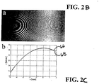
- a delay of 2.18 ps (654 ⁇ m) was introduced between the sample and the reference arms.
- the interference pattern for this setup is shown in Fig. 2B .
- FIG. 2C a measured surface profile along a horizontal line is plotted as a solid line 66 in Fig. 2C .
- FIG. 2C thus illustrates that the profile of the lens (solid line 66) measured using the described system agrees with a calculated profile (dashed line 68).
- the differences between the measured and the calculated profiles can be attributed to the loss of fringe contrast on the right side of the frame and due to low fringe density on the left side.
- the specimen surface is not optically smooth, but contains many surface irregularities.
- the interference between the sample and the reference is manifested by a granular speckle pattern.
- This pattern has a characteristic speckle size that matches the system's point-spread function.
- the coherence length is N times larger, since it is determined only by the spectral width of each spectrally encoded spot.
- the coherence length (310 ⁇ m) was smaller than the confocal parameter (2.7 mm) and therefore determined the axial resolution. The large depth of focus allowed imaging over a range equivalent to the confocal parameter by scanning only the optical path length of the reference arm.
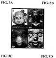
- FIG. 3A The image of the doll's face in Fig. 3A was obtained using white light illumination and a standard CCD camera. It should be noted that the scale bar in FIG. 3A represents 4 mm while the scale bars in FIGs. 3B - 3D represent 1 mm.
- FIG. 3B the standard spectrally encoded-two-dimensional image is shown.
- the surface height, measured by 3D spectrally encoded imaging, is represented as a gray scale image, where z values closer to the probe have a higher pixel intensity.
- This image is obtained by blocking a reference arm in the system of FIG. 2 .
- the light returned from the reference arm was allowed to interfere with that of the sample arm, a speckle pattern was observed in portions of the image.
- a full three-dimensional data set was acquired by capturing 45 frames as the reference arm path length was scanned in steps of 100 ⁇ m.
- FIG. 3D corresponds to a surface rendering of the dolls face using the data shown in Fig. 3C .
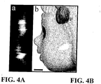
- a sagital (y-z) section was plotted ( Fig. 4A ) from the data.
- the sagital section was placed next to the actual doll's profile ( Fig. 4B ).
- the measurement revealed an axial resolution of approximately 330 ⁇ m (FWHM of the coherence envelope), which is in reasonable agreement with the predicted axial resolution of 310 ⁇ m.
- the scale bar visible in Fig. 4B ) is 1mm.
- Three dimensional (3-D) spectrally-encoded imaging can be used in many configurations to suit specific applications.
- this method is capable of measuring a surface within a volume of 50x50x30 millimeters (x, y, z respectively) with, typically, 200x200x280 resolution points (250 ⁇ m transverse spot-size and 107 ⁇ m axial resolution).
- a CCD camera 10,000 frames per second
- a rapidly scanning optical delay line in the reference arm the three-dimensional data set could be captured and displayed in real time (30 frames per second).
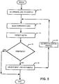
- a technique for producing a three-dimensional image begins by illuminating a line on a sample and then scanning a reference line as shown in processing blocks 70, 72.
- the depth information is determined as shown in block 74. In one embodiment, this is achieved by measuring the number of fringes within a spot on the sample (e.g. analyzing the number of fringes using a fast Fourier Transform(FFT) or other technique) and translating this information to depth information.
- FFT fast Fourier Transform
- the techniques and apparatus described above can be used to provide three-dimensional macroscopic images using a phase-sensitive spectrally encoded imaging technique.
- volume data can be acquired through a single optical fiber without any additional modifications to the spectrally-encoded imaging device.
Description
- This invention relates generally optical imaging and more particularly to a method and apparatus for performing three-dimensional surface measurements.
- As is known in the art, optical techniques for surface profilometry are commonly performed using interferometric measurements. Analyzing the interference fringe pattern formed by overlap of a reflected wave from an optically smooth surface with a reference wave, enables surface profile measurements with high accuracy. Projecting an interference fringe pattern on an object surface is effective for probing rough surfaces. High-resolution, point-by-point measurements of rough surfaces have been demonstrated using a long coherence length source with a Fizeau interferometer and with a broadband source.
- White-light interferometry is capable of simultaneously imaging large field of views by scanning only the path length of a reference arm. In this approach, light reflected from the surface interferes with a reference wave to form a speckle pattern on a camera. When the reference optical path length is scanned, each individual speckle exhibits an intensity modulation. The surface height is determined at the maximum point of the modulation envelope. White-light interferometry is an extremely robust technique, allowing for high resolution imaging in three dimensions with a large field of view.
- Depth resolved imaging with a large, three-dimensional field of view is more challenging when utilizing small diameter flexible imaging probes such as borescopes, laparoscopes, and endoscopes. Confocal imaging through a fiber-bundle using a lens with a high numerical aperture is one solution to this problem. The three-dimensional field of view for these devices, however, is limited to less than a few millimeters due to the small objective lens clear aperture and low f-number required for high-resolution optical sectioning.
- Other methods, such as stereo imaging and structured illumination have been proposed.
- These methods all require additional hardware for the probe, increasing the size, cost, and complexity of these devices.
- An example of a scanning confocal microscopy system, especially useful for endoscopy, is described in
WO99/44089 - In another example, Froehly, L. et al. "Multiplexed 3D imaging device using wavelength encoded spectral interferometry: a proof of principle", Optical Communications, vol. 222, no. 1-6, 1 July 2003, pages 127-136, there is disclosed a system for 3D imaging using spectral interferometry. The system comprises includes a fixed reference arm length l0 and provides information regarding surface irregularities at only one particular depth of the sample, for example on the surface of the relatively flat "tape on glass" sample used in the reference.
- The present invention provides a method according to
claim 1 and an apparatus according to claim 23 for obtaining three-dimensional information of a sample. - In accordance with the present invention, an imaging technique includes encoding a transverse location of an object by wavelength and encoding an axial or depth coordinate of each point on the object by phase. With this particular arrangement, a technique for generating two-dimensional images of an object as well as surface profile measurements of the object is provided. By combining the surface profile with the two dimensional image, a three-dimensional spectrally-encoded imaging technique is provided. Encoding the depth (or height) information is accomplished by changing a phase length of a reference path and detecting phase differences in signals reflected from the surface of the object each time the phase length of the reference path is changed. The phase length of the reference path establishes a coherence length (CL) at the surface being measured. Thus by changing the phase length of the reference path, a different coherent length is established. By detecting phase differences in signals reflected from the surface of the object each time the phase length of the reference path is changed, the height at different points along the surface can be detected.
- In one embodiment, a surface profile of an object is measured by utilizing the technique of the present invention in conjunction with a probe of the type described in published
PCT application number WO 02/038040 A2 WO 02/038040 A2 - Using the phase-sensitive spectrally encoded imaging techniques of the present invention, volume data can be acquired through a single optical fiber. The present invention thus makes possible three-dimensional macroscopic imaging within the confines of a miniature, flexible probe. Data measured using techniques of the present invention has clearly demonstrated the potential of this technology for probe-based imaging for industrial applications. It should be appreciated, however, that the phase-sensitive spectrally encoded imaging technique of the present invention can also be used in medical and other applications. For example, phase-sensitive spectrally encoded imaging technique of the present invention can be used to visualize multiply scattering tissues in three-dimensions for biomedical applications.
- According to the present invention, a method for measuring a surface of a specimen includes operating a beam provided as spectrally-encoded points of a spectrum, focusing the beam onto a specimen disposed in a sample arm, scanning the beam in a first direction across the specimen to create a two dimensional image, changing a path length of a reference path and generating an interference pattern with a reflection from light from the sample and reference arms. The signals from the sample and reference arms are then directed to a detection arm where they are combined. With this particular arrangement, a method for detecting a height of a surface is provided. In order to obtain a surface profile of the specimen, the propagation path length of the reference path is changed and interference patterns at each changed path length are used to provide the height information.
- In an embodiment of the present invention, a system includes a source, a splitter/combiner having a first port coupled to the source, having a second port coupled to a reference path, having a third port coupled to a sample path and having a fourth port coupled to a detection path. The sample path includes a dispersive element which provides a spectrally encoded focal plane. The reference path includes a path length change device which is adapted to change a propagation path length of light propagating in the reference path. With this particular arrangement, system for three-dimensional imaging is provided. By changing the propagation path length of the reference path, a phase-sensitive spectrally encoded imaging system is provided. The phase information contained in signals reflected form the specimen in the sample path can be used to provide depth (height) information of a surface. Thus, both transverse and depth information can be transmitted through a single-mode optical fiber, allowing such a system to be incorporated into a miniature probe.
- The foregoing features of this invention, as well as the invention itself, may be more fully understood from the following description of the drawings in which:
-
FIG. 1 is a block diagram of an apparatus for three-dimensional spectrally encoded imaging; -
FIG. 2 is a schematic diagram of an exemplary embodiment of an apparatus for three-dimensional spectrally encoded imaging; -
FIG. 2A is an enlarged view of the sample inFIG. 2 taken around lines 2A-2A inFIG. 2 ; -
FIG. 2B is a plot of an interference pattern provided from the system ofFIG. 2 ; -
FIG. 2C is a plot of a measured surface profile; -
FIG. 3A is an image of a doll's face obtained using white light illumination and a charge coupled device (CCD) camera; -
FIG. 3B is a conventional spectrally encoded-two-dimensional image of a doll's face obtained by blocking a reference arm in the system ofFIG 2 ; -
FIG. 3C is a gray scale image which shows a surface height obtained by determining the location of a maximum speckle intensity difference along an axial (z) axis; -
FIG. 3D . is a doll's face represented by surface 3-D rendering; -
FIG. 4A is plot of sagital (y-z) section from a data set; -
FIG. 4B is a plot of a doll's actual profile; and -
FIG. 5 is a flow diagram which illustrates an exemplary technique for three-dimensional spectrally encoded imaging. - Referring now to
FIG. 1 , a three-dimensional spectrally encodedimaging system 10 includes asource 12 coupled to abeam splitter 14 atfirst port 14a. It should be appreciated thatbeam splitter 14 may be implement using any techniques now known or later discovered. For example,splitter 14 may be provided as a fiber optic beam splitter, a free space splitter or a glass plate splitter. - The
system 10 includes areference path 16 coupled to asecond port 14b of thebeam splitter 14 and asample path 18 coupled to athird port 14c of thebeam splitter 14. Thereference path 16 includes a path-length change device 17. Path-length change device 17 is adapted to change a propagation path length of light propagating in thereference path 16. Thedevice 17 allows the optical path length of thereference arm 17 to be changed in a controlled and known manner. In some embodiments,device 17 may be provided such that it can introduce a change in the group delay of optical signals propagating inpath 16. Such a change in group delay may or may not be accompanied by a physical change in the optical path length of the reference arm. Changes in group delay in optical signals may be desired to reduce speckle artifacts and possibly result in increased system sensitivity. It should be appreciated that if the reference arm would not include a path-length change device 17, then the depth at only a single spot along a scan line of a sample may be computed. - The
sample path 18 has disposed therein a sample 19 (also referred to herein as a specimen 19). Thesample path 18 may optionally include one or more of adispersive elements 18a, abeam focusing device 18b and a scanning element (or more simply, a scanner) 18c as described in co-pending application no. 09/709,162. The dispersive element may be provided, for example, as a diffraction grating and in response to a signal fed thereto from the beam splitter, the dispersive element disperses the signal into a spectrum in an image plane. The dispersive element may also be provided as a dispersive prism, a fiber grating, a blazed grating, a grism, a holographic lens grating or any other element which provides angular separation of light signals propagating at different wavelengths. That is, in response to light signals incident thereon, the dispersive element directs different wavelengths in different directions or, stated differently, the dispersive element disperses the spectrum of the light signal provided thereto to provide a spectrally encoded focal plane. - The
beam focusing device 18b focuses individual spectrally-encoded points toward thesample 19 disposed in thesample path 18. The beam focusing device may be provided, for example, from an optical system such as a lens system. - The
scanning element 18c, scans the spectrally-encoded beam across thespecimen 19 to produce a two-dimensional image. It should be understood that the positions of thedispersive device 18a andbeam focusing device 18b are selected in accordance with the requirements and needs of the particular application. - It should be appreciated that in some embodiments, it may be desirable to provide the
dispersive element 18a thescanner 18c and thebeam focusing device 18b as separate elements. For example, thedispersive element 18a may be provided as a diffraction grating, thebeam focusing device 18b may be provided as a lens disposed to focus the beam on the specimen and thescanner 18c may be provided as a galvanometric scanner disposed to direct light to and from the diffraction grating. Thedispersive element 18a,scanner 18c andlens system 18b may be combined in a single housing. - In other embodiments, however, it may be desirable to provide the
dispersive element 18a, thescanner 18c and thelens system 18b as a single integrated element. Alternatively still, the functions performed by thedispersive element 18a,scanner 18c andlens system 18b may be provided from a single device. - In order to obtain a surface profile of the
specimen 19, the propagation path length of thereference path 16 is changed. In one embodiment, the path length of thereference path 16 is changed by providing thedevice 17 as a movable reflective device disposed at the end of the reference arm. Movement of the reflective device changes the path length of thereference arm 16. In one embodiment, the movable reflective device can be provided as a mirror disposed on a movable platform at the end of thereference arm 16. Movement of the platform (and thus the mirror) changes the optical path length of thereference arm 16. Other techniques for changing the path length of the reference path, may of course, also be used. - The
source 12 emits a light signal to thebeam splitter 14 which splits the light and provides a first portion of the light signal to thereference arm 16 and a second portion of the signal to thesample arm 18. The light impinges upondevice 17 andsample 19 in the reference andsample paths ports combiner 14. Ideally, the splitting ratio of the splitter/combiner 14 is selected such that an equal amount of reflected power is received at each of thesplitter ports - The reference line can also include an optical attenuator (not shown in
FIG. 1 ) having an attenuation setting selected to adjust the strength of a reference beam reflected from a reflective device to increase (and in some cases maximize) the contrast of an interference pattern generated from the reflected reference beam and the reflected beam from the sample arm. - Signals reflected from the reference and sample
arms detector arm 20 via splitter/combiner circuit 14. Thedetector arm 20 receives signals fed thereto and detects depth. As mentioned above, it is possible for detector arm 21 to analyze a pattern provided thereto without scanning the reference arm.Detector 21b can thus determine depth information at a single point in an image, along a line in an image or in an entire two-dimensional image (i.e. to provide a three-dimensional image). - In one embodiment, the detector receives time-domain measurements and provides depth information by using a Fourier transform (e.g. an FFT). In another embodiment, detector arm 21 includes a
dispersive device 21a and adetector 21b. In this case, the dispersive element disperses the wavelengths of an optical signal provided thereto and the dispersed spectrum is detected by thedetector 21b. Thedispersive device 21a may be provided from a number of devices including but not limited to a grating or a dispersive prism. Similarly, thedetector 21b may be provided from a number of devices including but not limited to a charge coupled device (CDD) camera. - Referring now to
FIG. 2 , asystem 30 for performing three-dimensional spectrally encoded imaging includes asource 32 having a relatively broad bandwidth coupled to a singlemode fiberoptic interferometer 34 at first port 34a. Areference path 36 is coupled to a second port 34b of theinterferometer 34, asample path 42 is coupled to a third port 34c of theinterferometer 34 and a detection path 52 is coupled to a fourth port 34d of theinterferometer 34. - In one embodiment, the
source 32 is provided as a broad-bandwidth titanium-sapphire source having a center wavelength of 860 nanometers (nm) and an FWHM bandwidth of 200 nm while theinterferometer 34 is provided as a 50/50 Michelson interferometer and thesample arm 42 includes a diffraction grating (600 lines/mm) to disperse the spectrum in the horizontal image plane (x-axis). A lens 48 (f = 75 mm, beam diameter = 1 mm) focuses the individual spectrally-encoded points onto aspecimen 50. - The beam was scanned in the vertical dimension (y-axis) by a galvanometric scanner (60 Hz) 44 to create a two-dimensional image. These parameters resulted in a spatial transverse resolution of approximately 40 µm. The image was comprised of approximately 585 x 585 resolvable points; each transverse spot contained a bandwidth of 0.34 nm. The overall power on the sample was 10 mW.
- In order to obtain surface profiles, the path length of the
reference arm 36 was controlled by moving amirror 40 mounted on a translation stage. The power of the reference beam was attenuated using a neutral density (ND) filter 308 to maximize the contrast of the interference pattern. - Referring now to
FIGs. 2 and 2A , by placing the mirror in afirst location 41a, the reference arm is provided having a first path length. This path length results in a first coherence length (CL) 41a. Reflections from the surface of thesample 50 at this coherence length represent a first depth. When the mirror is moved to a second location 41b, the reference arm is provided having a second path length in this example, the second reference arm path length is longer than the first reference arm path length. This path length results in a second coherence length (CL) 41b. Reflections from the surface of thesample 50 at this second coherence length represent a second depth. Similarly, when the mirror is moved to athird location 41c, the reference arm is provided having a third path length in this example, the third reference arm path length is longer than the first and second reference arm path lengths. The third path length results in a third coherence length (CL) 41c. Reflections from the surface of thesample 50 at this second coherence length represent a third depth. In this manner, the depth information of the surface sample is provided. - Although this example utilizes only three coherence lengths, it should be appreciated that the any desired number of coherence lengths can be used. The particular number of coherence lengths to use will depend upon the particular application. Its should also be appreciated that while the coherence lengths are changed by moving a mirror to adjust a phase length of the reference path, any technique which effectively changes the coherence length such that phase can be used to determine surface depth of a sample can also be used.
- Referring again to
FIG. 2 , at the detection path 52, the signals from the sample and reference arms are combined and detection is performed. In one embodiment, the fields from the sample andreference arms array 60. It should be appreciated that the focusing function provided bylens 58 could also be provided at the output of the combiner (i.e. output 34d) or at the input to the detector arm. For example, if a fiber optic cable were used to coupleinterferometer 34 to detector 52, then the focusing function could be accomplished at the detector end the of fiber optic cable. Vertical scanning was performed by anothergalvanometric scanner 54 which was synchronized with the sample arm y-axis scanner. The resulting interference pattern was viewed on a display 62 (e.g. a monitor) in real time, digitized, and stored. - At each horizontal line on the CCD, the intensity is given by:

- To demonstrate the ability of this scheme to probe optically smooth surfaces, a plano-convex lens (Melles-Griot, f = 1 m, BK7 glass) was placed in the sample arm (
e.g. lens 48 was provided as a plano-convex lens), with its convex surface facing toward the grating. In order to match the optical path length over the entire field of view, an additional two lenses, in a confocal configuration, were placed at the sample arm between the scanner and the diffraction grating. A delay of 2.18 ps (654 µm) was introduced between the sample and the reference arms. The interference pattern for this setup is shown inFig. 2B . The surface profile was obtained using the algorithm described in "Linear techniques of phase measurement by femtosecond spectral interferometry for applications in spectroscopy," J. Opt. Soc. .FIG. 2A is a two-dimensional spectrally-encoded interferogram provided from the curved surface of a lens (f= 1 m). - Referring Now to
Fig. 2C , a measured surface profile along a horizontal line is plotted as asolid line 66 inFig. 2C . For comparison, the spherical curve of the lens's radius, calculated according to R = f·(n-1), (n = 1.5187), is plotted as a dashed line 68 (Fig. 2C). FIG. 2C thus illustrates that the profile of the lens (solid line 66) measured using the described system agrees with a calculated profile (dashed line 68). The differences between the measured and the calculated profiles can be attributed to the loss of fringe contrast on the right side of the frame and due to low fringe density on the left side. When the sample contains steep local slopes, the fringe pattern became too dense to be resolved by the imaging system. This limitation prevented the system from measuring optically smooth surfaces with slopes greater than
- In most industrial and medical applications, the specimen surface is not optically smooth, but contains many surface irregularities. When the surface is rough and the diffraction-limited point-spread function of the imaging system is broad in comparison to the microscopic surface variations, the interference between the sample and the reference is manifested by a granular speckle pattern. This pattern has a characteristic speckle size that matches the system's point-spread function. The depth of the speckle pattern along the z axis is defined by the coherence length,

- To demonstrate the ability of a 3-D spectrally-encoded imaging apparatus to measure the profile of rough surfaces, the face of a small plastic doll was imaged. The doll's face is shown in
Fig. 3A . The image of the doll's face inFig. 3A was obtained using white light illumination and a standard CCD camera. It should be noted that the scale bar inFIG. 3A represents 4 mm while the scale bars inFIGs. 3B - 3D represent 1 mm. - In
FIG. 3B , the standard spectrally encoded-two-dimensional image is shown. The surface height, measured by 3D spectrally encoded imaging, is represented as a gray scale image, where z values closer to the probe have a higher pixel intensity. This image is obtained by blocking a reference arm in the system ofFIG. 2 . When the light returned from the reference arm was allowed to interfere with that of the sample arm, a speckle pattern was observed in portions of the image. A full three-dimensional data set was acquired by capturing 45 frames as the reference arm path length was scanned in steps of 100 µm. The natural logarithm of the absolute value of the difference between consecutive frames was calculated, followed by moderate volumetric smoothing (kernel = 3x3x3 pixels). The surface height was obtained by determining the location of the maximum speckle intensity difference along the axial (z) axis (displayed as a gray scale image inFigure 3C). FIG. 3D corresponds to a surface rendering of the dolls face using the data shown inFig. 3C . - Referring now to
FIGs. 4A and 4B , for estimating the experimental depth resolution a sagital (y-z) section was plotted (Fig. 4A ) from the data. The sagital section was placed next to the actual doll's profile (Fig. 4B ). The measurement revealed an axial resolution of approximately 330 µm (FWHM of the coherence envelope), which is in reasonable agreement with the predicted axial resolution of 310 µm. The scale bar (visible inFig. 4B ) is 1mm. - Three dimensional (3-D) spectrally-encoded imaging can be used in many configurations to suit specific applications. For example, this method is capable of measuring a surface within a volume of 50x50x30 millimeters (x, y, z respectively) with, typically, 200x200x280 resolution points (250 µm transverse spot-size and 107 µm axial resolution). Using a CCD camera (10,000 frames per second) and a rapidly scanning optical delay line in the reference arm the three-dimensional data set could be captured and displayed in real time (30 frames per second).
- Referring now to
Fig. 5 , a technique for producing a three-dimensional image begins by illuminating a line on a sample and then scanning a reference line as shown in processing blocks 70, 72. Next, the depth information is determined as shown inblock 74. In one embodiment, this is achieved by measuring the number of fringes within a spot on the sample (e.g. analyzing the number of fringes using a fast Fourier Transform(FFT) or other technique) and translating this information to depth information. As shown indecision block 76, if there are no more lines on the sample to detect, then processing ends. Otherwise a next line on the sample is selected and illuminated as shown inblocks - In summary the techniques and apparatus described above can be used to provide three-dimensional macroscopic images using a phase-sensitive spectrally encoded imaging technique. Using the techniques of the present invention, volume data can be acquired through a single optical fiber without any additional modifications to the spectrally-encoded imaging device. These features make three-dimensional imaging within the confines of a miniature, flexible probe possible.
- Although only a few exemplary embodiments of this invention have been described in detail above, those skilled in the art will readily appreciate that many modifications are possible in the exemplary embodiments without materially departing from the novel teachings and advantages of this invention. Accordingly, all such modifications are intended to be included within the scope of this invention as defined in the following claims.
Claims (36)
- A method for obtaining three-dimensional information associated with at least one sample (19, 50), the method comprising:receiving at least one first electro-magnetic radiation (14c) from a sample arm (18, 42) based on a transversely spectrally dispersed electro-magnetic radiation provided to the at least one sample (19, 50);the first electro-magnetic radiation (14c) including information identifying at least one portion of the at least one sample (19, 50);receiving at least one second electro-magnetic radiation (14b) from a reference arm (16, 36);generating first interference information based on the first and second electro-magnetic radiations (14c, 14b), the first interference information being from a first depth (41a') within the at least one sample (19, 50) corresponding to a first path length of the reference arm (16, 36);obtaining at least one relative phase between the at least one first electro-magnetic radiation (14c) being returned from the at least one sample (19, 50) and the at least one second electro-magnetic radiation (14b) returned from the reference arm (16, 36) to determine at least one relative depth location of the at least one portion,changing the reference arm (16, 36) from the first path length to a second path length different from the first path length;generating second interference information based on changing the reference arm (16, 36) from the first path length to the second path length,
the second interference information being from a second depth (41b') or a third depth (41c') within the at least one sample (19, 50);determining a surface profile of the at least one sample (19, 50) based on a location of a maximum speckle intensity difference between consecutive frames in an axial direction; andproviding the three-dimensional information associated with the at least one sample (19, 50) as a function of the first interference information, the second interference information, and the surface profile. - The method according to claim 1, wherein the reference arm (16, 36) is changed from the first path length to the second path length by moving a reflective surface (40) in the reference arm (16, 36) from a first position (41a) to either a second position (41b) or to a third position (41c).
- The method according to claim 1, wherein at least one of the first interference information or the second interference information is generated by combining and transversely spatially dispersing the first and second electro-magnetic radiations (14c, 14b) using a dispersive arrangement (56).
- The method according to claim 3, further comprising providing the dispersed electro-magnetic radiation to an imaging system (60) so as to generate the three-dimensional information.
- The method according to claim 4, wherein the dispersed electro-magnetic radiation is provided onto a charge-coupled device (60).
- The method according to claim 1, further comprising:spectrally dispersing at least two wavelengths of at least one particular electro-magnetic radiation provided on the at least one portion of the at least one sample (19, 50), each of the at least two wavelengths being utilized to determine at least one respective transverse location of a plurality of transverse locations of the at least one portion;andproviding the three-dimensional information based on each of the plurality of transverse locations and the at least one relative depth location.
- The method according to claim 6, further comprising:
transversely scanning the at least one first electro-magnetic radiation (14c) across the at least one portion of the sample (19, 50) in one dimension to obtain three-dimensional data based on the plurality of transverse locations. - The method according to claim 6, wherein the information is provided as a function of the two-dimensional data.
- The method according to claim 8, wherein the information is a three-dimensional information for the at least one portion which is obtained based on the two-dimensional data.
- The method according to claim 6, wherein the information is a three-dimensional information for the at least one portion.
- The method according to claim 6, wherein the at least one first electro-magnetic radiation (14c) and the at least one second electro-magnetic radiation (14b) have a first phase relationship, and wherein the at least one relative phase is determined by:detecting a first interference signal produced by an interference between a phase of the first and second electro-magnetic radiations (14c, 14b) having the first phase relationship;modifying a phase length of the reference (40) to a second phase relationship, and receiving at least one third electro-magnetic radiation from the sample (19, 50) and at least one fourth electro-magnetic radiation;detecting a second interference signal produced by an interference between a phase of the third and fourth electro-magnetic radiations having the second phase relationship; andprocessing the first and second interference signals to provide interference data.
- The method according to claim 11, wherein the information is provided based on the interference information.
- The method according to claim 12, wherein the information includes depth information of the at least one portion.
- The method according to claim 13, wherein the depth information is determined by measuring the first interference signal.
- The method according to claim 14, wherein the depth information is further determined by measuring the second interference signal.
- The method according to claim 13, wherein the second and fourth electro-magnetic radiations have different phases.
- The method according to claim 12, wherein the information includes height information of the at least one portion at a plurality of transverse locations on the at least one portion.
- The method according to claim 6, further comprising:
effectuating discrete changes in a length of a path (36) of the reference (40) to generate the at least one relative phase. - The method according to claim 6, wherein the at least one transverse location is a plurality of transverse locations.
- The method according to claim 6, wherein the at least one location includes a plurality of locations.
- The method according to claim 20, wherein each of the wavelengths is associated with a respective one of the locations.
- The method according to claim 6, wherein the at least one particular electro-magnetic radiation is provided on at least two separate respective locations on the sample (19, 50).
- An apparatus (10, 30) for obtaining three-dimensional information associated with at least one sample (19, 50), comprising:at least one first arrangement (14, 34) configured to receive:at least one first electro-magnetic radiation (14c) from a sample arm (18, 42) based on a transversely spectrally dispersed electro-magnetic radiation provided to the at least one sample (19, 50),
the first electro-magnetic radiation (14c) including information identifying at least one portion of the at least one sample (19, 50), andat least one second electro-magnetic radiation (14b) from a reference arm (16, 36);at least one second arrangement (56) configured to:generate first interference information based on the first and second electro-magnetic radiations (14c, 14b),
the first interference information being from a first depth (41a') within the at least one sample (19, 50) corresponding to a first path length of the reference arm (16, 36),obtain at least one relative phase between the at least one first electro-magnetic radiation (14c) being returned from the at least one sample (19, 50) and the at least one second electro-magnetic radiation (14b) returned from the reference arm (16, 36) to determine at least one relative depth location of the at least one portion; andgenerate second interference information based on the reference arm (16, 36) being changed from the first path length to a second path length different from the first path length,
the second interference information being from a second depth (41b') or a third depth (41c') within the at least one sample (19, 50); andat least one third arrangement (20, 60) configured to:determine a surface profile of the at least one sample (19, 50) based on a location of a maximum speckle intensity difference between consecutive frames in an axial direction; andprovide the three-dimensional information associated with the at least one sample (19, 50) specimen as a function of the first interference information, the second interference information, and the surface profile. - The apparatus according to claim 23, further comprising a dispersive arrangement (56) configured to combine and transversely spatially disperse the first and second electro-magnetic radiations (14c, 14b) to generate the three-dimensional information.
- The apparatus according to claim 24, further comprising a charge-coupled device (60) configured to receive the dispersed electro-magnetic radiation.
- The apparatus according to claim 23, further comprising:
at least one further arrangement configured to:provide at least two wavelengths of at least one particular electro-magnetic radiation provided on the at least one portion of the at least one sample (19, 50), anddetermine, using each of the at least two wavelengths, at least one respective transverse location of a plurality of transverse location of the at least one portion,wherein the at least one second arrangement is configured to provide the information of the portion based on the transverse location and the relative depth location. - The apparatus according to claim 26, further comprising:
at least one fourth arrangement configured to transversely scan the at least one first electro-magnetic radiation (14c) across the at least one portion of the sample (19, 50) in one dimension to obtain three-dimensional data based on the transverse locations. - The apparatus according to claim 27, wherein the information is provided as a function of the two-dimensional data.
- The apparatus according to claim 28, wherein the information is a three-dimensional information for the at least one portion which is obtained based on the two-dimensional data.
- The apparatus according to claim 26, wherein the information is a three-dimensional information for the at least one portion.
- The apparatus according to claim 26, further comprising a dispersive arrangement (56) configured to combine and transversely spatially disperse the first and second electro-magnetic radiations (14c, 14b) to generate the information.
- The apparatus according to claim 26, further comprising:
at least one fifth arrangement configured to effectuate discrete changes in a length of a path (36) of the reference (40) to generate the at least one relative phase. - The apparatus according to claim 26, wherein the at least one transverse location is a plurality of transverse locations.
- The apparatus according to claim 26, wherein the at least one location includes a plurality of locations.
- The apparatus according to claim 34, wherein each of the wavelengths is associated with a respective one of the plurality of locations.
- The apparatus according to claim 26, wherein the at least one particular electro-magnetic radiation is provided on at least two separate respective locations on the at least one sample (19, 50).
Applications Claiming Priority (2)
| Application Number | Priority Date | Filing Date | Title |
|---|---|---|---|
| US52568403P | 2003-11-28 | 2003-11-28 | |
| PCT/US2004/039454 WO2005054780A1 (en) | 2003-11-28 | 2004-11-24 | Method and apparatus for three-dimensional spectrally encoded imaging |
Publications (2)
| Publication Number | Publication Date |
|---|---|
| EP1687587A1 EP1687587A1 (en) | 2006-08-09 |
| EP1687587B1 true EP1687587B1 (en) | 2020-01-08 |
Family
ID=34652372
Family Applications (1)
| Application Number | Title | Priority Date | Filing Date |
|---|---|---|---|
| EP04817883.4A Active EP1687587B1 (en) | 2003-11-28 | 2004-11-24 | Method and apparatus for three-dimensional spectrally encoded imaging |
Country Status (4)
| Country | Link |
|---|---|
| US (1) | US7551293B2 (en) |
| EP (1) | EP1687587B1 (en) |
| JP (2) | JP5214883B2 (en) |
| WO (1) | WO2005054780A1 (en) |
Families Citing this family (185)
| Publication number | Priority date | Publication date | Assignee | Title |
|---|---|---|---|---|
| EP1434522B1 (en) | 2000-10-30 | 2010-01-13 | The General Hospital Corporation | Optical systems for tissue analysis |
| US9295391B1 (en) | 2000-11-10 | 2016-03-29 | The General Hospital Corporation | Spectrally encoded miniature endoscopic imaging probe |
| EP2333523B1 (en) * | 2001-04-30 | 2020-04-08 | The General Hospital Corporation | Method and apparatus for improving image clarity and sensitivity in optical coherence tomography using dynamic feedback to control focal properties and coherence gating |
| AT503309B1 (en) | 2001-05-01 | 2011-08-15 | Gen Hospital Corp | DEVICE FOR DETERMINING ATHEROSCLEROTIC BEARING BY MEASURING OPTICAL TISSUE PROPERTIES |
| US7355716B2 (en) | 2002-01-24 | 2008-04-08 | The General Hospital Corporation | Apparatus and method for ranging and noise reduction of low coherence interferometry LCI and optical coherence tomography OCT signals by parallel detection of spectral bands |
| EP1426411A1 (en) * | 2002-12-06 | 2004-06-09 | KRATON Polymers Research B.V. | Styrenic block copolymer compositions to be used for the manufacture of transparent, gel free films |
| AU2004206998B2 (en) | 2003-01-24 | 2009-12-17 | The General Hospital Corporation | System and method for identifying tissue using low-coherence interferometry |
| US7643153B2 (en) | 2003-01-24 | 2010-01-05 | The General Hospital Corporation | Apparatus and method for ranging and noise reduction of low coherence interferometry LCI and optical coherence tomography OCT signals by parallel detection of spectral bands |
| AU2004225188B2 (en) | 2003-03-31 | 2010-04-15 | The General Hospital Corporation | Speckle reduction in optical coherence tomography by path length encoded angular compounding |
| EP2030563A3 (en) | 2003-06-06 | 2009-03-25 | The General Hospital Corporation | Process and apparatus for a wavelength tuning source |
| EP2293031B8 (en) | 2003-10-27 | 2024-03-20 | The General Hospital Corporation | Method and apparatus for performing optical imaging using frequency-domain interferometry |
| JP4750786B2 (en) * | 2004-05-29 | 2011-08-17 | ザ ジェネラル ホスピタル コーポレイション | Chromatic dispersion compensation process, system and software configuration using refractive layer in optical coherence tomography (OCT) imaging |
| JP4995720B2 (en) | 2004-07-02 | 2012-08-08 | ザ ジェネラル ホスピタル コーポレイション | Endoscopic imaging probe with double clad fiber |
| EP1782020B1 (en) | 2004-08-06 | 2012-10-03 | The General Hospital Corporation | Process, system and software arrangement for determining at least one location in a sample using an optical coherence tomography |
| WO2006024014A2 (en) | 2004-08-24 | 2006-03-02 | The General Hospital Corporation | Process, system and software arrangement for measuring a mechanical strain and elastic properties of a sample |
| US8208995B2 (en) | 2004-08-24 | 2012-06-26 | The General Hospital Corporation | Method and apparatus for imaging of vessel segments |
| EP2302364A3 (en) | 2004-09-10 | 2011-04-06 | The General Hospital Corporation | System and method for optical coherence imaging |
| JP4997112B2 (en) | 2004-09-29 | 2012-08-08 | ザ ジェネラル ホスピタル コーポレイション | Apparatus for transmitting at least one electromagnetic radiation and method of manufacturing the same |
| US7995210B2 (en) | 2004-11-24 | 2011-08-09 | The General Hospital Corporation | Devices and arrangements for performing coherence range imaging using a common path interferometer |
| JP2008521516A (en) | 2004-11-29 | 2008-06-26 | ザ ジェネラル ホスピタル コーポレイション | Configuration, apparatus, endoscope, catheter, and method for performing optical image generation by simultaneously illuminating and detecting multiple points on a sample |
| EP2085929A1 (en) | 2005-04-28 | 2009-08-05 | The General Hospital Corporation | Evaluating optical coherence tomography information for an anatomical structure |
| WO2007084175A1 (en) * | 2005-05-04 | 2007-07-26 | University Of Rochester | Interferometric apparatus and method for sizing nanoparticles |
| EP1887926B1 (en) * | 2005-05-31 | 2014-07-30 | The General Hospital Corporation | System and method which use spectral encoding heterodyne interferometry techniques for imaging |
| EP1889037A2 (en) | 2005-06-01 | 2008-02-20 | The General Hospital Corporation | Apparatus, method and system for performing phase-resolved optical frequency domain imaging |
| KR101387454B1 (en) | 2005-08-09 | 2014-04-22 | 더 제너럴 하스피탈 코포레이션 | Apparatus, methods and storage medium for performing polarization-based quadrature demodulation in optical coherence tomography |
| US8784336B2 (en) | 2005-08-24 | 2014-07-22 | C. R. Bard, Inc. | Stylet apparatuses and methods of manufacture |
| EP2275026A1 (en) | 2005-09-29 | 2011-01-19 | The General Hospital Corporation | Arrangements and methods for providing multimodality microscopic imaging of one or more biological structures |
| US8205019B2 (en) | 2005-09-30 | 2012-06-19 | Intel Corporation | DMA transfers of sets of data and an exclusive or (XOR) of the sets of data |
| US7889348B2 (en) | 2005-10-14 | 2011-02-15 | The General Hospital Corporation | Arrangements and methods for facilitating photoluminescence imaging |
| EP1971848B1 (en) * | 2006-01-10 | 2019-12-04 | The General Hospital Corporation | Systems and methods for generating data based on one or more spectrally-encoded endoscopy techniques |
| WO2007084903A2 (en) | 2006-01-19 | 2007-07-26 | The General Hospital Corporation | Apparatus for obtaining information for a structure using spectrally-encoded endoscopy techniques and method for producing one or more optical arrangements |
| US9087368B2 (en) | 2006-01-19 | 2015-07-21 | The General Hospital Corporation | Methods and systems for optical imaging or epithelial luminal organs by beam scanning thereof |
| US7538859B2 (en) | 2006-02-01 | 2009-05-26 | The General Hospital Corporation | Methods and systems for monitoring and obtaining information of at least one portion of a sample using conformal laser therapy procedures, and providing electromagnetic radiation thereto |
| EP1983921B1 (en) | 2006-02-01 | 2016-05-25 | The General Hospital Corporation | Systems for providing electromagnetic radiation to at least one portion of a sample using conformal laser therapy procedures |
| WO2007092911A2 (en) | 2006-02-08 | 2007-08-16 | The General Hospital Corporation | Methods, arrangements and systems for obtaining information associated with an anatomical sample using optical microscopy |
| WO2007101026A2 (en) | 2006-02-24 | 2007-09-07 | The General Hospital Corporation | Methods and systems for performing angle-resolved fourier-domain optical coherence tomography |
| US20090323061A1 (en) * | 2006-02-28 | 2009-12-31 | Lukas Novotny | Multi-color hetereodyne interferometric apparatus and method for sizing nanoparticles |
| US7742173B2 (en) | 2006-04-05 | 2010-06-22 | The General Hospital Corporation | Methods, arrangements and systems for polarization-sensitive optical frequency domain imaging of a sample |
| WO2007133961A2 (en) | 2006-05-10 | 2007-11-22 | The General Hospital Corporation | Processes, arrangements and systems for providing frequency domain imaging of a sample |
| US7652772B2 (en) * | 2006-05-12 | 2010-01-26 | Northwestern University | Systems, methods, and apparatuses of low-coherence enhanced backscattering spectroscopy |
| WO2007133964A2 (en) | 2006-05-12 | 2007-11-22 | The General Hospital Corporation | Processes, arrangements and systems for providing a fiber layer thickness map based on optical coherence tomography images |
| JP2009541770A (en) * | 2006-06-23 | 2009-11-26 | オプトポール テクノロジー スポルカ アクシジナ | Optical frequency domain tomography apparatus with adjustment system, optical frequency domain tomography apparatus adjustment system, method for adjusting optical frequency domain tomography apparatus, and object imaging method |
| WO2008024948A2 (en) | 2006-08-25 | 2008-02-28 | The General Hospital Corporation | Apparatus and methods for enhancing optical coherence tomography imaging using volumetric filtering techniques |
| US8838213B2 (en) | 2006-10-19 | 2014-09-16 | The General Hospital Corporation | Apparatus and method for obtaining and providing imaging information associated with at least one portion of a sample, and effecting such portion(s) |
| US7794407B2 (en) | 2006-10-23 | 2010-09-14 | Bard Access Systems, Inc. | Method of locating the tip of a central venous catheter |
| US8388546B2 (en) | 2006-10-23 | 2013-03-05 | Bard Access Systems, Inc. | Method of locating the tip of a central venous catheter |
| EP2662673A3 (en) | 2007-01-19 | 2014-06-18 | The General Hospital Corporation | Rotating disk reflection for fast wavelength scanning of dispersed broadband light |
| US20080234586A1 (en) * | 2007-03-19 | 2008-09-25 | The General Hospital Corporation | System and method for providing noninvasive diagnosis of compartment syndrome using exemplary laser speckle imaging procedure |
| WO2008118781A2 (en) | 2007-03-23 | 2008-10-02 | The General Hospital Corporation | Methods, arrangements and apparatus for utilizing a wavelength-swept laser using angular scanning and dispersion procedures |
| US10534129B2 (en) | 2007-03-30 | 2020-01-14 | The General Hospital Corporation | System and method providing intracoronary laser speckle imaging for the detection of vulnerable plaque |
| US8045177B2 (en) | 2007-04-17 | 2011-10-25 | The General Hospital Corporation | Apparatus and methods for measuring vibrations using spectrally-encoded endoscopy |
| US8115919B2 (en) | 2007-05-04 | 2012-02-14 | The General Hospital Corporation | Methods, arrangements and systems for obtaining information associated with a sample using optical microscopy |
| WO2009018456A2 (en) | 2007-07-31 | 2009-02-05 | The General Hospital Corporation | Systems and methods for providing beam scan patterns for high speed doppler optical frequency domain imaging |
| US20090062662A1 (en) | 2007-08-27 | 2009-03-05 | Remicalm, Llc | Optical spectroscopic device for the identification of cervical cancer |
| JP5536650B2 (en) | 2007-08-31 | 2014-07-02 | ザ ジェネラル ホスピタル コーポレイション | System and method for self-interfering fluorescence microscopy and associated computer-accessible media |
| JP2011500173A (en) * | 2007-10-12 | 2011-01-06 | ザ ジェネラル ホスピタル コーポレイション | System and process for optical imaging of luminal anatomical structures |
| US20090099460A1 (en) | 2007-10-16 | 2009-04-16 | Remicalm Llc | Method and device for the optical spectroscopic identification of cervical cancer |
| US7933021B2 (en) | 2007-10-30 | 2011-04-26 | The General Hospital Corporation | System and method for cladding mode detection |
| US10524691B2 (en) | 2007-11-26 | 2020-01-07 | C. R. Bard, Inc. | Needle assembly including an aligned magnetic element |
| US8781555B2 (en) | 2007-11-26 | 2014-07-15 | C. R. Bard, Inc. | System for placement of a catheter including a signal-generating stylet |
| US9521961B2 (en) | 2007-11-26 | 2016-12-20 | C. R. Bard, Inc. | Systems and methods for guiding a medical instrument |
| US9649048B2 (en) | 2007-11-26 | 2017-05-16 | C. R. Bard, Inc. | Systems and methods for breaching a sterile field for intravascular placement of a catheter |
| US10449330B2 (en) | 2007-11-26 | 2019-10-22 | C. R. Bard, Inc. | Magnetic element-equipped needle assemblies |
| JP5452500B2 (en) | 2007-11-26 | 2014-03-26 | シー・アール・バード・インコーポレーテッド | Integrated system for intravascular placement of catheters |
| US8849382B2 (en) | 2007-11-26 | 2014-09-30 | C. R. Bard, Inc. | Apparatus and display methods relating to intravascular placement of a catheter |
| US10751509B2 (en) | 2007-11-26 | 2020-08-25 | C. R. Bard, Inc. | Iconic representations for guidance of an indwelling medical device |
| US8218152B1 (en) * | 2007-12-04 | 2012-07-10 | The Board Of Trustees Of The University Of Illinois | Group refractive index reconstruction with broadband interferometric confocal microscopy |
| US11123047B2 (en) | 2008-01-28 | 2021-09-21 | The General Hospital Corporation | Hybrid systems and methods for multi-modal acquisition of intravascular imaging data and counteracting the effects of signal absorption in blood |
| US9332942B2 (en) | 2008-01-28 | 2016-05-10 | The General Hospital Corporation | Systems, processes and computer-accessible medium for providing hybrid flourescence and optical coherence tomography imaging |
| US8478382B2 (en) | 2008-02-11 | 2013-07-02 | C. R. Bard, Inc. | Systems and methods for positioning a catheter |
| US8422030B2 (en) * | 2008-03-05 | 2013-04-16 | General Electric Company | Fringe projection system with intensity modulating by columns of a plurality of grating elements |
| WO2011160068A1 (en) * | 2010-06-17 | 2011-12-22 | Purdue Research Foundation | Digital holographic method of measuring cellular activity and measuring apparatus with improved stability |
| US10426348B2 (en) | 2008-03-05 | 2019-10-01 | Purdue Research Foundation | Using differential time-frequency tissue-response spectroscopy to evaluate living body response to a drug |
| US7812968B2 (en) * | 2008-03-05 | 2010-10-12 | Ge Inspection Technologies, Lp | Fringe projection system and method for a probe using a coherent fiber bundle |
| CN101878434B (en) | 2008-04-10 | 2014-05-07 | 普拉德研究及开发股份有限公司 | Method for characterizing a geological formation traversed by a borehole |
| US8725477B2 (en) | 2008-04-10 | 2014-05-13 | Schlumberger Technology Corporation | Method to generate numerical pseudocores using borehole images, digital rock samples, and multi-point statistics |
| US7898656B2 (en) | 2008-04-30 | 2011-03-01 | The General Hospital Corporation | Apparatus and method for cross axis parallel spectroscopy |
| WO2009137701A2 (en) | 2008-05-07 | 2009-11-12 | The General Hospital Corporation | System, method and computer-accessible medium for tracking vessel motion during three-dimensional coronary artery microscopy |
| US8861910B2 (en) | 2008-06-20 | 2014-10-14 | The General Hospital Corporation | Fused fiber optic coupler arrangement and method for use thereof |
| WO2010009136A2 (en) | 2008-07-14 | 2010-01-21 | The General Hospital Corporation | Apparatus and methods for color endoscopy |
| CN102239494B (en) * | 2008-07-24 | 2014-07-23 | 加利福尼亚大学董事会 | Apparatus and method for dispersive fourier-transform imaging |
| EP2313143B1 (en) | 2008-08-22 | 2014-09-24 | C.R. Bard, Inc. | Catheter assembly including ecg sensor and magnetic assemblies |
| US8437833B2 (en) | 2008-10-07 | 2013-05-07 | Bard Access Systems, Inc. | Percutaneous magnetic gastrostomy |
| JP5731394B2 (en) | 2008-12-10 | 2015-06-10 | ザ ジェネラル ホスピタル コーポレイション | System, apparatus and method for extending imaging depth range of optical coherence tomography through optical subsampling |
| US9615748B2 (en) | 2009-01-20 | 2017-04-11 | The General Hospital Corporation | Endoscopic biopsy apparatus, system and method |
| JP2012515930A (en) | 2009-01-26 | 2012-07-12 | ザ ジェネラル ホスピタル コーポレーション | System, method and computer-accessible medium for providing a wide-field super-resolution microscope |
| CN104134928A (en) | 2009-02-04 | 2014-11-05 | 通用医疗公司 | Apparatus and method for utilization of a high-speed optical wavelength tuning source |
| US9351642B2 (en) | 2009-03-12 | 2016-05-31 | The General Hospital Corporation | Non-contact optical system, computer-accessible medium and method for measurement at least one mechanical property of tissue using coherent speckle technique(s) |
| US8311788B2 (en) | 2009-07-01 | 2012-11-13 | Schlumberger Technology Corporation | Method to quantify discrete pore shapes, volumes, and surface areas using confocal profilometry |
| EP3542713A1 (en) | 2009-06-12 | 2019-09-25 | Bard Access Systems, Inc. | Adapter for a catheter tip positioning device |
| US9445734B2 (en) | 2009-06-12 | 2016-09-20 | Bard Access Systems, Inc. | Devices and methods for endovascular electrography |
| US9532724B2 (en) | 2009-06-12 | 2017-01-03 | Bard Access Systems, Inc. | Apparatus and method for catheter navigation using endovascular energy mapping |
| BR112012001042A2 (en) | 2009-07-14 | 2016-11-22 | Gen Hospital Corp | fluid flow measurement equipment and method within anatomical structure. |
| CN102665541B (en) | 2009-09-29 | 2016-01-13 | C·R·巴德股份有限公司 | The probe used together with the equipment that the Ink vessel transfusing for conduit is placed |
| US11103213B2 (en) | 2009-10-08 | 2021-08-31 | C. R. Bard, Inc. | Spacers for use with an ultrasound probe |
| US11754488B2 (en) | 2009-12-11 | 2023-09-12 | Washington University | Opto-mechanical system and method having chaos induced stochastic resonance and opto-mechanically mediated chaos transfer |
| US20150285728A1 (en) | 2009-12-11 | 2015-10-08 | Washington University | Detection of nano-scale particles with a self-referenced and self-heterodyned raman micro-laser |
| US8704155B2 (en) * | 2009-12-11 | 2014-04-22 | Washington University | Nanoscale object detection using a whispering gallery mode resonator |
| US9012830B2 (en) * | 2009-12-11 | 2015-04-21 | Washington University | Systems and methods for particle detection |
| WO2011091012A2 (en) * | 2010-01-19 | 2011-07-28 | Si-Ware Systems | Interferometer with variable optical path length reference mirror and applications thereof |
| BR112012019354B1 (en) | 2010-02-02 | 2021-09-08 | C.R.Bard, Inc | METHOD FOR LOCATION OF AN IMPLANTABLE MEDICAL DEVICE |
| DK2542154T3 (en) | 2010-03-05 | 2020-11-23 | Massachusetts Gen Hospital | APPARATUS FOR PROVIDING ELECTROMAGNETIC RADIATION TO A SAMPLE |
| CN101799280B (en) * | 2010-03-24 | 2012-05-09 | 上海应用技术学院 | Hybrid-frequency moire image generation method based on optical-fiber two-dimensional combined coding structure |
| US9069130B2 (en) | 2010-05-03 | 2015-06-30 | The General Hospital Corporation | Apparatus, method and system for generating optical radiation from biological gain media |
| EP2575597B1 (en) | 2010-05-25 | 2022-05-04 | The General Hospital Corporation | Apparatus for providing optical imaging of structures and compositions |
| WO2011150069A2 (en) * | 2010-05-25 | 2011-12-01 | The General Hospital Corporation | Apparatus, systems, methods and computer-accessible medium for spectral analysis of optical coherence tomography images |
| JP5868961B2 (en) | 2010-05-28 | 2016-02-24 | シー・アール・バード・インコーポレーテッドC R Bard Incorporated | Device for use with a needle insertion guidance system |
| EP2575611B1 (en) | 2010-05-28 | 2021-03-03 | C. R. Bard, Inc. | Apparatus for use with needle insertion guidance system |
| US10285568B2 (en) | 2010-06-03 | 2019-05-14 | The General Hospital Corporation | Apparatus and method for devices for imaging structures in or at one or more luminal organs |
| US10401793B2 (en) | 2010-06-17 | 2019-09-03 | Purdue Research Foundation | Digital holographic method of measuring cellular activity and measuring apparatus with improved stability |
| AU2011289513B2 (en) | 2010-08-09 | 2014-05-29 | C.R. Bard, Inc. | Support and cover structures for an ultrasound probe head |
| US20120046562A1 (en) | 2010-08-20 | 2012-02-23 | C. R. Bard, Inc. | Reconfirmation of ecg-assisted catheter tip placement |
| JP5883018B2 (en) | 2010-10-27 | 2016-03-09 | ザ ジェネラル ホスピタル コーポレイション | Apparatus, system, and method for measuring blood pressure within at least one blood vessel |
| EP2632360A4 (en) | 2010-10-29 | 2014-05-21 | Bard Inc C R | Bioimpedance-assisted placement of a medical device |
| US8982355B2 (en) * | 2010-12-09 | 2015-03-17 | The United States Of America As Represented By The Administrator Of The National Aeronautics And Space Administration | Smart optical material characterization system and method |
| WO2012112977A1 (en) * | 2011-02-18 | 2012-08-23 | The General Hospital Corporation | Laser speckle microrheometer for measuring mechanical properties of biological tissue |
| US10359361B2 (en) * | 2011-02-18 | 2019-07-23 | The General Hospital Corporation | Laser speckle micro-rheology in characterization of biomechanical properties of tissues |
| US10586341B2 (en) | 2011-03-04 | 2020-03-10 | General Electric Company | Method and device for measuring features on or near an object |
| US9875574B2 (en) | 2013-12-17 | 2018-01-23 | General Electric Company | Method and device for automatically identifying the deepest point on the surface of an anomaly |
| US9984474B2 (en) | 2011-03-04 | 2018-05-29 | General Electric Company | Method and device for measuring features on or near an object |
| US10019812B2 (en) | 2011-03-04 | 2018-07-10 | General Electric Company | Graphic overlay for measuring dimensions of features using a video inspection device |
| US10157495B2 (en) | 2011-03-04 | 2018-12-18 | General Electric Company | Method and device for displaying a two-dimensional image of a viewed object simultaneously with an image depicting the three-dimensional geometry of the viewed object |
| US8721077B2 (en) | 2011-04-29 | 2014-05-13 | The General Hospital Corporation | Systems, methods and computer-readable medium for determining depth-resolved physical and/or optical properties of scattering media by analyzing measured data over a range of depths |
| US9378445B2 (en) | 2011-06-17 | 2016-06-28 | I-Property Holding Corp. | 3D laser coding in glass |
| AU2012278809B2 (en) | 2011-07-06 | 2016-09-29 | C.R. Bard, Inc. | Needle length determination and calibration for insertion guidance system |
| US9330092B2 (en) | 2011-07-19 | 2016-05-03 | The General Hospital Corporation | Systems, methods, apparatus and computer-accessible-medium for providing polarization-mode dispersion compensation in optical coherence tomography |
| USD724745S1 (en) | 2011-08-09 | 2015-03-17 | C. R. Bard, Inc. | Cap for an ultrasound probe |
| USD699359S1 (en) | 2011-08-09 | 2014-02-11 | C. R. Bard, Inc. | Ultrasound probe head |
| US10241028B2 (en) | 2011-08-25 | 2019-03-26 | The General Hospital Corporation | Methods, systems, arrangements and computer-accessible medium for providing micro-optical coherence tomography procedures |
| EP2769491A4 (en) | 2011-10-18 | 2015-07-22 | Gen Hospital Corp | Apparatus and methods for producing and/or providing recirculating optical delay(s) |
| US9211107B2 (en) | 2011-11-07 | 2015-12-15 | C. R. Bard, Inc. | Ruggedized ultrasound hydrogel insert |
| WO2013148306A1 (en) | 2012-03-30 | 2013-10-03 | The General Hospital Corporation | Imaging system, method and distal attachment for multidirectional field of view endoscopy |
| US11490797B2 (en) | 2012-05-21 | 2022-11-08 | The General Hospital Corporation | Apparatus, device and method for capsule microscopy |
| WO2013188833A2 (en) | 2012-06-15 | 2013-12-19 | C.R. Bard, Inc. | Apparatus and methods for detection of a removable cap on an ultrasound probe |
| WO2014031748A1 (en) | 2012-08-22 | 2014-02-27 | The General Hospital Corporation | System, method, and computer-accessible medium for fabrication minature endoscope using soft lithography |
| GB2508874B (en) * | 2012-12-13 | 2017-09-20 | Univ Of Huddersfield | Interferometric apparatus and sample characteristic determining apparatus using such apparatus |
| US9968261B2 (en) | 2013-01-28 | 2018-05-15 | The General Hospital Corporation | Apparatus and method for providing diffuse spectroscopy co-registered with optical frequency domain imaging |
| US10893806B2 (en) | 2013-01-29 | 2021-01-19 | The General Hospital Corporation | Apparatus, systems and methods for providing information regarding the aortic valve |
| WO2014121082A1 (en) | 2013-02-01 | 2014-08-07 | The General Hospital Corporation | Objective lens arrangement for confocal endomicroscopy |
| US9335154B2 (en) * | 2013-02-01 | 2016-05-10 | Duke University | Systems and methods of angle-resolved low coherence interferometry based optical correlation |
| SG10201707238QA (en) * | 2013-03-07 | 2017-10-30 | Univ Nanyang Tech | Optical imaging device and method for imaging a sample |
| CN107456313B (en) | 2013-03-13 | 2020-11-17 | 光学医疗公司 | Free floating patient interface for laser surgery system |
| AU2014242096B2 (en) | 2013-03-13 | 2018-06-28 | Amo Development, Llc | Laser eye surgery system |
| US10478072B2 (en) | 2013-03-15 | 2019-11-19 | The General Hospital Corporation | Methods and system for characterizing an object |
| WO2014186353A1 (en) | 2013-05-13 | 2014-11-20 | The General Hospital Corporation | Detecting self-interefering fluorescence phase and amplitude |
| US11452433B2 (en) | 2013-07-19 | 2022-09-27 | The General Hospital Corporation | Imaging apparatus and method which utilizes multidirectional field of view endoscopy |
| WO2015010133A1 (en) | 2013-07-19 | 2015-01-22 | The General Hospital Corporation | Determining eye motion by imaging retina. with feedback |
| ES2893237T3 (en) | 2013-07-26 | 2022-02-08 | Massachusetts Gen Hospital | Apparatus with a laser arrangement using optical scattering for applications in optical coherence tomography in the Fourier domain |
| US9835436B2 (en) * | 2013-11-01 | 2017-12-05 | Tomey Corporation | Wavelength encoded multi-beam optical coherence tomography |
| US9818039B2 (en) | 2013-12-17 | 2017-11-14 | General Electric Company | Method and device for automatically identifying a point of interest in a depth measurement on a viewed object |
| US9842430B2 (en) | 2013-12-17 | 2017-12-12 | General Electric Company | Method and device for automatically identifying a point of interest on a viewed object |
| US9538926B2 (en) * | 2013-12-26 | 2017-01-10 | Fundacio Institut De Ciencies Fotoniques | Speckle contrast optical tomography |
| WO2015105870A1 (en) | 2014-01-08 | 2015-07-16 | The General Hospital Corporation | Method and apparatus for microscopic imaging |
| WO2015109045A1 (en) * | 2014-01-17 | 2015-07-23 | The General Hospital Corporation | Method and apparatus for acquisition of volumetric imaging data within an anatomic structure |
| US10736494B2 (en) | 2014-01-31 | 2020-08-11 | The General Hospital Corporation | System and method for facilitating manual and/or automatic volumetric imaging with real-time tension or force feedback using a tethered imaging device |
| CN106028909B (en) | 2014-01-31 | 2019-05-17 | 佳能美国公司 | For colored endoscopic device |
| CN105979868B (en) | 2014-02-06 | 2020-03-10 | C·R·巴德股份有限公司 | Systems and methods for guidance and placement of intravascular devices |
| US10228556B2 (en) | 2014-04-04 | 2019-03-12 | The General Hospital Corporation | Apparatus and method for controlling propagation and/or transmission of electromagnetic radiation in flexible waveguide(s) |
| EP3171766B1 (en) | 2014-07-25 | 2021-12-29 | The General Hospital Corporation | Apparatus for in vivo imaging and diagnosis |
| KR101658982B1 (en) * | 2014-11-13 | 2016-09-26 | 주식회사 고영테크놀러지 | 3-dimension image measurement apparatus using deffraction grating |
| US10973584B2 (en) | 2015-01-19 | 2021-04-13 | Bard Access Systems, Inc. | Device and method for vascular access |
| WO2016168605A1 (en) | 2015-04-16 | 2016-10-20 | Gentuity, Llc | Micro-optic probes for neurology |
| US10349890B2 (en) | 2015-06-26 | 2019-07-16 | C. R. Bard, Inc. | Connector interface for ECG-based catheter positioning system |
| WO2017024234A1 (en) | 2015-08-05 | 2017-02-09 | Canon U.S.A., Inc. | Endoscope probes and systems, and methods for use therewith |
| WO2017040484A1 (en) | 2015-08-31 | 2017-03-09 | Gentuity, Llc | Imaging system includes imaging probe and delivery devices |
| US11000207B2 (en) | 2016-01-29 | 2021-05-11 | C. R. Bard, Inc. | Multiple coil system for tracking a medical device |
| US11150173B2 (en) | 2016-02-12 | 2021-10-19 | The General Hospital Corporation | Laser speckle micro-rheology in characterization of biomechanical properties of tissues |
| US10401610B2 (en) | 2016-07-15 | 2019-09-03 | Canon Usa, Inc. | Spectrally encoded probe with multiple diffraction orders |
| WO2018057924A1 (en) | 2016-09-23 | 2018-03-29 | Canon U.S.A. Inc. | Spectrally encoded endoscopy apparatus and methods |
| US10898068B2 (en) | 2016-11-01 | 2021-01-26 | Canon U.S.A., Inc. | Multi-bandwidth spectrally encoded endoscope |
| JP7107944B2 (en) | 2017-01-12 | 2022-07-27 | キヤノン ユーエスエイ,インコーポレイテッド | Spectrally Encoded Forward View Endoscope and Spectrally Encoded Multiview Endoscope, Probe, and Imager |
| US10895692B2 (en) | 2017-06-01 | 2021-01-19 | Canon U.S.A., Inc. | Fiber optic rotary joints and methods of using and manufacturing same |
| DE102017115922C5 (en) * | 2017-07-14 | 2023-03-23 | Precitec Gmbh & Co. Kg | Method and device for measuring and setting a distance between a machining head and a workpiece and associated method for regulation |
| US10825152B2 (en) | 2017-09-14 | 2020-11-03 | Canon U.S.A., Inc. | Distortion measurement and correction for spectrally encoded endoscopy |
| US10357160B2 (en) | 2017-10-05 | 2019-07-23 | Canon U.S.A., Inc. | Image acquiring apparatus, systems, and methods |
| KR101891036B1 (en) | 2017-10-19 | 2018-08-23 | 한국기초과학지원연구원 | Fast parallel optical coherence tomography image making apparatus and method |
| US11224336B2 (en) | 2017-11-17 | 2022-01-18 | Canon U.S.A., Inc. | Rotational extender and/or repeater for rotating fiber based optical imaging systems, and methods and storage mediums for use therewith |
| US10809538B2 (en) | 2017-11-27 | 2020-10-20 | Canon U.S.A., Inc. | Image acquisition apparatus, spectral apparatus, methods, and storage medium for use with same |
| EP3700406A4 (en) | 2017-11-28 | 2021-12-29 | Gentuity LLC | Imaging system |
| TWI725875B (en) * | 2018-01-16 | 2021-04-21 | 美商伊路米納有限公司 | Structured illumination imaging system and method of creating a high-resolution image using structured light |
| US10506922B2 (en) | 2018-04-06 | 2019-12-17 | Canon U.S.A., Inc. | Spectrometer for color spectrally-encoded endoscopy |
| US10992079B2 (en) | 2018-10-16 | 2021-04-27 | Bard Access Systems, Inc. | Safety-equipped connection systems and methods thereof for establishing electrical connections |
| GB201819029D0 (en) * | 2018-11-22 | 2019-01-09 | Cambridge Entpr Ltd | Optical microscopy |
| US20200240769A1 (en) * | 2019-01-25 | 2020-07-30 | Cam4D Ltd. | Depth and spectral measurement with wavelength-encoded light pattern |
| US11707186B2 (en) | 2019-06-14 | 2023-07-25 | Canon U.S.A., Inc. | Fluorescence or auto-fluorescence trigger or triggers |
Family Cites Families (149)
| Publication number | Priority date | Publication date | Assignee | Title |
|---|---|---|---|---|
| US2339754A (en) * | 1941-03-04 | 1944-01-25 | Westinghouse Electric & Mfg Co | Supervisory apparatus |
| US3601480A (en) * | 1968-07-10 | 1971-08-24 | Physics Int Co | Optical tunnel high-speed camera system |
| JPS4932484U (en) | 1972-06-19 | 1974-03-20 | ||
| FR2253410A5 (en) * | 1973-12-03 | 1975-06-27 | Inst Nat Sante Rech Med | |
| US3941121A (en) * | 1974-12-20 | 1976-03-02 | The University Of Cincinnati | Focusing fiber-optic needle endoscope |
| US3983507A (en) | 1975-01-06 | 1976-09-28 | Research Corporation | Tunable laser systems and method |
| US3973219A (en) | 1975-04-24 | 1976-08-03 | Cornell Research Foundation, Inc. | Very rapidly tuned cw dye laser |
| US4141362A (en) * | 1977-05-23 | 1979-02-27 | Richard Wolf Gmbh | Laser endoscope |
| FR2448728A1 (en) | 1979-02-07 | 1980-09-05 | Thomson Csf | ROTATING JOINT DEVICE FOR OPTICAL CONDUCTOR CONNECTION AND SYSTEM COMPRISING SUCH A DEVICE |
| US4300816A (en) | 1979-08-30 | 1981-11-17 | United Technologies Corporation | Wide band multicore optical fiber |
| US4295738A (en) | 1979-08-30 | 1981-10-20 | United Technologies Corporation | Fiber optic strain sensor |
| US4428643A (en) | 1981-04-08 | 1984-01-31 | Xerox Corporation | Optical scanning system with wavelength shift correction |
| US5065331A (en) | 1981-05-18 | 1991-11-12 | Vachon Reginald I | Apparatus and method for determining the stress and strain in pipes, pressure vessels, structural members and other deformable bodies |
| GB2106736B (en) | 1981-09-03 | 1985-06-12 | Standard Telephones Cables Ltd | Optical transmission system |
| US4479499A (en) | 1982-01-29 | 1984-10-30 | Alfano Robert R | Method and apparatus for detecting the presence of caries in teeth using visible light |
| US4601036A (en) * | 1982-09-30 | 1986-07-15 | Honeywell Inc. | Rapidly tunable laser |
| CH663466A5 (en) * | 1983-09-12 | 1987-12-15 | Battelle Memorial Institute | METHOD AND DEVICE FOR DETERMINING THE POSITION OF AN OBJECT IN RELATION TO A REFERENCE. |
| US4607622A (en) * | 1985-04-11 | 1986-08-26 | Charles D. Fritch | Fiber optic ocular endoscope |
| US4631498A (en) | 1985-04-26 | 1986-12-23 | Hewlett-Packard Company | CW Laser wavemeter/frequency locking technique |
| US5040889A (en) | 1986-05-30 | 1991-08-20 | Pacific Scientific Company | Spectrometer with combined visible and ultraviolet sample illumination |
| US4770492A (en) | 1986-10-28 | 1988-09-13 | Spectran Corporation | Pressure or strain sensitive optical fiber |
| US4892406A (en) | 1988-01-11 | 1990-01-09 | United Technologies Corporation | Method of and arrangement for measuring vibrations |
| FR2626367B1 (en) * | 1988-01-25 | 1990-05-11 | Thomson Csf | MULTI-POINT FIBER OPTIC TEMPERATURE SENSOR |
| FR2626383B1 (en) | 1988-01-27 | 1991-10-25 | Commissariat Energie Atomique | EXTENDED FIELD SCAN AND DEPTH CONFOCAL OPTICAL MICROSCOPY AND DEVICES FOR CARRYING OUT THE METHOD |
| US4925302A (en) | 1988-04-13 | 1990-05-15 | Hewlett-Packard Company | Frequency locking device |
| DE68928345T3 (en) * | 1988-07-13 | 2008-03-06 | Optiscan Pty. Ltd., Toorak | CONFOKALES SCAN ENDOSCOPE |
| GB8817672D0 (en) | 1988-07-25 | 1988-09-01 | Sira Ltd | Optical apparatus |
| US4868834A (en) | 1988-09-14 | 1989-09-19 | The United States Of America As Represented By The Secretary Of The Army | System for rapidly tuning a low pressure pulsed laser |
| DE3833602A1 (en) * | 1988-10-03 | 1990-02-15 | Krupp Gmbh | SPECTROMETER FOR SIMULTANEOUS INTENSITY MEASUREMENT IN DIFFERENT SPECTRAL AREAS |
| ATE133545T1 (en) * | 1988-12-21 | 1996-02-15 | Massachusetts Inst Technology | METHOD FOR LASER-INDUCED FLUORESCENCE OF TISSUE |
| US5046501A (en) | 1989-01-18 | 1991-09-10 | Wayne State University | Atherosclerotic identification |
| US5317389A (en) * | 1989-06-12 | 1994-05-31 | California Institute Of Technology | Method and apparatus for white-light dispersed-fringe interferometric measurement of corneal topography |
| US4965599A (en) | 1989-11-13 | 1990-10-23 | Eastman Kodak Company | Scanning apparatus for halftone image screen writing |
| US5039193A (en) * | 1990-04-03 | 1991-08-13 | Focal Technologies Incorporated | Fibre optic single mode rotary joint |
| US5262644A (en) | 1990-06-29 | 1993-11-16 | Southwest Research Institute | Remote spectroscopy for raman and brillouin scattering |
| US5197470A (en) * | 1990-07-16 | 1993-03-30 | Eastman Kodak Company | Near infrared diagnostic method and instrument |
| GB9015793D0 (en) * | 1990-07-18 | 1990-09-05 | Medical Res Council | Confocal scanning optical microscope |
| US5127730A (en) * | 1990-08-10 | 1992-07-07 | Regents Of The University Of Minnesota | Multi-color laser scanning confocal imaging system |
| US5305759A (en) * | 1990-09-26 | 1994-04-26 | Olympus Optical Co., Ltd. | Examined body interior information observing apparatus by using photo-pulses controlling gains for depths |
| US5202745A (en) * | 1990-11-07 | 1993-04-13 | Hewlett-Packard Company | Polarization independent optical coherence-domain reflectometry |
| JP3035336B2 (en) * | 1990-11-27 | 2000-04-24 | 興和株式会社 | Blood flow measurement device |
| US5228001A (en) | 1991-01-23 | 1993-07-13 | Syracuse University | Optical random access memory |
| US6198532B1 (en) * | 1991-02-22 | 2001-03-06 | Applied Spectral Imaging Ltd. | Spectral bio-imaging of the eye |
| US5293872A (en) * | 1991-04-03 | 1994-03-15 | Alfano Robert R | Method for distinguishing between calcified atherosclerotic tissue and fibrous atherosclerotic tissue or normal cardiovascular tissue using Raman spectroscopy |
| US5465147A (en) * | 1991-04-29 | 1995-11-07 | Massachusetts Institute Of Technology | Method and apparatus for acquiring images using a ccd detector array and no transverse scanner |
| US6111645A (en) * | 1991-04-29 | 2000-08-29 | Massachusetts Institute Of Technology | Grating based phase control optical delay line |
| EP0581871B2 (en) | 1991-04-29 | 2009-08-12 | Massachusetts Institute Of Technology | Apparatus for optical imaging and measurement |
| US5748598A (en) * | 1995-12-22 | 1998-05-05 | Massachusetts Institute Of Technology | Apparatus and methods for reading multilayer storage media using short coherence length sources |
| US6564087B1 (en) * | 1991-04-29 | 2003-05-13 | Massachusetts Institute Of Technology | Fiber optic needle probes for optical coherence tomography imaging |
| US5441053A (en) | 1991-05-03 | 1995-08-15 | University Of Kentucky Research Foundation | Apparatus and method for multiple wavelength of tissue |
| DE4128744C1 (en) * | 1991-08-29 | 1993-04-22 | Siemens Ag, 8000 Muenchen, De | |
| US5353790A (en) | 1992-01-17 | 1994-10-11 | Board Of Regents, The University Of Texas System | Method and apparatus for optical measurement of bilirubin in tissue |
| US5248876A (en) | 1992-04-21 | 1993-09-28 | International Business Machines Corporation | Tandem linear scanning confocal imaging system with focal volumes at different heights |
| US5486701A (en) * | 1992-06-16 | 1996-01-23 | Prometrix Corporation | Method and apparatus for measuring reflectance in two wavelength bands to enable determination of thin film thickness |
| US5716324A (en) | 1992-08-25 | 1998-02-10 | Fuji Photo Film Co., Ltd. | Endoscope with surface and deep portion imaging systems |
| US5772597A (en) | 1992-09-14 | 1998-06-30 | Sextant Medical Corporation | Surgical tool end effector |
| US5698397A (en) | 1995-06-07 | 1997-12-16 | Sri International | Up-converting reporters for biological and other assays using laser excitation techniques |
| US5383467A (en) * | 1992-11-18 | 1995-01-24 | Spectrascience, Inc. | Guidewire catheter and apparatus for diagnostic imaging |
| WO1994012095A2 (en) * | 1992-11-18 | 1994-06-09 | Spectrascience, Inc. | Apparatus for diagnostic imaging |
| DE4310209C2 (en) * | 1993-03-29 | 1996-05-30 | Bruker Medizintech | Optical stationary imaging in strongly scattering media |
| DE4314189C1 (en) | 1993-04-30 | 1994-11-03 | Bodenseewerk Geraetetech | Device for the examination of optical fibres made of glass by means of heterodyne Brillouin spectroscopy |
| US5454807A (en) | 1993-05-14 | 1995-10-03 | Boston Scientific Corporation | Medical treatment of deeply seated tissue using optical radiation |
| DE69418248T2 (en) | 1993-06-03 | 1999-10-14 | Hamamatsu Photonics Kk | Optical laser scanning system with Axikon |
| US5803082A (en) | 1993-11-09 | 1998-09-08 | Staplevision Inc. | Omnispectramammography |
| US5450203A (en) | 1993-12-22 | 1995-09-12 | Electroglas, Inc. | Method and apparatus for determining an objects position, topography and for imaging |
| US5411016A (en) * | 1994-02-22 | 1995-05-02 | Scimed Life Systems, Inc. | Intravascular balloon catheter for use in combination with an angioscope |
| US5590660A (en) * | 1994-03-28 | 1997-01-07 | Xillix Technologies Corp. | Apparatus and method for imaging diseased tissue using integrated autofluorescence |
| DE4411017C2 (en) * | 1994-03-30 | 1995-06-08 | Alexander Dr Knuettel | Optical stationary spectroscopic imaging in strongly scattering objects through special light focusing and signal detection of light of different wavelengths |
| TW275570B (en) * | 1994-05-05 | 1996-05-11 | Boehringer Mannheim Gmbh | |
| US5459325A (en) | 1994-07-19 | 1995-10-17 | Molecular Dynamics, Inc. | High-speed fluorescence scanner |
| US5491524A (en) * | 1994-10-05 | 1996-02-13 | Carl Zeiss, Inc. | Optical coherence tomography corneal mapping apparatus |
| US5740808A (en) * | 1996-10-28 | 1998-04-21 | Ep Technologies, Inc | Systems and methods for guilding diagnostic or therapeutic devices in interior tissue regions |
| US5817144A (en) | 1994-10-25 | 1998-10-06 | Latis, Inc. | Method for contemporaneous application OF laser energy and localized pharmacologic therapy |
| US6033721A (en) * | 1994-10-26 | 2000-03-07 | Revise, Inc. | Image-based three-axis positioner for laser direct write microchemical reaction |
| US5600486A (en) * | 1995-01-30 | 1997-02-04 | Lockheed Missiles And Space Company, Inc. | Color separation microlens |
| RU2100787C1 (en) * | 1995-03-01 | 1997-12-27 | Геликонов Валентин Михайлович | Fibre-optical interferometer and fiber-optical piezoelectric transducer |
| US5526338A (en) | 1995-03-10 | 1996-06-11 | Yeda Research & Development Co. Ltd. | Method and apparatus for storage and retrieval with multilayer optical disks |
| US5697373A (en) | 1995-03-14 | 1997-12-16 | Board Of Regents, The University Of Texas System | Optical method and apparatus for the diagnosis of cervical precancers using raman and fluorescence spectroscopies |
| US5735276A (en) * | 1995-03-21 | 1998-04-07 | Lemelson; Jerome | Method and apparatus for scanning and evaluating matter |
| US5621830A (en) * | 1995-06-07 | 1997-04-15 | Smith & Nephew Dyonics Inc. | Rotatable fiber optic joint |
| US5785651A (en) | 1995-06-07 | 1998-07-28 | Keravision, Inc. | Distance measuring confocal microscope |
| WO1997001167A1 (en) * | 1995-06-21 | 1997-01-09 | Massachusetts Institute Of Technology | Apparatus and method for accessing data on multilayered optical media |
| ATA107495A (en) | 1995-06-23 | 1996-06-15 | Fercher Adolf Friedrich Dr | COHERENCE BIOMETRY AND TOMOGRAPHY WITH DYNAMIC COHERENT FOCUS |
| WO1997008538A1 (en) * | 1995-08-24 | 1997-03-06 | Purdue Research Foundation | Fluorescence lifetime-based imaging and spectroscopy in tissues and other random media |
| US5719399A (en) * | 1995-12-18 | 1998-02-17 | The Research Foundation Of City College Of New York | Imaging and characterization of tissue based upon the preservation of polarized light transmitted therethrough |
| US5840023A (en) | 1996-01-31 | 1998-11-24 | Oraevsky; Alexander A. | Optoacoustic imaging for medical diagnosis |
| US5862273A (en) * | 1996-02-23 | 1999-01-19 | Kaiser Optical Systems, Inc. | Fiber optic probe with integral optical filtering |
| US5843000A (en) | 1996-05-07 | 1998-12-01 | The General Hospital Corporation | Optical biopsy forceps and method of diagnosing tissue |
| ATA84696A (en) | 1996-05-14 | 1998-03-15 | Adolf Friedrich Dr Fercher | METHOD AND ARRANGEMENTS FOR INCREASING CONTRAST IN OPTICAL COHERENCE TOMOGRAPHY |
| US5795295A (en) | 1996-06-25 | 1998-08-18 | Carl Zeiss, Inc. | OCT-assisted surgical microscope with multi-coordinate manipulator |
| US5842995A (en) | 1996-06-28 | 1998-12-01 | Board Of Regents, The Univerisity Of Texas System | Spectroscopic probe for in vivo measurement of raman signals |
| US5840075A (en) | 1996-08-23 | 1998-11-24 | Eclipse Surgical Technologies, Inc. | Dual laser device for transmyocardial revascularization procedures |
| EP0928433A1 (en) * | 1996-09-27 | 1999-07-14 | Vincent Lauer | Microscope generating a three-dimensional representation of an object |
| DE19640495C2 (en) * | 1996-10-01 | 1999-12-16 | Leica Microsystems | Device for confocal surface measurement |
| US5843052A (en) | 1996-10-04 | 1998-12-01 | Benja-Athon; Anuthep | Irrigation kit for application of fluids and chemicals for cleansing and sterilizing wounds |
| US6044288A (en) * | 1996-11-08 | 2000-03-28 | Imaging Diagnostics Systems, Inc. | Apparatus and method for determining the perimeter of the surface of an object being scanned |
| US5872879A (en) * | 1996-11-25 | 1999-02-16 | Boston Scientific Corporation | Rotatable connecting optical fibers |
| US5871449A (en) * | 1996-12-27 | 1999-02-16 | Brown; David Lloyd | Device and method for locating inflamed plaque in an artery |
| US5760901A (en) * | 1997-01-28 | 1998-06-02 | Zetetic Institute | Method and apparatus for confocal interference microscopy with background amplitude reduction and compensation |
| US5801826A (en) | 1997-02-18 | 1998-09-01 | Williams Family Trust B | Spectrometric device and method for recognizing atomic and molecular signatures |
| US6010449A (en) * | 1997-02-28 | 2000-01-04 | Lumend, Inc. | Intravascular catheter system for treating a vascular occlusion |
| US6201989B1 (en) * | 1997-03-13 | 2001-03-13 | Biomax Technologies Inc. | Methods and apparatus for detecting the rejection of transplanted tissue |
| US5887009A (en) * | 1997-05-22 | 1999-03-23 | Optical Biopsy Technologies, Inc. | Confocal optical scanning system employing a fiber laser |
| AU7711498A (en) * | 1997-06-02 | 1998-12-21 | Joseph A. Izatt | Doppler flow imaging using optical coherence tomography |
| US6208415B1 (en) * | 1997-06-12 | 2001-03-27 | The Regents Of The University Of California | Birefringence imaging in biological tissue using polarization sensitive optical coherent tomography |
| US5920390A (en) * | 1997-06-26 | 1999-07-06 | University Of North Carolina | Fiberoptic interferometer and associated method for analyzing tissue |
| US5921926A (en) * | 1997-07-28 | 1999-07-13 | University Of Central Florida | Three dimensional optical imaging colposcopy |
| US6014214A (en) * | 1997-08-21 | 2000-01-11 | Li; Ming-Chiang | High speed inspection of a sample using coherence processing of scattered superbroad radiation |
| US5892583A (en) * | 1997-08-21 | 1999-04-06 | Li; Ming-Chiang | High speed inspection of a sample using superbroad radiation coherent interferometer |
| US6069698A (en) * | 1997-08-28 | 2000-05-30 | Olympus Optical Co., Ltd. | Optical imaging apparatus which radiates a low coherence light beam onto a test object, receives optical information from light scattered by the object, and constructs therefrom a cross-sectional image of the object |
| US5920373A (en) * | 1997-09-24 | 1999-07-06 | Heidelberg Engineering Optische Messysteme Gmbh | Method and apparatus for determining optical characteristics of a cornea |
| US6193676B1 (en) * | 1997-10-03 | 2001-02-27 | Intraluminal Therapeutics, Inc. | Guide wire assembly |
| US6091984A (en) * | 1997-10-10 | 2000-07-18 | Massachusetts Institute Of Technology | Measuring tissue morphology |
| US6048742A (en) * | 1998-02-26 | 2000-04-11 | The United States Of America As Represented By The Secretary Of The Air Force | Process for measuring the thickness and composition of thin semiconductor films deposited on semiconductor wafers |
| US6341036B1 (en) * | 1998-02-26 | 2002-01-22 | The General Hospital Corporation | Confocal microscopy with multi-spectral encoding |
| US6066102A (en) * | 1998-03-09 | 2000-05-23 | Spectrascience, Inc. | Optical biopsy forceps system and method of diagnosing tissue |
| US6174291B1 (en) * | 1998-03-09 | 2001-01-16 | Spectrascience, Inc. | Optical biopsy system and methods for tissue diagnosis |
| US6384915B1 (en) * | 1998-03-30 | 2002-05-07 | The Regents Of The University Of California | Catheter guided by optical coherence domain reflectometry |
| DE19814057B4 (en) * | 1998-03-30 | 2009-01-02 | Carl Zeiss Meditec Ag | Arrangement for optical coherence tomography and coherence topography |
| US6175669B1 (en) * | 1998-03-30 | 2001-01-16 | The Regents Of The Universtiy Of California | Optical coherence domain reflectometry guidewire |
| US6053613A (en) * | 1998-05-15 | 2000-04-25 | Carl Zeiss, Inc. | Optical coherence tomography with new interferometer |
| US6549801B1 (en) * | 1998-06-11 | 2003-04-15 | The Regents Of The University Of California | Phase-resolved optical coherence tomography and optical doppler tomography for imaging fluid flow in tissue with fast scanning speed and high velocity sensitivity |
| US6191862B1 (en) * | 1999-01-20 | 2001-02-20 | Lightlab Imaging, Llc | Methods and apparatus for high speed longitudinal scanning in imaging systems |
| US6615072B1 (en) * | 1999-02-04 | 2003-09-02 | Olympus Optical Co., Ltd. | Optical imaging device |
| US6185271B1 (en) * | 1999-02-16 | 2001-02-06 | Richard Estyn Kinsinger | Helical computed tomography with feedback scan control |
| US6264610B1 (en) * | 1999-05-05 | 2001-07-24 | The University Of Connecticut | Combined ultrasound and near infrared diffused light imaging system |
| US6353693B1 (en) * | 1999-05-31 | 2002-03-05 | Sanyo Electric Co., Ltd. | Optical communication device and slip ring unit for an electronic component-mounting apparatus |
| US6208887B1 (en) * | 1999-06-24 | 2001-03-27 | Richard H. Clarke | Catheter-delivered low resolution Raman scattering analyzing system for detecting lesions |
| US6687010B1 (en) * | 1999-09-09 | 2004-02-03 | Olympus Corporation | Rapid depth scanning optical imaging device |
| US6198956B1 (en) * | 1999-09-30 | 2001-03-06 | Oti Ophthalmic Technologies Inc. | High speed sector scanning apparatus having digital electronic control |
| US6393312B1 (en) * | 1999-10-13 | 2002-05-21 | C. R. Bard, Inc. | Connector for coupling an optical fiber tissue localization device to a light source |
| US6680780B1 (en) * | 1999-12-23 | 2004-01-20 | Agere Systems, Inc. | Interferometric probe stabilization relative to subject movement |
| US6556305B1 (en) * | 2000-02-17 | 2003-04-29 | Veeco Instruments, Inc. | Pulsed source scanning interferometer |
| AU2001259435A1 (en) * | 2000-05-03 | 2001-11-12 | Stephen T Flock | Optical imaging of subsurface anatomical structures and biomolecules |
| WO2002014944A1 (en) * | 2000-08-11 | 2002-02-21 | Crystal Fibre A/S | Optical wavelength converter |
| EP1434522B1 (en) * | 2000-10-30 | 2010-01-13 | The General Hospital Corporation | Optical systems for tissue analysis |
| US6665075B2 (en) * | 2000-11-14 | 2003-12-16 | Wm. Marshurice University | Interferometric imaging system and method |
| US6558324B1 (en) * | 2000-11-22 | 2003-05-06 | Siemens Medical Solutions, Inc., Usa | System and method for strain image display |
| US6856712B2 (en) * | 2000-11-27 | 2005-02-15 | University Of Washington | Micro-fabricated optical waveguide for use in scanning fiber displays and scanned fiber image acquisition |
| US6687007B1 (en) * | 2000-12-14 | 2004-02-03 | Kestrel Corporation | Common path interferometer for spectral image generation |
| US6501878B2 (en) * | 2000-12-14 | 2002-12-31 | Nortel Networks Limited | Optical fiber termination |
| US6552796B2 (en) * | 2001-04-06 | 2003-04-22 | Lightlab Imaging, Llc | Apparatus and method for selective data collection and signal to noise ratio enhancement using optical coherence tomography |
| US6685885B2 (en) * | 2001-06-22 | 2004-02-03 | Purdue Research Foundation | Bio-optical compact dist system |
| US7006231B2 (en) * | 2001-10-18 | 2006-02-28 | Scimed Life Systems, Inc. | Diffraction grating based interferometric systems and methods |
| US6947787B2 (en) * | 2001-12-21 | 2005-09-20 | Advanced Cardiovascular Systems, Inc. | System and methods for imaging within a body lumen |
| CN101793823A (en) * | 2002-01-24 | 2010-08-04 | 通用医疗公司 | Apparatus and method for rangings and noise reduction of low coherence interferometry (LCI) and optical coherence tomography (OCT) signals |
| US7355716B2 (en) * | 2002-01-24 | 2008-04-08 | The General Hospital Corporation | Apparatus and method for ranging and noise reduction of low coherence interferometry LCI and optical coherence tomography OCT signals by parallel detection of spectral bands |
| US7116887B2 (en) * | 2002-03-19 | 2006-10-03 | Nufern | Optical fiber |
| US6847449B2 (en) * | 2002-11-27 | 2005-01-25 | The United States Of America As Represented By The Secretary Of The Navy | Method and apparatus for reducing speckle in optical coherence tomography images |
-
2004
- 2004-11-24 US US10/997,789 patent/US7551293B2/en active Active
- 2004-11-24 JP JP2006541685A patent/JP5214883B2/en active Active
- 2004-11-24 WO PCT/US2004/039454 patent/WO2005054780A1/en active Application Filing
- 2004-11-24 EP EP04817883.4A patent/EP1687587B1/en active Active
-
2012
- 2012-12-25 JP JP2012281612A patent/JP2013068636A/en not_active Withdrawn
Non-Patent Citations (1)
| Title |
|---|
| FROEHLY L ET AL: "Multiplexed 3D imaging using wavelength encoded spectral interferometry: a proof of principle", OPTICS COMMUNICATIONS, NORTH-HOLLAND PUBLISHING CO. AMSTERDAM, NL, vol. 222, no. 1-6, 1 July 2003 (2003-07-01), pages 127 - 136, XP004434780, ISSN: 0030-4018, DOI: 10.1016/S0030-4018(03)01611-0 * |
Also Published As
| Publication number | Publication date |
|---|---|
| US20050128488A1 (en) | 2005-06-16 |
| EP1687587A1 (en) | 2006-08-09 |
| US7551293B2 (en) | 2009-06-23 |
| WO2005054780A1 (en) | 2005-06-16 |
| JP2013068636A (en) | 2013-04-18 |
| JP5214883B2 (en) | 2013-06-19 |
| JP2007512541A (en) | 2007-05-17 |
Similar Documents
| Publication | Publication Date | Title |
|---|---|---|
| EP1687587B1 (en) | Method and apparatus for three-dimensional spectrally encoded imaging | |
| EP1887926B1 (en) | System and method which use spectral encoding heterodyne interferometry techniques for imaging | |
| EP1971848B1 (en) | Systems and methods for generating data based on one or more spectrally-encoded endoscopy techniques | |
| WO2019183838A1 (en) | Optical coherence tomography system | |
| Froehly et al. | Multiplexed 3D imaging using wavelength encoded spectral interferometry: a proof of principle | |
| CN103959040B (en) | Optical coherence tomography system is attached on smart mobile phone | |
| CN108514404B (en) | Optical coherence tomography system | |
| US20090015842A1 (en) | Phase Sensitive Fourier Domain Optical Coherence Tomography | |
| EP2702932B1 (en) | Image capturing apparatus, image capturing method, and storage medium | |
| WO2015177784A2 (en) | System for tomography and/or topography measurements of a layered object | |
| GB2407155A (en) | Spectral interferometry method and apparatus | |
| EP2198771A1 (en) | Method and apparatus for eye movement tracking in spectral optical coherence tomography (SD-OCT) | |
| JP2005283155A (en) | Dispersion correcting apparatus in light interference sectional image imaging method | |
| JP5052116B2 (en) | Optical tomographic imaging system | |
| JP5740701B2 (en) | Interferometer | |
| Song et al. | Polarization-sensitive spectral-domain optical coherence tomography using a multi-line single camera spectrometer | |
| US20220061644A1 (en) | Holographic endoscope | |
| CN113940631A (en) | Optical coherence tomography system | |
| Kim et al. | Full-field optical coherence tomography using tunable-path-difference source for three-dimensional multi-layered imaging with enhanced signal-to-noise ratio | |
| Froehly et al. | Spectroscopic OCT by grating-based temporal correlation coupled to optical spectral analysis | |
| Darbrazi | GPU-Accelerated Optical Coherence Tomography Signal Processing and Visualization | |
| JP2022117663A (en) | OCT device | |
| JP4218919B2 (en) | Interference fringe analysis method | |
| Manuel | 3D digital holographic interferometry and spectral optical coherence tomography for the measurement of strain in metallic objects and phase in biological tissues |
Legal Events
| Date | Code | Title | Description |
|---|---|---|---|
| PUAI | Public reference made under article 153(3) epc to a published international application that has entered the european phase |
Free format text: ORIGINAL CODE: 0009012 |
|
| 17P | Request for examination filed |
Effective date: 20060621 |
|
| AK | Designated contracting states |
Kind code of ref document: A1 Designated state(s): AT BE BG CH CY CZ DE DK EE ES FI FR GB GR HU IE IS IT LI LU MC NL PL PT RO SE SI SK TR |
|
| RIN1 | Information on inventor provided before grant (corrected) |
Inventor name: IFTIMIA, NICUSOR Inventor name: TEARNEY, GUILLERMO, J. Inventor name: YELIN, DVIR Inventor name: BOUMA, BRETT, E. |
|
| DAX | Request for extension of the european patent (deleted) | ||
| 17Q | First examination report despatched |
Effective date: 20101124 |
|
| STAA | Information on the status of an ep patent application or granted ep patent |
Free format text: STATUS: EXAMINATION IS IN PROGRESS |
|
| GRAP | Despatch of communication of intention to grant a patent |
Free format text: ORIGINAL CODE: EPIDOSNIGR1 |
|
| STAA | Information on the status of an ep patent application or granted ep patent |
Free format text: STATUS: GRANT OF PATENT IS INTENDED |
|
| INTG | Intention to grant announced |
Effective date: 20180913 |
|
| GRAS | Grant fee paid |
Free format text: ORIGINAL CODE: EPIDOSNIGR3 |
|
| GRAF | Information related to payment of grant fee modified |
Free format text: ORIGINAL CODE: EPIDOSCIGR3 |
|
| GRAA | (expected) grant |
Free format text: ORIGINAL CODE: 0009210 |
|
| STAA | Information on the status of an ep patent application or granted ep patent |
Free format text: STATUS: THE PATENT HAS BEEN GRANTED |
|
| REG | Reference to a national code |
Ref country code: DE Ref legal event code: R081 Ref document number: 602004054475 Country of ref document: DE Owner name: THE GENERAL HOSPITAL CORPORATION, BOSTON, US Free format text: FORMER OWNER: THE GENERAL HOSPITAL CORP., BOSTON, MASS., US |
|
| AK | Designated contracting states |
Kind code of ref document: B1 Designated state(s): AT BE BG CH CY CZ DE DK EE ES FI FR GB GR HU IE IS IT LI LU MC NL PL PT RO SE SI SK TR |
|
| REG | Reference to a national code |
Ref country code: GB Ref legal event code: FG4D |
|
| REG | Reference to a national code |
Ref country code: CH Ref legal event code: EP |
|
| REG | Reference to a national code |
Ref country code: IE Ref legal event code: FG4D |
|
| REG | Reference to a national code |
Ref country code: DE Ref legal event code: R096 Ref document number: 602004054475 Country of ref document: DE |
|
| REG | Reference to a national code |
Ref country code: AT Ref legal event code: REF Ref document number: 1223237 Country of ref document: AT Kind code of ref document: T Effective date: 20200215 |
|
| REG | Reference to a national code |
Ref country code: NL Ref legal event code: MP Effective date: 20200108 |
|
| PG25 | Lapsed in a contracting state [announced via postgrant information from national office to epo] |
Ref country code: PT Free format text: LAPSE BECAUSE OF FAILURE TO SUBMIT A TRANSLATION OF THE DESCRIPTION OR TO PAY THE FEE WITHIN THE PRESCRIBED TIME-LIMIT Effective date: 20200531 Ref country code: NL Free format text: LAPSE BECAUSE OF FAILURE TO SUBMIT A TRANSLATION OF THE DESCRIPTION OR TO PAY THE FEE WITHIN THE PRESCRIBED TIME-LIMIT Effective date: 20200108 Ref country code: FI Free format text: LAPSE BECAUSE OF FAILURE TO SUBMIT A TRANSLATION OF THE DESCRIPTION OR TO PAY THE FEE WITHIN THE PRESCRIBED TIME-LIMIT Effective date: 20200108 |
|
| PG25 | Lapsed in a contracting state [announced via postgrant information from national office to epo] |
Ref country code: GR Free format text: LAPSE BECAUSE OF FAILURE TO SUBMIT A TRANSLATION OF THE DESCRIPTION OR TO PAY THE FEE WITHIN THE PRESCRIBED TIME-LIMIT Effective date: 20200409 Ref country code: BG Free format text: LAPSE BECAUSE OF FAILURE TO SUBMIT A TRANSLATION OF THE DESCRIPTION OR TO PAY THE FEE WITHIN THE PRESCRIBED TIME-LIMIT Effective date: 20200408 Ref country code: IS Free format text: LAPSE BECAUSE OF FAILURE TO SUBMIT A TRANSLATION OF THE DESCRIPTION OR TO PAY THE FEE WITHIN THE PRESCRIBED TIME-LIMIT Effective date: 20200508 Ref country code: SE Free format text: LAPSE BECAUSE OF FAILURE TO SUBMIT A TRANSLATION OF THE DESCRIPTION OR TO PAY THE FEE WITHIN THE PRESCRIBED TIME-LIMIT Effective date: 20200108 |
|
| REG | Reference to a national code |
Ref country code: DE Ref legal event code: R097 Ref document number: 602004054475 Country of ref document: DE |
|
| PG25 | Lapsed in a contracting state [announced via postgrant information from national office to epo] |
Ref country code: DK Free format text: LAPSE BECAUSE OF FAILURE TO SUBMIT A TRANSLATION OF THE DESCRIPTION OR TO PAY THE FEE WITHIN THE PRESCRIBED TIME-LIMIT Effective date: 20200108 Ref country code: EE Free format text: LAPSE BECAUSE OF FAILURE TO SUBMIT A TRANSLATION OF THE DESCRIPTION OR TO PAY THE FEE WITHIN THE PRESCRIBED TIME-LIMIT Effective date: 20200108 Ref country code: CZ Free format text: LAPSE BECAUSE OF FAILURE TO SUBMIT A TRANSLATION OF THE DESCRIPTION OR TO PAY THE FEE WITHIN THE PRESCRIBED TIME-LIMIT Effective date: 20200108 Ref country code: RO Free format text: LAPSE BECAUSE OF FAILURE TO SUBMIT A TRANSLATION OF THE DESCRIPTION OR TO PAY THE FEE WITHIN THE PRESCRIBED TIME-LIMIT Effective date: 20200108 Ref country code: ES Free format text: LAPSE BECAUSE OF FAILURE TO SUBMIT A TRANSLATION OF THE DESCRIPTION OR TO PAY THE FEE WITHIN THE PRESCRIBED TIME-LIMIT Effective date: 20200108 Ref country code: SK Free format text: LAPSE BECAUSE OF FAILURE TO SUBMIT A TRANSLATION OF THE DESCRIPTION OR TO PAY THE FEE WITHIN THE PRESCRIBED TIME-LIMIT Effective date: 20200108 |
|
| PLBE | No opposition filed within time limit |
Free format text: ORIGINAL CODE: 0009261 |
|
| STAA | Information on the status of an ep patent application or granted ep patent |
Free format text: STATUS: NO OPPOSITION FILED WITHIN TIME LIMIT |
|
| REG | Reference to a national code |
Ref country code: AT Ref legal event code: MK05 Ref document number: 1223237 Country of ref document: AT Kind code of ref document: T Effective date: 20200108 |
|
| 26N | No opposition filed |
Effective date: 20201009 |
|
| PG25 | Lapsed in a contracting state [announced via postgrant information from national office to epo] |
Ref country code: IT Free format text: LAPSE BECAUSE OF FAILURE TO SUBMIT A TRANSLATION OF THE DESCRIPTION OR TO PAY THE FEE WITHIN THE PRESCRIBED TIME-LIMIT Effective date: 20200108 Ref country code: AT Free format text: LAPSE BECAUSE OF FAILURE TO SUBMIT A TRANSLATION OF THE DESCRIPTION OR TO PAY THE FEE WITHIN THE PRESCRIBED TIME-LIMIT Effective date: 20200108 |
|
| PG25 | Lapsed in a contracting state [announced via postgrant information from national office to epo] |
Ref country code: PL Free format text: LAPSE BECAUSE OF FAILURE TO SUBMIT A TRANSLATION OF THE DESCRIPTION OR TO PAY THE FEE WITHIN THE PRESCRIBED TIME-LIMIT Effective date: 20200108 Ref country code: SI Free format text: LAPSE BECAUSE OF FAILURE TO SUBMIT A TRANSLATION OF THE DESCRIPTION OR TO PAY THE FEE WITHIN THE PRESCRIBED TIME-LIMIT Effective date: 20200108 |
|
| PG25 | Lapsed in a contracting state [announced via postgrant information from national office to epo] |
Ref country code: MC Free format text: LAPSE BECAUSE OF FAILURE TO SUBMIT A TRANSLATION OF THE DESCRIPTION OR TO PAY THE FEE WITHIN THE PRESCRIBED TIME-LIMIT Effective date: 20200108 |
|
| REG | Reference to a national code |
Ref country code: CH Ref legal event code: PL |
|
| PG25 | Lapsed in a contracting state [announced via postgrant information from national office to epo] |
Ref country code: LU Free format text: LAPSE BECAUSE OF NON-PAYMENT OF DUE FEES Effective date: 20201124 |
|
| REG | Reference to a national code |
Ref country code: BE Ref legal event code: MM Effective date: 20201130 |
|
| PG25 | Lapsed in a contracting state [announced via postgrant information from national office to epo] |
Ref country code: CH Free format text: LAPSE BECAUSE OF NON-PAYMENT OF DUE FEES Effective date: 20201130 Ref country code: LI Free format text: LAPSE BECAUSE OF NON-PAYMENT OF DUE FEES Effective date: 20201130 |
|
| PG25 | Lapsed in a contracting state [announced via postgrant information from national office to epo] |
Ref country code: IE Free format text: LAPSE BECAUSE OF NON-PAYMENT OF DUE FEES Effective date: 20201124 |
|
| PG25 | Lapsed in a contracting state [announced via postgrant information from national office to epo] |
Ref country code: TR Free format text: LAPSE BECAUSE OF FAILURE TO SUBMIT A TRANSLATION OF THE DESCRIPTION OR TO PAY THE FEE WITHIN THE PRESCRIBED TIME-LIMIT Effective date: 20200108 Ref country code: CY Free format text: LAPSE BECAUSE OF FAILURE TO SUBMIT A TRANSLATION OF THE DESCRIPTION OR TO PAY THE FEE WITHIN THE PRESCRIBED TIME-LIMIT Effective date: 20200108 |
|
| PG25 | Lapsed in a contracting state [announced via postgrant information from national office to epo] |
Ref country code: BE Free format text: LAPSE BECAUSE OF NON-PAYMENT OF DUE FEES Effective date: 20201130 |
|
| P01 | Opt-out of the competence of the unified patent court (upc) registered |
Effective date: 20230527 |
|
| PGFP | Annual fee paid to national office [announced via postgrant information from national office to epo] |
Ref country code: GB Payment date: 20231127 Year of fee payment: 20 |
|
| PGFP | Annual fee paid to national office [announced via postgrant information from national office to epo] |
Ref country code: FR Payment date: 20231127 Year of fee payment: 20 Ref country code: DE Payment date: 20231129 Year of fee payment: 20 |