JP7107944B2 - Spectrally Encoded Forward View Endoscope and Spectrally Encoded Multiview Endoscope, Probe, and Imager - Google Patents
Spectrally Encoded Forward View Endoscope and Spectrally Encoded Multiview Endoscope, Probe, and Imager Download PDFInfo
- Publication number
- JP7107944B2 JP7107944B2 JP2019537373A JP2019537373A JP7107944B2 JP 7107944 B2 JP7107944 B2 JP 7107944B2 JP 2019537373 A JP2019537373 A JP 2019537373A JP 2019537373 A JP2019537373 A JP 2019537373A JP 7107944 B2 JP7107944 B2 JP 7107944B2
- Authority
- JP
- Japan
- Prior art keywords
- reflective surface
- light
- endoscope
- waveguide
- diffraction grating
- Prior art date
- Legal status (The legal status is an assumption and is not a legal conclusion. Google has not performed a legal analysis and makes no representation as to the accuracy of the status listed.)
- Active
Links
- 239000000523 sample Substances 0.000 title description 103
- 230000003287 optical effect Effects 0.000 claims description 137
- 238000005286 illumination Methods 0.000 claims description 102
- 238000001514 detection method Methods 0.000 claims description 68
- 238000000034 method Methods 0.000 claims description 38
- 230000003595 spectral effect Effects 0.000 claims description 38
- 125000006850 spacer group Chemical group 0.000 claims description 29
- 239000006059 cover glass Substances 0.000 claims description 7
- 239000012528 membrane Substances 0.000 claims description 6
- 239000000835 fiber Substances 0.000 description 80
- 238000010586 diagram Methods 0.000 description 45
- 238000003384 imaging method Methods 0.000 description 25
- 239000010409 thin film Substances 0.000 description 24
- 239000000463 material Substances 0.000 description 21
- 238000003860 storage Methods 0.000 description 20
- 239000011521 glass Substances 0.000 description 17
- 238000013461 design Methods 0.000 description 14
- 238000012545 processing Methods 0.000 description 11
- VYPSYNLAJGMNEJ-UHFFFAOYSA-N Silicium dioxide Chemical compound O=[Si]=O VYPSYNLAJGMNEJ-UHFFFAOYSA-N 0.000 description 10
- 230000015654 memory Effects 0.000 description 10
- 230000008901 benefit Effects 0.000 description 9
- 238000004891 communication Methods 0.000 description 8
- 239000006185 dispersion Substances 0.000 description 8
- 239000011248 coating agent Substances 0.000 description 7
- 238000000576 coating method Methods 0.000 description 7
- 238000004519 manufacturing process Methods 0.000 description 7
- 230000006870 function Effects 0.000 description 6
- 230000010287 polarization Effects 0.000 description 6
- 238000001839 endoscopy Methods 0.000 description 5
- 241000699666 Mus <mouse, genus> Species 0.000 description 4
- 230000005540 biological transmission Effects 0.000 description 4
- 238000006073 displacement reaction Methods 0.000 description 4
- 239000005350 fused silica glass Substances 0.000 description 4
- 239000013307 optical fiber Substances 0.000 description 4
- 230000008569 process Effects 0.000 description 4
- 239000011347 resin Substances 0.000 description 4
- 229920005989 resin Polymers 0.000 description 4
- 230000008859 change Effects 0.000 description 3
- 238000012512 characterization method Methods 0.000 description 3
- 230000008878 coupling Effects 0.000 description 3
- 238000010168 coupling process Methods 0.000 description 3
- 238000005859 coupling reaction Methods 0.000 description 3
- 230000000694 effects Effects 0.000 description 3
- 230000004927 fusion Effects 0.000 description 3
- 230000001902 propagating effect Effects 0.000 description 3
- 238000004458 analytical method Methods 0.000 description 2
- 238000013459 approach Methods 0.000 description 2
- 239000003086 colorant Substances 0.000 description 2
- 238000003745 diagnosis Methods 0.000 description 2
- 230000005672 electromagnetic field Effects 0.000 description 2
- 238000005516 engineering process Methods 0.000 description 2
- 238000011156 evaluation Methods 0.000 description 2
- 239000010408 film Substances 0.000 description 2
- 239000011859 microparticle Substances 0.000 description 2
- 238000012986 modification Methods 0.000 description 2
- 230000004048 modification Effects 0.000 description 2
- 238000005498 polishing Methods 0.000 description 2
- 239000010453 quartz Substances 0.000 description 2
- 230000009467 reduction Effects 0.000 description 2
- 239000000377 silicon dioxide Substances 0.000 description 2
- 239000007787 solid Substances 0.000 description 2
- 239000004593 Epoxy Substances 0.000 description 1
- 241000699670 Mus sp. Species 0.000 description 1
- 238000003491 array Methods 0.000 description 1
- 238000004364 calculation method Methods 0.000 description 1
- 239000002775 capsule Substances 0.000 description 1
- 230000000747 cardiac effect Effects 0.000 description 1
- 210000003679 cervix uteri Anatomy 0.000 description 1
- 238000005253 cladding Methods 0.000 description 1
- AGOYDEPGAOXOCK-KCBOHYOISA-N clarithromycin Chemical compound O([C@@H]1[C@@H](C)C(=O)O[C@@H]([C@@]([C@H](O)[C@@H](C)C(=O)[C@H](C)C[C@](C)([C@H](O[C@H]2[C@@H]([C@H](C[C@@H](C)O2)N(C)C)O)[C@H]1C)OC)(C)O)CC)[C@H]1C[C@@](C)(OC)[C@@H](O)[C@H](C)O1 AGOYDEPGAOXOCK-KCBOHYOISA-N 0.000 description 1
- 238000002052 colonoscopy Methods 0.000 description 1
- 238000004590 computer program Methods 0.000 description 1
- 238000004624 confocal microscopy Methods 0.000 description 1
- 238000005520 cutting process Methods 0.000 description 1
- 230000006866 deterioration Effects 0.000 description 1
- 238000009826 distribution Methods 0.000 description 1
- 230000009977 dual effect Effects 0.000 description 1
- 238000005530 etching Methods 0.000 description 1
- 230000002496 gastric effect Effects 0.000 description 1
- 229910052736 halogen Inorganic materials 0.000 description 1
- 150000002367 halogens Chemical class 0.000 description 1
- 230000006872 improvement Effects 0.000 description 1
- 238000003780 insertion Methods 0.000 description 1
- 230000037431 insertion Effects 0.000 description 1
- 238000007689 inspection Methods 0.000 description 1
- 238000009434 installation Methods 0.000 description 1
- 238000005259 measurement Methods 0.000 description 1
- 238000010339 medical test Methods 0.000 description 1
- 238000012544 monitoring process Methods 0.000 description 1
- 230000005693 optoelectronics Effects 0.000 description 1
- 238000005424 photoluminescence Methods 0.000 description 1
- 230000000644 propagated effect Effects 0.000 description 1
- 238000002310 reflectometry Methods 0.000 description 1
- 238000000820 replica moulding Methods 0.000 description 1
- 238000011160 research Methods 0.000 description 1
- 239000004065 semiconductor Substances 0.000 description 1
- 238000000926 separation method Methods 0.000 description 1
- 238000007493 shaping process Methods 0.000 description 1
- 238000001228 spectrum Methods 0.000 description 1
- 230000002123 temporal effect Effects 0.000 description 1
- 238000002834 transmittance Methods 0.000 description 1
- 230000000007 visual effect Effects 0.000 description 1
- 239000011800 void material Substances 0.000 description 1
Images


Classifications
-
- A—HUMAN NECESSITIES
- A61—MEDICAL OR VETERINARY SCIENCE; HYGIENE
- A61B—DIAGNOSIS; SURGERY; IDENTIFICATION
- A61B1/00—Instruments for performing medical examinations of the interior of cavities or tubes of the body by visual or photographical inspection, e.g. endoscopes; Illuminating arrangements therefor
- A61B1/00163—Optical arrangements
- A61B1/00174—Optical arrangements characterised by the viewing angles
- A61B1/00181—Optical arrangements characterised by the viewing angles for multiple fixed viewing angles
-
- G—PHYSICS
- G02—OPTICS
- G02B—OPTICAL ELEMENTS, SYSTEMS OR APPARATUS
- G02B23/00—Telescopes, e.g. binoculars; Periscopes; Instruments for viewing the inside of hollow bodies; Viewfinders; Optical aiming or sighting devices
- G02B23/24—Instruments or systems for viewing the inside of hollow bodies, e.g. fibrescopes
- G02B23/2407—Optical details
- G02B23/2461—Illumination
- G02B23/2469—Illumination using optical fibres
-
- A—HUMAN NECESSITIES
- A61—MEDICAL OR VETERINARY SCIENCE; HYGIENE
- A61B—DIAGNOSIS; SURGERY; IDENTIFICATION
- A61B1/00—Instruments for performing medical examinations of the interior of cavities or tubes of the body by visual or photographical inspection, e.g. endoscopes; Illuminating arrangements therefor
- A61B1/00064—Constructional details of the endoscope body
- A61B1/00071—Insertion part of the endoscope body
- A61B1/0008—Insertion part of the endoscope body characterised by distal tip features
- A61B1/00096—Optical elements
-
- A—HUMAN NECESSITIES
- A61—MEDICAL OR VETERINARY SCIENCE; HYGIENE
- A61B—DIAGNOSIS; SURGERY; IDENTIFICATION
- A61B1/00—Instruments for performing medical examinations of the interior of cavities or tubes of the body by visual or photographical inspection, e.g. endoscopes; Illuminating arrangements therefor
- A61B1/00163—Optical arrangements
- A61B1/00165—Optical arrangements with light-conductive means, e.g. fibre optics
-
- A—HUMAN NECESSITIES
- A61—MEDICAL OR VETERINARY SCIENCE; HYGIENE
- A61B—DIAGNOSIS; SURGERY; IDENTIFICATION
- A61B1/00—Instruments for performing medical examinations of the interior of cavities or tubes of the body by visual or photographical inspection, e.g. endoscopes; Illuminating arrangements therefor
- A61B1/06—Instruments for performing medical examinations of the interior of cavities or tubes of the body by visual or photographical inspection, e.g. endoscopes; Illuminating arrangements therefor with illuminating arrangements
- A61B1/0623—Instruments for performing medical examinations of the interior of cavities or tubes of the body by visual or photographical inspection, e.g. endoscopes; Illuminating arrangements therefor with illuminating arrangements for off-axis illumination
-
- A—HUMAN NECESSITIES
- A61—MEDICAL OR VETERINARY SCIENCE; HYGIENE
- A61B—DIAGNOSIS; SURGERY; IDENTIFICATION
- A61B1/00—Instruments for performing medical examinations of the interior of cavities or tubes of the body by visual or photographical inspection, e.g. endoscopes; Illuminating arrangements therefor
- A61B1/06—Instruments for performing medical examinations of the interior of cavities or tubes of the body by visual or photographical inspection, e.g. endoscopes; Illuminating arrangements therefor with illuminating arrangements
- A61B1/0625—Instruments for performing medical examinations of the interior of cavities or tubes of the body by visual or photographical inspection, e.g. endoscopes; Illuminating arrangements therefor with illuminating arrangements for multiple fixed illumination angles
-
- A—HUMAN NECESSITIES
- A61—MEDICAL OR VETERINARY SCIENCE; HYGIENE
- A61B—DIAGNOSIS; SURGERY; IDENTIFICATION
- A61B1/00—Instruments for performing medical examinations of the interior of cavities or tubes of the body by visual or photographical inspection, e.g. endoscopes; Illuminating arrangements therefor
- A61B1/06—Instruments for performing medical examinations of the interior of cavities or tubes of the body by visual or photographical inspection, e.g. endoscopes; Illuminating arrangements therefor with illuminating arrangements
- A61B1/0627—Instruments for performing medical examinations of the interior of cavities or tubes of the body by visual or photographical inspection, e.g. endoscopes; Illuminating arrangements therefor with illuminating arrangements for variable illumination angles
-
- A—HUMAN NECESSITIES
- A61—MEDICAL OR VETERINARY SCIENCE; HYGIENE
- A61B—DIAGNOSIS; SURGERY; IDENTIFICATION
- A61B1/00—Instruments for performing medical examinations of the interior of cavities or tubes of the body by visual or photographical inspection, e.g. endoscopes; Illuminating arrangements therefor
- A61B1/06—Instruments for performing medical examinations of the interior of cavities or tubes of the body by visual or photographical inspection, e.g. endoscopes; Illuminating arrangements therefor with illuminating arrangements
- A61B1/0638—Instruments for performing medical examinations of the interior of cavities or tubes of the body by visual or photographical inspection, e.g. endoscopes; Illuminating arrangements therefor with illuminating arrangements providing two or more wavelengths
-
- A—HUMAN NECESSITIES
- A61—MEDICAL OR VETERINARY SCIENCE; HYGIENE
- A61B—DIAGNOSIS; SURGERY; IDENTIFICATION
- A61B1/00—Instruments for performing medical examinations of the interior of cavities or tubes of the body by visual or photographical inspection, e.g. endoscopes; Illuminating arrangements therefor
- A61B1/06—Instruments for performing medical examinations of the interior of cavities or tubes of the body by visual or photographical inspection, e.g. endoscopes; Illuminating arrangements therefor with illuminating arrangements
- A61B1/07—Instruments for performing medical examinations of the interior of cavities or tubes of the body by visual or photographical inspection, e.g. endoscopes; Illuminating arrangements therefor with illuminating arrangements using light-conductive means, e.g. optical fibres
-
- G—PHYSICS
- G01—MEASURING; TESTING
- G01J—MEASUREMENT OF INTENSITY, VELOCITY, SPECTRAL CONTENT, POLARISATION, PHASE OR PULSE CHARACTERISTICS OF INFRARED, VISIBLE OR ULTRAVIOLET LIGHT; COLORIMETRY; RADIATION PYROMETRY
- G01J3/00—Spectrometry; Spectrophotometry; Monochromators; Measuring colours
- G01J3/02—Details
- G01J3/0205—Optical elements not provided otherwise, e.g. optical manifolds, diffusers, windows
- G01J3/0208—Optical elements not provided otherwise, e.g. optical manifolds, diffusers, windows using focussing or collimating elements, e.g. lenses or mirrors; performing aberration correction
-
- G—PHYSICS
- G01—MEASURING; TESTING
- G01J—MEASUREMENT OF INTENSITY, VELOCITY, SPECTRAL CONTENT, POLARISATION, PHASE OR PULSE CHARACTERISTICS OF INFRARED, VISIBLE OR ULTRAVIOLET LIGHT; COLORIMETRY; RADIATION PYROMETRY
- G01J3/00—Spectrometry; Spectrophotometry; Monochromators; Measuring colours
- G01J3/02—Details
- G01J3/0205—Optical elements not provided otherwise, e.g. optical manifolds, diffusers, windows
- G01J3/0218—Optical elements not provided otherwise, e.g. optical manifolds, diffusers, windows using optical fibers
-
- G—PHYSICS
- G01—MEASURING; TESTING
- G01J—MEASUREMENT OF INTENSITY, VELOCITY, SPECTRAL CONTENT, POLARISATION, PHASE OR PULSE CHARACTERISTICS OF INFRARED, VISIBLE OR ULTRAVIOLET LIGHT; COLORIMETRY; RADIATION PYROMETRY
- G01J3/00—Spectrometry; Spectrophotometry; Monochromators; Measuring colours
- G01J3/02—Details
- G01J3/0205—Optical elements not provided otherwise, e.g. optical manifolds, diffusers, windows
- G01J3/0224—Optical elements not provided otherwise, e.g. optical manifolds, diffusers, windows using polarising or depolarising elements
-
- G—PHYSICS
- G01—MEASURING; TESTING
- G01J—MEASUREMENT OF INTENSITY, VELOCITY, SPECTRAL CONTENT, POLARISATION, PHASE OR PULSE CHARACTERISTICS OF INFRARED, VISIBLE OR ULTRAVIOLET LIGHT; COLORIMETRY; RADIATION PYROMETRY
- G01J3/00—Spectrometry; Spectrophotometry; Monochromators; Measuring colours
- G01J3/02—Details
- G01J3/0256—Compact construction
-
- G—PHYSICS
- G01—MEASURING; TESTING
- G01J—MEASUREMENT OF INTENSITY, VELOCITY, SPECTRAL CONTENT, POLARISATION, PHASE OR PULSE CHARACTERISTICS OF INFRARED, VISIBLE OR ULTRAVIOLET LIGHT; COLORIMETRY; RADIATION PYROMETRY
- G01J3/00—Spectrometry; Spectrophotometry; Monochromators; Measuring colours
- G01J3/02—Details
- G01J3/0289—Field-of-view determination; Aiming or pointing of a spectrometer; Adjusting alignment; Encoding angular position; Size of measurement area; Position tracking
-
- G—PHYSICS
- G01—MEASURING; TESTING
- G01J—MEASUREMENT OF INTENSITY, VELOCITY, SPECTRAL CONTENT, POLARISATION, PHASE OR PULSE CHARACTERISTICS OF INFRARED, VISIBLE OR ULTRAVIOLET LIGHT; COLORIMETRY; RADIATION PYROMETRY
- G01J3/00—Spectrometry; Spectrophotometry; Monochromators; Measuring colours
- G01J3/12—Generating the spectrum; Monochromators
- G01J3/18—Generating the spectrum; Monochromators using diffraction elements, e.g. grating
-
- G—PHYSICS
- G02—OPTICS
- G02B—OPTICAL ELEMENTS, SYSTEMS OR APPARATUS
- G02B23/00—Telescopes, e.g. binoculars; Periscopes; Instruments for viewing the inside of hollow bodies; Viewfinders; Optical aiming or sighting devices
- G02B23/24—Instruments or systems for viewing the inside of hollow bodies, e.g. fibrescopes
- G02B23/26—Instruments or systems for viewing the inside of hollow bodies, e.g. fibrescopes using light guides
-
- G—PHYSICS
- G02—OPTICS
- G02B—OPTICAL ELEMENTS, SYSTEMS OR APPARATUS
- G02B26/00—Optical devices or arrangements for the control of light using movable or deformable optical elements
- G02B26/08—Optical devices or arrangements for the control of light using movable or deformable optical elements for controlling the direction of light
- G02B26/10—Scanning systems
-
- G—PHYSICS
- G02—OPTICS
- G02B—OPTICAL ELEMENTS, SYSTEMS OR APPARATUS
- G02B27/00—Optical systems or apparatus not provided for by any of the groups G02B1/00 - G02B26/00, G02B30/00
- G02B27/42—Diffraction optics, i.e. systems including a diffractive element being designed for providing a diffractive effect
- G02B27/4233—Diffraction optics, i.e. systems including a diffractive element being designed for providing a diffractive effect having a diffractive element [DOE] contributing to a non-imaging application
- G02B27/4244—Diffraction optics, i.e. systems including a diffractive element being designed for providing a diffractive effect having a diffractive element [DOE] contributing to a non-imaging application in wavelength selecting devices
-
- G—PHYSICS
- G02—OPTICS
- G02B—OPTICAL ELEMENTS, SYSTEMS OR APPARATUS
- G02B5/00—Optical elements other than lenses
- G02B5/18—Diffraction gratings
- G02B5/1814—Diffraction gratings structurally combined with one or more further optical elements, e.g. lenses, mirrors, prisms or other diffraction gratings
-
- G—PHYSICS
- G02—OPTICS
- G02B—OPTICAL ELEMENTS, SYSTEMS OR APPARATUS
- G02B3/00—Simple or compound lenses
- G02B3/0087—Simple or compound lenses with index gradient
Description
関連出願の相互参照
本出願は、2017年1月12日に出願された、米国特許出願第62/445,465号に関連し、それに対する優先権を主張する。同出願の全開示はその全体が本明細書において参照により組み込まれる。
CROSS-REFERENCE TO RELATED APPLICATIONS This application is related to and claims priority from US Patent Application No. 62/445,465, filed January 12, 2017. The entire disclosure of that application is incorporated herein by reference in its entirety.
本開示は、スペクトル符号化内視鏡検査(spectrally encoded endoscopy:SEE)内視鏡、装置およびシステム、および方法、ならびにそれらと共に用いるための記憶媒体のうちの1つまたは複数の実施形態に関する。SEEの適用の例としては、限定するものではないが、胃腸、心臓および/または眼科用の適用などのための、生物体または組織の撮像、評価、および特徴付け/識別が挙げられる。 The present disclosure relates to one or more embodiments of spectrally encoded endoscopy (SEE) endoscopes, devices and systems, and methods, and storage media for use therewith. Examples of SEE applications include, but are not limited to, organism or tissue imaging, evaluation, and characterization/identification, such as for gastrointestinal, cardiac, and/or ophthalmic applications.
被検体の内部からの画像を得ることが医療または研究上の理由のために有用であり、必要であることがしばしばある。内視鏡または何らかの他の医療用プローブは、被検体の内部からの画像を提供する能力を有する。被検体は人間の患者であってもよい。異物の挿入によって生じる被検体へのリスクを考慮すると、プローブはできるだけ小さいことが望ましい。加えて、血管、導管、針、切り口、裂け目等などの小さな経路の内部を撮像する能力は、より小さなプローブサイズにさらなる利点をもたらす。理想的な医療用プローブは、外乱を最小限に抑えて同じ量の情報を提供する。 It is often useful and necessary for medical or research reasons to obtain images from inside a subject. An endoscope or some other medical probe has the ability to provide images from inside a subject. A subject may be a human patient. Considering the risk to the subject caused by the insertion of a foreign object, it is desirable that the probe be as small as possible. Additionally, the ability to image inside small passages such as vessels, ducts, needles, incisions, crevices, etc., provides additional advantages for smaller probe sizes. An ideal medical probe would provide the same amount of information with minimal disturbance.
情報の収集を高速化する1つの方法は、空間情報の構成要素をスペクトル情報によって符号化することである。内視法との関連で、これは、照明光の波長を用いてサンプルからの空間情報を符号化する、スペクトル符号化内視鏡検査(SEE)と呼ばれる。これにより、より小さい直径の内視鏡プローブを通じて画像を得ることができる速度が増大する。 One way to speed up the collection of information is to encode the components of spatial information with spectral information. In the context of endoscopy, this is called spectrally encoded endoscopy (SEE), which uses the wavelength of the illuminating light to encode spatial information from the sample. This increases the speed at which images can be obtained through smaller diameter endoscopic probes.
SEEは、小直径の軟性内視鏡プローブを通じた高速撮像のために、光ファイバ、小型光学部品、および回折格子(もしくはプリズム)を利用することができる技術である。SEEプローブから発出した多色光はスペクトル分散され、各色(波長)が1本のライン(分散ライン、スペクトルライン、または照明ライン)内のサンプル上の異なる部位を照明するように投影される。サンプルからの反射(または散乱)光は分光計および/または検出器によって収集されて復号され、画像ラインを形成することができる。ラインの各位置は照明光の特定の波長に対応する。プローブを運動させることによって、分散ラインと実質的に垂直な別の次元における空間情報を得ることができる。SEEは、2次元および3次元ならびにカラーの高品質画像を生成するために用いられている。SEEは、単一の光ファイバ内に入力される広帯域幅光を用いることによって達成することができる。回折格子を回転させるか、あるいは後方および前方へ振り、光がスペクトル分散した照明ラインを走査することによって、サンプルの2次元画像が得られる。 SEE is a technique that can utilize optical fibers, miniature optics, and diffraction gratings (or prisms) for high speed imaging through small diameter flexible endoscopic probes. The polychromatic light emitted from the SEE probe is spectrally dispersed and each color (wavelength) is projected to illuminate a different site on the sample within one line (dispersion line, spectral line, or illumination line). Reflected (or scattered) light from the sample can be collected and decoded by a spectrometer and/or detector to form image lines. Each position on the line corresponds to a particular wavelength of illuminating light. By moving the probe, spatial information in another dimension substantially perpendicular to the dispersion line can be obtained. SEE has been used to produce high quality images in two and three dimensions and in color. SEE can be achieved by using broadband light input into a single optical fiber. A two-dimensional image of the sample is obtained by rotating the diffraction grating or swinging it back and forth and scanning the illumination line with the spectrally dispersed light.
内視鏡の幾何学的構成は、分散ラインが内視鏡内の導波路の軸に対する特定の方向に投影されることを必要とする。このような方向の例としては、前方、側方、および後方が挙げられる。異なる方向は異なる利点および不利点を有する。診断医はこれらのビューのうちの1つまたは複数を用いて診断情報を収集することができる。しかし、構成要素の小型化、製作の複雑さ、およびSEEプローブの堅牢性を含む、前方ビューのSEE撮像に関係する多くの課題が存在する。 The geometry of the endoscope requires that the dispersion line be projected in a particular direction with respect to the axis of the waveguide within the endoscope. Examples of such directions include anterior, lateral, and posterior. Different directions have different advantages and disadvantages. A diagnostician can use one or more of these views to gather diagnostic information. However, there are many challenges associated with forward-view SEE imaging, including component miniaturization, fabrication complexity, and SEE probe robustness.
前方ビューSEEを実施するための1つの方法が、Costas PITRIS,Brett E.BOUMA,Milen SHISKOV,Guillermo J.TEARNEY,A GRISM-Based Probe for Spectrally Encoded Confocal Microscopy,Optics Express,2003年1月27日,11(2):120-124、The Optical Society,Washington DC,2003年において説明された。Pitrisの設計における少なくとも1つの問題は、SEEプローブが直径10mmのオーダーのものになることである。 One method for implementing forward-view SEE is described by Costas PITRIS, Brett E. et al. BOUMA, Milen SHISKOV, Guillermo J.; TEARNEY, A GRISM-Based Probe for Spectrally Encoded Confocal Microscopy, Optics Express, Jan. 27, 2003, 11(2):120-124, The Optical Society, Washington DC, 2003. At least one problem with the Pitris design is that the SEE probe is on the order of 10 mm in diameter.
Pitrisの設計に対する変更が、Adel ZEIDAN,Dvir YELIN,Miniature Forward-Viewing Spectrally Encoded Endoscopic Probe,Optics Letters,2014年8月13日、39(16):4871-4874、The Optical Society,Washington DC,2014年(以下、Zeidan)において開示された。光学部品が直径1mmに低減されたことを除いて、ZeidanはPitrisと同様である。ZeidanはPitrisを改善したものであるが、直径は依然として少なくとも1mmであり、依然として、2つのプリズム、および2つのプリズムの間に挟み込まれた回折格子の使用を必要とする。Pitrisの設計に基づく少なくとも1つの内視鏡の製作および組み立てプロセスは複雑である。 A change to the design of Pitris is described in Adel ZEIDAN, Dvir YELIN, Miniature Forward-Viewing Spectrally Encoded Endoscopic Probe, Optics Letters, Aug. 13, 2014, 39(16): 4871-4874, The 1st Industrial Technology, 2014. (hereinafter Zeidan). The Zeidan is similar to the Pitris, except that the optics have been reduced to 1 mm in diameter. Zeidan is an improvement over Pitris, but is still at least 1 mm in diameter and still requires the use of two prisms and a grating sandwiched between the two prisms. The fabrication and assembly process for at least one endoscope based on the Pitris design is complex.
典型的なSEEは、入射多色光を、光の波長に応じて異なる回折角に偏向させる回折格子を利用する。回折格子が光を回折すると、入射光は通例、光軸に対して曲げられる。したがって、光は通例、光軸に沿って伝搬せず、これを次に前方ビュー撮像のために用いることができる。光を前方ビューの方へ向けるには、光路を、回折格子によって回折される前または後に曲げるために、光学系内の追加の反射および/または屈折面が通常必要とされる。追加の光学部品の要求は、プローブの複雑さおよびコストを増大させ、その一方で、信頼性を低下させる。プローブの設計における数種のアプローチは、プリズムおよび回折格子の組み合わせ、合焦光学部品に面した回折格子面およびその後の傾斜屈折面の使用を含む前方ビューを示してみせた。これらのアプローチの各々は、光学部品における複雑さおよび関連コスト、組立体における堅牢性、小型化、ならびに製作の難しさを含む多くの課題を伴う。 A typical SEE utilizes a diffraction grating that deflects incident polychromatic light to different diffraction angles depending on the wavelength of the light. When a diffraction grating diffracts light, the incident light is typically bent with respect to the optical axis. Therefore, light typically does not propagate along the optical axis, which can then be used for forward-view imaging. Directing the light towards the forward view usually requires additional reflective and/or refractive surfaces within the optical system to bend the light path before or after being diffracted by the diffraction grating. The requirement for additional optics increases probe complexity and cost, while reducing reliability. Several approaches in probe design have demonstrated a forward view, including the use of a prism and grating combination, a grating surface facing the focusing optics and then a tilted refracting surface. Each of these approaches entails a number of challenges, including complexity and associated costs in optical components, robustness in assembly, miniaturization, and difficulty in fabrication.
必要とされているものは、サイズが小さく、より単純であり、より少数の構成要素を有し、それゆえ、より信頼性の高い前方ビューSEEである。同様に必要とされているものは、前方ビューのみに限定されず、前方ビュー、側方ビューおよび後方ビューのうちの2つ以上を含む複数のビューのために用いることができるSEEである。複数のビューを可能にする内視鏡は総視野を拡大し、また、異なる臨床用途における使用の可能性を高めることができる。 What is needed is a forward-view SEE that is smaller in size, simpler, has fewer components, and is therefore more reliable. What is also needed is a SEE that can be used for multiple views, not limited to the front view only, but including two or more of the front, side and rear views. Endoscopes that allow multiple views expand the total field of view and can also increase the potential for use in different clinical applications.
例えば、医療検査用途および医療用途において、様々な被検体および治療区域のために使用可能となるために、内視鏡プローブのサイズを低減する必要がある。さらに、カラー画像を用いることによって被検体の構造および治療区域の構造を確認するために、被検体についての3色情報を取得する必要がある。3色とは青色、緑色、および赤色である。SEEを用いることによってカラー画像を取得するために、異なる回折次数の回折光を観察対象の物体上に重ね合わせることによって、観察対象の物体上の部位を3色の青色、緑色および赤色の光で照明する方法が利用可能である。1つまたは複数の実施形態では、分散要素に入射する光の角度および出射回折光の角度は互いに著しく異なり得るものであり、その結果、プローブの端部における光学装置および/または光学系のサイズが増大する。 For example, in medical testing and medical applications, there is a need to reduce the size of endoscopic probes so that they can be used for a variety of subjects and treatment areas. Furthermore, there is a need to obtain three-color information about the subject in order to identify the structure of the subject and the structure of the treatment area by using color images. The three colors are blue, green, and red. In order to obtain a color image by using SEE, a site on the observed object is illuminated with three colors of blue, green and red light by superimposing diffracted light of different diffraction orders on the observed object. Methods of illumination are available. In one or more embodiments, the angle of light incident on the dispersive element and the angle of exiting diffracted light can be significantly different from each other, resulting in the size of the optics and/or optics at the end of the probe. increase.
本開示の少なくとも1つの広い特徴は、小型プローブを用いてカラー画像を取得するためのSEEにおける内視鏡、プローブ、および画像取得装置を提供することである。本開示の少なくともさらなる広い特徴は、SEE装置、システム、方法、およびそれらと共に使用するための記憶媒体を提供することである。少なくとも1つの例は内視鏡であり得る。内視鏡は、光源からの光を第1の導波路の出力ポート(output port)へ導くための第1の導波路を含み得る。内視鏡は、光学装置および/または光学系を含み得る。光学装置および/または光学系は、少なくとも、第1の反射面および第2の反射面を含み得る。内視鏡は回折格子を含み得る。第1の反射面は、第1の導波路の出力ポートからの光を第2の反射面へ反射するように配置され得る。第2の反射面は、第1の反射面からの光を、第1の反射面を通して回折格子へ後方反射するように配置され得る。回折格子は、第2の反射面からの光を0でない回折次数(diffraction order)で第1の方向に回折し得る。1つまたは複数の実施形態では、回折格子は、第2の反射面からの光を、0でない回折次数の、回折次数が相互に異なる青色、緑色および赤色の波長光で第1の方向に回折し得る。装置および/または系は、2次元または3次元画像を白黒またはカラーで得るために用いられ得る。 At least one broad feature of the present disclosure is to provide an endoscope, probe, and image acquisition device in SEE for acquiring color images using a miniature probe. At least further broad features of the present disclosure are to provide SEE devices, systems, methods, and storage media for use therewith. At least one example can be an endoscope. The endoscope may include a first waveguide for directing light from the light source to an output port of the first waveguide. An endoscope may include optics and/or optics. An optical device and/or optical system may include at least a first reflective surface and a second reflective surface. An endoscope may include a diffraction grating. The first reflective surface may be arranged to reflect light from the output port of the first waveguide to the second reflective surface. The second reflective surface may be arranged to reflect light from the first reflective surface back through the first reflective surface to the diffraction grating. The diffraction grating may diffract light from the second reflective surface in a first direction with a non-zero diffraction order. In one or more embodiments, the diffraction grating diffracts light from the second reflective surface in the first direction with blue, green, and red wavelengths of light with different diffraction orders in non-zero diffraction orders. can. The device and/or system can be used to obtain two-dimensional or three-dimensional images in black and white or color.
本開示の少なくとも一実施形態では、第1の反射面は、第1の反射面が第1の導波路の出力ポートから受光する光の少なくとも一部分のための内部全反射面(total internal reflecting surface)であり得る。 In at least one embodiment of the present disclosure, the first reflective surface is a total internal reflecting surface for at least a portion of the light that the first reflective surface receives from the output port of the first waveguide. can be
本開示の少なくとも一実施形態では、第1の反射面、および回折格子の構成要素の一部分は同じ平面上にあり得るものであり、どちらも単一の支持構造(single support structure)上にあり得る。 In at least one embodiment of the present disclosure, the first reflective surface and a portion of the grating components can be co-planar and both can be on a single support structure. .
本開示の少なくとも一実施形態では、第2の反射面は、曲面であり得る。 In at least one embodiment of the present disclosure, the second reflective surface may be curved.
本開示の少なくとも一実施形態では、光学装置および/または光学系は、第1の導波路の出力ポートと第1の反射面との間に位置するスペーサをさらに含み得る。 In at least one embodiment of the present disclosure, the optical device and/or optical system may further include a spacer positioned between the output port of the first waveguide and the first reflective surface.
本開示の少なくとも一実施形態では、スペーサは、GRINレンズであり得る。 In at least one embodiment of the present disclosure, the spacer can be a GRIN lens.
本開示の少なくとも一実施形態では、第1の導波路の光軸は、GRINレンズの光軸と同一直線上にあり得る。 In at least one embodiment of the present disclosure, the optical axis of the first waveguide can be collinear with the optical axis of the GRIN lens.
本開示の少なくとも一実施形態では、内視鏡の端部部分は、第1の導波路の出力ポートと照明面との間にあり得るものであり、照明面は、照明光が内視鏡から出てくる内視鏡の最終表面であり得るものであり、内視鏡の端部部分の直径は、350μm未満であり得る。 In at least one embodiment of the present disclosure, the end portion of the endoscope can be between the output port of the first waveguide and the illumination plane, the illumination plane being such that the illumination light is emitted from the endoscope. It may be the final surface of the exiting endoscope, and the diameter of the end portion of the endoscope may be less than 350 μm.
本開示の少なくとも一実施形態では、内視鏡は、複数の伝搬モードを有し得る。複数の伝搬モードのうちの第1の伝搬モードでは、第1の導波路の出力ポートからの光は、第1の反射面によって反射され、次に、第2の反射面によって反射され得るものであり、次に、回折格子によって回折され得る。複数の伝搬モードのうちの第2の伝搬モードでは、第1の導波路の出力ポートからの光は、回折格子によって回折され得るものであり、第1の反射面または第2の反射面によって反射されなくてもよい。 In at least one embodiment of the present disclosure, an endoscope can have multiple modes of propagation. In a first propagation mode of the plurality of propagation modes, light from the output port of the first waveguide may be reflected by the first reflective surface and then reflected by the second reflective surface. , which can then be diffracted by a diffraction grating. In a second propagation mode of the plurality of propagation modes, light from the output port of the first waveguide may be diffracted by the diffraction grating and reflected by the first reflective surface or the second reflective surface. It does not have to be.
本開示の少なくとも一実施形態は、検出器とスイッチとをさらに備え得る。 At least one embodiment of the disclosure may further comprise a detector and a switch.
本開示の少なくとも一実施形態では、第1の反射面は、出力ポートからの光を第1の反射面の法線に対して第1の角度で受光するように構成され得る。第1の角度は、内部全反射のための臨界角よりも大きいものであり得る。 In at least one embodiment of the present disclosure, the first reflective surface may be configured to receive light from the output port at a first angle with respect to normal to the first reflective surface. The first angle may be greater than the critical angle for total internal reflection.
本開示の少なくとも一実施形態では、第1の反射面と回折格子の構成要素とは、実質的に平行な平面上にあり得る。 In at least one embodiment of the present disclosure, the first reflective surface and the diffraction grating component may lie on substantially parallel planes.
本開示の少なくとも一実施形態では、第1の反射面は単一の支持構造と薄膜または薄層との間の境界面であり得るものであり、回折格子は薄膜または薄層上にあり得る。 In at least one embodiment of the present disclosure, the first reflective surface may be the interface between the single support structure and the membrane or lamina, and the diffraction grating may be on the membrane or lamina.
本開示の少なくとも一実施形態では、第2の反射面は、ボールレンズの表面であり得る。 In at least one embodiment of the present disclosure, the second reflective surface may be the surface of a ball lens.
少なくとも第2の例は、撮像装置であり得る。撮像装置は、光源と、検出器と、光源からの光を第1の導波路の出力ポートへ導くための第1の導波路と、光学装置および/または光学系と、回折格子と、光を集光し、集光された光を検出器へ送るための第2の導波路と、を備え得る。光学装置および/または光学系は、少なくとも、第1の反射面および第2の反射面を含み得る。第1の反射面は、第1の導波路の出力ポートからの光を第2の反射面へ反射するように配置され得る。第2の反射面は、第1の反射面からの光を、第1の反射面を通して回折格子へ後方反射するように配置され得る。回折格子は、第2の反射面からの光を0でない回折次数で第1の方向に回折し得る。 At least a second example may be an imaging device. The imaging device includes a light source, a detector, a first waveguide for directing light from the light source to an output port of the first waveguide, an optical device and/or optical system, a diffraction grating, and a light source. a second waveguide for collecting the light and sending the collected light to the detector. An optical device and/or optical system may include at least a first reflective surface and a second reflective surface. The first reflective surface may be arranged to reflect light from the output port of the first waveguide to the second reflective surface. The second reflective surface may be arranged to reflect light from the first reflective surface back through the first reflective surface to the diffraction grating. The diffraction grating may diffract light from the second reflective surface in a non-zero diffraction order in a first direction.
本開示の少なくとも第2の実施形態では、第1の反射面は、第1の反射面が第1の導波路の出力ポートから受光する光の少なくとも一部分のための内部全反射面であり得る。 In at least a second embodiment of the present disclosure, the first reflective surface may be a total internal reflection surface for at least a portion of the light that the first reflective surface receives from the output port of the first waveguide.
本開示の少なくとも第2の実施形態では、第1の反射面と回折格子の構成要素の一部分とは、同じ平面上にあり得るものであり、どちらも単一の支持構造上にあり得る。 In at least a second embodiment of the present disclosure, the first reflective surface and a portion of the grating component can be co-planar and both can be on a single support structure.
本開示の少なくとも第2の実施形態では、第2の反射面は、曲面であり得る。 In at least a second embodiment of the present disclosure, the second reflective surface may be curved.
本開示の少なくとも第2の実施形態では、撮像装置および/またはシステムは、複数の伝搬モードを有し得る。複数の伝搬モードのうちの第1の伝搬モードでは、第1の導波路の出力ポートからの光は、第1の反射面によって反射され得るものであり、次に、第2の反射面によって反射され得るものであり、次に、回折格子によって回折され得る。複数の伝搬モードのうちの第2の伝搬モードでは、第1の導波路の出力ポートからの光は、回折格子によって回折され得るものであり、第1の反射面または第2の反射面によって反射されなくてもよい。 In at least a second embodiment of the present disclosure, the imaging device and/or system may have multiple propagation modes. In a first propagation mode of the plurality of propagation modes, light from the output port of the first waveguide may be reflected by the first reflective surface and then reflected by the second reflective surface. , which can then be diffracted by a diffraction grating. In a second propagation mode of the plurality of propagation modes, light from the output port of the first waveguide may be diffracted by the diffraction grating and reflected by the first reflective surface or the second reflective surface. It does not have to be.
本開示の少なくとも第2の実施形態は、スイッチをさらに備え得る。 At least a second embodiment of the present disclosure may further comprise a switch.
本開示の少なくとも第2の実施形態では、第1の反射面は、出力ポートからの光を第1の反射面の法線に対して第1の角度で受光するように構成され得る。第1の角度は、内部全反射のための臨界角よりも大きいものであり得る。 In at least a second embodiment of the present disclosure, the first reflective surface may be configured to receive light from the output port at a first angle with respect to normal to the first reflective surface. The first angle may be greater than the critical angle for total internal reflection.
本開示の少なくとも第2の実施形態では、第1の反射面と回折格子の構成要素とは、実質的に平行な平面上にあり得る。 In at least a second embodiment of the present disclosure, the first reflective surface and the diffraction grating component may lie on substantially parallel planes.
本開示の少なくとも第2の実施形態では、第1の反射面は単一の支持構造と薄膜との間の境界面であり得るものであり、回折格子は、薄膜上にあり得る。 In at least a second embodiment of the present disclosure, the first reflective surface may be the interface between the single support structure and the thin film, and the diffraction grating may be on the thin film.
本開示の少なくとも第2の実施形態では、第2の反射面は、ボールレンズの表面であり得る。 In at least a second embodiment of the present disclosure, the second reflective surface may be the surface of a ball lens.
少なくとも第3の実施形態の例は、プローブであり得る。プローブの1つまたは複数の実施形態は、光源からの光を第1の導波路の出力ポートへ導くための第1の導波路と、光学装置および/または光学系と、回折格子と、を備え得る。光学装置および/または光学系は、少なくとも、第1の反射面および第2の反射面を含み得る。第1の反射面は、第1の導波路の出力ポートからの光を第2の反射面へ反射するように配置され得る。第2の反射面は、第1の反射面からの光を、第1の反射面を通して回折格子へ後方反射するように配置され得る。回折格子は、第2の反射面からの光を0でない回折次数で第1の方向に回折し得る。1つまたは複数の実施形態では、上述されたように、回折格子は、第2の反射面からの光を、0でない回折次数の、回折次数が相互に異なる青色、緑色および赤色の波長光で第1の方向に回折し得る。 An example of at least a third embodiment can be a probe. One or more embodiments of the probe comprise a first waveguide for directing light from the light source to an output port of the first waveguide, optics and/or optics, and a diffraction grating. obtain. An optical device and/or optical system may include at least a first reflective surface and a second reflective surface. The first reflective surface may be arranged to reflect light from the output port of the first waveguide to the second reflective surface. The second reflective surface may be arranged to reflect light from the first reflective surface back through the first reflective surface to the diffraction grating. The diffraction grating may diffract light from the second reflective surface in a non-zero diffraction order in a first direction. In one or more embodiments, as described above, the diffraction grating directs the light from the second reflective surface in non-zero diffraction orders of blue, green, and red wavelengths of light with mutually different diffraction orders. It can diffract in a first direction.
本開示の少なくとも第3の実施形態では、第1の反射面は、第1の反射面が第1の導波路の出力ポートから受光する光の少なくとも一部分のための内部全反射面であり得る。 In at least a third embodiment of the present disclosure, the first reflective surface may be a total internal reflection surface for at least a portion of the light that the first reflective surface receives from the output port of the first waveguide.
本開示の少なくとも第3の実施形態では、第1の反射面と回折格子の構成要素の一部分とは、同じ平面上にあり得るものであり、どちらも単一の支持構造上にあり得る。 In at least a third embodiment of the present disclosure, the first reflective surface and a portion of the grating component can be co-planar and both can be on a single support structure.
本開示の少なくとも第3の実施形態では、第2の反射面は、曲面であり得る。 In at least the third embodiment of the present disclosure, the second reflective surface may be curved.
本開示の少なくとも第3の実施形態では、プローブは、複数の伝搬モードを有し得る。複数の伝搬モードのうちの第1の伝搬モードでは、第1の導波路の出力ポートからの光は、第1の反射面によって反射され、次に、第2の反射面によって反射され、次に、回折格子によって回折され得る。複数の伝搬モードのうちの第2の伝搬モードでは、1つまたは複数の実施形態では、第1の導波路の出力ポートからの光は、回折格子によって回折され得るものであり、第1の反射面または第2の反射面によって反射されなくてもよい。 In at least the third embodiment of the present disclosure, the probe can have multiple propagation modes. In a first propagation mode of the plurality of propagation modes, light from the output port of the first waveguide is reflected by the first reflective surface, then reflected by the second reflective surface, then , can be diffracted by a diffraction grating. In a second propagation mode of the plurality of propagation modes, in one or more embodiments, light from the output port of the first waveguide may be diffracted by a diffraction grating and a first reflection It may not be reflected by the surface or the second reflective surface.
少なくとも第3の実施形態は、検出器とスイッチとをさらに備え得る。 At least the third embodiment may further comprise a detector and a switch.
本開示の少なくとも第3の実施形態では、第1の反射面は、出力ポートからの光を第1の反射面の法線に対して第1の角度で受光するように構成され得る。第1の角度は、内部全反射のための臨界角よりも大きいものであり得る。 In at least a third embodiment of the present disclosure, the first reflective surface may be configured to receive light from the output port at a first angle with respect to normal to the first reflective surface. The first angle may be greater than the critical angle for total internal reflection.
本開示の少なくとも第3の実施形態では、第1の反射面と回折格子の構成要素とは、実質的に平行な平面上にあり得る。 In at least a third embodiment of the present disclosure, the first reflective surface and the diffraction grating component may lie on substantially parallel planes.
本開示の少なくとも第3の実施形態では、第1の反射面は、単一の支持構造と薄膜との間の境界面であり得るものであり、回折格子は、薄膜上にあり得る。 In at least a third embodiment of the present disclosure, the first reflective surface can be the interface between the single support structure and the thin film, and the diffraction grating can be on the thin film.
本開示の少なくとも第3の実施形態では、第2の反射面は、ボールレンズの表面であり得る。 In at least the third embodiment of the present disclosure, the second reflective surface may be the surface of a ball lens.
本開示の第4の実施形態は、スペクトル符号化プローブ(spectral encoding probe)であり得る。少なくとも1つのスペクトル符号化プローブは、光源からの光を第1の導波路の出力ポートへ導くための第1の導波路と、光学装置および/または光学系と、回折格子と、を備え得る。光学装置および/または光学系は、少なくとも、第1の反射面および第2の反射面を含み得る。第1の反射面は、第1の導波路の出力ポートからの光を第2の反射面へ反射するように配置され得る。第2の反射面は、第1の反射面からの光を回折格子へ反射するように配置され得る。回折格子は、第2の反射面からの光を0でない回折次数で第1の方向に回折し得る。1つまたは複数の実施形態では、上述されたように、回折格子は、第2の反射面からの光を、0でない回折次数の、回折次数が相互に異なる青色、緑色および赤色の波長光で第1の方向に回折し得る。 A fourth embodiment of the present disclosure may be a spectral encoding probe. The at least one spectrally-encoded probe may comprise a first waveguide for directing light from the light source to an output port of the first waveguide, optics and/or optics, and a diffraction grating. An optical device and/or optical system may include at least a first reflective surface and a second reflective surface. The first reflective surface may be arranged to reflect light from the output port of the first waveguide to the second reflective surface. The second reflective surface may be arranged to reflect light from the first reflective surface to the diffraction grating. The diffraction grating may diffract light from the second reflective surface in a non-zero diffraction order in a first direction. In one or more embodiments, as described above, the diffraction grating directs the light from the second reflective surface in non-zero diffraction orders of blue, green, and red wavelengths of light with mutually different diffraction orders. It can diffract in a first direction.
本開示の少なくとも第4の実施形態では、第1の反射面は、第1の反射面が第1の導波路の出力ポートから受光する光の少なくとも一部分のための内部全反射面であり得る。 In at least a fourth embodiment of the present disclosure, the first reflective surface may be a total internal reflection surface for at least a portion of the light that the first reflective surface receives from the output port of the first waveguide.
本開示の少なくとも第4の実施形態では、第2の反射面は、第2の反射面が第1の反射面から受光する光の少なくとも一部分のための内部全反射面であり得る。 In at least a fourth embodiment of the present disclosure, the second reflective surface may be a total internal reflection surface for at least a portion of the light that the second reflective surface receives from the first reflective surface.
本開示の少なくとも第4の実施形態では、第1の反射面は、曲面であり得る。 In at least the fourth embodiment of the present disclosure, the first reflective surface may be curved.
本開示の少なくとも第4の実施形態では、第2の反射面は、曲面であり得る。 In at least the fourth embodiment of the present disclosure, the second reflective surface may be curved.
少なくとも第4の実施形態は、第1の導波路の出力ポートと第1の反射面との間に位置するスペーサをさらに含み得る。 At least the fourth embodiment may further include a spacer positioned between the output port of the first waveguide and the first reflective surface.
本開示の少なくとも第4の実施形態では、スペーサは、GRINレンズであり得る。 In at least a fourth embodiment of the present disclosure, the spacer can be a GRIN lens.
本開示の少なくとも第4の実施形態では、第1の導波路の光軸は、GRINレンズの光軸と同一直線上になくてもよい。 In at least the fourth embodiment of the present disclosure, the optical axis of the first waveguide need not be collinear with the optical axis of the GRIN lens.
本開示の少なくとも第4の実施形態では、スペクトル符号化プローブの端部部分は、第1の導波路の出力ポートと照明面との間にあり得る。照明面は、照明光がスペクトル符号化プローブから出てくるスペクトル符号化プローブの最終表面であり得る。スペクトル符号化プローブの端部部分の直径は、350μm未満であり得る。 In at least a fourth embodiment of the present disclosure, the end portion of the spectrally encoded probe can be between the output port of the first waveguide and the illumination plane. The illumination plane can be the final surface of the spectrally-encoded probe from which illumination light emerges from the spectrally-encoded probe. The diameter of the end portion of the spectral encoding probe can be less than 350 μm.
本開示の少なくとも第4の実施形態では、第1の反射面は、ボールレンズの表面であり得る。 In at least a fourth embodiment of the present disclosure, the first reflective surface may be the surface of a ball lens.
本開示の少なくとも第4の実施形態では、第2の反射面は、ボールレンズの表面であり得る。 In at least a fourth embodiment of the present disclosure, the second reflective surface may be the surface of a ball lens.
本開示の第5の実施形態の例は、プローブであり得る。少なくとも1つのプローブは、第1の導波路と、光学装置および/または光学系とを備え得る。光学装置および/または光学系は、少なくとも、第1の反射面、第2の反射面および回折格子を含み得る。回折格子は、光を受光し得るものであり、受光された光を、第1の反射面を通して回折するように配置され得る。第2の反射面は、回折格子によって回折された第1の反射面を通過した回折光を受光するように配置され得るものであり、回折光を第1の反射面に向けて後方反射し得る。第1の反射面は、第2の反射面からの回折光を第1の導波路に向けて反射するように配置され得る。第1の導波路は、第1の反射面が第2の反射面から反射する回折光を受光するように配置され得る。 An example of a fifth embodiment of the disclosure may be a probe. At least one probe may comprise a first waveguide and an optical device and/or optics. An optical device and/or optical system may include at least a first reflective surface, a second reflective surface and a diffraction grating. The diffraction grating is capable of receiving light and can be arranged to diffract the received light through the first reflective surface. The second reflective surface may be arranged to receive diffracted light that has passed through the first reflective surface diffracted by the diffraction grating and may reflect the diffracted light back toward the first reflective surface. . The first reflective surface may be arranged to reflect diffracted light from the second reflective surface toward the first waveguide. The first waveguide may be arranged such that the first reflective surface receives diffracted light reflected from the second reflective surface.
本開示の少なくとも第5の実施形態では、第2の反射面は、曲面であり得る。 In at least the fifth embodiment of the present disclosure, the second reflective surface may be curved.
少なくとも第5の実施形態は、第1の導波路の出力ポートと第1の反射面との間に位置するスペーサをさらに含み得る。 At least the fifth embodiment may further include a spacer positioned between the output port of the first waveguide and the first reflective surface.
本開示の少なくとも第5の実施形態では、スペーサは、GRINレンズであり得る。 In at least a fifth embodiment of the present disclosure, the spacer can be a GRIN lens.
本開示の少なくとも第5の実施形態では、第1の導波路の光軸は、GRINレンズの光軸と同一直線上にあり得る。 In at least a fifth embodiment of the present disclosure, the optical axis of the first waveguide may be collinear with the optical axis of the GRIN lens.
本開示の少なくとも第5の実施形態では、第1の反射面は、第2の反射面からの光を第1の反射面の法線に対して第1の角度で受光するように構成され得る。第1の角度は、内部全反射のための臨界角よりも大きいものであり得る。 In at least a fifth embodiment of the present disclosure, the first reflective surface may be configured to receive light from the second reflective surface at a first angle with respect to a normal to the first reflective surface. . The first angle may be greater than the critical angle for total internal reflection.
本開示の少なくとも第5の実施形態では、第1の反射面と回折格子の構成要素とは、実質的に平行な平面上にあり得る。 In at least a fifth embodiment of the present disclosure, the first reflective surface and the diffraction grating component may lie on substantially parallel planes.
本開示の少なくとも第5の実施形態では、第1の反射面は単一の支持構造と薄膜との間の境界面であり得るものであり、回折格子は、薄膜上にあり得る。 In at least a fifth embodiment of the present disclosure, the first reflective surface may be the interface between the single support structure and the thin film, and the diffraction grating may be on the thin film.
本開示の少なくとも第5の実施形態では、第2の反射面は、ボールレンズの表面であり得る。 In at least the fifth embodiment of the present disclosure, the second reflective surface may be the surface of a ball lens.
少なくとも第6の実施形態の例は、プローブであり得る。少なくとも1つのプローブは、光源からの光を第1の導波路の出力ポートへ導くための第1の導波路と、光学装置および/または光学系とを備え得る。光学装置および/または光学系は、少なくとも、第1の反射面、第2の反射面、第1の回折格子および第2の回折格子を含み得る。第1の反射面は、第1の導波路の出力ポートからの光を第2の反射面へ反射するように配置され得る。第2の反射面は、第1の反射面からの光の第1の部分を第1の回折格子に向けて反射するように配置され得る。第2の反射面は、第1の反射面からの光の第2の部分を、第2の回折格子を通して透過させるように配置され得る。第1の回折格子は、第2の反射面から反射された光を0でない回折次数で第1の方向に回折し得る。第2の回折格子は、第2の反射面を通して透過された光を0でない回折次数で第1の方向と異なる第2の方向に回折し得る。1つまたは複数の実施形態では、第1の回折格子および/または第2の回折格子は、それぞれ、第2の反射面からの、および/または第2の反射面を通った光を、0でない回折次数の、回折次数が相互に異なる青色、緑色および赤色の波長光で、それぞれ、第1の方向、および第1の方向と異なる第2の方向に回折し得る。 An example of at least a sixth embodiment can be a probe. At least one probe may comprise a first waveguide for directing light from the light source to an output port of the first waveguide, and optics and/or optics. The optical device and/or optical system can include at least a first reflective surface, a second reflective surface, a first diffraction grating and a second diffraction grating. The first reflective surface may be arranged to reflect light from the output port of the first waveguide to the second reflective surface. The second reflective surface may be arranged to reflect a first portion of light from the first reflective surface toward the first diffraction grating. The second reflective surface may be arranged to transmit a second portion of light from the first reflective surface through the second diffraction grating. The first diffraction grating may diffract light reflected from the second reflective surface in a non-zero diffraction order in a first direction. The second diffraction grating can diffract light transmitted through the second reflective surface in a non-zero diffraction order in a second direction different from the first direction. In one or more embodiments, the first diffraction grating and/or the second diffraction grating each direct light from and/or through the second reflective surface to a non-zero Different diffraction orders of blue, green and red wavelength light can be diffracted in a first direction and a second direction different from the first direction, respectively.
本開示の少なくとも第6の実施形態では、第1の反射面は、第1の反射面が第1の導波路の出力ポートから受光する光の少なくとも一部分のための内部全反射面であり得る。 In at least a sixth embodiment of the present disclosure, the first reflective surface may be a total internal reflection surface for at least a portion of the light that the first reflective surface receives from the output port of the first waveguide.
本開示の少なくとも第6の実施形態では、第1の反射面は、曲面であり得る。 In at least the sixth embodiment of the present disclosure, the first reflective surface may be curved.
少なくとも第6の実施形態は、第1の導波路の出力ポートと第1の反射面との間に位置するスペーサをさらに含み得る。 At least the sixth embodiment may further include a spacer located between the output port of the first waveguide and the first reflective surface.
本開示の少なくとも第6の実施形態では、スペーサは、GRINレンズであり得る。 In at least the sixth embodiment of the present disclosure, the spacer can be a GRIN lens.
本開示の少なくとも第6の実施形態では、第1の導波路の光軸は、GRINレンズの光軸と同一直線上になくてもよい。 In at least the sixth embodiment of the present disclosure, the optical axis of the first waveguide need not be collinear with the optical axis of the GRIN lens.
本開示の少なくとも第6の実施形態では、第2の反射面と第2の回折格子の構成要素とは、実質的に平行な平面上にあり得る。 In at least a sixth embodiment of the present disclosure, the second reflective surface and the second diffraction grating component may lie on substantially parallel planes.
本開示の少なくとも第6の実施形態では、第2の反射面は、単一の支持構造と薄膜との間の境界面であり得るものであり、第2の回折格子は、薄膜上にあり得る。 In at least a sixth embodiment of the present disclosure, the second reflective surface can be the interface between the single support structure and the thin film, and the second diffraction grating can be on the thin film. .
本開示の少なくとも第6の実施形態では、第1の反射面は、ボールレンズの表面であり得る。 In at least the sixth embodiment of the present disclosure, the first reflective surface may be the surface of a ball lens.
本開示の1つまたは複数の実施形態では、スペクトル符号化内視鏡検査(SEE)において、プローブの端部における光学装置および/または光学系のサイズを低減し、白黒および/またはカラー画像を取得することが可能である。 One or more embodiments of the present disclosure reduce the size of optics and/or optics at the end of the probe to acquire black and white and/or color images in spectrally encoded endoscopy (SEE) It is possible to
本開示の他の諸態様によれば、SEE技法を用いる1つまたは複数の追加の装置、1つまたは複数のシステム、1つまたは複数の方法、ならびに1つまたは複数の記憶媒体が本明細書において説明される。本開示のさらなる特徴は、添付の図面を参照した、例示的な実施形態の以下の説明から明らかになるであろう。 According to other aspects of the disclosure, one or more additional apparatuses, one or more systems, one or more methods, and one or more storage media employing SEE techniques are described herein. Explained in Further features of the present disclosure will become apparent from the following description of illustrative embodiments, which refers to the accompanying drawings.
同様の符号が同様の要素を指示するものとし、本開示の様々な態様を示す目的のために、採用し得る単純化した形態が図面に示されている。しかし、本開示は、図示されている寸分違わぬ配置および手段によって限定されるわけでもなく、それらに限定されるわけでもないことが理解される。当業者が本明細書の主題を作製し、使用するのを助けるために、添付の図面および図を参照する。 Like numbers refer to like elements, and for the purpose of illustrating various aspects of the present disclosure, the drawings show simplified forms that may be employed. It is understood, however, that this disclosure is neither limited nor limited to the precise arrangements and instrumentalities shown. To assist one of ordinary skill in making and using the subject matter of this specification, reference is made to the accompanying drawings and figures.
諸実施形態が以下において添付の図面を参照して説明される。全体を通じて同様の番号は同様の要素を指す。以下の説明は、本質的に単なる例証および例示にすぎず、本開示およびその適用および使用を限定することを全く意図されていないことに留意されたい。諸実施形態において示される構成要素およびステップの相対配置、数式ならびに数値は、特に断りのない限り、本開示の範囲を限定しない。当業者らによってよく知られている技法、方法、およびデバイスは、後述される実施形態を可能にするために当業者がこれらの詳細を知る必要はないと思われるため、詳細に説明されなかった可能性がある。さらに、内部人体を検査するために用いられる以下において開示される内視鏡は、他の物体を検査するためにも用いられ得る。一実施形態が実装され得る内視鏡の例である特殊内視鏡の例としては、血管鏡、肛門鏡、関節鏡、動脈鏡(arterioscope)、関節鏡、気管支鏡、カプセル内視鏡、胆道鏡、結腸鏡、膣鏡、膀胱鏡、脳鏡、食道胃十二指腸鏡(esophagogastroduodenoscope)、食道鏡、胃鏡、子宮境、腹腔鏡、喉頭鏡、縦隔鏡、腎盂尿管鏡、神経内視鏡、直腸鏡、切除鏡、鼻鏡、S状結腸鏡、洞鏡(sinusoscope)、胸腔鏡、尿管鏡、子宮鏡、ボアスコープ、ファイバスコープ、検査カメラ、および一実施形態を含むように適合され得る任意の特殊内視鏡が挙げられる。内視鏡は、軟性または硬性であり得る。一実施形態は、また、プローブまたは撮像装置であり得る。 Embodiments are described below with reference to the accompanying drawings. Like numbers refer to like elements throughout. It should be noted that the following description is merely illustrative and exemplary in nature and is in no way intended to limit the disclosure and its application and uses. The relative arrangements of components and steps, mathematical formulas and numerical values shown in the embodiments do not limit the scope of the present disclosure unless otherwise stated. Techniques, methods, and devices that are well known by those skilled in the art have not been described in detail because it is believed that those skilled in the art do not need to know these details to enable the embodiments described below. there is a possibility. Additionally, the endoscopes disclosed below that are used to inspect the internal human body can also be used to inspect other objects. Examples of specialized endoscopes, which are examples of endoscopes in which an embodiment may be implemented, include angioscopes, anoscopes, arthroscopes, arterioscopes, arthroscopes, bronchoscopes, capsule endoscopes, biliary speculum, colonoscope, colposcope, cystoscope, encephaloscope, esophagogastroduodenoscope, esophagoscope, gastroscope, cervix, laparoscope, laryngoscope, mediastinoscope, nephroscope, neuroendoscope, It can be adapted to include a proctoscope, a resectoscope, a rhinoscope, a sigmoidoscope, a sinusoscope, a thoracoscope, a ureteroscope, a hysteroscope, a borescope, a fiberscope, an inspection camera, and one embodiment. Any specialized endoscope is included. Endoscopes can be flexible or rigid. An embodiment can also be a probe or imaging device.
SEE技法を用いて組織などの被検体の画像の解像度を改善し、ならびに/あるいはSEE技法を用いて白黒画像および/またはカラー画像を得るための1つまたは複数のデバイス、光学系、方法、および記憶媒体は、本明細書において開示される。本開示の少なくとも1つの態様によれば、本明細書において説明される1つまたは複数のデバイス、光学系、方法、および記憶媒体は、SEE技法を用いて、画像解像度を改善し、ならびに/あるいは解像度を改善しつつ画像を白黒および/またはカラーで得る。 One or more devices, optics, methods, and for improving resolution of images of an object such as tissue using SEE techniques and/or obtaining black and white and/or color images using SEE techniques A storage medium is disclosed herein. According to at least one aspect of the present disclosure, one or more of the devices, optical systems, methods, and storage media described herein use SEE techniques to improve image resolution and/or To obtain images in black and white and/or color with improved resolution.
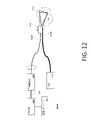
図1Aは、主題の実施形態の特徴のうちの1つまたは複数が実装され得る、内視鏡100などの、少なくとも第1の実施形態の図である(後述されるように、図1Bには、さらなる、または代替的実施形態が示されており、図1Cには、さらなる、または他の代替的実施形態が示されている)。内視鏡100は、広帯域光源102を含むか、またはそれに接続され得る。広帯域光源102は、複数の光源を含み得るか、または単一の光源であり得る。広帯域光源102は、レーザ、有機発光ダイオード(organic light emitting diode、OLED)、発光ダイオード(light emitting diode、LED)、ハロゲンランプ、白熱灯、レーザによってポンピングされるスーパーコンティニウム光源、および/または蛍光ランプのうちの1つまたは複数を含み得る。広帯域光源102は、空間情報のスペクトル符号化のために次に用いられる光を提供するために次に分散され得る光を提供する任意の光源であり得る。広帯域光源102は、内視鏡100の他の構成要素、または本明細書において説明される任意の他の実施形態(限定するものではないが、システム100’(図1B参照)、100’(図1C参照)などを含む)にファイバで結合され得るか、または自由空間で結合され得る。
FIG. 1A is a diagram of at least a first embodiment, such as an
内視鏡100は、回転接合部(rotary junction)106を含み得る。光源102と回転接合部106との間の接続は、自由空間結合、またはファイバ104を介したファイバ結合であり得る。回転接合部106は、回転結合を介して照明光のみを供給し得るか、あるいは照明光、電力、および/またはセンサ信号線(sensory signal line)のうちの1つまたは複数を供給し得る。
回転接合部106は、光を第1の導波路108に結合する。一実施形態では、第1の導波路108は、単一モードファイバ、多モードファイバ、または偏光保持ファイバである。
Rotating
第1の導波路108は、光学装置および/または光学系112に結合されている。光学装置および/または光学系112は、第1の導波路108からの光を屈折させ、反射し、分散させ、照明光のライン114をサンプル116上に形成する、1つまたは複数の光学構成要素を含み得る。一実施形態では、照明光のライン114は、照明光が光学装置および/または光学系112を出たときの波長範囲のための焦点をつないだラインであり、波長範囲は光源102によって決定される。別の実施形態では、分光計120は、対象の指定された波長からの情報のみを用いることによって、波長範囲をさらに限定し得る。別の実施形態では、照明光のライン114は、分光計120によって検出される波長の範囲にわたって照明光がサンプル116の表面と交差した際に照明光によって形成されるラインである。別の実施形態では、照明光のライン114は、検出光学部品によって決定される特定の画像平面上に形成される波長範囲内の照明光のラインである。1つまたは複数の実施形態では、画像ライン上の点の一部のみが合焦していてもよく、その一方で、画像ライン上の他の点は合焦していなくてもよい。照明光のライン114は直線状または曲線状であり得る。
代替的な一実施形態では、光学装置および/または光学系112は、光がサンプル116上に合焦されるが、回折格子などの分散光学要素においては光が実質的にコリメートされているよう、導波路108からの光を部分的にコリメートし得る。
In an alternative embodiment, the optics and/or
装置100は検出導波路118を含み得る。検出導波路118は、多モードファイバ、複数の多モードファイバ、ファイババンドル、ファイバテーパ(fiber taper)、または何らかの他の導波路であり得る。検出導波路118は、光学装置および/または光学系112からの光によって照明されたサンプル116からの光を集光する。検出導波路118によって集光される光は、反射光、散乱光、および/または蛍光であり得る。一実施形態では、検出導波路118は光学装置および/または光学系112の分散要素の前または後に配置され得る。一実施形態では、検出導波路118は、光学装置および/または光学系112の分散要素によって覆われていてもよく、この場合には、分散要素は波長-角度フィルタ(wavelength-angular filter)の役割を果たし得る。別の実施形態では、検出導波路118は、光学装置および/または光学系112の分散要素によって覆われていない。検出導波路118は、サンプル116からの検出光を分光計120へ導く。
分光計120は、光を分散させ、検出導波路118からの検出光を1つまたは複数の検出器へ導く1つまたは複数の光学構成要素を含み得る。1つまたは複数の検出器は、直線アレイ、電荷結合デバイス(charge-coupled device:CCD)、複数のフォトダイオード、または光を電気信号に変換する何らかの他の方法であり得る。分光計120は、プリズム、回折格子、またはグリズムなどの1つまたは複数の分散構成要素を含み得る。分光計120は、分光計120がサンプル116からの検出光の強度および波長を測定することを可能にする光学部品および光電子構成要素を含み得る。分光計120は、アナログ-デジタル変換器(analog to digital converter:ADC)を含み得る。
分光計120は、デジタルまたはアナログ信号を、限定するものではないが、画像プロセッサ122、またはプロセッサもしくはコンピュータ1300、1300’(例えば、図1B~図1C参照)、これらの組み合わせ等などの、プロセッサまたはコンピュータへ伝送し得る。画像プロセッサ122は、専用画像プロセッサ、または画像を処理するように構成された汎用プロセッサであり得る。少なくとも1つの実施形態では、コンピュータ1300、1300’が、画像プロセッサ122の代わりに用いられてもよい。代替的な一実施形態では、画像プロセッサ122は、ADCを含み、分光計120からのアナログ信号を受信し得る。画像プロセッサ122は、CPU、DSP、FPGA、ASIC、または何らかの他の処理回路機構のうちの1つまたは複数を含み得る。画像プロセッサ122は、画像、データ、および命令を記憶するためのメモリを含み得る。画像プロセッサ122は、分光計120によって提供された情報に基づいて1つまたは複数の画像を生成し得る。限定するものではないが、コンピュータ1300、コンピュータ1300’、画像プロセッサ122などの、本明細書において説明されるコンピュータまたはプロセッサは、また、本明細書で以下においてさらに説明される1つまたは複数の構成要素を含み得る(例えば、図31~図32参照)。
内視鏡100の1つまたは複数の構成要素は、照明光の2Dアレイを作り出すべく照明光のライン114を走査するために、回転接合部106を介して回転されるか、または振動されてもよい。光学装置および/または光学系112からのスペクトル符号化されたラインをサンプル116にわたって走査することによって、2D画像が形成され得る。内視鏡100は、検出ファイバ118からの光を分光計120に結合する追加の回転接合部を含み得る。代替的に、分光計120、または分光計120の一部分は、ファイバ118と共に回転し得る。代替的な一実施形態では、回転接合部106が存在せず、光源は、ファイバ108と共に回転する。代替的な一実施形態は、スペクトル符号化された照明光のラインを、2D画像を作成するために、スペクトル符号化された照明光のライン114と実質的に垂直に直線状に、またはトロイダル画像を作成するために円周方向に円状に、サンプル116にわたって回転させるか、または走査する光学構成要素(ミラー)を、光学系112内に分散要素の後に含み得る。実質的には(Substantially)、本開示の1つまたは複数の実施形態の文脈において、内視鏡100、システム100’、システム100’’および/または本明細書において説明される任意の他のシステムの整列および/または検出公差以内を意味する。代替的な一実施形態では、回転接合部106が存在せず、光学装置および/または光学系112の照明端部が、照明ラインと垂直な方向に走査されるか、または振動される。
One or more components of
図2は、光源102からの照明光を導くための第1の導波路108、検出光を集光するための第2の導波路118、および光学系112を含む前方ビューSEEの端部部分の図である。光学系112は、GRINレンズであり得るレンズ210を含み得る。光学系112は、また、第1の反射面228、第2の反射面230、および分散要素226(すなわち、回折格子)を含み得る。
FIG. 2 shows an end portion of the front view SEE including a
1つまたは複数の代替的実施形態では、図1Bおよび図1Cにそれぞれ示されるように、分散要素107(すなわち、回折格子)が光学装置および/または光学系112内で用いられ得る。1つまたは複数の実施形態(図1Bおよび図1Cにおいて最もうまく見られる)では、照明光ファイバまたは第1の導波路108の端部部分のコアから放射された光は、屈折率分布レンズ(以下、「屈折率勾配(gradient index)(GRIN)レンズ」と呼ばれる)109を介してスペーサ111に入ることができる(代替的に、1つまたは複数の実施形態では、図2のレンズ210がGRINレンズとして用いられてもよい)。回折格子107は、図1Bおよび図1Cに示されるように、スペーサ111の先端部分に形成され、回折格子107に入る白色光の光束によってスペクトル系列114が被検体またはサンプル116上に形成される。図1Cは、図1Bに示される分光計(例えば、システム100’を参照)を含むが、偏向または被偏向セクション(deflecting or deflected section)117が図1Bのシステム100’に組み込まれており、これにより、光源102を回転接合部106および/または光学装置および/または光学系112に接続するケーブルもしくはファイバ104および/またはケーブルもしくはファイバ108、ならびに分光計120を回転接合部106および/または光学装置および/または光学系112に接続するケーブルもしくはファイバ118が、被偏向セクション117(以下においてさらに説明される)を通過し、それを介して接続されている、SEEシステム100’’の代替的な一実施形態を示す。
In one or more alternative embodiments, a dispersive element 107 (ie, a diffraction grating) may be used within an optical device and/or
少なくとも1つの実施形態では、コンソールまたはコンピュータ1300、1300’が、運動制御ユニット(Motion Control Unit、MCU)140を介してRJ106の運動を制御するように動作し、分光計120内の検出器からの強度データを取得し、走査された画像を(例えば、さらに後述される図31のコンソール1300および/または図32のコンソール1300’内に示されるディスプレイ、スクリーンまたはモニタ1309などのモニタまたはスクリーン上に)表示する。1つまたは複数の実施形態では、MCU140は、RJ106のモータおよび/またはRJ106の速度を変更するように動作する。モータは、速度を制御し、位置精度を向上させるためのステッピングまたはDCサーボモータであり得る。1つまたは複数の実施形態では、偏向または被偏向セクション117は、光源からの光を干渉光学系へ偏向させ、その後、干渉光学系から受光された光を少なくとも1つの検出器に向けて送るように動作する構成要素としては、1つまたは複数の干渉計、サーキュレータ、ビームスプリッタ、アイソレータ、カプラ、溶融ファイバカプラ(fusion fiber coupler)、内部に孔を有する部分的に切断されたミラー(partially severed mirror)、およびタップを有する部分的に切断されたミラーのうちの少なくとも1つを含む偏向または被偏向セクションなどのうちの少なくとも1つであり得る。1つまたは複数の他の実施形態では、回転接合部106は、接触回転接合部、レンズのない回転接合部、レンズベースの回転接合部、または当業者に知られた他の回転接合部のうちの少なくとも1つであり得る。
In at least one embodiment, a console or
一実施形態では、第1の導波路108は、単一モードファイバであり得る。代替的な一実施形態では、第1の導波路108は、多モードファイバまたはダブルクラッドファイバであり得る。一実施形態では、第2の導波路118は、多モードファイバ、単一モードファイバ、またはファイババンドルであり得る。
In one embodiment,
代替的な一実施形態では、第1の導波路108は、ダブルクラッドファイバの内部コアであってもよく、その一方で、第2の導波路118は、内部コアとダブルクラッドファイバの外部クラッドとの間にあってもよい。ダブルクラッドファイバが用いられる場合には、代替的な一実施形態は、照明光を内部コアへ導くための光カプラを含み得るものであり、光カプラは、また、次に分光計120へ導かれる外部導波路からの検出光も受光し得る。
In an alternative embodiment, the
レンズ210は、第1の反射面228および第2の反射面230を含む光学構成要素の端部に取り付けられ得る。第1の反射面228は、内部全反射(total internal reflecting:TIR)面であり得る。第1の反射面228は、第1の導波路108の出力ポート232からの光を反射する表面であり得る。第1の導波路108の出力ポート232を出た光は、第1の反射面228によって反射される前にレンズ210を通過し得る。第1の反射面228および分散要素226は、実質的に同じ平面上にあり得るものであり、どちらも単一の支持構造224上にあり得る。第1の反射面228は、単一の支持構造224と、単一の支持構造224の光学特性とは異なる1つまたは複数の光学特性を有する第2の光学構造との間の境界面である。分散要素226は、第2の光学構造に結合され得る。分散要素226の平面は、第1の反射面228の平面と実質的に平行であり得る。分散要素226の平面は、狭いサブミクロンの間隙によって第1の反射面の平面から分離されていてもよい。第2の光学構造は、薄膜または薄層であり得る。
第1の反射面228は、TIRのための境界面を作り出す、回折格子と単一の支持構造224との間に存在する低屈折率材料(薄膜もしくは薄層)または空隙の間の境界面であり得る。低屈折率の薄膜または薄層の厚さは、以下の公式(1)で定義される厚さdよりも大きくなければならない。

式(1)において、λは、一実施形態では800nmであり得る、照明光の最も長い波長であり、θ1は、第1の反射面228の法線に対する照明光の入射角であり、n1(λ)は、波長λにおける単一の支持構造224の屈折率であり、n2(λ)は、波長λにおける第1の反射面228の反対側の屈折率であり、dは、単一の支持構造224との第1の反射面228の境界面を形成する薄膜または薄層334のための厚さのための下限である。一実施形態では、n1(λ)>n2(λ)である。厚さdのための通常の範囲は、30nm~500nmである。例えば、少なくとも一実施形態は、以下の条件を有し得る。n1(λ)は1.65であり、n2(λ)は1.4であり、θ1は60°である。波長λが400nmである場合には、このとき、dは111nmであり、波長λが800nmである場合には、このとき、dは222nmである。

第2の反射面230は、単一の支持構造224のTIR面またはミラーコーティング面であり得る。広帯域光源102からの光は、第1の導波路108を通り、レンズ210に入ってくる。光は、それが第1の反射面228に入射するときに、ほぼコリメートされている。レンズ210は、4分の1ピッチ、0.22ピッチ、または他のピッチのGRINレンズであり得る。第1の反射面228および第2の反射面230は、照明光が分散要素226(回折格子)によって分散される(回折される)前に、照明光を2回反射する。
The second
広帯域光源102は、異なる波長(λB1、λBi、...、λBN、λG1、λGi、...、λGN、λR1、λRi、...、λRN)を有する光を有し、(λB1<λBi<λBN<λG1<λGi<λGN<λR1<λRi<λRN)は、図2に示されるように、ライン114内のサンプル116上の異なる部位(X1、Xi、...、XN)上に回折される。ここで、B、G、およびRは、青色のための波長帯域、緑色のための波長帯域、および赤色のための波長帯域をそれぞれ表す。複数の回折次数の回折光を重ね合わせることによって、図2に示される照明光柱(illumination light column)114を形成することができる。例えば、青色のための波長帯域のためには、-6次光が用いられ、緑色のための波長帯域のためには、-5次光が用いられ、赤色のための波長帯域のためには、-4次光が用いられる。波長λjのうちの少なくとも1つは、ライン114とレンズ210の光軸との交点である点Xjへ平行に伝搬する。一実施形態では、Xj=X1である。
A
サンプル116から反射、散乱、または蛍光された光は、第2の導波路118によって集光され得るものであり、分光計120へ送られ得る。
Light reflected, scattered, or fluorescent from
SEEの1つまたは複数の構成要素は、サンプル116の2次元画像を取得するために運動または回転させることができる。一実施形態では、第1の導波路108、第2の導波路118、および光学系112は、回転または走査される。一実施形態では、第1の導波路108および光学系112は、回転または走査される。一実施形態では、光学系112は、回転または走査される。一実施形態では、レンズ210、第2の導波路118、および単一の支持構造224は、回転または走査される。一実施形態では、レンズ210および単一の支持構造224は、回転または走査される。一実施形態では、単一の支持構造224は、回転または走査される。一実施形態では、第2の導波路118および単一の支持構造224は、回転または走査される。
One or more components of the SEE can be moved or rotated to acquire a two-dimensional image of
内視鏡100の様々な構成要素のうちの1つまたは複数はレンズ210の光軸の周りに回転させることができる。一実施形態では、単一の支持構造224は、回転または走査されると、このとき、分散要素226、第1の反射面228、および第2の反射面230が単一の支持構造224と共に回転される。光学系の一部分を光軸の周りに回転させることは、内視鏡100がサンプルの2次元画像を取得することを可能にする。同様に、光学系の一部分を走査することは、内視鏡100が2次元画像を取得することを可能にする。これは、SEEが、1つの次元(x,r)が波長によって符号化され、その一方で、第2の次元(y,θ)が時間を用いて符号化された画像を得ることを可能にする。この光学設計は、小さな直径の前方ビューSEEプローブを可能にする。
One or more of the various components of
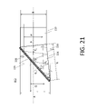
本開示の少なくとも第1の実施形態の一例は、0.1のNAを有する単一モードファイバを含む第1の導波路108を含み得る。第1の導波路108は、また、500umの長さを有する溶融シリカで作製されたコアレスファイバを含み得る。コアレスファイバは、長さ3.2mmを有するGRINレンズ210に結合され得る。単一の支持構造224は、1.65の屈折率n1を有し得、GRINレンズ210の端部に取り付けられ得る。図3は、単一の支持構造224上の薄膜または薄層334を含み、第1の反射面228を形成する、一実施形態の第1の例の一部分の図である。薄膜または薄層334は1.34の屈折率n2を有し得る。下式(2)は、本例については54.3°であるTIRのための臨界角θcriticalを算出するための式である。

図3に示されるように、反射構成要素334の第1の反射面228の法線と光軸との間の角度θ1は、一実施形態では、-58°である(この場合、角度は光軸から面法線へ反時計方向に回転し、このとき、符号は負であり、さもなければ、符号は正である)。一方で、第2の反射面230の法線とGRINレンズ210の光軸との間の角度θ2は、一実施形態では、92°である。一実施形態では、単一の支持構造224は、単一の支持構造224の表面のうちの1つがGRINレンズ210の光軸と垂直となるように配向された58-34-88プリズムである。別の実施形態では、GRINレンズ210は光軸に対して2°の角度で研磨されていてもよく、単一の支持構造224は、角度θ1によって、第1の表面が照明光のためのTIR表面になるよう、光軸に対して2°に配向された60-30-90プリズムであってもよい。一実施形態では、単一の支持構造224は、角度θ2が、TIRのゆえに第1の反射面228から反射された照明光の、第2の反射面230を通した後方反射を生じさせるように配向されている。別の実施形態では、単一の支持構造224の角度は、角度θ2が、TIRのゆえに第1の反射面228から反射された照明光の、第2の反射面230を通した後方反射を生じさせるように設計されている。
As shown in FIG. 3, the angle θ 1 between the normal to the first
別の実施形態では、単一の支持構造224の屈折率および薄膜334の屈折率は、単一の支持構造224が60-30-90プリズムであり、角度θ1によって、第1の表面が照明光のためのTIR表面になるように調整されてもよい。加えて、単一の支持構造224は、角度θ2が、TIRのゆえに第1の反射面228から反射された照明光の、第2の反射面230を通した後方反射を生じさせるように配向されている。別の実施形態では、単一の支持構造224の角度は、θ2が、TIRのゆえに第1の反射面228から反射された照明光の、第2の反射面230を通した後方反射を生じさせるように設計されている。
In another embodiment, the index of refraction of the
一実施形態では、分散要素226は、1379線/mmの溝密度を有する回折格子である。一実施形態では、第2の反射面230はミラーコーティング面である。一実施形態の作動距離は、約20mmである。少なくとも一実施形態では、作動距離は、スペクトル符号化されたライン114が被検体またはサンプル116上に合焦されたときの、分散要素226と被検体またはサンプル116との間の距離である。
In one embodiment,
本実施形態の1つの利点は、光学構成要素が光軸上に位置し、これにより、より容易な整列および組み立てが可能になることである。 One advantage of this embodiment is that the optical components are located on the optical axis, which allows for easier alignment and assembly.
図4は、図2に示される第1の実施形態と実質的に同様である代替的な(第2の)実施形態の一部分の図である。第2の実施形態では、第1の導波路108は、レンズ210の光軸に対して軸外においてレンズ210に取り付けられるか、または継ぎ合わせられ得る。図4に示されるように、第1の導波路108がレンズ210の光軸から離れて位置付けられると、このとき、照明光は、レンズ210の光軸に対して斜めにレンズ210を出て単一の支持構造224に入る。残りの構成要素は、第1の実施形態と実質的に同様である。
FIG. 4 is a partial view of an alternative (second) embodiment substantially similar to the first embodiment shown in FIG. In a second embodiment, the
図4に示されるように、第1の導波路108の軸外位置は、導波路からの中心(主)光線が第1の反射面228に入射する角度を変化させる。これは、中心光線に対して決定される内部全反射のための角度の決定に影響を与える。内部全反射のための角度は、第1の反射面228の法線に対する第1の導波路108からの主光線の入射角θ1に対して算出される。
As shown in FIG. 4, the off-axis position of
第2の実施形態の利点は、光が、第1の反射面228および分散要素226の有効径(光学部品の中心区域)の中心のより近くに入射するように案内されることである。第2の実施形態の別の利点は、それが、レンズ210の中心軸に対する第2の反射面230の角度の選定におけるより高い自由度を可能にすることである。第2の実施形態の別の利点は、第1の導波路108の位置を移動させることが、レンズ210の光軸に対する照明光のライン114の位置も移動させることである。
An advantage of the second embodiment is that the light is guided to be incident closer to the center of the effective diameter (the central area of the optic) of the first
図5は、図2に示される第1の実施形態と実質的に同様である代替的な一実施形態の一部分の図である。第3の実施形態は、図5に示されるように、デュアルビューまたは拡張ビューを有し得る。本実施形態では、(単一の支持構造224)/(分散要素226)境界面の一部分にのみ薄膜または薄層534(低屈折率材料)が適用される。これは、第1の導波路108からの照明光の第1の部分が回折格子226の第1の部分526aによって側方ビュー方向に向けて直接回折され、側方ビュースペクトル照明ライン514を形成することを可能にする。その一方で、第1の導波路108からの照明光の第2の部分は、第1の反射面528、次に、第2の反射面230によって反射され、第1の反射面528を通過し、次に、回折格子226の第2の部分526bによって前方ビュー方向に向けて回折される(例えば、照明ライン114を参照)。
FIG. 5 is a partial view of an alternative embodiment substantially similar to the first embodiment shown in FIG. A third embodiment can have a dual view or an extended view, as shown in FIG. In this embodiment, a thin film or layer 534 (low index material) is applied to only a portion of the (single support structure 224)/(dispersive element 226) interface. This is because a first portion of the illumination light from the
一実施形態では、薄膜または薄層534の厚さ(10~500nm)は、単一の回折格子226が分散要素226の第1の部分526aおよび回折格子/分散要素226の第2の部分526bの役割を果たすことができ、厚さの変動に起因するいかなる歪みも、単一の回折格子の機械的順応性に起因する光学装置および/または光学系112の照明能力への影響を最小限に抑えるようなものになっている。代替的な一実施形態では、第1の部分526aおよび第2の部分526bは、異なる回折格子である。代替的な一実施形態は、薄膜または薄層534と同じ厚さを有し、単一の支持構造224の屈折率と同じであるか、または同様である屈折率を有する、分散要素226の第1の部分526aの下の薄膜または薄層をさらに含み得る。代替的な一実施形態では、薄膜または薄層534の真下の単一の支持構造224の区域がそり落とされる(shaved down)。単一の支持構造224の区域は、エッチング、研磨、または光学材料を除去する他のよく知られた方法を用いることによってそり落とすことができる。
In one embodiment, the thickness of the thin film or layer 534 (10-500 nm) is such that the
前方ビュー(λ1、X1;λ2、X2;λ3、X3)に向けて回折される光は、回折格子226の第2の部分526bの-1回折次数である。側方ビュー(λ1、X4;λ2、X5;λ3、X6)に向けて回折される光は、回折格子226の第1の部分526aの+1回折次数であり得る。一実施形態では、回折格子526bは、波長の大部分の0次および+1次が回折格子526bを透過されないように設計されていてもよい。回折格子526bを透過される+1次の波長は、光が検出ファイバの受光角内に入らないように、大角度で回折されてもよい。一実施形態では、回折格子526aは、回折格子526aの-1次が回折格子526aを透過されないように設計されていてもよい。
The light diffracted towards the forward view (λ 1 , X 1 ; λ 2 , X 2 ; λ 3 , X 3 ) is the -1 diffraction order of the
透過回折格子は、光を回折するとともに、屈折もさせる。回折光は、回折次数(+1、-1など)に対応する。屈折光は、0次に対応する。回折格子に入射する光が、臨界角よりも大きい入射角を有する場合には、このとき、0次が回折格子を透過されず、その代わりに、TIRのゆえに反射されることが可能である。回折格子の設計パラメータは、それらの効率である。各次数(0次を含む)は光の波長ごとの特定の効率を有する。この効率は、照明角度、光の波長、偏光などの関数である。この効率は、回折格子のプロファイル、入射角、および材料特性を調整することによって制御され得る。例えば、プロファイルは、ブレーズド回折格子を作り出すように調整され得る。プロファイルは、また、溝密度、アスペクト比を制御することによって調整され得る。調整され得る材料特性のうちの1つは、回折格子の屈折率である。 A transmission grating diffracts and also refracts light. The diffracted light corresponds to the diffraction orders (+1, -1, etc.). The refracted light corresponds to the 0th order. If the light incident on the grating has an angle of incidence greater than the critical angle, then the 0th order may not be transmitted through the grating and instead be reflected due to TIR. A design parameter of diffraction gratings is their efficiency. Each order (including the 0th order) has a specific efficiency for each wavelength of light. This efficiency is a function of illumination angle, light wavelength, polarization, and so on. This efficiency can be controlled by adjusting the grating profile, angle of incidence, and material properties. For example, the profile can be tailored to create a blazed grating. The profile can also be adjusted by controlling groove density, aspect ratio. One of the material properties that can be adjusted is the refractive index of the grating.
一実施形態では、図5に示される実施形態における、使用されない0次および他の次数に関連付けられた両方の回折格子526aおよび526bの効率は、50%未満でなければならないか、あるいは40%、30%、20%、10%、5%、1%、または0.1%未満であり得る。1つまたは複数の検出ファイバの受光角を制限することで、0次光に関連付けられた光の量を低減することができる。代替的な一実施形態では、検出光の波長範囲は、回折格子526aおよび526bを出る際に0次光ビームと空間的に一致しない範囲に限定されてもよい。
In one embodiment, the efficiency of both
図6は、第1の検出導波路118および第2の検出導波路518が一実施形態においてどのように構成され得るのかについての図である。側方/前方ビュー信号は、少なくとも2つの検出導波路(118および518)ならびに2つの分光計を用いて別個に検出され得る。別の実施形態では、側方/前方ビュー信号は、少なくとも2つの検出導波路(118および518)を同じ分光計120と共に用いて別個に検出され得る。分光計120は、一度に検出導波路(118および518)のうちの一方のみからの光が分光計120によって検出されるよう、スイッチおよび/またはシャッタを含み得る。別の実施形態では、分光計120は、いくつかの光学構成要素が共有される多重入力分光計であり得る。例えば、分光計120は、例えば、直線アレイの代わりに共有CCDアレイを検出システムとして用いることによって、複数のファイバからの入力を並列処理するように設計され得る。一実施形態では、複数のファイバのうちからの異なる光ファイバは、回折格子またはプリズムなどの分散要素の異なる部分上に合焦され得る。次に、分散光は、CCDアレイによって検出され得る。例えば、CCDアレイの列のセットのうちの1つは1つのファイバのために用いられてもよく、その一方で、CCDアレイの列の第2のセットは、別のファイバのために用いられてもよい。
FIG. 6 is a diagram of how
側方検出導波路518は、側方ビューからの信号を収集し、その一方で、前方ビューからの光を収集しないよう、入力先端において角度研磨されており、回折格子226の第2の部分526aによって覆われていてもよい。前方検出導波路118は、前方ビューからの信号を収集するために、大きな開口数(Numerical Aperture、NA)(例えば、NA=0.66)を有し得る。一実施形態では、前方検出導波路118は、角度研磨されておらず、導波路の前方に回折格子が存在しない。前方検出導波路118のための入力は、回折格子226の第1の部分526aに対して、入力が、回折格子226の第1の部分526aによって分散された光を受光しないように位置付けられ得る。
The
これらの実施形態の1つの利点は、実質的に同様の光学設計が、回折格子の選択、および低屈折率の薄膜もしくは薄層の被覆次第で、前方ビュープローブ(図4)、デュアルビュープローブ(図6)、または側方ビュープローブのいずれかになり得ることである。側方ビュープローブは、それが薄膜または薄層334を含まないことを除いて、前方ビュープローブと実質的に同様であり得る。本開示の1つまたは複数の実施形態の別の利点は、視野が容易に拡張され得ることである。
One advantage of these embodiments is that substantially similar optical designs can be used for forward-view probes (Fig. 4), dual-view probes (Fig. 6), or a side view probe. The side-view probe can be substantially similar to the front-view probe except that it does not include the membrane or
本開示の第3の実施形態の一例は、0.1のNAを有する単一モードファイバを含む第1の導波路108を含み得る。第1の導波路108は、また、500umの長さを有する溶融シリカで作製されたコアレスファイバを含み得る。コアレスファイバは、3.3mmの長さを有するGRINレンズ210に結合され得る。単一の支持構造224は、1.65の屈折率n1を有し得るものであり、GRINレンズ210の端部に取り付けられ得る。薄膜または薄層534が、第1の反射面528を形成する単一の支持構造224の一部分上に含まれてもよい。薄膜は、1.34の屈折率n2を有し得る。上式(2)は、TIRのための臨界角θcriticalを54.3°として算出するための式である。
An example of a third embodiment of the present disclosure may include
図5に示されるように、反射構成要素534の第1の反射面528の法線と光軸との間の角度は-60°であり得る。一方で、第2の反射面230の法線と光軸との間の角度は、一実施形態では、92°であり得る。一実施形態では、単一の支持構造224は、単一の支持構造224の表面のうちの1つが光軸と垂直となるように配向された60-32-88プリズムであり得る。別の実施形態では、単一の支持構造224は、θ1がTIR表面になるよう、光軸に対して2°に配向された60-30-90プリズムであり得る。光軸に対する反射構成要素の角度は、回折格子の設計、および異なる入射角における回折格子の回折効率に応じて調整され得る。
As shown in FIG. 5, the angle between the normal to the first
一実施形態では、分散要素226は、1550線/mmの溝密度を有する回折格子である。一実施形態では、第2の反射面230は、ミラーコーティング面である。一実施形態の作動距離は、約20mmである。少なくとも一実施形態では、作動距離は、スペクトル符号化されたライン114が被検体またはサンプル116上に合焦されたときの、分散要素226と被検体またはサンプル116との間の距離である。
In one embodiment,
別の(第4の)実施形態では、側方ビュー/前方ビューからの検出信号を区別するために、偏光が用いられ得る。偏光された信号は、空間的または時間的な信号の分離を可能にする、偏光子、光スイッチ、ビームスプリッタ、および/または偏光ビームスプリッタのうちの1つまたは複数を用いて、分光計120によって独立して検出されてもよい。偏光された信号は、1つの偏光のみを各々受け入れる2つの分光計によって検出されてもよい。この場合には、異なるビューからの信号が同時に検出され得る。
In another (fourth) embodiment, polarization may be used to distinguish detected signals from side/front views. The polarized signals are transmitted by
一実施形態では、前方ビュー導波路118は、第1の偏光を有する検出光のみが前方ビュー導波路118によって受光されるよう、偏光子を含み得るものであり、その一方で、側方ビュー検出導波路518は、第2の偏光を有する検出光のみが側方ビュー導波路518によって受光されるよう、偏光子を含み得る。
In one embodiment, the front-
図7は、図2に示される第1の実施形態と実質的に同様である本開示の少なくとも第5の実施形態の一部分の図である。この第5の実施形態では、第2の表面は、傾斜した反射面230の代わりに、湾曲した反射面730である。第5の実施形態では、GRINレンズ210を合焦光学部品として用いる代わりに、凹面鏡730が代わりに用いられ得る。代替的な一実施形態では、凹面鏡730は、GRINレンズ210に加えて用いられてもよい。第1の導波路108からの光は、第1の導波路108の出力ポートからの光を第1の反射面228へ導くガラス柱を含む単一の支持構造724を通って伝搬し得る。光が単一の支持構造724を通過する際に、光は発散し、第1の反射面228の法線に対して第1の角度セットで第1の反射面に入射し得る。第1の角度セットはθcriticalよりも大きいものであり得る。次に、照明光は、凹面鏡の役割を果たす曲面730から反射され得る。次に、凹面鏡730からの照明光は、分散要素226を通過し得る。検出導波路118が、単一の支持構造724の隣に配置されていてもよく、大きなNAを有し得る。
7 is a diagram of a portion of at least a fifth embodiment of the present disclosure substantially similar to the first embodiment shown in FIG. 2; FIG. In this fifth embodiment, the second surface is curved
凹面鏡730は、融着接続機を用いてボールレンズを形成し、次に、ミラーコーティングをボール表面に適用することによって作製され得る。湾曲した反射面730の半径は、回折格子に入射する光が実質的にコリメートされ、それゆえ、光が第1の導波路108を出る際の光の発散を補償し、その一方で、光をスペクトルライン714上になおも合焦させるようなものであり得る。
図8は、図7に示される第1の実施形態と実質的に同様である代替的な(第6の)実施形態の一部分の図である。この第6の実施形態は、より長い作動距離を有するように設計され得る。凹面鏡830は、楕円形状であり、2つの焦点を有し得る。第1の導波路108からの光は、第1の反射面228にも近接するか、またはそれと交差し得る楕円形状反射面830の第1の焦点に近接した中間焦点を有するGRINレンズ810を通って伝搬し得る。第1の導波路108は、また、500umの長さを有する溶融シリカで作製されたコアレスファイバを含み得る。GRINレンズ810は、照明光が単一の支持構造824を通って第1の反射面228上に合焦されるよう、0.42前後のピッチを有し得る。
FIG. 8 is a partial view of an alternative (sixth) embodiment substantially similar to the first embodiment shown in FIG. This sixth embodiment can be designed to have a longer working distance.
照明光が内部全反射のゆえに第1の反射面228から反射された後に、照明光は、第2の反射面830に向けて案内される。第2の反射面830は、楕円鏡である。照明光は、第2の反射面830から反射され、第1の反射面228を通過し、分散要素226によって分散され得る。
After the illumination light is reflected from the first
分散要素226は、第2の反射面830の楕円鏡の第2の焦点と一致するスペクトルライン814に沿って光を回折し得る。
GRINレンズ810は、照明光を第1の反射面228上に合焦させる。それゆえ、照明光は、GRINレンズ810のNAの関数である或る範囲の角度で第1の反射面228に入射する。第1の反射面228は、GRINレンズ810からの照明光の円錐に対して一部または全ての波長において内部全反射が生じるよう、照明光の最小入射角がθcriticalよりも大きくなるように配向されている。代替的な一実施形態では、第1の導波路108は、第1の反射面228上への照明光の入射角を調整するために、GRINレンズ810の光軸から離れるよう移動されてもよい。
第6の実施形態の一例は、0.1のNAを有する単一モードファイバを含む第1の導波路108を含み得る。第1の導波路108は、また、長さ500umを有する溶融シリカで作製されたコアレスファイバを含み得る。コアレスファイバは、長さ6.3mmを有するGRINレンズ810に結合され得る。
An example sixth embodiment may include a
GRINレンズ810は、1.65の屈折率を有する単一の支持構造824に結合され得る。単一の支持構造824の一部分は、楕円球の形状を取り得る。単一の支持構造824は、第1の反射面228のための境界面を作り出すように角度研磨され得る。単一の支持構造の研磨面の法線は、GRINレンズ810の光軸と、または主光線が光軸と整列していない場合には、導波路108からの照明光の主光線と、角度θ1=-58°をなし得る。単一の支持構造の研磨面は、また、単一の支持構造824の楕円球の焦点のうちの1つとも交差し得る。1.34の屈折率を有する薄膜または薄層334は、単一の支持構造824の研磨面に適用され、かくして、第1の反射面228のための境界面を形成してもよい。一実施形態では、TIRのための臨界角θcriticalは、54.3°である。一実施形態では、回折格子226の溝密度は、1379線/mmであり得る。
ミラーコーティングが単一の支持構造824の楕円球部分に適用されてもよく、かくして、第1の反射面228から回折格子226を通り抜けるよう光を反射する第2の反射面830をもたらす。回折格子226は、回折格子226の-1の回折次数に従って照明光を前方ビュー(λ1、X1;λ2、X2;λ3、X3)に向けて回折する。
A mirror coating may be applied to the elliptical spherical portion of the
第6の実施形態の一例では、単一の支持構造824の楕円球部分は、0.3mmの曲率および-0.4の円錐定数を有し得る。
In one example of the sixth embodiment, the elliptical spherical portion of the
図9は、実施形態が前方ビュー設計とは対照的に後方ビュー設計であることを除いて、図4に示される第2の実施形態と実質的に同様である代替的な(第7の)実施形態の一部分の図である。この第7の実施形態では、第1の導波路108は、レンズ210の光軸に対して軸外において取り付けられるか、または継ぎ合わせられ得る。
Figure 9 shows an alternative (seventh) embodiment substantially similar to the second embodiment shown in Figure 4, except that the embodiment is a rear view design as opposed to a front view design. FIG. 3 is a diagram of a portion of an embodiment; In this seventh embodiment, the
軸外の第1の導波路108からの照明光は、GRINレンズ210を通って伝搬する。GRINレンズ210を通って伝搬した後に照明光は、単一の支持構造924に入る。単一の支持構造は、3つの表面、第1の反射面928、第2の反射面930、および分散要素226が取り付けられた第3の表面を含み得る。
Illumination light from off-axis
第1の反射面928は、GRINレンズ210および支持構造924を通って伝搬してきた照明光を反射し得る。第1の反射面928は、TIRのゆえに、または第1の反射面928上の反射フィルムもしくは層のゆえに照明光を反射し得る。第2の反射面930は、第1の反射面928からの照明光を反射し得る。第2の反射面930は、TIRのゆえに、または第2の反射面930上の反射フィルムもしくは層のゆえに照明光を反射し得る。第2の反射面930は、第1の反射面928からの照明光を、その光が分散要素226を通って伝搬するように反射し得る。
First
分散要素226は、光を-1の回折次数に沿ってスペクトルライン914上へ分散させる透過型回折格子であり得る。後方ビュー内視鏡は、撮像される表面が多数のひだを有し得る結腸鏡検査などにおいて、撮像される被検体の表面の複雑さに応じて有用になり得る。
図10A~図10Bは、実施形態が後方ビューおよび側方ビューを含むことを除いて、図9および図5にそれぞれ示される第7の実施形態および第3の実施形態の組み合わせと実質的に同様である代替的な(第8の)実施形態の一部分の図である。第8の実施形態は、2つの回折格子1026aおよび1026bを含み得る。一実施形態では、第1の導波路108からの光はGRINレンズ210を通って伝搬する。第1の導波路は、GRINレンズ210の中心軸から軸外に位置付けられ得る。GRINレンズ210を通って伝搬した後に照明光は、単一の支持構造1024に入る。次に、照明光は、第1の反射面928から反射され得る。一実施形態では、第1の反射面928からの反射は、TIRによるものであり、別の実施形態では、第1の反射面からの反射は、第1の反射面928上のミラーコーティングによるものである。
Figures 10A-10B are substantially similar to the combination of the seventh and third embodiments shown in Figures 9 and 5, respectively, except that the embodiments include rear and side views. FIG. 12 is a diagram of a portion of an alternative (eighth) embodiment in which FIG. An eighth embodiment may include two
後方ビュー伝搬モードでは、第1の反射面928から反射した照明光は、第2の反射面1030から反射され、回折格子であり得る第1の分散デバイス1026aを通って伝搬し、照明ライン1014aを形成し得る。第2の反射面1030によって反射される光は、TIRのゆえに反射されてもよい。第2の反射面1030は、単一構造1024上の薄膜または薄層から形成されていてもよい。
In the rear-view propagation mode, illumination light reflected from first
側方ビュー伝搬モードでは、第1の反射面928から反射した照明光は、回折格子であり得る第2の分散デバイス1026bを通って伝搬する。側方ビュー伝搬モードでは、第2の反射面1030に対する照明光の入射角が臨界角よりも小さいため、内部全反射が表面1030上で生じない。図10Bに示されるように、臨界角よりも大きい角度で第2の反射面1030に入射する光は、第2の反射面1030から第1の分散デバイス1026aに向けて反射される。その一方で、臨界角よりも小さい角度で第2の反射面1030に入射する光は、第2の反射面1030を通過し、次に回折され、第2の照明ライン1014bを形成する第2の分散デバイス1026bに入射する。
In the side-view propagation mode, illumination light reflected from the first
側方/後方ビュー信号は、少なくとも2つの検出導波路および2つの分光計を用いて別個に検出され得る。別の実施形態では、側方/後方ビュー信号は、少なくとも2つの検出導波路を同じ分光計120と共に用いて別個に検出され得る。分光計120は、検出導波路のうちの一方のみからの光が分光計120によって検出されるよう、スイッチおよび/またはシャッタを含み得る。別の実施形態では、分光計120は、いくつかの光学構成要素が共有される多重入力分光計であり得る。例えば、分光計120は、例えば、直線アレイの代わりに共有CCDアレイを検出システムとして用いることによって、複数のファイバからの入力を並列処理するように設計され得る。
Side/back view signals can be detected separately using at least two detection waveguides and two spectrometers. In another embodiment, the side/rear view signals can be detected separately using at least two detection waveguides with the
検出導波路は、照明光学部品の隣に位置し得る。検出導波路は、ファイバへの信号のうちの全てが必ずしも照明光学部品によって遮断されていないようなものであり得る。後方ビューからの信号を検出するために、後方ビュー信号が、後方ビューに関連付けられた検出導波路の受光NA(acceptance NA)内に案内されるよう、検出ファイバの前方に反射、回折、および/または散乱光学部品が存在してもよい。 A detection waveguide may be located next to the illumination optics. The detection waveguide can be such that not all of the signal to the fiber is blocked by the illumination optics. In order to detect signals from the rear view, the rear view signal is reflected, diffracted, and/or reflected in front of the detection fiber so that it is guided within the acceptance NA of the detection waveguide associated with the rear view. Or there may be scattering optics.
側方ビューからの信号を検出するために、検出導波路のうちの少なくとも1つは入力において角度研磨されており、側方ビューからの信号を収集し、その一方で、後方ビューからの光を検出しないよう、回折格子によって覆われていてもよい。反射光学部品、および検出ファイバのNAは、2つの異なるビューからの信号間のクロストークが、低減または解消され得るように設計され得る。 To detect signals from the side view, at least one of the detection waveguides is angle-polished at the input to collect the signal from the side view while transmitting light from the rear view. It may be covered by a diffraction grating so as not to be detected. The reflective optics and NA of the detection fiber can be designed such that crosstalk between signals from two different views can be reduced or eliminated.
図11は、GRINレンズを合焦光学要素として用いる代わりに、ボールまたはハーフボールレンズが用いられ得ることを除いて、図4に示される第2の実施形態と実質的に同様である代替的な(第9の)実施形態の一部分の図である。 Figure 11 is an alternative embodiment substantially similar to the second embodiment shown in Figure 4, except that instead of using a GRIN lens as the focusing optic, a ball or half-ball lens can be used. Fig. 11 is a view of a portion of a (ninth) embodiment;
第1の導波路108からの照明光は、スペーサ1136を通って伝搬し得る。スペーサの屈折率は、第1の導波路108のコアの屈折率と実質的に一致し得る。スペース1136を通過した後に、照明光は、スペーサ1136の端部に取り付けられたハーフボールレンズ1138によって合焦され得る。ハーフボールレンズ1138を通過した後に、照明光はコリメートされ、光が単一の支持構造1124に入る際に若干合焦される。
Illumination light from
ボールレンズを通過した後の照明光は、単一の支持構造1124の第1の反射面228から反射される。単一の支持構造1124は、UV硬化樹脂またはエポキシで作製され得る。照明光は、TIRのゆえに第1の反射面から反射する。次に、照明光は、単一の支持構造1124を逆に通過し、次に、単一の支持構造1124の第2の反射面230から再び反射される。第2の反射面230は、研磨された平らな表面であってもよく、ミラーコーティングを有してもよい。代替的な一実施形態では、第2の反射面230は、ミラーコーティングを有しなくてもよく、TIRのゆえに照明光を反射してもよい。第2の反射面230によって反射された後に、照明光は、単一の支持構造1124を逆に通過し、今回は第1の反射面228を通過し、回折格子であり得る分散要素226によって分散される。
After passing through the ball lens, the illumination light is reflected from the first
一実施形態では、ボールレンズ1138は、融着接続機を用いてスペーサ1136から形成されてもよい。一実施形態では、検出導波路118は、スペーサ1136の隣に配置可能であり得るものであり、大きなNAを有し得る。
In one embodiment,
図12は、図1に示される第1の実施形態と実質的に同様である第10の実施形態1200の図である。第10の実施形態1200は、広帯域光源102を含むか、またはそれに接続され得る。広帯域光源102は、第2の導波路118と実質的に同様である第1の導波路1208に接続され得る。第10の実施形態では、第1の導波路1208は、多モードファイバであり得る。第1の導波路1208は、100μm、200μm、または400μmの直径を有するコアを有し得る。第1の導波路1208は、サンプル116を照明光1214で照明するために用いられ得る。
FIG. 12 is a diagram of a
サンプル116に入射した光を集光し、スペクトル符号化するための光学装置および/または光学系1212が用いられ得る。光学系1212(スペクトル符号化されたチャネル)は撮像チャネルとして用いられてもよく、その一方で、第1の導波路1208は、サンプル116を広帯域光で照明するための別個の照明チャネルとして用いられてもよい。広帯域光は、非干渉性であり得る。光学系1212は、検出導波路1218に結合され得る。検出導波路1218は、回転接合部106に接続され得る。回転接合部106は、ファイバ104に接続され得る。回転接合部106は、ファイバ104が静止した状態を維持しつつ、検出導波路1218ならびに光学装置および/または光学系1212が回転することを可能にし得る。ファイバ104は、上述された分光計120に接続され得る。分光計120は、上述された画像プロセッサ122(および/または上述された、もしくはさらに後述されるコンピュータ1300、1300’)に接続され得る。
Optics and/or
図13は、光学装置および/または光学系112と実質的に同様である光学装置および/または光学系1212の図である。上述されたように、第1の導波路1208は、サンプル116を照明する。光学装置および/または光学系1212は光を集光する。集光された光は、分散要素226を介して光学装置および/または光学系1212に入る。分散要素226は、光を回折する。光は、第1の反射面228を通過し、単一の支持構造224を通過し、第2の反射面230から反射され、第1の反射面228からTIRを介して、集光された光を検出導波路1218上に合焦させるレンズ210に向けて反射される。
FIG. 13 is a diagram of an optical device and/or
検出導波路1218は、開口の役割を果たし、特定の範囲の角度のみを受け入れる。回折格子は、特定の角度で光学系1212に入る特定の波長を有する光のみが、光学系1212を通過した後に検出導波路1218によって受け入れられることになることを確実にする。これにより、特定の部位(X1、Xi、...、XN)が特定の波長(λ1、λi、...、λN)を用いて符号化される。それゆえ、分光計120によって復号することができるスペクトル符号化された信号が提供される。
The
図14および表1に、レンズ210、支持構造224、および分散要素226を有する光学系112を含む、本開示の少なくとも第11の実施形態の詳細が示される。本実施形態では、支持構造として、高い屈折率を有するガラス材料を用いる設計の一例が与えられる。

図15(a)では、GRINレンズがレンズ210として用いられる。GRINレンズの端面は、8度の角度にカットされている。端面のこの角度は、反射によって生み出される戻り光の量を低減するのに効果的である。GRINレンズによって実質的に平行な光になった光(実際には、GRINレンズの長さは、サンプルの付近で合焦されるように調整されている)は、レンズ-支持構造ジョイント面234に角度θ1で入射し、角度θ2で屈折させられる。GRINレンズ210の光軸上の屈折率n0は1.48と等しく、それに対して、支持構造224の屈折率はおよそ2.05である。したがって、θ1>θ2であり、GRINレンズの光軸からの傾斜は、θ1-θ2の角度になる。屈折光は、第1の反射面228に角度θ3で入射する。第1の反射面228に角度θ3で入射する光が内部全反射されるよう、θ3が臨界角θcriticalよりも大きくなるために、支持構造224の屈折率および薄層324の屈折率が選択され、支持構造224の寸法が決定される。GRINレンズの端面が斜めにカットされていない場合と比べて、第1の反射面228に対する入射角θ3は、θ1-θ2だけより大きく、これにより、光は内部全反射される可能性が高くなる。すなわち、これは、支持構造224のものよりも低い屈折率を有するガラス材料の使用を可能にする効果を有する。図15(b)に示されるように、本実施形態では、分散要素226は回折格子であり、薄層324は、溝を有しない回折格子を形成する部材の領域に対応する。内部全反射角(臨界角)は、上記の公式(2)を用いることによって算出される。
In FIG. 15( a ), a GRIN lens is used as
第2の反射面230は、内部全反射された光の入射角θ4に対して高い反射率を有するためにコーティングされている。内部全反射された光が第2の反射面230によって反射された後に、光は、第1の反射面に角度θ5で再び入射する。角度θ5が臨界角θcriticalよりも小さくなるために、支持構造224の屈折率および薄層334の屈折率が選択され、支持構造224の寸法が決定される。図15(c)に示されるように、第1の反射面228に角度θ5で入射した光は、薄層を有する境界面において屈折させられ、角度θ6で透過される。回折格子226に角度θ6で入射した光は、その波長に応じて異なる角度θ7で回折される。
The second
αおよびβは、支持構造224のガラスプリズムの頂角を表す。γは、GRINレンズの光軸に対する第2の反射面230の傾斜を表す。
α and β represent the apex angles of the glass prisms of


本実施形態では、青色のための波長帯域のためには、-6次光が用いられ、緑色のための波長帯域のためには、-5次光が用いられ、赤色のための波長帯域のためには、-4次光が用いられる。回折角度が分散要素に対する入射角から算出される際に、プローブの前面に存在し、図14における部位Xjを照明する光の波長は、青色には416nm、緑色には498nm、および赤色には622nmである。他方で、内視鏡100の半画角が27.5度であるときには、部位XNを照明する光の波長は、青色には475nm、緑色には569nm、および赤色には710nmである。すなわち、第2の導波路118を用いることによって検出される光は、416nm~475nmの波長帯域を有する青色、498nm~569nmの波長帯域を有する緑色、および622nm~710nmの波長帯域を有する赤色にスペクトル分散しており、これにより、サンプル116上のX1~XNについての情報が得られる。
In this embodiment, the -6th order light is used for the wavelength band for blue, the -5th order light is used for the wavelength band for green, and the wavelength band for red is used. For this purpose, -4th order light is used. The wavelengths of light present in front of the probe and illuminating site Xj in FIG. 14 are 416 nm for blue, 498 nm for green, and 622 nm for red, when the diffraction angle is calculated from the angle of incidence on the dispersive element. is. On the other hand, when the half angle of view of
図16は、電磁場解析を用いることによって、上述された波長範囲内において高い回折効率を有するように設計された、回折格子226の回折効率を示す。表1におけるθ6に対応する、回折格子内の光ビームの伝搬角度は36°である。本開示の少なくとも本主題の実施形態において用いられる、-6次光、-5次光、および-4次光の回折効率は、上述された波長帯域内において高い値である。表2に、今回の回折格子226のパラメータが示される。例えば、回折格子226は、例えば、一方向に周期的に形成された溝を設けられた樹脂で作製されている。デューティ比は、溝の領域(回折格子を形成する材料が存在しない領域)の比率である。

図17は、3つの平面を形成するように柱をカットすることによって、第1の反射面228、第2の反射面230、およびレンズ-支持構造ジョイント面が形成された支持構造224の概略図である。
FIG. 17 is a schematic illustration of a
図15(a)と同様に、図18は、光軸(図14におけるXjの方向)を含む断面内で見たときの、図17における支持構造224の概略図である。θ1~θ7、α、β、およびγは、図15(a)および表1におけるものと同じである。スペクトル分散方向における有効光ビーム径がPであり、回折格子からの出射光ビーム径がQであるとき、光ビーム径の縮小比は、Q/Pによって表される。
Similar to FIG. 15(a), FIG. 18 is a schematic view of
図19において、図17における支持構造224が光軸(図14におけるXjの方向)から見られた概略図において、y方向は、スペクトル分散が回折格子226において生じる方向であり、x方向は、図14の平面と垂直である方向である。1つまたは複数の実施形態では、支持構造224が回転されたときの外接円は、支持構造224が回転されたと仮定すると、支持構造の縁部と接する「包絡円」である。
In FIG. 19, in a schematic view of
表3は、φ250μmのGRINレンズが用いられるときの支持構造224の寸法および出射光ビームのサイズを示す。

本開示の1つまたは複数の実施形態は、第1の反射面228を内部全反射面として用い、この場合も先と同様に、光が入射する透過面が、支持構造224のサイズが、GRINレンズの0.25mmのサイズとあまり異ならない0.33mmに低減されることを可能にする。加えて、要素の長さLが0.341mmの小さい値であるため、プローブの端部が容易に曲げられ、内視鏡の視野が広げられるという利点がある。さらに、γが、設計のために小さい5.2°であるため、支持構造224の寸法は、GRINレンズの直径と実質的に同等である、およそ0.28mm以内である。
One or more embodiments of the present disclosure use the first
本開示の1つまたは複数の実施形態では、スペクトル分散方向(y方向)における出射光ビーム径の縮小比(Q/P)が著しく劣化しないため、スペクトル分散能力(spectral dispersion capability)(サンプル116上に集められるスポットのサイズ)は著しく劣化しない。本実施形態では、第1の反射面228を広くすることができるため、レプリカ成形などの、回折格子の製作が容易になる。
In one or more embodiments of the present disclosure, spectral dispersion capability ( The size of the spot collected at ) is not significantly degraded. In this embodiment, since the first reflecting
2次元画像を得るために光学装置および/または光学系112が回転される際の回転中心は、図における224の外接円の中心である(図19参照)。回転中心と出射光ビームとの間の変位Fは10ミクロン以下であり、小さい。この偏心は、図14におけるXjが回転角度ごとに変化し、その結果、2次元画像内に乱れが生じるというものである。通常は、画像プロセッサにおいて、この偏心は、補正される必要がある。しかし、本開示の1つまたは複数の実施形態では、偏心が小さいため、偏心を補正する必要がない(本開示の1つまたは複数の他の実施形態では、偏心は、後述されるコンピュータ1300、1300’などの、画像プロセッサおよび/またはコンピュータによって補正されてもよい)。偏心が補正されなくてもよいそれらの実施形態のためには、光学装置および/または光学系112が回転されたときに、回転中心と出射光ビームとの間の変位Fは、外接円の直径Dの1/10以下であるであることが望ましい。
The center of rotation when the optical device and/or
図20ならびに表4および表5を用いることによって、第12の実施形態を説明する。説明は、少なくとも第11の実施形態に係るものと異なる部分の説明に限定される。第12の実施形態は、少なくとも第11の実施形態におけるものよりも低い屈折率を有するガラス材料が用いられるときの、支持構造224および回折格子226の設計の一例である。ガラス材料の屈折率は、2.0である。回折格子226に対する入射角θ6は、33°であり、第11の実施形態におけるものよりも若干小さく、回折格子は、627線/mmの回折格子である。図20は、第12の実施形態の特徴的構造である、光学系112を示す。表4に、屈折率、光ビーム角度、支持構造224の角度、および回折格子の回折格子定数が示される。

表5は、φ250ミクロンのGRINレンズが用いられるときの支持構造224の寸法および出射光ビームのサイズを示す。表5内の項目は、図19および図20におけるものに対応する。より高い屈折率を有するガラス材料が用いられる第11の実施形態と比べて、回折格子に対する入射光ビーム径(ビーム整形比(beam shaping ratio))は、若干より小さく、その結果、撮像性能は若干劣化する。

図21ならびに表6および表7を用いることによって、少なくとも第13の実施形態を説明する。説明は、第11の実施形態に係るものと異なる部分の説明に限定される。第13の実施形態では、GRINレンズの端面のカット角が5.57°に変更され、スペーサの角度βが直角であり、これにより、スペーサの処理コストが低減されることを可能にする構造がもたらされる。回折格子226に対する入射角θ6、および回折格子の線/mmは、第12の実施形態に係るものと同じである。図21は、第13の実施形態の特徴的構造である、光学系112を示す。表6は、屈折率、光ビーム角度、支持構造224の角度、および回折格子の回折格子定数を示す。

表7は、φ250ミクロンのGRINレンズが用いられるときの支持構造224の寸法および出射光ビームのサイズを示す。表7内の項目は、図19および図21におけるものに対応する。

図22ならびに表8および表9を用いることによって、第14の実施形態を説明する。説明は、第11の実施形態に係るものと異なる部分の説明に限定される。第14の実施形態は、第11の実施形態におけるものよりも高い屈折率を有するガラス材料が用いられるときの、支持構造224および回折格子226の設計の一例である。ガラス材料の屈折率は、2.1である。さらに、GRINレンズの端面内にカットが存在せず(0°)、GRINレンズの処理ステップの数が低減される。高い屈折率を有するガラス材料の影響のゆえに、短波長端におけるスペーサの透過率は、若干より低い。図22は、第14の実施形態の特徴的構造である、光学系112を示す。表8は、屈折率、光ビーム角度、支持構造224の角度、および回折格子の回折格子定数を示す。

表9は、φ250ミクロンのGRINレンズが用いられるときの支持構造224の寸法および出射光ビームのサイズを示す。表9内の項目は、図18におけるものに対応する。要素の長さLは、以前の実施形態におけるものよりも小さく、プローブの端部部分がより容易に曲げられることを可能にする構造がもたらされる。

図23ならびに表10および表11を用いることによって、第15の実施形態を説明する。説明は、少なくとも第11の実施形態のものと異なる部分の説明に限定される。第15の実施形態では、1つまたは複数の実施形態では、支持構造224のガラス材料のために(高屈折率ガラスではなく)石英を用い、表面228への最初の入射時に内部全反射を依然として有するために、空隙が支持材料224の隣の薄層334として用いられる。1つまたは複数の実施形態では、空隙334は、カバーガラスの周辺部に位置付けられた支持材料上のスペーサまたは突起部、あるいは光学部品(図示せず)の周辺部における環状または長円形スペーサによって形成され、維持され得る。代替的に、遠位光学部品のためのマウントが、取り付け時に空隙334のための空間を維持するために、内部に段または隆起を有するように作製されていてもよい。加えて、本実施形態では、回折格子226を支持するために、50ミクロンの厚さを有するカバーガラス336(石英製)が用いられる。カバーガラス336と支持構造224との間に空隙の薄層334が存在する。繰り返しの干渉の効果が生じるのを防止し、要素の高さを抑制するために、空隙は、照明光の波長の数倍~数十倍であるサイズを有する。より具体的には、それは、好ましくは、およそ5μm~20μmである。さらに、GRINレンズ210の端面上に追加の角度研磨が存在せず(0°)、GRINレンズの処理ステップの数が低減される。さらに、支持構造224は直角プリズムであることができ、低コストの生産に適している。回折格子226に対する入射角θ6は37°であり、第11の実施形態におけるものよりも若干大きく、回折格子は658線/mmの回折格子である。図23は、第15の実施形態の特徴的構造である、光学系112を示す。表10は、屈折率、光ビーム角度、支持構造224の角度、および回折格子の回折格子定数を示す。1つまたは複数の実施形態では、空隙、ガラスカバー、および/または薄層に加えて、(例えば、図23、後述される図25などに示される)回折格子226は、溝の層のみであり得るか、あるいは回折格子226は、回折格子および同じ材料の下層であり得る。
The fifteenth embodiment is described by using FIG. 23 and Tables 10 and 11. FIG. The description is limited to at least those parts that differ from those of the eleventh embodiment. In a fifteenth embodiment, one or more embodiments use quartz (rather than high-index glass) for the glass material of


図24において、図22における支持構造224が光軸(図14におけるXjの方向)から見られた概略図において、図におけるy方向は、スペクトル分散が回折格子226において生じる方向であり、図におけるx方向は、図14の平面と垂直である方向である。表は、φ250μmのGRINレンズが用いられるときの支持構造224の寸法および出射光ビームのサイズを示す。1つまたは複数の実施形態では、支持構造224が回転されたときの外接円は、支持構造224が回転されたと仮定すると、支持構造の縁部と接する「包絡円」である(図24参照)。
In FIG. 24, the
表11は、φ250ミクロンのGRINレンズが用いられるときの支持構造224の寸法および出射光ビームのサイズを示す。表11内の項目は、図23および図24におけるものに対応する。要素の長さLが305ミクロンであり、要素がコンパクトであるが、カバーガラスが必要とされる。したがって、要素の高さDが増大し、支持構造の外径Dはおよそ380μmになる。4つの角部を面取りすることによって、外径を若干低減することが可能である。本実施形態では、スペクトル分散方向(y方向)における出射光ビーム径の縮小比(Q/P)がおよそ0.87であり、大きいため、スペクトル分散能力(サンプル116上に集められるスポットのサイズ)の劣化を最小限にとどめることが可能である。

図25および図26(a)~(b)ならびに表12および表13を用いることによって、第16の実施形態を説明する。説明は、第11の実施形態に係るものと異なる部分の説明に限定される。第16の実施形態では、(例えば、特許第5,686,604号に記載されている)シリカベースの中空微細粒子を含有する材料を薄層338として用いることによって、支持構造224のガラス材料は、1.72の屈折率を有するガラス材料である。この場合には、回折格子226を薄層338上に形成することができるため、第15の実施形態におけるものとしてのカバーガラスは、必要とされない。図25は、第16の実施形態の特徴的構造である、光学系112を示す。上述されたように、1つまたは複数の実施形態では、空隙、ガラスカバー、および/または薄層に加えて、(例えば、図23、図25などに示される)回折格子226は、溝の層のみであり得るか、あるいは回折格子226は、回折格子および同じ材料の下層であり得る。図26(a)~(b)は、シリカベースの中空微細粒子を含有する低屈折率層(薄層338)の拡大図である。シリカベースの中空微細粒子を含有する低屈折率層の厚さは、波長よりも十分に大きい、およそ5μmである必要がある。図26(a)は、第1の反射面228において、レンズ210から放射された光の内部全反射を示す。図26(b)は、第2の反射面230を介して第1の反射面228に再び入射する光の屈折/透過を示す。表12は、屈折率、光ビーム角度、支持構造224の角度、および回折格子の回折格子定数を示す。

表13は、φ250ミクロンのGRINレンズが用いられるときの支持構造224の寸法および出射光ビームのサイズを示す。表13内の項目は、図19および図25におけるものに対応する。本実施形態では、支持構造は、およそ320ミクロンの外径Dを有し、非常にコンパクトであり、これにより、支持構造は、小さい直径を有する内視鏡としての使用に適している。

図27および図28ならびに表14および表15を用いることによって、第17の実施形態を説明する。説明は、第11の実施形態に係るものと異なる部分の説明に限定される。第17の実施形態では、GRINレンズの端面のカット角は、0°であり、スペーサの角度βは直角である。さらに、図28に示されるように、支持構造224は、直方体が第1の反射面228において2つに切断された形態を有し、さらに、本実施形態では、支持構造ジョイント面234は、正方形形状を有する。このように、単純な形態を有する支持構造224を形成することによって、処理コストを低減するだけでなく、製作誤差を低減し、安定した品質(回折効率および使用される波長帯域)をもたらすことも可能である。
27 and 28 and Tables 14 and 15 are used to describe the seventeenth embodiment. The description is limited to the description of the parts that are different from those related to the eleventh embodiment. In the seventeenth embodiment, the cut angle of the end face of the GRIN lens is 0° and the spacer angle β is a right angle. Further, as shown in FIG. 28, the
図27は、第17の実施形態の特徴的構造である、光学系112を示す。表14は、屈折率、光ビーム角度、支持構造224の角度、および回折格子の回折格子定数を示す。本実施形態では、以前の実施形態の場合と異なり、使用される波長帯域は、-6次光には422.6~470.1nm、-5次光には502.4~560.5nm、および-4次光には623.5~697.2nmである。図27に示される構造および表2に示されるパラメータを有する回折格子を用いることによって、上述された波長帯域の回折効率は、20%以上になる。さらに、回折格子の側壁に数度だけ角度を付けることによって、上述された波長帯域の回折効率は、30%以上になる。図29は、電磁場解析を用いることによって、回折格子の側壁に角度を付けたときの回折効率が得られた結果を示す。

表15は、φ250ミクロンのGRINレンズが用いられるときの支持構造224の寸法および出射光ビームのサイズを示す。表15内の項目は、図24および図27におけるものに対応する。カバーガラスの厚さに関する項目Cは、本実施形態では、回折格子の厚さに対応するため、0である。
Table 15 shows the dimensions of the
本実施形態では、GRINレンズのサイズおよび支持構造のサイズは同じであり、光学系112の回転中心は、GRINレンズおよび支持構造の中心である。したがって、本実施形態では、光学系102の構造は、組み立てやすい構造を有する。回転中心と出射光ビームの中心との間の変位(項目F)が本実施形態では他の実施形態よりも大きいが、被検体までの距離および画像の解像度次第では、それは許容可能な量である。光学系112の外径が大きくなるという不利点があるが、光学系102の回転中心が、支持構造の中心の代わりに出射光ビームの中心と一致させられると、中心間のこの変位を解消することができる。

本発明の好ましい実施形態が上述されたが、本発明はこれらの実施形態に限定されず、そのため、本発明の要旨の範囲内で様々な変形および変更を行うことができる。 Although preferred embodiments of the invention have been described above, the invention is not limited to these embodiments and therefore various modifications and changes can be made within the spirit of the invention.
本開示の1つまたは複数の態様によれば、撮像を遂行するための1つまたは複数の方法が本明細書において提供される。図30は、撮像を遂行するための方法の少なくとも一実施形態のフローチャートを示す。好ましくは、本方法は、以下のこと:(i)スペクトル帯域がサンプルまたは標的上で重なり合う、または実質的に重なり合うよう、画像を取得するべく用いるための波長範囲のスペクトルを規定すること(図30におけるステップS4000を参照)、(ii)標的領域から反射された光を検出すること(図30におけるステップS4001を参照)、(iii)検出された光を、異なる波長を有する2つ以上の光束に分離すること(図30におけるステップS4002を参照)、ならびに検出された光から分離された光束を撮像し、白黒および/またはカラー画像を取得または生成すること(図30におけるステップS4003を参照)、のうちの1つまたは複数を含み得る。1つまたは複数の方法は、プローブ回折格子を用いて、標的領域上で重なり合う、または実質的に重なり合うスペクトル帯域を生成すること、ならびに回折効率が波長範囲内で高くなるようプローブ回折格子を最適化すること、のうちの少なくとも1つをさらに含み得る。1つまたは複数の実施形態では、SEEプローブは、接続部材またはインターフェースモジュールを用いて1つまたは複数のシステム(例えば、システム100、システム100’、システム100’’など)に接続され得る。例えば、接続部材またはインターフェースモジュールがSEEプローブのための回転接合部であるときには、回転接合部は、接触回転接合部、レンズのない回転接合部、レンズベースの回転接合部、または当業者に知られた他の回転接合部のうちの少なくとも1つであり得る。回転接合部は、1チャネル回転接合部または2チャネル回転接合部であり得る。1つまたは複数の実施形態では、SEEプローブの照明部分は、SEEプローブの検出部分とは別個であり得る。例えば、1つまたは複数の適用では、プローブは、照明ファイバ108を含む照明組立体(例えば、単一モードファイバ、GRINレンズ、スペーサ、およびスペーサの研磨面上の回折格子など)を指し得る。1つまたは複数の実施形態では、検査鏡(scope)は、例えば、駆動ケーブル、シース、およびシースの周りの検出ファイバ(例えば、多モードファイバ(multimode fiber、MMF))によって囲まれ、保護され得る、照明部分を指し得る。回折格子の被覆は1つまたは複数の用途のための検出ファイバ(例えば、MMF)上において任意選択的なものである。照明部分は、回転ジョイントに接続されていてもよく、ビデオ速度で連続的に回転していてもよい。1つまたは複数の実施形態では、検出部分は、検出ファイバ118、分光計120、コンピュータ1300、コンピュータ1300’、画像プロセッサ122などのうちの1つまたは複数を含み得る。検出ファイバ118などの検出ファイバは、IF108などの照明ファイバを包囲していてもよく、検出ファイバは回折格子107などの回折格子によって覆われていてもよく、または覆われていなくてもよい。
According to one or more aspects of the present disclosure, provided herein are one or more methods for performing imaging. FIG. 30 shows a flowchart of at least one embodiment of a method for performing imaging. Preferably, the method comprises: (i) defining a spectrum of wavelength ranges to be used to acquire images such that the spectral bands overlap or substantially overlap on the sample or target (FIG. 30); (see step S4000 in FIG. 30), (ii) detecting light reflected from the target area (see step S4001 in FIG. 30), (iii) dividing the detected light into two or more beams having different wavelengths. separating (see step S4002 in FIG. 30) and imaging the light bundle separated from the detected light to obtain or generate a black-and-white and/or color image (see step S4003 in FIG. 30). may include one or more of One or more methods include using a probe grating to generate overlapping or substantially overlapping spectral bands on the target region and optimizing the probe grating for high diffraction efficiency within the wavelength range. doing. In one or more embodiments, a SEE probe may be connected to one or more systems (eg,
本明細書において別途説明されていない限り、同様の符号は、同様の要素を指示する。例えば、限定するものではないが、システム100、システム100’、システム100’’等などの、システムの間には、ばらつきまたは相違が存在するが、限定するものではないが、光源102または他のその構成要素(例えば、コンソール1300、コンソール1300’、RJ106等)などの、システムの1つまたは複数の特徴は互いに同じであるか、または同様であり得る。当業者は、光源102、RJ106、MCU140、分光計120(その1つまたは複数の構成要素)、および/またはシステム100の1つまたは複数の他の要素は、限定するものではないが、本明細書において説明されるシステム100’、システム100’’等などの、1つまたは複数の他のシステムのそれらの同様の符号を付された要素と同じまたは同様の仕方で動作し得ることを理解するであろう。当業者は、システム100、システム100’、システム100’’など、および/またはこのようなシステムのうちの1つの1つまたは複数の同様の符号を付された要素の代替的な諸実施形態は、本明細書において説明される他の変形を有しながらも、本明細書において説明される他のシステム(またはそれらの構成要素)のうちの任意のものの同様の符号を付された要素と同じまたは同様の仕方で動作し得ることを理解するであろう。実際に、システム100、システム100’、システム100’’、および本明細書において説明される他のシステムの間には特定の相違が存在するが、類似性がある。同様に、コンソールまたはコンピュータ1300が1つまたは複数のシステム(例えば、システム100、システム100’、システム100’’など)において用いられ得るが、コンソールまたはコンピュータ1300’、画像プロセッサ122等などの、1つまたは複数の他のコンソールまたはコンピュータが追加的または代替的に用いられてもよい。
Like numbers refer to like elements unless otherwise stated herein. Variations or differences exist between systems, such as, but not limited to,
白色光源によって放射された光は、照明光透過ファイバによって透過され得るものであり、RJ106を介してプローブ部分に入射し得る。加えて、または代替的に、白色光源によって放射された光は、照明光透過ファイバによって透過され得るものであり、偏向もしくは被偏向セクション117を介して、およびRJ106を介してプローブ部分(例えば、光学装置および/または光学系112)に入射し得る。スペクトル系列からの反射光(例えば、被検体またはサンプル上に形成された、またはそれによって反射されたスペクトル系列からの光、被検体またはサンプルによって反射された光など)は、ケーブルまたはファイバ118などの、検出ファイバまたはケーブルによって取り込まれる。1つまたは複数の実施形態では、1つの検出ファイバが用いられ得るが、複数の検出ファイバが追加的または代替的に用いられてもよい。1つまたは複数の実施形態では、検出ファイバは、プローブセクションの端部および/または端部付近まで延び得る。例えば、検出ファイバ118は、RJ106から、またはRJ106を通り、プローブセクション(例えば、光学装置および/または光学系112)を通り、プローブセクションの端部および/または端部付近(例えば、プローブセクションの端部の近傍、ほぼプローブ部分の端部、サンプルに最も接近したプローブ部分の端部付近など)まで延びる検出ファイバ部分(例えば、プローブ部分を通って延びるファイバ)を有し得る。検出ファイバ118によって取り込まれた光は、スペクトル成分に分離され、検出ファイバ118の出口側に設けられた、限定するものではないが、分光計120(および/または本明細書において説明されるその1つまたは複数の構成要素)などの、少なくとも1つの検出器によって検出される。1つまたは複数の実施形態では、反射光を取り込む検出ファイバ118の端部は、回折格子107、スペーサ111の端部、プローブ部分112の端部などのうちの少なくとも1つの上に配置されるか、またはその付近に位置し得る。加えて、または代替的に、反射光は、プローブ部分、GRINレンズ、回転接合部などのうちの少なくとも1つを通過させられてもよく、反射光は、偏向または被偏向セクション117(後述)を介して分光計120へ通過させられてもよい。RJ106からプローブ部分112へ延びる部分が、プローブ部分112の長手方向に延びる回転軸の周りに回転されると、スペクトル系列が、スペクトル系列と直交する方向に動き、2次元方向の反射率情報を得ることができる。これらの情報の部分(例えば、2次元方向の反射率情報)を配列することで、2次元画像を得ることが可能になる。
Light emitted by the white light source may be transmitted by the illumination light transmission fiber and may enter the probe portion via
好ましくは、偏向または被偏向セクション117を含む1つまたは複数の実施形態では、被偏向セクション117は、光源102からの光をプローブ部分(例えば、要素112)へ偏向させ、その後、プローブ部分から受光された光を少なくとも1つの検出器(例えば、分光計120、分光計120の1つまたは複数の構成要素など)に向けて送るように動作する。1つまたは複数の実施形態では、被偏向セクション117は、限定するものではないが、サーキュレータ、ビームスプリッタ、アイソレータ、カプラ(例えば、溶融ファイバカプラ)、内部に孔を有する部分的に切断されたミラー、タップを有する部分的に切断されたミラーなどを含む、本明細書において説明されるように動作する1つまたは複数の干渉計または光学干渉システムを含み得る、または備え得る。1つまたは複数の実施形態では、干渉計または光学干渉システムは、限定するものではないが、光源102、被偏向セクション117、回転接合部106、および/またはプローブ部分(例えば、要素112)(および/またはその1つまたは複数の構成要素)のうちの1つまたは複数などの、システムまたはシステムの1つまたは複数の構成要素を含み得る。
Preferably, in one or more embodiments that include a deflecting or deflected
回転接合部106は、1チャネル回転接合部または2チャネル回転接合部であり得る。1つまたは複数の実施形態では、プローブの照明部分は、プローブの検出部分とは別個であり得る。例えば、1つまたは複数の適用では、プローブは、照明ファイバを含む照明組立体(例えば、単一モードファイバ、GRINレンズ、スペーサ、およびスペーサの研磨面上の回折格子など)を指し得る。1つまたは複数の実施形態では、検査鏡は、例えば、駆動ケーブル、シース、およびシースの周りの検出ファイバ(例えば、多モードファイバ(MMF))によって囲まれ、保護され得る、照明部分を指し得る。回折格子の被覆は、1つまたは複数の用途のための検出ファイバ(例えば、MMF)上において任意選択的なものである。照明部分は、回転ジョイントに接続されていてもよく、ビデオ速度で連続的に回転していてもよい。1つまたは複数の実施形態では、画像データを得るよう動作する検出部分は、検出ファイバ118、分光計120、コンピュータ1300、(以下においてさらに説明される)コンピュータ1300’などのうちの1つまたは複数を含み得る。
The rotary joint 106 can be a one-channel rotary joint or a two-channel rotary joint. In one or more embodiments, the illumination portion of the probe can be separate from the detection portion of the probe. For example, in one or more applications, a probe may refer to an illumination assembly that includes illumination fibers (eg, single mode fibers, GRIN lenses, spacers, gratings on polished surfaces of spacers, etc.). In one or more embodiments, a speculum can refer to an illuminated portion that can be surrounded and protected by, for example, a drive cable, a sheath, and a detection fiber (eg, multimode fiber (MMF)) around the sheath. . A grating coating is optional on the detection fiber (eg, MMF) for one or more applications. The lighting portion may be connected to a revolute joint and may rotate continuously at video speed. In one or more embodiments, the detection portion operative to obtain image data is one or more of
強度、粘度、解像度(1つまたは複数の画像の解像度を増大させることを含む)、カラー画像の作成、または本明細書において説明される任意の他の測定をデジタルおよびアナログで計算するための多くの仕方が存在する。少なくとも一実施形態では、コンソールまたはコンピュータ1300、1300’などのコンピュータは、本明細書に記載されているSEEデバイス、システム、方法および/または記憶媒体を制御および監視するための専用のものであってもよい。
Many for digitally and analogously calculating intensity, viscosity, resolution (including increasing the resolution of one or more images), creating color images, or any other measurement described herein. There is a way to In at least one embodiment, a console or computer such as
撮像のために用いられる電気信号は、限定するものではないが、ケーブルまたはワイヤ113(図31参照)などの、ケーブルまたはワイヤを介して、限定するものではないが、上述された画像プロセッサ122(例えば、図1Aおよび図12参照)、コンピュータ1300(例えば、図1B~図1Cおよび図31参照)、以下においてさらに説明されるコンピュータ1300’(例えば、図32参照)等などの、1つまたは複数のプロセッサに送信され得る。 The electrical signals used for imaging are via cables or wires, such as but not limited to cable or wire 113 (see FIG. 31), but are not limited to image processor 122 (described above). 1A and 12), a computer 1300 (see, eg, FIGS. 1B-1C and 31), a computer 1300' (see, eg, FIG. 32) described further below, etc. processor.
図31に、コンピュータシステム1300(例えば、図1B~図1Cに示されるコンソールまたはコンピュータ1300を参照)の様々な構成要素が提供されている。コンピュータシステム1300は、中央処理装置(central processing unit、「CPU」)1301、ROM1302、RAM1303、通信インターフェース1305、ハードディスク(および/または他の記憶デバイス)1304、スクリーン(またはモニタインターフェース)1309、キーボード(または入力インターフェース;キーボードに加えてマウスもしくは他の入力デバイスをも含み得る)1310、ならびに(例えば、限定するものではないが、コンソール、プローブ、本明細書に記載の任意のモータ、光源などに接続されることを含む)上述された構成要素のうちの1つまたは複数の間のバスまたは他の接続線(例えば、接続線1313)を含み得る。加えて、コンピュータシステム1300は、上述された構成要素のうちの1つまたは複数を含み得る。例えば、コンピュータシステム1300は、CPU1301、RAM1303、入力/出力(input/output、I/O)インターフェース(通信インターフェース1305など)、ならびにバス(これは1つまたは複数の線1313をコンピュータシステム1300の構成要素間の通信システムとして含み得る。1つまたは複数の実施形態では、コンピュータシステム1300および少なくともそのCPU1301は、限定するものではないが、モータ、回転接合部等を用いるシステムなどの、デバイスまたはシステムの1つまたは複数の上述された構成要素と通信し得る)を含み得るものであり、1つまたは複数の他のコンピュータシステム1300は、上述された他の構成要素の1つまたは複数の組み合わせを含み得る(例えば、コンピュータ1300の1つまたは複数の線1313は線113を介して他の構成要素に接続し得る)。CPU1301は、記憶媒体内に記憶されたコンピュータ実行可能命令を読み出して遂行するように構成されている。コンピュータ実行可能命令は、本明細書に記載されている方法および/または算出の実行のためのものを含み得る。システム1300は、CPU1301に加えて1つまたは複数の追加のプロセッサを含み得るものであり、CPU1301を含む、このようなプロセッサは、組織またはサンプルの特徴付け、診断、評価および/または撮像のために用いられてもよい。システム1300は、ネットワーク接続を介して(例えば、ネットワーク1306を介して)接続された1つまたは複数のプロセッサをさらに含み得る。CPU1301、およびシステム1300によって用いられる任意の追加のプロセッサは、同じ電気通信ネットワーク内、または異なる電気通信ネットワーク内に配置され得る(例えば、本明細書に記載の技法の遂行は遠隔制御されてもよい)。
In FIG. 31, various components of a computer system 1300 (see, eg, console or
I/Oまたは通信インターフェース1305は、光源、分光計を含み得る、入力および出力デバイスへの通信インターフェースを提供し、コンピュータ1300の通信インターフェースは、(図31に図式的に示されるように)線113を介して、本明細書に記載の他の構成要素に接続し、マイクロフォン、通信ケーブルおよびネットワーク(有線式もしくは無線式のいずれか)、キーボード1310、マウス(例えば、図32に示されるマウス1311を参照)、タッチスクリーンもしくはスクリーン1309、ライトペンなどに接続し得る。モニタインターフェースまたはスクリーン1309は、それへの通信インターフェースを提供する。
I/O or
本明細書において説明される、組織またはサンプルの特徴付け、診断、検査および/または撮像(限定するものではないが、画像解像度を増大させることを含む)を遂行するための方法などの、本開示の任意の方法および/またはデータは、コンピュータ可読記憶媒体上に記憶され得る。限定するものではないが、ハードディスク(例えば、ハードディスク1304、磁気ディスクなど)、フラッシュメモリ、CD、光ディスク(例えば、コンパクトディスク(compact disc、「CD」)、デジタル多用途ディスク(digital versatile disc、「DVD」)、ブルーレイ(商標)ディスクなど)、光磁気ディスク、ランダムアクセスメモリメモリ(random-access memory、「RAM」)(RAM1303など)、DRAM、リードオンリーメモリ(read only memory、「ROM」)、分散コンピューティングシステムの記憶装置、メモリカード、または同様のもの(例えば、限定するものではないが、不揮発性メモリカード、ソリッドステートドライブ(solid state drive、SSD)(図32におけるSSD1307を参照)、SRAM等などの、他の半導体メモリ)、これらの任意選択的な組み合わせ、サーバ/データベース等のうちの1つまたは複数などの、一般的に用いられるコンピュータ可読および/または書き込み可能記憶媒体が、上述されたコンピュータシステム1300のプロセッサまたはCPU1301などのプロセッサに、本明細書に開示される方法のステップを遂行させるために用いられ得る。コンピュータ可読記憶媒体は、非一時的コンピュータ可読媒体であり得るものであり、および/またはコンピュータ可読媒体は、1つまたは複数の実施形態における一時的な伝搬信号を唯一の例外として、全てのコンピュータ可読媒体を含み得る。コンピュータ可読記憶媒体は、限定するものではないが、ランダムアクセスメモリ(RAM)、レジスタメモリ、プロセッサキャッシュ等などの、所定の、もしくは限られた、もしくは短い期間にわたり、および/または電力の存在下でのみ情報を記憶する媒体を含み得る。本開示の実施形態は、また、上述の実施形態のうちの1つまたは複数の機能を遂行するための、記憶媒体(より詳細に「非一時的コンピュータ可読記憶媒体」とも呼ばれ得る)上に記録されたコンピュータ実行可能命令(例えば、1つまたは複数のプログラム)を読み出して実行し、および/または上述の実施形態のうちの1つまたは複数の機能を遂行するための1つまたは複数の回路(例えば、特定用途向け集積回路(application specific integrated circuit、ASIC))を含むシステムまたは装置のコンピュータによって実現され、システムまたは装置のコンピュータによって、例えば、上述の実施形態のうちの1つまたは複数の機能を遂行するためのコンピュータ実行可能命令を記憶媒体から読み出して実行し、および/または上述の実施形態のうちの1つまたは複数の機能を遂行するための1つまたは複数の回路を制御することによって遂行される方法によって実現され得る。
The present disclosure, including methods for performing tissue or sample characterization, diagnosis, examination and/or imaging (including but not limited to increasing image resolution) as described herein. Any method and/or data of may be stored on a computer readable storage medium. Hard disk (e.g.,
本開示の少なくとも1つの態様によれば、上述された、限定するものではないが、上述のコンピュータ1300のプロセッサ等などの、プロセッサに関連する方法、システム、およびコンピュータ可読記憶媒体は、図に示されるものなどの好適なハードウェアを利用して達成され得る。本開示の1つまたは複数の態様の機能性は、図31に示されるものなどの好適なハードウェアを利用して達成され得る。このようなハードウェアは、標準のデジタル回路機構、ソフトウェアおよび/またはファームウェアプログラムを実行するように動作可能である既知のプロセッサのうちの任意のもの、プログラム可能リードオンリーメモリ(programmable read only memory、PROM)、プログラム可能アレイ論理デバイス(programmable array logic、PAL)等などの、1つまたは複数のプログラム可能デジタルデバイスまたはシステムなどの、既知の技術のうちの任意のものを利用して実装され得る。CPU1301(図31に示されるもの)は、また、1つまたは複数のマイクロプロセッサ、ナノプロセッサ、1つまたは複数のグラフィック処理装置(graphics processing unit)(「GPU」。視覚処理装置(visual processing unit、「VPU」)とも呼ばれる)、1つまたは複数のフィールドプログラマブルゲートアレイ(Field Programmable Gate Array、「FPGA」)、あるいは他の種類の処理構成要素(例えば、特定用途向け集積回路(ASIC))を含み、および/またはそれらで作製され得る。なお、さらに、本開示の様々な態様は、好適な記憶媒体(例えば、コンピュータ可読記憶媒体、ハードドライブ等)、あるいは輸送可能性および/または配布のための媒体(フロッピーディスク、メモリチップ等など)上に記憶され得るソフトウェアおよび/またはファームウェアプログラムを用いて実装され得る。コンピュータは、コンピュータ実行可能命令を読み出して実行するための別個のコンピュータまたは別個のプロセッサのネットワークを含み得る。コンピュータ実行可能命令は、例えば、ネットワークまたは記憶媒体から、コンピュータに提供されてもよい。
In accordance with at least one aspect of the present disclosure, methods, systems, and computer readable storage media associated with processors described above, such as, but not limited to, the processor of
上述されたように、図32に、コンピュータまたはコンソール1300’の代替的な一実施形態のハードウェア構造が示されている。コンピュータ1300’は、中央処理装置(CPU)1301、グラフィック処理装置(GPU)1315、ランダムアクセスメモリ(RAM)1303、ネットワークインターフェースデバイス1312、ユニバーサルシリアルバス(universal serial bus、USB)などの操作インターフェース1314、ならびにハードディスクドライブまたはソリッドステートドライブ(SSD)1307などのメモリを含む。好ましくは、コンピュータまたはコンソール1300’は、ディスプレイ1309を含む。コンピュータ1300’は、操作インターフェース1314またはネットワークインターフェース1312を介して、(例えば、図31に同様に示されるケーブルまたはファイバ113などの、ケーブルまたはファイバを介して)モータ、コンソール、ならびに/あるいは本明細書において説明されるデバイスまたはシステムの任意の他の構成要素と接続し得る。コンピュータ1300’などのコンピュータは、1つまたは複数の実施形態では、モータまたは運動制御ユニット(MCU)を含み得る。操作インターフェース1314は、マウスデバイス1311、キーボード1310またはタッチパネルデバイスなどの操作ユニットと接続されている。コンピュータ1300’は、各構成要素のうちの2つ以上を含み得る。
As mentioned above, FIG. 32 shows the hardware structure of an alternative embodiment of computer or console 1300'. The
少なくとも1つのコンピュータプログラムがSSD1307内に記憶されており、CPU1301は、少なくとも1つのプログラムをRAM1303上にロードし、本明細書に記載されている1つまたは複数のプロセス、ならびに基本的な入力、出力、算出、メモリ書き込みおよびメモリ読み出しプロセスを遂行するための少なくとも1つのプログラム内の命令を実行する。
At least one computer program is stored in
コンピュータ1300、1300’などのコンピュータはMCU、回転接合部などと通信し、撮像を遂行することができ、取得された強度データから画像を復元する。モニタまたはディスプレイ1309は、復元された画像を表示し、撮像条件についての、または撮像対象の物体についての他の情報を表示してもよい。モニタ1309は、また、ユーザが、本明細書において説明される任意のシステムを操作するためのグラフィカルユーザインターフェースを提供する。操作信号が操作ユニット(例えば、限定するものではないが、マウスデバイス1311、キーボード1310、タッチパネルデバイス等など)からコンピュータ1300’内の操作インターフェース1314内に入力され、操作信号に対応して、コンピュータ1300’は、本明細書に記載の任意のシステムに、撮像条件を設定または変更し(例えば、画像もしくは画像群の解像度を改善する)、撮像を開始または終了するよう命令する。光源またはレーザ源ならびに分光計および/または検出器は、コンピュータ1300、1300’と通信し、ステータス情報および制御信号を送信および受信するためのインターフェースを有し得る。
Computers such as
本開示、ならびに/あるいは本開示の、デバイス、システムおよび記憶媒体の1つまたは複数の構成要素、および/または方法はまた、限定するものではないが、米国特許第6,341,036号、同第7,447,408号、同第7,551,293号、同第7,796,270号、同第7,859,679号、同第8,045,177号、同第8,145,018号、同第8,838,213号、同第9,254,089号、同第9,295,391号、同第9415550号、および同第9,557,154号などにおける、SEEプローブ技術を含む、任意の好適な光学組立体、ならびにTearneyらへの米国特許第7,889,348号において開示されるものなどの、フォトルミネッセンス撮像を容易にする構成および方法と併せて用いられ得る。他の例示的なSEEシステムが、例えば、米国特許出願公開第2016/0341951号、同第2016/0349417号、米国特許出願公開第2017/0035281号、同第2017/167861号、同第2017/0168232号、同第2017/0176736号、同第2017/0290492号、同第2017/0322079号、同第2012/0101374号、および国際公開第2015/116951号、国際公開第2015/116939号、国際公開第2017/117203号、国際公開第2017/024145号、国際公開第2017/165511号、国際公開第2017/139657号、および2017年1月27に出願された米国特許非仮出願第15/418,329号に記載されている。これらの特許、特許公報、および特許出願の各々は、それらの全体が本明細書において参照により組み込まれている。 The present disclosure, and/or one or more components of devices, systems and storage media, and/or methods of the present disclosure, may also include, but are not limited to, US Pat. No. 6,341,036; 7,447,408, 7,551,293, 7,796,270, 7,859,679, 8,045,177, 8,145, 018, 8,838,213, 9,254,089, 9,295,391, 9415550, and 9,557,154, etc. and with configurations and methods that facilitate photoluminescence imaging, such as those disclosed in US Pat. No. 7,889,348 to Tearney et al. Other exemplary SEE systems include, for example, US Patent Application Publication Nos. 2016/0341951; 2016/0349417; , WO 2017/0176736, WO 2017/0290492, WO 2017/0322079, WO 2012/0101374, and WO 2015/116951, WO 2015/116939, WO 2017/117203; WO 2017/024145; WO 2017/165511; WO 2017/139657; No. Each of these patents, patent publications, and patent applications are incorporated herein by reference in their entireties.
本明細書における開示は、特定の実施形態を参照して説明されたが、これらの実施形態は単に本開示の原理および適用の例示にすぎず(およびこれらに限定されず)、本発明は、開示されている実施形態に限定されないことを理解されたい。したがって、数多くの変更が例示の実施形態になされ得ること、ならびに他の構成が本開示の趣旨および範囲から逸脱することなく考案され得ることを理解されたい。添付の請求項の範囲は、このような変更ならびに同等の構造および機能を全て包含するよう、最も広い解釈が与えられるべきである。 Although the disclosure herein has been described with reference to particular embodiments, these embodiments are merely illustrative (and not limiting) of the principles and applications of the disclosure and the present invention It should be understood that there is no limitation to the disclosed embodiments. It is therefore to be understood that numerous changes may be made to the illustrated embodiments and other arrangements may be devised without departing from the spirit and scope of the disclosure. The scope of the appended claims should be given the broadest interpretation to encompass all such modifications and equivalent structures and functions.
本発明は、限定するものではないが、スペクトル符号化内視鏡検査(SEE)における小型プローブの端部における光学系を用いることによる、限定するものではないが、白黒画像および/またはカラー画像などの、画像の取得に適用可能である。 The present invention provides, but is not limited to, imaging such as, but not limited to, black-and-white and/or color images by using optics at the end of a miniature probe in spectrally encoded endoscopy (SEE). , can be applied to image acquisition.
Claims (23)
少なくとも第1の反射面および第2の反射面を含む光学系と、
回折格子と、
を備えるスペクトル符号化内視鏡であって、
前記光学系は、前記スペクトル符号化内視鏡の先端部分に配置され、前記光学系は、照明光を発出し、または照明光を発出しかつ検出光を受光するように動作し、
前記第1の反射面は、前記第1の導波路の前記出力ポートからの光を前記第2の反射面へ反射するように配置されており、
前記第2の反射面は、前記第1の反射面からの光を、前記第1の反射面を通して前記回折格子へ後方反射するように配置されており、
前記回折格子は、前記第2の反射面からの光を0でない回折次数で第1の方向に回折する、
スペクトル符号化内視鏡。 a first waveguide for directing light from a light source to an output port of the first waveguide;
an optical system including at least a first reflective surface and a second reflective surface;
a diffraction grating;
A spectrally encoded endoscope comprising:
said optical system is disposed at a distal portion of said spectrally-encoded endoscope , said optical system being operable to emit illumination light or to emit illumination light and receive detection light;
the first reflective surface is arranged to reflect light from the output port of the first waveguide to the second reflective surface;
the second reflective surface is arranged to reflect light from the first reflective surface back through the first reflective surface to the diffraction grating;
the diffraction grating diffracts light from the second reflective surface in a non-zero diffraction order in a first direction;
Spectral Encoding Endoscope.
前記照明面は、照明光が前記スペクトル符号化内視鏡から出てくる前記スペクトル符号化内視鏡の最終表面であり、
前記スペクトル符号化内視鏡の端部部分の直径は、350μm未満である、
請求項1に記載のスペクトル符号化内視鏡。 an end portion of the spectral encoding endoscope is between the output port of the first waveguide and an illumination plane;
the illumination plane is the final surface of the spectral encoding endoscope from which illumination light exits the spectral encoding endoscope;
the diameter of the end portion of the spectrally-encoded endoscope is less than 350 μm;
A spectrum-encoded endoscope according to claim 1.
前記複数の伝搬モードのうちの第1の伝搬モードでは、前記第1の導波路の前記出力ポートからの光が前記第1の反射面によって反射され、次に、前記第2の反射面によって反射され、次に、前記回折格子によって回折され、
前記複数の伝搬モードのうちの第2の伝搬モードでは、前記第1の導波路の前記出力ポートからの光が前記回折格子によって回折され、前記第1の反射面または前記第2の反射面によって反射されない、
請求項1に記載のスペクトル符号化内視鏡。 wherein the spectrally-encoded endoscope has multiple modes of propagation;
In a first propagation mode of the plurality of propagation modes, light from the output port of the first waveguide is reflected by the first reflective surface and then reflected by the second reflective surface. and then diffracted by the grating,
In a second propagation mode of the plurality of propagation modes, light from the output port of the first waveguide is diffracted by the diffraction grating and is diffracted by the first reflective surface or the second reflective surface. not reflected,
A spectrum-encoded endoscope according to claim 1.
前記第1の角度は、内部全反射のための臨界角よりも大きい、
請求項1に記載のスペクトル符号化内視鏡。 the first reflective surface configured to receive light from the output port at a first angle with respect to a normal to the first reflective surface;
the first angle is greater than the critical angle for total internal reflection;
A spectrum-encoded endoscope according to claim 1.
前記回折格子は、前記第2の反射面からの光を、0でない回折次数の、前記回折次数が相互に異なる青色、緑色および赤色の波長光で前記第1の方向に回折する、
請求項1に記載のスペクトル符号化内視鏡。 wherein the spectral encoding endoscope is a color spectral encoding endoscope;
The diffraction grating diffracts the light from the second reflecting surface in the first direction with blue, green, and red wavelength lights of non-zero diffraction orders, which differ from each other in the diffraction orders.
A spectrum-encoded endoscope according to claim 1.
検出器と、
前記光源からの光を第1の導波路の出力ポートへ導くための第1の導波路と、
少なくとも第1の反射面および第2の反射面を含む光学系と、
回折格子と、
を備えるスペクトル符号化内視鏡であって、
前記光学系は、前記スペクトル符号化内視鏡の先端部分に配置され、前記光学系は、照明光を発出し、または照明光を発出しかつ検出光を受光するように動作し、
前記第1の反射面は、前記第1の導波路の前記出力ポートからの光を前記第2の反射面へ反射するように配置されており、
前記第2の反射面は、前記第1の反射面からの光を、前記第1の反射面を通して前記回折格子へ後方反射するように配置されており、
前記回折格子は、前記第2の反射面からの光を0でない回折次数で第1の方向に回折し、
さらに、光を集光し、前記集光された光を前記検出器へ送るための第2の導波路を備える、
スペクトル符号化内視鏡。 a light source;
a detector;
a first waveguide for directing light from the light source to an output port of the first waveguide;
an optical system including at least a first reflective surface and a second reflective surface;
a diffraction grating;
A spectrally encoded endoscope comprising:
said optical system is disposed at a distal portion of said spectrally-encoded endoscope , said optical system being operable to emit illumination light or to emit illumination light and receive detection light;
the first reflective surface is arranged to reflect light from the output port of the first waveguide to the second reflective surface;
the second reflective surface is arranged to reflect light from the first reflective surface back through the first reflective surface to the diffraction grating;
the diffraction grating diffracts light from the second reflecting surface in a first direction with a non-zero diffraction order;
further comprising a second waveguide for collecting light and sending said collected light to said detector;
Spectral Encoding Endoscope .
前記第2の反射面は、前記第1の反射面からの光の第1の部分を前記第1の回折格子に向けて反射するように配置されており、
前記第2の反射面は、前記第1の反射面からの前記光の第2の部分を、前記第2の回折格子を通して透過させるように配置されており、
前記第1の回折格子は、前記第2の反射面から反射された光を0でない回折次数で第1の方向に回折し、
前記第2の回折格子は、前記第2の反射面を通して透過された光を0でない回折次数で前記第1の方向と異なる第2の方向に回折する、
請求項1に記載のスペクトル符号化内視鏡。 The diffraction grating defines a first diffraction grating and the spectral encoding endoscope further comprises a second diffraction grating, or the diffraction grating comprises the first diffraction grating and the second diffraction grating. including a grid,
the second reflecting surface is arranged to reflect a first portion of light from the first reflecting surface toward the first diffraction grating;
the second reflective surface is arranged to transmit a second portion of the light from the first reflective surface through the second diffraction grating;
the first diffraction grating diffracts the light reflected from the second reflecting surface in a non-zero diffraction order in a first direction;
the second diffraction grating diffracts light transmitted through the second reflective surface in a non-zero diffraction order in a second direction different from the first direction;
A spectrum-encoded endoscope according to claim 1.
Applications Claiming Priority (3)
| Application Number | Priority Date | Filing Date | Title |
|---|---|---|---|
| US201762445465P | 2017-01-12 | 2017-01-12 | |
| US62/445,465 | 2017-01-12 | ||
| PCT/US2018/013192 WO2018132490A1 (en) | 2017-01-12 | 2018-01-10 | Spectrally encoded forward view endoscope and spectrally encoded multi-view endoscope, probe, and imaging apparatus |
Publications (3)
| Publication Number | Publication Date |
|---|---|
| JP2020505105A JP2020505105A (en) | 2020-02-20 |
| JP2020505105A5 JP2020505105A5 (en) | 2020-04-02 |
| JP7107944B2 true JP7107944B2 (en) | 2022-07-27 |
Family
ID=62840495
Family Applications (1)
| Application Number | Title | Priority Date | Filing Date |
|---|---|---|---|
| JP2019537373A Active JP7107944B2 (en) | 2017-01-12 | 2018-01-10 | Spectrally Encoded Forward View Endoscope and Spectrally Encoded Multiview Endoscope, Probe, and Imager |
Country Status (3)
| Country | Link |
|---|---|
| US (1) | US10682044B2 (en) |
| JP (1) | JP7107944B2 (en) |
| WO (1) | WO2018132490A1 (en) |
Families Citing this family (18)
| Publication number | Priority date | Publication date | Assignee | Title |
|---|---|---|---|---|
| JP6792450B2 (en) | 2014-01-31 | 2020-11-25 | ザ ジェネラル ホスピタル コーポレイション | Forward-viewing endoscopic probe, control method of the probe, and imaging device |
| KR102444284B1 (en) * | 2015-11-17 | 2022-09-16 | 삼성전자주식회사 | Raman signal measuring method and apparatus, and biometric information analyzing apparatus including the Raman signal measuring apparatus |
| EP3420305A4 (en) * | 2016-02-26 | 2019-10-16 | The Regents of The University of California | Filter array reconstructive spectrometry |
| US10234694B2 (en) | 2016-07-15 | 2019-03-19 | Canon U.S.A., Inc. | Spectrally encoded probes |
| US10682044B2 (en) * | 2017-01-12 | 2020-06-16 | Canon U.S.A., Inc. | Spectrally encoded forward view and spectrally encoded multi-view endoscope using back-reflected light between reflective surfaces |
| DE102017108120A1 (en) * | 2017-04-13 | 2018-10-18 | Laser-Laboratorium Göttingen e.V. | analyzer |
| WO2018204674A1 (en) * | 2017-05-04 | 2018-11-08 | Massachusetts Institute Of Technology | Scanning optical imaging device |
| EP3847949B1 (en) | 2018-03-14 | 2024-02-21 | Ambu A/S | A tip part for an insertable vision device |
| US11534058B2 (en) * | 2018-05-03 | 2022-12-27 | The General Hospital Corporation | Systems, methods, and media for capsule-based multimode endoscopy |
| JP7166821B2 (en) * | 2018-07-18 | 2022-11-08 | ソニー・オリンパスメディカルソリューションズ株式会社 | Medical imaging device and medical observation system |
| US20200033265A1 (en) * | 2018-07-30 | 2020-01-30 | Diversey, Inc. | Digital fingerprinting |
| US11125621B2 (en) * | 2018-11-08 | 2021-09-21 | Seti Institute | Method and system for polarimetry using static geometric polarization manipulation |
| CN110146169B (en) * | 2019-05-22 | 2021-06-25 | 西安电子科技大学 | Automatic distinguishing system and method for similar colors on surface of material |
| US11022488B1 (en) * | 2019-06-19 | 2021-06-01 | Malvern Panalytical Inc. | Spectrometer for VNIR spectrometry |
| US10845239B1 (en) * | 2019-09-05 | 2020-11-24 | Schenck Process Llc | Laser-induced spectroscopy system and process |
| US20210186314A1 (en) * | 2019-12-23 | 2021-06-24 | Canon U.S.A., Inc. | Dual endoscope device and methods of navigation therefor |
| US11910102B1 (en) | 2020-07-30 | 2024-02-20 | Apple Inc. | Optical elements for enhanced light in-coupling in fiber-coupled imagers |
| EP4011270A1 (en) | 2020-12-08 | 2022-06-15 | Ambu A/S | Endoscope tip part with improved optical properties |
Citations (1)
| Publication number | Priority date | Publication date | Assignee | Title |
|---|---|---|---|---|
| JP2002162598A (en) | 2000-11-28 | 2002-06-07 | Olympus Optical Co Ltd | Observation optical system and imaging optical system |
Family Cites Families (62)
| Publication number | Priority date | Publication date | Assignee | Title |
|---|---|---|---|---|
| JPS584481Y2 (en) | 1973-06-23 | 1983-01-26 | オリンパス光学工業株式会社 | Naishikiyoushiyahenkankogakkei |
| DE3216516A1 (en) * | 1982-05-03 | 1983-11-03 | Siemens AG, 1000 Berlin und 8000 München | OPTICAL WAVELENGTH MULTIPLEXER IN ACCORDANCE WITH THE GRILLED PRINCIPLE |
| US5208882A (en) | 1991-11-14 | 1993-05-04 | Eastman Kodak Company | Hybrid thin film optical waveguide structure having a grating coupler and a tapered waveguide film |
| JP3245478B2 (en) | 1993-04-27 | 2002-01-15 | オリンパス光学工業株式会社 | Head mounted display |
| US5428699A (en) | 1993-07-02 | 1995-06-27 | Laserscope | Probe having optical fiber for laterally directing laser beam |
| DE19736617A1 (en) | 1997-08-22 | 1999-03-11 | Storz Karl Gmbh & Co | Endoscope lens |
| EP1057063A4 (en) | 1998-02-26 | 2004-10-06 | Gen Hospital Corp | Confocal microscopy with multi-spectral encoding |
| US6381008B1 (en) * | 1998-06-20 | 2002-04-30 | Sd Acquisition Inc. | Method and system for identifying etch end points in semiconductor circuit fabrication |
| US6275630B1 (en) * | 1998-11-17 | 2001-08-14 | Bayspec, Inc. | Compact double-pass wavelength multiplexer-demultiplexer |
| US6364167B1 (en) | 2000-05-12 | 2002-04-02 | Owens-Brockway Plastic Products Inc. | Pump dispenser package |
| US6343170B1 (en) * | 2000-06-27 | 2002-01-29 | Optichrom Inc. | Optical spectrum analyzer |
| US9295391B1 (en) * | 2000-11-10 | 2016-03-29 | The General Hospital Corporation | Spectrally encoded miniature endoscopic imaging probe |
| JP3687529B2 (en) * | 2000-11-16 | 2005-08-24 | 日本電気株式会社 | Arrayed waveguide grating, optical transmitter, and optical communication system |
| US6445502B1 (en) * | 2001-02-02 | 2002-09-03 | Celeste Optics, Inc. | Variable blazed grating |
| US7088877B2 (en) * | 2001-06-13 | 2006-08-08 | Intel Corporation | Method and apparatus for tuning a bragg grating in a semiconductor substrate |
| US6856732B2 (en) * | 2001-06-13 | 2005-02-15 | Intel Corporation | Method and apparatus for adding/droping optical signals in a semiconductor substrate |
| JP3912111B2 (en) * | 2002-01-09 | 2007-05-09 | 富士通株式会社 | Wavelength multiplexing bidirectional optical transmission module |
| EP1529204A1 (en) * | 2002-07-12 | 2005-05-11 | River Diagnostics B.V. | Optical spectrometer |
| US7221452B2 (en) * | 2002-08-07 | 2007-05-22 | Coherent, Inc. | Tunable optical filter, optical apparatus for use therewith and method utilizing same |
| JP2004298461A (en) | 2003-03-31 | 2004-10-28 | Topcon Corp | Refraction measuring apparatus |
| JP4475501B2 (en) * | 2003-10-09 | 2010-06-09 | インターナショナル・ビジネス・マシーンズ・コーポレーション | Spectroscopic element, diffraction grating, composite diffraction grating, color display device, and duplexer |
| WO2005054780A1 (en) | 2003-11-28 | 2005-06-16 | The General Hospital Corporation | Method and apparatus for three-dimensional spectrally encoded imaging |
| WO2006014392A1 (en) | 2004-07-02 | 2006-02-09 | The General Hospital Corporation | Endoscopic imaging probe comprising dual clad fibre |
| EP1887926B1 (en) | 2005-05-31 | 2014-07-30 | The General Hospital Corporation | System and method which use spectral encoding heterodyne interferometry techniques for imaging |
| EP1928306B1 (en) | 2005-09-29 | 2021-01-13 | General Hospital Corporation | Optical coherence tomography systems and methods including fluorescence microscopic imaging of one or more biological structures |
| WO2007047690A1 (en) | 2005-10-14 | 2007-04-26 | The General Hospital Corporation | Spectral- and frequency- encoded fluorescence imaging |
| JP5680826B2 (en) | 2006-01-10 | 2015-03-04 | ザ ジェネラル ホスピタル コーポレイション | Data generation system using endoscopic technology for encoding one or more spectra |
| US8773500B2 (en) | 2006-01-18 | 2014-07-08 | Capso Vision, Inc. | In vivo image capturing system including capsule enclosing a camera |
| US8145018B2 (en) * | 2006-01-19 | 2012-03-27 | The General Hospital Corporation | Apparatus for obtaining information for a structure using spectrally-encoded endoscopy techniques and methods for producing one or more optical arrangements |
| WO2008049118A2 (en) | 2006-10-19 | 2008-04-24 | The General Hospital Corporation | Apparatus and method for obtaining and providing imaging information associated with at least one portion of a sample and effecting such portion(s) |
| US8045177B2 (en) | 2007-04-17 | 2011-10-25 | The General Hospital Corporation | Apparatus and methods for measuring vibrations using spectrally-encoded endoscopy |
| US8126300B2 (en) * | 2008-06-17 | 2012-02-28 | Enablence Inc. | Segmented waveguide structure |
| EP2307917B1 (en) | 2008-06-27 | 2019-02-20 | Panavision Federal Systems, Llc | Wavelength separating beamsplitter |
| EP2309923B1 (en) | 2008-07-14 | 2020-11-25 | The General Hospital Corporation | Apparatus and methods for color endoscopy |
| EP2153773A1 (en) | 2008-08-15 | 2010-02-17 | Technion Research and Development Foundation, Ltd. | Vessel imaging system and method |
| US8812087B2 (en) | 2009-06-16 | 2014-08-19 | Technion Research & Development Foundation Limited | Method and system of spectrally encoded imaging |
| WO2011149972A2 (en) | 2010-05-25 | 2011-12-01 | The General Hospital Corporation | Systems, devices, methods, apparatus and computer-accessible media for providing optical imaging of structures and compositions |
| WO2013001540A1 (en) | 2011-06-30 | 2013-01-03 | Dvp Technologies Ltd. | System and method for multidirectional imaging |
| EP2888616A4 (en) | 2012-08-22 | 2016-04-27 | Gen Hospital Corp | System, method, and computer-accessible medium for fabrication minature endoscope using soft lithography |
| WO2014043142A1 (en) | 2012-09-11 | 2014-03-20 | Augmented Vision, Inc. | Compact eye imaging and eye tracking apparatus |
| EP2815691A4 (en) | 2012-11-07 | 2015-11-25 | Olympus Corp | Endoscope |
| US20140160482A1 (en) | 2012-12-07 | 2014-06-12 | The General Hospital Corporation | Optical system for endoscopic internally-referenced interferometric imaging, and method for employing the same |
| US9057594B2 (en) | 2012-12-10 | 2015-06-16 | The Johns Hopkins University | Sapphire lens-based optical fiber probe for optical coherence tomography |
| EP2774529B1 (en) | 2013-03-08 | 2022-09-07 | Karl Storz SE & Co. KG | Endoscope with image erection device |
| US20170238807A9 (en) | 2013-03-15 | 2017-08-24 | LX Medical, Inc. | Tissue imaging and image guidance in luminal anatomic structures and body cavities |
| US9439570B2 (en) | 2013-03-15 | 2016-09-13 | Lx Medical Corporation | Tissue imaging and image guidance in luminal anatomic structures and body cavities |
| US20140378845A1 (en) | 2013-06-19 | 2014-12-25 | The General Hospital Corporation | Apparatus, devices and methods for obtaining omnidirectional viewing by a catheter |
| JP6725421B2 (en) | 2014-01-31 | 2020-07-15 | ザ ジェネラル ホスピタル コーポレイション | Small endoscope using nanoimprint lithography |
| JP6792450B2 (en) | 2014-01-31 | 2020-11-25 | ザ ジェネラル ホスピタル コーポレイション | Forward-viewing endoscopic probe, control method of the probe, and imaging device |
| WO2015116939A1 (en) | 2014-01-31 | 2015-08-06 | Canon U.S.A., Inc. | Apparatus and methods for color endoscopy |
| WO2017024234A1 (en) | 2015-08-05 | 2017-02-09 | Canon U.S.A., Inc. | Endoscope probes and systems, and methods for use therewith |
| WO2017024145A1 (en) | 2015-08-05 | 2017-02-09 | Canon U.S.A., Inc. | Forward and angle view endoscope |
| US9869820B2 (en) | 2015-12-09 | 2018-01-16 | Canon U.S.A, Inc. | Optical probe, light intensity detection, imaging method and system |
| US9869854B2 (en) | 2015-12-16 | 2018-01-16 | Canon U.S.A, Inc. | Endoscopic system |
| WO2017117203A1 (en) | 2015-12-28 | 2017-07-06 | Canon U.S.A., Inc. | Optical probe, light intensity detection, imaging method and system |
| JP6670943B2 (en) | 2016-02-12 | 2020-03-25 | キヤノン ユーエスエイ, インコーポレイテッドCanon U.S.A., Inc | Simple monolithic optics for spectrally coded endoscopy of forward view |
| WO2017165511A1 (en) | 2016-03-24 | 2017-09-28 | Canon U.S.A., Inc. | Multi-channel optical fiber rotary junction |
| US10842352B2 (en) | 2016-04-11 | 2020-11-24 | Canon U.S.A., Inc. | Endoscope sheath with integral imaging window |
| US10401610B2 (en) * | 2016-07-15 | 2019-09-03 | Canon Usa, Inc. | Spectrally encoded probe with multiple diffraction orders |
| US10682044B2 (en) * | 2017-01-12 | 2020-06-16 | Canon U.S.A., Inc. | Spectrally encoded forward view and spectrally encoded multi-view endoscope using back-reflected light between reflective surfaces |
| US10809538B2 (en) * | 2017-11-27 | 2020-10-20 | Canon U.S.A., Inc. | Image acquisition apparatus, spectral apparatus, methods, and storage medium for use with same |
| US11125689B2 (en) * | 2018-07-13 | 2021-09-21 | The Government Of The United States Of America, As Represented By The Secretary Of The Navy | Highly stable semiconductor lasers and sensors for III-V and silicon photonic integrated circuits |
-
2018
- 2018-01-10 US US16/476,826 patent/US10682044B2/en active Active
- 2018-01-10 JP JP2019537373A patent/JP7107944B2/en active Active
- 2018-01-10 WO PCT/US2018/013192 patent/WO2018132490A1/en active Application Filing
Patent Citations (1)
| Publication number | Priority date | Publication date | Assignee | Title |
|---|---|---|---|---|
| JP2002162598A (en) | 2000-11-28 | 2002-06-07 | Olympus Optical Co Ltd | Observation optical system and imaging optical system |
Also Published As
| Publication number | Publication date |
|---|---|
| JP2020505105A (en) | 2020-02-20 |
| US10682044B2 (en) | 2020-06-16 |
| US20190374092A1 (en) | 2019-12-12 |
| WO2018132490A1 (en) | 2018-07-19 |
Similar Documents
| Publication | Publication Date | Title |
|---|---|---|
| JP7107944B2 (en) | Spectrally Encoded Forward View Endoscope and Spectrally Encoded Multiview Endoscope, Probe, and Imager | |
| JP6770109B2 (en) | Omnidirectional visual device | |
| US10234694B2 (en) | Spectrally encoded probes | |
| US10732400B2 (en) | Spectrally encoded probe with multiple diffraction orders | |
| JP6792450B2 (en) | Forward-viewing endoscopic probe, control method of the probe, and imaging device | |
| JP6655019B2 (en) | Probes and spectrum coding probes | |
| US10898068B2 (en) | Multi-bandwidth spectrally encoded endoscope | |
| JP6701264B2 (en) | Radial line-scanning spectrometer including two-dimensional sensor | |
| US11213191B2 (en) | Optical fiber arrangement for endoscope | |
| JP2023055872A (en) | Enhancing imaging by multicore fiber endoscopes | |
| US10809538B2 (en) | Image acquisition apparatus, spectral apparatus, methods, and storage medium for use with same | |
| JP6720265B2 (en) | Image acquisition apparatus and method | |
| CN112493969B (en) | Fine spectrum coding parallel imaging probe based on virtual image phased array | |
| US10859438B2 (en) | Ultraminiature endoscopy | |
| JP2019217260A (en) | Spectrally encoded probe |
Legal Events
| Date | Code | Title | Description |
|---|---|---|---|
| A521 | Request for written amendment filed |
Free format text: JAPANESE INTERMEDIATE CODE: A523 Effective date: 20200116 |
|
| A621 | Written request for application examination |
Free format text: JAPANESE INTERMEDIATE CODE: A621 Effective date: 20200116 |
|
| A977 | Report on retrieval |
Free format text: JAPANESE INTERMEDIATE CODE: A971007 Effective date: 20201209 |
|
| A131 | Notification of reasons for refusal |
Free format text: JAPANESE INTERMEDIATE CODE: A131 Effective date: 20210112 |
|
| A521 | Request for written amendment filed |
Free format text: JAPANESE INTERMEDIATE CODE: A523 Effective date: 20210406 |
|
| A131 | Notification of reasons for refusal |
Free format text: JAPANESE INTERMEDIATE CODE: A131 Effective date: 20210907 |
|
| A601 | Written request for extension of time |
Free format text: JAPANESE INTERMEDIATE CODE: A601 Effective date: 20211206 |
|
| A601 | Written request for extension of time |
Free format text: JAPANESE INTERMEDIATE CODE: A601 Effective date: 20220203 |
|
| A521 | Request for written amendment filed |
Free format text: JAPANESE INTERMEDIATE CODE: A523 Effective date: 20220228 |
|
| TRDD | Decision of grant or rejection written | ||
| A01 | Written decision to grant a patent or to grant a registration (utility model) |
Free format text: JAPANESE INTERMEDIATE CODE: A01 Effective date: 20220705 |
|
| A61 | First payment of annual fees (during grant procedure) |
Free format text: JAPANESE INTERMEDIATE CODE: A61 Effective date: 20220714 |
|
| R150 | Certificate of patent or registration of utility model |
Ref document number: 7107944 Country of ref document: JP Free format text: JAPANESE INTERMEDIATE CODE: R150 |