US9532724B2 - Apparatus and method for catheter navigation using endovascular energy mapping - Google Patents
Apparatus and method for catheter navigation using endovascular energy mapping Download PDFInfo
- Publication number
- US9532724B2 US9532724B2 US13/240,171 US201113240171A US9532724B2 US 9532724 B2 US9532724 B2 US 9532724B2 US 201113240171 A US201113240171 A US 201113240171A US 9532724 B2 US9532724 B2 US 9532724B2
- Authority
- US
- United States
- Prior art keywords
- endovascular
- ecg
- wave
- catheter
- peak
- Prior art date
- Legal status (The legal status is an assumption and is not a legal conclusion. Google has not performed a legal analysis and makes no representation as to the accuracy of the status listed.)
- Active, expires
Links
Images


Classifications
-
- A61B5/04017—
-
- A—HUMAN NECESSITIES
- A61—MEDICAL OR VETERINARY SCIENCE; HYGIENE
- A61B—DIAGNOSIS; SURGERY; IDENTIFICATION
- A61B5/00—Measuring for diagnostic purposes; Identification of persons
- A61B5/06—Devices, other than using radiation, for detecting or locating foreign bodies ; determining position of probes within or on the body of the patient
- A61B5/061—Determining position of a probe within the body employing means separate from the probe, e.g. sensing internal probe position employing impedance electrodes on the surface of the body
- A61B5/063—Determining position of a probe within the body employing means separate from the probe, e.g. sensing internal probe position employing impedance electrodes on the surface of the body using impedance measurements
-
- A—HUMAN NECESSITIES
- A61—MEDICAL OR VETERINARY SCIENCE; HYGIENE
- A61B—DIAGNOSIS; SURGERY; IDENTIFICATION
- A61B5/00—Measuring for diagnostic purposes; Identification of persons
- A61B5/0002—Remote monitoring of patients using telemetry, e.g. transmission of vital signals via a communication network
- A61B5/0004—Remote monitoring of patients using telemetry, e.g. transmission of vital signals via a communication network characterised by the type of physiological signal transmitted
- A61B5/0006—ECG or EEG signals
-
- A61B5/042—
-
- A61B5/0452—
-
- A—HUMAN NECESSITIES
- A61—MEDICAL OR VETERINARY SCIENCE; HYGIENE
- A61B—DIAGNOSIS; SURGERY; IDENTIFICATION
- A61B5/00—Measuring for diagnostic purposes; Identification of persons
- A61B5/06—Devices, other than using radiation, for detecting or locating foreign bodies ; determining position of probes within or on the body of the patient
-
- A—HUMAN NECESSITIES
- A61—MEDICAL OR VETERINARY SCIENCE; HYGIENE
- A61B—DIAGNOSIS; SURGERY; IDENTIFICATION
- A61B5/00—Measuring for diagnostic purposes; Identification of persons
- A61B5/24—Detecting, measuring or recording bioelectric or biomagnetic signals of the body or parts thereof
- A61B5/25—Bioelectric electrodes therefor
- A61B5/279—Bioelectric electrodes therefor specially adapted for particular uses
- A61B5/28—Bioelectric electrodes therefor specially adapted for particular uses for electrocardiography [ECG]
- A61B5/283—Invasive
-
- A—HUMAN NECESSITIES
- A61—MEDICAL OR VETERINARY SCIENCE; HYGIENE
- A61B—DIAGNOSIS; SURGERY; IDENTIFICATION
- A61B5/00—Measuring for diagnostic purposes; Identification of persons
- A61B5/24—Detecting, measuring or recording bioelectric or biomagnetic signals of the body or parts thereof
- A61B5/316—Modalities, i.e. specific diagnostic methods
- A61B5/318—Heart-related electrical modalities, e.g. electrocardiography [ECG]
- A61B5/339—Displays specially adapted therefor
-
- A—HUMAN NECESSITIES
- A61—MEDICAL OR VETERINARY SCIENCE; HYGIENE
- A61B—DIAGNOSIS; SURGERY; IDENTIFICATION
- A61B5/00—Measuring for diagnostic purposes; Identification of persons
- A61B5/24—Detecting, measuring or recording bioelectric or biomagnetic signals of the body or parts thereof
- A61B5/316—Modalities, i.e. specific diagnostic methods
- A61B5/318—Heart-related electrical modalities, e.g. electrocardiography [ECG]
- A61B5/346—Analysis of electrocardiograms
- A61B5/349—Detecting specific parameters of the electrocardiograph cycle
- A61B5/352—Detecting R peaks, e.g. for synchronising diagnostic apparatus; Estimating R-R interval
-
- A—HUMAN NECESSITIES
- A61—MEDICAL OR VETERINARY SCIENCE; HYGIENE
- A61M—DEVICES FOR INTRODUCING MEDIA INTO, OR ONTO, THE BODY; DEVICES FOR TRANSDUCING BODY MEDIA OR FOR TAKING MEDIA FROM THE BODY; DEVICES FOR PRODUCING OR ENDING SLEEP OR STUPOR
- A61M25/00—Catheters; Hollow probes
- A61M25/01—Introducing, guiding, advancing, emplacing or holding catheters
- A61M25/09—Guide wires
-
- A—HUMAN NECESSITIES
- A61—MEDICAL OR VETERINARY SCIENCE; HYGIENE
- A61B—DIAGNOSIS; SURGERY; IDENTIFICATION
- A61B34/00—Computer-aided surgery; Manipulators or robots specially adapted for use in surgery
- A61B34/20—Surgical navigation systems; Devices for tracking or guiding surgical instruments, e.g. for frameless stereotaxis
- A61B2034/2046—Tracking techniques
- A61B2034/2051—Electromagnetic tracking systems
- A61B2034/2053—Tracking an applied voltage gradient
-
- A—HUMAN NECESSITIES
- A61—MEDICAL OR VETERINARY SCIENCE; HYGIENE
- A61B—DIAGNOSIS; SURGERY; IDENTIFICATION
- A61B5/00—Measuring for diagnostic purposes; Identification of persons
- A61B5/72—Signal processing specially adapted for physiological signals or for diagnostic purposes
- A61B5/7203—Signal processing specially adapted for physiological signals or for diagnostic purposes for noise prevention, reduction or removal
-
- A—HUMAN NECESSITIES
- A61—MEDICAL OR VETERINARY SCIENCE; HYGIENE
- A61M—DEVICES FOR INTRODUCING MEDIA INTO, OR ONTO, THE BODY; DEVICES FOR TRANSDUCING BODY MEDIA OR FOR TAKING MEDIA FROM THE BODY; DEVICES FOR PRODUCING OR ENDING SLEEP OR STUPOR
- A61M25/00—Catheters; Hollow probes
- A61M25/01—Introducing, guiding, advancing, emplacing or holding catheters
- A61M25/0105—Steering means as part of the catheter or advancing means; Markers for positioning
- A61M2025/0166—Sensors, electrodes or the like for guiding the catheter to a target zone, e.g. image guided or magnetically guided
-
- A—HUMAN NECESSITIES
- A61—MEDICAL OR VETERINARY SCIENCE; HYGIENE
- A61M—DEVICES FOR INTRODUCING MEDIA INTO, OR ONTO, THE BODY; DEVICES FOR TRANSDUCING BODY MEDIA OR FOR TAKING MEDIA FROM THE BODY; DEVICES FOR PRODUCING OR ENDING SLEEP OR STUPOR
- A61M25/00—Catheters; Hollow probes
- A61M25/01—Introducing, guiding, advancing, emplacing or holding catheters
- A61M25/09—Guide wires
- A61M2025/09116—Design of handles or shafts or gripping surfaces thereof for manipulating guide wires
-
- A—HUMAN NECESSITIES
- A61—MEDICAL OR VETERINARY SCIENCE; HYGIENE
- A61M—DEVICES FOR INTRODUCING MEDIA INTO, OR ONTO, THE BODY; DEVICES FOR TRANSDUCING BODY MEDIA OR FOR TAKING MEDIA FROM THE BODY; DEVICES FOR PRODUCING OR ENDING SLEEP OR STUPOR
- A61M25/00—Catheters; Hollow probes
- A61M25/0021—Catheters; Hollow probes characterised by the form of the tubing
- A61M25/0023—Catheters; Hollow probes characterised by the form of the tubing by the form of the lumen, e.g. cross-section, variable diameter
- A61M25/0026—Multi-lumen catheters with stationary elements
- A61M25/003—Multi-lumen catheters with stationary elements characterized by features relating to least one lumen located at the distal part of the catheter, e.g. filters, plugs or valves
-
- A—HUMAN NECESSITIES
- A61—MEDICAL OR VETERINARY SCIENCE; HYGIENE
- A61M—DEVICES FOR INTRODUCING MEDIA INTO, OR ONTO, THE BODY; DEVICES FOR TRANSDUCING BODY MEDIA OR FOR TAKING MEDIA FROM THE BODY; DEVICES FOR PRODUCING OR ENDING SLEEP OR STUPOR
- A61M25/00—Catheters; Hollow probes
- A61M25/01—Introducing, guiding, advancing, emplacing or holding catheters
- A61M25/0102—Insertion or introduction using an inner stiffening member, e.g. stylet or push-rod
-
- A—HUMAN NECESSITIES
- A61—MEDICAL OR VETERINARY SCIENCE; HYGIENE
- A61M—DEVICES FOR INTRODUCING MEDIA INTO, OR ONTO, THE BODY; DEVICES FOR TRANSDUCING BODY MEDIA OR FOR TAKING MEDIA FROM THE BODY; DEVICES FOR PRODUCING OR ENDING SLEEP OR STUPOR
- A61M25/00—Catheters; Hollow probes
- A61M25/01—Introducing, guiding, advancing, emplacing or holding catheters
- A61M25/0105—Steering means as part of the catheter or advancing means; Markers for positioning
- A61M25/0133—Tip steering devices
- A61M25/0147—Tip steering devices with movable mechanical means, e.g. pull wires
-
- A—HUMAN NECESSITIES
- A61—MEDICAL OR VETERINARY SCIENCE; HYGIENE
- A61M—DEVICES FOR INTRODUCING MEDIA INTO, OR ONTO, THE BODY; DEVICES FOR TRANSDUCING BODY MEDIA OR FOR TAKING MEDIA FROM THE BODY; DEVICES FOR PRODUCING OR ENDING SLEEP OR STUPOR
- A61M25/00—Catheters; Hollow probes
- A61M25/01—Introducing, guiding, advancing, emplacing or holding catheters
- A61M25/0194—Tunnelling catheters
Definitions
- the electrical conduction system of the heart creates specific electrical signals, electrical energy distributions and behaviors thereof which are indicative of specific locations in the thoracic cavity and/or of specific heart functions or conditions.
- certain parameters of the electrical activity of the heart can be used to identify specific locations in the cardiovascular system and/or functional conditions, normal or abnormal.
- therapy of such conditions can be optimized and the effect of the therapy monitored in real-time.
- the first is related to guiding endovascular devices through the cardiovascular system, while the second is related to the non-invasive or the minimally invasive remote monitoring of the electrical activity of the heart.
- endovascular catheters are necessary in a number of clinical applications, such as, for example:
- Central venous access e.g., CVC, PICC, implantable ports
- Hemodynamics monitoring catheters e.g., Swan-Ganz and central pressure monitoring catheters.
- the location of the catheter tip is very important to the patient safety, the duration and the success of the procedure.
- Today's golden standard for confirming the target location of the catheter tip is the chest X-ray.
- ECG-based In hospitals where real-time guidance is used results have improved in terms of reducing the number of X-rays, the procedure time, and the cost of the procedure. Under real-time guidance first-time success rate has typically increased from 75%-80% to 90%-95%.
- ECG guidance e.g., in Italy, Belgium, Germany
- chest X-ray confirmation has been eliminated for more than 90% of the patients.
- Electromagnetic systems are used mostly in the United States while ECG-based systems are used mostly in Europe.
- ECG-based systems make use of physiological information related to the heart activity, their ability to guide placement is accurate with respect to the anatomy. This is not the case with electromagnetic guiding systems which measure the distance between the catheter tip in the vasculature and an external reference placed typically on the patient's chest. Because of this aspect, ECG-based systems can be used to document the final result of the catheter placement potentially replacing the chest X-ray as the golden standard.
- the ECG records the heart's electrical activity as waveforms. By interpreting these waveforms, one can identify rhythm disturbances, conduction abnormalities, and electrolyte imbalance.
- An ECG aids in diagnosing and monitoring such conditions as acute coronary syndromes and pericarditis.
- the heart's electrical activity produces currents that radiate through the surrounding tissue to the skin. When electrodes are attached to the skin, they sense these electrical currents and transmit them the electrocardiograph. Because the electrical currents from the heart radiate to the skin in many directions, electrodes are placed at different locations on the skin to obtain a total picture of the heart's electrical activity. The electrodes are then connected to an electrocardiograph device, or computer, and record information from different perspectives, which are called leads and planes.
- a lead provides a view of the heart's electrical activity between two points or poles.
- a plane is a cross section of the heart which provides a different view of the heart's electrical activity.
- the interpretation of an ECG waveform is based on identifying waveform component amplitudes, analyzing and then comparing the amplitudes with certain standards. Modifications of these amplitude components are indicative of certain conditions, e.g., the elevation of the ST segment or of certain locations in the heart, e.g., the amplitude of the P-wave.
- ECG monitors are widely used to record ECG waveforms. More and more often applications are made available for automatic identification of the ECG amplitude components. In certain cases tools are available for decision making support and for automatic interpretation of ECG amplitude components with respect to underlying heart conditions.
- Remote patient monitoring is a well established medical field. Still remote monitoring of heart conditions is not as widely accepted as it would be need and possible. One of the reasons is related to the relatively complicated way of acquiring signals related to the heart activity, in particular ECG signals. Another important limiting factor of the current remote monitoring technologies is the use of communications channels, like the telephone line, which are difficult to interface with at both the patient and the physician ends.
- embodiments of the present invention are directed to systems, devices, and methods for obtaining and using endovascular electrograms (or electrocardiograms/ECGs) in a number of clinical applications and settings.
- the devices can be used to guide endovascular devices in and around the heart, e.g., guiding central venous access devices in the superior vena cava, right atrium, and right ventricle.
- central venous access devices may include central venous catheters (CVC), peripherally inserted central catheters (PICC), implantable ports, hemodialysis catheters, tunneled catheters and others.
- one or several skin electrodes are used to obtain skin surface ECG signals simultaneous with the acquisition of endovascular (intracavitary) electrogram (ECG) signals via the use of endovascular (intracavitary) electrodes.
- ECG electrogram
- the simultaneous and synchronized skin surface and endovascular ECG signals are used in one of several ways to analyze and quantify the ECG signals as a function of the location of the endovascular electrode, e.g. as a function of the tip of a catheter.
- the ease-of-use of the ECG-based catheter navigation and tip location is enhanced.
- skin ECG reference waveforms are simultaneously presented on a display with endovascular ECG waveforms measured at the tip of a catheter or other indwelling medical device.
- Such simultaneous acquisition and display of concurrent ECG signals allows for ready interpretation of the endovascular ECG waveform at the tip of the catheter.
- a skin ECG reference signal is used to synchronize information processing algorithms applied to the endovascular ECG signal, yielding results of enhanced reliability concerning changes of P-wave of the endovascular ECG signal in terms of shape and energy.
- a skin ECG signal can be used as a reference and compared to an endovascular ECG signal in order to detect changes in the endovascular ECG relative to the skin ECG.
- analysis of the synchronized skin and/or endovascular ECG signals can be linked to one another and/or to the periodic electrical activity of the heart.
- a skin ECG lead can be used to detect the R-peak of the QRS complex of a detected skin ECG waveform. Detection of the R-peak in the skin ECG waveform can be used to trigger analysis of the endovascular ECG signal in a simultaneously corresponding segments of the endovascular ECG waveform, e.g., in the segment corresponding to the P-wave.
- Such triggering is particularly useful in case of arrhythmia, wherein the skin ECG waveform does not typically demonstrate a consistent P-wave, while the endovascular ECG waveform indeed includes a detectable P-wave segment that changes as a function of the location in the vasculature.
- a skin ECG lead can be used to monitor the patient's heart activity at the same time an endovascular ECG lead is employed to guide a catheter or other suitable indwelling or endovascular devices through the vasculature.
- R-peaks detected in the skin ECG waveform are used to trigger correlation computation and other types of signal processing on the endovascular ECG signal in order to allow for efficient noise reduction in the resultant endovascular ECG waveform.
- a connector for establishing an operable connection between a catheter in the sterile field of the patient and an ECG cable outside of the sterile field is described, allowing for single operator utilization of the apparatus for catheter navigation and tip location introduced herein.
- algorithms are introduced that allow for mapping certain ECG waveforms to corresponding locations in the vasculature.
- the algorithm analyzes directional electrical energy present at the tip of a catheter or other endovascular device capable of detecting endovascular ECG signals.
- the algorithm can map the catheter tip to a certain location in the vasculature based on endovascular ECG signals so as to allow for catheter navigation.
- a simplified graphical user interface depicting a moving graphical indicator over a heart icon so as to indicate a location of a catheter tip in the vasculature as determined by the endovascular ECG signal.
- the graphical indicator can include different colors and shapes, such as dots or arrows, for instance. The colors and shapes of the graphic indicator may change as a function of the tip location in the vasculature.
- an ECG signal acquisition module is disclosed that is operably connectable, via a suitable interface, to a mobile phone or other portable electronic device. This enables control of the ECG signal acquisition module, including ECG signal analysis, by a user of the mobile phone.
- the ECG signal acquisition module can be operably connected interfaced to other handheld or remote devices.
- a user interface is included for use in connection with the mobile phone or other portable device to enable ECG signal-based guiding of endovascular devices by the mobile phone.
- the user interface enables use of the mobile phone to support analysis and archival of ECG signals, catheter information, and results of a catheter placement procedure.
- the user interface optimizes ECG signal acquisition for remote patient monitoring via the mobile phone or other handheld device.
- a method for locating an indwelling medical device within a vasculature of a patient. The method comprises identifying an endovascular ECG waveform complex from an endovascular ECG signal associated with the indwelling medical device, then calculating an absolute value of the energy of the endovascular ECG waveform complex over a predetermined segment thereof. A position of the medical device within the vasculature is then determined by observation of the absolute value of the energy of the predetermined segment of the endovascular ECG waveform complex.
- FIG. 1A is a block diagram that depicts an apparatus according to an embodiment of the present invention.
- FIG. 1B is a block diagram of an electronic module for acquisition and processing of endovascular electrocardiogram according to an embodiment of the present invention.
- FIG. 2 depicts an adaptor for an endovascular device according to an embodiment of the present invention.
- FIG. 3 depicts a catheter steering device according to an embodiment of the present invention.
- FIGS. 4A, 4B, 4C, and 4D depict electrode configurations that provide optimal acquisition of endovascular electrocardiogram according to various embodiments of the present invention.
- FIG. 4A depicts a single lead configuration
- FIG. 4B depicts a modified 3-lead configuration with monitoring and guiding capabilities
- FIG. 4C depicts a telemetry configuration with a single grounded lead
- FIG. 4D depicts one use of ECG monitors for guiding endovascular devices.
- FIG. 5 illustrates exemplary electrocardiogram signal amplitudes at different locations in the central venous system.
- FIG. 6 illustrates exemplary electrocardiogram signal power spectra at different locations in the central venous system.
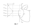
- FIG. 7 illustrates exemplary electrocardiogram signal electrical energy distribution at different locations in the central venous system.
- FIG. 8 depicts a graphical user interface according to an embodiment of the present invention.
- FIG. 9 depicts a graphical user interface according to another embodiment of the present invention.
- FIGS. 10A and 10B depict exemplary printouts for the information displayed by the graphical user interface, according to an embodiment of the present invention.
- FIG. 11 is a block diagram for a computer-based method for positioning an endovascular device in or near the heart using electrocardiogram signals.
- FIG. 12 illustrates another decision support algorithm for a computer-based method for positioning an endovascular device in or near the heart using electrocardiogram signals, according to one embodiment.
- FIG. 13 illustrates the cardiac conduction system of the heart.
- FIG. 14 illustrates electrical signal propagation in the conduction system of the heart.
- FIG. 15 illustrates electrical activity in the cardiovascular system due to neuronal control system.
- FIG. 16 illustrates a framework for analyzing the endovascular electrography signals, according to an embodiment of the present invention.
- FIG. 17 illustrates several embodiments for electrogram waveform processing.
- FIG. 18A shows ECG leads arranged to form an Einthoven triangle.
- FIGS. 18B-18F show various views of a skin ECG waveform and an endovascular ECG waveform as depicted on a graphical user interface according to one embodiment.
- FIGS. 19A and 19B show various views of a skin ECG waveform and an endovascular ECG waveform as depicted on a graphical user interface according to one embodiment.
- FIGS. 20A and 20F show various views of a skin ECG waveform and an endovascular ECG waveform as depicted on a graphical user interface according to one embodiment.
- FIGS. 21A and 21B show various views of a skin ECG waveform and an endovascular ECG waveform as depicted on a graphical user interface according to one embodiment.
- FIGS. 22A-22D show various magnetic sterile connectors according to certain embodiments.
- FIGS. 23A and 23B show various steerable sterile connectors according to certain embodiments.
- FIGS. 24A-24F show various views of a skin ECG waveform and an endovascular ECG waveform together with a heart icon to indicate a position of an endovascular device as depicted on a graphical user interface according to one embodiment.
- FIGS. 25A and 25B show various possible depictions for use in ECG signal-based guidance as displayed on a mobile phone according to one embodiment.
- FIG. 26 shows a depiction of the zooming of multiple ECG waveforms as displayed on a mobile phone according to one embodiment.
- FIGS. 27A and 27B show additional ECG waveform-related depictions as displayed on a mobile phone according to one embodiment.
- FIG. 28 is a view of skin and endovascular ECG waveforms together with additional elements as depicted on a graphical user interface according to one embodiment.
- FIG. 29 is a view of skin and endovascular ECG waveforms together with additional elements as depicted on a graphical user interface according to one embodiment.
- FIG. 30 is a view of skin and endovascular ECG waveforms together with additional elements as depicted on a graphical user interface according to one embodiment.
- FIG. 31 is a view of skin and endovascular ECG waveforms together with additional elements as depicted on a graphical user interface according to one embodiment.
- FIG. 32 is a view of skin and endovascular ECG waveforms together with additional elements as depicted on a graphical user interface according to one embodiment.
- FIG. 33 is a view of skin and endovascular ECG waveforms together with additional elements as depicted on a graphical user interface according to one embodiment.
- FIG. 34 is a view of skin and endovascular ECG waveforms together with additional elements as depicted on a graphical user interface according to one embodiment.
- FIG. 35 is a view of skin and endovascular ECG waveforms together with additional elements as depicted on a graphical user interface according to one embodiment.
- FIG. 36 is a table showing various ECG waveform energy values and ratios according to one embodiment.
- FIG. 37 is a graph showing energy vs. location for an endovascular ECG electrode and a skin ECG electrode.
- FIG. 38 is a simplified view of a heart and proximate vasculature showing various possible locations for positioning a catheter or other medical device.
- FIG. 39 is a view of a Doppler ultrasound signal, including various peaks and a region of interest, according to one embodiment.
- proximal refers to a direction relatively closer to a clinician using the device to be described herein
- distal refers to a direction relatively further from the clinician.
- end of a catheter placed within the body of a patient is considered a distal end of the catheter, while the catheter end remaining outside the body is a proximal end of the catheter.
- the words “including,” “has,” and “having,” as used herein, including the claims, shall have the same meaning as the word “comprising.”
- Embodiments of the present invention advantageously provide an inventive apparatus(es), computer-based data processing algorithms and methods for obtaining and using endovascular ECGs in a number of clinical applications and settings.
- inventive apparatus e.g., guiding central venous access devices in the superior vena cava, right atrium, and right ventricle.
- central venous access devices may include central venous catheters (CVC), peripherally inserted central catheters (PICC), implantable ports, hemodialysis catheters, tunneled catheters and others.
- CVC central venous catheters
- PICC peripherally inserted central catheters
- Other devices which may benefit from guidance with the inventive apparatus are temporary pacemaker leads placed through the central venous system.
- Catheters and guidewires used in left heart procedures may also benefit from the embodiments described herein by decreasing the amount of contrast and radiation required to guide these devices in position.
- the apparatus can be used for minimally invasive monitoring and assessing heart conditions based on its electrical activity, e.g., assessing preload in a heart cycle or monitoring ST segments and T-waves in congestive heart failure.
- an apparatus consisting of sterile adaptors, an electronic module for signal acquisition, a computer module, software, and peripheral devices and connections.
- the electronic module for signal acquisition can be dedicated to acquiring and processing endovascular electrical signals generated by the body (endovascular ECG), in another embodiment the electronic module can be dedicated to acquiring and processing endovascular ECGs as well as skin ECGs.
- the electronic module and the computer module can be separate modules, in another embodiment they can be integrated in the same module and enclosure, and yet in another embodiment they can communicate with each other via a wireless connection, such as Bluetooth.
- the apparatus can contain an integrated printer, while in another embodiment the printer can be external and attached to the apparatus and the apparatus connected via network, e.g., wireless to other devices.
- the apparatus can be used for telemetry and for transmitting the endovascular electrograms to a remote location, e.g., via a telephone line, Internet, and/or wireless phone. Any combination of embodiments mentioned above is also possible.
- the device consists of a connecting wire with two ends and special connectors at each end. At one end, the wire can be connected to a metal or nitinol guidewire or stylet as commonly available on the market. At the other end, the wire can be safely connected to the electronic module.
- the device includes a coated guidewire, e.g., made of nitinol or stainless steel with uncoated distal and proximal ends and cm markings. In such an embodiment, the coated guidewire is inserted endovascularly, while the connecting wire is connected to the proximal end of the coated guidewire.
- the device in another embodiment, includes a catheter-syringe adaptor provided with an electrical connecting wire.
- the electrical connecting wire is in contact with the fluid, e.g., saline flowing within the catheter-syringe adapter.
- the connecting wire can be connected to the electronic module.
- various electrode configurations allow for the optimal acquisition of endovascular ECGs.
- a single lead is used to provide information about the tip location of an endovascular device within the vasculature.
- a modified three lead configuration is used to provide simultaneous 3-lead monitoring of the heart activity at the same time with providing tip location information.
- a modified single lead configuration plus ground is used for telemetry and transferring information from the tip of the catheter remotely.
- algorithms are introduced for the analysis of the ECG waveforms and for supporting decision making based on these waveforms. These algorithms discriminate between different locations in the vasculature and assess body functions (systemic and at specific locations in the body), in particular heart functionality. In various embodiments, these algorithms use time domain analysis of waveforms: morphologic, for example shape; statistic, for example behavior.
- the algorithms use frequency domain analysis of waveforms: morphologic, for example shape; statistic, for example behavior.
- signal energy analysis in time and frequency domains is also performed, morphologic and statistic. Fuzzy, statistical, and knowledge-based decision making are also contemplated by the present embodiments as decision support tools.
- a user interface is provided that advantageously simplifies interpretation of data and workflow.
- the user interface includes simplified graphics showing the location in the vasculature and in the heart of the tip of the endovascular device in use without showing any of the ECG waveforms.
- the user interface shows, in real-time, the change in location of the tip of the endovascular device in use.
- a computer-based method that guides central venous catheters (CVC, PICCs, hemodialysis, implantable ports, and others) using stylets, guidewires and saline solution to the superior vena cava, inferior vena cava, the right atrium, and the right ventricle.
- CVC central venous catheters
- PICCs central venous catheters
- hemodialysis implantable ports
- saline solution to the superior vena cava, inferior vena cava, the right atrium, and the right ventricle.
- This method is advantageously less sensitive to patients with arrhythmias than the prior art, and represents an alternative to chest X-ray confirmation of tip location of central venous catheters in most clinical cases.
- a computer-based method is provided that guides coated guidewires in the right and left heart.
- a computer-based method that guides the placement of temporary pacemaker leads through the central venous system.
- a method is provided that is minimally invasive and monitors preload using depolarization and heart rhythms.
- a method is provided that is minimally invasive and monitors arrhythmias using P-wave analysis.
- a method is provided that is minimally invasive and monitors heart failure using ST segment and T-wave analysis.
- one or several skin electrodes are used to obtain skin surface ECG signals simultaneous with the acquisition of endovascular (intracavitary) electrogram (ECG) signals via the use of endovascular (intracavitary) electrodes.
- ECG electrogram
- the simultaneous and synchronized skin surface and endovascular ECG signals are used in one of several ways to analyze and quantify the ECG signals as a function of the location of the endovascular electrode, e.g. as a function of the tip of a catheter.
- the ease-of-use of the ECG-based catheter navigation and tip location is enhanced.
- skin ECG reference waveforms are simultaneously presented on a display with endovascular ECG waveforms measured at the tip of a catheter or other indwelling medical device.
- Such simultaneous acquisition and display of concurrent ECG signals allows for ready interpretation of the endovascular ECG waveform at the tip of the catheter.
- a skin ECG reference signal is used to synchronize information processing algorithms applied to the endovascular ECG signal, yielding results of enhanced reliability concerning changes of P-wave of the endovascular ECG signal in terms of shape and energy.
- analysis of the synchronized skin and/or endovascular ECG signals can be linked to one another and/or to the periodic electrical activity of the heart.
- a skin ECG lead can be used to detect the R-peak of the QRS complex of a detected skin ECG waveform. Detection of the R-peak in the skin ECG waveform can be used to trigger analysis of the endovascular ECG signal in a simultaneously corresponding segments of the endovascular ECG waveform, e.g., in the segment corresponding to the P-wave.
- Such triggering is particularly useful in case of arrhythmia, wherein the skin ECG waveform does not typically demonstrate a consistent P-wave, while the endovascular ECG waveform indeed includes a detectable P-wave segment that changes as a function of the location in the vasculature.
- magnetic and steerable sterile connectors are disclosed, as well as aspects of display and control solutions to enable a mobile phone or other handheld device to control an ECG-based system including one or more of the above aspects.
- a method for locating an indwelling medical device within a vasculature of a patient. The method comprises identifying an endovascular ECG waveform complex from an endovascular ECG signal associated with the indwelling medical device, then calculating an absolute value of the energy of the endovascular ECG waveform complex over a predetermined segment thereof. A position of the medical device within the vasculature is then determined by observation of the absolute value of the energy of the predetermined segment of the endovascular ECG waveform complex.
- FIG. 1A is a block diagram that depicts an apparatus according to an embodiment of the present invention.
- the apparatus 100 can be attached through an adaptor ( 120 ) to a large variety of commercially available and custom designed vascular access devices ( 110 ).
- vascular access devices examples include: central venous catheters (CVC), peripherally inserted central catheters (PICC), implantable ports, tunneled catheters, hemodialysis catheters, guiding catheters for pacemaker leads, guidewires used for coronary and other vascular interventions, guiding catheters for coronary and other vascular interventions, stylets, syringe needles, and others.
- CVC central venous catheters
- PICC peripherally inserted central catheters
- implantable ports implantable ports
- tunneled catheters hemodialysis catheters
- guiding catheters for pacemaker leads guidewires used for coronary and other vascular interventions
- guiding catheters for coronary and other vascular interventions stylets, syringe needles, and others.
- the vascular access devices is a stylet, a guidewire, or a syringe needle, its
- the hook or the alligator clip adaptor according to one embodiment should be used If the vascular access device is a catheter, than saline should be used to establish a conductive path through one of the catheter's lumens. In such a case, the syringe-catheter adaptor according to one embodiment should be used.
- the electronic module ( 130 ) receives electrical signals from the adaptor and from one or more other electrodes placed on the patient's skin ( 115 ). Alternatively, more than one adaptor can be used at the same time to connect to more than one endovascular device in order to provide different electrical signals to the electronic module. The use of skin electrodes is optional in certain device configurations.
- the electronic module processes the electrical signals and transmits them to a computer module ( 140 ) for further processing and other functions.
- the electronic module and the computer module can be packaged separately, and in another embodiment they can be integrated in the same package.
- the connection between the electronic module and the computer module can be hardwired ( 131 ), and in another embodiment the connection it can be wireless ( 132 ), e.g., using Bluetooth.
- the computer module ( 140 ) can be a notebook or a netbook, and in another embodiment the computer module can be a PDA or a mobile phone, e.g., an iPhone or an iPad.
- the computer module processes the signals from the electronic module applying algorithms ( 170 ) as described by current embodiments.
- the computer module can also be connected to peripherals ( 160 ), e.g., a printer or a label printer and storage devices and provides connectivity including wireless connectivity ( 150 ) to other computers or to the internet.
- peripherals ( 160 ) e.g., a printer or a label printer and storage devices and provides connectivity including wireless connectivity ( 150 ) to other computers or to the internet.
- the storage device can be used to store a database of knowledge and information regarding the application at hand.
- the connectivity interface can be used to update this database remotely with newest relevant knowledge and information, e.g., new clinical cases, new findings regarding the relationship between electrograms and heart conditions.
- the computer module supports a graphical user interface ( 180 ) optimized for the purpose of the clinical application at hand.
- FIG. 1B is a block diagram of an electronic module ( 2 ) for acquisition and processing of endovascular electrocardiogram according to an embodiment of the present invention.
- the patient connector interface ( 10 ) allows for connecting electrical leads to the patient ( 5 ). Any combination of skin electrodes and/or electrical connections to endovascular devices using the adaptors discussed above can be used.
- the amplifier ( 20 ) is a four stage amplifier with variable gain, which can amplify electrical signals coming through the patient cable, for example, typical of electrocardiographic values.
- the analog-to-digital converter ( 30 ) converts the signals in digital format readable by the micro-processor ( 40 ). Any number and configurations of microprocessors, microcontrollers, and digital signal processors can be used to implement the micro-processing function ( 45 ).
- a microcontroller is responsible for controlling the serial communication with a computer module ( 90 ) via the serial interface ( 70 ) or via the wireless interface ( 80 ) and a digital signal processor (DSP) is responsible for implementing one or several of the inventive algorithms described herein.
- DSP digital signal processor
- a single processor ( 46 ) can be used for both communication and processing.
- the micro-processor ( 40 ) also receives commands from the computer module ( 90 ) and controls different elements of the electronic module, e.g., the amplifier ( 20 ) accordingly.
- the patient isolation block ( 50 ) decouples electrically the power ( 60 ) and the serial communication channel ( 70 ) from the patient interface ( 10 ) in order to ensure patient protection to electrical shock.
- the isolation block ( 50 ) can consists of a transformer and/or couplers, e.g. optical couplers.
- FIG. 2 depicts an adaptor ( 200 ) for an endovascular device according to an embodiment of the present invention.
- Vascular access devices like catheters, syringes, syringe needles, stopcocks, infusion pumps and others connect to each other through standard connections.
- FIG. 2 such a standard connection between two devices is illustrated on device ( 201 ) by the luer ( 202 ) with inner diameter ( 203 ) and outer diameter ( 204 ), and on device ( 250 ) by threaded port ( 251 ) with inner diameter ( 252 ) and fluid opening diameter ( 253 ).
- the threaded port ( 251 ) and the luer ( 202 ) allow for connecting the two devices ( 201 , 250 ) by threading, attaching, coupling, etc., the port ( 251 ) into the luer ( 202 ).
- the adaptor ( 200 ) has a body ( 220 ) with two ends ( 226 , 227 ) with a length ( 225 ), and is made, for example, of strong biocompatible plastic material with some degree of elasticity.
- End ( 227 ) has a shape of a cone.
- end ( 227 ) has an elastic sealing portion ( 228 ) such that end ( 227 ) can easily fit in the luer ( 202 ) of device ( 201 ) to seal the connection for fluid flow.
- the other end ( 226 ) is in the shape of a standard luer with diameter ( 224 ), such as, for example, luer ( 202 ) of device ( 201 ).
- the threaded port ( 251 ) of the device ( 250 ) can be connected to end ( 226 ) of the adaptor ( 200 ).
- the cone piece ( 270 ) also allows a connection to a device that does not have a luer.
- the stand alone cone piece ( 270 ) allows a connection between two devices with different accessible diameters.
- the end ( 227 ) of adaptor ( 200 ) has a diameter ( 223 ) and fits inside the diameter ( 272 ) of the cone piece ( 270 ).
- the end ( 271 ) of the cone piece ( 270 ) fits in a simple catheter end portion ( 261 ) with a diameter ( 262 ) of a typical device ( 260 ).
- device ( 260 ) can be a catheter for an implantable port.
- device ( 201 ) is a syringe needle
- device ( 250 ) is a syringe.
- Fluid e.g., a conductive electrolyte
- a conductive metal ring ( 240 ) is attached to a portion of the substantially cylindrical surface of lumen ( 222 ) and, preferably, induces very little perturbations to the fluid flow.
- the metal ring ( 240 ) may be disposed within a recessed portion of the substantially cylindrical surface of the lumen ( 222 ).
- One end ( 230 ) of a conductive wire ( 233 ) is electrically coupled to the metal ring ( 240 ); in one embodiment, the end ( 230 ) is soldered to metal ring ( 240 ). In another embodiment, the end ( 230 ) is captured between the surface of the lumen ( 222 ) and the metal ring ( 240 ), and the end ( 230 ) and the metal ring ( 240 ) maintain good electrical contact through mechanical pressure.
- the wire ( 233 ) may be bare or insulated.
- the metal ring ( 240 ) is fixedly attached to the surface of lumen ( 222 ) using, for example, adhesive, an interference fit, a press fit, etc., while in other embodiments, the metal ring ( 240 ) may be removably attached to the surface of lumen ( 222 ), free-floating, etc.
- the wire ( 233 ) passes through a channel ( 231 ), which extends from the lumen ( 222 ) to an opening in the outer surface of the body ( 220 ).
- Epoxy ( 232 ), or other suitable material may be used to seal the opening of the channel ( 231 ), as well as to provide a strain relief for the wire ( 233 ).
- the metal ring ( 240 ) may be advantageously disposed adjacent to the channel ( 231 ) to provide additional sealing. Thus, the metal ring ( 240 ), the wire ( 233 ), the channel ( 231 ) and the epoxy ( 232 ) provide a sealed, electrical connection to the fluid flowing through the adaptor ( 200 ).
- a connector ( 234 ) may provide a standard electrical connection to the electrography system; a non-terminated wire may also be used.
- the wire ( 233 ) terminates at the opening of the channel ( 231 ) and the connector ( 234 ) is attached directly to the body ( 222 ), while in another embodiment, the wire ( 233 ) extends through the opening of the channel ( 231 ) and the connector ( 234 ) is attached to the free end of the wire ( 233 ).
- the substantially cylindrical surface of lumen ( 222 ) is tapered along the longitudinal direction ( 221 ). This taper may extend along the entire length of lumen ( 222 ), or restricted to a certain portion thereof.
- the surface of lumen ( 222 ) may be cone-shaped and have a larger diameter at the proximal end, or, alternatively, the larger diameter may be located at the distal end.
- device ( 201 ) is a syringe needle that is inserted into a lumen of a catheter for an implantable port
- device ( 250 ) is a syringe.
- the syringe is filled with saline, which is then injected into the catheter through the adaptor ( 200 ).
- the adaptor ( 200 ) becomes filled with saline solution, and, because the conductive metal ring ( 240 ) is in contact with saline and the conductive wire ( 233 ), an electrical connection is established between the catheter lumen and the wire ( 233 ). In this way, the electrical signal at the tip of the catheter may be measured through the saline solution.
- the adaptor ( 200 ) may be used with infusion pumps, as well as other types of power injections.
- the adaptor ( 200 ) does not include the metal ring ( 240 ), and the electrically conductive ending ( 230 ) is in direct contact with the electrolyte.
- FIG. 3 illustrates a catheter steering device according to an embodiment of the present invention.
- the catheter ( 300 ) is a triple lumen catheter and the distal end of each of the lumens is spaced with respect to each other.
- the catheter steering device can be used with any catheter having two or more lumens with spaced distal lumen openings.
- the open end of one lumen ( 306 ) of catheter ( 300 ) is at the very distal end of the catheter, another end or opening of a lumen ( 305 ) is spaced back from the distal end and the end or opening of the third lumen ( 307 ) is spaced back compared to the second end ( 305 ).
- the distance between the open end ( 306 ) and the end ( 307 ) is typically from one to several centimeters.
- the inventive steering device can accommodate such catheters.
- the typical length of a catheter is 50 to 60 centimeters and the spacing between the distal lumen ends ( 305 , 306 , and 307 ) is from one to several centimeters.
- a hemodialysis catheter with two lumens can typically be 20 to 40 centimeters in length, with one to several centimeters spacing between the distal ends of the two lumens.
- a multi-lumen central venous catheter (CVC) can typically be 15 to 25 cm in length with spacing between distal ends or openings of the lumens being from several millimeters to several centimeters.
- the catheter has a catheter hub ( 301 ) which splits the three lumens and connects each of them with a luer ( 302 , 303 , 304 ).
- the inventive catheter steering device includes a stylet ( 310 ) with a handle ( 311 ) at the proximal end to allow for pushing, pulling, and removal after use, and a steering member ( 320 ) which connects to the distal end of the stylet ( 322 ) and which can be fed back into a distal lumen opening of one of the other lumens, such as, for example, lumen ( 307 ).
- the steering member ( 320 ) returns to the proximal end of the catheter through the catheter lumen and exits at the proximal end through the luer corresponding to the respective lumen ( 304 ). So disposed, the steering device is in the installed position.
- the member ( 320 ) has a handle ( 321 ) which can be used to pull the member through the lumen.
- the handle ( 321 ) is detachable from the member ( 320 ).
- the member ( 320 ) may be polyurethane, silicone, PTFE, or other similar materials. In different embodiments, the member ( 320 ) may be any kind of biocompatible thread, e.g., surgical thread. In another embodiment, the member ( 320 ) is stainless steel wire.
- the stylet is provided pre-inserted into one of the catheter lumens, typically the central lumen with the most distal opening ( 306 ) with the member 320 attached at the distal end of the stylet ( 322 ) and pre-inserted into the lumen ( 304 ) through the lumen opening ( 307 ). In order to steer the catheter, the user pulls the member 320 out of the catheter while preventing the stylet 310 to be pulled into the catheter.
- the catheter tip can be bent in a desired direction. This situation is illustrated by the bent catheter tip ( 350 ), the member ( 340 ) which was pulled back and the member ( 330 ) which is its initial position with respect to the catheter.
- the stylet ( 310 ) or the steering member ( 320 ), or both are made of any electrically conductive material, then each or both of them can be used to measure electrical signals or endovascular electrograms at the distal tip of the catheter by connecting their proximal ends to the endovascular electrography system.
- the steering member ( 320 ) can be tied to the stylet ( 310 ) through the opening ( 307 ) of the catheter lumen.
- the stylet ( 310 ) and the steering member ( 320 ) are manufactured as a single component to form an extended steering member that is looped back through the opening ( 305 ) of a different catheter lumen.
- the stylet ( 310 ) can be inserted in one lumen and the steering member ( 320 ) can be inserted in the other lumen, such that the effect of bending the catheter tip can be achieved by pulling the proximal ends.
- the steering member ( 320 ) can be inserted in the lumen ( 302 ) and through the opening ( 305 ).
- FIGS. 4A, 4B, 4C, and 4D depict electrode configurations that provide optimal acquisition of endovascular electrocardiogram according to various embodiments of the present invention.
- FIG. 4A depicts a single lead configuration with a reference electrode ( 410 ), for example attached to the patient's skin over the right arm and with the other electrode attached through an adaptor to an endovascular device ( 415 ).
- the reference electrode attached to the skin over the right arm is presented in this configuration for illustration purposes only. Other locations of the reference electrode are possible depending on the type of ECG required.
- the reference electrode over the right arm together with the tip of the endovascular device used with the adaptor can be similar to lead II of a standard ECG. In this case the ECGs obtained from the superior vena cava ( 401 ) and inferior vena cava ( 402 ) can be optimized.
- the reference electrode can be attached to the skin in any other location in order to simulate other leads of the standard ECG.
- the reference electrode can be also connected to adaptors attached to other endovascular devices in order to obtain more local information from within the patient's heart ( 400 ).
- FIG. 4B depicts a modified 3-lead configuration, with monitoring and guiding capabilities, with 4 electrodes.
- Three (3) electrodes correspond to the standard ECG electrodes: right arm (RA, 420 ), left arm (LA, 425 ), and left leg (LL, 430 ) used as reference.
- the fourth electrode is attached through an adapter to the endovascular device (C, 435 ).
- the electronic module and the algorithm perform two functions simultaneously: the three standard electrodes (RA, LL, and LL) perform a monitoring function of the heart, while the C electrode ( 435 ) allow for recording the ECG at the tip of device.
- FIG. 4C depicts a telemetry configuration with a single grounded lead, including the configuration illustrated in FIG. 4A and a ground reference ( 450 ). This configuration can be used to transmit ECGs remotely through a telemetry system configuration.
- FIG. 4D depicts one use of ECG monitors for guiding endovascular devices.
- a standard ECG monitor is used having standard inputs RA ( 465 ), LA ( 460 ), and LL ( 470 ).
- LA ( 460 ) is connected to the left arm and LL ( 470 ) to the left leg of the patient.
- the RA input ( 465 ) is connected to a switch which can be used be the clinician to switch the RA input ( 465 ) between the RA electrode and the catheter (C) electrode 475 .
- a switch which can be used be the clinician to switch the RA input ( 465 ) between the RA electrode and the catheter (C) electrode 475 .
- FIG. 5 illustrates exemplary electrocardiogram signal amplitudes at different locations in the central venous system.
- the heart ( 504 ), right atrium ( 501 ), superior vena cava (SVC) ( 502 ), and the inferior vena cava (IVC) ( 503 ) are illustrated.
- Location A is in the upper SVC
- location B is in the lower third of the SVC
- location C is at the caval-atrial junction
- location D is in the right atrium
- location E is in the upper inferior vena cava.
- Graph 510 illustrates an ECG waveform as a function of time at recorded at location A.
- the absolute amplitude of the waveforms is recorded on an amplitude scale ( 590 ).
- the standard elements of the electrocardiogram are illustrated: the P-wave ( 560 ), the R-wave ( 570 ), and the T-wave ( 580 ).
- the amplitudes and shape at location A recorded with a lead configuration as in FIG. 4D are similar to an electrocardiogram recoded at the skin level with the same electrode configuration.
- Graph 520 illustrates an endovascular ECG depicted at location B.
- the amplitude at this location is higher than the one at location A but the overall shapes of the waveform are similar at location A and B.
- Graph 530 illustrates an endovascular ECG depicted at location C.
- the amplitude of the waveform is yet higher than the one at location B and the P-wave has dramatically changed becoming higher than the R-wave.
- This waveform is an indication of the proximity of the sino-atrial node.
- Graph 540 illustrates an endovascular ECG depicted at location D. At location D in the right atrium, the amplitudes are similar to location C but the P-wave changes polarity becoming bi-polar. This is an indication that the measurement of the ECG occurs beyond the sino-atrial node.
- Graph 550 illustrates an endovascular ECG depicted at location E.
- the waveform is similar to the one at location A in terms of amplitude except the P-wave has reverse polarity.
- the differences in the ECG waveforms at different locations are used by the algorithms introduced herein to discriminate between the corresponding locations and to assess heart and blood vessel functionality.
- FIG. 6 illustrates exemplary electrocardiogram signal power spectra at different locations in the central venous system, using a spectral scale ( 690 ).
- Graph 610 illustrates an endovascular ECG spectrum depicted at location A.
- the spectrum ( 610 ) has the appearance of a single central frequency or single band ( 660 ) and with a frequency distribution spectral power and energy similar to those at skin level.
- Graph 620 illustrates an endovascular ECG spectrum depicted at location B.
- the frequency distribution has two major bands and a higher energy and spectral power than the one at location A.
- Graph 630 illustrates an endovascular ECG spectrum at location C.
- location C there are multiple (3-4) major frequencies or principal spectral components distributed over a wider range of frequencies ( 670 ). This spectral distribution is indicative of the energy distribution around the sino-atrial node. The spectral power and signal energy have increased compared to location B.
- Graph 640 illustrates an endovascular ECG spectrum depicted at location D. At location D the spectrum is wider and more broadband indicative of the electrical activity of the right atrium.
- Graph 650 illustrates an endovascular ECG spectrum depicted at location E.
- the frequency spectrum at location E is similar to the one at location A.
- the differences in the spectral waveforms at different locations are used by the algorithms introduced herein to discriminate between the corresponding locations and to assess heart and blood vessel functionality.
- FIG. 7 illustrates exemplary electrocardiogram signal electrical energy distribution at different locations in the central venous system.
- the heart ( 704 ), right atrium ( 701 ), superior vena cava (SVC) ( 702 ), and the inferior vena cava (IVC) ( 703 ) are illustrated.
- FIG. 16 a framework for analyzing the endovascular electrography signals according to an embodiment of the present invention is illustrated.
- the heart is represented by ( 1600 ), the superior vena cava by ( 1601 ), the inferior vena cava by ( 1602 ) and the right atrium by ( 1603 ).
- the graph ( 1620 ) illustrates the electrical energy profile as a function of location in the heart and the graph ( 1640 ) illustrates the different electrography waveforms which can be obtained at different locations in the heart.
- the curve ( 1630 ) illustrates the increase of electrical energy detected in each of the regions at the tip of an endovascular catheter advancing from the superior vena cava into the heart.
- the energy curve is calculated in time domain, while in another embodiment, the energy curve is calculated in the frequency domain using the frequency spectrum.
- the energy is calculated for the actual signal levels, while in another embodiment, the baseline value or other mean values are first subtracted from the signal values before energy calculations.
- the signal energy or power is calculated in time domain by summing up the squared amplitude values before and/or after baseline subtraction over a determined period of time, e.g., a heartbeat.
- the signal energy or power is calculated by summing up the squared values of the frequency components.
- the curve is calculated using the entire electrogram, while in other embodiments, only certain segments of the electrogram are used for the energy calculations, e.g., only the segment corresponding to a “P-wave” of an electrocardiogram. Such a “P-wave” segment is representative of the electrical activity of the sino-atrial node.
- Threshold ( 1631 ) of energy level defines the beginning of the lower third of the superior vena cava.
- the energy levels ( 1621 ) define the regions in the vasculature of low energy which are distant or further away from the sino-atrial node.
- the energy levels ( 1622 ) between thresholds ( 1631 ) and ( 1632 ) define the region labeled as the lower third of the superior vena cava ( 1625 and 1605 ).
- the energy levels ( 1623 ) between thresholds ( 1632 ) and ( 1633 ) define the region labeled as the caval-atrial junction ( 1626 and 1606 ).
- the energy levels ( 1624 ) between thresholds ( 1633 ) and ( 1634 ) define the region labeled right atrium ( 1627 and 1607 ).
- the shape and size of the electrogram in graph ( 1640 ) relative to a baseline ( 1650 ) can be correlated to a location in the heart.
- Thresholds ( 1631 ), ( 1632 ), ( 1633 ), and ( 1634 ) are determined specifically for the type of energy considered for calculations, e.g. the entire electrogram, the P-wave, and/or the S-T segment.
- the P-wave ( 1651 ) and the R-wave ( 1652 ) are similar in size and shape with a standard electrocardiogram lead II recorded at the skin level if the right arm standard ECG lead is connected to the catheter and measuring the electrogram signal at the tip of the catheter.
- the energy level of the electrogram increases, the electrogram amplitudes increase and the P-wave ( 1653 ) increases amplitude and energy relative to the R-wave ( 1654 ) to where the P-wave amplitude and energy between half and three quarters of the amplitude and energy of the R-wave.
- the energy level of the electrogram increases further, the electrogram amplitudes continue to increase and the P-wave ( 1655 ) increases amplitude and energy relative to the R-wave ( 1656 ) to where the P-wave amplitude and energy are larger or equal to the amplitude and energy of the R-wave.
- the energy level of the electrogram increases further, the electrogram amplitudes increase, the P-wave ( 1657 ) becomes bipolar and its amplitude and energy relative to the R-wave ( 1658 ) start decreasing.
- These behaviors are quantified, analyzed, and used in order to provide location information regarding the tip of the catheter.
- Graphs ( 1710 ) and ( 1720 ) illustrate a P-wave analysis embodiment. Since the P-wave corresponds to electrical activity of the heart generated by the sino-atrial node, the changes of the P-wave are most relevant with respect to determining the proximity of the sino-atrial node in an endovascular approach. Therefore, in order to assess proximity of the sino-atrial node and location in the vasculature, signal analysis methods in time and frequency domains, as well as signal energy criteria can be applied only to the P-wave segment of an electrogram.
- the segment designated for the P-wave analysis ( 1711 ) starts at moment ( 1713 ) and ends at moment ( 1714 ).
- the highest amplitude detected corresponds to the P-wave peak ( 1712 ).
- the starting moment ( 1713 ) of the P-wave segment analysis can be determined in a number of ways.
- the heart beat is calculated and the R-peak is detected as the maximum amplitude of the heart beat. Going back from each R-peak a certain percentage of the heart beat, for example between 20% and 30%, determines the moment when the analysis of the P-wave starts ( 1713 ).
- the designated segment for the P-wave analysis ( 1721 ) starts at moment ( 1723 ) in the heart cycle and ends at moment ( 1724 ).
- the P-wave in this case is bipolar with a positive maximum amplitude ( 1722 ) and a negative maximum amplitude ( 1725 ) when compared to the baseline (amplitude equals zero).
- time-domain and frequency-domain algorithms are applied according to embodiments of the present invention.
- Graph ( 1730 ) illustrates the advantages of baseline subtraction prior to signal energy computation. If the signal energy is calculated in time domain as the sum of the squared signal amplitudes over a heartbeat, then the amplitude variations between levels ( 1731 and 1732 ) around baseline ( 1733 ) may lead to a lower energy level than the signal with amplitude variations between levels ( 1734 and 1735 ) whereby the level ( 1734 ) is the baseline. The baseline value ( 1733 ) is subtracted from the amplitude values ( 1731 to 1732 ) and the baseline value ( 1734 ) is subtracted from the amplitude values ( 1734 to 1735 ). After subtracting the baseline, the sum of squared amplitude values is calculated. Thus, this sum is proportional to the energy of signal variation around the baseline and therefore it is more appropriate to characterize changes in the signal values/behavior.
- Graph ( 1740 ) shows a typical electrogram waveform with a P-wave ( 1741 ) and an R-wave ( 1742 ) and a distorted signal with the P-wave covered by high frequency noise ( 1744 ) and the R-wave saturated to a maximum value ( 1743 ).
- an algorithm is used to detect the presence of artifacts and reduce the amount of artifacts as much as possible. If, after reducing the artifacts, the signal cannot be recovered, then the signal is discarded for the computation of signal energy.
- the presence of artifacts can be detected in time domain by a high value of the derivative and of its integral, a jump in signal energy, a jump in the value of the baseline or in different averages calculated from the signal.
- the artifacts can be detected as a jump in the value of the DC component (frequency zero of the spectrum), as the sudden appearance of high frequency components, and in a jump of the spectral power/energy.
- selective filtering can be applied and all components removed, which are not “typical” for the average behavior of the signal. After selective filtering, the signal is reconstructed in the time domain using an inverse Fourier transform in order to allow for verification of the success of the selective filtering.
- FIG. 8 depicts a graphical user interface according to an embodiment of the present invention.
- Window ( 810 ) presents the ECG waveform in real-time as it is acquired by the electronic module using the attached electrode configuration.
- Window ( 820 ) is a reference window and shows a frozen waveform used to compare with the current window.
- the reference waveform in window ( 820 ) can be obtained through the electrodes connected to the electronic module at a reference location of the catheter and/or using a reference configuration of the skin electrodes.
- such a reference waveform can be the ECG recorded using an adaptor according to an embodiment of the present invention connected to an endovascular device placed at the caval-atrial junction.
- the reference waveform in window 820 can be a typical waveform at a certain location in the vasculature or of a certain heart condition as it is recorded in a database of waveforms and as it is stored in the storage medium of the computer system. If the electrode configuration allows for simultaneous heart monitoring and recording of electrograms using an endovascular device, window ( 830 ) shows one of the standard ECG leads for heart monitoring, while window ( 810 ) shows the ECG at the tip of the endovascular devices when connected to an adaptor, such as the ones discussed above.
- the icon ( 870 ) is a representation of the heart, and the locations A through E ( 875 ) illustrate different locations in the heart and vascular system which can be discriminated by analyzing endovascular ECGs in accordance with the methods disclosed herein. As a location in the vasculature is identified by the algorithms, the corresponding place and letter on the icon ( 875 ) becomes highlighted or in some other way is made visible to the user.
- the bars ( 884 ), ( 885 ), and ( 886 ) show signal energy levels.
- the “E” bar ( 885 ) presents the amount of electrical energy computed from the ECG frequency spectrum at the current location of the tip of the endovascular device.
- the “R” bar ( 884 ) presents the amount of electrical energy computed from the ECG frequency spectrum at a reference location.
- the “M” bar ( 886 ) presents amount of electrical energy computed from the ECG frequency spectrum using the monitoring ECG signal from the skin electrodes.
- the window ( 840 ) depicts monitoring information, e.g., heart rate. Patient information (name, date of procedure and others) are shown in window ( 850 ).
- Window ( 860 ) contains system control elements like buttons and status information, e.g., scale, scroll speed, system parameters and system diagnostics.
- FIG. 9 depicts a graphical user interface according to another embodiment of the present invention.
- the icon ( 920 ) is a representation of the heart and the locations A through E ( 930 ) illustrate different locations in the heart and vascular system which can be discriminated by analyzing endovascular ECGs. As a location in the vasculature is identified by the algorithms, the corresponding place and letter on the icon ( 930 ) becomes highlighted or in some other way is made visible to the user.
- the bars ( 940 ), ( 950 ), and ( 960 ) show signal energy levels.
- the “E” bar ( 940 ) depicts the amount of electrical energy computed from the ECG frequency spectrum at the current location of the tip of the endovascular device.
- the “R” bar ( 950 ) shows the amount of electrical energy computed from the ECG frequency spectrum at a reference location.
- the “M” bar ( 960 ) shows amount of electrical energy computed from the ECG frequency spectrum using the monitoring ECG signal coming from the skin electrodes.
- the button “Print” ( 960 ) allows the user to print the information documenting the case on a printer, for example on a label printer for quick attachment to the patient's chart.
- FIGS. 10A and 10B depict exemplary printouts for the information displayed by the graphical user interface, according to an embodiment of the present invention.
- FIG. 10A illustrates a printout ( 1000 ) for the case of a catheter tip placement procedure in the lower third of the SVC.
- the field 1010 depicts the heart icon whereby the letter “B” corresponding to the lower third of the superior vena cava (SVC) is highlighted ( 1040 ).
- Field 1030 depicts the reference ECG waveform recorded at the tip of the catheter at the caval-atrial junction in the proximity of the sino-atrial node.
- Field 1020 depicts the ECG waveform at the tip of the catheter in the position in which it was placed at the end of the procedure. For FIG. 10A , this location is in the lower third of the SVC and the ECG waveform corresponds to this location.
- the patient name ( 1001 ) and the date of procedure ( 1002 ) are also printed.
- FIG. 10B depicts a similar printout ( 1050 ) except that the final position at the end of the procedure is at the caval-atrial junction at location C ( 1090 ) on the heart icon ( 1060 ).
- the “SA Node” field depicts the reference ECG waveform ( 1080 ), and the “Final Position” field ( 1070 ) shows that the catheter was placed with the tip at the sino-atrial node: the ECG waveform in final location is similar or even identical with the one in the reference location at the sino-atrial node (SA Node). It is known that the proximity of the SA Node indicates a location at the caval-atrial junction. These locations are sometimes considered identical by some clinicians.
- FIG. 11 is a block diagram for a computer-based method ( 1100 ) for positioning an endovascular device in or near the heart using electrocardiogram signals.
- the algorithms are applied to the input signal ( 1102 ) (ECG) acquired by the adaptor to the endovascular devices and, optionally, through skin electrodes as well.
- ECG input signal
- the Error Detection Block ( 1105 ) detects at least three types of error conditions/exceptions, such as, for example, when a defibrillator has been applied to the patient, when a pacemaker is firing excitation pulses and/or when a lead/electrode is off. These errors/exceptions may be handled differently, and the user may be informed about the presence of an exception and the way of handling the exception ( 1110 ).
- the Pre-Processing block ( 1115 ) may amplify the signal, reduce noise, eliminate artifacts, etc. In one embodiment, rescaling the signal to the display range occurs under user control and is not automatic, as with most currently available ECG monitors. Thus, changes in the amplitude of the ECGs are easily noticed.
- a high-pass filter corrects the baseline and reduces such artifacts as respiratory artifact.
- Wideband noise suppression may be achieved using a selective filter, e.g., a wavelet transform. Electromagnetic interference with other equipment and the power grid may be suppressed by a notch filter (narrow band filter) centered at 60 Hz or 50 Hz to accommodate domestic or international power supplies.
- High frequency noise may be suppressed with a low-pass filter, which, in one embodiment, is implemented with variable length averaging, such as, for example, a running window corresponding to a heart cycle, an averaging of the ECG over several consecutive heart cycles, etc.
- the Adaptive Filtering block ( 1120 ) optimizes the filter coefficients by minimizing an error signal.
- the Time-Domain Pattern Recognition block ( 1130 ) identifies elements of the ECG waveform, their relationship(s) and their behavior(s) in time.
- the ECGs are analyzed in real time for certain elements, and, for other elements, a data buffer with an appropriate buffer length is maintained in the memory of the electronic and/or computer modules in order to allow for historic data analysis and prediction based on this analysis.
- the data history buffer is several seconds long allowing for the ECG signal corresponding to several heartbeats to be saved in the buffer.
- a double buffering technique allows the waveform in one buffer to be processed while the second buffer continues to store signals.
- elements of interest may include, but are not limited to, one or more of the following:
- the polarity of the P-wave single positive, single negative, or bipolarity
- additional computations include:
- Baseline subtraction for example for removing of respiratory artifacts and in order to allow for the analysis of changes with respect to the baseline;
- additional computations include:
- Selective filtering i.e., the removal of certain frequencies associated with artifacts and noise, e.g., high frequency noise, muscle artifacts, changes in signal due to catheter and electrode handling, etc.;
- ECG waveforms including, but not limited to, one or more of the following:
- the Fast Fourier Transform in block ( 1125 ) performs a Fast Fourier Transform on a number of ECG samples stored in a buffer of a certain length, e.g., 256, 512, 1024, 2048 or more data samples.
- the Fourier Transform transforms the waveform from the time domain into the frequency domain.
- the Frequency-Domain Pattern Recognition block ( 1140 ) illustrates various aspects of pattern recognition performed on the ECGs in the frequency domain, including, but not limited to, one or more of the following:
- block ( 1150 ) supports placing an endovascular device in either the lower third of the SVC or at the caval-atrial junction.
- block 1150 is based on the concept of first reaching the caval-atrial junction during catheter placement.
- the P-wave and other electrical parameters reach a maximum value.
- the P-wave is unipolar.
- the catheter is pulled back several centimeters until the P-wave decreases to half the amplitude reached at the caval-atrial junction.
- the catheter At the location where the P-wave has decreased to half the amplitude as the caval-atrial junction, the catheter is considered to be in the lower third of the superior vena cava.
- the signal is processed, over a plurality of predetermined time periods, to calculate a P-wave amplitude and a spectral power for each predetermined time period.
- a maximum P-wave amplitude is then determined from the plurality of P-wave amplitudes, as well as an associated maximum spectral power from the plurality of spectral powers.
- the location at which these maximum values are determined is associated with a predetermined location in or near the heart, such as the cava-atrial junction.
- the location of the endovascular device is then calculated, for each predetermined time period, based on a ratio of the P-wave amplitude to the maximum P-wave amplitude and a ratio of the spectral power to the maximum spectral power, and the location of the endovascular device is then displayed to the user. Additionally, the polarity of the P-wave and the R-wave amplitude may also be used to determine the location of the endovascular device.
- T 1 , T 2 , and T 3 may be empirically established thresholds which are different for each patient, and the algorithm can use an adaptive loop to adjust the thresholds based on the current measurements. In another embodiment, these thresholds are predetermined.
- the ratio between the P-peak/P amplitude or the P-wave peak-to-peak amplitude to the R-peak/R amplitude or to the QRS complex peak-to-peak amplitude can also be used to establish location relative to the sino-atrial node.
- the P-peak/amplitude must be approximately half of the R-peak/amplitude and the P-wave must be unipolar for the location to correspond to the lower third of the SVC.
- the P-wave peak-to-peak must be half of the QRS peak-to-peak amplitude and the P-wave must be unipolar for the location to correspond to the lower third of the SVC.
- results of the decision support algorithms block 1150 may be presented to the user, for example, by high lightening the appropriate location on the heart icon corresponding to the type of ECG identified by the system ( 1160 ).
- the decision support algorithm block 1250 is based on comparing the P-wave, R-wave and P-wave spectral power at the current locations with the values of these parameters determined from the skin electrocardiograms in an equivalent lead, e.g., lead II.
- Thresholds T 1 through T 6 are empirical values subject to adaptive adjustments relative to each patient. Each of the criteria or a combination of criteria shown in FIG. 12 can be used.
- one criterion may be that, at the location corresponding to the lower third of the SVC, the average electrical energy calculated from the endovascular ECG is twice as high as the average electrical energy calculated from the endovascular ECG at skin level or from a skin ECG in a corresponding lead, e.g., lead II.
- CVC central venous catheter
- CVC vascular access device
- step 11 If using saline and adaptor ( 200 ), go to step 11; if not, proceed as follows. Insert a guidewire into the CVC and flush align the guidewire tip and the catheter tip. Measure the length of the guidewire outside the CVC. This measurement is necessary in order to be able to realign the tip of the catheter and of the guidewire after inserting the guidewire in the vasculature. After taking the measurement, for example with sterile measuring tape or with surgical thread, remove the guidewire from the CVC.
- ECG waveform shown on the display of the electrography system indicates desired position of the catheter tip per the instructions for use of the electrography system: in the lower third of the SVC, at the caval atrial junction or in the right atrium.
- the location of the tip of the catheter will be identifiable through the specific shape of the P-wave and of the P-wave relative to the R-wave of the electrogram and/or by energy levels and thresholds.
- a method of placing the catheter piece of an implantable port is similar to the method for placing a CVC.
- the adaptor ( 200 ) should be connected to the catheter of the implantable port, and the syringe with saline must be connected to the other end of the universal adaptor.
- a different electrical adaptor should be connected to a syringe needle placed in the catheter of the implantable port. After reaching the desire position, the catheter should be connected to the implantable port.
- Both open-ended and closed-ended peripherally inserted central catheters can be placed as described herein, and the method of PICC placement is similar to the one of placing CVCs.
- the inventive steering mechanism described herein can be used to bend the tip of the PICC in case the catheter fails to advance in the desired direction.
- a method for placing hemodialysis catheters is similar to the method introduced herein for placing CVCs.
- the inventive steering mechanism described herein can be used to bend the tip of the hemodialysis catheter in case the catheter fails to advance in the desired direction.
- Two different guidewires with adaptors ( 220 ) can be used for each of the lumens of the hemodialysis catheter as to guide placement of one lumen into the right atrium and of the other lumen at the caval atrial junction using the electrography system.
- Each of the lumens of the hemodialysis catheter can be placed independently in sequence or at the same time by connecting the adaptors ( 220 ) of each of the lumens with different electrodes of the ECG cable of the electrograph system.
- the algorithm uses the energy as measured from the endovascular electrogram in order to map certain location in the vasculature. As such, this algorithm can be used to guide placement in patients with arrhythmias when only the electrical energy is indicative of location but not the shape of the P-wave.
- an electrical adaptor or adaptor ( 200 ) connected to the electrography system can be used for monitoring.
- the electrical adaptor can be connected to any stylet or other conductive member introduced in any venous access device or in any arterial device.
- Adapter ( 200 ) can also be connected to any venous or arterial line as long as the infusion of a conductive solution, e.g., saline is possible.
- Adapter ( 200 ) can also be used when electrically conductive fluids are inserted in the body using an infusion pump. Monitoring the tip location and/or certain aspects of the electrical activity of the heart can be performed in a number of clinical situations.
- Adaptor ( 200 ) can be attached to a number of central venous devices post insertion, e.g., at bedside and/or in home care situations: PICCs, CVC, hemodialysis catheters.
- Adaptor ( 200 ) can be connected to an arterial line between the arterial line and the other devices connected to the arterial line.
- the blood present in the arterial line and in the universal adaptor ensures the electrical connection between the blood and the electrography system.
- the electrical activity of the heart can be continuously monitored. This is particularly important in the case of monitoring the preload changes which translate in changes of the electrical energy of the heart during the S-T segment of the ECG waveform.
- Monitoring of the tip location and of the electrical activity of the heart can also be achieved by using the electrography system and connecting the adaptor ( 200 ) between a central venous line and a pressure measuring system while performing central venous pressure measurements.
- a needle can be inserted into the port chamber and the catheter can be flushed with saline using a syringe filled with saline.
- An electrical adaptor can be attached to the needle and to the electrography system.
- the detected electrogram signal will contain information from the skin level where the needle is in contact with the skin and from the tip of the catheter through the injected saline column. Since the impedance of the path to the catheter tip is lower than the one to the skin, the detected signal contains both components, i.e., at the skin level and at the tip of the catheter. By subtracting the skin level signal, the signal at the tip of the catheter can be estimated and thus the tip position and certain electrical activity of the heart according to the algorithms described in embodiments of the present invention.
- FIG. 13 illustrates the cardiac conduction system of the heart
- FIG. 14 illustrates electrical signal propagation in the conduction system of the heart.
- the conduction system of the heart begins with the heart's dominant pacemaker, the sino-atrial node ( 1310 ).
- the intrinsic rate of the SA node is 60 to 100 beats/minute.
- an impulse leaves the SA node, it travels through the atria along the Bachmann's bundle ( 1350 ) and the inter-nodal pathways, on its way to the atro-ventricular (AV) node ( 1320 ) and ventricles. After the impulse passes through the AV node, it travels to the ventricles, first down to the bundle of His ( 1330 ) then along the bundle branches and finally down to the Purkinje fibers ( 1340 ).
- Pacemaker cells in the junctional tissue and Purkinje fibers on the ventricles normally remain dormant because they receive impulses from the SA node. They initiate an impulse only they do not receive one from the SA node.
- the intrinsic rate of the AV junction is 40 to 60 beats/minute, the intrinsic rate of the ventricles 20 to 40 beats/minute.
- the different propagation speeds of the electrical impulses are shown in FIG. 14 . From the SA node ( 1410 ) the impulses propagate through the atrial muscle ( 1420 ) and through the ventricular muscle ( 1460 ) at app. 0.5 ms, through the bundle branches ( 1440 ) and ( 1450 ) at app. 2 m/sec, through the Purkinje fibers ( 1470 ) at app 4 m/s and through the AV node ( 1430 ) at app. 0.05 m/s.
- the electrical signals and the electrical energy distribution are advantageously used to identify the proximity of the sino-atrial node and right atrial electrical activity even in the cases of arrhythmia, i.e., in the absence of a coherent P-wave measured by standard skin electrocardiogram. While in some cases of arrhythmia random electrical signal generated in the right atrium is not coherent enough to propagate through the body to the skin, the electrical energy is still present in the right atrium and can be detected by local endovascular measurements as a non-coherent P-wave, i.e., as significant electrical activity in the P-segment of the ECG waveform. Energy measurements are also less sensitive to some local abnormalities in impulse conduction: altered automaticity (arrhythmias), retrograde conduction of impulses, reentry abnormalities.
- the electrical signals and the electrical energy distribution are also advantageously used to quantify heart functionality, e.g., preload which is related to the depolarization and extension of the heart muscle.
- the electrical signals and the electrical energy distribution are also advantageously used to guide guidewires and guiding catheters through the aorta into the left heart. This method is useful in simplifying the access to the left atrium and to the coronary arteries and in reducing the amount of contrast and radiation needed to guide endovascular devices to those locations.
- the inventive apparatus can also be used to guide catheters, e.g. Swan-Ganz through the right ventricle into the pulmonary artery.
- Other endovascular devices can be guided and be used to measure endovascular electrical activity in other locations of the cardiovascular system which are identifiable by the cardiograms measured with the new apparatus introduced in embodiments of the present invention.
- FIG. 15 illustrates electrical activity in the cardiovascular system due to neuronal control system.
- receptors 1510
- pressure receptors transmit information related to the state of the blood vessels and to the state of the heart to the nervous system through the Medullary centers ( 1500 ).
- the hypothalamus ( 1540 ) and the higher centers ( 1550 ) are involved in processing and reacting to the information received from the sensors/receptors. In turn they send impulses ( 1560 ) back to blood vessels and the heart.
- FIG. 18A illustrates the Einthoven ECG triangle and the naming convention for the ECG leads as they are used herein in connection with various embodiments.
- one electrode is placed on the right arm (RA), one on the left arm (LA) and one is used as reference on the left leg (LL).
- the direction in which the P-wave changes most is shown by the arrow ( 2200 ). Therefore, when using endovascular ECG for catheter navigation and tip location, the electrode corresponding to the right arm (RA) is operably connected to the proximal end of the vascular access device ( 110 ) ( FIG. 1A ), such as a catheter, in one embodiment.
- an ECG waveform detected with respect to the distal end of the catheter can be considered as detected by Lead II of the Einthoven triangle.
- Lead II will show most significant changes of the P-wave and therefore is best suited to detect the proximity of the sino-atrial node.
- the sino-atrial node is located at the caval-atrial junction and is responsible for generating the P-wave (indicative of the right-atrial electrical activity).
- the waveform corresponding to Lead III in the Einthoven triangle remains relatively unchanged as the catheter navigates through the vasculature in one embodiment if the RA electrode is operably connected to the catheter.
- Lead III is used in an embodiment of the present invention as a reference lead which serves multiple purposes, as described herein.
- the apparatus introduced herein displays simultaneously ECG signal-based waveforms for Lead II, also referred to herein as the endovascular ECG lead, (for catheter navigation and tip positioning) and for Lead III, also referred to herein as the skin ECG lead, (as a reference waveform).
- FIG. 5 illustrates the mapping of different endovascular ECG waveforms to the corresponding locations in the vasculature and in the heart, according to one embodiment.
- Location A corresponds to the upper superior vena cava (SVC)
- Location B corresponds to the lower 1 ⁇ 3 of the SVC
- Location C corresponds to the caval-atrial junction
- Location D corresponds to the right atrium
- Location E corresponds to the lower atrium and/or to the inferior vena cava.
- FIG. 18B illustrates the endovascular (Lead II) ECG waveform ( 2215 ) obtained with a device disclosed herein, such as an ECG sensor-containing catheter, as measured at Location A in FIG. 5 .
- the skin ECG waveform ( 2210 ) represents a skin reference ECG lead equivalent with Lead III.
- a reference P-R complex is illustrated by ( 2280 ).
- the typical P-R complex at Location A is illustrated by ( 2250 ). While the P-wave changes dramatically on Lead II according to movement of the catheter and its ECG sensor within the vasculature, as seen in the P-R complex ( 2250 ) for instance, the P-wave remains substantially constant on Lead III used as a reference ( 2280 ).
- waveforms from two ECG leads are simultaneously depicted on a display of an apparatus, such as a catheter placement system for example, as illustrated in FIGS. 18B-18F .
- three leads may be displayed at the same time as shown in FIG. 20F .
- FIG. 18C illustrates the endovascular ECG waveform ( 2220 ) obtained with the device disclosed herein as measured at Location B in FIG. 5 .
- the skin ECG waveform ( 2210 ) represents a skin reference lead equivalent with Lead III.
- a reference P-R complex is illustrated by ( 2280 ).
- the typical P-R complex at Location B is illustrated by ( 2255 ).
- the P-wave changes dramatically in the P-R complex ( 2250 ) on Lead II corresponding to the tip of the catheter, the P-wave remains quite constant on Lead III used as a reference ( 2280 ).
- FIG. 18D illustrates the endovascular ECG waveform ( 2225 ) obtained with the device disclosed in an embodiment of the present invention at Location C in FIG. 5 .
- the ECG waveform ( 2210 ) represents a skin reference lead equivalent with Lead III.
- a reference P-R complex is illustrated by ( 2280 ).
- the typical P-R complex at Location C is illustrated by ( 2260 ). While the P-wave changes dramatically in the P-R complex ( 2260 ) on Lead II corresponding to the tip of the catheter, the P-wave remains quite constant on Lead III used as a reference ( 2280 ).
- FIG. 18E illustrates the endovascular ECG waveform ( 2230 ) obtained with the device disclosed in an embodiment of the present invention at Location D in FIG. 5 .
- the ECG waveform ( 2210 ) represents a skin reference lead equivalent with Lead III.
- a reference P-R complex is illustrated by ( 2280 ).
- the typical P-R complex at Location D is illustrated by ( 2265 ). While the P-wave changes dramatically in the P-R complex ( 2265 ) on Lead II corresponding to the tip of the catheter ( 265 ), the P-wave remains quite constant on Lead III used as a reference ( 2280 ).
- FIG. 18F illustrates the endovascular ECG waveform ( 2240 ) obtained with the device disclosed in an embodiment of the present invention at Location E in FIG. 5 .
- the ECG waveform ( 2210 ) represents a skin reference lead equivalent with Lead III.
- a reference P-R complex is illustrated by ( 2280 ).
- the typical P-R complex at Location E is illustrated by ( 2270 ). While the P-wave changes dramatically in the P-R complex ( 2270 ) on Lead II corresponding to the tip of the catheter, the P-wave remains quite constant on Lead III used as a reference ( 2280 ).
- FIG. 19A illustrates the ability of the apparatus introduced herein, e.g., a catheter placement system, to show several display windows at the same time on the screen thereof.
- One, two, or more display windows can be included.
- Each of the display windows ( 3310 and 3320 ) can display one to three ECG waveforms (leads I, II, and III) in any combination, in real-time acquisition, in playback, or frozen modes.
- one display window ( 3310 ) is used to show real-time ECG waveforms (catheter guiding, or endovascular, lead II and skin reference lead III) and another display window ( 320 ) is used to show frozen ECG waveforms (catheter guiding lead II and skin reference lead III).
- the user can compare the changes in the catheter guiding lead and in particular in the P-R complex at two different catheter tip locations: at the tip location frozen in display window ( 2320 ) and at the current (real-time) tip location displayed in window ( 2310 ).
- the above multi-window comparison enables the use of the following catheter placement method, according to one embodiment: first advance the catheter in the atrium until the P-wave reaches its maximum amplitude as seen in window ( 2320 ) ( FIG. 19B ) and then pull back the catheter to a location where the P-wave is half the size of its maximum amplitude. Such a location where the amplitude of the P-wave is half the size of its maximum amplitude is indicative of the lower third of the superior vena cava (Location B in FIG. 5 ).
- FIG. 20A illustrates how the skin reference lead can be used to analyze the P-wave segment of the catheter guiding lead (Lead II), according to one embodiment.
- the P-wave segment in which is found the P-wave itself, is characterized by the fact that it immediately precedes the QRS complex of the same heart beat.
- the P-wave segment of a heart beat also follows the T-wave of the previous beat.
- an algorithm can be applied including detection of the R-peak of the QRS complex.
- the algorithm in one embodiment includes the following steps:
- the R-peak and the R-R interval can be detected on endovascular Lead II, i.e., on the same ECG lead which is used for guidance.
- the R-peak and the R-R interval can be detected using Lead III (the skin reference lead).
- the R-peak detection on Lead III ( 2410 ) in FIG. 20A can be used to trigger the analysis of any segment of the ECG waveform on Lead II including the analysis of the P-wave segment ( 2420 ) in FIG. 20A . It is also possible, if the signal quality of Lead II allows, to use the R-peak ( 2430 ) detected on lead II itself to trigger processing of the Lead II waveform.
- leads can be used to implement triggering on a different lead than the one used for catheter navigation and tip positioning.
- Lead I can optionally be used for catheter navigation and tip positioning.
- the apparatus according to one embodiment allows also the use of Lead I for catheter navigation and tip positioning, though Lead II is suitable in many clinical settings. Note that in one embodiment the above triggering can occur for peaks on a waveform detected by the same lead. Also, a peak detected on Lead II can be used to trigger analysis of Lead I, in one embodiment. Thus, these and other variations are contemplated.
- Triggering analysis on one ECG lead that is different than the ECG lead used for catheter navigation and positioning as introduced herein is useful in many practical situations regardless of which ECG lead is used for triggering the analysis and which ECG lead is used for catheter navigation and positioning.
- triggering on a stable, noiseless lead e.g., Lead III improves the ability to process different segments of other leads, e.g., endovascular Lead II used for catheter navigation and positioning in cases where the Lead II ECG signal includes a greater than desired amount of signal noise.
- noisy Lead II ECG signals appear quite frequently in practical settings because of the manual handling of the Lead II connection by the user.
- Other situations can benefit from the trigger concept introduced herein, as will be seen below.
- FIG. 20B illustrates how the R-peak detected on reference skin Lead III ( 2410 ) and the corresponding R-R interval trigger the analysis of the PQRS segment ( 2430 ) on the navigation Lead II.
- the P-wave segment and the QRS complex of the ECG Lead II can be analyzed separately or in relationship to each other in order to predict the location of the catheter tip in the vasculature.
- the P-wave has a large positive amplitude which is equal to the R-amplitude and is also bipolar (has a negative first segment). In such a case, the detection of the R-peak on the Lead II itself is very difficult if not impossible through the use of algorithms.
- Triggering the ECG waveform analysis of Lead II ( 2430 ) based on detection of the R-peak detected on the reference Lead III ( 2410 ), as introduced herein, allows for detection and processing of the changes of the P-wave segment characteristics of the catheter tip location.
- Such algorithmic ECG waveform analysis of Lead II would otherwise be difficult in the case shown in FIG. 20B because of the difficulty of clearly detecting the R-peak on this lead.
- FIG. 20C illustrates how triggering on the R-peak of one lead, for example the R-peak of Lead III ( 2410 ) can be used to trigger the analysis of the P-wave segment on catheter navigation Lead II ( 2440 ) in the case of a patient with arrhythmias.
- the P-wave segment is not present in the skin ECG lead in patients with arrhythmias, as seen in FIGS. 20C and 20D .
- the catheter navigation and tip positioning lead e.g., Lead II, can detect a relatively higher level of electrical activity in the P-wave segment as the catheter approaches the sino-atrial node and the caval-atrial junction.
- the level of electrical activity (energy) in the P-wave segment increases further as the catheter tip passes the sino-atrial node and enters the right atrium. Since the highest level of this increased electrical activity on the P-wave segment of navigation Lead II cannot be predicted, e.g., the P-wave amplitude could be higher than that of the R-wave on the Lead II, triggering the analysis of the said P-wave segment on the R-peak of a skin ECG lead provides a suitable solution to P-wave detection and subsequent catheter tip location and positioning.
- FIG. 20D illustrates the lack of P-wave in the case of an arrhythmia patient on both ECG leads II and III.
- lead II is connected to a skin electrode on the right arm of the patient and lead III to a skin electrode on the left arm of the patient.
- the R-peak on lead III ( 2410 ) is depicted in this figure and the corresponding segment showing the absence of a discernible P-wave on lead II is shown as ( 2450 ).
- FIG. 20E illustrates the situation in which the catheter navigation lead, e.g., Lead II, is noisy or unstable and the detection of the R-peak and of the corresponding P-wave is thus difficult.
- the catheter navigation lead e.g., Lead II
- detecting the R-peak ( 2410 ) on a stable reference lead e.g., the skin Lead III, preserves the ability via the above-described triggering, to find and analyze the P-wave segment ( 2460 ) on the noisier catheter navigation lead.
- FIG. 20F illustrates another embodiment, wherein two leads (in this example Leads I and II—see FIG. 18A ) are used to detect simultaneous, corresponding ECG waveforms ( 2470 ) and ( 2475 ) and triangulate, together with an additional, simultaneous ECG waveform ( 2480 ) of the reference lead (Lead III), the location of the catheter tip.
- a substantially accurate location of the catheter tip can be determined by looking at Leads I and II at the same time and use their correlation (or lack thereof) to reduce noise and more accurately determine the changes of the P-segment, of the QRS segment, and the relative changes between the P-wave and the QRS complex.
- FIGS. 21A and 21B illustrate details regarding an algorithm to use the P-wave segment and/or its relationship with the QRS complex for catheter navigation and tip location in the case of arrhythmia, according to one embodiment.
- FIG. 21A illustrates the ECG waveforms for two skin ECG leads (using skin electrodes).
- Lead III with its corresponding R-peak ( 2510 ) is detected using the skin left arm electrode and Lead II showing the lack of the P-wave ( 2520 ) is detected using the skin right arm electrode, both being compared with the skin left leg electrode, in one embodiment.
- Lead III with its corresponding R-peak ( 2510 ) is detected using the skin left arm electrode
- Lead II showing the lack of the P-wave ( 2520 ) is detected using the skin right arm electrode, both being compared with the skin left leg electrode, in one embodiment.
- FIG. 21A thus illustrates a situation where the R-peak of the skin reference lead ( 2510 ) can be used to compute the characteristics and the energy of the P-segment (P-wave) on the navigation lead at locations where the P-wave is not present.
- FIG. 21B illustrates ECG waveforms as obtained with the apparatus described in connection with FIGS. 20A-20E and show that, with the apparatus and method described herein, even arrhythmia patients can be treated using ECG-based catheter navigation and tip location.
- the ECG signal obtained from the tip of the catheter on Lead II is more accurate and less noisy when compared to prior art.
- changes in the P-wave segment ( 2530 ) become visible when the catheter tip is in the proximity of the sino-atrial node. They correspond, as justified by physiology, to a random electrical activity of the right atrium. This random electrical activity and its changes can be detected with the apparatus introduced herein as illustrated by the P-wave segment ( 2530 ). This random electrical activity typically cancels out once reaching the skin and the Lead III and thus is difficult or impossible to detect by prior art ECG methods.
- the tip location of the catheter can be mapped, for example, to locations in the superior vena cava (weak, low energy or no P-wave), to locations at the caval atrial junction and to locations in the right atrium.
- FIG. 21B illustrates how the R-peak on the reference lead (e.g., skin Lead III) can trigger the analysis of the corresponding P-wave (P-segment) on the navigation lead (e.g., endovascular Lead II) at locations where a P-wave segment ( 2530 ) is present.
- one criterion specifies that at the location corresponding to the lower third of the SVC, the average electrical energy calculated from the endovascular electrogram is twice as high as the average electrical energy calculated from the endovascular electrogram at skin level, e.g., from a skin electrocardiogram in a corresponding lead, e.g., Lead III.
- FIGS. 18B at ( 2250 ) and 18 C at ( 2255 ) the P-wave is uni-polar, i.e., has a single polarity, the polarity being positive.
- FIGS. 18D at ( 2260 ) and 18 E at ( 2265 ) illustrate a bi-polar P-wave, i.e., a P-wave which has both a negative and a positive component.
- FIG. 18F illustrates a P-wave segment at ( 2270 ) with a uni-polar P-wave segment but of polarity reversed compared to that of the P-wave segment shown in FIGS. 18B and 18C .
- the above change of polarity in the P-wave segment is due to the location of the catheter tip relative to the sino-atrial node and of the locations of the skin electrodes according to the Einthoven triangle ( FIG. 18A ).
- the polarity of the P-wave segment changes correspondingly.
- catheter tip location can be determined by the following: a positive energy value and a negative energy value are determined for a detected P-wave by the apparatus described herein, such as a catheter placement system.
- the positive P-wave energy value is determined according to the energy computation algorithms described herein, but only for positive values of the P-wave (i.e., values above the ECG baseline).
- the negative P-wave energy value is determined according to the energy computation algorithms described herein, but only for negative values of the P-wave (i.e., values below the ECG baseline).
- These energy values (positive and negative) determined according to the present embodiment are also referred to herein as “directional energy” values because they are related to the direction and location of the catheter tip at which point the P-wave is being detected via an appropriate sensor in operable connection with a corresponding ECG lead, such as the endovascular Lead II discussed above.
- the P-wave directional energy described above can be used to guide navigation of a catheter and for locating a tip thereof, according to one embodiment.
- a standard Einthoven electrode configuration with the right arm electrode detecting endovascular ECG signals at the catheter tip (as described above in connection with FIGS. 20A-20E ) is considered. Note that other electrode configurations are also possible.
- the P-wave energy is substantially entirely positive, the catheter tip is considered to be located above the sinoatrial node, for example in the superior vena cava. If the P-wave includes positive energy and a relatively small amount of negative energy, but the positive energy is smaller relative to the R-wave energy, such as is seen at ( 2260 ) in FIG.
- the catheter tip may be located at the caval atrial junction. If the P-wave segment includes a large amount of negative energy relative to its positive energy, and the positive energy is comparable to that of the R-wave energy, such as is seen in at ( 2265 ) in FIG. 18E , the catheter tip may be in the right atrium. If the P-wave includes substantially entirely negative energy, as seen at ( 2270 ) in FIG. 18F , the catheter tip is approaching the inferior vena cava or is in the inferior vena cava. In this way, the directional energy introduced herein is used by the present method described herein for catheter navigation and tip location.
- FIGS. 22A-22D and 23A-23B illustrate various details regarding a connector according to example embodiments, which allow for the use of the apparatus and method described herein by a single operator in the sterile field.
- FIG. 22A shows a connecting object ( 2915 ) including magnetic attraction properties and a surface including electrically conductive properties.
- the connecting object ( 2915 ) electrically connects to two connectors ( 2910 ) and ( 2920 ).
- the connector ( 2910 ) is connected to one end of a sterile device/adaptor ( 2905 ).
- the other end of the sterile device ( 2905 ) can be connected to a sterile guidewire or stylet or to a sterile saline adaptor as described further above.
- the connector ( 2920 ) can be attached to or be itself one end of an EGC cable connected to the apparatus illustrated herein in FIG. 1A .
- the surface of the connecting object ( 2915 ) can be implemented in several ways.
- a magnet is built into an enclosure with an electrical conductive surface. The magnet attracts the electrical connectors ( 2910 ) and ( 2920 ) to the metallic surface and locks them on the surface, thus establishing electrical contact between connector ( 2910 ) and the electrically conductive surface of the connecting object ( 2915 ) and another electrical contact between the electrically conductive surface of the connecting object ( 2915 ) and the other electrical contact ( 2920 ).
- the connecting object 2915 illustrates one type of connector that can be used with the methods described herein by a single operator in the sterile field. Accordingly, in one embodiment, the object ( 2915 ) is placed prior to the commencement of a catheter placement procedure in the non-sterile field such that it can be reached by the single sterile operator during the procedure. Then, the as-yet non-sterile operator connects one end of the non-sterile connector ( 2920 ) to an ECG cable and “drops” the connector end shown in FIG. 22A onto the surface of the connecting object 2915 . Because of the magnet incorporated in the object ( 2915 ), the connector ( 2920 ) is attracted to the electrically conductive surface of the connecting object and adheres to the surface thereof. The end of the ECG cable to which the connector ( 2920 ) is attached or included can be an ECG lead itself, thus simplifying the workflow.
- the single operator is sterile.
- the operators opens the sterile package in which the connector (adaptor) ( 2910 , 2905 ) is packaged, holds the sterile connector end ( 2915 ) with a sterile gloved hand and drops the sterile connector onto the electrically conductive surface of the connecting object ( 2915 ).
- the connector ( 2910 ) is magnetically attracted to the connecting object ( 915 ) by the built-in magnet, which secures the connector ( 2910 ) on the electrically conductive surface of the connecting object.
- an electrical connection can be established between a sterile electrical connector ( 2910 ) and a non-sterile connector ( 2920 ) without compromising the sterile field.
- this method can be used by a single operator and enables the single sterile operator use of the apparatus described herein.
- FIG. 22B illustrates another embodiment of the connector, wherein the connecting object ( 2930 ) is directly connected to a wire or is an integral part of an ECG cable ( 2935 ).
- This embodiment simplifies the method described above in connection with FIG. 22A , as only the sterile connector ( 2925 ) connected to the sterile adaptor ( 2905 ) must be dropped on to the electrically conductive surface ( 2930 ) of the connecting object ( 2930 ) during the sterile procedure.
- FIG. 22C illustrates another embodiment of the connecting object, wherein a connector ( 2940 ) of the sterile adaptor ( 2905 ) is similar to the adapter ( 2905 ) and connector ( 2910 ) described above in connection with FIG. 22A .
- the sterile operator drops the sterile connector ( 2940 ) into a connecting object, or mating piece ( 2945 ).
- the mating piece ( 2945 ) includes a cup that receives therein the connector ( 2940 ).
- a magnet is built into the cup, which attracts the connector ( 2940 ) into the cup to secure it therein. At the same time, the cup ensures electrical connectivity.
- the mating piece ( 2945 ) can be an integral part of an ECG cable ( 2950 ) (e.g., one end of an ECG lead), one end of a wire for connection to an ECG cable, or some other suitable configuration.
- the method for using the mating piece 2945 is similar to that described in connection with FIG. 22B , with a difference being that the cup ( 2945 ) has the ability to suck in the connector ( 2940 ) for a relatively secure male/female-type connection.
- the shapes and materials used for the connecting objects can vary while still ensuring proper electrical contact for the component interconnected therewith.
- FIG. 22D illustrates a connecting object configuration similar to that described in connection with FIG. 22C , except that a cup ( 2960 ), which contains a magnet for operably connecting with a connector ( 2955 ), includes on an opposite end a connector ( 2965 ) to which an ECG cable clip can be attached.
- a non-sterile operator can connects the connector ( 2965 ) to a commercially available ECG cable by using the clip provided with the ECG cable.
- the sterile operator drops the sterile connector ( 2955 ) into the cup ( 2960 ), similar to the method described in connection with FIG. 22C .
- FIG. 23A illustrates details of a steerable sterile adaptor ( 3010 ) according to one embodiment, including a reinforced sterile connector piece ( 3020 ) of rigid plastic, for instance.
- the sterile operator can use the rigid connector piece ( 3020 ) of the sterile adaptor ( 3010 ) to steer, e.g., push, rotate, etc., it into the mating piece.
- the mating piece ( 3030 ) includes a built-in magnet to attract the connector piece 3020 .
- the mating piece ( 3030 ) includes no magnet, but is of an appropriate size and shape for the connector piece ( 3020 ) to fit therein so as to establish suitable electrical contact therebetween.
- FIG. 23B illustrates a steerable connector piece ( 3040 ) according to one embodiment, which can be pushed into and operably connect with a simple mating piece ( 3050 ) without the need of a magnet.
- a steerable connector piece ( 3040 ) according to one embodiment, which can be pushed into and operably connect with a simple mating piece ( 3050 ) without the need of a magnet.
- other shapes are possible for the connector ( 3040 ) and its mating piece ( 3050 ), e.g. rails or screws.
- the steerable connector of FIG. 23B can include a mating piece like that shown in FIG. 22D .
- FIGS. 24A-24F illustrate various details of catheter navigation according to one embodiment.
- each of these figures includes two display windows: a first window showing ECG waveforms, and a second window showing a representation, or icon, of a heart and an additional location icon indicating the point of measurement of the ECG signal to which the ECG waveforms in the first window correspond.
- the mapping between ECG waveforms and the location icon is performed in one embodiment using the algorithms and methods described above.
- the two display windows can be used independently or together.
- the two display windows are shown simultaneously on the graphical user interface ( FIG. 1A ) in order to allow the operator to correlate the observed ECG waveform(s) with catheter tip location.
- only the heart and location icon window is shown in order to simplify the user interface.
- the location icon can include any one or more of several possible configurations, including an arrow to show advancement in a certain direction, a dot, a cross, a star, etc., to show an identifiable location. Each of these icons can include different colors to emphasize location relevance. In another embodiment, different sounds can be associated to each of the identifiable tip locations. Sounds and icons identifying tip locations can be used together or independently to help the user navigate the catheter and locate the tip within the patient vasculature.
- a simplified user interface is employed, wherein only the heart icon and the corresponding location icon(s) are displayed.
- the ECG waveforms and the computation behind the location mapping are not visible to the user.
- the apparatus described herein can be employed for navigation and tip location without requiring user interpretation of the ECG waveforms.
- the simplified user interface with only the heart and catheter tip location icons can be used as shown in the embodiment illustrated in FIG. 25B , for instance.
- FIG. 24A illustrates ECG waveforms corresponding to catheter tip locations outside the thoracic cavity in the upper body: a skin reference ECG Lead III ( 3110 ) and an endovascular catheter navigation ECG Lead II ( 3115 ).
- a heart icon ( 3125 ) is displayed and a location icon ( 3120 ) shows that the catheter is moving towards the thoracic cavity.
- the arrow-shaped location icon ( 3120 ) can be replaced with a cross, a dot, or any other suitable icon showing location above and outside the superior vena cava.
- the arrow-shaped location icon ( 3120 ) is displayed by the apparatus according to one embodiment only if the algorithms detect changes in the navigation ECG Lead II that support the fact that the catheter tip is moving towards the heart, e.g., a steady increase in the electrical energy and a P-wave with positive directional energy, indicating that the tip is approaching the sino-atrial node. If the algorithms do not detect a steady increase in the electrical energy of the endovascular ECG signal as the catheter advances through the vasculature, only a dot, star, cross or other suitable location icon is displayed at a location above and outside the superior vena cava. Sounds associated with each of these locations and situations can be played in addition to or instead of the graphical icons.
- FIG. 24B illustrates the ECG waveforms corresponding to the reference lead ( 3110 ) and catheter navigation lead ( 3115 ) at a location corresponding to the upper superior vena cava.
- the icon display window shows the heart icon ( 3125 ) and a dot-shaped location icon ( 3130 ) indicating the upper superior vena cava on the heart icon. This location is determined by the apparatus, as described further above, based on the ECG waveforms ( 3110 ) and ( 3115 ).
- any suitable icon shape and color can be used, and/or a sound or tune can be played when the tip of the catheter reaches the location indicated by the detected ECG waveforms.
- FIG. 24C illustrates the ECG waveforms corresponding to the reference lead ( 3110 ) and catheter navigation lead ( 3115 ) at a location corresponding to the lower third of the superior vena cava.
- the icon display window shows the heart icon ( 3125 ) and a dot-shaped location icon ( 3140 ) indicating the lower third of superior vena cava on the heart icon. This location is computed by the apparatus, as described further above, based on the ECG waveforms ( 3110 ) and ( 3115 ).
- any suitable icon shape and color can be used and/or a sound or tune can be played when the tip of the catheter reaches the location as indicated by the detected ECG waveforms.
- FIG. 24D illustrates the ECG waveforms corresponding to the reference lead ( 3110 ) and catheter navigation lead ( 3115 ) at a location corresponding to the caval-atrial junction.
- the icon display window shows the heart icon ( 3125 ) and a dot-shaped location icon ( 3150 ) indicating the caval-atrial junction on the heart icon. This location is computed by the apparatus, as described further above, based on the ECG waveforms ( 3110 ) and ( 3115 ).
- any suitable icon shape and color can be used and/or a sound or tune can be played when the tip of the catheter reaches this location as indicated by the detected ECG waveforms.
- FIG. 24E illustrates the ECG waveforms corresponding to the reference lead ( 3110 ) and catheter navigation lead ( 3115 ) at a location corresponding to the right atrium.
- the icon display window shows the heart icon ( 3125 ) and a dot-shaped location icon ( 3160 ) indicating the right atrium on the heart icon. This location is computed by the apparatus, as described further above, based on the ECG waveforms ( 3110 ) and ( 3115 ).
- any suitable icon shape and color can be used and/or a sound or tune can be played when the tip of the catheter reaches this location as indicated by the detected ECG waveforms.
- FIG. 24F illustrates ECG waveforms corresponding to catheter tip locations outside the thoracic cavity in the lower body: the skin reference ECG Lead III ( 3110 ) and the endovascular catheter navigation ECG Lead II ( 3115 ).
- the heart icon is displayed ( 3125 ) and an arrow-shaped location icon ( 3170 ) showing that the catheter is moving away from the thoracic cavity, such as toward the inferior vena cava.
- the arrow-shaped location icon ( 3170 ) can be replaced with a cross, a dot, or any other suitable icon showing location below the right atrium.
- the arrow-shaped location icon ( 3170 ) is displayed by the apparatus in one embodiment only if the algorithms detect changes in the navigation ECG Lead II that support the fact that the catheter tip is moving away from the heart, e.g., a steady decrease in the electrical energy and a P-wave with negative directional energy, indicating that the tip is moving away from the sino-atrial node. If the algorithms do not detect a steady decrease in the electrical energy of the endovascular ECG signal as the catheter advances through the vasculature but detect a negative P-wave, only a dot, star, cross or any other location icon is displayed at a location below and outside the right atrium. The sounds associated with each of these locations and situations can be played in addition to or instead the graphical icons.
- FIG. 25A illustrates a display window on a graphical user interface of a mobile phone ( 3210 ), tablet PC, or other suitable handheld or portable device.
- the user interface of the mobile phone is shown displaying waveforms ( 3220 ) of two ECG leads: the reference lead and the catheter navigation lead.
- the mobile phone or other suitable device is in held in one embodiment in a horizontal position as to allow for a longer time (more heart cycles) of the ECG waveform to be displayed. If the display device is in a real-time display mode, the display switches automatically to showing the ECG waveforms each time the device is turned horizontally. In another embodiment only one ECG lead is displayed at a time. In yet another embodiment, three or more leads can be displayed simultaneously.
- the screen of the display device can be split in real-time to depict a (current location) display window and a frozen (reference location) window to allow for easier assessment of ECG waveform changes.
- Two-way interaction between the apparatus shown in FIG. 1A and the mobile phone ( 3210 ) to enable the functionality shown and described in connection with FIGS. 25A-27B can be achieved in one embodiment via the wireless connectivity component 150 , shown in FIG. 1A .
- the mobile phone ( 3210 ) is equipped with corresponding wireless connectivity so as to enable communication therebetween, as appreciated by one skilled in the art.
- FIG. 25B illustrates a simplified user interface ( 3230 ) displayed on the screen of a mobile phone ( 3210 ) or other suitable handheld/portable device based on the navigation interface described in FIGS. 24A-24F .
- the device When in real-time display mode and if the display device is positioned vertically, the device automatically displays the simplified user interface shown in FIG. 25B .
- the device When in real-time display mode, the device automatically switches back and forth between displaying ECG waveforms when the device is held horizontally, illustrated in FIG. 25A , and displaying the navigation user interface, illustrated in FIG. 25B when the device is held vertically.
- FIG. 26 illustrates, in one embodiment, the zoom and scroll functions on the touch screen of a mobile phone ( 3310 ), tablet PC or similar device.
- the user can use two fingers ( 3320 ) to zoom in and out the ECG waveforms for better visualization. Scrolling through the ECG waveform recording can be also achieved using the fingers and the touch screen.
- FIG. 27A illustrates the ability, in one embodiment to use a mobile phone ( 3410 ), tablet PC, or other suitable handheld/portable device to communicate the ECG waveforms and/or the simplified user interface and patient data to another computer or device.
- the communication interface is illustrated by ( 3420 ).
- Such transfer can be performed by the mobile phone ( 3410 ) via a Wi-Fi, cell phone, or other suitable network.
- FIG. 27B illustrates the graphical user interface of a mobile phone ( 3410 ), tablet PC, or other suitable handheld/portable device, which allows for the display of patient data ( 3430 ), ECG waveforms ( 3440 ) or a simplified heart icon depending on the device orientation, and an interface ( 3450 ) browsing, control, and disposition of one or more patient records, including deleting, copying to memory, etc.
- Non-limiting examples of ECG sensor stylets that can be used in connection with embodiments of the present invention can be found in U.S. Patent Application Publication No. 2010/0222664, filed Aug. 21, 2009, and entitled “Catheter Assembly Including ECG Sensor and Magnetic Assemblies,” and U.S. Patent Application No. 2011/0015533, filed Sep. 29, 2010, and entitled “Stylets for use with Apparatus for Intravascular Placement of a Catheter,” each of which is incorporated herein by reference in its entirety.
- FIGS. 28-39 disclose the automatic detection of regions and parameters of interest in the ECG signals, methods for analyzing the ECG signals to assist with determining in real time the intravascular location of the vascular access device, and an associated user interface.
- an easy-to-use graphical interface is presented which is based on the automatic real-time detection of various parameters and regions of interest in signals related to endovascular ECG energy levels.
- elements of the ECG signal can be automatically detected in real time, including the R-peak, the P-wave segment, the P-peak portions of an ECG waveform. These elements are highlighted in one embodiment using various graphical markers in order to allow an user to easily identify them, assess their characteristics, and follow their changes in real time.
- non-directional energy in an ECG signal complex is disclosed.
- non-directional energy is calculated from an ECG signal corresponding to at least one heart beat of the patient, i.e., between two successive R-peaks bounding an ECG waveform complex.
- the non-directional energy is calculated using all portions of the complex irrespective of the polarity of the portion, i.e., negative portions where the energy value is below the ECG signal baseline and positive portions where the energy value is above the ECG signal baseline.
- the calculated non-directional energy values of one or more complexes of the ECG signal can be used to determine the location within the vasculature of the catheter or other vascular access device.
- a method can be readily implemented in an algorithm and automated for use by a suitable ECG monitoring and/or ECG-based tracking system. Further, the method can take into account changes in the electrical activity over the entirety of the complex, thus providing a reliable, “time-integrated” energy value calculation. In addition, the method eliminates the need for identifying a sub-segment of the ECG complex, such as the P-wave or the R-wave, and also can be used in situations where the P-wave is not easily identifiable, such as patients with arrhythmia.
- the calculation of directional energy in an ECG signal complex includes the sum of the squared amplitudes of portions of an ECG waveform complex where the energy value is above the ECG signal baseline.
- the negative directional energy includes the sum of the squared amplitudes of portions of the ECG waveform complex where the energy value is below the ECG signal baseline.
- substantially positive directional energy values indicate a catheter tip position superior to the SAN
- substantially negative directional energy values indicate a catheter tip position inferior to the SAN. If substantial portions of both positive and negative directional energy values are present, this indicates that the catheter tip is proximate to the right atrium.
- the information provided by the directional energy of the P-wave segment of the ECG waveform complex as discussed above can also be provided by analysis of the amplitude of the P-wave, in one embodiment.
- Use of the ratio of positive and negative directional energy (or amplitude) of the P-wave segment can also be employed to clarify catheter tip position in situations where other tip location modalities may indicate that the tip can be positioned at either of two possible locations, such as the SVC or the IVC, for instance.
- the sign (positive or negative) of the P-wave segment net directional energy value can be used to distinguish between SVC and IVC, wherein the net energy is positive for SVC placement and negative for IVC placement.
- an additional method for distinguishing between tip placement in the IVC vs. the SVC includes the inserted catheter length, wherein the locations in the SVC and IVC where the non-directional energy (discussed further above) has a similar value are typically about 10 cm apart.
- FIG. 28 illustrates various elements of a graphical user interface for use with an apparatus, such as the apparatus ( 100 ) shown in FIG. 1A , for facilitating guidance of an indwelling catheter or other suitable vascular access device through a vasculature of a patient so as to position a tip thereof in a desired location therein, according to one embodiment.
- indwelling includes a position wherein at least a portion of the medical device is disposed within the body of the patient.
- the graphical user interface includes various highlighted signal features of interest for two waveforms: both an endovascular ECG signal ( 3560 ) displayed on the interface and a skin ECG signal ( 3570 ).
- the graphical user interface further includes various energy values calculated from the endovascular and skin signal waveforms of the ECG signals ( 3560 ) and ( 3570 ), as will be described.
- the endovascular and skin ECG signals ( 3560 ) and ( 3570 ) respectively represent waveforms as detected by an electrode disposed proximate a tip of a vascular access device, such as a catheter, disposed at a point within the patient's vasculature outside the thoracic cavity region, and a skin reference electrode on the patient's skin.
- the ECG signal ( 3570 ) represents a skin ECG control lead, typically associated with lead III, as described further above.
- the ECG signal ( 3560 ) represents an endovascular ECG signal, typically associated with lead II, measured at the tip of a catheter or other suitable vascular access device disposed in the vasculature outside the thoracic cavity region.
- An R-peak indicator ( 3505 ) highlights an R-peak of both ECG signals ( 3560 ) and ( 3570 ) for each waveform complex and is automatically computed by the apparatus 100 ( FIG. 1A ) and displayed in real-time to enable a user to readily identify the R-peak of each ECG signal.
- ECG signals ( 3560 ) and ( 3570 ) as depicted in the GUI are time-synchronized and each include a plurality of successive waveform complexes, each complex including a P, Q, R, & S-wave element generally corresponding to a single heartbeat, though other sampling directions can also be employed.
- the R-peak indicator ( 3505 ) marks the R-peak of each complex, though only select waveforms may be marked, if desired.
- a P-peak indicator ( 3510 ) highlights a P-peak of both ECG signals ( 3560 ) and ( 3570 ) for each waveform complex therein and is automatically computed by the apparatus ( 100 ) and displayed in real-time to enable a user to readily identify the P-peak of each waveform complex.
- a P-wave segment indicator ( 3515 ) highlights a P-wave of both ECG signal ( 3560 ) and ( 3570 ) for each waveform complex therein and is automatically computed by the apparatus ( 100 ) and displayed in real-time to indicate the P-wave portion of each complex of the displayed ECG signal waveforms.
- ECG signals as depicted by signal waveforms ( 3560 ) and ( 3570 ) on the GUI are continually updated as detected by the skin and endovascular electrodes during operation of the apparatus ( 100 ).
- the graphical user interface is continually refreshed during operation of the apparatus ( 100 ) so as to depict the ECG signals in real time.
- the highlighted P-wave segment indicator ( 3515 ) is determined as follows.
- the waveforms corresponding to the ECG signals ( 3560 ) and 3570 are captured and stored by a processor or other suitable component of the apparatus ( 100 ) for at least two seconds, in one embodiment. This is sufficient to capture ECG signals relating to at least one heartbeat of the patient such that at least two consecutive R-peaks bounding a single ECG waveform complex is stored.
- the points in time of each of the two consecutive R-peaks are marked and the number of samples over which the ECG waveform complex was detected between the two consecutive R-peaks is calculated.
- the P-wave segment is considered by the apparatus ( 100 ) in one embodiment to start a predetermined time after the first of the two consecutive R-peaks. Similarly, the P-wave segment is considered to stop a predetermined time before the second of the two consecutive R-peaks.
- the start and stop points of the P-wave segment in the present waveform complex are calculated as a percentage of the length of the complex extending between the R-peaks (the R-R interval). For example, the P-wave segment in one embodiment can start at 70% of the R-R interval after the first R-peak and end at 5% of the R-R interval before the second R-peak.
- This information can be natively included in or programmed into the processor, such as the computer module 140 or other computing portion, of the apparatus ( 100 ) so as to be used thereby during P-wave segment detection.
- the processor such as the computer module 140 or other computing portion
- Note that other methods of computation of the P-wave segment are possible, based for instance on the assumption that the P-wave segment represents a certain percentage of the R-R interval starting and ending at some predictable points in the R-R cycle.
- the P-wave segment Once the P-wave segment has been detected, it can be highlighted on the GUI and appear as the P-wave segment indicator ( 3515 ).
- the GUI in the present embodiment depicts a series of indicators across the screen as the waveform complexes are continuously captured and analyzed to identify the aforementioned complex components.
- the above-described method for identifying and highlighting the P-wave segment can be applied to other ECG signals, including those depicted in FIGS. 29-35 herein, which are indicative of detection of ECG signals by the endovascular electrode of an indwelling catheter at different locations within the patient vasculature.
- FIG. 28 further shows a field ( 3530 ) that displays various peak amplitude values for the respective R-peaks and P-peaks of the waveforms of the ECG signal ( 3560 ), captured by the reference skin electrode lead III, and the ECG signal ( 3570 ), captured by the endovascular catheter electrode lead II.
- the values included in the field ( 3530 ) and the other fields depicted in the GUI are calculated in the present embodiment by the computer module ( 140 ) of the apparatus ( 100 ) ( FIG. 1A ).
- FIG. 28 also shows a field ( 3540 ) that displays the total energy levels per heartbeat, i.e., its corresponding waveform complex, detected on the ECG signal ( 3560 ) by lead II (shown at ( 3540 A)) and on the ECG signal ( 3570 ) by lead III (shown at ( 3540 B)).
- Equation (1) would therefore include a summation of the square of the amplitudes of the waveform complex at each of the 100 sample points and would be divided by 100.
- non-directional indicates that the total energy value is calculated by the apparatus 100 using all portions of the waveform complex irrespective of the polarity of the portion, i.e., negative portions where the energy value is below the ECG signal baseline and positive portions where the energy value is above the ECG signal baseline.
- the calculated non-directional total energy values ( 3540 A) of the endovascular ECG signal ( 3560 ) and ( 3540 B) of the skin ECG signal ( 3570 ) for selected waveform complexes between consecutive R-peaks can be monitored by a user as the endovascular electrode at the tip of the catheter is advanced through the vasculature in order to assist the user in determining when the catheter tip has been placed in a desired intravascular position.
- the method described above in connection with equation (1) can be readily implemented in an algorithm and automated for use by the computer module ( 140 ) of the apparatus ( 100 ), or other suitable ECG monitoring and/or ECG-based tracking system. Further, the method can take into account changes in the electrical activity over the entirety of the complex regardless of whether the complex contains positive and/or negative polarity portions, thus providing a reliable, “time-integrated” energy value calculation.
- FIG. 28 further shows a field ( 3550 ) that displays various energy values and ratios related to the ECG signals ( 3560 ) and ( 3570 ).
- a P-wave field ( 3550 A) is shown, including a positive directional energy value P(+) and a negative directional energy value P( ⁇ ) and a resultant directional energy value (i.e., the difference of P(+) and P( ⁇ )) for a selected waveform complex, e.g., the current monitored heartbeat, of the endovascular lead II ECG signal ( 3560 ).
- the positive directional energy value P(+) includes the sum of the squared amplitudes of portions of the P-wave segment (identified by the P-wave segment indicator ( 3515 )) of the current waveform complex, where the energy value is above the ECG signal baseline.
- the negative directional energy value P( ⁇ ) includes the sum of the squared amplitudes of portions of the P-wave segment (identified by the P-wave segment indicator ( 3515 )) of the current waveform complex, where the energy value is below the ECG signal baseline.
- the information contained in field ( 3550 A) can serve as an additional indicator to the user of the location within the vasculature of the tip of the catheter, wherein in one embodiment, substantially positive directional energy values indicate a catheter tip position superior to the SAN, while substantially negative directional energy values indicate a catheter tip position inferior to the SAN. If substantial portions of both positive and negative directional energy values are present, this indicates that the catheter tip is proximate to the right atrium. Note that the information provided by the directional energy of the P-wave segment of the ECG waveform complex as discussed above can also be provided by analysis of the amplitude of the P-wave, in one embodiment.
- Use of the ratio of positive to negative directional energy of the P-wave segment can also be employed to clarify catheter tip position in situations where other tip location methods, such as reference to the total energy values indicated in the total waveform complex energy field ( 3540 ), may indicate that the tip is positioned at either one of two possible locations, such as the SVC or the IVC, for instance.
- the sign (positive or negative) of the net directional energy value of the P-wave segment as indicated in field ( 3550 A) can be used to distinguish between SVC and IVC, wherein the net energy is positive for SVC placement and negative for IVC placement.
- an additional method for distinguishing between tip placement in the IVC vs. the SVC includes the inserted catheter length, wherein the locations in the SVC and IVC where the non-directional energy (discussed further above) has a similar value are typically about 10 cm apart.
- Field ( 3550 ) further includes field ( 3550 B), which depicts the ratio of the P-peak amplitude and the R-peak of the current endovascular waveform complex, and field ( 3550 C), which depicts the ratio of the R-peak of the current endovascular waveform complex to the R-peak of the current skin waveform complex.
- These ratios like the other energy and amplitude values depicted on the GUI, vary in time as the catheter tip including the endovascular electrode is advanced through the vasculature. Also, like the other energy and amplitude values depicted on the GUI, these ratios can be used by the user in determining proper catheter tip placement.
- FIG. 29 illustrates various elements of the graphical user interface (GUI) for use with an apparatus, such as the apparatus ( 100 ) shown in FIG. 1A , for facilitating guidance of the catheter or other suitable vascular access device through the patient's vasculature, according to one embodiment.
- GUI graphical user interface
- the GUI includes various highlighted signal features of interest for the two displayed waveforms, i.e., an endovascular ECG signal ( 3660 ) and a skin ECG signal ( 3670 ).
- the highlighted signal features include an R-peak indicator ( 3605 ), a P-peak indicator ( 3610 ), and a P-wave segment indicator ( 3615 ).
- the GUI of FIG. 29 further includes various energy values calculated from the endovascular and skin signal waveforms of the ECG signals ( 3660 ) and ( 3670 ), including the fields ( 3630 ), ( 3640 ), and ( 3650 ). The calculations to yield the information depicted in these fields are performed in a manner similar to that described above in connection with FIG. 28 .
- the ECG signals ( 3660 ) and ( 3670 ) and the energy and ratio data included in the fields ( 3630 ), ( 3640 ), and ( 3650 ) of FIG. 29 depict one example of waveforms and data detected and calculated when the endovascular electrode associated with the tip of the catheter is positioned in the upper SVC of the vasculature.
- the information depicted on the GUI such as is seen in FIG. 29 can assist the user to determine when the catheter tip is located in the upper SVC of the patient vasculature.
- FIG. 30 illustrates various elements of the graphical user interface (GUI) for use with an apparatus, such as the apparatus ( 100 ) shown in FIG. 1A , for facilitating guidance of the catheter or other suitable vascular access device through the patient's vasculature, according to one embodiment.
- GUI graphical user interface
- the GUI includes various highlighted signal features of interest for the two displayed waveforms, i.e., an endovascular ECG signal ( 3760 ) and a skin ECG signal ( 3770 ).
- the highlighted signal features include an R-peak indicator ( 3705 ), a P-peak indicator ( 3710 ), and a P-wave segment indicator ( 3715 ).
- the GUI of FIG. 30 further includes various energy values calculated from the endovascular and skin signal waveforms of the ECG signals ( 3760 ) and ( 3770 ), including the fields ( 3730 ), ( 3740 ), and ( 3750 ). The calculations to yield the information depicted in these fields are performed in a manner similar to that described above in connection with FIG. 28 .
- the ECG signals ( 3760 ) and ( 3770 ) and the energy and ratio data included in the fields ( 3730 ), ( 3740 ), and ( 3750 ) of FIG. 30 depict one example of waveforms and data detected and calculated when the endovascular electrode associated with the tip of the catheter is positioned in the lower 1 ⁇ 3 rd of the SVC of the vasculature.
- the information depicted on the GUI such as is seen in FIG. 30 can assist the user to determine when the catheter tip is located in the lower 1 ⁇ 3 rd of the SVC of the patient vasculature.
- FIG. 31 illustrates various elements of the graphical user interface (GUI) for use with an apparatus, such as the apparatus ( 100 ) shown in FIG. 1A , for facilitating guidance of the catheter or other suitable vascular access device through the patient's vasculature, according to one embodiment.
- GUI graphical user interface
- the GUI includes various highlighted signal features of interest for the two displayed waveforms, i.e., an endovascular ECG signal ( 3860 ) and a skin ECG signal ( 3870 ).
- the highlighted signal features include an R-peak indicator ( 3805 ), a P-peak indicator ( 3810 ), and a P-wave segment indicator ( 3815 ).
- the GUI of FIG. 31 further includes various energy values calculated from the endovascular and skin signal waveforms of the ECG signals ( 3860 ) and ( 3870 ), including the fields ( 3830 ), ( 3840 ), and ( 3850 ). The calculations to yield the information depicted in these fields are performed in a manner similar to that described above in connection with FIG. 28 .
- the ECG signals ( 3860 ) and ( 3870 ) and the energy and ratio data included in the fields ( 3830 ), ( 3840 ), and ( 3850 ) of FIG. 31 depict one example of waveforms and data detected and calculated when the endovascular electrode associated with the tip of the catheter is positioned in the CAJ of the vasculature.
- the information depicted on the GUI such as is seen in FIG. 31 can assist the user to determine when the catheter tip is located in the CAJ of the patient vasculature.
- FIG. 32 illustrates various elements of the graphical user interface (GUI) for use with an apparatus, such as the apparatus ( 100 ) shown in FIG. 1A , for facilitating guidance of the catheter or other suitable vascular access device through the patient's vasculature, according to one embodiment.
- GUI graphical user interface
- the GUI includes various highlighted signal features of interest for the two displayed waveforms, i.e., an endovascular ECG signal ( 3960 ) and a skin ECG signal ( 3970 ).
- the highlighted signal features include an R-peak indicator ( 3905 ), a P-peak indicator ( 3910 ), and a P-wave segment indicator ( 3915 ).
- the GUI of FIG. 32 further includes various energy values calculated from the endovascular and skin signal waveforms of the ECG signals ( 3960 ) and ( 3970 ), including the fields ( 3930 ), ( 3940 ), and ( 3950 ). The calculations to yield the information depicted in these fields are performed in a manner similar to that described above in connection with FIG. 28 .
- the ECG signals ( 3960 ) and ( 3970 ) and the energy and ratio data included in the fields ( 3930 ), ( 3940 ), and ( 3950 ) of FIG. 32 depict one example of waveforms and data detected and calculated when the endovascular electrode associated with the tip of the catheter is positioned in the RA of the vasculature.
- the information depicted on the GUI such as is seen in FIG. 32 can assist the user to determine when the catheter tip is located in the RA of the patient vasculature.
- FIG. 33 illustrates various elements of the graphical user interface (GUI) for use with an apparatus, such as the apparatus ( 100 ) shown in FIG. 1A , for facilitating guidance of the catheter or other suitable vascular access device through the patient's vasculature, according to one embodiment.
- GUI graphical user interface
- the GUI includes various highlighted signal features of interest for the two displayed waveforms, i.e., an endovascular ECG signal ( 4060 ) and a skin ECG signal ( 4070 ).
- the highlighted signal features include an R-peak indicator ( 4005 ), a P-peak indicator ( 4010 ), and a P-wave segment indicator ( 4015 ).
- the GUI of FIG. 33 further includes various energy values calculated from the endovascular and skin signal waveforms of the ECG signals ( 4060 ) and ( 4070 ), including the fields ( 4030 ), ( 4040 ), and ( 4050 ). The calculations to yield the information depicted in these fields are performed in a manner similar to that described above in connection with FIG. 28 .
- the ECG signals ( 4060 ) and ( 4070 ) and the energy and ratio data included in the fields ( 4030 ), ( 4040 ), and ( 4050 ) of FIG. 33 depict one example of waveforms and data detected and calculated when the endovascular electrode associated with the tip of the catheter is positioned in the IVC of the vasculature.
- the information depicted on the GUI such as is seen in FIG. 33 can assist the user to determine when the catheter tip is located in the IVC of the patient vasculature.
- the negative directional energy value P( ⁇ ) for the endovascular electrode as shown at field ( 4050 A) is greater relative to the positive directional energy value P(+), indicative of the P-wave (highlighted by the P-wave segment indicator ( 4015 )) including a large negative component below the ECG signal baseline for the P-wave of the endovascular ECG signal ( 4060 ), a fact that is borne out upon observation of the P-wave thereof.
- This fact can be employed in one embodiment to discern between catheter tip placement in the lower 1 ⁇ 3 of the SVC or the IVC, where the total energy values as depicted in the fields ( 3740 A) and ( 3740 B) (for the lower 1 ⁇ 3 SVC tip placement scenario shown in FIG.
- the user can observe that the total energy of the complex decreased as the IVC is approached by the endovascular electrode of the catheter tip, wherein an increase in total energy is observed as the SVC is approached.
- FIG. 34 illustrates various elements of the graphical user interface (GUI) for use with an apparatus, such as the apparatus ( 100 ) shown in FIG. 1A , for facilitating guidance of the catheter or other suitable vascular access device through the patient's vasculature, according to one embodiment.
- GUI graphical user interface
- the GUI includes various highlighted signal features of interest for the two displayed waveforms, i.e., an endovascular ECG signal ( 4160 ) and a skin ECG signal ( 4170 ).
- the highlighted signal features include an R-peak indicator ( 4105 ), a P-peak indicator ( 4110 ), and a P-wave segment indicator ( 4115 ).
- the GUI of FIG. 34 further includes various energy values calculated from the endovascular and skin signal waveforms of the ECG signals ( 4160 ) and ( 4170 ), including the fields ( 4130 ), ( 4140 ), and ( 4150 ). The calculations to yield the information depicted in these fields are performed in a manner similar to that described above in connection with FIG. 28 .
- the ECG signals ( 4160 ) and ( 4170 ) and the energy and ratio data included in the fields ( 4130 ), ( 4140 ), and ( 4150 ) of FIG. 34 depict one example of waveforms and data detected and calculated for a patient with arrhythmia.
- the information depicted on the GUI such as is seen in FIG. 34 can assist the user in placing the catheter tip as desired even in patients encountering arrhythmia.
- FIG. 35 illustrates various elements of the graphical user interface (GUI) for use with an apparatus, such as the apparatus ( 100 ) shown in FIG. 1A , for facilitating guidance of the catheter or other suitable vascular access device through the patient's vasculature, according to one embodiment.
- GUI graphical user interface
- the GUI includes various highlighted signal features of interest for the two displayed waveforms, i.e., an endovascular ECG signal ( 4260 ) and a skin ECG signal ( 4270 ).
- the highlighted signal features include an R-peak indicator ( 4205 ), a P-peak indicator ( 4210 ), and a P-wave segment indicator ( 4215 ).
- the GUI of FIG. 35 further includes various energy values calculated from the endovascular and skin signal waveforms of the ECG signals ( 4260 ) and ( 4270 ), including the fields ( 4230 ), ( 4240 ), and ( 4250 ). The calculations to yield the information depicted in these fields are performed in a manner similar to that described above in connection with FIG. 28 .
- the ECG signals ( 4260 ) and ( 4270 ) and the energy and ratio data included in the fields ( 4230 ), ( 4240 ), and ( 4250 ) of FIG. 35 depict one example of waveforms and data detected and calculated for a patient with arrhythmia when the endovascular electrode associated with the tip of the catheter is positioned in the CAJ of the vasculature.
- the information depicted on the GUI such as is seen in FIG. 35 can assist the user to determine when the catheter tip is located in the CAJ of the patient vasculature, even in patients encountering arrhythmia.
- FIG. 36 shows a table including various energy values and ratios calculated for selected possible locations of the indwelling catheter within the patient vasculature.
- the table shows the total energy values of a waveform complex of the skin ECG signal (such as the ECG signal ( 3570 ) shown in FIG. 28 ) and of the endovascular ECG signal (such as the ECG signal ( 3560 ) shown in FIG. 28 ).
- the total energy values shown in the first two rows of the table correspond to the total energy values shown in the fields ( 3540 A) . . . ( 4240 A) and ( 3540 B) . . . ( 4240 B) of FIGS. 28-35 , respectively.
- the bottom row of the table shown in FIG. 36 shows the ratio of the total energy values of the above waveform complex for each selected location shown in the table.
- this ratio employs total energy value (E RR-II ) of the waveform from the skin ECG signal ( 3570 ) . . . ( 4270 ) in order to provide a reference point for evaluating the endovascular total energy value of the waveform complex.
- FIG. 37 shows a graph including an endovascular (catheter tip) ECG total energy plot ( 4310 ) and a skin ECG total energy plot ( 4320 ).
- the plot ( 4310 ) shows the total energy values of a waveform complex of the endovascular ECG signal (such as the ECG signal ( 3560 ) shown in FIG. 28 ) and the plot ( 4320 ) shows the total energy values of the waveform complex of the skin ECG signal (such as the ECG signal ( 3570 ) shown in FIG. 28 ) at selected possible locations of the catheter tip within the vasculature.
- the total energy values shown in the two plots ( 4310 ) and ( 4320 ) correspond to the total energy values shown in the fields ( 3540 A) . . .
- the total energy detected at the tip thereof increases, as shown by the plot ( 4310 ).
- the total energy reaches a maximum value in the right atrium below the sino-atrial node and starts decreasing as the catheter tip advances beyond the right atrium and toward the inferior vena cava. It is therefore appreciated the total energy level measured by an endovascular electrode positioned proximate the tip of the catheter can be used to identify specific locations of the tip within the vasculature. It is thus seen that clear energy thresholds can be established between the different locations of interest.
- the total energy levels for each of the different locations shown in FIG. 37 are patient specific, and so comparison with a patient specific reference level is required in the present embodiment in order to accurately identify location of the catheter tip.
- the energy level at the skin surface for the endovascular electrode could be used as a reference, with energy changes at the catheter tip being compared with this initial level. This in turn enables the same signal (from the endovascular lead II) to be used for reference and tip location estimation.
- this electrode is not operably connected to the apparatus ( 100 ) at the beginning of the procedure so as to be able to measure a skin-level measurement, and would be unable to measure the skin level energy after insertion into the vasculature, which skin energy level may change during the catheter insertion procedure due to patient respiration or movement.
- FIG. 38 graphically depicts selected possible locations for placement/location of the tip of a catheter or other vascular access device within the vasculature, including the skin at ( 4410 ), the SVC at ( 4420 ), the lower 1 ⁇ 3 of the SVC at ( 4430 ), the CAJ at ( 4440 ), the RA at ( 4450 ), the IVC at ( 4460 ).
- other locations can also be identified and used as desired placement locations for the methods described herein.
- FIG. 39 shows various elements of the GUI according to another embodiment, wherein an endovascular Doppler ultrasound signal is employed to locate a tip of a catheter or other medical device.
- an ultrasound signal ( 4510 ) is depicted, including the Doppler spectrum as measured at the tip of the catheter with a Doppler ultrasound probe or the like. Peaks ( 4530 ) represent a maximum in blood kinetic energy during a heart beat as measured by the Doppler ultrasound probe. The time interval between two designated peaks ( 4530 ) represents the time interval of a heart beat.
- a region of interest ( 4540 ) can be defined corresponding to the atrial depolarization, i.e., a time interval during the heart beat equivalent to the P-wave. Based on energy calculations and changes in energy in the region ( 4540 ), the location of the catheter tip can be assessed. For example, a relatively high blood kinetic energy as detected by the Doppler ultrasound probe is indicative of location within the right atrium, in one embodiment.
- negative directional energy in the ultrasound example given here signifies the kinetic energy of blood flowing away from the catheter tip (i.e., a negative Doppler shift)
- positive directional energy signifies the kinetic energy of blood flowing towards the catheter tip (i.e., a positive Doppler shift).
- the total energy, or non-directional energy, described further above in connection with ECG signals signifies in the ultrasound example here the kinetic energy measured by the Doppler ultrasound signal irrespective of the direction of the flow of the blood being measured.
- ECG signals in addition to ECG signals, other signal types, such as ultrasound (described above), or electromagnetic energy via magnetic or near-infrared signals can be employed in connection with the above-described energy mapping embodiments.
- ultrasound described above
- electromagnetic energy via magnetic or near-infrared signals can be employed in connection with the above-described energy mapping embodiments.
Abstract
Devices and methods obtain and use endovascular electrograms in a number of clinical applications and settings. In one embodiment, a method for locating an indwelling medical device within a vasculature of a patient includes identifying an endovascular ECG waveform complex from an endovascular ECG signal associated with the indwelling medical device, then calculating an absolute value of the energy of the endovascular ECG waveform complex over a predetermined segment thereof. A position of the medical device within the vasculature is then determined by observation of the absolute value of the energy of the predetermined segment of the endovascular ECG waveform complex.
Description
This application is a continuation-in-part of U.S. patent application Ser. No. 13/019,939, filed on Feb. 2, 2011, now U.S. Pat. No. 9,125,578, which is a continuation-in-part of U.S. patent application Ser. No. 12/854,083, filed Aug. 10, 2010, now U.S. Pat. No. 9,445,734, which is a continuation-in-part of U.S. patent application Ser. No. 12/815,331, filed on Jun. 14, 2010, now U.S. Pat. No. 9,339,206, which claims the benefit of U.S. Provisional Patent Application No. 61/213,474, filed on Jun. 12, 2009, the disclosures of which are incorporated herein by reference in their entireties. This application also claims the benefit of U.S. Provisional Patent Application No. 61/344,732, filed on Sep. 23, 2010, the disclosure of which is incorporated herein by reference in its entirety.
The electrical conduction system of the heart creates specific electrical signals, electrical energy distributions and behaviors thereof which are indicative of specific locations in the thoracic cavity and/or of specific heart functions or conditions. When measured endovascularly, i.e., from within blood vessels or from within the heart, certain parameters of the electrical activity of the heart can be used to identify specific locations in the cardiovascular system and/or functional conditions, normal or abnormal. Moreover, by locally and accurately identifying the location and the type of condition, therapy of such conditions can be optimized and the effect of the therapy monitored in real-time.
Two types of clinical applications are typically addressed. The first is related to guiding endovascular devices through the cardiovascular system, while the second is related to the non-invasive or the minimally invasive remote monitoring of the electrical activity of the heart.
The guidance, positioning, and placement confirmation of endovascular catheters are necessary in a number of clinical applications, such as, for example:
1. Central venous access, e.g., CVC, PICC, implantable ports;
2. Hemodialysis catheters;
3. Placement of pacemaker leads;
4. Hemodynamics monitoring catheters, e.g., Swan-Ganz and central pressure monitoring catheters; and
5. Guiding guidewires and catheters into the left heart.
The location of the catheter tip is very important to the patient safety, the duration and the success of the procedure. Today's golden standard for confirming the target location of the catheter tip is the chest X-ray. In addition, there are currently two types of real-time guiding products available on the market, which try to overcome the limitations of chest X-ray confirmation: electromagnetic and ECG-based. In hospitals where real-time guidance is used results have improved in terms of reducing the number of X-rays, the procedure time, and the cost of the procedure. Under real-time guidance first-time success rate has typically increased from 75%-80% to 90%-95%. In addition, in hospitals where ECG guidance is used, e.g., in Italy, Belgium, Germany, chest X-ray confirmation has been eliminated for more than 90% of the patients. Electromagnetic systems are used mostly in the United States while ECG-based systems are used mostly in Europe. Amongst other factors which determine the difference between the markets in the United States and Europe in terms of technology adoption: a) type of health care personnel allowed to perform procedures: nurses have more flexibility in the United States, b) type of devices placed: PICCs are placed more and more often in the United States, c) price sensitivity: the European market seems to be more price sensitive, and d) the current guiding devices are commercialized by specific manufacturers to work exclusively with their catheters: market penetration of the guiding systems reflects the market penetration of the catheter manufacturer.
It was also found that different opinions exist regarding where the target tip location should be: for example, lower third of the SVC or RA. Therefore guiding technologies should allow for discrimination of these locations. The chest X-ray, which is the current golden standard does not always allow for such discrimination requiring an accuracy of typically better than 2 cm. Also, because ECG-based systems make use of physiological information related to the heart activity, their ability to guide placement is accurate with respect to the anatomy. This is not the case with electromagnetic guiding systems which measure the distance between the catheter tip in the vasculature and an external reference placed typically on the patient's chest. Because of this aspect, ECG-based systems can be used to document the final result of the catheter placement potentially replacing the chest X-ray as the golden standard.
One of the most valuable diagnostic tools available, the ECG records the heart's electrical activity as waveforms. By interpreting these waveforms, one can identify rhythm disturbances, conduction abnormalities, and electrolyte imbalance. An ECG aids in diagnosing and monitoring such conditions as acute coronary syndromes and pericarditis. The heart's electrical activity produces currents that radiate through the surrounding tissue to the skin. When electrodes are attached to the skin, they sense these electrical currents and transmit them the electrocardiograph. Because the electrical currents from the heart radiate to the skin in many directions, electrodes are placed at different locations on the skin to obtain a total picture of the heart's electrical activity. The electrodes are then connected to an electrocardiograph device, or computer, and record information from different perspectives, which are called leads and planes. A lead provides a view of the heart's electrical activity between two points or poles. A plane is a cross section of the heart which provides a different view of the heart's electrical activity. Currently, the interpretation of an ECG waveform is based on identifying waveform component amplitudes, analyzing and then comparing the amplitudes with certain standards. Modifications of these amplitude components are indicative of certain conditions, e.g., the elevation of the ST segment or of certain locations in the heart, e.g., the amplitude of the P-wave. In today's practice ECG monitors are widely used to record ECG waveforms. More and more often applications are made available for automatic identification of the ECG amplitude components. In certain cases tools are available for decision making support and for automatic interpretation of ECG amplitude components with respect to underlying heart conditions.
Remote patient monitoring is a well established medical field. Still remote monitoring of heart conditions is not as widely accepted as it would be need and possible. One of the reasons is related to the relatively complicated way of acquiring signals related to the heart activity, in particular ECG signals. Another important limiting factor of the current remote monitoring technologies is the use of communications channels, like the telephone line, which are difficult to interface with at both the patient and the physician ends.
Briefly summarized, embodiments of the present invention are directed to systems, devices, and methods for obtaining and using endovascular electrograms (or electrocardiograms/ECGs) in a number of clinical applications and settings. For example, the devices can be used to guide endovascular devices in and around the heart, e.g., guiding central venous access devices in the superior vena cava, right atrium, and right ventricle. Such central venous access devices may include central venous catheters (CVC), peripherally inserted central catheters (PICC), implantable ports, hemodialysis catheters, tunneled catheters and others.
In one aspect, one or several skin electrodes are used to obtain skin surface ECG signals simultaneous with the acquisition of endovascular (intracavitary) electrogram (ECG) signals via the use of endovascular (intracavitary) electrodes. The simultaneous and synchronized skin surface and endovascular ECG signals are used in one of several ways to analyze and quantify the ECG signals as a function of the location of the endovascular electrode, e.g. as a function of the tip of a catheter.
In light of the above, in one embodiment the ease-of-use of the ECG-based catheter navigation and tip location is enhanced. In one aspect, for instance, skin ECG reference waveforms are simultaneously presented on a display with endovascular ECG waveforms measured at the tip of a catheter or other indwelling medical device. Such simultaneous acquisition and display of concurrent ECG signals allows for ready interpretation of the endovascular ECG waveform at the tip of the catheter. In another aspect, a skin ECG reference signal is used to synchronize information processing algorithms applied to the endovascular ECG signal, yielding results of enhanced reliability concerning changes of P-wave of the endovascular ECG signal in terms of shape and energy.
In greater detail, in one embodiment a skin ECG signal can be used as a reference and compared to an endovascular ECG signal in order to detect changes in the endovascular ECG relative to the skin ECG.
In another embodiment, analysis of the synchronized skin and/or endovascular ECG signals can be linked to one another and/or to the periodic electrical activity of the heart. For example, a skin ECG lead can be used to detect the R-peak of the QRS complex of a detected skin ECG waveform. Detection of the R-peak in the skin ECG waveform can be used to trigger analysis of the endovascular ECG signal in a simultaneously corresponding segments of the endovascular ECG waveform, e.g., in the segment corresponding to the P-wave. Such triggering is particularly useful in case of arrhythmia, wherein the skin ECG waveform does not typically demonstrate a consistent P-wave, while the endovascular ECG waveform indeed includes a detectable P-wave segment that changes as a function of the location in the vasculature.
In another embodiment, a skin ECG lead can be used to monitor the patient's heart activity at the same time an endovascular ECG lead is employed to guide a catheter or other suitable indwelling or endovascular devices through the vasculature. In another embodiment, R-peaks detected in the skin ECG waveform are used to trigger correlation computation and other types of signal processing on the endovascular ECG signal in order to allow for efficient noise reduction in the resultant endovascular ECG waveform.
In another aspect, a connector for establishing an operable connection between a catheter in the sterile field of the patient and an ECG cable outside of the sterile field is described, allowing for single operator utilization of the apparatus for catheter navigation and tip location introduced herein.
In another aspect, algorithms are introduced that allow for mapping certain ECG waveforms to corresponding locations in the vasculature. In one embodiment, the algorithm analyzes directional electrical energy present at the tip of a catheter or other endovascular device capable of detecting endovascular ECG signals. In another embodiment the algorithm can map the catheter tip to a certain location in the vasculature based on endovascular ECG signals so as to allow for catheter navigation.
In another aspect, a simplified graphical user interface is disclosed, depicting a moving graphical indicator over a heart icon so as to indicate a location of a catheter tip in the vasculature as determined by the endovascular ECG signal. The graphical indicator can include different colors and shapes, such as dots or arrows, for instance. The colors and shapes of the graphic indicator may change as a function of the tip location in the vasculature.
In another aspect, an ECG signal acquisition module is disclosed that is operably connectable, via a suitable interface, to a mobile phone or other portable electronic device. This enables control of the ECG signal acquisition module, including ECG signal analysis, by a user of the mobile phone. In another embodiment, the ECG signal acquisition module can be operably connected interfaced to other handheld or remote devices.
In another aspect, a user interface is included for use in connection with the mobile phone or other portable device to enable ECG signal-based guiding of endovascular devices by the mobile phone. In another embodiment, the user interface enables use of the mobile phone to support analysis and archival of ECG signals, catheter information, and results of a catheter placement procedure. In another embodiment, the user interface optimizes ECG signal acquisition for remote patient monitoring via the mobile phone or other handheld device.
In another aspect, a method is disclosed for locating an indwelling medical device within a vasculature of a patient. The method comprises identifying an endovascular ECG waveform complex from an endovascular ECG signal associated with the indwelling medical device, then calculating an absolute value of the energy of the endovascular ECG waveform complex over a predetermined segment thereof. A position of the medical device within the vasculature is then determined by observation of the absolute value of the energy of the predetermined segment of the endovascular ECG waveform complex.
There has thus been outlined, rather broadly, certain embodiments of the invention in order that the detailed description thereof herein may be better understood, and in order that the present contribution to the art may be better appreciated. There are, of course, additional embodiments of the invention that will be described below and which will form the subject matter of the claims appended hereto.
In this respect, before explaining at least one embodiment of the invention in detail, it is to be understood that the embodiments are not limited in their application to the details of construction and to the arrangements of the components set forth in the following description or illustrated in the drawings. Indeed, other embodiments in addition to those described herein can be conceived of, practiced, and carried out in various ways. Also, it is to be understood that the phraseology and terminology employed herein, as well as the abstract, are for the purpose of description and should not be regarded as limiting.
As such, those skilled in the art will appreciate that the conception upon which this disclosure is based may readily be utilized as a basis for the designing of other structures, methods and systems for carrying out the several purposes of embodiments of the present invention. It is important, therefore, that the claims be regarded as including such equivalent constructions insofar as they do not depart from the spirit and scope of this disclosure.
These and other features of embodiments of the present invention will become more fully apparent from the following description and appended claims, or may be learned by the practice of embodiments of the invention as set forth hereinafter.
A more particular description of the present disclosure will be rendered by reference to specific embodiments thereof that are illustrated in the appended drawings. It is appreciated that these drawings depict only typical embodiments of the invention and are therefore not to be considered limiting of its scope. Example embodiments of the invention will be described and explained with additional specificity and detail through the use of the accompanying drawings in which:
Reference will now be made to figures wherein like structures will be provided with like reference designations. It is understood that the drawings are diagrammatic and schematic representations of exemplary embodiments of the present invention, and are neither limiting nor necessarily drawn to scale.
For clarity it is to be understood that the word “proximal” refers to a direction relatively closer to a clinician using the device to be described herein, while the word “distal” refers to a direction relatively further from the clinician. For example, the end of a catheter placed within the body of a patient is considered a distal end of the catheter, while the catheter end remaining outside the body is a proximal end of the catheter. Also, the words “including,” “has,” and “having,” as used herein, including the claims, shall have the same meaning as the word “comprising.”
Embodiments of the present invention advantageously provide an inventive apparatus(es), computer-based data processing algorithms and methods for obtaining and using endovascular ECGs in a number of clinical applications and settings. For example, once device can be used to guide endovascular devices in and around the heart, e.g., guiding central venous access devices in the superior vena cava, right atrium, and right ventricle. Such central venous access devices may include central venous catheters (CVC), peripherally inserted central catheters (PICC), implantable ports, hemodialysis catheters, tunneled catheters and others. Other devices which may benefit from guidance with the inventive apparatus are temporary pacemaker leads placed through the central venous system. Catheters and guidewires used in left heart procedures may also benefit from the embodiments described herein by decreasing the amount of contrast and radiation required to guide these devices in position. In another example, the apparatus can be used for minimally invasive monitoring and assessing heart conditions based on its electrical activity, e.g., assessing preload in a heart cycle or monitoring ST segments and T-waves in congestive heart failure.
In one aspect, an apparatus is described consisting of sterile adaptors, an electronic module for signal acquisition, a computer module, software, and peripheral devices and connections. In one embodiment, the electronic module for signal acquisition can be dedicated to acquiring and processing endovascular electrical signals generated by the body (endovascular ECG), in another embodiment the electronic module can be dedicated to acquiring and processing endovascular ECGs as well as skin ECGs.
In one embodiment, the electronic module and the computer module can be separate modules, in another embodiment they can be integrated in the same module and enclosure, and yet in another embodiment they can communicate with each other via a wireless connection, such as Bluetooth. In one embodiment, the apparatus can contain an integrated printer, while in another embodiment the printer can be external and attached to the apparatus and the apparatus connected via network, e.g., wireless to other devices. In yet another embodiment the apparatus can be used for telemetry and for transmitting the endovascular electrograms to a remote location, e.g., via a telephone line, Internet, and/or wireless phone. Any combination of embodiments mentioned above is also possible.
In another aspect, various configurations allow the connection of endovascular devices, such as central venous access devices, to the electronic module for signal acquisition and processing. In one embodiment, the device consists of a connecting wire with two ends and special connectors at each end. At one end, the wire can be connected to a metal or nitinol guidewire or stylet as commonly available on the market. At the other end, the wire can be safely connected to the electronic module. In another embodiment, the device includes a coated guidewire, e.g., made of nitinol or stainless steel with uncoated distal and proximal ends and cm markings. In such an embodiment, the coated guidewire is inserted endovascularly, while the connecting wire is connected to the proximal end of the coated guidewire. In another embodiment, the device includes a catheter-syringe adaptor provided with an electrical connecting wire. At one end, the electrical connecting wire is in contact with the fluid, e.g., saline flowing within the catheter-syringe adapter. At the other end the connecting wire can be connected to the electronic module.
In another aspect, various electrode configurations allow for the optimal acquisition of endovascular ECGs. In one embodiment, a single lead is used to provide information about the tip location of an endovascular device within the vasculature. In another embodiment a modified three lead configuration is used to provide simultaneous 3-lead monitoring of the heart activity at the same time with providing tip location information. In another embodiment a modified single lead configuration plus ground is used for telemetry and transferring information from the tip of the catheter remotely.
In another aspect, algorithms are introduced for the analysis of the ECG waveforms and for supporting decision making based on these waveforms. These algorithms discriminate between different locations in the vasculature and assess body functions (systemic and at specific locations in the body), in particular heart functionality. In various embodiments, these algorithms use time domain analysis of waveforms: morphologic, for example shape; statistic, for example behavior.
In other embodiments, the algorithms use frequency domain analysis of waveforms: morphologic, for example shape; statistic, for example behavior. In further embodiments, signal energy analysis in time and frequency domains is also performed, morphologic and statistic. Fuzzy, statistical, and knowledge-based decision making are also contemplated by the present embodiments as decision support tools.
In another aspect, a user interface is provided that advantageously simplifies interpretation of data and workflow. In one embodiment the user interface includes simplified graphics showing the location in the vasculature and in the heart of the tip of the endovascular device in use without showing any of the ECG waveforms. In another embodiment, the user interface shows, in real-time, the change in location of the tip of the endovascular device in use.
In another aspect, several inventive methods are presented which use the apparatus described herein in clinical applications. In one embodiment, a computer-based method is provided that guides central venous catheters (CVC, PICCs, hemodialysis, implantable ports, and others) using stylets, guidewires and saline solution to the superior vena cava, inferior vena cava, the right atrium, and the right ventricle. This method is advantageously less sensitive to patients with arrhythmias than the prior art, and represents an alternative to chest X-ray confirmation of tip location of central venous catheters in most clinical cases. In another embodiment, a computer-based method is provided that guides coated guidewires in the right and left heart. In another embodiment, a computer-based method is provided that guides the placement of temporary pacemaker leads through the central venous system. In another embodiment, a method is provided that is minimally invasive and monitors preload using depolarization and heart rhythms. In another embodiment, a method is provided that is minimally invasive and monitors arrhythmias using P-wave analysis. In another embodiment, a method is provided that is minimally invasive and monitors heart failure using ST segment and T-wave analysis.
In another aspect, one or several skin electrodes are used to obtain skin surface ECG signals simultaneous with the acquisition of endovascular (intracavitary) electrogram (ECG) signals via the use of endovascular (intracavitary) electrodes. The simultaneous and synchronized skin surface and endovascular ECG signals are used in one of several ways to analyze and quantify the ECG signals as a function of the location of the endovascular electrode, e.g. as a function of the tip of a catheter.
In light of the above, in one embodiment the ease-of-use of the ECG-based catheter navigation and tip location is enhanced. In one aspect, for instance, skin ECG reference waveforms are simultaneously presented on a display with endovascular ECG waveforms measured at the tip of a catheter or other indwelling medical device. Such simultaneous acquisition and display of concurrent ECG signals allows for ready interpretation of the endovascular ECG waveform at the tip of the catheter. In another aspect, a skin ECG reference signal is used to synchronize information processing algorithms applied to the endovascular ECG signal, yielding results of enhanced reliability concerning changes of P-wave of the endovascular ECG signal in terms of shape and energy.
In another embodiment, analysis of the synchronized skin and/or endovascular ECG signals can be linked to one another and/or to the periodic electrical activity of the heart. For example, a skin ECG lead can be used to detect the R-peak of the QRS complex of a detected skin ECG waveform. Detection of the R-peak in the skin ECG waveform can be used to trigger analysis of the endovascular ECG signal in a simultaneously corresponding segments of the endovascular ECG waveform, e.g., in the segment corresponding to the P-wave. Such triggering is particularly useful in case of arrhythmia, wherein the skin ECG waveform does not typically demonstrate a consistent P-wave, while the endovascular ECG waveform indeed includes a detectable P-wave segment that changes as a function of the location in the vasculature.
In other embodiments, magnetic and steerable sterile connectors are disclosed, as well as aspects of display and control solutions to enable a mobile phone or other handheld device to control an ECG-based system including one or more of the above aspects.
In yet another embodiment, a method is disclosed for locating an indwelling medical device within a vasculature of a patient. The method comprises identifying an endovascular ECG waveform complex from an endovascular ECG signal associated with the indwelling medical device, then calculating an absolute value of the energy of the endovascular ECG waveform complex over a predetermined segment thereof. A position of the medical device within the vasculature is then determined by observation of the absolute value of the energy of the predetermined segment of the endovascular ECG waveform complex.
The apparatus 100 can be attached through an adaptor (120) to a large variety of commercially available and custom designed vascular access devices (110). Examples of such devices are: central venous catheters (CVC), peripherally inserted central catheters (PICC), implantable ports, tunneled catheters, hemodialysis catheters, guiding catheters for pacemaker leads, guidewires used for coronary and other vascular interventions, guiding catheters for coronary and other vascular interventions, stylets, syringe needles, and others. If the vascular access devices is a stylet, a guidewire, or a syringe needle, its material must be sufficiently electrically conductive, e.g., stainless steel or nitinol. In such a case the hook or the alligator clip adaptor according to one embodiment should be used If the vascular access device is a catheter, than saline should be used to establish a conductive path through one of the catheter's lumens. In such a case, the syringe-catheter adaptor according to one embodiment should be used.
The electronic module (130) receives electrical signals from the adaptor and from one or more other electrodes placed on the patient's skin (115). Alternatively, more than one adaptor can be used at the same time to connect to more than one endovascular device in order to provide different electrical signals to the electronic module. The use of skin electrodes is optional in certain device configurations. The electronic module processes the electrical signals and transmits them to a computer module (140) for further processing and other functions. In one embodiment, the electronic module and the computer module can be packaged separately, and in another embodiment they can be integrated in the same package. In one embodiment, the connection between the electronic module and the computer module can be hardwired (131), and in another embodiment the connection it can be wireless (132), e.g., using Bluetooth. In one embodiment the computer module (140) can be a notebook or a netbook, and in another embodiment the computer module can be a PDA or a mobile phone, e.g., an iPhone or an iPad.
The computer module processes the signals from the electronic module applying algorithms (170) as described by current embodiments. The computer module can also be connected to peripherals (160), e.g., a printer or a label printer and storage devices and provides connectivity including wireless connectivity (150) to other computers or to the internet. The storage device can be used to store a database of knowledge and information regarding the application at hand. The connectivity interface can be used to update this database remotely with newest relevant knowledge and information, e.g., new clinical cases, new findings regarding the relationship between electrograms and heart conditions. The computer module supports a graphical user interface (180) optimized for the purpose of the clinical application at hand.
The patient connector interface (10) allows for connecting electrical leads to the patient (5). Any combination of skin electrodes and/or electrical connections to endovascular devices using the adaptors discussed above can be used. In one embodiment, the amplifier (20) is a four stage amplifier with variable gain, which can amplify electrical signals coming through the patient cable, for example, typical of electrocardiographic values. The analog-to-digital converter (30) converts the signals in digital format readable by the micro-processor (40). Any number and configurations of microprocessors, microcontrollers, and digital signal processors can be used to implement the micro-processing function (45).
In one embodiment, a microcontroller is responsible for controlling the serial communication with a computer module (90) via the serial interface (70) or via the wireless interface (80) and a digital signal processor (DSP) is responsible for implementing one or several of the inventive algorithms described herein. Alternatively, a single processor (46) can be used for both communication and processing.
The micro-processor (40) also receives commands from the computer module (90) and controls different elements of the electronic module, e.g., the amplifier (20) accordingly. The patient isolation block (50) decouples electrically the power (60) and the serial communication channel (70) from the patient interface (10) in order to ensure patient protection to electrical shock. In one embodiment the isolation block (50) can consists of a transformer and/or couplers, e.g. optical couplers.
The adaptor (200) has a body (220) with two ends (226, 227) with a length (225), and is made, for example, of strong biocompatible plastic material with some degree of elasticity. End (227) has a shape of a cone. In one embodiment, end (227) has an elastic sealing portion (228) such that end (227) can easily fit in the luer (202) of device (201) to seal the connection for fluid flow. The other end (226) is in the shape of a standard luer with diameter (224), such as, for example, luer (202) of device (201). The threaded port (251) of the device (250) can be connected to end (226) of the adaptor (200). The cone piece (270) also allows a connection to a device that does not have a luer. The stand alone cone piece (270) allows a connection between two devices with different accessible diameters. The end (227) of adaptor (200) has a diameter (223) and fits inside the diameter (272) of the cone piece (270). The end (271) of the cone piece (270) fits in a simple catheter end portion (261) with a diameter (262) of a typical device (260). For example, device (260) can be a catheter for an implantable port.
In one embodiment, device (201) is a syringe needle, and device (250) is a syringe. Fluid, e.g., a conductive electrolyte, flows through adaptor (200) through a central inner bore or lumen (222) having a certain diameter, and provides a fluid path between the devices (250, 201). A conductive metal ring (240) is attached to a portion of the substantially cylindrical surface of lumen (222) and, preferably, induces very little perturbations to the fluid flow. For example, the metal ring (240) may be disposed within a recessed portion of the substantially cylindrical surface of the lumen (222). One end (230) of a conductive wire (233) is electrically coupled to the metal ring (240); in one embodiment, the end (230) is soldered to metal ring (240). In another embodiment, the end (230) is captured between the surface of the lumen (222) and the metal ring (240), and the end (230) and the metal ring (240) maintain good electrical contact through mechanical pressure. The wire (233) may be bare or insulated. In a preferred embodiment, the metal ring (240) is fixedly attached to the surface of lumen (222) using, for example, adhesive, an interference fit, a press fit, etc., while in other embodiments, the metal ring (240) may be removably attached to the surface of lumen (222), free-floating, etc.
The wire (233) passes through a channel (231), which extends from the lumen (222) to an opening in the outer surface of the body (220). Epoxy (232), or other suitable material, may be used to seal the opening of the channel (231), as well as to provide a strain relief for the wire (233). The metal ring (240) may be advantageously disposed adjacent to the channel (231) to provide additional sealing. Thus, the metal ring (240), the wire (233), the channel (231) and the epoxy (232) provide a sealed, electrical connection to the fluid flowing through the adaptor (200). A connector (234) may provide a standard electrical connection to the electrography system; a non-terminated wire may also be used. In one embodiment, the wire (233) terminates at the opening of the channel (231) and the connector (234) is attached directly to the body (222), while in another embodiment, the wire (233) extends through the opening of the channel (231) and the connector (234) is attached to the free end of the wire (233).
In one embodiment, the substantially cylindrical surface of lumen (222) is tapered along the longitudinal direction (221). This taper may extend along the entire length of lumen (222), or restricted to a certain portion thereof. For example, the surface of lumen (222) may be cone-shaped and have a larger diameter at the proximal end, or, alternatively, the larger diameter may be located at the distal end.
In one example, device (201) is a syringe needle that is inserted into a lumen of a catheter for an implantable port, and device (250) is a syringe. The syringe is filled with saline, which is then injected into the catheter through the adaptor (200). Thus, the adaptor (200) becomes filled with saline solution, and, because the conductive metal ring (240) is in contact with saline and the conductive wire (233), an electrical connection is established between the catheter lumen and the wire (233). In this way, the electrical signal at the tip of the catheter may be measured through the saline solution. Other electrically conductive solutions may also be used to obtain the endovascular electrogram using the adaptor (200). In another embodiment, the adaptor (200) may be used with infusion pumps, as well as other types of power injections. In an alternative embodiment, the adaptor (200) does not include the metal ring (240), and the electrically conductive ending (230) is in direct contact with the electrolyte.
Several types of catheters have multiple lumens with spaced ends, and the inventive steering device can accommodate such catheters. For example, in the case of a peripherally inserted central catheter, the typical length of a catheter is 50 to 60 centimeters and the spacing between the distal lumen ends (305, 306, and 307) is from one to several centimeters. A hemodialysis catheter with two lumens can typically be 20 to 40 centimeters in length, with one to several centimeters spacing between the distal ends of the two lumens. A multi-lumen central venous catheter (CVC) can typically be 15 to 25 cm in length with spacing between distal ends or openings of the lumens being from several millimeters to several centimeters.
At the proximal end, the catheter has a catheter hub (301) which splits the three lumens and connects each of them with a luer (302, 303, 304). The inventive catheter steering device includes a stylet (310) with a handle (311) at the proximal end to allow for pushing, pulling, and removal after use, and a steering member (320) which connects to the distal end of the stylet (322) and which can be fed back into a distal lumen opening of one of the other lumens, such as, for example, lumen (307). The steering member (320) returns to the proximal end of the catheter through the catheter lumen and exits at the proximal end through the luer corresponding to the respective lumen (304). So disposed, the steering device is in the installed position. In one embodiment, the member (320) has a handle (321) which can be used to pull the member through the lumen. In another embodiment, the handle (321) is detachable from the member (320).
The member (320) may be polyurethane, silicone, PTFE, or other similar materials. In different embodiments, the member (320) may be any kind of biocompatible thread, e.g., surgical thread. In another embodiment, the member (320) is stainless steel wire. In one embodiment, the stylet is provided pre-inserted into one of the catheter lumens, typically the central lumen with the most distal opening (306) with the member 320 attached at the distal end of the stylet (322) and pre-inserted into the lumen (304) through the lumen opening (307). In order to steer the catheter, the user pulls the member 320 out of the catheter while preventing the stylet 310 to be pulled into the catheter. Thus, the catheter tip can be bent in a desired direction. This situation is illustrated by the bent catheter tip (350), the member (340) which was pulled back and the member (330) which is its initial position with respect to the catheter. If the stylet (310) or the steering member (320), or both are made of any electrically conductive material, then each or both of them can be used to measure electrical signals or endovascular electrograms at the distal tip of the catheter by connecting their proximal ends to the endovascular electrography system. In one embodiment, the steering member (320) can be tied to the stylet (310) through the opening (307) of the catheter lumen.
In another embodiment, the stylet (310) and the steering member (320) are manufactured as a single component to form an extended steering member that is looped back through the opening (305) of a different catheter lumen. By pulling one of the two ends of the extended steering member coming out through luers (304) and (302), the same effect is achieved and the catheter tip can be bent in a desired direction. In another embodiment, in the case of a double lumen catheter, the stylet (310) can be inserted in one lumen and the steering member (320) can be inserted in the other lumen, such that the effect of bending the catheter tip can be achieved by pulling the proximal ends. In a further embodiment, the steering member (320) can be inserted in the lumen (302) and through the opening (305).
The heart (504), right atrium (501), superior vena cava (SVC) (502), and the inferior vena cava (IVC) (503) are illustrated. Location A is in the upper SVC, location B is in the lower third of the SVC, location C is at the caval-atrial junction, location D is in the right atrium, and location E is in the upper inferior vena cava.
Graph 550 illustrates an endovascular ECG depicted at location E. At location E in the inferior vena cava, the waveform is similar to the one at location A in terms of amplitude except the P-wave has reverse polarity. The differences in the ECG waveforms at different locations are used by the algorithms introduced herein to discriminate between the corresponding locations and to assess heart and blood vessel functionality.
The heart (604), right atrium (601), superior vena cava (SVC) (602), and the inferior vena cava (IVC) (603) are illustrated. Graph 610 illustrates an endovascular ECG spectrum depicted at location A. At location A, the spectrum (610) has the appearance of a single central frequency or single band (660) and with a frequency distribution spectral power and energy similar to those at skin level.
Graph 630 illustrates an endovascular ECG spectrum at location C. At location C, there are multiple (3-4) major frequencies or principal spectral components distributed over a wider range of frequencies (670). This spectral distribution is indicative of the energy distribution around the sino-atrial node. The spectral power and signal energy have increased compared to location B.
Graph 640 illustrates an endovascular ECG spectrum depicted at location D. At location D the spectrum is wider and more broadband indicative of the electrical activity of the right atrium.
Considering FIG. 16 for a moment, a framework for analyzing the endovascular electrography signals according to an embodiment of the present invention is illustrated. The heart is represented by (1600), the superior vena cava by (1601), the inferior vena cava by (1602) and the right atrium by (1603). In this embodiment, there are three regions of interest for placing central venous access devices: the lower third of the superior vena cava or SVC (1605), the caval-atrial junction or CAJ (1606), and the upper right atrium or RA (1607).
The graph (1620) illustrates the electrical energy profile as a function of location in the heart and the graph (1640) illustrates the different electrography waveforms which can be obtained at different locations in the heart. The curve (1630) illustrates the increase of electrical energy detected in each of the regions at the tip of an endovascular catheter advancing from the superior vena cava into the heart. In one embodiment, the energy curve is calculated in time domain, while in another embodiment, the energy curve is calculated in the frequency domain using the frequency spectrum. In one embodiment, the energy is calculated for the actual signal levels, while in another embodiment, the baseline value or other mean values are first subtracted from the signal values before energy calculations. The signal energy or power is calculated in time domain by summing up the squared amplitude values before and/or after baseline subtraction over a determined period of time, e.g., a heartbeat. In the frequency domain, the signal energy or power is calculated by summing up the squared values of the frequency components. In one embodiment, the curve is calculated using the entire electrogram, while in other embodiments, only certain segments of the electrogram are used for the energy calculations, e.g., only the segment corresponding to a “P-wave” of an electrocardiogram. Such a “P-wave” segment is representative of the electrical activity of the sino-atrial node.
Different levels of energy characterize the different locations along the catheter path from the SVC to the heart. These regions can be differentiated in terms of their electrical energy level by using thresholds. Threshold (1631) of energy level defines the beginning of the lower third of the superior vena cava. The energy levels (1621) define the regions in the vasculature of low energy which are distant or further away from the sino-atrial node. The energy levels (1622) between thresholds (1631) and (1632) define the region labeled as the lower third of the superior vena cava (1625 and 1605). The energy levels (1623) between thresholds (1632) and (1633) define the region labeled as the caval-atrial junction (1626 and 1606). The energy levels (1624) between thresholds (1633) and (1634) define the region labeled right atrium (1627 and 1607).
Similarly, the shape and size of the electrogram in graph (1640) relative to a baseline (1650) can be correlated to a location in the heart. Thresholds (1631), (1632), (1633), and (1634) are determined specifically for the type of energy considered for calculations, e.g. the entire electrogram, the P-wave, and/or the S-T segment. Before the lower third of the SVC and corresponding to a relatively low level of energy (1621), the P-wave (1651) and the R-wave (1652) are similar in size and shape with a standard electrocardiogram lead II recorded at the skin level if the right arm standard ECG lead is connected to the catheter and measuring the electrogram signal at the tip of the catheter. In the lower third of the SVC (1605 and 1645), the energy level of the electrogram increases, the electrogram amplitudes increase and the P-wave (1653) increases amplitude and energy relative to the R-wave (1654) to where the P-wave amplitude and energy between half and three quarters of the amplitude and energy of the R-wave. At the caval-atrial junction (1606 and 1646), the energy level of the electrogram increases further, the electrogram amplitudes continue to increase and the P-wave (1655) increases amplitude and energy relative to the R-wave (1656) to where the P-wave amplitude and energy are larger or equal to the amplitude and energy of the R-wave. In the right atrium (1607 and 1647), the energy level of the electrogram increases further, the electrogram amplitudes increase, the P-wave (1657) becomes bipolar and its amplitude and energy relative to the R-wave (1658) start decreasing. These behaviors are quantified, analyzed, and used in order to provide location information regarding the tip of the catheter.
Considering FIG. 17 for a moment, several electrogram waveform processing embodiments are illustrated. Graphs (1710) and (1720) illustrate a P-wave analysis embodiment. Since the P-wave corresponds to electrical activity of the heart generated by the sino-atrial node, the changes of the P-wave are most relevant with respect to determining the proximity of the sino-atrial node in an endovascular approach. Therefore, in order to assess proximity of the sino-atrial node and location in the vasculature, signal analysis methods in time and frequency domains, as well as signal energy criteria can be applied only to the P-wave segment of an electrogram. In graph (1710), the segment designated for the P-wave analysis (1711) starts at moment (1713) and ends at moment (1714). During the period of time between the starting moment and the ending moment of the P-wave segment, the highest amplitude detected corresponds to the P-wave peak (1712). The starting moment (1713) of the P-wave segment analysis can be determined in a number of ways. In one embodiment, the heart beat is calculated and the R-peak is detected as the maximum amplitude of the heart beat. Going back from each R-peak a certain percentage of the heart beat, for example between 20% and 30%, determines the moment when the analysis of the P-wave starts (1713). Going back 2% to 5% of the heart beat from each R-peak determines the end of the segment designated for the P-wave analysis (1714). Similarly, in graph (1720), the designated segment for the P-wave analysis (1721) starts at moment (1723) in the heart cycle and ends at moment (1724). The P-wave in this case is bipolar with a positive maximum amplitude (1722) and a negative maximum amplitude (1725) when compared to the baseline (amplitude equals zero). For the P-waveform defined between the starting point (1713 on graph 1710 and 1723 on graph 1720) and the end point (1714 on graph 1710 and 1724 on graph 1720) time-domain and frequency-domain algorithms are applied according to embodiments of the present invention.
Graph (1730) illustrates the advantages of baseline subtraction prior to signal energy computation. If the signal energy is calculated in time domain as the sum of the squared signal amplitudes over a heartbeat, then the amplitude variations between levels (1731 and 1732) around baseline (1733) may lead to a lower energy level than the signal with amplitude variations between levels (1734 and 1735) whereby the level (1734) is the baseline. The baseline value (1733) is subtracted from the amplitude values (1731 to 1732) and the baseline value (1734) is subtracted from the amplitude values (1734 to 1735). After subtracting the baseline, the sum of squared amplitude values is calculated. Thus, this sum is proportional to the energy of signal variation around the baseline and therefore it is more appropriate to characterize changes in the signal values/behavior.
Graph (1740) shows a typical electrogram waveform with a P-wave (1741) and an R-wave (1742) and a distorted signal with the P-wave covered by high frequency noise (1744) and the R-wave saturated to a maximum value (1743). In the presence of these kinds of artifacts (1744 and 1743) it is very difficult and sometimes impossible to recover the original signal (1741 and 1742). Therefore, according to embodiments of the present invention, an algorithm is used to detect the presence of artifacts and reduce the amount of artifacts as much as possible. If, after reducing the artifacts, the signal cannot be recovered, then the signal is discarded for the computation of signal energy. The presence of artifacts can be detected in time domain by a high value of the derivative and of its integral, a jump in signal energy, a jump in the value of the baseline or in different averages calculated from the signal. In frequency domain, the artifacts can be detected as a jump in the value of the DC component (frequency zero of the spectrum), as the sudden appearance of high frequency components, and in a jump of the spectral power/energy. In the frequency domain, selective filtering can be applied and all components removed, which are not “typical” for the average behavior of the signal. After selective filtering, the signal is reconstructed in the time domain using an inverse Fourier transform in order to allow for verification of the success of the selective filtering.
Window (810) presents the ECG waveform in real-time as it is acquired by the electronic module using the attached electrode configuration. Window (820) is a reference window and shows a frozen waveform used to compare with the current window. In one embodiment, the reference waveform in window (820) can be obtained through the electrodes connected to the electronic module at a reference location of the catheter and/or using a reference configuration of the skin electrodes. For example, such a reference waveform can be the ECG recorded using an adaptor according to an embodiment of the present invention connected to an endovascular device placed at the caval-atrial junction. In a different embodiment, the reference waveform in window 820 can be a typical waveform at a certain location in the vasculature or of a certain heart condition as it is recorded in a database of waveforms and as it is stored in the storage medium of the computer system. If the electrode configuration allows for simultaneous heart monitoring and recording of electrograms using an endovascular device, window (830) shows one of the standard ECG leads for heart monitoring, while window (810) shows the ECG at the tip of the endovascular devices when connected to an adaptor, such as the ones discussed above.
The icon (870) is a representation of the heart, and the locations A through E (875) illustrate different locations in the heart and vascular system which can be discriminated by analyzing endovascular ECGs in accordance with the methods disclosed herein. As a location in the vasculature is identified by the algorithms, the corresponding place and letter on the icon (875) becomes highlighted or in some other way is made visible to the user. The bars (884), (885), and (886) show signal energy levels. The “E” bar (885) presents the amount of electrical energy computed from the ECG frequency spectrum at the current location of the tip of the endovascular device. The “R” bar (884) presents the amount of electrical energy computed from the ECG frequency spectrum at a reference location. The “M” bar (886) presents amount of electrical energy computed from the ECG frequency spectrum using the monitoring ECG signal from the skin electrodes. The window (840) depicts monitoring information, e.g., heart rate. Patient information (name, date of procedure and others) are shown in window (850). Window (860) contains system control elements like buttons and status information, e.g., scale, scroll speed, system parameters and system diagnostics.
The icon (920) is a representation of the heart and the locations A through E (930) illustrate different locations in the heart and vascular system which can be discriminated by analyzing endovascular ECGs. As a location in the vasculature is identified by the algorithms, the corresponding place and letter on the icon (930) becomes highlighted or in some other way is made visible to the user. The bars (940), (950), and (960) show signal energy levels. The “E” bar (940) depicts the amount of electrical energy computed from the ECG frequency spectrum at the current location of the tip of the endovascular device. The “R” bar (950) shows the amount of electrical energy computed from the ECG frequency spectrum at a reference location. The “M” bar (960) shows amount of electrical energy computed from the ECG frequency spectrum using the monitoring ECG signal coming from the skin electrodes. The button “Print” (960) allows the user to print the information documenting the case on a printer, for example on a label printer for quick attachment to the patient's chart.
The algorithms are applied to the input signal (1102) (ECG) acquired by the adaptor to the endovascular devices and, optionally, through skin electrodes as well. The Error Detection Block (1105) detects at least three types of error conditions/exceptions, such as, for example, when a defibrillator has been applied to the patient, when a pacemaker is firing excitation pulses and/or when a lead/electrode is off. These errors/exceptions may be handled differently, and the user may be informed about the presence of an exception and the way of handling the exception (1110).
The Pre-Processing block (1115) may amplify the signal, reduce noise, eliminate artifacts, etc. In one embodiment, rescaling the signal to the display range occurs under user control and is not automatic, as with most currently available ECG monitors. Thus, changes in the amplitude of the ECGs are easily noticed. A high-pass filter corrects the baseline and reduces such artifacts as respiratory artifact. Wideband noise suppression may be achieved using a selective filter, e.g., a wavelet transform. Electromagnetic interference with other equipment and the power grid may be suppressed by a notch filter (narrow band filter) centered at 60 Hz or 50 Hz to accommodate domestic or international power supplies. High frequency noise may be suppressed with a low-pass filter, which, in one embodiment, is implemented with variable length averaging, such as, for example, a running window corresponding to a heart cycle, an averaging of the ECG over several consecutive heart cycles, etc. The Adaptive Filtering block (1120) optimizes the filter coefficients by minimizing an error signal.
The Time-Domain Pattern Recognition block (1130) identifies elements of the ECG waveform, their relationship(s) and their behavior(s) in time. An important aspect of the time-domain pattern recognition algorithm in block 1130, as well as of the Frequency Domain Patter Recognition block 1140, is data history. The ECGs are analyzed in real time for certain elements, and, for other elements, a data buffer with an appropriate buffer length is maintained in the memory of the electronic and/or computer modules in order to allow for historic data analysis and prediction based on this analysis. In one embodiment, the data history buffer is several seconds long allowing for the ECG signal corresponding to several heartbeats to be saved in the buffer. A double buffering technique allows the waveform in one buffer to be processed while the second buffer continues to store signals. Thus no signal data are lost while the waveform in one buffer is processed. After data processing on one buffer is completed, the results are sent to the Decision Support Algorithms (1150) and the two buffers switch roles. The length of the buffer accommodates the time duration of data processing in order to ensure that no data are lost. A similar double buffering technique is also applied to the data subject to Frequency Domain Pattern Recognition block (1140).
In the case of an endovascular ECG, elements of interest may include, but are not limited to, one or more of the following:
1. The P, Q, R, S, T, and U waves, their peaks, amplitudes and duration;
2. The duration of the P-R, S-T, and T-P segments/intervals;
3. The elevation of the S-T segment;
4. The variances of the P-P and R-R intervals;
5. The variance of the S-T and of the R-T intervals, etc.;
6. The peak-to-peak values of the P-wave and of the QRS complex;
7. The ratio of the P-wave and R-wave amplitudes and the ratio of the P-wave and QRS complex peak-to-peak amplitudes;
8. The polarity of the P-wave: single positive, single negative, or bipolarity;
9. The derivative of the P-wave, QRS-complex, and T-wave;
10. Temporal average of the R-R interval and the heart beat;
11. Maximum value of the P-wave amplitude/peak and of the P-wave peak-to-peak amplitude over a certain period of time;
12. Maximum value of the R-wave amplitude/peak and of the ORS complex peak-to-peak amplitude over a certain period of time.
In the time domain, additional computations include:
13. Baseline subtraction, for example for removing of respiratory artifacts and in order to allow for the analysis of changes with respect to the baseline;
14. Waveform averaging for noise reduction;
15. Signal energy computation in time domain as the sum of the squares of signal amplitudes (before and after baseline removal);
16. First derivative computations for estimation of signal changes and removal of high frequency artifacts;
17. Integral (sum) of the first derivative values;
In the frequency domain, additional computations include:
18. DC and quasi-DC component removal (equivalent to baseline subtraction and removal of respiratory artifact);
19. Selective filtering, i.e., the removal of certain frequencies associated with artifacts and noise, e.g., high frequency noise, muscle artifacts, changes in signal due to catheter and electrode handling, etc.;
20. Inverse Fourier transform for reconstructing the signal into the time domain.
Several techniques may be used to derive the information listed above from the ECG waveforms, including, but not limited to, one or more of the following:
1. “Peak detection;”
2. Computation of first derivatives;
3. Running averages along the signal in one heartbeat and along multiple heartbeats;
4. Adaptive thresholding;
5. Auto-correlation.
The Fast Fourier Transform in block (1125) performs a Fast Fourier Transform on a number of ECG samples stored in a buffer of a certain length, e.g., 256, 512, 1024, 2048 or more data samples. The Fourier Transform transforms the waveform from the time domain into the frequency domain.
The Frequency-Domain Pattern Recognition block (1140) illustrates various aspects of pattern recognition performed on the ECGs in the frequency domain, including, but not limited to, one or more of the following:
1. Principal components analysis, i.e., determination of the most significant elements of the frequency spectrum (similarly to determining the morphological elements of the electrograms, e.g., certain waves and segments in time domain);
2. Data compression in order to reduce the amount of computation based on the principal components;
3. Determination of the number and morphology of the principal components, in particular determination if the spectrum has only one, two or multiple main frequencies (frequency bands);
4. Calculation of the spectral power and of the signal energy from the frequency spectrum;
5. Running average along the frequency dimension over a single spectrum in order to reduce wideband noise;
6. Running average along several spectra in order to filter out artifacts;
7. Determination of additional morphological elements of the spectrum, e.g., the maximum frequency, the energy contained in the maximum frequency, the frequency histogram, i.e., what frequencies contain how much energy, the frequency of the highest significant maximum energy peak, etc.;
8. Calculation of behavior and averages over time of the principal components and other parameters determined from the spectral distribution, e.g., determining the maximum value of the signal energy and of the spectral power over a certain period of time;
9. Determine/estimate certain heart conditions based on the spectral analysis. This determination/estimation is also performed in more detailed in the decision support blocks 1150 and 1250.
Several decision support algorithms use the information provided by the time domain pattern recognition and frequency-domain pattern recognition algorithms. In one embodiment, block (1150) supports placing an endovascular device in either the lower third of the SVC or at the caval-atrial junction.
In particular, block 1150 is based on the concept of first reaching the caval-atrial junction during catheter placement. At the caval-atrial junction or near the sino-atrial node the P-wave and other electrical parameters reach a maximum value. At the caval-atrial junction the P-wave is unipolar. After reaching the sino-atrial node at the caval-atrial junction, i.e., the maximum value of the P-peak amplitude and spectral power, the catheter is pulled back several centimeters until the P-wave decreases to half the amplitude reached at the caval-atrial junction. At the location where the P-wave has decreased to half the amplitude as the caval-atrial junction, the catheter is considered to be in the lower third of the superior vena cava. The P-wave peak amplitude or peak-to-peak amplitude, as well as the spectral power, is used to map the location in the vasculature to the ECG waveform.
More particularly, after receiving an endovascular ECG signal associated with an endovascular device, the signal is processed, over a plurality of predetermined time periods, to calculate a P-wave amplitude and a spectral power for each predetermined time period. A maximum P-wave amplitude is then determined from the plurality of P-wave amplitudes, as well as an associated maximum spectral power from the plurality of spectral powers. The location at which these maximum values are determined is associated with a predetermined location in or near the heart, such as the cava-atrial junction. The location of the endovascular device is then calculated, for each predetermined time period, based on a ratio of the P-wave amplitude to the maximum P-wave amplitude and a ratio of the spectral power to the maximum spectral power, and the location of the endovascular device is then displayed to the user. Additionally, the polarity of the P-wave and the R-wave amplitude may also be used to determine the location of the endovascular device.
A single criterion or a combination of such criteria can be used to support decision making. In one embodiment, T1, T2, and T3 may be empirically established thresholds which are different for each patient, and the algorithm can use an adaptive loop to adjust the thresholds based on the current measurements. In another embodiment, these thresholds are predetermined.
In other embodiments, the ratio between the P-peak/P amplitude or the P-wave peak-to-peak amplitude to the R-peak/R amplitude or to the QRS complex peak-to-peak amplitude can also be used to establish location relative to the sino-atrial node. In one embodiment the P-peak/amplitude must be approximately half of the R-peak/amplitude and the P-wave must be unipolar for the location to correspond to the lower third of the SVC. In another embodiment, the P-wave peak-to-peak must be half of the QRS peak-to-peak amplitude and the P-wave must be unipolar for the location to correspond to the lower third of the SVC.
As discussed above, the results of the decision support algorithms block 1150 may be presented to the user, for example, by high lightening the appropriate location on the heart icon corresponding to the type of ECG identified by the system (1160).
The decision support algorithm block 1250, depicted in FIG. 12 , is based on comparing the P-wave, R-wave and P-wave spectral power at the current locations with the values of these parameters determined from the skin electrocardiograms in an equivalent lead, e.g., lead II. Thresholds T1 through T6 are empirical values subject to adaptive adjustments relative to each patient. Each of the criteria or a combination of criteria shown in FIG. 12 can be used.
Other decision algorithms can also be used, in particular related to the level of electrical energy as calculated from the ECG spectrum. In the case of placing endovascular devices, one criterion may be that, at the location corresponding to the lower third of the SVC, the average electrical energy calculated from the endovascular ECG is twice as high as the average electrical energy calculated from the endovascular ECG at skin level or from a skin ECG in a corresponding lead, e.g., lead II.
Method for Placement of Central Venous Catheters
A method of placing a central venous catheter (CVC) is presented below.
1. Estimate or measure the required length of the vascular access device (CVC) for the given patient.
2. If using saline and adaptor (200), go to step 11; if not, proceed as follows. Insert a guidewire into the CVC and flush align the guidewire tip and the catheter tip. Measure the length of the guidewire outside the CVC. This measurement is necessary in order to be able to realign the tip of the catheter and of the guidewire after inserting the guidewire in the vasculature. After taking the measurement, for example with sterile measuring tape or with surgical thread, remove the guidewire from the CVC.
3. Gain vascular access and insert the guidewire for the estimated required length.
4. Insert the CVC over the wire such as to leave outside the CVC the length of the guidewire measured at step 1. Thus the CVC inserted over the wire and the guidewire tips are flush-aligned.
5. Connect a sterile electrical adaptor to the guidewire per the instructions for use.
6. Connect the other end of the sterile electrical adapter to the ECG cable of the electrography system.
7. Check that the display of the electrography system indicates desired position of the catheter tip per the instructions for use of the electrography system: in the lower third of the SVC, at the caval atrial junction or in the right atrium. Typically, the location of the tip of the catheter will be identifiable through the specific shape of the P-wave and of the P-wave relative to the R-wave of the electrogram and/or by the energy levels and thresholds.
8. Adjust the position of the guidewire and CVC by pulling and/or pushing them together as not to change the flush alignment until the ECG waveform on the screen indicates that the desired position has been reached. Correlate the actual inserted length with the estimated length.
9. After the position has been reached, disconnect the electrical adaptor and remove the guidewire.
10. Secure the CVC in location.
11. Continue here if saline and adaptor (200) are used.
12. Gain vascular access and introduce the CVC over the guidewire as currently specified by the existing protocols.
13. Remove the guidewire
14. Attach the sterile adaptor (200) to the CVC.
15. Attach the electrical connection (234) of the adaptor (200) to the ECG cable of the electrography system.
16. Fill a syringe with saline and connect it to the other end of the adaptor (200). Flush the catheter lumen with saline as to create a conductive saline column all way through the catheter tip.
17. Check that the ECG waveform shown on the display of the electrography system indicates desired position of the catheter tip per the instructions for use of the electrography system: in the lower third of the SVC, at the caval atrial junction or in the right atrium. Typically, the location of the tip of the catheter will be identifiable through the specific shape of the P-wave and of the P-wave relative to the R-wave of the electrogram and/or by energy levels and thresholds.
18. Adjust the position of the CVC by pulling and/or pushing until the ECG waveform on the screen indicates that the desired position has been reached. Correlate the actual length with the estimated length.
19. After the desired position has been reached remove the syringe and the adaptor (200).
20. Secure the catheter.
Method for Placement of Implantable Ports
A method of placing the catheter piece of an implantable port is similar to the method for placing a CVC. The adaptor (200) should be connected to the catheter of the implantable port, and the syringe with saline must be connected to the other end of the universal adaptor. A different electrical adaptor should be connected to a syringe needle placed in the catheter of the implantable port. After reaching the desire position, the catheter should be connected to the implantable port.
Method for Placement of Peripherally Inserted Central Catheters Open and Closed Ended
Both open-ended and closed-ended peripherally inserted central catheters (PICC) can be placed as described herein, and the method of PICC placement is similar to the one of placing CVCs. The inventive steering mechanism described herein can be used to bend the tip of the PICC in case the catheter fails to advance in the desired direction.
Method for Placement of Hemodialysis Catheters
A method for placing hemodialysis catheters is similar to the method introduced herein for placing CVCs. The inventive steering mechanism described herein can be used to bend the tip of the hemodialysis catheter in case the catheter fails to advance in the desired direction. Two different guidewires with adaptors (220) can be used for each of the lumens of the hemodialysis catheter as to guide placement of one lumen into the right atrium and of the other lumen at the caval atrial junction using the electrography system. Each of the lumens of the hemodialysis catheter can be placed independently in sequence or at the same time by connecting the adaptors (220) of each of the lumens with different electrodes of the ECG cable of the electrograph system.
Method for Placing Central Venous Access Devices in Patients with Arrhythmias
Traditionally, patients with arrhythmias have been excluded from procedures of guiding central venous lines placement using the endovascular ECG method because of the lack of visible changes in the shape of the P-wave. The energy criteria for the P-wave analysis described herein can be used to guide the placement of central venous access devices in patients with arrhythmias. In arrhythmia patients, the electrical signals generated by the sino-atrial node have a certain degree of randomness, such that they are not synchronized in order to produce a consistent P-wave. Nevertheless, as previous studies have shown, the electrical activity of the sino-atrial node exists and generates electrical energy of intensities typical to the proximity of the sino-atrial node. In one embodiment, the algorithm uses the energy as measured from the endovascular electrogram in order to map certain location in the vasculature. As such, this algorithm can be used to guide placement in patients with arrhythmias when only the electrical energy is indicative of location but not the shape of the P-wave.
Method for Monitoring Tip Location and Certain Aspects of the Electrical Activity of the Heart
Certain aspects of the electrical activity of the heart can be monitored continuously or intermittently using the devices introduced herein. Either an electrical adaptor or adaptor (200) connected to the electrography system can be used for monitoring. The electrical adaptor can be connected to any stylet or other conductive member introduced in any venous access device or in any arterial device. Adapter (200) can also be connected to any venous or arterial line as long as the infusion of a conductive solution, e.g., saline is possible. Adapter (200) can also be used when electrically conductive fluids are inserted in the body using an infusion pump. Monitoring the tip location and/or certain aspects of the electrical activity of the heart can be performed in a number of clinical situations.
1. Adaptor (200) can be attached to a number of central venous devices post insertion, e.g., at bedside and/or in home care situations: PICCs, CVC, hemodialysis catheters. By connecting the adapter to such a catheter and to an electrography system according to an embodiment of the present invention and by injecting saline into the catheter, the location of the tip of the catheter can be confirmed and/or certain electrically activity of the heart can be monitored during the time the adapter is connected by using methods similar to those introduced above in embodiments of the present invention.
2. Adaptor (200) can be connected to an arterial line between the arterial line and the other devices connected to the arterial line. The blood present in the arterial line and in the universal adaptor ensures the electrical connection between the blood and the electrography system. Thus the electrical activity of the heart can be continuously monitored. This is particularly important in the case of monitoring the preload changes which translate in changes of the electrical energy of the heart during the S-T segment of the ECG waveform.
3. Monitoring of the tip location and of the electrical activity of the heart can also be achieved by using the electrography system and connecting the adaptor (200) between a central venous line and a pressure measuring system while performing central venous pressure measurements.
4. In the case of an implanted port, a needle can be inserted into the port chamber and the catheter can be flushed with saline using a syringe filled with saline. An electrical adaptor can be attached to the needle and to the electrography system. The detected electrogram signal will contain information from the skin level where the needle is in contact with the skin and from the tip of the catheter through the injected saline column. Since the impedance of the path to the catheter tip is lower than the one to the skin, the detected signal contains both components, i.e., at the skin level and at the tip of the catheter. By subtracting the skin level signal, the signal at the tip of the catheter can be estimated and thus the tip position and certain electrical activity of the heart according to the algorithms described in embodiments of the present invention.
These figures illustrate the conductive mechanism of the heart, which explains why the electrical energy distribution within the heart as measured is indicative of specific locations within the heart. Accordingly, local electrical signals, behaviors and energy concentrations can be measured and locations within the heart and blood vessel can be determined more accurately; local heart conditions can also be described more accurately.
The conduction system of the heart begins with the heart's dominant pacemaker, the sino-atrial node (1310). The intrinsic rate of the SA node is 60 to 100 beats/minute. When an impulse leaves the SA node, it travels through the atria along the Bachmann's bundle (1350) and the inter-nodal pathways, on its way to the atro-ventricular (AV) node (1320) and ventricles. After the impulse passes through the AV node, it travels to the ventricles, first down to the bundle of His (1330) then along the bundle branches and finally down to the Purkinje fibers (1340). Pacemaker cells in the junctional tissue and Purkinje fibers on the ventricles normally remain dormant because they receive impulses from the SA node. They initiate an impulse only they do not receive one from the SA node. The intrinsic rate of the AV junction is 40 to 60 beats/minute, the intrinsic rate of the ventricles 20 to 40 beats/minute. The different propagation speeds of the electrical impulses are shown in FIG. 14 . From the SA node (1410) the impulses propagate through the atrial muscle (1420) and through the ventricular muscle (1460) at app. 0.5 ms, through the bundle branches (1440) and (1450) at app. 2 m/sec, through the Purkinje fibers (1470) at app 4 m/s and through the AV node (1430) at app. 0.05 m/s.
The electrical signals and the electrical energy distribution are advantageously used to identify the proximity of the sino-atrial node and right atrial electrical activity even in the cases of arrhythmia, i.e., in the absence of a coherent P-wave measured by standard skin electrocardiogram. While in some cases of arrhythmia random electrical signal generated in the right atrium is not coherent enough to propagate through the body to the skin, the electrical energy is still present in the right atrium and can be detected by local endovascular measurements as a non-coherent P-wave, i.e., as significant electrical activity in the P-segment of the ECG waveform. Energy measurements are also less sensitive to some local abnormalities in impulse conduction: altered automaticity (arrhythmias), retrograde conduction of impulses, reentry abnormalities.
The electrical signals and the electrical energy distribution are also advantageously used to quantify heart functionality, e.g., preload which is related to the depolarization and extension of the heart muscle.
The electrical signals and the electrical energy distribution are also advantageously used to guide guidewires and guiding catheters through the aorta into the left heart. This method is useful in simplifying the access to the left atrium and to the coronary arteries and in reducing the amount of contrast and radiation needed to guide endovascular devices to those locations. In a different application, the inventive apparatus can also be used to guide catheters, e.g. Swan-Ganz through the right ventricle into the pulmonary artery. Other endovascular devices can be guided and be used to measure endovascular electrical activity in other locations of the cardiovascular system which are identifiable by the cardiograms measured with the new apparatus introduced in embodiments of the present invention.
Reference is again made to FIG. 5 , which illustrates the mapping of different endovascular ECG waveforms to the corresponding locations in the vasculature and in the heart, according to one embodiment. In detail, Location A corresponds to the upper superior vena cava (SVC), Location B corresponds to the lower ⅓ of the SVC, Location C corresponds to the caval-atrial junction, Location D corresponds to the right atrium, and Location E corresponds to the lower atrium and/or to the inferior vena cava.
In one embodiment, waveforms from two ECG leads (e.g., Lead II and III in FIG. 18B ) are simultaneously depicted on a display of an apparatus, such as a catheter placement system for example, as illustrated in FIGS. 18B-18F . In another embodiment, three leads (Lead I, II, and III of FIG. 18A ) may be displayed at the same time as shown in FIG. 20F .
By using the method, apparatus, and ECG electrode configuration introduced herein, it is possible in one embodiment to monitor the patient condition, e.g., the patient's heart rate using the skin reference lead (Lead III) while at the same time guiding the catheter placement using endovascular Lead II.
The above multi-window comparison enables the use of the following catheter placement method, according to one embodiment: first advance the catheter in the atrium until the P-wave reaches its maximum amplitude as seen in window (2320) (FIG. 19B ) and then pull back the catheter to a location where the P-wave is half the size of its maximum amplitude. Such a location where the amplitude of the P-wave is half the size of its maximum amplitude is indicative of the lower third of the superior vena cava (Location B in FIG. 5 ).
Detect R-peak.
Compute R-R interval.
Assume that a certain percentage of the R-R interval prior to the R-peak is the interval in which the P-wave occurs. This interval where the P-wave occurs is defined as the P-wave segment.
Detect the P-peak in the P-wave segment, its amplitude and polarity.
Apply processing, analysis and decision making algorithms as illustrated in FIGS. 11 and 12 .
In one embodiment, in order to apply the algorithm described above, the R-peak and the R-R interval can be detected on endovascular Lead II, i.e., on the same ECG lead which is used for guidance. In another embodiment, the R-peak and the R-R interval can be detected using Lead III (the skin reference lead). In particular, the R-peak detection on Lead III (2410) in FIG. 20A can be used to trigger the analysis of any segment of the ECG waveform on Lead II including the analysis of the P-wave segment (2420) in FIG. 20A . It is also possible, if the signal quality of Lead II allows, to use the R-peak (2430) detected on lead II itself to trigger processing of the Lead II waveform. In other embodiments, other leads can be used to implement triggering on a different lead than the one used for catheter navigation and tip positioning. For example, Lead I can optionally be used for catheter navigation and tip positioning. The apparatus according to one embodiment allows also the use of Lead I for catheter navigation and tip positioning, though Lead II is suitable in many clinical settings. Note that in one embodiment the above triggering can occur for peaks on a waveform detected by the same lead. Also, a peak detected on Lead II can be used to trigger analysis of Lead I, in one embodiment. Thus, these and other variations are contemplated.
Triggering analysis on one ECG lead that is different than the ECG lead used for catheter navigation and positioning as introduced herein is useful in many practical situations regardless of which ECG lead is used for triggering the analysis and which ECG lead is used for catheter navigation and positioning. As will be seen in FIGS. 20B-20E and especially in FIG. 20E , triggering on a stable, noiseless lead, e.g., Lead III improves the ability to process different segments of other leads, e.g., endovascular Lead II used for catheter navigation and positioning in cases where the Lead II ECG signal includes a greater than desired amount of signal noise. Noisy Lead II ECG signals appear quite frequently in practical settings because of the manual handling of the Lead II connection by the user. Other situations can benefit from the trigger concept introduced herein, as will be seen below.
Specifically, FIG. 21A illustrates the ECG waveforms for two skin ECG leads (using skin electrodes). In FIG. 21A , Lead III with its corresponding R-peak (2510) is detected using the skin left arm electrode and Lead II showing the lack of the P-wave (2520) is detected using the skin right arm electrode, both being compared with the skin left leg electrode, in one embodiment. Previously, patients showing these typical arrhythmia ECG waveforms were not considered as candidates for using the ECG-based method for catheter navigation and tip location. It was believed that, because the P-wave is not present at the skin level, the ECG method cannot be used to determine catheter tip location at the caval-atrial junction. FIG. 21A thus illustrates a situation where the R-peak of the skin reference lead (2510) can be used to compute the characteristics and the energy of the P-segment (P-wave) on the navigation lead at locations where the P-wave is not present.
In greater detail, FIG. 21B illustrates ECG waveforms as obtained with the apparatus described in connection with FIGS. 20A-20E and show that, with the apparatus and method described herein, even arrhythmia patients can be treated using ECG-based catheter navigation and tip location. Due to the processing algorithms described in FIGS. 11 and 12 , the ECG signal obtained from the tip of the catheter on Lead II is more accurate and less noisy when compared to prior art. Thus, changes in the P-wave segment (2530) become visible when the catheter tip is in the proximity of the sino-atrial node. They correspond, as justified by physiology, to a random electrical activity of the right atrium. This random electrical activity and its changes can be detected with the apparatus introduced herein as illustrated by the P-wave segment (2530). This random electrical activity typically cancels out once reaching the skin and the Lead III and thus is difficult or impossible to detect by prior art ECG methods.
Sometimes the above random electrical activity of the right atrium is also very weak and an apparatus such as the one introduced herein is needed to detect it even at the tip of the catheter. By observing and/or analyzing the changes of the P-wave segment on the catheter navigation lead, the tip location of the catheter can be mapped, for example, to locations in the superior vena cava (weak, low energy or no P-wave), to locations at the caval atrial junction and to locations in the right atrium. FIG. 21B illustrates how the R-peak on the reference lead (e.g., skin Lead III) can trigger the analysis of the corresponding P-wave (P-segment) on the navigation lead (e.g., endovascular Lead II) at locations where a P-wave segment (2530) is present.
In addition to those described in FIGS. 11 and 12 , it is appreciated that other decision algorithms can be used, such as those related to the level of electrical energy as calculated from the electrogram spectrum, in placing a catheter or other endovascular devices. For instance, one criterion specifies that at the location corresponding to the lower third of the SVC, the average electrical energy calculated from the endovascular electrogram is twice as high as the average electrical energy calculated from the endovascular electrogram at skin level, e.g., from a skin electrocardiogram in a corresponding lead, e.g., Lead III.
In addition to the algorithms disclosed above in connection with FIGS. 11 and 12 , the concept of directional energy and of decision making based thereon are introduced herein. As seen, for example, in FIGS. 18B at (2250) and 18C at (2255), the P-wave is uni-polar, i.e., has a single polarity, the polarity being positive. In comparison, FIGS. 18D at (2260) and 18E at (2265) illustrate a bi-polar P-wave, i.e., a P-wave which has both a negative and a positive component. FIG. 18F illustrates a P-wave segment at (2270) with a uni-polar P-wave segment but of polarity reversed compared to that of the P-wave segment shown in FIGS. 18B and 18C .
The above change of polarity in the P-wave segment is due to the location of the catheter tip relative to the sino-atrial node and of the locations of the skin electrodes according to the Einthoven triangle (FIG. 18A ). In the cases illustrated herein, as the catheter navigates from the superior vena cava through the caval-atrial junction, through the right atrium and into the inferior vena cava, the polarity of the P-wave segment changes correspondingly.
According to one embodiment and in light of the above, catheter tip location can be determined by the following: a positive energy value and a negative energy value are determined for a detected P-wave by the apparatus described herein, such as a catheter placement system. The positive P-wave energy value is determined according to the energy computation algorithms described herein, but only for positive values of the P-wave (i.e., values above the ECG baseline). Correspondingly, the negative P-wave energy value is determined according to the energy computation algorithms described herein, but only for negative values of the P-wave (i.e., values below the ECG baseline). These energy values (positive and negative) determined according to the present embodiment are also referred to herein as “directional energy” values because they are related to the direction and location of the catheter tip at which point the P-wave is being detected via an appropriate sensor in operable connection with a corresponding ECG lead, such as the endovascular Lead II discussed above.
The P-wave directional energy described above can be used to guide navigation of a catheter and for locating a tip thereof, according to one embodiment. Particularly, in one embodiment a standard Einthoven electrode configuration, with the right arm electrode detecting endovascular ECG signals at the catheter tip (as described above in connection with FIGS. 20A-20E ) is considered. Note that other electrode configurations are also possible. If the P-wave energy is substantially entirely positive, the catheter tip is considered to be located above the sinoatrial node, for example in the superior vena cava. If the P-wave includes positive energy and a relatively small amount of negative energy, but the positive energy is smaller relative to the R-wave energy, such as is seen at (2260) in FIG. 18D , the catheter tip may be located at the caval atrial junction. If the P-wave segment includes a large amount of negative energy relative to its positive energy, and the positive energy is comparable to that of the R-wave energy, such as is seen in at (2265) in FIG. 18E , the catheter tip may be in the right atrium. If the P-wave includes substantially entirely negative energy, as seen at (2270) in FIG. 18F , the catheter tip is approaching the inferior vena cava or is in the inferior vena cava. In this way, the directional energy introduced herein is used by the present method described herein for catheter navigation and tip location.
In particular, FIG. 22A shows a connecting object (2915) including magnetic attraction properties and a surface including electrically conductive properties. The connecting object (2915) electrically connects to two connectors (2910) and (2920). The connector (2910) is connected to one end of a sterile device/adaptor (2905). The other end of the sterile device (2905) can be connected to a sterile guidewire or stylet or to a sterile saline adaptor as described further above. The connector (2920) can be attached to or be itself one end of an EGC cable connected to the apparatus illustrated herein in FIG. 1A .
The surface of the connecting object (2915) can be implemented in several ways. In one embodiment, a magnet is built into an enclosure with an electrical conductive surface. The magnet attracts the electrical connectors (2910) and (2920) to the metallic surface and locks them on the surface, thus establishing electrical contact between connector (2910) and the electrically conductive surface of the connecting object (2915) and another electrical contact between the electrically conductive surface of the connecting object (2915) and the other electrical contact (2920).
The connecting object 2915 illustrates one type of connector that can be used with the methods described herein by a single operator in the sterile field. Accordingly, in one embodiment, the object (2915) is placed prior to the commencement of a catheter placement procedure in the non-sterile field such that it can be reached by the single sterile operator during the procedure. Then, the as-yet non-sterile operator connects one end of the non-sterile connector (2920) to an ECG cable and “drops” the connector end shown in FIG. 22A onto the surface of the connecting object 2915. Because of the magnet incorporated in the object (2915), the connector (2920) is attracted to the electrically conductive surface of the connecting object and adheres to the surface thereof. The end of the ECG cable to which the connector (2920) is attached or included can be an ECG lead itself, thus simplifying the workflow.
During the procedure, the single operator is sterile. The operators opens the sterile package in which the connector (adaptor) (2910, 2905) is packaged, holds the sterile connector end (2915) with a sterile gloved hand and drops the sterile connector onto the electrically conductive surface of the connecting object (2915). Similarly to connector (2920), the connector (2910) is magnetically attracted to the connecting object (915) by the built-in magnet, which secures the connector (2910) on the electrically conductive surface of the connecting object. Using this method, an electrical connection can be established between a sterile electrical connector (2910) and a non-sterile connector (2920) without compromising the sterile field. Again, this method can be used by a single operator and enables the single sterile operator use of the apparatus described herein.
It is appreciated that any suitable combination of the connector embodiments discussed above can be used. For example, the steerable connector of FIG. 23B can include a mating piece like that shown in FIG. 22D .
The location icon can include any one or more of several possible configurations, including an arrow to show advancement in a certain direction, a dot, a cross, a star, etc., to show an identifiable location. Each of these icons can include different colors to emphasize location relevance. In another embodiment, different sounds can be associated to each of the identifiable tip locations. Sounds and icons identifying tip locations can be used together or independently to help the user navigate the catheter and locate the tip within the patient vasculature.
In one embodiment a simplified user interface is employed, wherein only the heart icon and the corresponding location icon(s) are displayed. In this instance, the ECG waveforms and the computation behind the location mapping are not visible to the user. Thus, the apparatus described herein can be employed for navigation and tip location without requiring user interpretation of the ECG waveforms. The simplified user interface with only the heart and catheter tip location icons can be used as shown in the embodiment illustrated in FIG. 25B , for instance.
In greater detail, FIG. 24A illustrates ECG waveforms corresponding to catheter tip locations outside the thoracic cavity in the upper body: a skin reference ECG Lead III (3110) and an endovascular catheter navigation ECG Lead II (3115). In the icon display window, a heart icon (3125) is displayed and a location icon (3120) shows that the catheter is moving towards the thoracic cavity. In another embodiment, the arrow-shaped location icon (3120) can be replaced with a cross, a dot, or any other suitable icon showing location above and outside the superior vena cava.
The arrow-shaped location icon (3120) is displayed by the apparatus according to one embodiment only if the algorithms detect changes in the navigation ECG Lead II that support the fact that the catheter tip is moving towards the heart, e.g., a steady increase in the electrical energy and a P-wave with positive directional energy, indicating that the tip is approaching the sino-atrial node. If the algorithms do not detect a steady increase in the electrical energy of the endovascular ECG signal as the catheter advances through the vasculature, only a dot, star, cross or other suitable location icon is displayed at a location above and outside the superior vena cava. Sounds associated with each of these locations and situations can be played in addition to or instead of the graphical icons.
The arrow-shaped location icon (3170) is displayed by the apparatus in one embodiment only if the algorithms detect changes in the navigation ECG Lead II that support the fact that the catheter tip is moving away from the heart, e.g., a steady decrease in the electrical energy and a P-wave with negative directional energy, indicating that the tip is moving away from the sino-atrial node. If the algorithms do not detect a steady decrease in the electrical energy of the endovascular ECG signal as the catheter advances through the vasculature but detect a negative P-wave, only a dot, star, cross or any other location icon is displayed at a location below and outside the right atrium. The sounds associated with each of these locations and situations can be played in addition to or instead the graphical icons.
It is appreciated that the apparatus, algorithms, and methods described herein can be practiced in connection with a variety of environments and using a variety of components and systems. One example of an ECG monitoring system with which embodiments of the present invention can be practiced can be found in U.S. Patent Application Publication No. 2010/0036227, filed Sep. 10, 2009, and entitled “Apparatus and Display Methods Relating to Intravascular Placement of a Catheter.” Another example of an ECG monitoring system can be found in U.S. Patent Application Publication No. 2009/0259124, filed Apr. 21, 2009, and entitled “Method of Locating the Tip of a Central Venous Catheter.” Each of the foregoing applications is incorporated herein by reference in its entirety.
Non-limiting examples of ECG sensor stylets that can be used in connection with embodiments of the present invention can be found in U.S. Patent Application Publication No. 2010/0222664, filed Aug. 21, 2009, and entitled “Catheter Assembly Including ECG Sensor and Magnetic Assemblies,” and U.S. Patent Application No. 2011/0015533, filed Sep. 29, 2010, and entitled “Stylets for use with Apparatus for Intravascular Placement of a Catheter,” each of which is incorporated herein by reference in its entirety.
Reference is now generally made to FIGS. 28-39 in noting that additional methods can be employed to assist with the navigation and placement of a vascular access device, such as a catheter, within the vasculature of a patient using ECG signals, according to present embodiments, which are described below. As will be described, these embodiments disclose the automatic detection of regions and parameters of interest in the ECG signals, methods for analyzing the ECG signals to assist with determining in real time the intravascular location of the vascular access device, and an associated user interface.
Thus, in one aspect, an easy-to-use graphical interface is presented which is based on the automatic real-time detection of various parameters and regions of interest in signals related to endovascular ECG energy levels. For example, in the case of using endovascular ECG measurements for endovascular electrical energy computations, elements of the ECG signal can be automatically detected in real time, including the R-peak, the P-wave segment, the P-peak portions of an ECG waveform. These elements are highlighted in one embodiment using various graphical markers in order to allow an user to easily identify them, assess their characteristics, and follow their changes in real time.
In another aspect, the calculation of non-directional energy in an ECG signal complex is disclosed. In one embodiment, non-directional energy is calculated from an ECG signal corresponding to at least one heart beat of the patient, i.e., between two successive R-peaks bounding an ECG waveform complex. In one embodiment, the non-directional energy over this interval is calculated as: ERR=SumRRA2/# of SamplesRR. In this context, the non-directional energy is calculated using all portions of the complex irrespective of the polarity of the portion, i.e., negative portions where the energy value is below the ECG signal baseline and positive portions where the energy value is above the ECG signal baseline.
The calculated non-directional energy values of one or more complexes of the ECG signal can be used to determine the location within the vasculature of the catheter or other vascular access device. Such a method can be readily implemented in an algorithm and automated for use by a suitable ECG monitoring and/or ECG-based tracking system. Further, the method can take into account changes in the electrical activity over the entirety of the complex, thus providing a reliable, “time-integrated” energy value calculation. In addition, the method eliminates the need for identifying a sub-segment of the ECG complex, such as the P-wave or the R-wave, and also can be used in situations where the P-wave is not easily identifiable, such as patients with arrhythmia.
In another aspect, the calculation of directional energy in an ECG signal complex is disclosed. In particular, the positive directional energy includes the sum of the squared amplitudes of portions of an ECG waveform complex where the energy value is above the ECG signal baseline. Similarly, the negative directional energy includes the sum of the squared amplitudes of portions of the ECG waveform complex where the energy value is below the ECG signal baseline. This can be applied to the P-wave segment of the ECG waveform complex such that the positive and negative directional energies and their respective ratio serve as an additional indicator of the location within the vasculature of a portion of a vascular access device, such as catheter tip relative to the sino-atrial node (SAN) of the patient's heart from where ECG signals emanate.
Specifically in one embodiment, substantially positive directional energy values indicate a catheter tip position superior to the SAN, while substantially negative directional energy values indicate a catheter tip position inferior to the SAN. If substantial portions of both positive and negative directional energy values are present, this indicates that the catheter tip is proximate to the right atrium. Note that the information provided by the directional energy of the P-wave segment of the ECG waveform complex as discussed above can also be provided by analysis of the amplitude of the P-wave, in one embodiment. Use of the ratio of positive and negative directional energy (or amplitude) of the P-wave segment can also be employed to clarify catheter tip position in situations where other tip location modalities may indicate that the tip can be positioned at either of two possible locations, such as the SVC or the IVC, for instance. Thus the sign (positive or negative) of the P-wave segment net directional energy value can be used to distinguish between SVC and IVC, wherein the net energy is positive for SVC placement and negative for IVC placement. Note that an additional method for distinguishing between tip placement in the IVC vs. the SVC includes the inserted catheter length, wherein the locations in the SVC and IVC where the non-directional energy (discussed further above) has a similar value are typically about 10 cm apart.
Note that practice of the system and methods to be described below enables a user to focus only on the features of the ECG signal waveform that are relevant to the location in the vasculature of the tip of the vascular access device. Also, the user can readily identify and follow the highlighted ECG signal features as they change over time.
As shown, the graphical user interface (GUI) includes various highlighted signal features of interest for two waveforms: both an endovascular ECG signal (3560) displayed on the interface and a skin ECG signal (3570). The graphical user interface further includes various energy values calculated from the endovascular and skin signal waveforms of the ECG signals (3560) and (3570), as will be described. Note that the endovascular and skin ECG signals (3560) and (3570) respectively represent waveforms as detected by an electrode disposed proximate a tip of a vascular access device, such as a catheter, disposed at a point within the patient's vasculature outside the thoracic cavity region, and a skin reference electrode on the patient's skin.
In greater detail, the ECG signal (3570) represents a skin ECG control lead, typically associated with lead III, as described further above. The ECG signal (3560) represents an endovascular ECG signal, typically associated with lead II, measured at the tip of a catheter or other suitable vascular access device disposed in the vasculature outside the thoracic cavity region. An R-peak indicator (3505) highlights an R-peak of both ECG signals (3560) and (3570) for each waveform complex and is automatically computed by the apparatus 100 (FIG. 1A ) and displayed in real-time to enable a user to readily identify the R-peak of each ECG signal. Note that the ECG signals (3560) and (3570) as depicted in the GUI are time-synchronized and each include a plurality of successive waveform complexes, each complex including a P, Q, R, & S-wave element generally corresponding to a single heartbeat, though other sampling directions can also be employed. Also note that the R-peak indicator (3505) (as with the other indicators described herein) marks the R-peak of each complex, though only select waveforms may be marked, if desired.
A P-peak indicator (3510) highlights a P-peak of both ECG signals (3560) and (3570) for each waveform complex therein and is automatically computed by the apparatus (100) and displayed in real-time to enable a user to readily identify the P-peak of each waveform complex. Also, a P-wave segment indicator (3515) highlights a P-wave of both ECG signal (3560) and (3570) for each waveform complex therein and is automatically computed by the apparatus (100) and displayed in real-time to indicate the P-wave portion of each complex of the displayed ECG signal waveforms. Note that the ECG signals as depicted by signal waveforms (3560) and (3570) on the GUI are continually updated as detected by the skin and endovascular electrodes during operation of the apparatus (100). As such, the graphical user interface is continually refreshed during operation of the apparatus (100) so as to depict the ECG signals in real time.
In one embodiment, the highlighted P-wave segment indicator (3515) is determined as follows. The waveforms corresponding to the ECG signals (3560) and 3570 are captured and stored by a processor or other suitable component of the apparatus (100) for at least two seconds, in one embodiment. This is sufficient to capture ECG signals relating to at least one heartbeat of the patient such that at least two consecutive R-peaks bounding a single ECG waveform complex is stored. The points in time of each of the two consecutive R-peaks are marked and the number of samples over which the ECG waveform complex was detected between the two consecutive R-peaks is calculated.
With respect to the presently captured waveform complex extending between the consecutive R-peaks, the P-wave segment is considered by the apparatus (100) in one embodiment to start a predetermined time after the first of the two consecutive R-peaks. Similarly, the P-wave segment is considered to stop a predetermined time before the second of the two consecutive R-peaks. In another embodiment, the start and stop points of the P-wave segment in the present waveform complex are calculated as a percentage of the length of the complex extending between the R-peaks (the R-R interval). For example, the P-wave segment in one embodiment can start at 70% of the R-R interval after the first R-peak and end at 5% of the R-R interval before the second R-peak. This information can be natively included in or programmed into the processor, such as the computer module 140 or other computing portion, of the apparatus (100) so as to be used thereby during P-wave segment detection. Note that other methods of computation of the P-wave segment are possible, based for instance on the assumption that the P-wave segment represents a certain percentage of the R-R interval starting and ending at some predictable points in the R-R cycle. These and other suitable methods for identifying desired components of the waveform are therefore contemplated, as appreciated by one skilled in the art.
Once the P-wave segment has been detected, it can be highlighted on the GUI and appear as the P-wave segment indicator (3515). The detection of the P-wave segment as described above, as well as detection of the R-peak indicator (3505) and P-peak indicator (3510), is continuously repeated for each new waveform complex detected by the apparatus. As such, the GUI in the present embodiment depicts a series of indicators across the screen as the waveform complexes are continuously captured and analyzed to identify the aforementioned complex components.
The above-described method for identifying and highlighting the P-wave segment can be applied to other ECG signals, including those depicted in FIGS. 29-35 herein, which are indicative of detection of ECG signals by the endovascular electrode of an indwelling catheter at different locations within the patient vasculature.
E RR=SumRR A 2/# of SamplesRR, (1)
wherein the squares of the amplitudes of the complex at each discretely sampled portion of the complex between the two R-peaks are summed together, then divided by the number of sampled portions of the complex. Thus, in one example the apparatus (100) samples the ECG signal 100 times between successive R-peaks in order to ascertain the amplitude of the waveform complex at each of those sample points. Equation (1) would therefore include a summation of the square of the amplitudes of the waveform complex at each of the 100 sample points and would be divided by 100. This in turn yields a non-directional total energy value for the sampled waveform complex, wherein “non-directional” indicates that the total energy value is calculated by the apparatus 100 using all portions of the waveform complex irrespective of the polarity of the portion, i.e., negative portions where the energy value is below the ECG signal baseline and positive portions where the energy value is above the ECG signal baseline.
As mentioned further above, the calculated non-directional total energy values (3540A) of the endovascular ECG signal (3560) and (3540B) of the skin ECG signal (3570) for selected waveform complexes between consecutive R-peaks can be monitored by a user as the endovascular electrode at the tip of the catheter is advanced through the vasculature in order to assist the user in determining when the catheter tip has been placed in a desired intravascular position. Again, the method described above in connection with equation (1) can be readily implemented in an algorithm and automated for use by the computer module (140) of the apparatus (100), or other suitable ECG monitoring and/or ECG-based tracking system. Further, the method can take into account changes in the electrical activity over the entirety of the complex regardless of whether the complex contains positive and/or negative polarity portions, thus providing a reliable, “time-integrated” energy value calculation.
As described further above, the positive directional energy value P(+) includes the sum of the squared amplitudes of portions of the P-wave segment (identified by the P-wave segment indicator (3515)) of the current waveform complex, where the energy value is above the ECG signal baseline. Similarly, the negative directional energy value P(−) includes the sum of the squared amplitudes of portions of the P-wave segment (identified by the P-wave segment indicator (3515)) of the current waveform complex, where the energy value is below the ECG signal baseline.
Thus, the information contained in field (3550A) can serve as an additional indicator to the user of the location within the vasculature of the tip of the catheter, wherein in one embodiment, substantially positive directional energy values indicate a catheter tip position superior to the SAN, while substantially negative directional energy values indicate a catheter tip position inferior to the SAN. If substantial portions of both positive and negative directional energy values are present, this indicates that the catheter tip is proximate to the right atrium. Note that the information provided by the directional energy of the P-wave segment of the ECG waveform complex as discussed above can also be provided by analysis of the amplitude of the P-wave, in one embodiment.
Use of the ratio of positive to negative directional energy of the P-wave segment can also be employed to clarify catheter tip position in situations where other tip location methods, such as reference to the total energy values indicated in the total waveform complex energy field (3540), may indicate that the tip is positioned at either one of two possible locations, such as the SVC or the IVC, for instance. Thus the sign (positive or negative) of the net directional energy value of the P-wave segment as indicated in field (3550A) can be used to distinguish between SVC and IVC, wherein the net energy is positive for SVC placement and negative for IVC placement.
Note that an additional method for distinguishing between tip placement in the IVC vs. the SVC includes the inserted catheter length, wherein the locations in the SVC and IVC where the non-directional energy (discussed further above) has a similar value are typically about 10 cm apart.
Field (3550) further includes field (3550B), which depicts the ratio of the P-peak amplitude and the R-peak of the current endovascular waveform complex, and field (3550C), which depicts the ratio of the R-peak of the current endovascular waveform complex to the R-peak of the current skin waveform complex. These ratios, like the other energy and amplitude values depicted on the GUI, vary in time as the catheter tip including the endovascular electrode is advanced through the vasculature. Also, like the other energy and amplitude values depicted on the GUI, these ratios can be used by the user in determining proper catheter tip placement.
As before, the GUI includes various highlighted signal features of interest for the two displayed waveforms, i.e., an endovascular ECG signal (3660) and a skin ECG signal (3670). The highlighted signal features include an R-peak indicator (3605), a P-peak indicator (3610), and a P-wave segment indicator (3615). The GUI of FIG. 29 further includes various energy values calculated from the endovascular and skin signal waveforms of the ECG signals (3660) and (3670), including the fields (3630), (3640), and (3650). The calculations to yield the information depicted in these fields are performed in a manner similar to that described above in connection with FIG. 28 .
The ECG signals (3660) and (3670) and the energy and ratio data included in the fields (3630), (3640), and (3650) of FIG. 29 depict one example of waveforms and data detected and calculated when the endovascular electrode associated with the tip of the catheter is positioned in the upper SVC of the vasculature. As such, the information depicted on the GUI such as is seen in FIG. 29 can assist the user to determine when the catheter tip is located in the upper SVC of the patient vasculature.
As before, the GUI includes various highlighted signal features of interest for the two displayed waveforms, i.e., an endovascular ECG signal (3760) and a skin ECG signal (3770). The highlighted signal features include an R-peak indicator (3705), a P-peak indicator (3710), and a P-wave segment indicator (3715). The GUI of FIG. 30 further includes various energy values calculated from the endovascular and skin signal waveforms of the ECG signals (3760) and (3770), including the fields (3730), (3740), and (3750). The calculations to yield the information depicted in these fields are performed in a manner similar to that described above in connection with FIG. 28 .
The ECG signals (3760) and (3770) and the energy and ratio data included in the fields (3730), (3740), and (3750) of FIG. 30 depict one example of waveforms and data detected and calculated when the endovascular electrode associated with the tip of the catheter is positioned in the lower ⅓rd of the SVC of the vasculature. As such, the information depicted on the GUI such as is seen in FIG. 30 can assist the user to determine when the catheter tip is located in the lower ⅓rd of the SVC of the patient vasculature.
As before, the GUI includes various highlighted signal features of interest for the two displayed waveforms, i.e., an endovascular ECG signal (3860) and a skin ECG signal (3870). The highlighted signal features include an R-peak indicator (3805), a P-peak indicator (3810), and a P-wave segment indicator (3815). The GUI of FIG. 31 further includes various energy values calculated from the endovascular and skin signal waveforms of the ECG signals (3860) and (3870), including the fields (3830), (3840), and (3850). The calculations to yield the information depicted in these fields are performed in a manner similar to that described above in connection with FIG. 28 .
The ECG signals (3860) and (3870) and the energy and ratio data included in the fields (3830), (3840), and (3850) of FIG. 31 depict one example of waveforms and data detected and calculated when the endovascular electrode associated with the tip of the catheter is positioned in the CAJ of the vasculature. As such, the information depicted on the GUI such as is seen in FIG. 31 can assist the user to determine when the catheter tip is located in the CAJ of the patient vasculature.
As before, the GUI includes various highlighted signal features of interest for the two displayed waveforms, i.e., an endovascular ECG signal (3960) and a skin ECG signal (3970). The highlighted signal features include an R-peak indicator (3905), a P-peak indicator (3910), and a P-wave segment indicator (3915). The GUI of FIG. 32 further includes various energy values calculated from the endovascular and skin signal waveforms of the ECG signals (3960) and (3970), including the fields (3930), (3940), and (3950). The calculations to yield the information depicted in these fields are performed in a manner similar to that described above in connection with FIG. 28 .
The ECG signals (3960) and (3970) and the energy and ratio data included in the fields (3930), (3940), and (3950) of FIG. 32 depict one example of waveforms and data detected and calculated when the endovascular electrode associated with the tip of the catheter is positioned in the RA of the vasculature. As such, the information depicted on the GUI such as is seen in FIG. 32 can assist the user to determine when the catheter tip is located in the RA of the patient vasculature.
As before, the GUI includes various highlighted signal features of interest for the two displayed waveforms, i.e., an endovascular ECG signal (4060) and a skin ECG signal (4070). The highlighted signal features include an R-peak indicator (4005), a P-peak indicator (4010), and a P-wave segment indicator (4015). The GUI of FIG. 33 further includes various energy values calculated from the endovascular and skin signal waveforms of the ECG signals (4060) and (4070), including the fields (4030), (4040), and (4050). The calculations to yield the information depicted in these fields are performed in a manner similar to that described above in connection with FIG. 28 .
The ECG signals (4060) and (4070) and the energy and ratio data included in the fields (4030), (4040), and (4050) of FIG. 33 depict one example of waveforms and data detected and calculated when the endovascular electrode associated with the tip of the catheter is positioned in the IVC of the vasculature. As such, the information depicted on the GUI such as is seen in FIG. 33 can assist the user to determine when the catheter tip is located in the IVC of the patient vasculature.
Note that the negative directional energy value P(−) for the endovascular electrode as shown at field (4050A) is greater relative to the positive directional energy value P(+), indicative of the P-wave (highlighted by the P-wave segment indicator (4015)) including a large negative component below the ECG signal baseline for the P-wave of the endovascular ECG signal (4060), a fact that is borne out upon observation of the P-wave thereof. This fact can be employed in one embodiment to discern between catheter tip placement in the lower ⅓ of the SVC or the IVC, where the total energy values as depicted in the fields (3740A) and (3740B) (for the lower ⅓ SVC tip placement scenario shown in FIG. 30 ) and in the fields (4040A) and (4040B) (for the IVC tip placement scenario shown in FIG. 33 ) are often similar and do not alone always provide a clear indication of the catheter tip location. In addition to reference to the relatively greater negative directional energy value P(−) with respect to P(+), the user can observe that the total energy of the complex decreased as the IVC is approached by the endovascular electrode of the catheter tip, wherein an increase in total energy is observed as the SVC is approached.
As before, the GUI includes various highlighted signal features of interest for the two displayed waveforms, i.e., an endovascular ECG signal (4160) and a skin ECG signal (4170). The highlighted signal features include an R-peak indicator (4105), a P-peak indicator (4110), and a P-wave segment indicator (4115). The GUI of FIG. 34 further includes various energy values calculated from the endovascular and skin signal waveforms of the ECG signals (4160) and (4170), including the fields (4130), (4140), and (4150). The calculations to yield the information depicted in these fields are performed in a manner similar to that described above in connection with FIG. 28 .
The ECG signals (4160) and (4170) and the energy and ratio data included in the fields (4130), (4140), and (4150) of FIG. 34 depict one example of waveforms and data detected and calculated for a patient with arrhythmia. As such, the information depicted on the GUI such as is seen in FIG. 34 can assist the user in placing the catheter tip as desired even in patients encountering arrhythmia.
As before, the GUI includes various highlighted signal features of interest for the two displayed waveforms, i.e., an endovascular ECG signal (4260) and a skin ECG signal (4270). The highlighted signal features include an R-peak indicator (4205), a P-peak indicator (4210), and a P-wave segment indicator (4215). The GUI of FIG. 35 further includes various energy values calculated from the endovascular and skin signal waveforms of the ECG signals (4260) and (4270), including the fields (4230), (4240), and (4250). The calculations to yield the information depicted in these fields are performed in a manner similar to that described above in connection with FIG. 28 .
The ECG signals (4260) and (4270) and the energy and ratio data included in the fields (4230), (4240), and (4250) of FIG. 35 depict one example of waveforms and data detected and calculated for a patient with arrhythmia when the endovascular electrode associated with the tip of the catheter is positioned in the CAJ of the vasculature. As such, the information depicted on the GUI such as is seen in FIG. 35 can assist the user to determine when the catheter tip is located in the CAJ of the patient vasculature, even in patients encountering arrhythmia.
The bottom row of the table shown in FIG. 36 shows the ratio of the total energy values of the above waveform complex for each selected location shown in the table. In the present embodiment, the ratio is calculated using the following equation:
R=E RR-II /E RR-III. (2)
R=E RR-II /E RR-III. (2)
As seen, this ratio employs total energy value (ERR-II) of the waveform from the skin ECG signal (3570) . . . (4270) in order to provide a reference point for evaluating the endovascular total energy value of the waveform complex.
On the skin, as expected, the total energy as reflected in both plots (4310) and (4320) is of a similar value, with the endovascular energy value being slightly higher than that of the skin due to the particular orientation of lead II in the Einthoven triangle (FIG. 18A ).
As the catheter tip advances from the insertion point towards the heart, the total energy detected at the tip thereof increases, as shown by the plot (4310). The total energy reaches a maximum value in the right atrium below the sino-atrial node and starts decreasing as the catheter tip advances beyond the right atrium and toward the inferior vena cava. It is therefore appreciated the total energy level measured by an endovascular electrode positioned proximate the tip of the catheter can be used to identify specific locations of the tip within the vasculature. It is thus seen that clear energy thresholds can be established between the different locations of interest.
Note that the total energy levels for each of the different locations shown in FIG. 37 are patient specific, and so comparison with a patient specific reference level is required in the present embodiment in order to accurately identify location of the catheter tip. For example, the energy level at the skin surface for the endovascular electrode could be used as a reference, with energy changes at the catheter tip being compared with this initial level. This in turn enables the same signal (from the endovascular lead II) to be used for reference and tip location estimation. However, this electrode is not operably connected to the apparatus (100) at the beginning of the procedure so as to be able to measure a skin-level measurement, and would be unable to measure the skin level energy after insertion into the vasculature, which skin energy level may change during the catheter insertion procedure due to patient respiration or movement.
In light of the above, it is therefore appreciated that in addition to ECG signals, other signal types, such as ultrasound (described above), or electromagnetic energy via magnetic or near-infrared signals can be employed in connection with the above-described energy mapping embodiments.
Embodiments of the invention may be embodied in other specific forms without departing from the spirit of the present disclosure. The described embodiments are to be considered in all respects only as illustrative, not restrictive. The scope of the embodiments is, therefore, indicated by the appended claims rather than by the foregoing description. All changes that come within the meaning and range of equivalency of the claims are to be embraced within their scope.
Claims (13)
1. A system for tracking a location of a medical device within a vasculature of a patient, the system comprising:
an endovascular electrode disposed on the medical device and capable of detecting an endovascular ECG signal;
a display for depicting an image of the endovascular ECG signal;
a storage device including one or more instructions; and
a module including a processor, the module communicatively coupled to the storage device, wherein when the processor executes the one or more instructions, the processor identifies an endovascular ECG waveform complex of the endovascular ECG signal and calculates an absolute value of an energy of the endovascular ECG waveform complex in order to enable determination of a position of the medical device within the vasculature.
2. The system for tracking as defined in claim 1 , wherein the display depicts information relating to the absolute value of the energy of the endovascular ECG waveform complex to enable a clinician to determine the location of the medical device within the vasculature.
3. The system for tracking as defined in claim 1 , wherein when the processor executes the one or more instructions, the processor identifies a P-wave segment in the endovascular ECG waveform complex, calculates a positive energy value relating to an amount of energy of the P-wave segment above a baseline of the endovascular ECG signal, and calculates a negative energy value relating to the amount of energy of the P-wave segment below a baseline of the endovascular ECG signal in order to assist in determining the location of the medical device within the vasculature.
4. The system for tracking as defined in claim 1 , wherein the endovascular ECG signal is detected via a lead II configuration of Einthoven's triangle, and wherein a skin ECG signal is detected by the system via a lead III configuration of Einthoven's triangle.
5. The system for tracking as defined in claim 1 , further comprising a graphical user interface displaying a P-wave indicator on the display, the P-wave indicator highlighting a P-wave of the endovascular ECG waveform complex of the endovascular ECG signal.
6. The system for tracking as defined in claim 1 , further comprising a graphical user interface displaying a R-peak indicator on the display, the R-peak indicator highlighting a R-peak of the endovascular ECG waveform complex of the endovascular ECG signal.
7. The system for tracking as defined in claim 1 , further comprising a graphical user interface displaying a P-peak indicator on the display, the P-peak indicator highlighting a P-peak of the endovascular ECG waveform complex of the endovascular ECG signal.
8. The system for tracking as defined in claim 1 , wherein the display is further designed for depicting an image of a skin ECG signal.
9. The system for tracking as defined in claim 8 , further comprising a graphical user interface displaying a R-peak indicator on the display, the R-peak indicator highlighting a (i) R-peak of the endovascular ECG waveform complex of the endovascular ECG signal and (ii) a R-peak of a skin ECG waveform complex of the skin ECG signal.
10. The system for tracking as defined in claim 9 , further comprising a graphical user interface displaying a P-peak indicator on the display, the P-peak indicator highlighting (i) a P-peak of the endovascular ECG waveform complex of the endovascular ECG signal and (ii) a P-peak of the skin ECG waveform complex of the skin ECG signal.
11. The system for tracking as defined in claim 8 , further comprising a graphical user interface displaying a P-wave indicator on the display, the P-wave indicator highlighting a P-wave of the endovascular ECG waveform complex of the endovascular ECG signal and a P-wave of the skin ECG waveform complex of the skin ECG signal.
12. The system for tracking as defined in claim 8 , further comprising a graphical user interface displaying a P-peak indicator on the display, the P-peak indicator highlighting a P-peak of the endovascular ECG waveform complex of the endovascular ECG signal and a P-peak of the skin ECG waveform complex of the skin ECG signal.
13. The system for tracking as defined in claim 12 , further comprising a graphical user interface displaying a P-wave indicator on the display, the P-wave indicator highlighting a P-wave of the endovascular ECG waveform complex of the endovascular ECG signal and a P-wave of the skin ECG waveform complex of the skin ECG signal.
Priority Applications (3)
| Application Number | Priority Date | Filing Date | Title |
|---|---|---|---|
| US13/240,171 US9532724B2 (en) | 2009-06-12 | 2011-09-22 | Apparatus and method for catheter navigation using endovascular energy mapping |
| US15/365,872 US10271762B2 (en) | 2009-06-12 | 2016-11-30 | Apparatus and method for catheter navigation using endovascular energy mapping |
| US16/394,861 US11419517B2 (en) | 2009-06-12 | 2019-04-25 | Apparatus and method for catheter navigation using endovascular energy mapping |
Applications Claiming Priority (8)
| Application Number | Priority Date | Filing Date | Title |
|---|---|---|---|
| US21347409P | 2009-06-12 | 2009-06-12 | |
| US27202509P | 2009-08-10 | 2009-08-10 | |
| US28239710P | 2010-02-02 | 2010-02-02 | |
| US12/815,331 US9339206B2 (en) | 2009-06-12 | 2010-06-14 | Adaptor for endovascular electrocardiography |
| US12/854,083 US9445734B2 (en) | 2009-06-12 | 2010-08-10 | Devices and methods for endovascular electrography |
| US34473210P | 2010-09-23 | 2010-09-23 | |
| US13/019,939 US9125578B2 (en) | 2009-06-12 | 2011-02-02 | Apparatus and method for catheter navigation and tip location |
| US13/240,171 US9532724B2 (en) | 2009-06-12 | 2011-09-22 | Apparatus and method for catheter navigation using endovascular energy mapping |
Related Parent Applications (1)
| Application Number | Title | Priority Date | Filing Date |
|---|---|---|---|
| US13/019,939 Continuation-In-Part US9125578B2 (en) | 2009-06-12 | 2011-02-02 | Apparatus and method for catheter navigation and tip location |
Related Child Applications (1)
| Application Number | Title | Priority Date | Filing Date |
|---|---|---|---|
| US15/365,872 Division US10271762B2 (en) | 2009-06-12 | 2016-11-30 | Apparatus and method for catheter navigation using endovascular energy mapping |
Publications (2)
| Publication Number | Publication Date |
|---|---|
| US20120059270A1 US20120059270A1 (en) | 2012-03-08 |
| US9532724B2 true US9532724B2 (en) | 2017-01-03 |
Family
ID=45771202
Family Applications (3)
| Application Number | Title | Priority Date | Filing Date |
|---|---|---|---|
| US13/240,171 Active 2033-02-08 US9532724B2 (en) | 2009-06-12 | 2011-09-22 | Apparatus and method for catheter navigation using endovascular energy mapping |
| US15/365,872 Active 2030-07-21 US10271762B2 (en) | 2009-06-12 | 2016-11-30 | Apparatus and method for catheter navigation using endovascular energy mapping |
| US16/394,861 Active 2031-10-26 US11419517B2 (en) | 2009-06-12 | 2019-04-25 | Apparatus and method for catheter navigation using endovascular energy mapping |
Family Applications After (2)
| Application Number | Title | Priority Date | Filing Date |
|---|---|---|---|
| US15/365,872 Active 2030-07-21 US10271762B2 (en) | 2009-06-12 | 2016-11-30 | Apparatus and method for catheter navigation using endovascular energy mapping |
| US16/394,861 Active 2031-10-26 US11419517B2 (en) | 2009-06-12 | 2019-04-25 | Apparatus and method for catheter navigation using endovascular energy mapping |
Country Status (1)
| Country | Link |
|---|---|
| US (3) | US9532724B2 (en) |
Cited By (38)
| Publication number | Priority date | Publication date | Assignee | Title |
|---|---|---|---|---|
| US20160058410A1 (en) * | 2014-09-01 | 2016-03-03 | Samsung Medison Co., Ltd. | Ultrasound diagnosis apparatus and method of operating the same |
| US9636031B2 (en) | 2007-11-26 | 2017-05-02 | C.R. Bard, Inc. | Stylets for use with apparatus for intravascular placement of a catheter |
| US9649048B2 (en) | 2007-11-26 | 2017-05-16 | C. R. Bard, Inc. | Systems and methods for breaching a sterile field for intravascular placement of a catheter |
| US9681823B2 (en) | 2007-11-26 | 2017-06-20 | C. R. Bard, Inc. | Integrated system for intravascular placement of a catheter |
| US9833169B2 (en) | 2006-10-23 | 2017-12-05 | Bard Access Systems, Inc. | Method of locating the tip of a central venous catheter |
| US9839372B2 (en) | 2014-02-06 | 2017-12-12 | C. R. Bard, Inc. | Systems and methods for guidance and placement of an intravascular device |
| US9901714B2 (en) | 2008-08-22 | 2018-02-27 | C. R. Bard, Inc. | Catheter assembly including ECG sensor and magnetic assemblies |
| US9907513B2 (en) | 2008-10-07 | 2018-03-06 | Bard Access Systems, Inc. | Percutaneous magnetic gastrostomy |
| US10004875B2 (en) | 2005-08-24 | 2018-06-26 | C. R. Bard, Inc. | Stylet apparatuses and methods of manufacture |
| US10039920B1 (en) | 2017-08-02 | 2018-08-07 | Lungpacer Medical, Inc. | Systems and methods for intravascular catheter positioning and/or nerve stimulation |
| US10046139B2 (en) | 2010-08-20 | 2018-08-14 | C. R. Bard, Inc. | Reconfirmation of ECG-assisted catheter tip placement |
| US10105121B2 (en) | 2007-11-26 | 2018-10-23 | C. R. Bard, Inc. | System for placement of a catheter including a signal-generating stylet |
| US10188831B2 (en) | 2013-03-14 | 2019-01-29 | Angiodynamics, Inc. | Systems and methods for catheter tip placement using ECG |
| US10231753B2 (en) | 2007-11-26 | 2019-03-19 | C. R. Bard, Inc. | Insertion guidance system for needles and medical components |
| US10231643B2 (en) | 2009-06-12 | 2019-03-19 | Bard Access Systems, Inc. | Apparatus and method for catheter navigation and tip location |
| US10238418B2 (en) | 2007-11-26 | 2019-03-26 | C. R. Bard, Inc. | Apparatus for use with needle insertion guidance system |
| US10271762B2 (en) | 2009-06-12 | 2019-04-30 | Bard Access Systems, Inc. | Apparatus and method for catheter navigation using endovascular energy mapping |
| US10293164B2 (en) | 2017-05-26 | 2019-05-21 | Lungpacer Medical Inc. | Apparatus and methods for assisted breathing by transvascular nerve stimulation |
| US10349890B2 (en) | 2015-06-26 | 2019-07-16 | C. R. Bard, Inc. | Connector interface for ECG-based catheter positioning system |
| US10349857B2 (en) | 2009-06-12 | 2019-07-16 | Bard Access Systems, Inc. | Devices and methods for endovascular electrography |
| US10391314B2 (en) | 2014-01-21 | 2019-08-27 | Lungpacer Medical Inc. | Systems and related methods for optimization of multi-electrode nerve pacing |
| US10406367B2 (en) | 2012-06-21 | 2019-09-10 | Lungpacer Medical Inc. | Transvascular diaphragm pacing system and methods of use |
| US10449330B2 (en) | 2007-11-26 | 2019-10-22 | C. R. Bard, Inc. | Magnetic element-equipped needle assemblies |
| US10512772B2 (en) | 2012-03-05 | 2019-12-24 | Lungpacer Medical Inc. | Transvascular nerve stimulation apparatus and methods |
| US10524691B2 (en) | 2007-11-26 | 2020-01-07 | C. R. Bard, Inc. | Needle assembly including an aligned magnetic element |
| US10561843B2 (en) | 2007-01-29 | 2020-02-18 | Lungpacer Medical, Inc. | Transvascular nerve stimulation apparatus and methods |
| US10602958B2 (en) | 2007-11-26 | 2020-03-31 | C. R. Bard, Inc. | Systems and methods for guiding a medical instrument |
| US10751509B2 (en) | 2007-11-26 | 2020-08-25 | C. R. Bard, Inc. | Iconic representations for guidance of an indwelling medical device |
| US10940308B2 (en) | 2017-08-04 | 2021-03-09 | Lungpacer Medical Inc. | Systems and methods for trans-esophageal sympathetic ganglion recruitment |
| US10973584B2 (en) | 2015-01-19 | 2021-04-13 | Bard Access Systems, Inc. | Device and method for vascular access |
| US10987511B2 (en) | 2018-11-08 | 2021-04-27 | Lungpacer Medical Inc. | Stimulation systems and related user interfaces |
| US10992079B2 (en) | 2018-10-16 | 2021-04-27 | Bard Access Systems, Inc. | Safety-equipped connection systems and methods thereof for establishing electrical connections |
| US11000207B2 (en) | 2016-01-29 | 2021-05-11 | C. R. Bard, Inc. | Multiple coil system for tracking a medical device |
| US11357979B2 (en) | 2019-05-16 | 2022-06-14 | Lungpacer Medical Inc. | Systems and methods for sensing and stimulation |
| US11707563B2 (en) * | 2019-09-06 | 2023-07-25 | Adventist Health System/Sunbelt, Inc. | Advanced dialysis catheter with pressure sensor |
| US11707619B2 (en) | 2013-11-22 | 2023-07-25 | Lungpacer Medical Inc. | Apparatus and methods for assisted breathing by transvascular nerve stimulation |
| US11771900B2 (en) | 2019-06-12 | 2023-10-03 | Lungpacer Medical Inc. | Circuitry for medical stimulation systems |
| US11883658B2 (en) | 2017-06-30 | 2024-01-30 | Lungpacer Medical Inc. | Devices and methods for prevention, moderation, and/or treatment of cognitive injury |
Families Citing this family (32)
| Publication number | Priority date | Publication date | Assignee | Title |
|---|---|---|---|---|
| US8388546B2 (en) | 2006-10-23 | 2013-03-05 | Bard Access Systems, Inc. | Method of locating the tip of a central venous catheter |
| US8849382B2 (en) | 2007-11-26 | 2014-09-30 | C. R. Bard, Inc. | Apparatus and display methods relating to intravascular placement of a catheter |
| US8478382B2 (en) | 2008-02-11 | 2013-07-02 | C. R. Bard, Inc. | Systems and methods for positioning a catheter |
| EP3542713A1 (en) | 2009-06-12 | 2019-09-25 | Bard Access Systems, Inc. | Adapter for a catheter tip positioning device |
| US20110035700A1 (en) * | 2009-08-05 | 2011-02-10 | Brian Meaney | Multi-Operation User Interface Tool |
| US11103213B2 (en) | 2009-10-08 | 2021-08-31 | C. R. Bard, Inc. | Spacers for use with an ultrasound probe |
| US8761862B2 (en) | 2009-10-09 | 2014-06-24 | Stephen F. Ridley | Ultrasound guided probe device and sterilizable shield for same |
| AU2011289513B2 (en) | 2010-08-09 | 2014-05-29 | C.R. Bard, Inc. | Support and cover structures for an ultrasound probe head |
| US8425425B2 (en) | 2010-09-20 | 2013-04-23 | M. Dexter Hagy | Virtual image formation method for an ultrasound device |
| EP2632360A4 (en) | 2010-10-29 | 2014-05-21 | Bard Inc C R | Bioimpedance-assisted placement of a medical device |
| AU2012278809B2 (en) | 2011-07-06 | 2016-09-29 | C.R. Bard, Inc. | Needle length determination and calibration for insertion guidance system |
| USD724745S1 (en) | 2011-08-09 | 2015-03-17 | C. R. Bard, Inc. | Cap for an ultrasound probe |
| USD699359S1 (en) | 2011-08-09 | 2014-02-11 | C. R. Bard, Inc. | Ultrasound probe head |
| US9211107B2 (en) | 2011-11-07 | 2015-12-15 | C. R. Bard, Inc. | Ruggedized ultrasound hydrogel insert |
| WO2013188833A2 (en) | 2012-06-15 | 2013-12-19 | C.R. Bard, Inc. | Apparatus and methods for detection of a removable cap on an ultrasound probe |
| US9949828B2 (en) * | 2012-10-23 | 2018-04-24 | Valtech Cardio, Ltd. | Controlled steering functionality for implant-delivery tool |
| US9445746B1 (en) | 2013-03-14 | 2016-09-20 | Angio Dynamics, Inc. | Systems and methods for catheter tip placement using ECG |
| US9440047B1 (en) | 2013-03-14 | 2016-09-13 | Angiodynamics, Inc. | Systems and methods for catheter tip placement using ECG |
| US9649437B2 (en) * | 2013-03-14 | 2017-05-16 | Boston Scientific Scimed, Inc. | Interventional catheter assemblies and control components for interventional catheter assemblies |
| US20150282734A1 (en) | 2014-04-08 | 2015-10-08 | Timothy Schweikert | Medical device placement system and a method for its use |
| US9326693B2 (en) | 2014-04-15 | 2016-05-03 | Biosense Webster (Israel) Ltd. | Placement of electrodes in proximity to the heart |
| KR20160007121A (en) | 2014-07-11 | 2016-01-20 | 삼성전자주식회사 | X-ray apparatus |
| CN108601547A (en) * | 2015-10-21 | 2018-09-28 | 皮斯投资公司 | Cardiopathic determining method, robot control and system |
| WO2017122117A1 (en) * | 2016-01-13 | 2017-07-20 | Uber Diagnostics Pte. Ltd. | A device and method for accurately navigating a catheter during vascular access |
| IT201600091852A1 (en) * | 2016-09-12 | 2018-03-12 | De Lutio Enrico | MEDICAL EQUIPMENT FOR THE INTRODUCTION OF CATHETERS IN THE HUMAN BODY |
| US11103717B2 (en) * | 2017-07-28 | 2021-08-31 | West Affum Holdings Corp. | Wearable cardioverter defibrillator (WCD) system reacting to high-frequency ECG noise |
| US11865354B1 (en) | 2018-02-14 | 2024-01-09 | West Affum Holdings Dac | Methods and systems for distinguishing VT from VF |
| US11160990B1 (en) | 2018-02-14 | 2021-11-02 | West Affum Holdings Corp. | Wearable cardioverter defibrillator (WCD) alarms |
| US11471693B1 (en) | 2018-02-14 | 2022-10-18 | West Affum Holdings Dac | Wearable cardioverter defibrillator (WCD) system choosing to consider ECG signals from different channels per QRS complex widths of the ECG signals |
| EP3996620A4 (en) | 2019-07-26 | 2023-08-09 | Bard Access Systems, Inc. | System and method of utilizing ecg signal for static catheter tip confirmation |
| JP2023543877A (en) * | 2020-09-30 | 2023-10-18 | ベクトン・ディキンソン・アンド・カンパニー | Systems, methods, and computer program products for vascular access device placement |
| TW202237027A (en) * | 2020-12-10 | 2022-10-01 | 美商阿比奥梅德公司 | Systems and methods for determining positioning of intracardiac devices |
Citations (1339)
| Publication number | Priority date | Publication date | Assignee | Title |
|---|---|---|---|---|
| US3133244A (en) | 1960-09-15 | 1964-05-12 | Gen Precision Inc | Magnetic field detector and resolver having a two section housing for the detector |
| US3297020A (en) | 1963-09-30 | 1967-01-10 | Mathiesen Erik | Apparatus for detecting estrus in animals |
| US3625200A (en) | 1969-08-26 | 1971-12-07 | Us Catheter & Instr Corp | Controlled curvable tip member |
| US3674014A (en) | 1969-10-28 | 1972-07-04 | Astra Meditec Ab | Magnetically guidable catheter-tip and method |
| US3817241A (en) | 1972-02-16 | 1974-06-18 | Henry And Carol Grausz | Disposable central venous catheter and method of use |
| US3847157A (en) | 1973-06-18 | 1974-11-12 | J Caillouette | Medico-surgical tube |
| US3868565A (en) | 1973-07-30 | 1975-02-25 | Jack Kuipers | Object tracking and orientation determination means, system and process |
| US3896373A (en) | 1972-11-30 | 1975-07-22 | Stein Paul D | Method and apparatus for determining cross-sectional area of a blood conduit and volumetric flow therethrough |
| US3902501A (en) | 1973-06-21 | 1975-09-02 | Medtronic Inc | Endocardial electrode |
| US3986373A (en) | 1975-06-27 | 1976-10-19 | The Maytag Company | Drive system for a laundry apparatus |
| US3995623A (en) | 1974-12-23 | 1976-12-07 | American Hospital Supply Corporation | Multipurpose flow-directed catheter |
| US4003369A (en) | 1975-04-22 | 1977-01-18 | Medrad, Inc. | Angiographic guidewire with safety core wire |
| US4063561A (en) | 1975-08-25 | 1977-12-20 | The Signal Companies, Inc. | Direction control device for endotracheal tube |
| US4072146A (en) | 1976-09-08 | 1978-02-07 | Howes Randolph M | Venous catheter device |
| US4114601A (en) | 1976-08-09 | 1978-09-19 | Micro Tec Instrumentation, Inc. | Medical and surgical implement detection system |
| US4149535A (en) | 1976-05-06 | 1979-04-17 | Gist-Brocades N.V. | Catheter holding device |
| US4173228A (en) | 1977-05-16 | 1979-11-06 | Applied Medical Devices | Catheter locating device |
| US4175566A (en) | 1975-08-07 | 1979-11-27 | Millar Instruments, Inc. | Catheter fluid-velocity flow probe |
| US4181120A (en) | 1976-04-23 | 1980-01-01 | Tokyo Shibaura Electric Co., Ltd. | Vessel for ultrasonic scanner |
| US4224949A (en) | 1977-11-17 | 1980-09-30 | Cornell Research Foundation, Inc. | Method and electrical resistance probe for detection of estrus in bovine |
| WO1980002376A1 (en) | 1979-04-30 | 1980-11-13 | E Lichtenstein | Computer-controlled medical care system |
| US4244362A (en) | 1978-11-29 | 1981-01-13 | Anderson Charles C | Endotracheal tube control device |
| US4289139A (en) | 1978-02-22 | 1981-09-15 | Tokyo Shibaura Denki Kabushiki Kaisha | Ultrasonic transducer probe |
| US4317078A (en) | 1979-10-15 | 1982-02-23 | Ohio State University Research Foundation | Remote position and orientation detection employing magnetic flux linkage |
| US4327722A (en) | 1979-08-20 | 1982-05-04 | Groshong Leroy E | Methods and apparatus for intravenous therapy and hyperalimentation |
| US4327723A (en) | 1980-05-13 | 1982-05-04 | Arrow International, Inc. | Catheter shield |
| US4362166A (en) | 1980-11-04 | 1982-12-07 | Mallinckrodt, Inc. | Disposable medical probe and connector |
| US4365639A (en) | 1980-02-07 | 1982-12-28 | Applied Cardiac Electrophysiology | Catheter, cardiac pacemaker and method of pacing |
| US4380237A (en) | 1979-12-03 | 1983-04-19 | Massachusetts General Hospital | Apparatus for making cardiac output conductivity measurements |
| US4407294A (en) | 1982-01-07 | 1983-10-04 | Technicare Corporation | Ultrasound tissue probe localization system |
| US4417886A (en) | 1981-11-05 | 1983-11-29 | Arrow International, Inc. | Catheter introduction set |
| US4429693A (en) | 1980-09-16 | 1984-02-07 | Blake L W | Surgical fluid evacuator |
| US4431005A (en) | 1981-05-07 | 1984-02-14 | Mccormick Laboratories, Inc. | Method of and apparatus for determining very accurately the position of a device inside biological tissue |
| US4431214A (en) | 1980-09-15 | 1984-02-14 | Federal Paper Board Co., Inc. | Data guide device |
| US4445501A (en) | 1981-05-07 | 1984-05-01 | Mccormick Laboratories, Inc. | Circuits for determining very accurately the position of a device inside biological tissue |
| US4459854A (en) | 1981-07-24 | 1984-07-17 | National Research Development Corporation | Ultrasonic transducer coupling member |
| US4469106A (en) | 1982-09-02 | 1984-09-04 | Advanced Technology Laboratories, Inc. | Needle guide for use with medical ultrasonic scanning apparatus |
| US4483343A (en) | 1981-03-10 | 1984-11-20 | Siemens Aktiengesellschaft | Ultrasonic applicator |
| US4491137A (en) | 1982-08-17 | 1985-01-01 | Tokyo Shibaura Denki Kabushiki Kaisha | Adaptor for ultrasonic transducer probe |
| US4565201A (en) | 1983-01-11 | 1986-01-21 | Fidelity Medical (Israel) Ltd. | Signal processing apparatus and high resolution electrocardiograph equipment including same |
| US4572198A (en) | 1984-06-18 | 1986-02-25 | Varian Associates, Inc. | Catheter for use with NMR imaging systems |
| US4577634A (en) | 1983-11-22 | 1986-03-25 | Gessman Lawrence J | Method and apparatus for alleviating paroxysmal atrail tachycardia |
| US4582067A (en) | 1983-02-14 | 1986-04-15 | Washington Research Foundation | Method for endoscopic blood flow detection by the use of ultrasonic energy |
| US4587975A (en) | 1984-07-02 | 1986-05-13 | Cardiac Pacemakers, Inc. | Dimension sensitive angioplasty catheter |
| US4588394A (en) | 1984-03-16 | 1986-05-13 | Pudenz-Schulte Medical Research Corp. | Infusion reservoir and pump system |
| US4593687A (en) | 1983-10-31 | 1986-06-10 | Gray Leo C | Endotracheal catheter |
| US4595012A (en) | 1984-01-13 | 1986-06-17 | American Hospital Supply Corporation | Lumen mounted electrodes for pacing and intra-cardiac ECG sensing |
| US4601706A (en) | 1984-12-03 | 1986-07-22 | Rene Aillon | Central venous pressure catheter for preventing air embolism and method of making |
| US4608989A (en) | 1983-02-07 | 1986-09-02 | Medical Innovation Company A/S | Stand-off cell for an ultrasonic scanner head |
| US4608992A (en) | 1983-08-18 | 1986-09-02 | Salomon Hakim | External magnetic detection of physiopathological and other parameters |
| FR2545349B1 (en) | 1983-05-04 | 1986-09-26 | Duret Francois | PROCESS FOR INPUT OF THE FORM OF HUMAN ORGANS OR PATHOLOGICAL ABNORMALITIES AND DEVICE FOR IMPLEMENTING SAME |
| US4619247A (en) | 1983-03-31 | 1986-10-28 | Sumitomo Electric Industries, Ltd. | Catheter |
| US4622644A (en) | 1984-05-10 | 1986-11-11 | Position Orientation Systems, Ltd. | Magnetic position and orientation measurement system |
| US4644960A (en) | 1985-09-23 | 1987-02-24 | Arrow International, Inc. | Device for making electrical connection to an electrolyte, and system employing same |
| US4652820A (en) | 1983-03-23 | 1987-03-24 | North American Philips Corporation | Combined position sensor and magnetic motor or bearing |
| US4660571A (en) | 1985-07-18 | 1987-04-28 | Cordis Corporation | Percutaneous lead having radially adjustable electrode |
| US4667230A (en) | 1984-05-18 | 1987-05-19 | Fuji Photo Optical Co., Ltd. | Endoscope having a control section with level adjusting device |
| US4665925A (en) | 1985-09-13 | 1987-05-19 | Pfizer Hospital Products Group, Inc. | Doppler catheter |
| US4674518A (en) | 1985-09-06 | 1987-06-23 | Cardiac Pacemakers, Inc. | Method and apparatus for measuring ventricular volume |
| US4676249A (en) | 1986-05-19 | 1987-06-30 | Cordis Corporation | Multi-mode guidewire |
| US4681106A (en) | 1985-08-12 | 1987-07-21 | Intravascular Surgical Instruments, Inc. | Catheter based surgical methods and apparatus therefor |
| US4681117A (en) | 1983-02-15 | 1987-07-21 | Brodman Richard F | Intracardiac catheter and a method for detecting myocardial ischemia |
| US4688578A (en) | 1983-03-25 | 1987-08-25 | Tokyo Shibaura Denki Kabushiki Kaisha | Ultrasonic probe device |
| US4692148A (en) | 1986-03-28 | 1987-09-08 | Aisin Seiki Kabushiki Kaisha | Intra-aortic balloon pump apparatus and method of using same |
| US4697595A (en) | 1984-07-24 | 1987-10-06 | Telectronics N.V. | Ultrasonically marked cardiac catheters |
| US4700997A (en) | 1986-11-14 | 1987-10-20 | Minnesota Mining And Manufacturing Company | Electrical connector |
| US4706681A (en) | 1984-07-26 | 1987-11-17 | Telectronics N.V. | Cardiac ultrasonically marked leads and method for used same |
| US4710708A (en) | 1981-04-27 | 1987-12-01 | Develco | Method and apparatus employing received independent magnetic field components of a transmitted alternating magnetic field for determining location |
| US4733669A (en) | 1985-05-24 | 1988-03-29 | Cardiometrics, Inc. | Blood flow measurement catheter |
| US4737794A (en) | 1985-12-09 | 1988-04-12 | Mcdonnell Douglas Corporation | Method and apparatus for determining remote object orientation and position |
| US4741356A (en) | 1986-08-08 | 1988-05-03 | Assured Flow Sales, Inc. | Hydrant variable riser and restraint |
| US4742356A (en) | 1985-12-09 | 1988-05-03 | Mcdonnell Douglas Corporation | Method and apparatus for determining remote object orientation and position |
| US4753247A (en) | 1984-08-08 | 1988-06-28 | Prutec Limited | Method and apparatus for monitoring redox reactions |
| US4770185A (en) | 1983-02-14 | 1988-09-13 | The Board Of Regents Of The University Of Washington | Method and apparatus for endoscopic blood flow detection by the use of ultrasonic energy |
| US4771788A (en) | 1986-07-18 | 1988-09-20 | Pfizer Hospital Products Group, Inc. | Doppler tip wire guide |
| US4781685A (en) | 1986-04-16 | 1988-11-01 | Celsa Composants Electriques | Implantable drug-dispensing capsule and system facilitating its use |
| US4784646A (en) | 1985-12-03 | 1988-11-15 | Vladimir Feingold | Subcutaneous delivery device |
| US4787070A (en) | 1986-07-29 | 1988-11-22 | Kabushiki Kaisha Toshiba | Coupler for ultrasonic transducer probe |
| US4787396A (en) | 1987-06-18 | 1988-11-29 | Fiberoptic Sensor Technologies, Inc. | Fiberoptic pressure transducer |
| US4790809A (en) | 1985-08-29 | 1988-12-13 | Medical Engineering Corporation | Ureteral stent |
| US4793361A (en) | 1987-03-13 | 1988-12-27 | Cardiac Pacemakers, Inc. | Dual channel P-wave detection in surface electrocardiographs |
| US4794930A (en) | 1986-10-03 | 1989-01-03 | Kabushiki Kaisha Toshiba | Attachment for diagnostic ultrasound probe |
| US4796632A (en) | 1986-08-11 | 1989-01-10 | General Electric Company | Standoff adapter for ultrasound probe |
| US4798588A (en) | 1984-12-03 | 1989-01-17 | Rene Aillon | Central venous pressure catheter and method for using |
| US4798598A (en) | 1986-05-23 | 1989-01-17 | Sarcem S.A. | Guide for a catheter |
| CN2031655U (en) | 1988-02-08 | 1989-02-01 | 山东医科大学 | Multifunction composite type cardiac catheter |
| US4809713A (en) | 1987-10-28 | 1989-03-07 | Joseph Grayzel | Catheter with magnetic fixation |
| US4809681A (en) | 1986-03-28 | 1989-03-07 | Aisin Seiki Kabushiki Kaisha | Electrocardiographic measurement method for controlling an intra-aortic balloon pump |
| US4813729A (en) | 1988-02-10 | 1989-03-21 | Speckhart Frank H | Magnetic retrieval tool |
| US4821731A (en) | 1986-04-25 | 1989-04-18 | Intra-Sonix, Inc. | Acoustic image system and method |
| US4836214A (en) | 1986-12-01 | 1989-06-06 | Bomed Medical Manufacturing, Ltd. | Esophageal electrode array for electrical bioimpedance measurement |
| US4840622A (en) | 1987-10-06 | 1989-06-20 | Menlo Care, Inc. | Kink resistant catheter |
| US4840182A (en) | 1988-04-04 | 1989-06-20 | Rhode Island Hospital | Conductance catheter |
| US4841977A (en) | 1987-05-26 | 1989-06-27 | Inter Therapy, Inc. | Ultra-thin acoustic transducer and balloon catheter using same in imaging array subassembly |
| JPH0197440U (en) | 1987-12-22 | 1989-06-28 | ||
| US4849692A (en) | 1986-10-09 | 1989-07-18 | Ascension Technology Corporation | Device for quantitatively measuring the relative position and orientation of two bodies in the presence of metals utilizing direct current magnetic fields |
| US4850358A (en) | 1986-11-14 | 1989-07-25 | Millar Instruments, Inc. | Method and assembly for introducing multiple devices into a biological vessel |
| US4852580A (en) | 1986-09-17 | 1989-08-01 | Axiom Medical, Inc. | Catheter for measuring bioimpedance |
| US4856529A (en) | 1985-05-24 | 1989-08-15 | Cardiometrics, Inc. | Ultrasonic pulmonary artery catheter and method |
| US4856317A (en) | 1988-05-02 | 1989-08-15 | Fiberoptic Sensor Technologies, Inc. | Vacuum calibration system and method for fiberoptic pressure transducer |
| US4860757A (en) | 1987-10-28 | 1989-08-29 | Medical Parameters, Incorporated | Guidewire advancement system |
| US4867169A (en) | 1986-07-29 | 1989-09-19 | Kaoru Machida | Attachment attached to ultrasound probe for clinical application |
| US4869263A (en) | 1988-02-04 | 1989-09-26 | Cardiometrics, Inc. | Device and method for measuring volumetric blood flow in a vessel |
| US4869718A (en) | 1988-04-04 | 1989-09-26 | Brader Eric W | Transcricothyroid catheterization device |
| US4873987A (en) | 1988-06-30 | 1989-10-17 | Ljubomir Djordjevich | Noninvasive continuous monitor of arterial blood pressure waveform |
| US4887606A (en) | 1986-09-18 | 1989-12-19 | Yock Paul G | Apparatus for use in cannulation of blood vessels |
| US4887615A (en) | 1988-12-28 | 1989-12-19 | Microtek Medical Inc. | Sterile drape for ultrasound probe |
| US4889128A (en) | 1985-09-13 | 1989-12-26 | Pfizer Hospital Products | Doppler catheter |
| US4899756A (en) | 1988-07-18 | 1990-02-13 | Sonek Jiri D | Articulated needle guide for ultrasound imaging and method of using same |
| US4901725A (en) | 1988-01-29 | 1990-02-20 | Telectronics N.V. | Minute volume rate-responsive pacemaker |
| US4905698A (en) | 1988-09-13 | 1990-03-06 | Pharmacia Deltec Inc. | Method and apparatus for catheter location determination |
| US4911173A (en) | 1987-11-13 | 1990-03-27 | Diasonics, Inc. | Biopsy attachment for ultrasound probe |
| US4911174A (en) | 1989-02-13 | 1990-03-27 | Cardiac Pacemakers, Inc. | Method for matching the sense length of an impedance measuring catheter to a ventricular chamber |
| EP0362821A1 (en) | 1988-10-06 | 1990-04-11 | Kabushiki Kaisha Toshiba | Diagnostic X-ray apparatus |
| US4917669A (en) | 1989-02-08 | 1990-04-17 | Safetyject | Catheter inserter |
| US4924870A (en) | 1989-01-13 | 1990-05-15 | Fiberoptic Sensor Technologies, Inc. | Fiber optic sensors |
| US4943770A (en) | 1987-04-21 | 1990-07-24 | Mccormick Laboratories, Inc. | Device for accurately detecting the position of a ferromagnetic material inside biological tissue |
| US4945305A (en) | 1986-10-09 | 1990-07-31 | Ascension Technology Corporation | Device for quantitatively measuring the relative position and orientation of two bodies in the presence of metals utilizing direct current magnetic fields |
| US4947852A (en) | 1988-10-05 | 1990-08-14 | Cardiometrics, Inc. | Apparatus and method for continuously measuring volumetric blood flow using multiple transducer and catheter for use therewith |
| US4957111A (en) | 1985-09-13 | 1990-09-18 | Pfizer Hospital Products Group, Inc. | Method of using a doppler catheter |
| US4957110A (en) | 1989-03-17 | 1990-09-18 | C. R. Bard, Inc. | Steerable guidewire having electrodes for measuring vessel cross-section and blood flow |
| US4961433A (en) | 1988-11-02 | 1990-10-09 | Cardiometrics, Inc. | Guide wire assembly with electrical functions and male and female connectors for use therewith |
| US4966148A (en) | 1986-11-14 | 1990-10-30 | Millar Instruments, Inc. | Assembly for positioning diagnostic devices in a biological vessel |
| US4967753A (en) | 1987-04-10 | 1990-11-06 | Cardiometrics, Inc. | Apparatus, system and method for measuring spatial average velocity and/or volumetric flow of blood in a vessel |
| EP0399536A1 (en) | 1989-05-24 | 1990-11-28 | Micronix Pty Ltd | Medical instrument location means |
| US4977886A (en) | 1989-02-08 | 1990-12-18 | Olympus Optical Co., Ltd. | Position controlling apparatus |
| US4989610A (en) | 1987-11-16 | 1991-02-05 | Spacelabs, Inc. | Method and system of ECG data review and analysis |
| US4989608A (en) | 1987-07-02 | 1991-02-05 | Ratner Adam V | Device construction and method facilitating magnetic resonance imaging of foreign objects in a body |
| US4995396A (en) | 1988-12-08 | 1991-02-26 | Olympus Optical Co., Ltd. | Radioactive ray detecting endoscope |
| US4998916A (en) | 1989-01-09 | 1991-03-12 | Hammerslag Julius G | Steerable medical device |
| US5004456A (en) | 1989-03-10 | 1991-04-02 | Arrow International Investment Corporation | In-dwelling catheter |
| US5005592A (en) | 1989-10-27 | 1991-04-09 | Becton Dickinson And Company | Method and apparatus for tracking catheters |
| US5016173A (en) | 1989-04-13 | 1991-05-14 | Vanguard Imaging Ltd. | Apparatus and method for monitoring visually accessible surfaces of the body |
| US5025799A (en) | 1987-05-13 | 1991-06-25 | Wilson Bruce C | Steerable memory alloy guide wires |
| US5029585A (en) | 1989-07-14 | 1991-07-09 | Baxter International Inc. | Comformable intralumen electrodes |
| JPH03173542A (en) | 1989-11-30 | 1991-07-26 | Shimadzu Corp | Sticking adaptor in ultrasonic probe |
| US5040548A (en) | 1989-06-01 | 1991-08-20 | Yock Paul G | Angioplasty mehtod |
| US5042486A (en) | 1989-09-29 | 1991-08-27 | Siemens Aktiengesellschaft | Catheter locatable with non-ionizing field and method for locating same |
| US5045071A (en) | 1985-12-17 | 1991-09-03 | Mbo Laboratories, Inc. | Double wall catheter with internal printing and embedded marker |
| WO1991012836A1 (en) | 1990-02-23 | 1991-09-05 | New England Deaconess Hospital Corporation | Apparatus and method for central venous catheterization |
| US5046497A (en) | 1986-11-14 | 1991-09-10 | Millar Instruments, Inc. | Structure for coupling a guidewire and a catheter |
| US5050607A (en) | 1987-03-04 | 1991-09-24 | Huntington Medical Research Institutes | High resolution magnetic resonance imaging of body cavities |
| US5057095A (en) | 1989-11-16 | 1991-10-15 | Fabian Carl E | Surgical implement detector utilizing a resonant marker |
| US5058595A (en) | 1990-01-31 | 1991-10-22 | St. Louis University | Judkins-type angiographic catheter with Doppler crystal, and method of use |
| US5058583A (en) | 1990-07-13 | 1991-10-22 | Geddes Leslie A | Multiple monopolar system and method of measuring stroke volume of the heart |
| US5067489A (en) | 1988-08-16 | 1991-11-26 | Flexmedics Corporation | Flexible guide with safety tip |
| US5076278A (en) | 1990-10-15 | 1991-12-31 | Catheter Technology Co. | Annular ultrasonic transducers employing curved surfaces useful in catheter localization |
| US5078149A (en) | 1989-09-29 | 1992-01-07 | Terumo Kabushiki Kaisha | Ultrasonic coupler and method for production thereof |
| US5078148A (en) | 1988-10-05 | 1992-01-07 | Cardiometrics, Inc. | Apparatus and method for continuously measuring volumetric blood flow using multiple transducers and catheter for use therewith |
| US5078678A (en) | 1990-03-02 | 1992-01-07 | Jefferson Katims | Method and apparatus for locating a catheter adjacent to a pacemaker node of the heart |
| US5078140A (en) | 1986-05-08 | 1992-01-07 | Kwoh Yik S | Imaging device - aided robotic stereotaxis system |
| US5078714A (en) | 1990-03-02 | 1992-01-07 | Jefferson Katims | Method and apparatus for placement of a probe in the body and the medical procedure for guiding and locating a catheter or probe in the body |
| US5084022A (en) | 1989-10-04 | 1992-01-28 | Lake Region Manufacturing Company, Inc. | Graduated guidewire |
| US5092341A (en) | 1990-06-18 | 1992-03-03 | Del Mar Avionics | Surface ecg frequency analysis system and method based upon spectral turbulence estimation |
| WO1992003090A1 (en) | 1990-08-24 | 1992-03-05 | Imperial College Of Science, Technology & Medicine | Probe system |
| US5099850A (en) | 1989-01-17 | 1992-03-31 | Olympus Optical Co., Ltd. | Ultrasonic diagnostic apparatus |
| US5100387A (en) | 1990-07-02 | 1992-03-31 | Ng Raymond C | Disposable universal needle guide apparatus (for amniocentesis) |
| US5105829A (en) | 1989-11-16 | 1992-04-21 | Fabian Carl E | Surgical implement detector utilizing capacitive coupling |
| US5109862A (en) | 1990-03-19 | 1992-05-05 | Del Mar Avionics | Method and apparatus for spectral analysis of electrocardiographic signals |
| US5121750A (en) | 1990-03-02 | 1992-06-16 | Katims Jefferson J | Apparatus for locating a catheter adjacent to a pacemaker node of the heart |
| US5125410A (en) | 1989-10-13 | 1992-06-30 | Olympus Optical Co., Ltd. | Integrated ultrasonic diagnosis device utilizing intra-blood-vessel probe |
| US5134370A (en) | 1991-01-08 | 1992-07-28 | Northwest Marine Technology Inc. | Apparatus for the detection of magnetic tags |
| US5144955A (en) | 1991-04-15 | 1992-09-08 | Cordis Corporation | Doppler velocity measuring medical unit |
| US5156151A (en) | 1991-02-15 | 1992-10-20 | Cardiac Pathways Corporation | Endocardial mapping and ablation system and catheter probe |
| US5158086A (en) | 1990-07-20 | 1992-10-27 | W. L. Gore & Associates, Inc. | Invasive probe system |
| US5160342A (en) | 1990-08-16 | 1992-11-03 | Evi Corp. | Endovascular filter and method for use thereof |
| US5161536A (en) | 1991-03-22 | 1992-11-10 | Catheter Technology | Ultrasonic position indicating apparatus and methods |
| US5174299A (en) | 1991-08-12 | 1992-12-29 | Cardiac Pacemakers, Inc. | Thermocouple-based blood flow sensor |
| US5174295A (en) | 1987-04-10 | 1992-12-29 | Cardiometrics, Inc. | Apparatus, system and method for measuring spatial average velocity and/or volumetric flow of blood in a vessel and screw joint for use therewith |
| US5184601A (en) | 1991-08-05 | 1993-02-09 | Putman John M | Endoscope stabilizer |
| US5190045A (en) | 1989-09-28 | 1993-03-02 | Frazin Leon J | Method and device for doppler-guided and imaged retrograde catheterization |
| US5202985A (en) | 1988-04-14 | 1993-04-13 | Racal-Datacom, Inc. | Apparatus and method for displaying data communication network configuration after searching the network |
| US5205830A (en) | 1991-11-12 | 1993-04-27 | Arrow International Investment Corporation | Catheter assembly |
| US5211636A (en) | 1990-10-31 | 1993-05-18 | Lake Region Manufacturing Co., Inc. | Steerable infusion guide wire |
| US5211165A (en) | 1991-09-03 | 1993-05-18 | General Electric Company | Tracking system to follow the position and orientation of a device with radiofrequency field gradients |
| US5214615A (en) | 1990-02-26 | 1993-05-25 | Will Bauer | Three-dimensional displacement of a body with computer interface |
| US5212988A (en) | 1988-02-29 | 1993-05-25 | The Reagents Of The University Of California | Plate-mode ultrasonic structure including a gel |
| US5217026A (en) | 1992-04-06 | 1993-06-08 | Kingston Technologies, Inc. | Guidewires with lubricious surface and method of their production |
| US5220924A (en) | 1989-09-28 | 1993-06-22 | Frazin Leon J | Doppler-guided retrograde catheterization using transducer equipped guide wire |
| US5233994A (en) | 1991-05-13 | 1993-08-10 | Advanced Technology Laboratories, Inc. | Detection of tissue abnormality through blood perfusion differentiation |
| US5235987A (en) | 1991-02-22 | 1993-08-17 | Dymax Corporation | Needle guide |
| US5239464A (en) | 1988-08-04 | 1993-08-24 | Blair Preston E | Interactive video system providing repeated switching of multiple tracks of actions sequences |
| US5240004A (en) | 1989-04-28 | 1993-08-31 | Thomas Jefferson University | Intravascular, ultrasonic imaging catheters and methods for making same |
| US5243995A (en) | 1990-11-21 | 1993-09-14 | B. Braun Melsungen Ag | Guide probe and clamping bushing for ecg controlled positioning |
| US5246426A (en) | 1992-06-17 | 1993-09-21 | Arrow International Investment Corp. | Catheterization system |
| US5246007A (en) | 1992-03-13 | 1993-09-21 | Cardiometrics, Inc. | Vascular catheter for measuring flow characteristics and method |
| US5247171A (en) | 1992-04-17 | 1993-09-21 | Fiberoptic Sensor Technologies, Inc. | Drift correction for fiberoptic pressure sensors |
| US5251635A (en) | 1991-09-03 | 1993-10-12 | General Electric Company | Stereoscopic X-ray fluoroscopy system using radiofrequency fields |
| US5255680A (en) | 1991-09-03 | 1993-10-26 | General Electric Company | Automatic gantry positioning for imaging systems |
| AU642647B2 (en) | 1989-05-24 | 1993-10-28 | Micronix Pty Ltd | Medical instrument location means |
| US5257636A (en) | 1991-04-02 | 1993-11-02 | Steven J. White | Apparatus for determining position of an endothracheal tube |
| US5257979A (en) | 1992-07-27 | 1993-11-02 | Ravindar Jagpal | Instrument for catheterization |
| US5261409A (en) | 1991-05-27 | 1993-11-16 | Sulzer Brothers Limited | Puncturing device for blood vessels |
| US5265610A (en) | 1991-09-03 | 1993-11-30 | General Electric Company | Multi-planar X-ray fluoroscopy system using radiofrequency fields |
| US5265614A (en) | 1988-08-30 | 1993-11-30 | Fujitsu Limited | Acoustic coupler |
| US5267569A (en) | 1990-04-12 | 1993-12-07 | Hans Baer | Blood flow measuring apparatus |
| US5270810A (en) | 1991-02-14 | 1993-12-14 | Fuji Photo Optical Co., Ltd. | Still image control in an electronic endoscope |
| US5271404A (en) | 1992-06-25 | 1993-12-21 | Cardiometrics, Inc. | Method and apparatus for processing signal data to form an envelope on line |
| US5273042A (en) | 1987-10-28 | 1993-12-28 | Medical Parameters, Inc. | Guidewire advancement method |
| US5274551A (en) | 1991-11-29 | 1993-12-28 | General Electric Company | Method and apparatus for real-time navigation assist in interventional radiological procedures |
| US5273025A (en) | 1990-04-13 | 1993-12-28 | Olympus Optical Co., Ltd. | Apparatus for detecting insertion condition of endoscope |
| US5275053A (en) | 1991-08-21 | 1994-01-04 | Fiberoptic Sensor Technologies, Inc. | Fiber optic pressure sensor systems |
| US5279607A (en) | 1991-05-30 | 1994-01-18 | The State University Of New York | Telemetry capsule and process |
| US5279129A (en) | 1991-06-07 | 1994-01-18 | Nec Corporation | Gas supply apparatus |
| US5280786A (en) | 1992-01-21 | 1994-01-25 | Fiberoptic Sensor Technologies, Inc. | Fiberoptic blood pressure and oxygenation sensor |
| US5287331A (en) | 1992-10-26 | 1994-02-15 | Queen's University | Air coupled ultrasonic transducer |
| WO1994003159A1 (en) | 1992-07-31 | 1994-02-17 | Daratech Pty. Ltd. | Controlled release implants |
| US5289373A (en) | 1991-11-29 | 1994-02-22 | General Electric Company | Method and apparatus for real-time tracking of catheter guide wires in fluoroscopic images during interventional radiological procedures |
| US5292342A (en) | 1992-05-01 | 1994-03-08 | Medtronic, Inc. | Low cost implantable medical device |
| WO1994004938B1 (en) | 1993-08-16 | 1994-04-14 | Position location system | |
| US5307072A (en) | 1992-07-09 | 1994-04-26 | Polhemus Incorporated | Non-concentricity compensation in position and orientation measurement systems |
| US5311871A (en) | 1993-01-12 | 1994-05-17 | Yock Paul G | Syringe with ultrasound emitting transducer for flow-directed cannulation of arteries and veins |
| US5313949A (en) | 1986-02-28 | 1994-05-24 | Cardiovascular Imaging Systems Incorporated | Method and apparatus for intravascular two-dimensional ultrasonography |
| US5318025A (en) | 1992-04-01 | 1994-06-07 | General Electric Company | Tracking system to monitor the position and orientation of a device using multiplexed magnetic resonance detection |
| DE4319033C1 (en) | 1993-06-08 | 1994-06-30 | Braun Melsungen Ag | Seldinger device with vein catheterisation |
| US5325873A (en) | 1992-07-23 | 1994-07-05 | Abbott Laboratories | Tube placement verifier system |
| US5325860A (en) | 1991-11-08 | 1994-07-05 | Mayo Foundation For Medical Education And Research | Ultrasonic and interventional catheter and method |
| US5330496A (en) | 1991-05-06 | 1994-07-19 | Alferness Clifton A | Vascular catheter assembly for tissue penetration and for cardiac stimulation and methods thereof |
| US5331966A (en) | 1991-04-05 | 1994-07-26 | Medtronic, Inc. | Subcutaneous multi-electrode sensing system, method and pacer |
| US5333614A (en) | 1992-09-28 | 1994-08-02 | Feiring Andrew J | Measurement of absolute vascular flow |
| US5337678A (en) | 1993-01-07 | 1994-08-16 | Ergonomic Equipment Pty. Ltd. | Adjustable desk frame |
| US5341807A (en) | 1992-06-30 | 1994-08-30 | American Cardiac Ablation Co., Inc. | Ablation catheter positioning system |
| US5343865A (en) | 1993-02-25 | 1994-09-06 | Echocath | Apparatus and method for locating an interventional medical device with a ultrasound color imaging system |
| US5348020A (en) | 1990-12-14 | 1994-09-20 | Hutson William H | Method and system for near real-time analysis and display of electrocardiographic signals |
| US5350352A (en) | 1991-02-21 | 1994-09-27 | Siemens Aktiengesellschaft | Acoustic pressure pulse generator |
| US5357961A (en) | 1993-05-12 | 1994-10-25 | Hdc Corporation | Catheter guidewire and flushing apparatus and method of insertion |
| US5366443A (en) | 1992-01-07 | 1994-11-22 | Thapliyal And Eggers Partners | Method and apparatus for advancing catheters through occluded body lumens |
| US5365935A (en) | 1991-09-10 | 1994-11-22 | Ralin, Inc. | Portable, multi-channel ECG data monitor/recorder |
| US5368048A (en) | 1993-04-19 | 1994-11-29 | Stoy; George P. | Method of making radio-opaque tipped, sleeved guidewire and product |
| US5375596A (en) | 1992-09-29 | 1994-12-27 | Hdc Corporation | Method and apparatus for determining the position of catheters, tubes, placement guidewires and implantable ports within biological tissue |
| US5377678A (en) | 1991-09-03 | 1995-01-03 | General Electric Company | Tracking system to follow the position and orientation of a device with radiofrequency fields |
| US5385146A (en) | 1993-01-08 | 1995-01-31 | Goldreyer; Bruce N. | Orthogonal sensing for use in clinical electrophysiology |
| US5391199A (en) | 1993-07-20 | 1995-02-21 | Biosense, Inc. | Apparatus and method for treating cardiac arrhythmias |
| US5394876A (en) | 1994-06-30 | 1995-03-07 | Spacelabs Medical, Inc. | Method and apparatus for aiming a doppler flow sensing device |
| US5394877A (en) | 1993-04-01 | 1995-03-07 | Axon Medical, Inc. | Ultrasound medical diagnostic device having a coupling medium providing self-adherence to a patient |
| US5395366A (en) | 1991-05-30 | 1995-03-07 | The State University Of New York | Sampling capsule and process |
| US5398683A (en) | 1991-05-24 | 1995-03-21 | Ep Technologies, Inc. | Combination monophasic action potential/ablation catheter and high-performance filter system |
| US5398691A (en) | 1993-09-03 | 1995-03-21 | University Of Washington | Method and apparatus for three-dimensional translumenal ultrasonic imaging |
| US5411485A (en) | 1993-04-19 | 1995-05-02 | Hyprotek | Catheter access system and method |
| US5413107A (en) | 1994-02-16 | 1995-05-09 | Tetrad Corporation | Ultrasonic probe having articulated structure and rotatable transducer head |
| US5417208A (en) | 1993-10-12 | 1995-05-23 | Arrow International Investment Corp. | Electrode-carrying catheter and method of making same |
| US5422478A (en) | 1992-04-17 | 1995-06-06 | Fiberoptic Sensor Technologies, Inc. | Fiberoptic pressure sensor having drift correction means for insitu calibration |
| US5423334A (en) | 1993-02-01 | 1995-06-13 | C. R. Bard, Inc. | Implantable medical device characterization system |
| US5423877A (en) | 1992-05-04 | 1995-06-13 | David C. Mackey | Method and device for acute pain management by simultaneous spinal cord electrical stimulation and drug infusion |
| US5425370A (en) | 1994-03-23 | 1995-06-20 | Echocath, Inc. | Method and apparatus for locating vibrating devices |
| US5425382A (en) | 1993-09-14 | 1995-06-20 | University Of Washington | Apparatus and method for locating a medical tube in the body of a patient |
| US5425367A (en) | 1991-09-04 | 1995-06-20 | Navion Biomedical Corporation | Catheter depth, position and orientation location system |
| US5427114A (en) | 1993-08-19 | 1995-06-27 | Fiberoptic Sensor Technologies, Inc. | Dual pressure sensing catheter |
| US5429617A (en) | 1993-12-13 | 1995-07-04 | The Spectranetics Corporation | Radiopaque tip marker for alignment of a catheter within a body |
| US5431641A (en) | 1993-06-02 | 1995-07-11 | Dornier Medizintechnik Gmbh | Plug arrangement for connecting sterile and non-sterile apparatus |
| US5433729A (en) | 1991-04-12 | 1995-07-18 | Incontrol, Inc. | Atrial defibrillator, lead systems, and method |
| US5437277A (en) | 1991-11-18 | 1995-08-01 | General Electric Company | Inductively coupled RF tracking system for use in invasive imaging of a living body |
| US5437276A (en) | 1992-07-24 | 1995-08-01 | Kabushiki Kaisha Toshiba | Apparatus for measuring magnetic sources |
| US5438873A (en) | 1993-07-01 | 1995-08-08 | Fiberoptic Sensor Technologies, Inc. | Fiberoptic sensor using tapered and bundled fibers |
| US5443066A (en) | 1991-11-18 | 1995-08-22 | General Electric Company | Invasive system employing a radiofrequency tracking system |
| US5445166A (en) | 1991-06-13 | 1995-08-29 | International Business Machines Corporation | System for advising a surgeon |
| US5453575A (en) | 1993-02-01 | 1995-09-26 | Endosonics Corporation | Apparatus and method for detecting blood flow in intravascular ultrasonic imaging |
| US5453576A (en) | 1994-10-24 | 1995-09-26 | Transonic Systems Inc. | Cardiovascular measurements by sound velocity dilution |
| US5456718A (en) | 1992-11-17 | 1995-10-10 | Szymaitis; Dennis W. | Apparatus for detecting surgical objects within the human body |
| US5456256A (en) | 1993-11-04 | 1995-10-10 | Ultra-Scan Corporation | High resolution ultrasonic imaging apparatus and method |
| US5464016A (en) | 1993-05-24 | 1995-11-07 | Boston Scientific Corporation | Medical acoustic imaging catheter and guidewire |
| US5474065A (en) | 1994-04-04 | 1995-12-12 | Graphic Controls Corporation | Non-invasive fetal probe |
| US5476090A (en) | 1992-07-15 | 1995-12-19 | Fuji Photo Optical Co., Ltd. | Hard enclosure and sheath for same |
| US5487729A (en) | 1992-07-28 | 1996-01-30 | Cordis Corporation | Magnetic guidewire coupling for catheter exchange |
| US5490522A (en) | 1993-01-18 | 1996-02-13 | Dardel; Eric | Device for locating and puncturing blood vessels |
| US5492538A (en) | 1994-08-25 | 1996-02-20 | Johlin, Jr.; Frederick C. | Method for transferring the exit site of a catheter from the mouth to the nose and instrumentation useful therefor |
| US5494038A (en) | 1995-04-25 | 1996-02-27 | Abbott Laboratories | Apparatus for ultrasound testing |
| WO1996005768A1 (en) | 1994-08-19 | 1996-02-29 | Biosense, Inc. | Medical diagnosis, treatment and imaging systems |
| WO1996007352A1 (en) | 1994-09-06 | 1996-03-14 | Sims Deltec, Inc. | Method and apparatus for location of a catheter tip |
| US5500012A (en) | 1992-07-15 | 1996-03-19 | Angeion Corporation | Ablation catheter system |
| US5500011A (en) | 1986-11-14 | 1996-03-19 | Desai; Jawahar M. | Catheter for mapping and ablation and method therefor |
| US5505205A (en) | 1993-01-08 | 1996-04-09 | Hewlett-Packard Company | Interface element for medical ultrasound transducer |
| US5509822A (en) | 1993-12-14 | 1996-04-23 | Plc Medical Systems, Inc. | ECG monitor system |
| US5515160A (en) | 1992-03-12 | 1996-05-07 | Aesculap Ag | Method and apparatus for representing a work area in a three-dimensional structure |
| US5515853A (en) | 1995-03-28 | 1996-05-14 | Sonometrics Corporation | Three-dimensional digital ultrasound tracking system |
| US5517989A (en) | 1994-04-01 | 1996-05-21 | Cardiometrics, Inc. | Guidewire assembly |
| US5522878A (en) | 1988-03-25 | 1996-06-04 | Lectec Corporation | Solid multipurpose ultrasonic biomedical couplant gel in sheet form and method |
| US5522880A (en) | 1990-06-11 | 1996-06-04 | Barone; Hector D. | Method for repairing an abdominal aortic aneurysm |
| US5526812A (en) | 1993-06-21 | 1996-06-18 | General Electric Company | Display system for enhancing visualization of body structures during medical procedures |
| US5531664A (en) | 1990-12-26 | 1996-07-02 | Olympus Optical Co., Ltd. | Bending actuator having a coil sheath with a fixed distal end and a free proximal end |
| US5536248A (en) | 1992-05-11 | 1996-07-16 | Arrow Precision Products, Inc. | Method and apparatus for electrosurgically obtaining access to the biliary tree and placing a stent therein |
| US5540230A (en) | 1994-04-15 | 1996-07-30 | Echocath, Inc. | Diffracting doppler-transducer |
| US5540681A (en) | 1992-04-10 | 1996-07-30 | Medtronic Cardiorhythm | Method and system for radiofrequency ablation of tissue |
| US5546949A (en) | 1994-04-26 | 1996-08-20 | Frazin; Leon | Method and apparatus of logicalizing and determining orientation of an insertion end of a probe within a biotic structure |
| US5555618A (en) | 1993-10-12 | 1996-09-17 | Arrow International Investment Corp. | Method of making electrode-carrying catheter |
| US5558091A (en) | 1993-10-06 | 1996-09-24 | Biosense, Inc. | Magnetic determination of position and orientation |
| US5570671A (en) | 1989-09-18 | 1996-11-05 | The Research Foundation Of State University Of New York | Method for positioning esophageal catheter for determining pressures associated with the left atrium |
| USD375450S (en) | 1995-09-29 | 1996-11-12 | Siemens Medical Systems Inc. | Ultrasound transducer probe holder with groove |
| US5575291A (en) | 1993-11-17 | 1996-11-19 | Fujitsu Ltd. | Ultrasonic coupler |
| WO1996041119A1 (en) | 1995-06-07 | 1996-12-19 | Biosense, Inc. | Magnetic location system with adaptive feedback control |
| US5588442A (en) | 1992-08-12 | 1996-12-31 | Scimed Life Systems, Inc. | Shaft movement control apparatus and method |
| US5592939A (en) | 1995-06-14 | 1997-01-14 | Martinelli; Michael A. | Method and system for navigating a catheter probe |
| US5600330A (en) | 1994-07-12 | 1997-02-04 | Ascension Technology Corporation | Device for measuring position and orientation using non-dipole magnet IC fields |
| US5598846A (en) | 1995-12-21 | 1997-02-04 | Hewlett-Packard Company | Rotatable ultrasound transducer finger probe |
| US5599299A (en) | 1992-05-11 | 1997-02-04 | Arrow Precision Products, Inc. | Multi-lumen endoscopic catheter |
| US5603333A (en) | 1993-01-07 | 1997-02-18 | Academisch Ziekenhuis Utrecht | Impedance catheter and catheterization system in which it is used for measuring the electrical impedance in blood vessels |
| US5610967A (en) | 1993-01-25 | 1997-03-11 | Cardiac Mariners, Incorporated | X-ray grid assembly |
| JPH0994298A (en) | 1995-09-28 | 1997-04-08 | Terumo Corp | Guide wire |
| US5617866A (en) | 1996-01-05 | 1997-04-08 | Acuson Corporation | Modular transducer system |
| US5622170A (en) | 1990-10-19 | 1997-04-22 | Image Guided Technologies, Inc. | Apparatus for determining the position and orientation of an invasive portion of a probe inside a three-dimensional body |
| US5622184A (en) | 1994-11-29 | 1997-04-22 | Applied Medical Resources Corporation | Guidewire and method of manufacture |
| US5623931A (en) | 1994-10-11 | 1997-04-29 | Siemens Medical Systems, Inc. | Needle guide for use with ultrasound imaging systems |
| US5624430A (en) | 1994-11-28 | 1997-04-29 | Eton; Darwin | Magnetic device to assist transcorporeal guidewire placement |
| US5626554A (en) | 1995-02-21 | 1997-05-06 | Exogen, Inc. | Gel containment structure |
| US5626870A (en) | 1993-11-16 | 1997-05-06 | Georgetown University | Method of forming hydrogel particles having a controlled size using liposomes |
| US5630419A (en) | 1994-12-20 | 1997-05-20 | Tetrad Corporation | Sealing connector for multiconductor cables |
| US5638819A (en) | 1995-08-29 | 1997-06-17 | Manwaring; Kim H. | Method and apparatus for guiding an instrument to a target |
| US5645065A (en) | 1991-09-04 | 1997-07-08 | Navion Biomedical Corporation | Catheter depth, position and orientation location system |
| US5654864A (en) | 1994-07-25 | 1997-08-05 | University Of Virginia Patent Foundation | Control method for magnetic stereotaxis system |
| WO1997029683A1 (en) | 1996-02-15 | 1997-08-21 | Biosense, Inc. | Movable transmit or receive coils for location system |
| US5662115A (en) | 1994-06-14 | 1997-09-02 | Vingmed Sound A/S | Method for determining the velocity-time spectrum of blood flow |
| US5665103A (en) | 1996-03-07 | 1997-09-09 | Scimed Life Systems, Inc. | Stent locating device |
| US5666473A (en) | 1992-10-08 | 1997-09-09 | Science & Technology Corporation & Unm | Tactile computer aided sculpting device |
| US5666958A (en) | 1995-04-06 | 1997-09-16 | Rothenberg; Peter M. | Interface module for electrically connecting medical equipment |
| US5669388A (en) | 1995-09-06 | 1997-09-23 | Echocath, Inc. | Apparatus and method for automatic placement of transducer |
| USD383968S (en) | 1995-09-29 | 1997-09-23 | Siemens Medical Systems, Inc. | Ultrasound transducer probe holder |
| US5669383A (en) | 1994-07-28 | 1997-09-23 | Sims Deltec, Inc. | Polyimide sheath for a catheter detector and method |
| US5676673A (en) | 1994-09-15 | 1997-10-14 | Visualization Technology, Inc. | Position tracking and imaging system with error detection for use in medical applications |
| US5676159A (en) | 1996-11-05 | 1997-10-14 | Janin Group | Ultrasound cover |
| US5682890A (en) | 1995-01-26 | 1997-11-04 | Picker International, Inc. | Magnetic resonance stereotactic surgery with exoskeleton tissue stabilization |
| US5691898A (en) | 1995-09-27 | 1997-11-25 | Immersion Human Interface Corp. | Safe and low cost computer peripherals with force feedback for consumer applications |
| WO1997043989A1 (en) | 1996-05-22 | 1997-11-27 | Diversified Pharmaceuticals, Inc. | Compositions, methods and devices for the transdermal delivery of drugs |
| US5695479A (en) | 1993-11-01 | 1997-12-09 | Jagpal; Ravindar | Instrument, system, kit and method for catheterization procedures |
| US5697377A (en) | 1995-11-22 | 1997-12-16 | Medtronic, Inc. | Catheter mapping system and method |
| US5699801A (en) | 1995-06-01 | 1997-12-23 | The Johns Hopkins University | Method of internal magnetic resonance imaging and spectroscopic analysis and associated apparatus |
| US5700889A (en) | 1995-08-17 | 1997-12-23 | E. I. Du Pont De Nemours And Company | Process for polymerization of copolymers of tetrafluoroethylene and hexafluoropropylene |
| US5702433A (en) | 1995-06-27 | 1997-12-30 | Arrow International Investment Corp. | Kink-resistant steerable catheter assembly for microwave ablation |
| US5701898A (en) | 1994-09-02 | 1997-12-30 | The United States Of America As Represented By The Department Of Health And Human Services | Method and system for Doppler ultrasound measurement of blood flow |
| US5711299A (en) | 1996-01-26 | 1998-01-27 | Manwaring; Kim H. | Surgical guidance method and system for approaching a target within a body |
| US5713363A (en) | 1991-11-08 | 1998-02-03 | Mayo Foundation For Medical Education And Research | Ultrasound catheter and method for imaging and hemodynamic monitoring |
| US5713858A (en) | 1995-04-28 | 1998-02-03 | Medtronic, Inc. | Permanently implantable guiding catheter |
| US5713362A (en) | 1996-08-19 | 1998-02-03 | Echocath, Inc. | Higher-order quadrature driven diffraction grating doppler transducers |
| US5716389A (en) | 1995-11-13 | 1998-02-10 | Walinsky; Paul | Cardiac ablation catheter arrangement with movable guidewire |
| US5715817A (en) | 1993-06-29 | 1998-02-10 | C.R. Bard, Inc. | Bidirectional steering catheter |
| EP0823261A2 (en) | 1996-08-05 | 1998-02-11 | Cordis Corporation | Guidewire having a distal tip that can change its shape within a vessel |
| JPH1043310A (en) | 1996-08-02 | 1998-02-17 | Terumo Corp | Catheter apparatus |
| US5718241A (en) | 1995-06-07 | 1998-02-17 | Biosense, Inc. | Apparatus and method for treating cardiac arrhythmias with no discrete target |
| US5722412A (en) | 1996-06-28 | 1998-03-03 | Advanced Technology Laboratories, Inc. | Hand held ultrasonic diagnostic instrument |
| USD391838S (en) | 1997-01-02 | 1998-03-10 | Siemens Medical Systems, Inc. | Fitted ultrasound transducer probe holder |
| US5727552A (en) | 1996-01-11 | 1998-03-17 | Medtronic, Inc. | Catheter and electrical lead location system |
| US5727553A (en) | 1996-03-25 | 1998-03-17 | Saad; Saad A. | Catheter with integral electromagnetic location identification device |
| US5729055A (en) | 1994-10-12 | 1998-03-17 | Micron Technology, Inc. | Integrated circuitry having a thin film polysilicon layer in ohmic contact with a conductive layer |
| US5727550A (en) | 1996-04-09 | 1998-03-17 | Lectec Corporation | Dual purpose ultrasonic biomedical couplant pad and electrode |
| US5731996A (en) | 1996-03-05 | 1998-03-24 | Hughes Electronics | Dipole moment detector and localizer |
| US5730129A (en) | 1995-04-03 | 1998-03-24 | General Electric Company | Imaging of interventional devices in a non-stationary subject |
| US5733323A (en) | 1995-11-13 | 1998-03-31 | Cordis Corporation | Electrically conductive unipolar vascular sheath |
| US5738096A (en) | 1993-07-20 | 1998-04-14 | Biosense, Inc. | Cardiac electromechanics |
| US5740808A (en) | 1996-10-28 | 1998-04-21 | Ep Technologies, Inc | Systems and methods for guilding diagnostic or therapeutic devices in interior tissue regions |
| US5742394A (en) | 1996-06-14 | 1998-04-21 | Ascension Technology Corporation | Optical 6D measurement system with two fan shaped beams rotating around one axis |
| US5744953A (en) | 1996-08-29 | 1998-04-28 | Ascension Technology Corporation | Magnetic motion tracker with transmitter placed on tracked object |
| US5748767A (en) | 1988-02-01 | 1998-05-05 | Faro Technology, Inc. | Computer-aided surgery apparatus |
| US5749938A (en) | 1993-02-06 | 1998-05-12 | Fhe Technology Limited | Production of powder |
| US5752513A (en) | 1995-06-07 | 1998-05-19 | Biosense, Inc. | Method and apparatus for determining position of object |
| US5758650A (en) | 1996-09-30 | 1998-06-02 | Siemens Medical Systems, Inc. | Universal needle guide for ultrasonic transducers |
| US5762064A (en) | 1995-01-23 | 1998-06-09 | Northrop Grumman Corporation | Medical magnetic positioning system and method for determining the position of a magnetic probe |
| WO1998025159A1 (en) | 1996-12-03 | 1998-06-11 | I.S.G. Technologies, Inc. | Apparatus and method for visualizing ultrasonic images |
| US5767960A (en) | 1996-06-14 | 1998-06-16 | Ascension Technology Corporation | Optical 6D measurement system with three fan-shaped beams rotating around one axis |
| US5767669A (en) | 1996-06-14 | 1998-06-16 | Ascension Technology Corporation | Magnetic field position and orientation measurement system with dynamic eddy current rejection |
| US5769881A (en) | 1997-05-22 | 1998-06-23 | Sulzer Intermedics Inc. | Endocardial lead with multiple branches |
| US5769786A (en) | 1996-01-26 | 1998-06-23 | B. Braun Melsungen Ag | Catheter set with an ECG contact capabililty |
| US5769843A (en) | 1996-02-20 | 1998-06-23 | Cormedica | Percutaneous endomyocardial revascularization |
| US5771896A (en) | 1993-05-28 | 1998-06-30 | Acuson Corporation | Compact rotationally steerable ultrasound transducer |
| US5776064A (en) | 1992-11-30 | 1998-07-07 | The Cleveland Clinic Foundation | Frameless stereotaxy system for indicating the position and axis of a surgical probe |
| US5776080A (en) | 1992-08-12 | 1998-07-07 | Scimed Life Systems, Inc. | Shaft movement control apparatus |
| US5775322A (en) | 1996-06-27 | 1998-07-07 | Lucent Medical Systems, Inc. | Tracheal tube and methods related thereto |
| US5775332A (en) | 1992-07-01 | 1998-07-07 | Goldman; Robert J. | Capacitive biofeedback sensor with resilient polyurethane dielectric for rehabilation |
| WO1998029032A1 (en) | 1997-01-03 | 1998-07-09 | Biosense Inc. | Conformal catheter |
| US5779638A (en) | 1995-03-28 | 1998-07-14 | Sonometrics Corporation | Ultrasound-based 3-D tracking system using a digital signal processor |
| US5782767A (en) | 1996-12-31 | 1998-07-21 | Diagnostic Ultrasound Corporation | Coupling pad for use with medical ultrasound devices |
| US5782773A (en) | 1997-05-05 | 1998-07-21 | Chih-Wei Chen | Three-dimensional electrocardiogram display method |
| US5785657A (en) | 1994-01-14 | 1998-07-28 | Pacesetter Ab | Blood flow measurement device |
| US5792055A (en) | 1994-03-18 | 1998-08-11 | Schneider (Usa) Inc. | Guidewire antenna |
| US5795298A (en) | 1995-03-28 | 1998-08-18 | Sonometrics Corporation | System for sharing electrocardiogram electrodes and transducers |
| US5795297A (en) | 1996-09-12 | 1998-08-18 | Atlantis Diagnostics International, L.L.C. | Ultrasonic diagnostic imaging system with personal computer architecture |
| US5795632A (en) | 1996-02-06 | 1998-08-18 | Parker Laboratories | Protective cover set for a medical probe |
| WO1998035611A1 (en) | 1997-02-16 | 1998-08-20 | Technion Research And Development Foundation Ltd. | Blood vessel cross-sectional area detector and compliance measurement device and method |
| US5797849A (en) | 1995-03-28 | 1998-08-25 | Sonometrics Corporation | Method for carrying out a medical procedure using a three-dimensional tracking and imaging system |
| US5800410A (en) | 1996-04-19 | 1998-09-01 | Becton Dickinson And Company | Catheter with stress distribution fingers |
| US5800497A (en) | 1997-07-17 | 1998-09-01 | Medtronic, Inc. | Medical electrical lead with temporarily stiff portion |
| US5810733A (en) | 1996-05-07 | 1998-09-22 | Acuson Corporation | Encapsulated ultrasound transducer probe assembly |
| US5817022A (en) | 1995-03-28 | 1998-10-06 | Sonometrics Corporation | System for displaying a 2-D ultrasound image within a 3-D viewing environment |
| US5817024A (en) | 1996-06-28 | 1998-10-06 | Sonosight, Inc. | Hand held ultrasonic diagnostic instrument with digital beamformer |
| US5824031A (en) | 1996-02-28 | 1998-10-20 | Cardio Source | Apparatus and method for deflecting a tip of a lead or catheter |
| US5827192A (en) | 1996-08-21 | 1998-10-27 | Cleveland Clinic Foundation | Method of determining the conductivity of blood |
| US5830145A (en) | 1996-09-20 | 1998-11-03 | Cardiovascular Imaging Systems, Inc. | Enhanced accuracy of three-dimensional intraluminal ultrasound (ILUS) image reconstruction |
| US5831260A (en) | 1996-09-10 | 1998-11-03 | Ascension Technology Corporation | Hybrid motion tracker |
| US5829444A (en) | 1994-09-15 | 1998-11-03 | Visualization Technology, Inc. | Position tracking and imaging system for use in medical applications |
| JPH10290839A (en) | 1997-04-21 | 1998-11-04 | Terumo Corp | Guide wire |
| US5833622A (en) | 1994-04-04 | 1998-11-10 | Graphic Controls Corporation | Non-invasive fetal probe having improved mechanical and electrical properties |
| US5836882A (en) | 1997-03-17 | 1998-11-17 | Frazin; Leon J. | Method and apparatus of localizing an insertion end of a probe within a biotic structure |
| US5836990A (en) | 1997-09-19 | 1998-11-17 | Medtronic, Inc. | Method and apparatus for determining electrode/tissue contact |
| US5840024A (en) | 1993-10-18 | 1998-11-24 | Olympus Optical Co., Ltd. | Endoscope form detecting apparatus in which coil is fixedly mounted by insulating member so that form is not deformed within endoscope |
| US5840030A (en) | 1993-12-22 | 1998-11-24 | Sulzer Osypka Gmbh | Ultrasonic marked cardiac ablation catheter |
| US5840031A (en) | 1993-07-01 | 1998-11-24 | Boston Scientific Corporation | Catheters for imaging, sensing electrical potentials and ablating tissue |
| US5843076A (en) | 1995-06-12 | 1998-12-01 | Cordis Webster, Inc. | Catheter with an electromagnetic guidance sensor |
| US5843153A (en) | 1997-07-15 | 1998-12-01 | Sulzer Intermedics Inc. | Steerable endocardial lead using magnetostrictive material and a magnetic field |
| US5844140A (en) | 1996-08-27 | 1998-12-01 | Seale; Joseph B. | Ultrasound beam alignment servo |
| US5842998A (en) | 1996-08-21 | 1998-12-01 | Cleveland Clinic Foundation | Apparatus for determining the conductivity of blood |
| US5842986A (en) | 1995-08-16 | 1998-12-01 | Proton Sciences Corp. | Ferromagnetic foreign body screening method and apparatus |
| US5846198A (en) | 1996-05-31 | 1998-12-08 | Siemens Aktiengesellschaft | Apparatus for localizing action currents in the heart |
| US5855553A (en) | 1995-02-16 | 1999-01-05 | Hitchi, Ltd. | Remote surgery support system and method thereof |
| US5865748A (en) | 1998-01-16 | 1999-02-02 | Guidant Corporation | Guided directional coronary atherectomy distal linear encoder |
| US5868673A (en) | 1995-03-28 | 1999-02-09 | Sonometrics Corporation | System for carrying out surgery, biopsy and ablation of a tumor or other physical anomaly |
| US5876328A (en) | 1997-04-23 | 1999-03-02 | Endolap, Inc. | Surgical camera drape assembly and method |
| US5879297A (en) | 1997-05-08 | 1999-03-09 | Lucent Medical Systems, Inc. | System and method to determine the location and orientation of an indwelling medical device |
| WO1999016495A1 (en) | 1997-10-01 | 1999-04-08 | Boston Scientific Limited | Preinsertion measurement of catheters |
| US5893363A (en) | 1996-06-28 | 1999-04-13 | Sonosight, Inc. | Ultrasonic array transducer transceiver for a hand held ultrasonic diagnostic instrument |
| US5897495A (en) | 1993-03-10 | 1999-04-27 | Kabushiki Kaisha Toshiba | Ultrasonic wave medical treatment apparatus suitable for use under guidance of magnetic resonance imaging |
| US5899860A (en) | 1996-09-12 | 1999-05-04 | Siemens Elema Ab | Method and device for determining the position of a catheter inside the body of a patient |
| US5902238A (en) | 1993-09-14 | 1999-05-11 | University Of Washington | Medical tube and apparatus for locating the same in the body of a patient |
| JPH11128237A (en) | 1997-10-27 | 1999-05-18 | Toshiba Medical Seizo Kk | Puncture adapter |
| US5910120A (en) | 1998-06-23 | 1999-06-08 | Incontrol, Inc. | Method and system for detecting dislodgment of an implanted right atrial endocardial lead |
| US5910113A (en) | 1998-03-24 | 1999-06-08 | Pruter; Rick L. | Sheath for ultrasound probe |
| WO1999027837A2 (en) | 1997-11-27 | 1999-06-10 | Ultraguide Ltd. | System and method for guiding the movements of a device to a target particularly for medical applications |
| US5913820A (en) | 1992-08-14 | 1999-06-22 | British Telecommunications Public Limited Company | Position location system |
| US5913830A (en) | 1997-08-20 | 1999-06-22 | Respironics, Inc. | Respiratory inductive plethysmography sensor |
| US5919141A (en) | 1994-11-15 | 1999-07-06 | Life Sensing Instrument Company, Inc. | Vital sign remote monitoring device |
| US5919170A (en) | 1993-02-01 | 1999-07-06 | Mentor Corporation | Urinary catheter |
| EP0928976A2 (en) | 1998-01-09 | 1999-07-14 | International Business Machines Corporation | Magnetic catheter tracker and method therefor |
| US5928145A (en) | 1996-04-25 | 1999-07-27 | The Johns Hopkins University | Method of magnetic resonance imaging and spectroscopic analysis and associated apparatus employing a loopless antenna |
| US5931788A (en) | 1997-12-05 | 1999-08-03 | Keen; Richard R. | Method and apparatus for imaging internal organs and vascular structures through the gastrointestinal wall |
| US5931818A (en) | 1997-08-29 | 1999-08-03 | Stereotaxis, Inc. | Method of and apparatus for intraparenchymal positioning of medical devices |
| US5931863A (en) | 1997-12-22 | 1999-08-03 | Procath Corporation | Electrophysiology catheter |
| US5941904A (en) | 1997-09-12 | 1999-08-24 | Sulzer Intermedics Inc. | Electromagnetic acceleration transducer for implantable medical device |
| US5941889A (en) | 1997-10-14 | 1999-08-24 | Civco Medical Instruments Inc. | Multiple angle disposable needle guide system |
| US5944023A (en) | 1995-12-07 | 1999-08-31 | Sims Deltec, Inc. | Systems and methods for determining the location of an implanted device including a magnet |
| US5944022A (en) | 1997-04-28 | 1999-08-31 | American Cardiac Ablation Co. Inc. | Catheter positioning system |
| US5951598A (en) | 1997-01-14 | 1999-09-14 | Heartstream, Inc. | Electrode system |
| US5953683A (en) | 1997-10-09 | 1999-09-14 | Ascension Technology Corporation | Sourceless orientation sensor |
| US5957857A (en) | 1998-05-07 | 1999-09-28 | Cardiac Pacemakers, Inc. | Apparatus and method for automatic sensing threshold determination in cardiac pacemakers |
| WO1999049407A1 (en) | 1998-03-26 | 1999-09-30 | Boston Scientific Corporation | Interactive systems and methods for controlling the use of diagnostic or therapeutic instruments in interior body regions |
| US5961923A (en) | 1995-04-25 | 1999-10-05 | Irori | Matrices with memories and uses thereof |
| US5967991A (en) | 1996-12-03 | 1999-10-19 | Echocath, Inc. | Drive apparatus for an interventional medical device used in an ultrasonic imaging system |
| US5969722A (en) | 1995-05-09 | 1999-10-19 | Synthonics Incorporated | Methods and apparatus for creation of three-dimensional wire frames and for three-dimensional stereo morphing |
| US5967978A (en) | 1993-01-29 | 1999-10-19 | Cardima, Inc. | Intravascular sensing device |
| US5971933A (en) | 1996-09-17 | 1999-10-26 | Cleveland Clinic Foundation | Method and apparatus to correct for electric field non-uniformity in conductance catheter volumetry |
| US5978705A (en) | 1997-03-14 | 1999-11-02 | Uab Research Foundation | Method and apparatus for treating cardiac arrhythmia using auxiliary pulse |
| US5984908A (en) | 1997-04-10 | 1999-11-16 | Chase Medical Inc | Venous return catheter having integral support member |
| US5991693A (en) | 1996-02-23 | 1999-11-23 | Mindcraft Technologies, Inc. | Wireless I/O apparatus and method of computer-assisted instruction |
| US5997473A (en) | 1996-09-06 | 1999-12-07 | Olympus Optical Co., Ltd. | Method of locating a coil which consists of determining the space occupied by a source coil generating a magnetic field |
| US5997481A (en) | 1998-02-17 | 1999-12-07 | Ultra Sound Probe Covers, Llc | Probe cover with deformable membrane gel reservoir |
| US6006123A (en) | 1997-10-29 | 1999-12-21 | Irvine Biomedical, Inc. | Electrode catheter system and methods for using same |
| US6014473A (en) | 1996-02-29 | 2000-01-11 | Acuson Corporation | Multiple ultrasound image registration system, method and transducer |
| US6014580A (en) | 1997-11-12 | 2000-01-11 | Stereotaxis, Inc. | Device and method for specifying magnetic field for surgical applications |
| US6017496A (en) | 1995-06-07 | 2000-01-25 | Irori | Matrices with memories and uses thereof |
| US6019725A (en) | 1997-03-07 | 2000-02-01 | Sonometrics Corporation | Three-dimensional tracking and imaging system |
| US6019724A (en) | 1995-02-22 | 2000-02-01 | Gronningsaeter; Aage | Method for ultrasound guidance during clinical procedures |
| US6023638A (en) | 1995-07-28 | 2000-02-08 | Scimed Life Systems, Inc. | System and method for conducting electrophysiological testing using high-voltage energy pulses to stun tissue |
| US6022342A (en) | 1998-06-02 | 2000-02-08 | Mukherjee; Dipankar | Catheter introducer for antegrade and retrograde medical procedures |
| US6026312A (en) | 1995-07-21 | 2000-02-15 | Respironics, Inc. | Method and apparatus for diode laser pulse oximetry using fiber optical cables |
| US6032070A (en) | 1995-06-07 | 2000-02-29 | University Of Arkansas | Method and apparatus for detecting electro-magnetic reflection from biological tissue |
| US6031765A (en) | 1999-04-22 | 2000-02-29 | Aplus Flash Technology, Inc. | Reversed split-gate cell array |
| US6039694A (en) | 1998-06-25 | 2000-03-21 | Sonotech, Inc. | Coupling sheath for ultrasound transducers |
| WO2000019906A1 (en) | 1998-10-05 | 2000-04-13 | Koninklijke Philips Electronics N.V. | Multiple angle needle guide |
| US6050718A (en) | 1996-03-28 | 2000-04-18 | Immersion Corporation | Method and apparatus for providing high bandwidth force feedback with improved actuator feel |
| US6052618A (en) | 1997-07-11 | 2000-04-18 | Siemens-Elema Ab | Device for mapping electrical activity in the heart |
| US6059718A (en) | 1993-10-18 | 2000-05-09 | Olympus Optical Co., Ltd. | Endoscope form detecting apparatus in which coil is fixedly mounted by insulating member so that form is not deformed within endoscope |
| USD424693S (en) | 1999-04-08 | 2000-05-09 | Pruter Rick L | Needle guide for attachment to an ultrasound transducer probe |
| US6064905A (en) | 1998-06-18 | 2000-05-16 | Cordis Webster, Inc. | Multi-element tip electrode mapping catheter |
| WO2000027281A1 (en) | 1998-11-06 | 2000-05-18 | Lucent Medical Systems, Inc. | Determining the location and orientation of an indwelling medical device |
| US6068599A (en) | 1997-07-14 | 2000-05-30 | Matsushita Electric Industrial Co., Ltd. | Blood vessel puncturing device using ultrasound |
| US6073043A (en) | 1997-12-22 | 2000-06-06 | Cormedica Corporation | Measuring position and orientation using magnetic fields |
| US6075442A (en) | 1999-03-19 | 2000-06-13 | Lucent Technoilogies Inc. | Low power child locator system |
| US6076007A (en) | 1997-08-19 | 2000-06-13 | Flying Null Limited | Surgical devices and their location |
| US6081737A (en) | 1997-03-28 | 2000-06-27 | Shah; Ajit | Apparatus for vascular mapping and methods of use |
| US6082366A (en) | 1995-09-05 | 2000-07-04 | Aesculap Meditec Gmbh | Method and arrangement for determining the position of a marker in an organic cavity |
| US6083170A (en) | 1996-05-17 | 2000-07-04 | Biosense, Inc. | Self-aligning catheter |
| WO2000040155A1 (en) | 1999-01-01 | 2000-07-13 | Dymax Corporation | Slotted needle guide |
| US6099524A (en) | 1994-01-28 | 2000-08-08 | Cardiac Pacemakers, Inc. | Electrophysiological mapping and ablation catheter and method |
| US6100026A (en) | 1995-04-25 | 2000-08-08 | Irori | Matrices with memories and uses thereof |
| EP1025805A1 (en) | 1999-02-02 | 2000-08-09 | Transonic Systems, Inc. | Apparatus for determining a blood flow during treatment of vascular occlusions |
| US6102044A (en) | 1999-10-08 | 2000-08-15 | Medical Concepts Development, Inc. | Electrode carrying surgical drape and method |
| US6107699A (en) | 1998-05-22 | 2000-08-22 | Scimed Life Systems, Inc. | Power supply for use in electrophysiological apparatus employing high-voltage pulses to render tissue temporarily unresponsive |
| US6112115A (en) | 1999-03-09 | 2000-08-29 | Feldman; Marc D. | Method and apparatus for determining cardiac performance in a patient |
| US6115624A (en) | 1997-07-30 | 2000-09-05 | Genesis Technologies, Inc. | Multiparameter fetal monitoring device |
| US6113504A (en) | 1998-07-10 | 2000-09-05 | Oblon, Spivak, Mcclelland, Maier & Neustadt, P.C. | Golf ball locator |
| US6122538A (en) | 1997-01-16 | 2000-09-19 | Acuson Corporation | Motion--Monitoring method and system for medical devices |
| US6120445A (en) | 1998-10-02 | 2000-09-19 | Scimed Life Systems, Inc. | Method and apparatus for adaptive cross-sectional area computation of IVUS objects using their statistical signatures |
| US6128174A (en) | 1997-08-29 | 2000-10-03 | Stereotaxis, Inc. | Method and apparatus for rapidly changing a magnetic field produced by electromagnets |
| US6129668A (en) | 1997-05-08 | 2000-10-10 | Lucent Medical Systems, Inc. | System and method to determine the location and orientation of an indwelling medical device |
| US6132378A (en) | 1998-08-10 | 2000-10-17 | Marino; Sharon | Cover for ultrasound probe |
| US6132379A (en) | 1998-11-04 | 2000-10-17 | Patacsil; Estelito G. | Method and apparatus for ultrasound guided intravenous cannulation |
| US6136274A (en) | 1996-10-07 | 2000-10-24 | Irori | Matrices with memories in automated drug discovery and units therefor |
| US6135961A (en) | 1996-06-28 | 2000-10-24 | Sonosite, Inc. | Ultrasonic signal processor for a hand held ultrasonic diagnostic instrument |
| WO2000063658A2 (en) | 1999-04-15 | 2000-10-26 | Ultraguide Ltd. | Apparatus and method for detecting the bending of medical invasive tools in medical interventions |
| US6139496A (en) | 1999-04-30 | 2000-10-31 | Agilent Technologies, Inc. | Ultrasonic imaging system having isonification and display functions integrated in an easy-to-manipulate probe assembly |
| US6138681A (en) | 1997-10-13 | 2000-10-31 | Light Sciences Limited Partnership | Alignment of external medical device relative to implanted medical device |
| US6139502A (en) | 1998-12-30 | 2000-10-31 | G.E. Vingmed Ultrasound A/S | Ultrasonic transducer probe and handle housing and stand-off pad |
| US6139540A (en) | 1997-10-30 | 2000-10-31 | Lake Region Manufacturing, Inc. | Guidewire with disposition to coil |
| US6144300A (en) | 1995-04-02 | 2000-11-07 | Flying Null Limited | Spatial magnetic interrogation |
| US6148823A (en) | 1999-03-17 | 2000-11-21 | Stereotaxis, Inc. | Method of and system for controlling magnetic elements in the body using a gapped toroid magnet |
| US6152933A (en) | 1997-11-12 | 2000-11-28 | Stereotaxis, Inc. | Intracranial bolt and method of placing and using an intracranial bolt to position a medical device |
| US6157853A (en) | 1997-11-12 | 2000-12-05 | Stereotaxis, Inc. | Method and apparatus using shaped field of repositionable magnet to guide implant |
| WO2000074775A1 (en) | 1999-06-03 | 2000-12-14 | Martil Instruments B.V. | Method, device and catheter for in vivo determining blood properties such as blood viscosity |
| US6166496A (en) | 1997-08-26 | 2000-12-26 | Color Kinetics Incorporated | Lighting entertainment system |
| US6165144A (en) | 1998-03-17 | 2000-12-26 | Exogen, Inc. | Apparatus and method for mounting an ultrasound transducer |
| US6166806A (en) | 1995-09-29 | 2000-12-26 | Tjin; Swee Chuan | Fiber optic catheter for accurate flow measurements |
| US6165977A (en) | 1996-10-18 | 2000-12-26 | Board Of Trustees Of The Leland Stanford Junior University | Isozyme-specific activators of protein kinase C methods and compositions |
| US6167765B1 (en) | 1998-09-25 | 2001-01-02 | The Regents Of The University Of Michigan | System and method for determining the flow rate of blood in a vessel using doppler frequency signals |
| US6172499B1 (en) | 1999-10-29 | 2001-01-09 | Ascension Technology Corporation | Eddy current error-reduced AC magnetic position measurement system |
| US6173199B1 (en) | 1998-05-05 | 2001-01-09 | Syncro Medical Innovations, Inc. | Method and apparatus for intubation of a patient |
| US6173715B1 (en) | 1999-03-01 | 2001-01-16 | Lucent Medical Systems, Inc. | Magnetic anatomical marker and method of use |
| US6176829B1 (en) | 1998-02-26 | 2001-01-23 | Echocath, Inc. | Multi-beam diffraction grating imager apparatus and method |
| US6187744B1 (en) | 1992-03-11 | 2001-02-13 | Michael W. Rooney | Methods and compositions for regulating the intravascular flow and oxygenating activity of hemoglobin in a human or animal subject |
| US6191136B1 (en) | 1997-11-07 | 2001-02-20 | Johns Hopkins University | Methods for treatment of disorders of cardiac contractility |
| US6190370B1 (en) | 1997-07-25 | 2001-02-20 | Arrow International, Inc. | Devices, systems and methods for determining proper placement of epidural catheters |
| US6193743B1 (en) | 1999-02-18 | 2001-02-27 | Intermedics Inc. | Apparatus for manufacturing an endocardial defibrillation lead with multi-lumen lead body and method |
| WO2001013792A1 (en) | 1999-08-24 | 2001-03-01 | Impulse Dynamics N.V. | Apparatus and method for determining a mechanical property of an organ or body cavity by impedance determination |
| US6197001B1 (en) | 1996-09-27 | 2001-03-06 | Becton Dickinson And Company | Vascular access device |
| US6200305B1 (en) | 1998-09-30 | 2001-03-13 | Medtronic Ave, Inc. | Catheter having a variable length shaft segment and method of use |
| US6211666B1 (en) | 1996-02-27 | 2001-04-03 | Biosense, Inc. | Object location system and method using field actuation sequences having different field strengths |
| US6211626B1 (en) | 1997-08-26 | 2001-04-03 | Color Kinetics, Incorporated | Illumination components |
| US6216027B1 (en) | 1997-08-01 | 2001-04-10 | Cardiac Pathways Corporation | System for electrode localization using ultrasound |
| US6216029B1 (en) | 1995-07-16 | 2001-04-10 | Ultraguide Ltd. | Free-hand aiming of a needle guide |
| US6223087B1 (en) | 1998-03-06 | 2001-04-24 | Medtronic, Inc. | Apparatus for replacement of an electrode at a desire location in the atrium |
| US6226547B1 (en) | 1997-11-15 | 2001-05-01 | Roke Manor Research Limited | Catheter tracking system |
| US6230042B1 (en) | 1998-03-25 | 2001-05-08 | Siemens Elema Ab | Method and arrangement for determining the location of a catheter within an animal body |
| US6230046B1 (en) | 1995-05-16 | 2001-05-08 | The United States Of America As Represented By The Secretary Of The Air Force | System and method for enhanced visualization of subcutaneous structures |
| US6233476B1 (en) | 1999-05-18 | 2001-05-15 | Mediguide Ltd. | Medical positioning system |
| US6231518B1 (en) | 1998-05-26 | 2001-05-15 | Comedicus Incorporated | Intrapericardial electrophysiological procedures |
| US6233994B1 (en) | 1997-11-24 | 2001-05-22 | Morgan Construction Company | Apparatus for and method of processing billets in a rolling mill |
| US6236883B1 (en) | 1999-02-03 | 2001-05-22 | The Trustees Of Columbia University In The City Of New York | Methods and systems for localizing reentrant circuits from electrogram features |
| US6238344B1 (en) | 2000-03-30 | 2001-05-29 | Acuson Corporation | Medical diagnostic ultrasound imaging system with a wirelessly-controlled peripheral |
| US6241673B1 (en) | 1999-01-26 | 2001-06-05 | Acuson Corporation | Diagnostic medical ultrasound system with wireless communication device |
| WO2001039683A1 (en) | 1999-12-03 | 2001-06-07 | Sinvent As | Tool navigator |
| US6246231B1 (en) | 1999-07-29 | 2001-06-12 | Ascension Technology Corporation | Magnetic field permeable barrier for magnetic position measurement system |
| US6246898B1 (en) | 1995-03-28 | 2001-06-12 | Sonometrics Corporation | Method for carrying out a medical procedure using a three-dimensional tracking and imaging system |
| US6248072B1 (en) | 1997-09-19 | 2001-06-19 | John M. Murkin | Hand controlled scanning device |
| US6248075B1 (en) | 1997-09-26 | 2001-06-19 | Ep Technologies, Inc. | Method and apparatus for fixing the anatomical orientation of a displayed ultrasound generated image |
| US6248074B1 (en) | 1997-09-30 | 2001-06-19 | Olympus Optical Co., Ltd. | Ultrasonic diagnosis system in which periphery of magnetic sensor included in distal part of ultrasonic endoscope is made of non-conductive material |
| JP2001161683A (en) | 1999-12-14 | 2001-06-19 | Toshiba Medical Seizo Kk | Piercing adaptor |
| US6253770B1 (en) | 1996-02-15 | 2001-07-03 | Biosense, Inc. | Catheter with lumen |
| US6259941B1 (en) | 1997-10-20 | 2001-07-10 | Irvine Biomedical, Inc. | Intravascular ultrasound locating system |
| US6258035B1 (en) | 1995-12-22 | 2001-07-10 | Arrow International Investment Corp. | Device for determining a characteristic point in the cardiac cycle |
| US6261231B1 (en) | 1998-09-22 | 2001-07-17 | Dupont Pharmaceuticals Company | Hands-free ultrasound probe holder |
| US6266552B1 (en) | 1996-06-28 | 2001-07-24 | Siemens-Elema Ab | Method and arrangement for locating a measurement and/or treatment catheter in a vessel or organ of a patient |
| US6266563B1 (en) | 1997-03-14 | 2001-07-24 | Uab Research Foundation | Method and apparatus for treating cardiac arrhythmia |
| US6266551B1 (en) | 1996-02-15 | 2001-07-24 | Biosense, Inc. | Catheter calibration and usage monitoring system |
| US6266550B1 (en) | 1998-01-16 | 2001-07-24 | Lumend, Inc. | Catheter apparatus for treating arterial occlusions |
| US6270493B1 (en) | 1999-07-19 | 2001-08-07 | Cryocath Technologies, Inc. | Cryoablation structure |
| US6272371B1 (en) | 1997-01-03 | 2001-08-07 | Biosense Inc. | Bend-responsive catheter |
| US6275258B1 (en) | 1996-12-17 | 2001-08-14 | Nicholas Chim | Voice responsive image tracking system |
| US6275724B1 (en) | 1998-03-27 | 2001-08-14 | Intravascular Research Limited | Medical ultrasonic imaging |
| US6277077B1 (en) | 1998-11-16 | 2001-08-21 | Cardiac Pathways Corporation | Catheter including ultrasound transducer with emissions attenuation |
| US6284459B1 (en) | 1995-04-25 | 2001-09-04 | Discovery Partners International | Solid support matrices with memories and combinatorial libraries therefrom |
| US6285898B1 (en) | 1993-07-20 | 2001-09-04 | Biosense, Inc. | Cardiac electromechanics |
| US6288704B1 (en) | 1999-06-08 | 2001-09-11 | Vega, Vista, Inc. | Motion detection and tracking system to control navigation and display of object viewers |
| US6287260B1 (en) | 1998-10-14 | 2001-09-11 | Arrow International, Inc. | Method and apparatus for improving the accuracy with which the speed of a fluid is measured |
| US6292680B1 (en) | 1997-05-21 | 2001-09-18 | Christopher P. Somogyi | Non-invasive sensing of a physical parameter |
| US6292901B1 (en) | 1997-08-26 | 2001-09-18 | Color Kinetics Incorporated | Power/data protocol |
| US6292678B1 (en) | 1999-05-13 | 2001-09-18 | Stereotaxis, Inc. | Method of magnetically navigating medical devices with magnetic fields and gradients, and medical devices adapted therefor |
| US6293955B1 (en) | 1996-09-20 | 2001-09-25 | Converge Medical, Inc. | Percutaneous bypass graft and securing system |
| US6296604B1 (en) | 1999-03-17 | 2001-10-02 | Stereotaxis, Inc. | Methods of and compositions for treating vascular defects |
| US6298261B1 (en) | 1997-11-15 | 2001-10-02 | Roke Manor Research Limited | Catheter tracking system |
| US6304768B1 (en) | 1997-11-12 | 2001-10-16 | Stereotaxis, Inc. | Method and apparatus using shaped field of repositionable magnet to guide implant |
| WO2001076479A1 (en) | 2000-04-06 | 2001-10-18 | Martil Instruments B.V. | Catheter for measuring the impedance of surrounding blood |
| US6306097B1 (en) | 1999-06-17 | 2001-10-23 | Acuson Corporation | Ultrasound imaging catheter guiding assembly with catheter working port |
| US6306105B1 (en) | 1998-05-14 | 2001-10-23 | Scimed Life Systems, Inc. | High performance coil wire |
| US6311082B1 (en) | 1997-11-12 | 2001-10-30 | Stereotaxis, Inc. | Digital magnetic system for magnetic surgery |
| US6315709B1 (en) | 1998-08-07 | 2001-11-13 | Stereotaxis, Inc. | Magnetic vascular defect treatment system |
| US6315727B1 (en) | 1999-09-29 | 2001-11-13 | Cornel Research Foundation, Inc. | Method and apparatus for ultrasound corneal scanning |
| US6319668B1 (en) | 1995-04-25 | 2001-11-20 | Discovery Partners International | Method for tagging and screening molecules |
| US6324416B1 (en) | 1998-09-23 | 2001-11-27 | B. Braun Melsungen Ag | Connecting device for intra-atrial ECG-lead |
| US6325540B1 (en) | 1999-11-29 | 2001-12-04 | General Electric Company | Method and apparatus for remotely configuring and servicing a field replaceable unit in a medical diagnostic system |
| US6325762B1 (en) | 1996-12-09 | 2001-12-04 | Swee Chuan Tjin | Method and apparatus for continuous cardiac output monitoring |
| US6330467B1 (en) | 1999-02-04 | 2001-12-11 | Stereotaxis, Inc. | Efficient magnet system for magnetically-assisted surgery |
| JP2001340334A (en) | 2000-06-01 | 2001-12-11 | Ge Medical Systems Global Technology Co Llc | Piercing needle guiding utensil, ultrasonic probe and ultrasonic imaging device |
| US6329139B1 (en) | 1995-04-25 | 2001-12-11 | Discovery Partners International | Automated sorting system for matrices with memory |
| US6332089B1 (en) | 1996-02-15 | 2001-12-18 | Biosense, Inc. | Medical procedures and apparatus using intrabody probes |
| US6332874B1 (en) | 1998-08-28 | 2001-12-25 | C.R. Bard, Inc. | Coupling and stabilization system for proximal end of catheter |
| US6340588B1 (en) | 1995-04-25 | 2002-01-22 | Discovery Partners International, Inc. | Matrices with memories |
| US20020010392A1 (en) | 1993-03-11 | 2002-01-24 | Desai Jawahar M. | Apparatus and method for cardiac ablation |
| US6346081B1 (en) | 1999-03-12 | 2002-02-12 | Echocath Inc. | Angle-independent continuous wave doppler device |
| US20020019447A1 (en) | 2000-07-03 | 2002-02-14 | Renn Donald Walter | Physical forms of clarified hydrocolloids of undiminished properties and method of producing same |
| US6350160B1 (en) | 2000-09-20 | 2002-02-26 | Robert Feuersanger | Medical connector system and method of use |
| WO2002015973A1 (en) | 2000-08-23 | 2002-02-28 | Micronix Pty Ltd | Catheter locator apparatus and method of use |
| US6352363B1 (en) | 2001-01-16 | 2002-03-05 | Stereotaxis, Inc. | Shielded x-ray source, method of shielding an x-ray source, and magnetic surgical system with shielded x-ray source |
| US6354999B1 (en) | 2000-01-14 | 2002-03-12 | Florence Medical Ltd. | System and method for detecting, localizing, and characterizing occlusions and aneurysms in a vessel |
| US6356791B1 (en) | 1998-06-12 | 2002-03-12 | Cardiac Pacemakers, Inc. | Modified guidewire for left ventricular access lead |
| US6355026B1 (en) | 1997-12-24 | 2002-03-12 | Matthew J. Mick | Coronary catheters for use in a transradial catheterization |
| WO2002019905A1 (en) | 2000-09-07 | 2002-03-14 | Jozef Reinier Cornelis Jansen | Method and device for determining the segmental volume and electrical parallel conductance of a cardiac chamber or blood vessel |
| US20020032391A1 (en) | 1997-11-07 | 2002-03-14 | Mcfann Timothy B. | Guidewire for precision catheter positioning |
| US6361499B1 (en) | 1998-09-16 | 2002-03-26 | Civco Medical Instruments Inc. | Multiple angle needle guide |
| WO2002025277A1 (en) | 2000-09-22 | 2002-03-28 | Martil Instruments B.V. | Heart-lung machine provided with a device for electrical impedance measurement, and method therefore |
| US6366804B1 (en) | 1999-12-29 | 2002-04-02 | Ge Medical Systems Information Technologies, Inc. | Method of and apparatus for Identifying a portion of a waveform representing a physiological event |
| US6364839B1 (en) | 1999-05-04 | 2002-04-02 | Sonosite, Inc. | Ultrasound diagnostic instrument having software in detachable scanhead |
| US6370411B1 (en) | 1998-02-10 | 2002-04-09 | Biosense, Inc. | Catheter calibration |
| US6368285B1 (en) | 1999-09-21 | 2002-04-09 | Biosense, Inc. | Method and apparatus for mapping a chamber of a heart |
| US6373240B1 (en) | 1998-10-15 | 2002-04-16 | Biosense, Inc. | Metal immune system for tracking spatial coordinates of an object in the presence of a perturbed energy field |
| US6375639B1 (en) | 1998-10-09 | 2002-04-23 | Renee F. Duplessie | Intravenous stabilizing device |
| US6375606B1 (en) | 1999-03-17 | 2002-04-23 | Stereotaxis, Inc. | Methods of and apparatus for treating vascular defects |
| US6374670B1 (en) | 1995-03-13 | 2002-04-23 | University Of Washington | Non-invasive gut motility monitor |
| US20020049488A1 (en) | 1989-08-24 | 2002-04-25 | Boneau Michael D. | Endovascular support device and Method |
| US6381485B1 (en) | 1999-10-28 | 2002-04-30 | Surgical Navigation Technologies, Inc. | Registration of human anatomy integrated for electromagnetic localization |
| US6379307B1 (en) | 1998-09-16 | 2002-04-30 | Roy Filly | Adjustable needle guide apparatus and method |
| US6379302B1 (en) | 1999-10-28 | 2002-04-30 | Surgical Navigation Technologies Inc. | Navigation information overlay onto ultrasound imagery |
| US6379303B1 (en) | 1998-07-02 | 2002-04-30 | Walter S. Seitz | Noninvasive apparatus and method for the determination of cardiac valve function |
| US6385472B1 (en) | 1999-09-10 | 2002-05-07 | Stereotaxis, Inc. | Magnetically navigable telescoping catheter and method of navigating telescoping catheter |
| US6385476B1 (en) | 1999-09-21 | 2002-05-07 | Biosense, Inc. | Method and apparatus for intracardially surveying a condition of a chamber of a heart |
| US20020055680A1 (en) | 1999-06-29 | 2002-05-09 | Miele Frank R. | Method and apparatus for the noninvasive assessment of hemodynamic parameters including blood vessel location |
| US6398738B1 (en) | 2000-09-25 | 2002-06-04 | Millar Instruments, Inc. | Method and apparatus for reconstructing a high fidelity pressure waveform with a balloon catheter |
| US6398736B1 (en) | 1999-03-31 | 2002-06-04 | Mayo Foundation For Medical Education And Research | Parametric imaging ultrasound catheter |
| US6401723B1 (en) | 2000-02-16 | 2002-06-11 | Stereotaxis, Inc. | Magnetic medical devices with changeable magnetic moments and method of navigating magnetic medical devices with changeable magnetic moments |
| US6406442B1 (en) | 1996-11-07 | 2002-06-18 | Prolifix Medical, Inc. | Guidewire for precision catheter positioning |
| US6406422B1 (en) | 2000-03-02 | 2002-06-18 | Levram Medical Devices, Ltd. | Ventricular-assist method and apparatus |
| US20020082559A1 (en) | 2000-12-21 | 2002-06-27 | Chang Joseph J. | Peripherally inserted catheter with flushable guide-tube |
| US6412980B1 (en) | 1999-12-30 | 2002-07-02 | Ge Medical Systems Global Technology Company, Llc | Method and apparatus for configuring and monitoring a system unit in a medical diagnostic system |
| US6412978B1 (en) | 1999-01-11 | 2002-07-02 | Kabushiki Kaisha Toshiba | X-ray diagnostic apparatus |
| US6417839B1 (en) | 1999-05-20 | 2002-07-09 | Ascension Technology Corporation | System for position and orientation determination of a point in space using scanning laser beams |
| US6418332B1 (en) | 1999-02-25 | 2002-07-09 | Minimed | Test plug and cable for a glucose monitor |
| JP2002520893A (en) | 1998-07-02 | 2002-07-09 | ノキア ネットワークス オサケ ユキチュア | Amplifier circuit |
| US6423002B1 (en) | 1999-06-24 | 2002-07-23 | Acuson Corporation | Intra-operative diagnostic ultrasound multiple-array transducer probe and optional surgical tool |
| US6423050B1 (en) | 2000-06-16 | 2002-07-23 | Zbylut J. Twardowski | Method and apparatus for locking of central-vein catheters |
| US6427079B1 (en) | 1999-08-09 | 2002-07-30 | Cormedica Corporation | Position and orientation measuring with magnetic fields |
| US6430315B1 (en) | 1997-05-23 | 2002-08-06 | Koninklijke Philips Electronics, N.V. | Image processing method including a chaining step, and medical imaging apparatus including means for carrying out this method |
| US6428551B1 (en) | 1999-03-30 | 2002-08-06 | Stereotaxis, Inc. | Magnetically navigable and/or controllable device for removing material from body lumens and cavities |
| US6432069B1 (en) | 1999-03-25 | 2002-08-13 | Technomed Medical Systems, S.A. | Coupling medium for high-power ultrasound |
| US6438411B1 (en) | 1998-07-23 | 2002-08-20 | Cardio Technologies, Inc. | Digital ECG detection system |
| US20020113555A1 (en) | 1997-08-26 | 2002-08-22 | Color Kinetics, Inc. | Lighting entertainment system |
| US20020123679A1 (en) | 2001-03-02 | 2002-09-05 | Steven Dominguez | Disposable ECG chest electrode template with built-in defibrillation electrodes |
| US20020133079A1 (en) | 2001-03-14 | 2002-09-19 | Sandhu Navparkash | Needle guide for ultrasound transducer |
| US20020129952A1 (en) | 2001-03-14 | 2002-09-19 | Noriharu Matsudate | Image display device |
| US6456874B1 (en) | 2000-03-13 | 2002-09-24 | Arrow International Inc. | Instrument for delivery of anaesthetic drug |
| US6459919B1 (en) | 1997-08-26 | 2002-10-01 | Color Kinetics, Incorporated | Precision illumination methods and systems |
| US6463121B1 (en) | 1999-10-13 | 2002-10-08 | General Electric Company | Interactive x-ray position and exposure control using image data as reference information |
| US6466815B1 (en) | 1999-03-30 | 2002-10-15 | Olympus Optical Co., Ltd. | Navigation apparatus and surgical operation image acquisition/display apparatus using the same |
| US20020156376A1 (en) | 2001-03-16 | 2002-10-24 | U-Systems, Inc. | Guide and position monitor for invasive medical instrument |
| US6471658B1 (en) | 1997-11-03 | 2002-10-29 | Ntc Technology, Inc. | Respiratory profile parameter determination method and apparatus |
| US6473167B1 (en) | 2001-06-14 | 2002-10-29 | Ascension Technology Corporation | Position and orientation determination using stationary fan beam sources and rotating mirrors to sweep fan beams |
| US6471656B1 (en) | 1999-06-25 | 2002-10-29 | Florence Medical Ltd | Method and system for pressure based measurements of CFR and additional clinical hemodynamic parameters |
| US6471700B1 (en) | 1998-04-08 | 2002-10-29 | Senorx, Inc. | Apparatus and method for accessing biopsy site |
| WO2002085442A1 (en) | 2001-04-19 | 2002-10-31 | Radi Medical Systems Ab | Combined pressure-volume sensor and guide wire assembly |
| US6475152B1 (en) | 2000-03-13 | 2002-11-05 | Koninklijke Philips Electronics N.V. | Biopsy needle guide for attachment to an ultrasound transducer |
| US6474341B1 (en) | 1999-10-28 | 2002-11-05 | Surgical Navigation Technologies, Inc. | Surgical communication and power system |
| US20020165448A1 (en) | 1997-05-14 | 2002-11-07 | Shlomo Ben-Haim | Medical diagnosis, treatment and imaging systems |
| US20020165534A1 (en) | 2001-05-02 | 2002-11-07 | Hayzelden Robert C. | Steerable catheter with torque transfer system |
| US20020165537A1 (en) | 2000-03-31 | 2002-11-07 | Medtronic, Inc. | Method and system for delivering a medical electrical lead within a venous system |
| US6484118B1 (en) | 2000-07-20 | 2002-11-19 | Biosense, Inc. | Electromagnetic position single axis system |
| US6487916B1 (en) | 2000-02-02 | 2002-12-03 | Bechtel Bxwt Idaho, Llc | Ultrasonic flow metering system |
| US6491671B1 (en) | 2000-03-14 | 2002-12-10 | Vanderbilt University | Microcatheter with hemodynamic guide structure |
| US6493573B1 (en) | 1999-10-28 | 2002-12-10 | Winchester Development Associates | Method and system for navigating a catheter probe in the presence of field-influencing objects |
| US6494832B1 (en) | 1999-03-09 | 2002-12-17 | Conductance Technologies, Inc. | Multifrequency conductance catheter-based system and method to determine LV function in a patient |
| US6496715B1 (en) | 1996-07-11 | 2002-12-17 | Medtronic, Inc. | System and method for non-invasive determination of optimal orientation of an implantable sensing device |
| US6498944B1 (en) | 1996-02-01 | 2002-12-24 | Biosense, Inc. | Intrabody measurement |
| US6500141B1 (en) | 1998-01-08 | 2002-12-31 | Karl Storz Gmbh & Co. Kg | Apparatus and method for treating body tissue, in particular soft surface tissue with ultrasound |
| US6505062B1 (en) | 1998-02-09 | 2003-01-07 | Stereotaxis, Inc. | Method for locating magnetic implant by source field |
| US20030009132A1 (en) | 2001-04-13 | 2003-01-09 | Tricardia Llc | Syringe system |
| JP2003501127A (en) | 1999-06-05 | 2003-01-14 | ウイルソンークック メディカル インク. | Display for endoscopic medical devices |
| JP2003010138A (en) | 2001-04-16 | 2003-01-14 | Nippon Koden Corp | Medical telemeter system |
| US20030013966A1 (en) | 1996-06-28 | 2003-01-16 | Sonosite, Inc. | Balance body ultrasound system |
| US20030011359A1 (en) | 2001-07-03 | 2003-01-16 | Ascension Technology Corporation | Magnetic position measurement system with field containment means |
| US20030013986A1 (en) | 2001-07-12 | 2003-01-16 | Vahid Saadat | Device for sensing temperature profile of a hollow body organ |
| US6508802B1 (en) | 2000-05-23 | 2003-01-21 | Cornell Research Foundation, Inc. | Remote sensing gene therapy delivery device and method of administering a therapeutic solution to a heart |
| US6512958B1 (en) | 2001-04-26 | 2003-01-28 | Medtronic, Inc. | Percutaneous medical probe and flexible guide wire |
| US6511413B2 (en) | 2001-05-16 | 2003-01-28 | Levram Medical Devices, Ltd. | Single cannula ventricular-assist method and apparatus |
| US6514249B1 (en) | 1997-07-08 | 2003-02-04 | Atrionix, Inc. | Positioning system and method for orienting an ablation element within a pulmonary vein ostium |
| US6514226B1 (en) | 2000-02-10 | 2003-02-04 | Chf Solutions, Inc. | Method and apparatus for treatment of congestive heart failure by improving perfusion of the kidney |
| US6515657B1 (en) | 2000-02-11 | 2003-02-04 | Claudio I. Zanelli | Ultrasonic imager |
| US6516231B1 (en) | 1999-06-02 | 2003-02-04 | Daniel Flammang | Endocardial electrode lead with multiple branches |
| US6516807B1 (en) | 1994-10-11 | 2003-02-11 | Ep Technologies, Inc. | System and methods for locating and guiding operative elements within interior body regions |
| US6522909B1 (en) | 1998-08-07 | 2003-02-18 | Stereotaxis, Inc. | Method and apparatus for magnetically controlling catheters in body lumens and cavities |
| US6522906B1 (en) | 1998-12-08 | 2003-02-18 | Intuitive Surgical, Inc. | Devices and methods for presenting and regulating auxiliary information on an image display of a telesurgical system to assist an operator in performing a surgical procedure |
| US6524303B1 (en) | 2000-09-08 | 2003-02-25 | Stereotaxis, Inc. | Variable stiffness magnetic catheter |
| US20030040671A1 (en) | 1996-06-17 | 2003-02-27 | Somogyi Christopher P. | Medical tube for insertion and detection within the body of a patient |
| US20030040743A1 (en) | 1999-06-11 | 2003-02-27 | Cosman Eric R. | Ablation treatment of bone metastases |
| US6529766B1 (en) | 1998-11-27 | 2003-03-04 | Siemens Aktiengesellschaft | Method for displaying the tip of a medial instrument situated in the body of a patient |
| JP2003061752A (en) | 2001-08-23 | 2003-03-04 | Katsuhiko Yamagishi | Rotary brush for shower hose |
| US6528954B1 (en) | 1997-08-26 | 2003-03-04 | Color Kinetics Incorporated | Smart light bulb |
| US6535625B1 (en) | 1999-09-24 | 2003-03-18 | Magnetus Llc | Magneto-acoustic imaging |
| US6534982B1 (en) | 1998-12-23 | 2003-03-18 | Peter D. Jakab | Magnetic resonance scanner with electromagnetic position and orientation tracking device |
| US6537196B1 (en) | 2000-10-24 | 2003-03-25 | Stereotaxis, Inc. | Magnet assembly with variable field directions and methods of magnetically navigating medical objects |
| US6538634B1 (en) | 1998-12-18 | 2003-03-25 | Kent Ridge Digital Labs | Apparatus for the simulation of image-guided surgery |
| US6537192B1 (en) | 2000-06-05 | 2003-03-25 | Mentor Corporation | Automated radioisotope seed loader system for implant needles |
| US6540699B1 (en) | 1999-05-18 | 2003-04-01 | Sonometrics Corporation | System for incorporating sonomicrometer functions into medical instruments and implantable biomedical devices |
| US6546270B1 (en) | 2000-07-07 | 2003-04-08 | Biosense, Inc. | Multi-electrode catheter, system and method |
| US6544251B1 (en) | 1999-02-10 | 2003-04-08 | Michael K. Crawford | Peripherally inserted catheter |
| US6546279B1 (en) | 2001-10-12 | 2003-04-08 | University Of Florida | Computer controlled guidance of a biopsy needle |
| US6545678B1 (en) | 1998-11-05 | 2003-04-08 | Duke University | Methods, systems, and computer program products for generating tissue surfaces from volumetric data thereof using boundary traces |
| US6546787B1 (en) | 1999-03-25 | 2003-04-15 | Regents Of The University Of Minnesota | Means and method for modeling and treating specific tissue structures |
| US20030072805A1 (en) | 2000-01-11 | 2003-04-17 | Kazuyuki Miyazawa | Microgel and external compositions containing the same |
| US20030073901A1 (en) | 1999-03-23 | 2003-04-17 | Simon David A. | Navigational guidance via computer-assisted fluoroscopic imaging |
| US6552841B1 (en) | 2000-01-07 | 2003-04-22 | Imperium Advanced Ultrasonic Imaging | Ultrasonic imager |
| US20030076281A1 (en) | 1997-08-26 | 2003-04-24 | Frederick Marshall Morgan | Diffuse illumination systems and methods |
| US6556858B1 (en) | 2000-01-19 | 2003-04-29 | Herbert D. Zeman | Diffuse infrared light imaging system |
| US20030083698A1 (en) | 2001-11-01 | 2003-05-01 | Whitehurst Todd K. | Thrombolysis and chronic anticoagulation therapy |
| US20030088195A1 (en) | 2001-11-02 | 2003-05-08 | Vardi Gil M | Guidewire having measurement indicia |
| US6562019B1 (en) | 1999-09-20 | 2003-05-13 | Stereotaxis, Inc. | Method of utilizing a magnetically guided myocardial treatment system |
| US6564087B1 (en) | 1991-04-29 | 2003-05-13 | Massachusetts Institute Of Technology | Fiber optic needle probes for optical coherence tomography imaging |
| US6571004B1 (en) | 1998-12-29 | 2003-05-27 | Koninklijke Philips Electronics N.V. | Image processing method and x-ray apparatus having image processing means for extracting a thread-like structure in a noisy digital image |
| US6569101B2 (en) | 2001-04-19 | 2003-05-27 | Sonosite, Inc. | Medical diagnostic ultrasound instrument with ECG module, authorization mechanism and methods of use |
| US6569160B1 (en) | 2000-07-07 | 2003-05-27 | Biosense, Inc. | System and method for detecting electrode-tissue contact |
| US6569103B2 (en) | 1995-12-22 | 2003-05-27 | Arrow International Investment Corp. | Device for determining a characteristic point in the cardiac cycle |
| US20030100849A1 (en) | 1991-05-24 | 2003-05-29 | Jang G. David | Multi-mode vascular catheter system |
| US6574518B1 (en) | 1999-11-29 | 2003-06-03 | General Electric Company | Method and apparatus for communicating operational data for a system unit in a medical diagnostic system |
| US6575908B2 (en) | 1996-06-28 | 2003-06-10 | Sonosite, Inc. | Balance body ultrasound system |
| US6577896B2 (en) | 1998-05-07 | 2003-06-10 | Medtronic, Inc. | Single complex electrogram display having a sensing threshold for an implantable medical device |
| US20030114742A1 (en) | 2001-09-24 | 2003-06-19 | Shlomo Lewkowicz | System and method for controlling a device in vivo |
| US20030114777A1 (en) | 2001-12-18 | 2003-06-19 | Scimed Life Systems, Inc. | Super elastic guidewire with shape retention tip |
| US6584343B1 (en) | 2000-03-15 | 2003-06-24 | Resolution Medical, Inc. | Multi-electrode panel system for sensing electrical activity of the heart |
| US20030120154A1 (en) | 2001-11-28 | 2003-06-26 | Frank Sauer | Method and apparatus for ultrasound guidance of needle biopsies |
| US20030120150A1 (en) | 2001-12-21 | 2003-06-26 | Assaf Govari | Wireless position sensor |
| US6593884B1 (en) | 1998-08-02 | 2003-07-15 | Super Dimension Ltd. | Intrabody navigation system for medical applications |
| US6593754B1 (en) | 1999-04-01 | 2003-07-15 | Actuant Corporation | Compact subsurface object locator |
| US6597943B2 (en) | 2000-12-26 | 2003-07-22 | Ge Medical Systems Information Technologies, Inc. | Method of using spectral measures to distinguish among atrialfibrillation, atrial-flutter and other cardiac rhythms |
| US20030139661A1 (en) | 2001-01-22 | 2003-07-24 | Yoav Kimchy | Ingestible device |
| US6599249B1 (en) | 2002-02-14 | 2003-07-29 | Koninklijke Philips Electronics N.V. | Intraoperative ultrasound probe with an integrated acoustic standoff |
| WO2003061752A1 (en) | 2002-01-24 | 2003-07-31 | Quinn David G | Catheter and stylet assembly and method of catheter insertion |
| US20030149328A1 (en) | 2000-05-31 | 2003-08-07 | Mentor Corporation | Automated radioisotope seed loader system for implant needles |
| US20030149368A1 (en) | 2000-10-24 | 2003-08-07 | Hennemann Willard W. | Method and apparatus for locating and detecting vascular plaque via impedence and conductivity measurements, and for cryogenically passivating vascular plaque and inhibiting vascular plaque progression and rupture |
| US20030152290A1 (en) | 2002-02-13 | 2003-08-14 | Ascension Technology Corporation | Range adaptable system for determining the angular position and distance of a radiating point source and method of employing |
| US6607488B1 (en) | 2000-03-02 | 2003-08-19 | Acuson Corporation | Medical diagnostic ultrasound system and method for scanning plane orientation |
| US6610058B2 (en) | 2001-05-02 | 2003-08-26 | Cardiac Pacemakers, Inc. | Dual-profile steerable catheter |
| US6611141B1 (en) | 1998-12-23 | 2003-08-26 | Howmedica Leibinger Inc | Hybrid 3-D probe tracked by multiple sensors |
| US20030163142A1 (en) | 1997-11-27 | 2003-08-28 | Yoav Paltieli | System and method for guiding the movements of a device to a target particularly for medical applications |
| US6615071B1 (en) | 1995-09-20 | 2003-09-02 | Board Of Regents, The University Of Texas System | Method and apparatus for detecting vulnerable atherosclerotic plaque |
| US6615155B2 (en) | 2000-03-09 | 2003-09-02 | Super Dimension Ltd. | Object tracking using a single sensor or a pair of sensors |
| US6616610B2 (en) | 2000-11-16 | 2003-09-09 | Ge Medical Systems Kretztechnik Gmbh & Co. Ohg | Method for determination of the direction of introduction and for controlling the introduction path of biopsy needles |
| US6618612B1 (en) | 1996-02-15 | 2003-09-09 | Biosense, Inc. | Independently positionable transducers for location system |
| US20030171691A1 (en) | 1999-06-25 | 2003-09-11 | Casscells S. Ward | Method and apparatus for detecting vulnerable atherosclerotic plaque |
| US20030173953A1 (en) | 2002-03-18 | 2003-09-18 | Ascension Technology Corporation | Low distortion magnetic transmitter and method of operating |
| WO2003077759A1 (en) | 2002-03-20 | 2003-09-25 | Martil Instruments B.V. | Catheter with integrated signal-processing device |
| US20030181892A1 (en) | 2001-01-11 | 2003-09-25 | Heinrich Pajunk | Tension adapter for a catheter |
| US6626902B1 (en) | 2000-04-12 | 2003-09-30 | University Of Virginia Patent Foundation | Multi-probe system |
| US6626834B2 (en) | 2001-01-25 | 2003-09-30 | Shane Dunne | Spiral scanner with electronic control |
| US20030184544A1 (en) | 2000-07-24 | 2003-10-02 | Prudent Jean Nicholson | Modeling human beings by symbol manipulation |
| US20030191392A1 (en) | 2002-04-05 | 2003-10-09 | Haldeman Paul Craig | Doppler guiding catheter using sensed blood turbulence levels |
| US20030191460A1 (en) | 2002-04-04 | 2003-10-09 | Angiodynamics, Inc. | Vascular treatment device and method |
| US20030195420A1 (en) | 1997-08-19 | 2003-10-16 | Mendlein John D. | Ultrasonic transmission films and devices, particularly for hygienic transducer surfaces |
| US6635027B1 (en) | 1997-05-19 | 2003-10-21 | Micro Therepeutics, Inc. | Method and apparatus for intramural delivery of a substance |
| JP2003299654A (en) | 2002-04-10 | 2003-10-21 | Ge Medical Systems Global Technology Co Llc | Puncture needle guide tool, ultrasonic probe and ultrasonic imaging device |
| US20030199746A1 (en) | 2000-01-27 | 2003-10-23 | Biosense Webster, Inc. | Catheter having mapping assembly |
| WO2003088833A1 (en) | 2002-04-22 | 2003-10-30 | The Johns Hopkins University | Apparatus for insertion of a medical device during a medical imaging process |
| WO2003091495A1 (en) | 2002-04-26 | 2003-11-06 | Kvaerner Pulping Ab | Diffuser washer for cellulose pulp |
| US20030208142A1 (en) | 2001-06-12 | 2003-11-06 | Boudewijn Alexander C | Vascular guidewire for magnetic resonance and /or fluoroscopy |
| US6645148B2 (en) | 2001-03-20 | 2003-11-11 | Vermon | Ultrasonic probe including pointing devices for remotely controlling functions of an associated imaging system |
| US6648875B2 (en) | 2001-05-04 | 2003-11-18 | Cardiac Pacemakers, Inc. | Means for maintaining tension on a steering tendon in a steerable catheter |
| US6652506B2 (en) | 2001-05-04 | 2003-11-25 | Cardiac Pacemakers, Inc. | Self-locking handle for steering a single or multiple-profile catheter |
| JP2003334191A (en) | 2002-05-21 | 2003-11-25 | Aloka Co Ltd | Ultrasonic diagnostic equipment for puncture and ultrasonic probe for puncture |
| US6652505B1 (en) | 1999-08-03 | 2003-11-25 | Scimed Life Systems Inc. | Guided filter with support wire and methods of use |
| US20030220578A1 (en) | 2001-11-02 | 2003-11-27 | Ho Vincent B. | Cardiac gating method and system |
| US20030220557A1 (en) | 2002-03-01 | 2003-11-27 | Kevin Cleary | Image guided liver interventions based on magnetic tracking of internal organ motion |
| US6660024B1 (en) | 1995-10-13 | 2003-12-09 | Transvascular, Inc. | Tissue penetrating catheters having integral imaging transducers and their methods of use |
| US6662034B2 (en) | 2000-11-15 | 2003-12-09 | Stereotaxis, Inc. | Magnetically guidable electrophysiology catheter |
| US20030229298A1 (en) | 2002-03-25 | 2003-12-11 | Terumo Kabushiki Kaisha | Guide wire |
| US20030233042A1 (en) | 2002-06-18 | 2003-12-18 | Ascension Technology Corporation | Spiral magnetic transmitter for position measurement system |
| US6666828B2 (en) | 2001-06-29 | 2003-12-23 | Medtronic, Inc. | Catheter system having disposable balloon |
| US20030236445A1 (en) | 2002-06-21 | 2003-12-25 | Couvillon Lucien Alfred | Universal programmable guide catheter |
| US6672308B1 (en) | 1999-10-08 | 2004-01-06 | Jnc Medical, Llc | Endotracheal intubation control assembly |
| WO2004002303A1 (en) | 2002-06-26 | 2004-01-08 | Endosense S.A. | Catheterization method and system |
| US6677752B1 (en) | 2000-11-20 | 2004-01-13 | Stereotaxis, Inc. | Close-in shielding system for magnetic medical treatment instruments |
| US20040010189A1 (en) | 2001-07-02 | 2004-01-15 | Biotronik Mess-Und Therapiegeraete Gmbh & Co. Ingenieurbuero Berlin | Guide wire |
| US6679857B1 (en) | 2001-03-06 | 2004-01-20 | Conair Corporation | Massagers having gel coverings |
| US20040015070A1 (en) | 2001-02-05 | 2004-01-22 | Zhengrong Liang | Computer aided treatment planning |
| US6684176B2 (en) | 2001-09-25 | 2004-01-27 | Symbol Technologies, Inc. | Three dimensional (3-D) object locator system for items or sites using an intuitive sound beacon: system and method of operation |
| US6685644B2 (en) | 2001-04-24 | 2004-02-03 | Kabushiki Kaisha Toshiba | Ultrasound diagnostic apparatus |
| US20040024301A1 (en) | 2002-08-02 | 2004-02-05 | Frank Hockett | Method and apparatus for intracorporeal medical imaging using a self-tuned coil |
| US6690964B2 (en) | 2000-07-12 | 2004-02-10 | Siemens Aktiengesellschaft | Method and device for visualization of positions and orientation of intracorporeally guided instruments during a surgical intervention |
| US6689119B1 (en) | 2000-06-02 | 2004-02-10 | Scimed Life Systems, Inc. | Self-aligning medical device |
| US20040030319A1 (en) | 2001-06-29 | 2004-02-12 | A.B. Korkor Medical, Inc. | Catheter introducer having an expandable tip |
| US6701179B1 (en) | 1999-10-28 | 2004-03-02 | Michael A. Martinelli | Coil structures and methods for generating magnetic fields |
| US6701918B2 (en) | 2002-02-19 | 2004-03-09 | Ibionics Corporation | Magnetically guided device for insertion through a nasal passageway |
| US6702804B1 (en) | 1999-10-04 | 2004-03-09 | Stereotaxis, Inc. | Method for safely and efficiently navigating magnetic devices in the body |
| US20040054278A1 (en) | 2001-01-22 | 2004-03-18 | Yoav Kimchy | Ingestible pill |
| US6711429B1 (en) | 1998-09-24 | 2004-03-23 | Super Dimension Ltd. | System and method for determining the location of a catheter during an intra-body medical procedure |
| US6711431B2 (en) | 2002-02-13 | 2004-03-23 | Kinamed, Inc. | Non-imaging, computer assisted navigation system for hip replacement surgery |
| US20040059237A1 (en) | 2002-09-19 | 2004-03-25 | Narayan Sanjiv Mathur | Method and apparatus for classifying and localizing heart arrhythmias |
| US6719756B1 (en) | 1999-08-17 | 2004-04-13 | Axel Muntermann | Electrode catheter with reduced noise activity as well as a related processing method for the electrode surface |
| US6719699B2 (en) | 2002-02-07 | 2004-04-13 | Sonotech, Inc. | Adhesive hydrophilic membranes as couplants in ultrasound imaging applications |
| US6720745B2 (en) | 1997-08-26 | 2004-04-13 | Color Kinetics, Incorporated | Data delivery track |
| US6719724B1 (en) | 1999-02-19 | 2004-04-13 | Alsius Corporation | Central venous line catheter having multiple heat exchange elements and multiple infusion lumens |
| US20040082916A1 (en) | 2002-10-29 | 2004-04-29 | Jenkins Jane A. | Catheter support system |
| US20040088136A1 (en) | 2002-11-01 | 2004-05-06 | Ascension Technology Corporation | Method of measuring position and orientation with improved signal to noise ratio |
| US6733511B2 (en) | 1998-10-02 | 2004-05-11 | Stereotaxis, Inc. | Magnetically navigable and/or controllable device for removing material from body lumens and cavities |
| US6733458B1 (en) | 2001-09-25 | 2004-05-11 | Acuson Corporation | Diagnostic medical ultrasound systems and methods using image based freehand needle guidance |
| US20040092962A1 (en) | 1999-04-09 | 2004-05-13 | Evalve, Inc., A Delaware Corporation | Multi-catheter steerable guiding system and methods of use |
| US6736782B2 (en) | 2001-03-01 | 2004-05-18 | Pulsion Medical Systems Ag | Apparatus, computer program, central venous catheter assembly and method for hemodynamic monitoring |
| US20040097806A1 (en) | 2002-11-19 | 2004-05-20 | Mark Hunter | Navigation system for cardiac therapies |
| US20040097804A1 (en) | 2002-11-18 | 2004-05-20 | Mediguide Ltd. | Method and system for mounting an MPS sensor on a catheter |
| US20040097805A1 (en) | 2002-11-19 | 2004-05-20 | Laurent Verard | Navigation system for cardiac therapies |
| US20040097803A1 (en) | 2002-11-20 | 2004-05-20 | Dorin Panescu | 3-D catheter localization using permanent magnets with asymmetrical properties about their longitudinal axis |
| JP2004515298A (en) | 2000-07-13 | 2004-05-27 | ウィルソン−クック メディカル インコーポレイテッド | Medical instrument signage system |
| US20040116809A1 (en) | 2002-12-16 | 2004-06-17 | Mina Chow | Ultrasound directed guiding catheter system and method |
| WO2004049970A2 (en) | 2002-12-04 | 2004-06-17 | Lake Region Manufacturing, Inc. | Marked guidewires |
| US6755822B2 (en) | 2001-06-01 | 2004-06-29 | Cryocor, Inc. | Device and method for the creation of a circumferential cryogenic lesion in a pulmonary vein |
| US6755789B2 (en) | 2002-02-05 | 2004-06-29 | Inceptio Medical Technologies, Llc | Ultrasonic vascular imaging system and method of blood vessel cannulation |
| US6757557B1 (en) | 1992-08-14 | 2004-06-29 | British Telecommunications | Position location system |
| US20040127805A1 (en) | 2000-11-10 | 2004-07-01 | Macadam David P. | Methods for processing electrocardiac signals having superimposed complexes |
| US20040133130A1 (en) | 2003-01-06 | 2004-07-08 | Ferry Steven J. | Magnetically navigable medical guidewire |
| US20040133111A1 (en) | 2003-01-03 | 2004-07-08 | Civco Medical Instruments Inc. | Shallow angle needle guide apparatus and method |
| US20040131998A1 (en) | 2001-03-13 | 2004-07-08 | Shimon Marom | Cerebral programming |
| US6763261B2 (en) | 1995-09-20 | 2004-07-13 | Board Of Regents, The University Of Texas System | Method and apparatus for detecting vulnerable atherosclerotic plaque |
| US20040138564A1 (en) | 1996-06-28 | 2004-07-15 | Sonosite, Inc. | Ultrasonic signal processor for a hand held ultrasonic diagnostic instrument |
| US20040135069A1 (en) | 2003-01-10 | 2004-07-15 | Ascension Technology Corporation | Optical position measurement system employing one or more linear detector arrays |
| US20040138557A1 (en) | 2002-10-05 | 2004-07-15 | Le Toan Thanh | Systems and methods for improving usability of images for medical applications |
| US20040138570A1 (en) | 2003-01-14 | 2004-07-15 | Flowcardia, Inc., A Delaware Corporation | Ultrasound catheter and methods for making and using same |
| US6764449B2 (en) | 2001-12-31 | 2004-07-20 | Medison Co., Ltd. | Method and apparatus for enabling a biopsy needle to be observed |
| US6768496B2 (en) | 2000-03-30 | 2004-07-27 | Siemens Aktiengesellschaft | System and method for generating an image from an image dataset and a video image |
| US20040147837A1 (en) | 2001-02-06 | 2004-07-29 | Macaulay Patrick E | Methods and apparatus for guided transluminal interventions using vessel wall penetrating catheters and other apparatus |
| US6772001B2 (en) | 2002-01-29 | 2004-08-03 | Siemens Aktiengesellschaft | Medical examination and/or treatment system |
| US20040150963A1 (en) | 2003-01-31 | 2004-08-05 | Sonosite, Inc. | System for use with a modular apparatus for diagnostic ultrasound |
| US20040152972A1 (en) | 2003-01-30 | 2004-08-05 | Mark Hunter | Method and apparatus for post-operative tuning of a spinal implant |
| US6774624B2 (en) | 2002-03-27 | 2004-08-10 | Ge Medical Systems Global Technology Company, Llc | Magnetic tracking system |
| US20040158140A1 (en) | 2000-01-27 | 2004-08-12 | Biosense Webster, Inc. | Catheter having mapping assembly |
| US20040155609A1 (en) | 1997-12-17 | 2004-08-12 | Color Kinetics, Incorporated | Data delivery track |
| US6785571B2 (en) | 2001-03-30 | 2004-08-31 | Neil David Glossop | Device and method for registering a position sensor in an anatomical body |
| US6783536B2 (en) | 2001-12-14 | 2004-08-31 | Brainlab Ag | Magnetic catheter navigation |
| US20040171924A1 (en) | 2003-01-30 | 2004-09-02 | Mire David A. | Method and apparatus for preplanning a surgical procedure |
| US6786870B2 (en) | 2001-10-23 | 2004-09-07 | Olympus Corporation | Device for examining a subject capable of marking a boundary range for insertion/retraction of an insertion/retraction member that is inserted in and retracted from the subject |
| US6794667B2 (en) | 2002-10-31 | 2004-09-21 | Ge Medical Systems Global Technology Company, Llc | Source pin loading methods and apparatus for positron emission tomography |
| US20040186461A1 (en) | 2003-03-17 | 2004-09-23 | Dimatteo Kristian | Catheter with an adjustable cuff |
| US6799066B2 (en) | 2000-09-14 | 2004-09-28 | The Board Of Trustees Of The Leland Stanford Junior University | Technique for manipulating medical images |
| US20040199069A1 (en) | 2003-04-02 | 2004-10-07 | Connelly Patrick R. | Device and method for preventing magnetic resonance imaging induced damage |
| US20040210289A1 (en) | 2002-03-04 | 2004-10-21 | Xingwu Wang | Novel nanomagnetic particles |
| US6816266B2 (en) | 2000-02-08 | 2004-11-09 | Deepak Varshneya | Fiber optic interferometric vital sign monitor for use in magnetic resonance imaging, confined care facilities and in-hospital |
| US20040225233A1 (en) | 2003-05-09 | 2004-11-11 | Frankowski Brian J. | Magnetic guidewires |
| US6817364B2 (en) | 2000-07-24 | 2004-11-16 | Stereotaxis, Inc. | Magnetically navigated pacing leads, and methods for delivering medical devices |
| US20040230271A1 (en) | 2002-03-04 | 2004-11-18 | Xingwu Wang | Magnetically shielded assembly |
| US20040230131A1 (en) | 2003-02-21 | 2004-11-18 | Kassab Ghassan S. | System and method for measuring cross-sectional areas and pressure gradients in luminal organs |
| US20040234453A1 (en) | 2003-05-19 | 2004-11-25 | Smith Larry L. | Geometrically shaped coupling hydrogel standoffs for high intensity focused ultrasound |
| US20040243018A1 (en) | 2002-11-27 | 2004-12-02 | Z-Tech (Canada) Inc. | Apparatus and method for determining adequacy of electrode-to-skin contact and electrode quality for bioelectrical measurements |
| US20040243118A1 (en) | 2001-06-01 | 2004-12-02 | Ayers Gregory M. | Device and method for positioning a catheter tip for creating a cryogenic lesion |
| US20040243116A1 (en) | 2001-08-13 | 2004-12-02 | Cryovascular Systems, Inc., A Delaware Corporation | Cryotherapy methods for treating vessel dissections and side branch occlusion |
| US20040254470A1 (en) | 2002-09-10 | 2004-12-16 | Drinkwater Bruce Walton | Coupling element with varying wall thickness for an ultrasound probe |
| US20040253365A1 (en) | 2001-08-23 | 2004-12-16 | Warren William L. | Architecture tool and methods of use |
| US20040254495A1 (en) | 2003-01-29 | 2004-12-16 | Sandhill Scientific, Inc. | Standardized swallow challenge medium and method of use for esophageal function testing |
| US6834201B2 (en) | 2001-01-29 | 2004-12-21 | Stereotaxis, Inc. | Catheter navigation within an MR imaging device |
| US20040260174A1 (en) | 2001-10-17 | 2004-12-23 | Keene Mark N | Metal detection apparatus |
| US20040267086A1 (en) | 2003-06-26 | 2004-12-30 | Anstadt Mark P. | Sensor-equipped and algorithm-controlled direct mechanical ventricular assist device |
| US20050004450A1 (en) | 1996-02-01 | 2005-01-06 | Shlomo Ben-Haim | Method using implantable wireless transponder using position coordinates for assessing functionality of a heart valve |
| US6845142B2 (en) | 2001-06-21 | 2005-01-18 | Kabushiki Kaisha Toshiba | Image processing involving correction of beam hardening |
| US20050021019A1 (en) | 2003-07-24 | 2005-01-27 | Dune Medical Devices Ltd. | Method and apparatus for examining a substance, particularly tissue, to characterize its type |
| US20050033150A1 (en) | 2001-09-13 | 2005-02-10 | Tetsuhiko Takahashi | Medicinal composition |
| US20050038355A1 (en) | 2003-08-13 | 2005-02-17 | Gellman Barry N. | Marking biopsy sites |
| US20050043640A1 (en) | 2003-08-21 | 2005-02-24 | Chang Alexander C. | Remote electrocardiogram for early detection of coronary heart disease |
| US6862467B2 (en) | 1998-01-26 | 2005-03-01 | Scimed Life Systems, Inc. | Imaging catheter assembly with distal end inductive coupler and embedded transmission line |
| US6860422B2 (en) | 2002-09-03 | 2005-03-01 | Ricoh Company, Ltd. | Method and apparatus for tracking documents in a workflow |
| US20050049486A1 (en) | 2003-08-28 | 2005-03-03 | Urquhart Steven J. | Method and apparatus for performing stereotactic surgery |
| US20050049510A1 (en) | 2003-09-02 | 2005-03-03 | Haldeman Paul Craig | Method and apparatus for catheterization by detecting signals indicating proximity to anatomical features |
| US6869390B2 (en) | 2000-06-05 | 2005-03-22 | Mentor Corporation | Automated implantation system for radioisotope seeds |
| US20050063194A1 (en) | 1997-08-26 | 2005-03-24 | Color Kinetics, Incorporated | Vehicle lighting methods and apparatus |
| US20050070788A1 (en) | 2001-06-19 | 2005-03-31 | Wilson David F | Optical guidance system for invasive catheter placement |
| US6875179B2 (en) | 2002-06-17 | 2005-04-05 | Board Of Trustees Of The University Of Arkansas | Ultrasonic guided catheter deployment system |
| US20050075561A1 (en) | 2003-10-01 | 2005-04-07 | Lucent Medical Systems, Inc. | Method and apparatus for indicating an encountered obstacle during insertion of a medical device |
| WO2005033524A1 (en) | 2003-10-03 | 2005-04-14 | Micronix Pty Ltd | Universal equipment clamp |
| WO2005033574A1 (en) | 2003-10-03 | 2005-04-14 | Micronix Pty Ltd | Universal ball joint tensioning mechanism |
| US20050085720A1 (en) | 2003-10-17 | 2005-04-21 | Jascob Bradley A. | Method and apparatus for surgical navigation |
| US20050085716A1 (en) | 2003-10-20 | 2005-04-21 | Scimed Life Systems, Inc. | Transducer/sensor assembly |
| US20050085718A1 (en) | 2003-10-21 | 2005-04-21 | Ramin Shahidi | Systems and methods for intraoperative targetting |
| US20050090746A1 (en) | 2003-10-14 | 2005-04-28 | Aloka Co., Ltd. | Ultrasound diagnosis apparatus |
| US6889091B2 (en) | 2002-03-06 | 2005-05-03 | Medtronic, Inc. | Method and apparatus for placing a coronary sinus/cardiac vein pacing lead using a multi-purpose side lumen |
| US20050101869A1 (en) | 2003-11-12 | 2005-05-12 | Burba Thomas A. | Ultrasound probe positioning immersion shell |
| US20050101868A1 (en) | 2003-11-11 | 2005-05-12 | Ridley Stephen F. | Ultrasound guided probe device and method of using same |
| US6895268B1 (en) | 1999-06-28 | 2005-05-17 | Siemens Aktiengesellschaft | Medical workstation, imaging system, and method for mixing two images |
| US20050105101A1 (en) | 2003-11-13 | 2005-05-19 | Ascension Technology Corporation | Sensor for determining the angular position of a radiating point source in two dimensions and method of operation |
| US20050105081A1 (en) | 2003-11-13 | 2005-05-19 | Ascension Technology Corporation | Sensor for determining the angular position of a radiating point source in two dimensions |
| US20050113700A1 (en) | 2003-11-26 | 2005-05-26 | Koji Yanagihara | Ultrasonic probe |
| US20050112135A1 (en) | 2003-11-21 | 2005-05-26 | Cormier Michel J. | Ultrasound assisted transdermal vaccine delivery method and system |
| US6902528B1 (en) | 1999-04-14 | 2005-06-07 | Stereotaxis, Inc. | Method and apparatus for magnetically controlling endoscopes in body lumens and cavities |
| US6908433B1 (en) | 2002-05-10 | 2005-06-21 | Rick L. Pruter | Adhesive method and apparatus for guiding needles |
| US6911026B1 (en) | 1999-07-12 | 2005-06-28 | Stereotaxis, Inc. | Magnetically guided atherectomy |
| US20050149002A1 (en) | 2003-04-08 | 2005-07-07 | Xingwu Wang | Markers for visualizing interventional medical devices |
| US20050148836A1 (en) | 2003-11-26 | 2005-07-07 | Martin Kleen | Catheter device |
| US20050154308A1 (en) | 2003-12-30 | 2005-07-14 | Liposonix, Inc. | Disposable transducer seal |
| US20050159790A1 (en) | 2000-05-08 | 2005-07-21 | Brainsgate Ltd. | Stimulation for treating and diagnosing conditions |
| US20050159644A1 (en) | 2003-12-24 | 2005-07-21 | Masayuki Takano | Endoscope apparatus |
| US20050165301A1 (en) | 2004-01-23 | 2005-07-28 | Smith Scott R. | Medical devices visible by magnetic resonance imaging |
| US20050165313A1 (en) | 2004-01-26 | 2005-07-28 | Byron Jacquelyn M. | Transducer assembly for ultrasound probes |
| US6923782B2 (en) | 2001-04-13 | 2005-08-02 | Chf Solutions, Inc. | User interface for blood treatment device |
| US6926673B2 (en) | 2000-11-28 | 2005-08-09 | Roke Manor Research Limited | Optical tracking systems |
| US20050175665A1 (en) | 2003-11-20 | 2005-08-11 | Angiotech International Ag | Polymer compositions and methods for their use |
| US20050182295A1 (en) | 2003-12-12 | 2005-08-18 | University Of Washington | Catheterscope 3D guidance and interface system |
| US6936010B2 (en) | 1998-03-05 | 2005-08-30 | Dan Qun Fang | System and method for detecting and locating heart disease |
| US6940379B2 (en) | 2000-04-11 | 2005-09-06 | Stereotaxis, Inc. | Magnets with varying magnetization direction and method of making such magnets |
| US6941166B2 (en) | 2000-11-10 | 2005-09-06 | C.R. Bard, Inc. | Software controlled electrophysiology data management |
| US20050197674A1 (en) | 2004-03-05 | 2005-09-08 | Mccabe Aaron | Wireless ECG in implantable devices |
| US20050203396A1 (en) | 2004-03-09 | 2005-09-15 | Angelsen Bjorn A. | Extended, ultrasound real time 3D image probe for insertion into the body |
| US20050205081A1 (en) | 2004-03-18 | 2005-09-22 | American Permanent Ware Corporation | Drawer for a heated food cabinet |
| US6950689B1 (en) | 1998-08-03 | 2005-09-27 | Boston Scientific Scimed, Inc. | Dynamically alterable three-dimensional graphical model of a body region |
| CN1672649A (en) | 2005-04-16 | 2005-09-28 | 何明利 | Cerebrospinal fluid puncturing drainer |
| US20050215945A1 (en) | 2004-03-25 | 2005-09-29 | Scimed Life Systems, Inc. | Catheter with sensor tips, tool and device and methods of use of same |
| US20050215901A1 (en) | 2004-01-20 | 2005-09-29 | Anderson Thomas L | Interface for use between medical instrumentation and a patient |
| US20050222532A1 (en) | 1996-04-10 | 2005-10-06 | Raymond Bertolero | Venous cannula and cardiopulmonary bypass system |
| US6953754B2 (en) | 2001-06-04 | 2005-10-11 | Sony Corporation | Functional device and method of manufacturing the same |
| US6959214B2 (en) | 2001-11-28 | 2005-10-25 | Medtronic, Inc. | Implantable medical device for measuring mechanical heart function |
| US6958677B1 (en) | 2000-03-31 | 2005-10-25 | Ge Medical Systems Information Technologies, Inc. | Object location monitoring system |
| US20050240102A1 (en) | 2002-07-12 | 2005-10-27 | Daniel Rachlin | Ultrasound interfacing device for tissue imaging |
| US20050245811A1 (en) | 2004-04-30 | 2005-11-03 | University Of Basel | Magnetic field sensor-based navigation system to track MR image-guided interventional procedures |
| US6962566B2 (en) | 2001-04-19 | 2005-11-08 | Sonosite, Inc. | Medical diagnostic ultrasound instrument with ECG module, authorization mechanism and methods of use |
| US20050256451A1 (en) | 2002-09-17 | 2005-11-17 | Transoma Medical, Inc. | Vascular access port with needle detector |
| US20050256541A1 (en) | 2004-04-30 | 2005-11-17 | Medtronic, Inc. | Catheter with temporary stimulation electrode |
| US20050256521A1 (en) | 2002-03-15 | 2005-11-17 | Kozel Peter D | Method and apparatus for control of ablation energy and electrogram acquisition through multiple common electrodes in an electrophysiology catheter |
| US20050256398A1 (en) | 2004-05-12 | 2005-11-17 | Hastings Roger N | Systems and methods for interventional medicine |
| US6968846B2 (en) | 2002-03-07 | 2005-11-29 | Stereotaxis, Inc. | Method and apparatus for refinably accurate localization of devices and instruments in scattering environments |
| US6975197B2 (en) | 2002-01-23 | 2005-12-13 | Stereotaxis, Inc. | Rotating and pivoting magnet for magnetic navigation |
| WO2005117690A1 (en) | 2004-05-26 | 2005-12-15 | Martil Instruments B.V. | Catheter and portable data managing device |
| US6976962B2 (en) | 2001-10-10 | 2005-12-20 | Bullis James K | Enhanced focusing of propagating waves by compensation for medium attenuation |
| US20050283210A1 (en) | 2004-06-21 | 2005-12-22 | Advanced Neuromodulation Systems, Inc. | System and method of managing medical device historical data |
| US20050283216A1 (en) | 2004-06-21 | 2005-12-22 | Pyles Stephen T | Apparatus and method for displacing tissue obstructions |
| US6980852B2 (en) | 2002-01-25 | 2005-12-27 | Subqiview Inc. | Film barrier dressing for intravascular tissue monitoring system |
| US6980843B2 (en) | 2003-05-21 | 2005-12-27 | Stereotaxis, Inc. | Electrophysiology catheter |
| US20050288586A1 (en) | 2004-06-28 | 2005-12-29 | Bozidar Ferek-Petric | Electrode location mapping system and method |
| US20060009759A1 (en) | 2004-06-02 | 2006-01-12 | Chrisitian Steven C | Loop ablation apparatus and method |
| US20060015003A1 (en) | 2004-07-15 | 2006-01-19 | Micardia Corporation | Magnetic devices and methods for reshaping heart anatomy |
| US20060025677A1 (en) | 2003-10-17 | 2006-02-02 | Verard Laurent G | Method and apparatus for surgical navigation |
| US20060025697A1 (en) | 2004-05-25 | 2006-02-02 | Kurzweil Raymond C | Use of patterns in processing on mobile monitoring device and computer system |
| US6999821B2 (en) | 2002-01-18 | 2006-02-14 | Pacesetter, Inc. | Body implantable lead including one or more conductive polymer electrodes and methods for fabricating same |
| US7001355B2 (en) | 2002-01-21 | 2006-02-21 | The Procter & Gamble Company | Skin care device |
| US7008418B2 (en) | 2002-05-09 | 2006-03-07 | Stereotaxis, Inc. | Magnetically assisted pulmonary vein isolation |
| US20060058633A1 (en) | 2000-06-05 | 2006-03-16 | Kabushiki Kaisha Toshiba | Interventional MR imaging with detection and display of device position |
| US7020512B2 (en) | 2002-01-14 | 2006-03-28 | Stereotaxis, Inc. | Method of localizing medical devices |
| US7019610B2 (en) | 2002-01-23 | 2006-03-28 | Stereotaxis, Inc. | Magnetic navigation system |
| US20060068074A1 (en) | 2004-09-30 | 2006-03-30 | Stefandl Roland E | Shelf stable gelatinous product |
| US7022075B2 (en) | 1999-08-20 | 2006-04-04 | Zonare Medical Systems, Inc. | User interface for handheld imaging devices |
| USD518574S1 (en) | 2004-06-18 | 2006-04-04 | Visualsonics Inc. | Nosepiece |
| US7022082B2 (en) | 2002-05-13 | 2006-04-04 | Sonek Jiri D | Needle guide systems and methods |
| US7026927B2 (en) | 2003-12-31 | 2006-04-11 | Calypso Medical Technologies, Inc. | Receiver used in marker localization sensing system and having dithering in excitation pulses |
| US7028387B1 (en) | 2003-03-26 | 2006-04-18 | Advanced Neuromodulation Systems, Inc. | Method of making a miniaturized positional assembly |
| US7029446B2 (en) | 2003-10-30 | 2006-04-18 | Martin Edmund Wendelken | Standoff holder and standoff pad for ultrasound probe |
| US20060084867A1 (en) | 2003-10-17 | 2006-04-20 | Tremblay Brian M | Method and apparatus for surgical navigation |
| US7033603B2 (en) | 1999-08-06 | 2006-04-25 | Board Of Regents The University Of Texas | Drug releasing biodegradable fiber for delivery of therapeutics |
| USD520139S1 (en) | 2004-06-18 | 2006-05-02 | Visualsonics Inc. | Nosepiece |
| USD520140S1 (en) | 2004-06-18 | 2006-05-02 | Visualsonics Inc. | Nosepiece |
| US7043293B1 (en) | 2002-12-24 | 2006-05-09 | Cardiodynamics International Corporation | Method and apparatus for waveform assessment |
| US20060106306A1 (en) | 2004-11-12 | 2006-05-18 | Intramedical Imaging, Llc | Method and instrument for minimally invasive sentinel lymph node location and biopsy |
| US7048733B2 (en) | 2003-09-19 | 2006-05-23 | Baylis Medical Company Inc. | Surgical perforation device with curve |
| US7054228B1 (en) | 2003-03-25 | 2006-05-30 | Robert Hickling | Sound source location and quantification using arrays of vector probes |
| US20060116576A1 (en) | 2004-12-01 | 2006-06-01 | Scimed Life Systems, Inc. | System and use thereof to provide indication of proximity between catheter and location of interest in 3-D space |
| US20060116571A1 (en) | 2004-12-01 | 2006-06-01 | Siemens Aktiengesellschaft | Guidewire for vascular catheters |
| US20060122514A1 (en) | 2004-11-23 | 2006-06-08 | Ep Medsystems, Inc. | Method and apparatus for localizing an ultrasound catheter |
| US7065403B1 (en) | 2001-12-03 | 2006-06-20 | Pacesetter, Inc. | System and method for measuring lead impedance in an implantable stimulation device employing pulse-train waveforms |
| US7066914B2 (en) | 2000-07-12 | 2006-06-27 | Bird Products Corporation | Catheter having a tip with an elongated collar |
| US7066924B1 (en) | 1997-11-12 | 2006-06-27 | Stereotaxis, Inc. | Method of and apparatus for navigating medical devices in body lumens by a guide wire with a magnetic tip |
| US20060142656A1 (en) | 2004-12-09 | 2006-06-29 | Don Malackowski | Wireless system for providing instrument and implant data to a surgical navigation unit |
| US7070565B2 (en) | 2002-05-30 | 2006-07-04 | University Of Washington | Solid hydrogel coupling for ultrasound imaging and therapy |
| US7072704B2 (en) | 1990-10-19 | 2006-07-04 | St. Louis University | System for indicating the position of a surgical probe within a head on an image of the head |
| USD525363S1 (en) | 2004-06-18 | 2006-07-18 | Visual Sonics | Nosepiece |
| WO2006074509A1 (en) | 2005-01-14 | 2006-07-20 | Micronix Pty Ltd | Tubing assembly for use with a catheter position guidance system |
| WO2006074510A1 (en) | 2005-01-14 | 2006-07-20 | Micronix Pty Ltd | Guiding insert assembly for a catheter used with a catheter position guidance system |
| WO2006078677A2 (en) | 2005-01-18 | 2006-07-27 | Traxtal Technologies Inc. | Electromagnetically tracked k-wire device |
| US20060173329A1 (en) | 2002-10-18 | 2006-08-03 | Kazuyoshi Irioka | Ultrasonic probe |
| US20060173251A1 (en) | 2005-01-07 | 2006-08-03 | Assaf Govari | Current-based position sensing |
| US20060173407A1 (en) | 2005-01-13 | 2006-08-03 | Shaughnessy Michael C | Tubing assembly and signal generator placement control device and method for use with catheter guidance systems |
| US20060176242A1 (en) | 2005-02-08 | 2006-08-10 | Blue Belt Technologies, Inc. | Augmented reality device and method |
| US7090639B2 (en) | 2003-05-29 | 2006-08-15 | Biosense, Inc. | Ultrasound catheter calibration system |
| US7096059B2 (en) | 2002-07-03 | 2006-08-22 | Bioanalytical Systems, Inc. | Device and method for electrocardiography on freely moving animals |
| US7096870B2 (en) | 2004-09-30 | 2006-08-29 | Lonnie Jay Lamprich | Disposable sterile surgical drape and attached instruments |
| US7098907B2 (en) | 2003-01-30 | 2006-08-29 | Frantic Films Corporation | Method for converting explicitly represented geometric surfaces into accurate level sets |
| US7103205B2 (en) | 2000-11-24 | 2006-09-05 | U-Systems, Inc. | Breast cancer screening with ultrasound image overlays |
| US7107105B2 (en) | 2002-09-24 | 2006-09-12 | Medtronic, Inc. | Deployable medical lead fixation system and method |
| US7104980B1 (en) | 2004-01-16 | 2006-09-12 | Dennis M Laherty | Catheterization assist device and method of use |
| US7106043B1 (en) | 2002-09-17 | 2006-09-12 | Bioluminate, Inc. | Low capacitance measurement probe |
| US7106479B2 (en) | 2000-10-10 | 2006-09-12 | Stryker Corporation | Systems and methods for enhancing the viewing of medical images |
| US20060206037A1 (en) | 2005-02-24 | 2006-09-14 | Braxton Ernest E | Apparatus and method for non-invasive measurement of intracranial pressure |
| US20060211944A1 (en) | 2005-03-15 | 2006-09-21 | Codman & Shurtleff, Inc. | Pressure sensing devices |
| US7112197B2 (en) | 2003-01-21 | 2006-09-26 | Baylis Medical Company Inc. | Surgical device with pressure monitoring ability |
| US20060217655A1 (en) | 2000-03-13 | 2006-09-28 | Vitullo Jeffrey M | Pre-loaded lockable stimulating catheter for delivery of anaesthetic drugs |
| US20060224188A1 (en) | 2005-04-05 | 2006-10-05 | Cardiac Pacemakers, Inc. | Method and apparatus for synchronizing neural stimulation to cardiac cycles |
| WO2006103661A2 (en) | 2005-03-28 | 2006-10-05 | Dexcel Pharma Technologies Ltd. | Controlled absorption of statins in the intestine |
| US7128734B1 (en) | 2002-09-20 | 2006-10-31 | Arrow International, Inc. | Apparatus and method for reverse tunneling a multi-lumen catheter in a patient |
| US20060247746A1 (en) | 2005-04-21 | 2006-11-02 | Asthmatx, Inc. | Control methods and devices for energy delivery |
| US20060258895A1 (en) | 2005-05-12 | 2006-11-16 | Siemens Aktiengesellschaft | Catheter, catheter device and imaging diagnostic apparatus |
| US7141812B2 (en) | 2002-06-05 | 2006-11-28 | Mikro Systems, Inc. | Devices, methods, and systems involving castings |
| US7142905B2 (en) | 2000-12-28 | 2006-11-28 | Guided Therapy Systems, Inc. | Visual imaging system for ultrasonic probe |
| US7141019B2 (en) | 1994-10-24 | 2006-11-28 | Mirabel Medical Systems Ltd. | Tissue characterization based on impedance images and on impedance measurements |
| US20060276867A1 (en) | 2005-06-02 | 2006-12-07 | Viswanathan Raju R | Methods and devices for mapping the ventricle for pacing lead placement and therapy delivery |
| US7148970B2 (en) | 2001-10-16 | 2006-12-12 | The General Hospital Corporation | Systems and methods for imaging a sample |
| JP2006338526A (en) | 2005-06-03 | 2006-12-14 | Dentsu Kiko Kk | Pointing device, motion sensor, character recognition device, and position data computing method |
| US7153291B2 (en) | 1997-11-14 | 2006-12-26 | Venetec International, Inc. | Medical line securement device |
| WO2007002541A2 (en) | 2005-06-28 | 2007-01-04 | University Of Maryland, Baltimore | Method and system for guiding a probe in a patient for a medical procedure |
| US7161453B2 (en) | 2002-01-23 | 2007-01-09 | Stereotaxis, Inc. | Rotating and pivoting magnet for magnetic navigation |
| US7162291B1 (en) | 2000-03-01 | 2007-01-09 | Mirabel Medical Systems Ltd. | Uniform, disposable, interface for multi-element probe |
| US20070010753A1 (en) | 2003-07-11 | 2007-01-11 | C.R. Bard, Inc. | Multi-color overlay system for processing and displaying electrocardiac signals |
| JP2007000226A (en) | 2005-06-22 | 2007-01-11 | Toshiba Corp | Medical image diagnostic apparatus |
| WO2007005976A1 (en) | 2005-07-01 | 2007-01-11 | Hansen Medical, Inc. | Robotic catheter system |
| US20070016068A1 (en) | 2005-05-06 | 2007-01-18 | Sorin Grunwald | Ultrasound methods of positioning guided vascular access devices in the venous system |
| US20070016013A1 (en) | 2005-06-17 | 2007-01-18 | Estelle Camus | Device for controlling a magnetic element in the body of a patient |
| US20070016007A1 (en) | 2005-07-15 | 2007-01-18 | Assaf Govari | Hybrid magnetic-based and impedance-based position sensing |
| US7167738B2 (en) | 2000-08-01 | 2007-01-23 | Stryker Leibinger Gmbh & Co., Kg | Method for navigating in the interior of the body using three-dimensionally visualized structures |
| US7169109B2 (en) | 2000-10-03 | 2007-01-30 | Arrow International, Inc. | Methods and apparatus for controlling heart assist devices |
| US7174201B2 (en) | 1999-03-11 | 2007-02-06 | Biosense, Inc. | Position sensing system with integral location pad and position display |
| US20070032746A1 (en) | 2005-01-10 | 2007-02-08 | Stereotaxis, Inc. | Guide wire with magnetically adjustable bent tip and method for using the same |
| WO2007014447A1 (en) | 2005-08-04 | 2007-02-08 | Universite Laval | Gelation of undenatured proteins with polysaccharides |
| US7175646B2 (en) | 1995-09-15 | 2007-02-13 | Boston Scientific Scimed, Inc. | Apparatus and method for percutaneous sealing of blood vessel punctures |
| US20070038113A1 (en) | 2005-08-11 | 2007-02-15 | Kabushiki Kaisha Toshiba | Puncture adaptor, ultrasonic probe for puncture, ultrasonic diagnostic apparatus for puncture, method for detecting angle of puncture needle |
| US20070049846A1 (en) | 2005-08-24 | 2007-03-01 | C.R.Bard, Inc. | Stylet Apparatuses and Methods of Manufacture |
| US20070049822A1 (en) | 2005-08-31 | 2007-03-01 | Sonosite, Inc. | Medical device guide locator |
| US20070055141A1 (en) | 2003-05-21 | 2007-03-08 | Sascha Kruger | Apparatus and method for navigating a catheter |
| US20070055142A1 (en) | 2003-03-14 | 2007-03-08 | Webler William E | Method and apparatus for image guided position tracking during percutaneous procedures |
| US7189208B1 (en) | 1992-09-23 | 2007-03-13 | Endocardial Solutions, Inc. | Method for measuring heart electrophysiology |
| US7190819B2 (en) | 2004-10-29 | 2007-03-13 | Stereotaxis, Inc. | Image-based medical device localization |
| US7189198B2 (en) | 2002-07-03 | 2007-03-13 | Stereotaxis, Inc. | Magnetically guidable carriers and methods for the targeted magnetic delivery of substances in the body |
| US7189205B2 (en) | 2000-07-21 | 2007-03-13 | Diagnostic Ultrasound Corp. | System for remote evaluation of ultrasound information obtained by a programmed application-specific data collection device |
| US7194295B2 (en) | 2002-03-27 | 2007-03-20 | Brainlab Ag | Medical navigation and/or pre-operative treatment planning with the assistance of generic patient data |
| JP2007068989A (en) | 2005-08-11 | 2007-03-22 | Toshiba Corp | Ultrasonic diagnostic apparatus, ultrasonic probe, and puncture adapter |
| US20070062544A1 (en) | 2003-06-02 | 2007-03-22 | Tina Rauk Bergstrom | Drape product for surgical interventions |
| US20070066888A1 (en) | 2004-11-15 | 2007-03-22 | Siemens Aktiengesellschaft | Catheter device with a position sensor system for treating a vessel blockage using image monitoring |
| WO2007034196A2 (en) | 2005-09-22 | 2007-03-29 | Aion Diagnostics Ltd | Imaging agents comprising silicon |
| US20070073155A1 (en) | 2005-09-02 | 2007-03-29 | Ultrasound Ventures, Llc | Ultrasound guidance system |
| US7206064B2 (en) | 1991-12-06 | 2007-04-17 | Optical Air Data Systems, Llc | Laser doppler velocimeter |
| US7204798B2 (en) | 2003-01-24 | 2007-04-17 | Proteus Biomedical, Inc. | Methods and systems for measuring cardiac parameters |
| US20070087038A1 (en) | 2005-10-05 | 2007-04-19 | Fmc Biopolymer As | Gelling compositions and methods |
| US7207941B2 (en) | 2001-06-05 | 2007-04-24 | Barnev Ltd. | Birth monitoring system |
| US20070093710A1 (en) | 2005-10-20 | 2007-04-26 | Michael Maschke | Cryocatheter for introduction into a body vessel together with medical investigation and treatment equipment |
| US20070100285A1 (en) | 2005-10-27 | 2007-05-03 | Boston Scientific Scimed, Inc. | Elongate medical device with continuous reinforcement member |
| US20070100236A1 (en) | 2002-06-07 | 2007-05-03 | Mcmorrow Gerald | Apparatus and method for image guided insertion and removal of a cannula or needle |
| US7215326B2 (en) | 1994-07-14 | 2007-05-08 | Immersion Corporation | Physically realistic computer simulation of medical procedures |
| US20070112282A1 (en) | 2002-12-03 | 2007-05-17 | Boston Scientific Scimed, Inc. | Composite medical device with markers |
| US7223256B2 (en) | 2002-05-01 | 2007-05-29 | Venetec International, Inc. | Medical line securement device |
| US20070123805A1 (en) | 2003-02-26 | 2007-05-31 | Boston Scientific Scimed, Inc. | Elongated intracorporal medical device |
| US20070129770A1 (en) | 2001-09-30 | 2007-06-07 | Imad Younis | Electrode System For Neural Applications |
| US7231243B2 (en) | 2000-10-30 | 2007-06-12 | The General Hospital Corporation | Optical methods for tissue analysis |
| US20070135803A1 (en) | 2005-09-14 | 2007-06-14 | Amir Belson | Methods and apparatus for performing transluminal and other procedures |
| WO2007067324A1 (en) | 2005-12-02 | 2007-06-14 | Abbott Cardiovascular Systems Inc. | Echogenic needle catheter configured to produce an improved ultrasound image |
| US20070135886A1 (en) | 2005-12-12 | 2007-06-14 | Siemens Aktiengesellschaft | Catheter device |
| WO2007069168A2 (en) | 2005-12-15 | 2007-06-21 | Koninklijke Philips Electronics, N.V. | System and method for visualizing heart morphologyduring electrophysiology mapping and treatment |
| US7236816B2 (en) | 1996-04-25 | 2007-06-26 | Johns Hopkins University | Biopsy and sampling needle antennas for magnetic resonance imaging-guided biopsies |
| US7236157B2 (en) | 1995-06-05 | 2007-06-26 | Immersion Corporation | Method for providing high bandwidth force feedback with improved actuator feel |
| US7237313B2 (en) | 2003-12-05 | 2007-07-03 | Boston Scientific Scimed, Inc. | Elongated medical device for intracorporal use |
| US20070156205A1 (en) | 2006-01-05 | 2007-07-05 | Larson Dennis E | Implantable medical device with inductive coil configurable for mechanical fixation |
| US7241267B2 (en) | 2001-03-05 | 2007-07-10 | Esaote, S.P.A. | Needle-guide device, particularly for ultrasound probes |
| US20070161915A1 (en) | 1993-03-11 | 2007-07-12 | Desai Jawahar M | Apparatus And Method For Cardiac Ablation |
| US20070161853A1 (en) | 2004-02-18 | 2007-07-12 | Yasushi Yagi | Endoscope system |
| US20070167769A1 (en) | 2005-12-28 | 2007-07-19 | Olympus Medical Systems Corp. | Ultrasonic diagnosis apparatus |
| US20070167762A1 (en) | 2005-12-05 | 2007-07-19 | Medison Co., Ltd. | Ultrasound system for interventional treatment |
| US20070167997A1 (en) | 2003-10-02 | 2007-07-19 | Medtronic, Inc. | Method of Energy Transfer to an Implantable Medical Device While Coupling Energy to Charging Unit |
| US20070167738A1 (en) | 2004-01-20 | 2007-07-19 | Koninklijke Philips Electronics N.V. | Device and method for navigating a catheter |
| US20070167801A1 (en) | 2005-12-02 | 2007-07-19 | Webler William E | Methods and apparatuses for image guided medical procedures |
| US7248914B2 (en) | 2002-06-28 | 2007-07-24 | Stereotaxis, Inc. | Method of navigating medical devices in the presence of radiopaque material |
| US7252633B2 (en) | 2002-10-18 | 2007-08-07 | Olympus Corporation | Remote controllable endoscope system |
| US20070197905A1 (en) | 2003-05-21 | 2007-08-23 | Holger Timinger | Apparatus and method for navigating a catheter |
| US20070197891A1 (en) | 2006-02-23 | 2007-08-23 | Yehoshua Shachar | Apparatus for magnetically deployable catheter with MOSFET sensor and method for mapping and ablation |
| US7270662B2 (en) | 2004-01-21 | 2007-09-18 | Naheed Visram | Surgical perforation device with electrocardiogram (ECG) monitoring ability and method of using ECG to position a surgical perforation device |
| US20070219453A1 (en) | 2006-03-14 | 2007-09-20 | Michael Kremliovsky | Automated analysis of a cardiac signal based on dynamical characteristics of the cardiac signal |
| WO2007109123A2 (en) | 2006-03-16 | 2007-09-27 | Massachusetts Institute Of Technology | Method and apparatus for the guided ablative therapy of fast ventricular arrythmia |
| US20070225610A1 (en) | 2006-03-27 | 2007-09-27 | Boston Scientific Scimed, Inc. | Capturing electrical signals with a catheter needle |
| US20070225589A1 (en) | 2005-01-11 | 2007-09-27 | Viswanathan Raju R | Single catheter diagnosis, navigation and treatment of arrhythmias |
| US7276044B2 (en) | 2001-05-06 | 2007-10-02 | Stereotaxis, Inc. | System and methods for advancing a catheter |
| US20070232882A1 (en) | 2006-03-31 | 2007-10-04 | Glossop Neil D | System, Methods, and Instrumentation for Image Guided Prostate Treatment |
| US20070239018A1 (en) | 2006-02-02 | 2007-10-11 | The Boeing Company | Thin-film ultrasonic probe |
| US20070238984A1 (en) | 2005-07-21 | 2007-10-11 | Michael Maschke | Implant, device and method for determining a position of the implant in a body |
| US20070244413A1 (en) | 2006-04-12 | 2007-10-18 | Medtronic Vascular, Inc. | Medical guidewire tip construction |
| US20070249911A1 (en) | 2006-04-21 | 2007-10-25 | Simon David A | Method and apparatus for optimizing a therapy |
| US20070247454A1 (en) | 2006-04-19 | 2007-10-25 | Norbert Rahn | 3D visualization with synchronous X-ray image display |
| US20070255270A1 (en) | 2006-04-27 | 2007-11-01 | Medtronic Vascular, Inc. | Intraluminal guidance system using bioelectric impedance |
| US7291146B2 (en) | 2003-09-12 | 2007-11-06 | Minnow Medical, Inc. | Selectable eccentric remodeling and/or ablation of atherosclerotic material |
| US20070265526A1 (en) | 2006-05-11 | 2007-11-15 | Assaf Govari | Low-profile location pad |
| US7297140B2 (en) | 2004-03-10 | 2007-11-20 | P2A Medical | Perforating connector with sterile connection |
| US7300430B2 (en) | 2001-01-24 | 2007-11-27 | Arrow International, Inc. | Multi-lumen catheter with attachable hub |
| US7302288B1 (en) | 1996-11-25 | 2007-11-27 | Z-Kat, Inc. | Tool position indicator |
| US20070280974A1 (en) | 2003-08-14 | 2007-12-06 | Genic Co.,Ltd | Temperature Sensitive State-Changing Hydrogel Composition and Method for Their Preparation |
| US20070282197A1 (en) | 2006-05-19 | 2007-12-06 | Siemens Aktiengesellschaft | Instrument, imaging position fixing system and position fixing method |
| US20070282196A1 (en) | 2006-05-31 | 2007-12-06 | Allergan, Inc. | Locator system for implanted access port with RFID tag |
| US7310150B2 (en) | 2002-01-11 | 2007-12-18 | The General Hospital Corporation | Apparatus and method for low coherence ranging |
| WO2007144894A1 (en) | 2006-06-15 | 2007-12-21 | Yissum Research Development Company Of The Hebrew University Of Jerusalem | Hydrocolloid carrier beads with inert filler material |
| US7311702B2 (en) | 2002-01-18 | 2007-12-25 | Std Manufacturing, Inc. | Ablation technology for catheter based delivery systems |
| US20070299352A1 (en) | 2006-06-13 | 2007-12-27 | Doron Harlev | Non-contact cardiac mapping, including moving catheter and multi-beat integration |
| US20070299353A1 (en) | 2006-06-13 | 2007-12-27 | Doron Harlev | Non-contact cardiac mapping, including preprocessing |
| US20080004652A1 (en) | 2006-06-28 | 2008-01-03 | Marwan Abboud | Shape modification system for a cooling chamber of a medical device |
| US20080008745A1 (en) | 2006-06-21 | 2008-01-10 | University Of Kentucky Research Foundation | Transdermal delivery of naltrexone hydrochloride, naltrexol hydrochloride, and bis(hydroxy-methyl)propionyl-3-0 ester naltrexone using microneedles |
| US20080009720A1 (en) | 2006-05-12 | 2008-01-10 | General Electric Company | Catheter connector |
| WO2008005480A1 (en) | 2006-07-06 | 2008-01-10 | Los Angeles Biomedical Research Institute At Harbor-Ucla Medical Center | Device and method for screening congenital heart disease |
| US20080015442A1 (en) | 2004-06-16 | 2008-01-17 | Watson Malcolm J | Ultrasound Waveguide |
| US7321228B2 (en) | 2003-07-31 | 2008-01-22 | Biosense Webster, Inc. | Detection of metal disturbance in a magnetic tracking system |
| US20080027320A1 (en) | 2004-05-18 | 2008-01-31 | Siemens Medical Solutions Usa, Inc. | Multidimensional transducer systems and methods for intra patient probes |
| US7327872B2 (en) | 2004-10-13 | 2008-02-05 | General Electric Company | Method and system for registering 3D models of anatomical regions with projection images of the same |
| US7326241B2 (en) | 1996-04-26 | 2008-02-05 | Boston Scientific Scimed, Inc. | Intravascular stent |
| US20080033283A1 (en) | 2004-07-20 | 2008-02-07 | Raffaele Dellaca | Apparatus for Navigation and for Fusion of Ecographic and Volumetric Images of a Patient Which Uses a Combination of Active and Passive Optical Markers |
| US20080033350A1 (en) | 2001-01-24 | 2008-02-07 | Arrow International, Inc. | Multi-lumen catheter with attachable hub |
| US20080045908A1 (en) | 2006-08-16 | 2008-02-21 | Boston Scientific Scimed, Inc. | Medical device including a metallic tube fillet welded to a core member |
| WO2008024596A2 (en) | 2006-08-24 | 2008-02-28 | Boston Scientific Limited | Elongate medical device and method of coating the same |
| US20080051626A1 (en) | 2006-08-28 | 2008-02-28 | Olympus Medical Systems Corp. | Fistulectomy method between first duct and second duct, ultrasonic endoscope, catheter with balloon, magnet retaining device, and magnet set |
| US7342058B2 (en) | 2001-06-23 | 2008-03-11 | Geohumus International Gmbh & Co. Kg | Water absorbing hydrogels and methods of making and use thereof |
| WO2008028253A1 (en) | 2006-09-08 | 2008-03-13 | Micronix Pty Ltd | Guide-wire and guiding insert placement assembly for over-the-wire catheter placement and method of use |
| US7349732B1 (en) | 2003-12-12 | 2008-03-25 | Pacesetter, Inc. | System and method for emulating a surface EKG using internal cardiac signals sensed by an implantable medical device |
| US20080077158A1 (en) | 2006-06-16 | 2008-03-27 | Hani Haider | Method and Apparatus for Computer Aided Surgery |
| US20080081958A1 (en) | 2006-09-28 | 2008-04-03 | Medtronic, Inc. | Implantable medical device with sensor self-test feature |
| US20080082136A1 (en) | 2006-10-03 | 2008-04-03 | Gaudiani Vincent A | Transcoronary Sinus Pacing System, LV Summit Pacing, Early Mitral Closure Pacing, and Methods Therefor |
| US7355716B2 (en) | 2002-01-24 | 2008-04-08 | The General Hospital Corporation | Apparatus and method for ranging and noise reduction of low coherence interferometry LCI and optical coherence tomography OCT signals by parallel detection of spectral bands |
| US20080097232A1 (en) | 2006-10-23 | 2008-04-24 | Rothenberg Peter M | Method of locating the tip of a central venous catheter |
| US7366563B2 (en) | 2003-12-15 | 2008-04-29 | Siemens Aktiengesellschaft | Catheter device |
| US7366376B2 (en) | 2004-09-29 | 2008-04-29 | The General Hospital Corporation | System and method for optical coherence imaging |
| US20080108949A1 (en) | 2006-11-08 | 2008-05-08 | C. R. Bard, Inc. | Resource information key for an insertable medical device |
| US7373271B1 (en) | 2004-09-20 | 2008-05-13 | Ascension Technology Corporation | System and method for measuring position and orientation using distortion-compensated magnetic fields |
| JP4090741B2 (en) | 2002-01-07 | 2008-05-28 | イビケン株式会社 | Shipping management system and shipping management program |
| US20080125772A1 (en) | 2004-09-10 | 2008-05-29 | Minnow Medical, Inc | Tuned RF energy and electrical tissue characterization for selective treatment of target tissues |
| US7382949B2 (en) | 2004-11-02 | 2008-06-03 | The General Hospital Corporation | Fiber-optic rotational device, optical system and method for imaging a sample |
| US7384407B2 (en) | 2001-12-03 | 2008-06-10 | Ekos Corporation | Small vessel ultrasound catheter |
| US20080139944A1 (en) | 2006-12-08 | 2008-06-12 | Weymer Raymond F | Devices for covering ultrasound probes of ultrasound machines |
| EP1932477A1 (en) | 2005-10-04 | 2008-06-18 | Hitachi Medical Corporation | Ultrasonic probe and ultrasonic diagnostic device employing same |
| US20080146942A1 (en) | 2006-12-13 | 2008-06-19 | Ep Medsystems, Inc. | Catheter Position Tracking Methods Using Fluoroscopy and Rotational Sensors |
| US20080146940A1 (en) | 2006-12-14 | 2008-06-19 | Ep Medsystems, Inc. | External and Internal Ultrasound Imaging System |
| US20080154100A1 (en) | 2006-12-22 | 2008-06-26 | Pulsion Medical Systems Ag | Patient monitoring apparatus for determining a parameter representing an intrathoracic volume compartment of a patient |
| WO2008083111A1 (en) | 2006-12-29 | 2008-07-10 | St. Jude Medical, Atrial Fibrillation Division, Inc. | Navigational reference dislodgement detection method and system |
| US20080166453A1 (en) | 2006-07-26 | 2008-07-10 | Remington Direct Lp | Low-calorie, no laxation bulking system |
| US20080171934A1 (en) | 2007-01-12 | 2008-07-17 | Medtronic Vascular, Inc. | Vessel Position and Configuration Imaging Apparatus and Methods |
| US20080183075A1 (en) | 2007-01-31 | 2008-07-31 | Assaf Govari | Ultrasound catheter calibration with enhanced accuracy |
| US20080188830A1 (en) | 2007-02-06 | 2008-08-07 | Arrow International, Inc. | Selectively reinforced medical devices |
| US20080195169A1 (en) | 2005-03-02 | 2008-08-14 | Koninklijke Philips Electronics N.V. | Low Power Standby Mode Monitor |
| US20080190438A1 (en) | 2007-02-08 | 2008-08-14 | Doron Harlev | Impedance registration and catheter tracking |
| US20080200754A1 (en) | 2007-02-16 | 2008-08-21 | Parker Laboratories, Inc. | Protective cover set for a medical probe |
| US7418169B2 (en) | 2006-02-01 | 2008-08-26 | The General Hospital Corporation | Apparatus for controlling at least one of at least two sections of at least one fiber |
| US20080228082A1 (en) | 2004-04-02 | 2008-09-18 | Barry Scheirer | Intracavity Probe With Continuous Shielding of Acoustic Window |
| US20080236598A1 (en) | 2007-03-30 | 2008-10-02 | Fred Gobel | Drape for open tracheal suctioning |
| WO2008118992A1 (en) | 2007-03-26 | 2008-10-02 | Boston Scientific Scimed, Inc. | High resolution electrophysiology catheter |
| US20080255404A1 (en) | 2006-09-29 | 2008-10-16 | Terumo Kabushiki Kaisha | Medical device and using method thereof |
| US20080255475A1 (en) | 2007-04-16 | 2008-10-16 | C. R. Bard, Inc. | Guidewire-assisted catheter placement system |
| WO2008126074A2 (en) | 2007-04-11 | 2008-10-23 | Elcam Medical Agricultural Cooperative Association Ltd. | System and method for accurate placement of a catheter tip in a patient |
| US20080269581A1 (en) | 2007-04-24 | 2008-10-30 | Kim Wood | Method and apparatus for measuring blood volume |
| US20080269611A1 (en) | 2007-04-24 | 2008-10-30 | Gianni Pedrizzetti | Flow characteristic imaging in medical diagnostic ultrasound |
| WO2008129326A1 (en) | 2007-04-24 | 2008-10-30 | The Newcastle Upon Tyne Hospitals Nhs Trust | Apparatus for detecting the position of a percutaneously-inserted intravenous catheter |
| US7447408B2 (en) | 2004-07-02 | 2008-11-04 | The General Hospital Corproation | Imaging system and related techniques |
| US20080275465A1 (en) | 2005-12-06 | 2008-11-06 | Saurav Paul | Design of Handle Set for Ablation Catheter with Indicators of Catheter and Tissue Parameters |
| US20080275765A1 (en) | 2007-05-02 | 2008-11-06 | Edward Kuchar | Configurable gis data system |
| WO2008136008A2 (en) | 2007-05-08 | 2008-11-13 | Mediguide Ltd. | Method for producing an electrophysiological map of the heart |
| US7452331B1 (en) | 1999-04-08 | 2008-11-18 | Rick L Pruter | Vascular adjustable multi-gauge tilt-out method and apparatus for guiding needles |
| US7452358B2 (en) | 1996-01-05 | 2008-11-18 | Thermage, Inc. | RF electrode assembly for handpiece |
| US20080294041A1 (en) | 2006-01-25 | 2008-11-27 | Kassab Ghassan S | Devices, Systems and Methods for Determining Sizes of Vessels |
| US20080319350A1 (en) | 2007-06-22 | 2008-12-25 | Wallace Michael P | Electrical means to normalize ablational energy transmission to a luminal tissue surface of varying size |
| WO2009000439A1 (en) | 2007-06-22 | 2008-12-31 | Pajunk Gmbh & Co. Kg Besitzverwaltung | Clamp adapter for a catheter |
| WO2009003138A1 (en) | 2007-06-26 | 2008-12-31 | Vasonova, Inc. | Apparatus and method for endovascular device guiding and positioning using physiological parameters |
| WO2009002514A2 (en) | 2007-06-25 | 2008-12-31 | Equallogic, Inc. | Storage area network with target side recognition and routing table upload |
| US20090005674A1 (en) | 2007-04-25 | 2009-01-01 | Nidus Medical, Llc | Shape-sensing expandable member |
| US20090018497A1 (en) | 2007-05-23 | 2009-01-15 | Birchard Christopher J | Magnetically guided catheter with concentric needle port |
| WO2009009064A1 (en) | 2007-07-09 | 2009-01-15 | Orison Corporation | Ultrasound coupling material |
| US20090024018A1 (en) | 2007-08-07 | 2009-01-22 | Searete Llc, A Limited Liability Corporation Of The State Of Delaware | Anatomical imaging system |
| USD585556S1 (en) | 2007-01-10 | 2009-01-27 | Kabushiki Kaisha Toshiba | Probe connector cover for an ultrasonic diagnosis apparatus |
| US20090030380A1 (en) | 2004-12-08 | 2009-01-29 | Xlumena, Inc. | Method and Apparatus for Performing Needle Guided Interventions |
| US20090043205A1 (en) | 2007-08-10 | 2009-02-12 | Laurent Pelissier | Hand-held ultrasound system having sterile enclosure |
| US20090062684A1 (en) | 2005-03-31 | 2009-03-05 | Globalreach Holding Aps | Apparatus and method for a global model of hollow internal organs including the determination of cross-sectional areas and volume in internal hollow organs and wall properties |
| US20090082661A1 (en) | 2007-09-20 | 2009-03-26 | General Electric Company | System and method to automatically assist mobile image acquisition |
| US20090084382A1 (en) | 2007-09-28 | 2009-04-02 | Fredrik Jalde | Catheter positioning method and computerized control unit for implementing the method |
| US7519424B2 (en) | 2006-01-30 | 2009-04-14 | Medtronic, Inc. | Intravascular medical device |
| US20090101577A1 (en) | 2007-09-28 | 2009-04-23 | Fulkerson Barry N | Methods and Systems for Controlling Ultrafiltration Using Central Venous Pressure Measurements |
| US7529584B2 (en) | 2002-09-30 | 2009-05-05 | Medtronic, Inc. | Pacing method |
| US20090118612A1 (en) | 2005-05-06 | 2009-05-07 | Sorin Grunwald | Apparatus and Method for Vascular Access |
| US20090118706A1 (en) | 2002-12-18 | 2009-05-07 | Medical Components, Inc. | Locking Guidewire Straightener |
| WO2009057774A1 (en) | 2007-10-31 | 2009-05-07 | Olympus Corporation | Drug solution-administration system and cannula for administering drug solution |
| US20090124901A1 (en) | 2005-04-05 | 2009-05-14 | Mathias Fink | Imaging Method and Device Using Shear Waves |
| US7534223B2 (en) | 2002-10-08 | 2009-05-19 | Boston Scientific Scimed, Inc. | Catheter with formed guide wire ramp |
| WO2009063166A1 (en) | 2007-11-15 | 2009-05-22 | Smiths Group Plc | Assemblies and methods for making a neelde visible for ultrasound waves |
| US7538859B2 (en) | 2006-02-01 | 2009-05-26 | The General Hospital Corporation | Methods and systems for monitoring and obtaining information of at least one portion of a sample using conformal laser therapy procedures, and providing electromagnetic radiation thereto |
| WO2009067654A1 (en) | 2007-11-21 | 2009-05-28 | Edda Technology, Inc. | Method and system for interactive percutaneous pre-operation surgical planning |
| US7543239B2 (en) | 2004-06-04 | 2009-06-02 | Stereotaxis, Inc. | User interface for remote control of medical devices |
| WO2009070616A2 (en) | 2007-11-26 | 2009-06-04 | C. R. Bard, Inc. | Integrated system for intravascular placement of a catheter |
| US20090143736A1 (en) | 2007-12-03 | 2009-06-04 | Stephan Mittermeyer | Catheter stylet with catheter accommodating lumen |
| US7546158B2 (en) | 2003-06-05 | 2009-06-09 | The Regents Of The University Of California | Communication methods based on brain computer interfaces |
| US7547282B2 (en) | 2003-01-15 | 2009-06-16 | Salutron, Inc. | Ultrasonic monitor for measuring heart and pulse rates |
| US7551293B2 (en) | 2003-11-28 | 2009-06-23 | The General Hospital Corporation | Method and apparatus for three-dimensional spectrally encoded imaging |
| US20090163810A1 (en) | 2005-10-11 | 2009-06-25 | Carnegie Mellon University | Sensor Guided Catheter Navigation System |
| US20090171217A1 (en) | 2007-12-27 | 2009-07-02 | Jeong Hwan Kim | Ultrasound system for diagnosing breast cancer |
| US20090177083A1 (en) | 2005-01-26 | 2009-07-09 | Takeshi Matsumura | Pressing Member, Ultrasonic Probe and Ultrasonic Diagnosing Device |
| WO2009100158A1 (en) | 2008-02-05 | 2009-08-13 | Rothenberg Peter M | Method of locating the tip of a central venous catheter |
| US20090203989A1 (en) | 2008-02-11 | 2009-08-13 | C. R. Bard, Inc. | Systems and methods for positioning a catheter |
| US20090204113A1 (en) | 2004-05-17 | 2009-08-13 | C.R. Bard Inc. | High Density Atrial Fibrillatrion Cycle Length (AFCL) Detection and Mapping System |
| US20090209872A1 (en) | 2005-09-15 | 2009-08-20 | Martil Instruments B.V. | Method and Device for Determining Flow in a Blood Vessel |
| US20090209950A1 (en) | 2008-02-20 | 2009-08-20 | Guided Delivery Systems Inc. | Electrophysiology catheter system |
| US20090221908A1 (en) | 2008-03-01 | 2009-09-03 | Neil David Glossop | System and Method for Alignment of Instrumentation in Image-Guided Intervention |
| US20090227952A1 (en) | 2008-03-10 | 2009-09-10 | Medtronic Vascular, Inc. | Guidewires and Delivery Catheters Having Fiber Optic Sensing Components and Related Systems and Methods |
| US20090234328A1 (en) | 2007-11-26 | 2009-09-17 | C.R. Bard, Inc. | Systems and methods for breaching a sterile field for intravascular placement of a catheter |
| US20090253976A1 (en) | 2008-04-02 | 2009-10-08 | Rhythmia Medical, Inc. | Intracardiac Tracking System |
| US20090258171A1 (en) | 2003-03-17 | 2009-10-15 | Yuh-Jye Uang | Antifreeze gel in a deformable container |
| US20090259124A1 (en) | 2006-10-23 | 2009-10-15 | Rothenberg Peter M | Method of locating the tip of a central venous catheter |
| WO2009126340A1 (en) | 2008-04-10 | 2009-10-15 | Medtronic, Inc. | Automated integrity tests |
| US7606615B2 (en) | 2001-01-17 | 2009-10-20 | Medtronic Vascular, Inc. | Methods and apparatus for acute or chronic delivery of substances or apparatus to extravascular treatment sites |
| WO2009129477A1 (en) | 2008-04-18 | 2009-10-22 | Medtronic, Inc. | Method and apparatus for mapping a structure |
| US20090262982A1 (en) | 2008-04-18 | 2009-10-22 | Markowitz H Toby | Determining a Location of a Member |
| USD603050S1 (en) | 2009-01-06 | 2009-10-27 | Tung Thih Electronic Co., Ltd. | Ultrasound transducer |
| US20090270746A1 (en) | 2005-11-07 | 2009-10-29 | Pacesetter, Inc. | Criteria for monitoring intrathoracic impedance |
| US20090270729A1 (en) | 2008-04-25 | 2009-10-29 | Metronic, Inc. | Implantable Device and Method for Monitoring Venous Diameter |
| US20090275828A1 (en) | 2008-05-01 | 2009-11-05 | Magnetecs, Inc. | Method and apparatus for creating a high resolution map of the electrical and mechanical properties of the heart |
| US7616992B2 (en) | 2006-01-30 | 2009-11-10 | Medtronic, Inc. | Intravascular medical device |
| WO2009137262A2 (en) | 2008-04-17 | 2009-11-12 | C.R. Bard, Inc. | Systems and methods for breaching a sterile field for intravascular placement of a catheter |
| JP2009271123A (en) | 2008-04-30 | 2009-11-19 | Olympus Medical Systems Corp | Imaging apparatus |
| US7627376B2 (en) | 2006-01-30 | 2009-12-01 | Medtronic, Inc. | Intravascular medical device |
| US7635336B1 (en) | 1999-04-08 | 2009-12-22 | Pruter Rick L | Method and apparatus for guiding needles |
| US20100004547A1 (en) | 2006-11-10 | 2010-01-07 | Wolfgang Scholz | ECG System for Use in ECG Signal Measurement of Intra-Cardiac ECG Using a Catheter |
| WO2010002313A1 (en) | 2008-07-03 | 2010-01-07 | Ascendia Ab | Ultrasound probe cover and method for its production |
| US20100010444A1 (en) | 2007-01-03 | 2010-01-14 | Bettuchi Michael J | Surgical system having a magnetic entry |
| US20100010355A1 (en) | 2003-02-21 | 2010-01-14 | Kassab Ghassan S | Devices, systems, and methods for mapping organ profiles |
| US20100010612A1 (en) | 2008-07-09 | 2010-01-14 | Daniel Gelbart | Lumen diameter and stent apposition sensing |
| US20100016726A1 (en) | 2008-07-18 | 2010-01-21 | Meier Joseph H | Handheld Imaging Device And Method For Manufacture Thereof |
| US7651469B2 (en) | 2003-04-25 | 2010-01-26 | Cook Incorporated | Low friction coated marked wire guide for over the wire insertion of a catheter |
| US20100036227A1 (en) | 2007-11-26 | 2010-02-11 | C. R. Bard, Inc. | Apparatus and display methods relating to intravascular placement of a catheter |
| US20100041973A1 (en) | 2008-07-23 | 2010-02-18 | Vu William Minh | Catheter radio frequency adapter for wireless communication |
| US20100041984A1 (en) | 2008-08-12 | 2010-02-18 | James Edward Shapland | Impedance sensing device and catheter system |
| WO2010018500A1 (en) | 2008-08-13 | 2010-02-18 | Koninklijke Philips Electronics N.V. | Dynamical visualization of coronary vessels and myocardial perfusion information |
| US7668583B2 (en) | 2002-06-10 | 2010-02-23 | Rayonex Schwingungstechnik Gmbh | Method and apparatus for control and location of an instrument or appliance |
| WO2010022370A1 (en) | 2008-08-22 | 2010-02-25 | C.R. Bard, Inc. | Catheter assembly including ecg sensor and magnetic assemblies |
| US20100057157A1 (en) | 2008-08-28 | 2010-03-04 | Assaf Govari | Pacemaker with position sensing |
| US20100055153A1 (en) | 2008-09-03 | 2010-03-04 | Transdermal Innovations Inc. | Multipurpose hydrogel compositions and products |
| US20100055184A1 (en) | 2008-09-04 | 2010-03-04 | Zeitels Steven M | Hydrogels for vocal cord and soft tissue augmentation and repair |
| US20100063401A1 (en) | 2008-09-09 | 2010-03-11 | Olympus Medical Systems Corp. | Ultrasound endoscope system and ultrasound observation method |
| US20100060472A1 (en) | 2006-09-28 | 2010-03-11 | Olympus Medical Systems Corp. | Position detection system for detection object and position detection method for detection object |
| US20100076305A1 (en) | 2008-06-25 | 2010-03-25 | Deutsches Krebsforschungszentrum Stiftung Des Offentlichen Rechts | Method, system and computer program product for targeting of a target with an elongate instrument |
| US20100076328A1 (en) | 2006-12-01 | 2010-03-25 | Omron Healthcare Co., Ltd. | Pulse wave measurement electrode unit and pulse wave measurement device |
| US20100081934A1 (en) | 2004-01-30 | 2010-04-01 | Ekos Corporation | Treatment of vascular occlusions using ultrasonic energy and microbubbles |
| US20100094116A1 (en) | 2008-10-07 | 2010-04-15 | Lucent Medical Systems, Inc. | Percutaneous magnetic gastrostomy |
| US7699829B2 (en) | 2004-03-25 | 2010-04-20 | Boston Scientific Scimed, Inc. | Catheter with sensor tip and method of use of same |
| US20100114573A1 (en) | 2008-10-30 | 2010-05-06 | Motorola, Inc. | Method and Device for Verifying a User |
| US7715925B2 (en) | 2000-03-13 | 2010-05-11 | Arrow International, Inc. | Instrument and method for delivery of anaesthetic drugs |
| US20100117659A1 (en) | 2008-11-12 | 2010-05-13 | Daniel Osadchy | Calibration and compensation for errors in position measurement |
| US7729743B2 (en) | 2003-01-07 | 2010-06-01 | Koninklijke Philips Electronics N.V. | Method and arrangement for tracking a medical instrument |
| US7727192B2 (en) | 2004-07-09 | 2010-06-01 | Aloka Co., Ltd. | Puncture adapter for use in ultrasonic diagnosis |
| US20100143119A1 (en) | 2009-09-30 | 2010-06-10 | Kooijman Hendrikus J T | Method and apparatus for controlling acoustic emissions of a wind turbine |
| US20100168557A1 (en) | 2008-12-30 | 2010-07-01 | Deno D Curtis | Multi-electrode ablation sensing catheter and system |
| US20100185097A1 (en) | 2007-06-22 | 2010-07-22 | Koninklijke Philips Electronics N.V. | Acoustic offset for tranducer |
| US7766839B2 (en) | 2003-07-22 | 2010-08-03 | Peter H. Rogers | Needle insertion systems and methods |
| US20100198346A1 (en) | 2000-01-19 | 2010-08-05 | Keogh James R | Method for Guiding a Medical Device |
| US7774055B1 (en) | 2005-11-07 | 2010-08-10 | Pacesetter, Inc. | Left atrial pressure-based criteria for monitoring intrathoracic impedance |
| US7771437B2 (en) | 2000-06-07 | 2010-08-10 | Stereotaxis, Inc. | Guide for medical devices |
| US7774051B2 (en) | 2006-05-17 | 2010-08-10 | St. Jude Medical, Atrial Fibrillation Division, Inc. | System and method for mapping electrophysiology information onto complex geometry |
| US20100204569A1 (en) | 2007-11-26 | 2010-08-12 | C. R. Bard, Inc. | System for placement of a catheter including a signal-generating stylet |
| US20100204614A1 (en) | 2007-06-26 | 2010-08-12 | Zurlin Technologies Holdings, Llc | Electronic snore recording device and associated methods |
| US20100210950A1 (en) | 2007-07-13 | 2010-08-19 | Ezono Ag | Opto-electrical ultrasound sensor and system |
| US20100222786A1 (en) | 2003-02-21 | 2010-09-02 | Kassab Ghassan S | Devices, systems, and methods for removing targeted lesions from vessels |
| US20100234724A1 (en) | 2009-03-10 | 2010-09-16 | Medtronic Xomed, Inc. | Navigating A Surgical Instrument |
| US20100234733A1 (en) | 2009-03-13 | 2010-09-16 | Paul Wahlheim | Sterile Ultrasound Probe Cover and Method of Releasing Coupling Agent from a Sealed Compartment |
| US7798970B2 (en) | 2004-11-17 | 2010-09-21 | Salutron, Inc | Ultrasonic monitor for measuring blood flow and pulse rates |
| US20100249598A1 (en) | 2009-03-25 | 2010-09-30 | General Electric Company | Ultrasound probe with replaceable head portion |
| US20100258033A1 (en) | 2008-01-04 | 2010-10-14 | Guang Yang | Wood adhesive and method of preparing thereof |
| US20100268059A1 (en) | 2009-04-07 | 2010-10-21 | Pacesetter, Inc. | Therapy optimization via multi-dimensional mapping |
| US20100273895A1 (en) | 2009-04-28 | 2010-10-28 | Alltranz Inc. | Formulations of cannabidiol and prodrugs of cannabidiol and methods of using the same |
| US7831294B2 (en) | 2004-10-07 | 2010-11-09 | Stereotaxis, Inc. | System and method of surgical imagining with anatomical overlay for navigation of surgical devices |
| US7828528B2 (en) | 2007-09-06 | 2010-11-09 | Asante Solutions, Inc. | Occlusion sensing system for infusion pumps |
| US7833168B2 (en) | 2003-08-13 | 2010-11-16 | Envisioneering Medical Technologies, Llc | Targeted biopsy delivery system |
| US20100291521A1 (en) | 2009-05-13 | 2010-11-18 | Medtronic Navigation, Inc | Method and Apparatus for Identifying an Instrument Location Based on Measuring a Characteristic |
| WO2010132857A1 (en) | 2009-05-14 | 2010-11-18 | Central Michigan University | Composition and method of preparation of polysaccharide gel-based artificial, biodegradable skin scaffolds |
| US20100298705A1 (en) | 2009-05-20 | 2010-11-25 | Laurent Pelissier | Freehand ultrasound imaging systems and methods for guiding fine elongate instruments |
| US20100298712A1 (en) | 2009-05-20 | 2010-11-25 | Laurent Pelissier | Ultrasound systems incorporating spatial position sensors and associated methods |
| US20100312086A9 (en) | 1992-09-23 | 2010-12-09 | Beatty Graydon Ernest | Chamber location method |
| US7850613B2 (en) | 2003-05-30 | 2010-12-14 | Orison Corporation | Apparatus and method for three dimensional ultrasound breast imaging |
| WO2010144922A1 (en) | 2009-06-12 | 2010-12-16 | Romedex International Srl | Catheter tip positioning method |
| US20100318026A1 (en) | 2009-06-12 | 2010-12-16 | Romedex International Srl | Devices and Methods for Endovascular Electrography |
| WO2010143196A1 (en) | 2009-04-03 | 2010-12-16 | Cavinkare Pvt Ltd. | Novel synergistic transparent / translucent hydrogel composition; method of preparing it and a sheet / film made thereform |
| USD629527S1 (en) | 2010-06-04 | 2010-12-21 | Medicis Technologies Corporation | Ultrasound therapy cap connection |
| USD629526S1 (en) | 2010-06-04 | 2010-12-21 | Medicis Technologies Corporation | Therapy cap for ultrasonic therapy head |
| USD630756S1 (en) | 2010-03-10 | 2011-01-11 | Kabushiki Kaisha Toshiba | Probe for an ultrasonic diagnosis apparatus |
| USD630757S1 (en) | 2010-03-10 | 2011-01-11 | Kabushiki Kaisha Toshiba | Probe for an ultrasonic diagnosis apparatus |
| US7873402B2 (en) | 2003-10-20 | 2011-01-18 | Magnetecs, Inc. | System and method for radar-assisted catheter guidance and control |
| US20110015527A1 (en) | 2009-07-15 | 2011-01-20 | Cardinal Health - Neurocare | Flat doppler probe and method of the same |
| US20110015533A1 (en) | 2007-11-26 | 2011-01-20 | C.R. Bard, Inc. | Stylets for use with apparatus for intravascular placement of a catheter |
| US20110034940A1 (en) | 2008-10-30 | 2011-02-10 | Payner Troy D | Systems and methods for guiding a medical instrument |
| US20110040212A1 (en) | 2009-08-14 | 2011-02-17 | Ethicon Endo-Surgery, Inc. | Ultrasonic Surgical Apparatus and Methods for Use Thereof |
| US20110052694A1 (en) | 2009-08-31 | 2011-03-03 | Alltranz Inc. | Use of cannabidiol prodrugs in topical and transdermal administration with microneedles |
| US7909815B2 (en) | 2003-05-23 | 2011-03-22 | Civco Medical Instruments Co., Inc. | Instrument guide for use with needles and catheters |
| US20110087107A1 (en) | 2009-10-08 | 2011-04-14 | C.R. Bard, Inc. | Spacers for use with an ultrasound probe |
| US20110087105A1 (en) | 2009-10-09 | 2011-04-14 | Soma Development, Llc | Ultrasound Guided Probe Device and Sterilizable Shield for Same |
| US20110087106A1 (en) | 2009-10-09 | 2011-04-14 | Soma Development, Llc | Clamp for a Medical Probe Device |
| WO2011057289A2 (en) | 2009-11-09 | 2011-05-12 | Magnetecs, Inc. | System and method for targeting catheter electrodes |
| US7947040B2 (en) | 2003-01-21 | 2011-05-24 | Baylis Medical Company Inc | Method of surgical perforation via the delivery of energy |
| WO2011064209A1 (en) | 2009-11-27 | 2011-06-03 | Theraclion Sas | A cover, a treatment device and a method of use of such a device |
| US20110137156A1 (en) | 2009-02-17 | 2011-06-09 | Inneroptic Technology, Inc. | Systems, methods, apparatuses, and computer-readable media for image management in image-guided medical procedures |
| US20110136242A1 (en) | 2004-05-07 | 2011-06-09 | Sensient Imaging Technologies Gmbh | Lanthanide Chelates and Use Thereof in Bioanalysis |
| US7976469B2 (en) | 2007-06-04 | 2011-07-12 | Medtronic, Inc. | Percutaneous needle guide |
| WO2011084593A2 (en) | 2009-12-17 | 2011-07-14 | Cima Labs Inc. | Abuse-resistant formulations |
| US7988633B2 (en) | 2005-10-12 | 2011-08-02 | Volcano Corporation | Apparatus and method for use of RFID catheter intelligence |
| US20110196255A1 (en) | 2010-02-05 | 2011-08-11 | Kassab Ghassan S | Devices, systems, and methods for measuring parallel tissue conductance, luminal cross-sectional areas, fluid velocity, and/or determining plaque vulnerability using temperature |
| US20110196248A1 (en) | 2009-06-12 | 2011-08-11 | Bard Access Systems, Inc. | Apparatus and method for catheter navigation and tip location |
| US20110196235A1 (en) | 2008-04-22 | 2011-08-11 | Allan Dunbar | Ultrasound imaging system and method for providing assistance in an ultrasound imaging system |
| US20110237935A1 (en) | 2010-03-25 | 2011-09-29 | Medtronic, Inc. | Method and Apparatus for Guiding an External Needle to an Implantable Device |
| WO2011120358A1 (en) | 2010-04-02 | 2011-10-06 | 中兴通讯股份有限公司 | Method and system for transmitting information in relay communication network |
| US20110245659A1 (en) | 2010-04-01 | 2011-10-06 | Sonosite, Inc. | Systems and methods to assist with internal positioning of instruments |
| WO2011128052A2 (en) | 2010-04-13 | 2011-10-20 | Lts Lohmann Therapie-Systeme Ag | Hydrogel for natural cosmetic purposes |
| US8057394B2 (en) | 2007-06-30 | 2011-11-15 | St. Jude Medical, Atrial Fibrillation Division, Inc. | Ultrasound image processing to render three-dimensional images from two-dimensional images |
| US20110282187A1 (en) | 2010-05-11 | 2011-11-17 | Rhythmia Medical, Inc. | Electrode displacement determination |
| US20110282188A1 (en) | 2007-11-26 | 2011-11-17 | C.R. Bard, Inc. | Insertion guidance system for needles and medical components |
| US20110295108A1 (en) | 2007-11-26 | 2011-12-01 | C.R. Bard, Inc. | Apparatus for use with needle insertion guidance system |
| US8078274B2 (en) | 2003-02-21 | 2011-12-13 | Dtherapeutics, Llc | Device, system and method for measuring cross-sectional areas in luminal organs |
| US20110306867A1 (en) | 2010-06-13 | 2011-12-15 | Venugopal Gopinathan | Methods and Systems for Determining Vascular Bodily Lumen Information and Guiding Medical Devices |
| US20110313293A1 (en) | 2009-10-08 | 2011-12-22 | C. R. Bard, Inc. | Support and cover structures for an ultrasound probe head |
| US8088072B2 (en) | 2007-10-12 | 2012-01-03 | Gynesonics, Inc. | Methods and systems for controlled deployment of needles in tissue |
| US20120004564A1 (en) | 2005-02-07 | 2012-01-05 | Cardiosync, Inc. | Devices and method for accelerometer-based characterization of cardiac synchrony and dyssynchrony |
| US8099161B2 (en) | 2003-02-21 | 2012-01-17 | Dtherapeutics, Llc | Systems and methods for determining vessel compliance |
| US20120035460A1 (en) | 2010-08-05 | 2012-02-09 | Stangenes Todd R | Movable magnet for magnetically guided catheter |
| US8118743B2 (en) | 2006-05-26 | 2012-02-21 | Ultrasound Ventures, Llc | Sterile cover |
| US20120046562A1 (en) | 2010-08-20 | 2012-02-23 | C. R. Bard, Inc. | Reconfirmation of ecg-assisted catheter tip placement |
| US8123691B2 (en) | 2003-08-19 | 2012-02-28 | Kabushiki Kaisha Toshiba | Ultrasonic diagnostic apparatus for fixedly displaying a puncture probe during 2D imaging |
| US8133698B2 (en) | 2000-05-15 | 2012-03-13 | Silver James H | Sensors for detecting substances indicative of stroke, ischemia, infection or inflammation |
| US20120071782A1 (en) | 2010-06-13 | 2012-03-22 | Angiometrix Corporation | Methods and systems for determining vascular bodily lumen information and guiding medical devices |
| US20120071751A1 (en) | 2010-09-20 | 2012-03-22 | Jasbir Sra | 3D Model Creation of Anatomic Structures Using Single-Plane Fluoroscopy |
| US20120071759A1 (en) | 2010-09-20 | 2012-03-22 | Soma Access Systems, Llc | Virtual image formation method for an ultrasound device |
| US20120078342A1 (en) | 2010-09-23 | 2012-03-29 | Biotronik Se & Co. Kg | Positioning catheters using impedance measurement |
| WO2012040487A1 (en) | 2010-09-23 | 2012-03-29 | C.R. Bard, Inc. | Apparatus and method for catheter navigation using indovascular energy mapping |
| US8150522B2 (en) | 2005-08-19 | 2012-04-03 | The Trustees Of The University Of Pennsylvania | Active control of epileptic seizures and diagnosis based on critical systems-like behavior |
| US20120108950A1 (en) | 2010-10-29 | 2012-05-03 | C. R. Bard, Inc. | Bioimpedance-assisted placement of a medical device |
| US20120143029A1 (en) | 2007-11-26 | 2012-06-07 | Bard Access Systems, Inc. | Systems and methods for guiding a medical instrument |
| US8204582B2 (en) | 2006-01-12 | 2012-06-19 | Arrow International, Inc. | Adaptive real time ECG triggering and uses thereof |
| WO2012083245A1 (en) | 2010-12-17 | 2012-06-21 | C.R. Bard, Inc. | Catheter introducer including a valve and valve actuator |
| WO2012088535A1 (en) | 2010-12-23 | 2012-06-28 | Bard Access System, Inc. | System, device, and method to guide a rigid instrument |
| US20120172727A1 (en) | 2010-12-30 | 2012-07-05 | Boston Scientific Scimed, Inc. | Imaging system |
| US8221402B2 (en) | 2000-01-19 | 2012-07-17 | Medtronic, Inc. | Method for guiding a medical device |
| US8240211B2 (en) | 2006-07-18 | 2012-08-14 | Fraunhofer-Gesellschaft zur Förderung der angewandten Forschung e.V. | Ultrasonic probe and method for the optical detection of ultrasonic waves |
| US8244339B2 (en) | 2010-08-09 | 2012-08-14 | Medtronic, Inc. | Wireless cardiac pulsatility sensing |
| WO2012110955A1 (en) | 2011-02-14 | 2012-08-23 | Reuven Gladshtein | Indications of cross-section of small branched blood vessels |
| US8255035B2 (en) | 2007-12-31 | 2012-08-28 | St. Jude Medical, Atrial Fibrillation Division, Inc. | Coated hypodermic needle |
| US8260395B2 (en) | 2008-04-18 | 2012-09-04 | Medtronic, Inc. | Method and apparatus for mapping a structure |
| US8298149B2 (en) | 2009-03-31 | 2012-10-30 | Boston Scientific Scimed, Inc. | Systems and methods for making and using a motor distally-positioned within a catheter of an intravascular ultrasound imaging system |
| US8303502B2 (en) | 2007-03-06 | 2012-11-06 | General Electric Company | Method and apparatus for tracking points in an ultrasound image |
| US20120283582A1 (en) | 2007-03-19 | 2012-11-08 | University Of Virginia Patent Foundation | Systems and methods for determining location of an access needle in a subject |
| US20120310052A1 (en) | 2009-09-11 | 2012-12-06 | University Of Virginia Patent Foundation | Systems and methods for determining location of an access needle in a subject |
| WO2012173697A1 (en) | 2011-06-13 | 2012-12-20 | Angiometrix Corporation | Multifunctional guidewire assemblies and system for analyzing anatomical and functional parameters |
| US8340751B2 (en) | 2008-04-18 | 2012-12-25 | Medtronic, Inc. | Method and apparatus for determining tracking a virtual point defined relative to a tracked member |
| US20130006102A1 (en) | 2007-11-26 | 2013-01-03 | Wilkes Bryson G | Needle Length Determination and Calibration for Insertion Guidance System |
| WO2013006713A2 (en) | 2011-07-05 | 2013-01-10 | Cardioinsight Technologies, Inc. | Localization for electrocardiographic mapping |
| US20130018248A1 (en) | 2011-07-12 | 2013-01-17 | Romedex International Srl | Devices and methods for ECG guided vascular access |
| US20130041269A1 (en) | 2011-08-10 | 2013-02-14 | Jeffrey E. Stahmann | Method and apparatus for determination of physiological parameters using cervical impedance |
| US8391956B2 (en) | 2010-11-18 | 2013-03-05 | Robert D. Zellers | Medical device location systems, devices and methods |
| WO2013034175A1 (en) | 2011-09-06 | 2013-03-14 | Ezono Ag | Imaging probe and method of obtaining position and/or orientation information |
| US20130085416A1 (en) | 2011-09-30 | 2013-04-04 | Robert Alan Mest | In-vivo calibration of contact force-sensing catheters using auto zero zones |
| US20130102890A1 (en) | 2010-05-26 | 2013-04-25 | Nabil Dib | System and Method for Visualizing Catheter Placement in a Vasculature |
| US8439873B1 (en) | 2009-12-17 | 2013-05-14 | Gail Marie Donovan | Catheter with position indicator |
| US8442621B2 (en) | 2006-05-17 | 2013-05-14 | Nuvasive, Inc. | Surgical trajectory monitoring system and related methods |
| US8447384B2 (en) | 2008-06-20 | 2013-05-21 | Koninklijke Philips Electronics N.V. | Method and system for performing biopsies |
| US8456182B2 (en) | 2008-09-30 | 2013-06-04 | Biosense Webster, Inc. | Current localization tracker |
| USD684265S1 (en) | 2010-04-20 | 2013-06-11 | Ge Sensing & Inspection Technologies Gmbh | Ultrasonic probe device |
| US20130169272A1 (en) | 2011-12-30 | 2013-07-04 | Uzi Eichler | Roll detection and six degrees of freedom sensor assembly |
| US20130296691A1 (en) | 2012-05-04 | 2013-11-07 | Ascension Technology Corporation | Magnetically tracked surgical needle assembly |
| US20130324841A1 (en) | 2012-05-31 | 2013-12-05 | Ali Kamen | System and Method for Real-Time Ultrasound Guided Prostate Needle Biopsy Based on Biomechanical Model of the Prostate from Magnetic Resonance Imaging Data |
| US20130338503A1 (en) | 2012-06-15 | 2013-12-19 | C. R. Bard, Inc. | Apparatus and Methods for Detection of a Removable Cap on an Ultrasound Probe |
| US20140031674A1 (en) | 2007-11-26 | 2014-01-30 | C. R. Bard, Inc. | Needle Assembly Including an Aligned Magnetic Element |
| US8644907B2 (en) | 1999-10-28 | 2014-02-04 | Medtronic Navigaton, Inc. | Method and apparatus for surgical navigation |
| US20140046261A1 (en) | 2007-11-26 | 2014-02-13 | C. R. Bard, Inc. | Magnetic Element-Equipped Needle Assemblies |
| US20140094694A1 (en) | 2010-07-13 | 2014-04-03 | Stryker Leibinger Gmbh & Co. Kg | Registration of Anatomical Data Sets |
| WO2014052894A2 (en) | 2012-09-28 | 2014-04-03 | C. R. Bard, Inc. | Needle assembly including an aligned magnetic element |
| WO2014062728A1 (en) | 2012-10-18 | 2014-04-24 | C.R. Bard, Inc. | Magnetic element-equipped needle assemblies |
| US8734440B2 (en) | 2007-07-03 | 2014-05-27 | St. Jude Medical, Atrial Fibrillation Division, Inc. | Magnetically guided catheter |
| US20140180074A1 (en) | 2012-01-30 | 2014-06-26 | Inneroptic Technology, Inc. | Multiple medical device guidance |
| US20140188133A1 (en) | 2007-11-26 | 2014-07-03 | C. R. Bard, Inc. | Iconic Representations for Guidance of an Indwelling Medical Device |
| US20140187990A1 (en) | 2012-12-31 | 2014-07-03 | Perminova Inc. | Body-worn sensor for characterizing patients with heart failure |
| US20140228689A1 (en) | 2007-08-31 | 2014-08-14 | Canon Kabushiki Kaisha | Ultrasonic diagnostic imaging system and control method thereof |
| US20140257080A1 (en) | 2013-03-05 | 2014-09-11 | Ezono Ag | System for ultrasound image guided procedure |
| WO2014138652A1 (en) | 2013-03-08 | 2014-09-12 | C.R. Bard, Inc. | Iconic representations relating to systems for placing a medical device |
| US20140275957A1 (en) | 2013-03-14 | 2014-09-18 | St. Jude Medical, Atrial Fibrillation Division, Inc. | Device, system, and method for intracardiac diagnosis or therapy with localization |
| WO2014138918A1 (en) | 2013-03-13 | 2014-09-18 | The University Of British Columbia | Apparatus, system and method for imaging a medical instrument |
| US20140275990A1 (en) | 2013-03-15 | 2014-09-18 | Soma Access Systems, Llc | Ultrasound Guidance System Including Tagged Probe Assembly |
| US20150005621A1 (en) | 2013-06-27 | 2015-01-01 | Ge Medical Systems Global Technology Company, Llc | Ultrasonic diagnostic device and control program for the same |
| US8934961B2 (en) | 2007-05-18 | 2015-01-13 | Biomet Manufacturing, Llc | Trackable diagnostic scope apparatus and methods of use |
| US20150051489A1 (en) | 2011-12-18 | 2015-02-19 | Calin Caluser | Three Dimensional Mapping Display System for Diagnostic Ultrasound Machines |
| WO2015120256A2 (en) | 2014-02-06 | 2015-08-13 | C.R. Bard, Inc. | Systems and methods for guidance and placement of an intravascular device |
Family Cites Families (316)
| Publication number | Priority date | Publication date | Assignee | Title |
|---|---|---|---|---|
| US2619515A (en) | 1947-12-20 | 1952-11-25 | Leroy C Doane | Vapor and explosion proof plug and receptacle |
| US2646086A (en) | 1950-10-31 | 1953-07-21 | Stubnitz Greene Spring Corp | Machine for crimping the bottom coils of coil springs |
| US3795855A (en) | 1971-12-08 | 1974-03-05 | Cyclotron Corp | Magnetic resonance probe system |
| FR2351646A1 (en) | 1976-05-19 | 1977-12-16 | Nogier Paul | IMPROVEMENTS IN ACUPUNCTURE METHODS AND EQUIPMENT |
| CA1197745A (en) | 1983-03-03 | 1985-12-10 | Barbara E. Cheesman | Surgical securing means |
| US4572162A (en) | 1984-01-23 | 1986-02-25 | Ortho Pharmaceutical (Canada) Ltd. | Method for the detection, location and extraction of an intrauterine device |
| US4834709A (en) | 1986-03-26 | 1989-05-30 | Sherwood Medical Company | Preformable catheter |
| JPH0197440A (en) | 1987-03-19 | 1989-04-14 | Toshiba Corp | Ultrasonic probe apparatus |
| US5148809A (en) | 1990-02-28 | 1992-09-22 | Asgard Medical Systems, Inc. | Method and apparatus for detecting blood vessels and displaying an enhanced video image from an ultrasound scan |
| FR2662813B1 (en) | 1990-05-29 | 1992-08-14 | Traitement Synthese Image | PROCESS FOR ACQUIRING ECHOGRAPHY IMAGES. |
| US5146151A (en) | 1990-06-08 | 1992-09-08 | United Technologies Corporation | Floating voltage reference having dual output voltage |
| US5055813A (en) | 1990-06-28 | 1991-10-08 | Johnson Terry R | Magnetization/demagnetization device |
| JPH0490741A (en) | 1990-08-03 | 1992-03-24 | Olympus Optical Co Ltd | Endoscope |
| US5184627A (en) | 1991-01-18 | 1993-02-09 | Boston Scientific Corporation | Infusion guidewire including proximal stiffening sheath |
| US5331491A (en) | 1991-03-07 | 1994-07-19 | Sony Corporation | High-density magnetic recording and reproducing head |
| US6541756B2 (en) | 1991-03-21 | 2003-04-01 | Masimo Corporation | Shielded optical probe having an electrical connector |
| US6733473B1 (en) | 1991-04-05 | 2004-05-11 | Boston Scientific Corporation | Adjustably stiffenable convertible catheter assembly |
| DE4125950C1 (en) | 1991-08-06 | 1992-11-05 | Dornier Medizintechnik Gmbh, 8000 Muenchen, De | |
| US5325293A (en) | 1992-02-18 | 1994-06-28 | Dorne Howard L | System and method for correlating medical procedures and medical billing codes |
| US5441052A (en) | 1992-12-28 | 1995-08-15 | Kabushiki Kaisha Toshiba | Color doppler-type ultrasonic diagnostic apparatus |
| US5417701A (en) | 1993-03-30 | 1995-05-23 | Holmed Corporation | Surgical instrument with magnetic needle holder |
| US6983179B2 (en) | 1993-07-20 | 2006-01-03 | Biosense, Inc. | Method for mapping a heart using catheters having ultrasonic position sensors |
| US6129724A (en) | 1993-10-14 | 2000-10-10 | Ep Technologies, Inc. | Systems and methods for forming elongated lesion patterns in body tissue using straight or curvilinear electrode elements |
| US5606981A (en) | 1994-03-11 | 1997-03-04 | C. R. Bard, Inc. | Catheter guidewire with radiopaque markers |
| US5640967A (en) | 1994-03-29 | 1997-06-24 | Quinton Electrophysiology Corporation | Monitoring system and method for use during an electrophysiology study |
| US6249234B1 (en) | 1994-05-14 | 2001-06-19 | Absolute Sensors Limited | Position detector |
| US5820560A (en) | 1995-03-31 | 1998-10-13 | Universite De Montreal | Inspiratory proportional pressure assist ventilation controlled by a diaphragm electromyographic signal |
| EP0835075A4 (en) | 1995-06-30 | 1999-06-23 | Boston Scient Corp | Ultrasound imaging catheter with a cutting element |
| AU1352297A (en) | 1995-12-19 | 1997-07-14 | Filtertek, Inc. | Filter having magnetic components and method of manufacturing same |
| US6114280A (en) | 1996-05-06 | 2000-09-05 | Agritec, Inc. | Highly activated carbon from caustic digestion of rice hull ash and method |
| US5908387A (en) | 1996-06-21 | 1999-06-01 | Quinton Instrument Company | Device and method for improved quantitative coronary artery analysis |
| IL119189A0 (en) | 1996-09-03 | 1996-12-05 | Lev Shlomo | Annulus catheter |
| DE69732763T2 (en) | 1996-11-04 | 2006-04-13 | Koninklijke Philips Electronics N.V. | MAGNETIC RESONANCE SYSTEM FOR INTERVENTIONAL PROCEDURES |
| US6058323A (en) | 1996-11-05 | 2000-05-02 | Lemelson; Jerome | System and method for treating select tissue in a living being |
| US7666191B2 (en) | 1996-12-12 | 2010-02-23 | Intuitive Surgical, Inc. | Robotic surgical system with sterile surgical adaptor |
| US7699855B2 (en) | 1996-12-12 | 2010-04-20 | Intuitive Surgical Operations, Inc. | Sterile surgical adaptor |
| US5935160A (en) | 1997-01-24 | 1999-08-10 | Cardiac Pacemakers, Inc. | Left ventricular access lead for heart failure pacing |
| US5971983A (en) | 1997-05-09 | 1999-10-26 | The Regents Of The University Of California | Tissue ablation device and method of use |
| US5954643A (en) | 1997-06-09 | 1999-09-21 | Minimid Inc. | Insertion set for a transcutaneous sensor |
| CA2301606C (en) | 1997-09-12 | 2005-11-01 | Boston Scientific Limited | Method and system for synchronized acquisition, processing and sharing of instrumentation data and for synchronized control in a client-server network |
| US5970119A (en) | 1997-11-18 | 1999-10-19 | Douglas Holtz (Part Interest) | Radiological scaling and alignment device |
| KR100255730B1 (en) | 1997-12-15 | 2000-05-01 | 이민화 | Ultrasonic color doppler system for displaying artery and vein |
| US6060970A (en) | 1997-12-22 | 2000-05-09 | Bell; James F. | Focused magnetization device |
| US6259938B1 (en) | 1998-05-15 | 2001-07-10 | Respironics, Inc. | Monitoring catheter and method of using same |
| US6004270A (en) | 1998-06-24 | 1999-12-21 | Ecton, Inc. | Ultrasound system for contrast agent imaging and quantification in echocardiography using template image for image alignment |
| US6063032A (en) | 1998-09-28 | 2000-05-16 | Scimed Systems, Inc. | Ultrasound imaging with zoom having independent processing channels |
| US6102862A (en) | 1998-10-02 | 2000-08-15 | Scimed Life Systems, Inc. | Adaptive cancellation of ring-down artifact in IVUS imaging |
| US6524249B2 (en) | 1998-11-11 | 2003-02-25 | Spentech, Inc. | Doppler ultrasound method and apparatus for monitoring blood flow and detecting emboli |
| IL127112A0 (en) | 1998-11-18 | 1999-09-22 | Biosonix Ltd | System for measuring flow and method therefor |
| EP1046372A1 (en) | 1999-04-22 | 2000-10-25 | Hewlett-Packard Company | Electrical cutting contact, preferably for medical disposables like fetal scalp electrodes |
| US6212430B1 (en) | 1999-05-03 | 2001-04-03 | Abiomed, Inc. | Electromagnetic field source with detection of position of secondary coil in relation to multiple primary coils |
| US7840252B2 (en) | 1999-05-18 | 2010-11-23 | MediGuide, Ltd. | Method and system for determining a three dimensional representation of a tubular organ |
| US9572519B2 (en) | 1999-05-18 | 2017-02-21 | Mediguide Ltd. | Method and apparatus for invasive device tracking using organ timing signal generated from MPS sensors |
| US7534209B2 (en) | 2000-05-26 | 2009-05-19 | Physiosonics, Inc. | Device and method for mapping and tracking blood flow and determining parameters of blood flow |
| US6687386B1 (en) | 1999-06-15 | 2004-02-03 | Hitachi Denshi Kabushiki Kaisha | Object tracking method and object tracking apparatus |
| US6498942B1 (en) | 1999-08-06 | 2002-12-24 | The University Of Texas System | Optoacoustic monitoring of blood oxygenation |
| US20030013959A1 (en) | 1999-08-20 | 2003-01-16 | Sorin Grunwald | User interface for handheld imaging devices |
| US11331150B2 (en) | 1999-10-28 | 2022-05-17 | Medtronic Navigation, Inc. | Method and apparatus for surgical navigation |
| JP4394226B2 (en) | 1999-11-22 | 2010-01-06 | Hoya株式会社 | Endoscope position detection device for endoscope |
| WO2001041648A1 (en) | 1999-12-07 | 2001-06-14 | Koninklijke Philips Electronics N.V. | Ultrasonic image processing method and system for displaying a composite image sequence of an artery segment |
| WO2001046713A1 (en) | 1999-12-21 | 2001-06-28 | Koninklijke Philips Electronics N.V. | Ultrasonic image processing method and examination system for displaying an ultrasonic composite image sequence of an artery |
| JP2003518404A (en) | 1999-12-28 | 2003-06-10 | コーニンクレッカ フィリップス エレクトロニクス エヌ ヴィ | Ultrasonic image processing method and apparatus for displaying an ultrasonic color-coded image of an object having a moving part |
| US6554774B1 (en) | 2000-03-23 | 2003-04-29 | Tensys Medical, Inc. | Method and apparatus for assessing hemodynamic properties within the circulatory system of a living subject |
| US6682760B2 (en) | 2000-04-18 | 2004-01-27 | Colbar R&D Ltd. | Cross-linked collagen matrices and methods for their preparation |
| US6310532B1 (en) | 2000-05-19 | 2001-10-30 | Cathy D. Santa Cruz | Multipurpose magnetizer/demagnetizer |
| US6488668B1 (en) | 2000-11-16 | 2002-12-03 | Ideal Instruments, Inc. | Detectable heavy duty needle |
| US7831449B2 (en) | 2001-02-02 | 2010-11-09 | Thompson Reuters (Healthcare) Inc. | Method and system for extracting medical information for presentation to medical providers on mobile terminals |
| JP2002224069A (en) | 2001-02-07 | 2002-08-13 | Japan Science & Technology Corp | Body surface multi-lead electrocardiogram device and analytical method using this device |
| US7413562B2 (en) | 2001-03-15 | 2008-08-19 | Specialized Health Products, Inc. | Safety shield for medical needles |
| US20030018251A1 (en) | 2001-04-06 | 2003-01-23 | Stephen Solomon | Cardiological mapping and navigation system |
| US6592565B2 (en) | 2001-04-26 | 2003-07-15 | Zbylut J. Twardowski | Patient-tailored, central-vein catheters |
| EP1260175B8 (en) | 2001-05-23 | 2011-02-16 | St. Jude Medical Systems AB | Interactive measurement system |
| EP1417000B1 (en) | 2001-07-11 | 2018-07-11 | Nuvasive, Inc. | System for determining nerve proximity during surgery |
| US6592520B1 (en) | 2001-07-31 | 2003-07-15 | Koninklijke Philips Electronics N.V. | Intravascular ultrasound imaging apparatus and method |
| US20030047126A1 (en) | 2001-09-12 | 2003-03-13 | Tomaschko Daniel K. | System for identifying medical devices |
| JP3863414B2 (en) | 2001-11-22 | 2006-12-27 | 株式会社東芝 | Ultrasonic diagnostic equipment |
| JP4217023B2 (en) | 2002-02-25 | 2009-01-28 | 一郎 佐久間 | Vascular endothelial measuring device |
| US6850788B2 (en) | 2002-03-25 | 2005-02-01 | Masimo Corporation | Physiological measurement communications adapter |
| US8721655B2 (en) | 2002-04-10 | 2014-05-13 | Stereotaxis, Inc. | Efficient closed loop feedback navigation |
| JP4073249B2 (en) | 2002-05-17 | 2008-04-09 | オリンパス株式会社 | Surgery system |
| US7359554B2 (en) | 2002-08-26 | 2008-04-15 | Cleveland Clinic Foundation | System and method for identifying a vascular border |
| DE10255957B4 (en) | 2002-11-29 | 2010-09-09 | Siemens Ag | Medical examination and / or treatment system |
| US7925327B2 (en) | 2002-12-04 | 2011-04-12 | Koninklijke Philips Electronics N.V. | Apparatus and method for assisting the navigation of a catheter in a vessel |
| US7927278B2 (en) | 2002-12-13 | 2011-04-19 | California Institute Of Technology | Split-screen display system and standardized methods for ultrasound image acquisition and multi-frame data processing |
| US7074187B2 (en) | 2002-12-13 | 2006-07-11 | Selzer Robert H | System and method for improving ultrasound image acquisition and replication for repeatable measurements of vascular structures |
| US6979294B1 (en) | 2002-12-13 | 2005-12-27 | California Institute Of Technology | Split-screen display system and standardized methods for ultrasound image acquisition and processing for improved measurements of vascular structures |
| WO2004054447A1 (en) | 2002-12-18 | 2004-07-01 | Koninklijke Philips Electronics N.V. | Ultrasonic apparatus for estimating artery parameters |
| WO2004054448A1 (en) | 2002-12-18 | 2004-07-01 | Koninklijke Philips Electronics N.V. | Ultrasonic doppler system for determining movement of artery walls |
| US6749569B1 (en) | 2003-01-07 | 2004-06-15 | Esaote S.P.A. | Method and apparatus for ultrasound imaging |
| JP2004215992A (en) | 2003-01-16 | 2004-08-05 | Uchihashi Estec Co Ltd | Detecting device for position and posture of medical insertion instrument into body cavity and detecting method thereof |
| WO2004075349A2 (en) | 2003-02-18 | 2004-09-02 | Medconx, Inc. | Male medical device electrical connector with engineered friction fit |
| US7344554B2 (en) | 2003-02-26 | 2008-03-18 | Ams Research Corporation | Keith needle for furlow insertion tool |
| JP2006519041A (en) | 2003-02-28 | 2006-08-24 | シェーラー メイフィールド テクノロジーズ ゲーエムベーハ | Device for tracking object orientation, operation and guidance, and method for operation of marking device |
| US7727153B2 (en) | 2003-04-07 | 2010-06-01 | Sonosite, Inc. | Ultrasonic blood vessel measurement apparatus and method |
| US7299085B2 (en) | 2003-04-23 | 2007-11-20 | Medtronic, Inc. | Remote monitoring of implanted medical device and surface ECG signals |
| USD496596S1 (en) | 2003-04-30 | 2004-09-28 | Robert Dalrymple | Image french measuring adjunct |
| US7699779B2 (en) | 2003-05-19 | 2010-04-20 | Hitachi, Ltd. | Ultrasonic treatment equipment |
| US20050143689A1 (en) | 2003-08-17 | 2005-06-30 | Ramsey Maynard Iii | Internal compression tourniquet catheter system and method for wound track navigation and hemorrhage control |
| TWI221407B (en) | 2003-08-27 | 2004-10-01 | Micro Star Int Co Ltd | Device and method for detecting the location of vein by ultrasound |
| JP4698589B2 (en) | 2003-09-04 | 2011-06-08 | コーニンクレッカ フィリップス エレクトロニクス エヌ ヴィ | Apparatus and method for displaying ultrasound image of blood vessel |
| WO2005072625A2 (en) | 2004-01-26 | 2005-08-11 | Vidacare Corporation | Manual interosseous device |
| KR100858072B1 (en) | 2004-02-26 | 2008-09-11 | 니프로 가부시키가이샤 | Safe retained needle |
| US7811294B2 (en) | 2004-03-08 | 2010-10-12 | Mediguide Ltd. | Automatic guidewire maneuvering system and method |
| US7613478B2 (en) | 2004-03-15 | 2009-11-03 | General Electric Company | Method and system for portability of clinical images using a high-quality display and portable device |
| US7594911B2 (en) | 2004-03-18 | 2009-09-29 | C. R. Bard, Inc. | Connector system for a proximally trimmable catheter |
| WO2005092188A1 (en) | 2004-03-29 | 2005-10-06 | Olympus Corporation | System for detecting position in examinee |
| JP4537756B2 (en) | 2004-04-30 | 2010-09-08 | オリンパス株式会社 | Ultrasonic diagnostic equipment |
| US20050267365A1 (en) | 2004-06-01 | 2005-12-01 | Alexander Sokulin | Method and apparatus for measuring anatomic structures |
| US8241315B2 (en) | 2004-06-24 | 2012-08-14 | Boston Scientific Scimed, Inc. | Apparatus and method for treating occluded vasculature |
| JP4648652B2 (en) | 2004-06-24 | 2011-03-09 | テルモ株式会社 | Ultrasonic diagnostic apparatus and method for operating ultrasonic diagnostic apparatus |
| US20060015039A1 (en) | 2004-07-19 | 2006-01-19 | Cassidy Kenneth T | Guidewire bearing markings simplifying catheter selection |
| US7261691B1 (en) | 2004-08-02 | 2007-08-28 | Kwabena Asomani | Personalized emergency medical monitoring and transmission system |
| US7875049B2 (en) | 2004-10-04 | 2011-01-25 | Medtronic, Inc. | Expandable guide sheath with steerable backbone and methods for making and using them |
| US7331462B2 (en) | 2004-10-26 | 2008-02-19 | Alcon, Inc. | Kit management system |
| JP2008523929A (en) | 2004-12-21 | 2008-07-10 | シドニー ウエスト エリア ヘルス サービス | Automatic processing of electrophysiological data |
| US20060184029A1 (en) | 2005-01-13 | 2006-08-17 | Ronen Haim | Ultrasound guiding system and method for vascular access and operation mode |
| US20090012399A1 (en) | 2005-02-07 | 2009-01-08 | Kazuhiro Sunagawa | Ultrasonic diagnostic apparatus |
| US20060241432A1 (en) | 2005-02-15 | 2006-10-26 | Vanderbilt University | Method and apparatus for calibration, tracking and volume construction data for use in image-guided procedures |
| US7680307B2 (en) | 2005-04-05 | 2010-03-16 | Scimed Life Systems, Inc. | Systems and methods for image segmentation with a multi-stage classifier |
| US7517318B2 (en) | 2005-04-26 | 2009-04-14 | Biosense Webster, Inc. | Registration of electro-anatomical map with pre-acquired image using ultrasound |
| US8870779B2 (en) | 2005-04-26 | 2014-10-28 | Biosense Webster, Inc. | Display of two-dimensional ultrasound fan |
| JP5188389B2 (en) | 2005-05-05 | 2013-04-24 | ボストン サイエンティフィック リミテッド | Pre-shaped localization catheter and system for reconstructing the pulmonary vein port as an image |
| CA2605531C (en) | 2005-05-12 | 2010-03-09 | Compumedics Medical Innovation Pty Ltd | Ultrasound diagnosis and treatment apparatus |
| DE102005027951A1 (en) | 2005-06-16 | 2007-01-04 | Siemens Ag | Medical system for introducing a catheter into a vessel |
| JP2008543511A (en) | 2005-06-24 | 2008-12-04 | ヴォルケイノウ・コーポレーション | Vascular image preparation method |
| US9314222B2 (en) | 2005-07-07 | 2016-04-19 | Stereotaxis, Inc. | Operation of a remote medical navigation system using ultrasound image |
| US7681579B2 (en) | 2005-08-02 | 2010-03-23 | Biosense Webster, Inc. | Guided procedures for treating atrial fibrillation |
| US7969142B2 (en) | 2005-08-04 | 2011-06-28 | Koninklijke Philips Electronics N.V. | System and method for magnetic tracking of a sensor having an asymmetric magnetic core |
| JP4763439B2 (en) | 2005-08-08 | 2011-08-31 | オリンパス株式会社 | Medical device magnetic guidance and position detection system |
| US20070055294A1 (en) | 2005-08-23 | 2007-03-08 | Brandon Giap | Magnetic needle positioner |
| US20070049817A1 (en) | 2005-08-30 | 2007-03-01 | Assaf Preiss | Segmentation and registration of multimodal images using physiological data |
| WO2007040270A1 (en) | 2005-10-06 | 2007-04-12 | Hitachi Medical Corporation | Puncture treatment supporting apparatus |
| WO2007047566A2 (en) | 2005-10-14 | 2007-04-26 | The Cleveland Clinic Foundation | System and method for characterizing vascular tissue |
| US7957789B2 (en) | 2005-12-30 | 2011-06-07 | Medtronic, Inc. | Therapy delivery system including a navigation element |
| EP1808125A1 (en) | 2006-01-13 | 2007-07-18 | Siemens Aktiengesellschaft | Electrophysiological system for analysing an intracardiac electrocardiogram |
| US9084556B2 (en) | 2006-01-19 | 2015-07-21 | Toshiba Medical Systems Corporation | Apparatus for indicating locus of an ultrasonic probe, ultrasonic diagnostic apparatus |
| US8105239B2 (en) | 2006-02-06 | 2012-01-31 | Maui Imaging, Inc. | Method and apparatus to visualize the coronary arteries using ultrasound |
| EP1988827A4 (en) | 2006-02-22 | 2010-08-04 | Brainscope Oy | A method and a device for adapting eeg measurement signals |
| US20070199848A1 (en) | 2006-02-28 | 2007-08-30 | Ellswood Mark R | Packaging with color-coded identification |
| US8060181B2 (en) | 2006-04-07 | 2011-11-15 | Brainlab Ag | Risk assessment for planned trajectories |
| US7887516B2 (en) | 2006-04-12 | 2011-02-15 | Ispg, Inc. | Safety cap for medical needles |
| JP5254010B2 (en) | 2006-04-18 | 2013-08-07 | パナソニック株式会社 | Ultrasonic diagnostic equipment |
| US8221390B2 (en) | 2006-04-20 | 2012-07-17 | Cook Medical Technologies Llc | Medical device delivery system having a sheath with a flared strain relief member operatively coupled by a unidirectional handle |
| ES2524303T3 (en) | 2006-05-08 | 2014-12-05 | C.R. Bard, Inc. | User interface and methods for an ultrasound presentation device |
| US20080021322A1 (en) | 2006-05-24 | 2008-01-24 | Michael Benjamin Stone | Ultrasonic imaging apparatus and method |
| JP5143375B2 (en) | 2006-05-26 | 2013-02-13 | フクダ電子株式会社 | ECG analyzer |
| DE102006029122A1 (en) | 2006-06-22 | 2007-12-27 | Amedo Gmbh | System for determining the position of a medical instrument |
| US20080021283A1 (en) | 2006-07-24 | 2008-01-24 | Joseph Kuranda | Apparatus and method for retracting tissue of a patient during an orthopaedic surgical procedure |
| US20080033759A1 (en) | 2006-08-02 | 2008-02-07 | Vastrac, Inc. | Information manager for a procedure-based medical practice |
| US8082020B2 (en) | 2006-08-07 | 2011-12-20 | Biosense Webster, Inc. | Distortion-immune position tracking using redundant magnetic field measurements |
| EP2051778A2 (en) | 2006-08-11 | 2009-04-29 | Koninklijke Philips Electronics N.V. | Ultrasound system for cerebral blood flow imaging and microbubble-enhanced blood clot lysis |
| JP4886432B2 (en) | 2006-09-04 | 2012-02-29 | ジーイー・メディカル・システムズ・グローバル・テクノロジー・カンパニー・エルエルシー | Ultrasonic diagnostic equipment |
| US20080146915A1 (en) | 2006-10-19 | 2008-06-19 | Mcmorrow Gerald | Systems and methods for visualizing a cannula trajectory |
| US20080119697A1 (en) | 2006-11-20 | 2008-05-22 | General Electric Company | Bidirectional communication interface |
| US7831076B2 (en) | 2006-12-08 | 2010-11-09 | Biosense Webster, Inc. | Coloring electroanatomical maps to indicate ultrasound data acquisition |
| US20080146941A1 (en) | 2006-12-13 | 2008-06-19 | Ep Medsystems, Inc. | Catheter Position Tracking for Intracardiac Catheters |
| US20080188750A1 (en) | 2007-02-05 | 2008-08-07 | Penrith Corporation | Automated movement detection with audio and visual information |
| US20080200913A1 (en) | 2007-02-07 | 2008-08-21 | Viswanathan Raju R | Single Catheter Navigation for Diagnosis and Treatment of Arrhythmias |
| US20110021924A1 (en) | 2007-02-09 | 2011-01-27 | Shriram Sethuraman | Intravascular photoacoustic and utrasound echo imaging |
| US20080200801A1 (en) | 2007-02-21 | 2008-08-21 | Douglas Glenn Wildes | Mapping Movement of a Movable Transducer |
| EP2358269B1 (en) | 2007-03-08 | 2019-04-10 | Sync-RX, Ltd. | Image processing and tool actuation for medical procedures |
| US20080249395A1 (en) | 2007-04-06 | 2008-10-09 | Yehoshua Shachar | Method and apparatus for controlling catheter positioning and orientation |
| US20090080738A1 (en) | 2007-05-01 | 2009-03-26 | Dror Zur | Edge detection in ultrasound images |
| US8702609B2 (en) | 2007-07-27 | 2014-04-22 | Meridian Cardiovascular Systems, Inc. | Image-guided intravascular therapy catheters |
| JP2010537744A (en) | 2007-08-30 | 2010-12-09 | シンクロ メディカル イノベーションズ, インコーポレイテッド | Guided catheter with removable magnetic guide |
| CN101808567B (en) | 2007-09-26 | 2012-09-05 | 奥林巴斯医疗株式会社 | Introduction-into-subject system |
| US10398393B2 (en) | 2007-10-02 | 2019-09-03 | Stryker European Holdings I, Llc | Dynamic reference method and system for interventional procedures |
| US20090115406A1 (en) | 2007-11-01 | 2009-05-07 | General Electric Company | System and method for minimizing mutual inductance coupling between coils in an electromagnetic tracking system |
| US8323202B2 (en) | 2007-11-16 | 2012-12-04 | Pneumrx, Inc. | Method and system for measuring pulmonary artery circulation information |
| US20210401456A1 (en) | 2007-11-26 | 2021-12-30 | C. R. Bard, Inc. | Apparatus for Use with Needle Insertion Guidance System |
| US20180116551A1 (en) | 2007-11-26 | 2018-05-03 | C. R. Bard, Inc. | Needles For Use With System For Guiding A Medical Instrument |
| US20090143672A1 (en) | 2007-12-04 | 2009-06-04 | Harms Steven E | Method for mapping image reference points to facilitate biopsy using magnetic resonance imaging |
| US8352015B2 (en) | 2008-05-27 | 2013-01-08 | Kyma Medical Technologies, Ltd. | Location tracking of a metallic object in a living body using a radar detector and guiding an ultrasound probe to direct ultrasound waves at the location |
| US20090312629A1 (en) | 2008-06-13 | 2009-12-17 | Inneroptic Technology Inc. | Correction of relative tracking errors based on a fiducial |
| US9022940B2 (en) | 2008-07-18 | 2015-05-05 | Joseph H. Meier | Handheld imaging devices and related methods |
| US8082025B2 (en) | 2008-08-14 | 2011-12-20 | David Amitai | ECG data acquisition device |
| US20100063400A1 (en) | 2008-09-05 | 2010-03-11 | Anne Lindsay Hall | Method and apparatus for catheter guidance using a combination of ultrasound and x-ray imaging |
| US8200313B1 (en) | 2008-10-01 | 2012-06-12 | Bioquantetics, Inc. | Application of image-based dynamic ultrasound spectrography in assisting three dimensional intra-body navigation of diagnostic and therapeutic devices |
| KR101009882B1 (en) | 2008-10-29 | 2011-01-19 | (주)메디슨 | Ultrasonic diagnostic instrument |
| US20140276010A1 (en) | 2008-10-31 | 2014-09-18 | General Electric Company | Systems and Methods for Tracking Objects Using Magnetoresistance |
| US20100113917A1 (en) | 2008-10-31 | 2010-05-06 | General Electric Company | System and method for tracking object |
| US20100160772A1 (en) | 2008-12-18 | 2010-06-24 | Medtronic, Inc. | Adaptable Image Guided Delivery System |
| US8226540B1 (en) | 2009-01-24 | 2012-07-24 | Tom Chi | Acupuncture needle with magnetized handle |
| US8521122B2 (en) | 2009-01-28 | 2013-08-27 | Blackberry Limited | Mobile device user interface for displaying emergency information |
| US8690776B2 (en) | 2009-02-17 | 2014-04-08 | Inneroptic Technology, Inc. | Systems, methods, apparatuses, and computer-readable media for image guided surgery |
| US9398862B2 (en) | 2009-04-23 | 2016-07-26 | Rhythmia Medical, Inc. | Multi-electrode mapping system |
| FR2944920B1 (en) | 2009-04-23 | 2011-09-02 | Pierre Sabin | SUBCUTANEOUS PERCUTANEOUS ELECTRICAL CONNECTION DEVICE |
| US9702969B2 (en) | 2009-05-13 | 2017-07-11 | Koninklijke Philips Electronics N.V. | Ultrasonic blood flow doppler audio with pitch shifting |
| US20100305971A1 (en) | 2009-05-29 | 2010-12-02 | Medaxion, LLC | Managing Medical Case Chronology Data |
| US9532724B2 (en) | 2009-06-12 | 2017-01-03 | Bard Access Systems, Inc. | Apparatus and method for catheter navigation using endovascular energy mapping |
| US20110002518A1 (en) | 2009-07-01 | 2011-01-06 | General Electric Company | Method and system for processing ultrasound data |
| US20110015496A1 (en) | 2009-07-14 | 2011-01-20 | Sherman Lawrence M | Portable medical device |
| WO2011007439A1 (en) | 2009-07-16 | 2011-01-20 | 株式会社ユネクス | Ultrasonic blood vessel examination apparatus |
| US9211403B2 (en) | 2009-10-30 | 2015-12-15 | Advanced Bionics, Llc | Steerable stylet |
| US9649037B2 (en) | 2009-12-03 | 2017-05-16 | Deltex Medical Limited | Method and apparatus for hemodynamic monitoring using combined blood flow and blood pressure measurement |
| US9445780B2 (en) | 2009-12-04 | 2016-09-20 | University Of Virginia Patent Foundation | Tracked ultrasound vessel imaging |
| US9220477B2 (en) | 2009-12-18 | 2015-12-29 | Konica Minolta, Inc. | Ultrasonic diagnostic device, and region-to-be-detected image display method and measurement method using same |
| WO2011075839A1 (en) | 2009-12-22 | 2011-06-30 | Sunnybrook Health Sciences Centre | Interventional instrument tracking device imageable with magnetic resonance imaging and method for use thereof |
| US20110166451A1 (en) | 2010-01-07 | 2011-07-07 | Verathon Inc. | Blood vessel access devices, systems, and methods |
| US9579120B2 (en) | 2010-01-29 | 2017-02-28 | University Of Virginia Patent Foundation | Ultrasound for locating anatomy or probe guidance |
| US9204858B2 (en) | 2010-02-05 | 2015-12-08 | Ultrasonix Medical Corporation | Ultrasound pulse-wave doppler measurement of blood flow velocity and/or turbulence |
| US8727977B2 (en) | 2010-03-10 | 2014-05-20 | Sotera Wireless, Inc. | Body-worn vital sign monitor |
| WO2011140518A1 (en) | 2010-05-06 | 2011-11-10 | West Wireless Health Institute | Multipurpose, modular platform for mobile medical instrumentation |
| WO2011143359A2 (en) | 2010-05-11 | 2011-11-17 | Cardiac Inventions Unlimited | Apparatus for safe performance of transseptal technique and placement and positioning of an ablation catheter |
| US20110282686A1 (en) | 2010-05-12 | 2011-11-17 | General Electric Company | Medical conferencing systems and methods |
| US8932258B2 (en) | 2010-05-14 | 2015-01-13 | C. R. Bard, Inc. | Catheter placement device and method |
| US9950139B2 (en) | 2010-05-14 | 2018-04-24 | C. R. Bard, Inc. | Catheter placement device including guidewire and catheter control elements |
| US8715280B2 (en) | 2010-08-04 | 2014-05-06 | St. Jude Medical, Atrial Fibrillation Division, Inc. | Magnetically guided catheters |
| US8315812B2 (en) | 2010-08-12 | 2012-11-20 | Heartflow, Inc. | Method and system for patient-specific modeling of blood flow |
| US8553954B2 (en) | 2010-08-24 | 2013-10-08 | Siemens Medical Solutions Usa, Inc. | Automated system for anatomical vessel characteristic determination |
| US8622913B2 (en) | 2010-09-28 | 2014-01-07 | General Electric Company | Method and system for non-invasive monitoring of patient parameters |
| US8753292B2 (en) | 2010-10-01 | 2014-06-17 | Angiodynamics, Inc. | Method for locating a catheter tip using audio detection |
| US9017851B2 (en) | 2010-11-05 | 2015-04-28 | Ethicon Endo-Surgery, Inc. | Sterile housing for non-sterile medical device component |
| WO2012064769A2 (en) | 2010-11-08 | 2012-05-18 | Vasonova, Inc. | Endovascular navigation system |
| CN102551812B (en) | 2010-12-09 | 2015-11-25 | Ge医疗系统环球技术有限公司 | Ultrasound volume probe navigation and vehicle controL method and apparatus and ultrasonic device |
| WO2012088471A1 (en) | 2010-12-22 | 2012-06-28 | Veebot, Llc | Systems and methods for autonomous intravenous needle insertion |
| US8792962B2 (en) | 2010-12-30 | 2014-07-29 | Biosense Webster, Inc. | Catheter with single axial sensors |
| WO2012098551A1 (en) | 2011-01-20 | 2012-07-26 | Einav Medical Ltd. | System and method to estimate location and orientation of an object |
| US10485513B2 (en) | 2011-01-31 | 2019-11-26 | Analogic Corporation | Ultrasound imaging apparatus |
| US8945011B2 (en) | 2011-04-05 | 2015-02-03 | Houston Medical Robotics, Inc. | Systems and methods for accessing the lumen of a vessel |
| US10039502B2 (en) | 2011-04-12 | 2018-08-07 | Medtronic Ablation Frontiers Llc | Electrophysiological signal processing and utilization |
| KR102006035B1 (en) | 2011-04-14 | 2019-07-31 | 리전츠 오브 더 유니버스티 오브 미네소타 | Vascular characterization using ultrasound imaging |
| US20150073285A1 (en) | 2011-05-16 | 2015-03-12 | Alivecor, Inc. | Universal ecg electrode module for smartphone |
| US20120310660A1 (en) | 2011-06-01 | 2012-12-06 | Xiangdong Liu | Health monitoring system and method for monitoring health using the same |
| JP5788229B2 (en) | 2011-06-06 | 2015-09-30 | 株式会社東芝 | Ultrasonic diagnostic equipment |
| US20130041250A1 (en) | 2011-08-09 | 2013-02-14 | Ultrasonix Medical Corporation | Methods and apparatus for locating arteries and veins using ultrasound |
| US9295447B2 (en) | 2011-08-17 | 2016-03-29 | Volcano Corporation | Systems and methods for identifying vascular borders |
| KR20150000450A (en) | 2011-08-26 | 2015-01-02 | 이비엠 가부시키가이샤 | Blood-vessel bloodstream simulation system, method therefor, and computer software program |
| US8744211B2 (en) | 2011-08-31 | 2014-06-03 | Analogic Corporation | Multi-modality image acquisition |
| SG11201400446WA (en) | 2011-09-08 | 2014-09-26 | Apn Health Llc | Automatically determining 3d catheter location and orientation using 2d fluoroscopy only |
| CN103028185B (en) | 2011-09-30 | 2017-04-12 | Ge医疗系统环球技术有限公司 | Automatic vessel intervention device, system and method based on real-time volume ultrasonic waves |
| US8793142B2 (en) | 2011-10-06 | 2014-07-29 | Harvey Abraham Fishman | Methods and apparatuses for remote diagnosis and prescription |
| CN103987735B (en) | 2011-10-21 | 2017-10-31 | 索尔维美国有限公司 | By the improved method of oxidation polymerization synthesis of conjugate polymer and compositions related |
| US20130102967A1 (en) | 2011-10-21 | 2013-04-25 | Synergetics, Inc. | Magnetic Trocar System |
| EP2779907B1 (en) | 2011-11-16 | 2022-06-15 | Philips Image Guided Therapy Corporation | Medical measuring system and method |
| JP2015501686A (en) | 2011-11-18 | 2015-01-19 | ベラソン インコーポレイテッドVerathon Inc. | Vascular access system and device |
| CA2856519C (en) | 2011-11-22 | 2020-11-03 | Ascension Technology Corporation | Tracking a guidewire |
| RU2014129216A (en) | 2011-12-16 | 2016-02-10 | Конинклейке Филипс Н.В. | AUTOMATIC NAME IDENTIFICATION OF BLOOD VESSELS |
| EP2803321A4 (en) | 2012-01-10 | 2015-11-25 | Konica Minolta Inc | Ultrasonic diagnosis device, and blood vessel detection method |
| US8663116B2 (en) | 2012-01-11 | 2014-03-04 | Angiodynamics, Inc. | Methods, assemblies, and devices for positioning a catheter tip using an ultrasonic imaging system |
| US20130213147A1 (en) | 2012-02-22 | 2013-08-22 | Nike, Inc. | Footwear Having Sensor System |
| WO2013126659A1 (en) | 2012-02-22 | 2013-08-29 | Veran Medical Technologies, Inc. | Systems, methods, and devices for four dimensional soft tissue navigation |
| US8764663B2 (en) | 2012-03-14 | 2014-07-01 | Jeffrey Smok | Method and apparatus for locating and distinguishing blood vessel |
| US10159531B2 (en) | 2012-04-05 | 2018-12-25 | C. R. Bard, Inc. | Apparatus and methods relating to intravascular positioning of distal end of catheter |
| JP6088046B2 (en) | 2012-05-07 | 2017-03-01 | バソノバ・インコーポレイテッドVasonova, Inc. | Right atrial indicator |
| US20130303945A1 (en) | 2012-05-14 | 2013-11-14 | Intuitive Surgical Operations, Inc. | Electromagnetic tip sensor |
| US8548778B1 (en) | 2012-05-14 | 2013-10-01 | Heartflow, Inc. | Method and system for providing information from a patient-specific model of blood flow |
| EP2854648B1 (en) | 2012-05-31 | 2016-05-18 | Koninklijke Philips N.V. | Ultrasound imaging system and method for image guidance procedure |
| CN103505288B (en) | 2012-06-29 | 2017-11-17 | 通用电气公司 | Ultrasonic imaging method and supersonic imaging apparatus |
| CN104718000B (en) | 2012-08-15 | 2017-07-28 | 爱康医学农业合作协会有限公司 | For the accurate system and method for placing catheter tip in patient's body |
| WO2014036436A1 (en) | 2012-08-30 | 2014-03-06 | Alivecor, Inc. | Cardiac performance monitoring system for use with mobile communications devices |
| US10433740B2 (en) | 2012-09-12 | 2019-10-08 | Heartflow, Inc. | Systems and methods for estimating ischemia and blood flow characteristics from vessel geometry and physiology |
| KR20140037326A (en) | 2012-09-17 | 2014-03-27 | 가천대학교 산학협력단 | Realtime ecg monitoring system and method for personal health records |
| US20140088995A1 (en) | 2012-09-21 | 2014-03-27 | Md Revolution, Inc. | Systems and methods for dynamic adjustments for personalized health and wellness programs |
| JP6255408B2 (en) | 2012-09-25 | 2017-12-27 | コーニンクレッカ フィリップス エヌ ヴェKoninklijke Philips N.V. | Treatment system |
| US9814433B2 (en) | 2012-10-24 | 2017-11-14 | Cathworks Ltd. | Creating a vascular tree model |
| US20140128712A1 (en) | 2012-11-06 | 2014-05-08 | Perminova Inc. | System for electrophysiology that includes software module and body-worn monitor |
| EP2730306A1 (en) | 2012-11-08 | 2014-05-14 | Sanofi-Aventis Deutschland GmbH | Needle magnetizing arrangement |
| US9204841B2 (en) | 2012-12-31 | 2015-12-08 | Biosense Webster (Israel) Ltd. | Catheter with serially connected sensing structures and methods of calibration and detection |
| CN103961135B (en) | 2013-02-04 | 2017-04-12 | 通用电气公司 | System and method for detecting guide pipe position in three-dimensional ultrasonic image |
| US10105054B2 (en) | 2013-02-06 | 2018-10-23 | Nimbleheart Inc. | System, software and method of streaming ECG/EKG data over bluetooth low-energy interface |
| US9220432B2 (en) | 2013-03-02 | 2015-12-29 | C. R. Bard, Inc. | Method and system of utilizing ECG signal for central venous catheter tip positioning |
| US9257220B2 (en) | 2013-03-05 | 2016-02-09 | Ezono Ag | Magnetization device and method |
| US9459087B2 (en) | 2013-03-05 | 2016-10-04 | Ezono Ag | Magnetic position detection system |
| WO2014137977A1 (en) | 2013-03-06 | 2014-09-12 | The Children's Hospital Of Philadelphia | Magnetic targeting device with balloon |
| US20140276059A1 (en) | 2013-03-12 | 2014-09-18 | Volcano Corporation | Externally imaging a body structure within a patient |
| US10555719B2 (en) | 2013-03-12 | 2020-02-11 | St. Jude Medical Puerto Rico Llc | Ultrasound assisted needle puncture mechanism |
| US9057600B2 (en) | 2013-03-13 | 2015-06-16 | Hansen Medical, Inc. | Reducing incremental measurement sensor error |
| JP2014233522A (en) | 2013-06-04 | 2014-12-15 | セイコーエプソン株式会社 | Ultrasonic measurement apparatus and ultrasonic measurement method |
| KR20150005052A (en) | 2013-07-04 | 2015-01-14 | 삼성메디슨 주식회사 | Ultrasound system and method for providing target object information |
| US20150065916A1 (en) | 2013-08-29 | 2015-03-05 | Vasculogic, Llc | Fully automated vascular imaging and access system |
| JP6192846B2 (en) | 2013-09-11 | 2017-09-06 | ボストン サイエンティフィック サイムド,インコーポレイテッドBoston Scientific Scimed,Inc. | System for selecting and displaying images using an intravascular ultrasound imaging system |
| WO2015048514A1 (en) | 2013-09-27 | 2015-04-02 | Mayo Foundation For Medical Education And Research | Analyte assessment and arrhythmia risk prediction using physiological electrical data |
| DE102013221026A1 (en) | 2013-10-16 | 2015-04-16 | Fiagon Gmbh | Field generator and position detection system |
| US10098557B2 (en) | 2013-11-18 | 2018-10-16 | Regents Of The University Of Minnesota | System and method for temporal sparse promoting imaging of cardiac activation |
| US20150173723A1 (en) | 2013-12-20 | 2015-06-25 | General Electric Company | Method and system for automatic needle recalibration detection |
| WO2015106088A1 (en) | 2014-01-10 | 2015-07-16 | Soma Access Systems, Llc | Needle guidance systems for use with ultrasound devices |
| US20150297097A1 (en) | 2014-01-14 | 2015-10-22 | Volcano Corporation | Vascular access evaluation and treatment |
| WO2015108941A1 (en) | 2014-01-14 | 2015-07-23 | Volcano Corporation | Devices and methods for forming vascular access |
| ES2716754T3 (en) | 2014-01-29 | 2019-06-14 | Becton Dickinson Co | Portable electronic device to enhance the visualization during the insertion of an invasive device |
| US9854992B2 (en) | 2014-04-04 | 2018-01-02 | Bard Access Systems, Inc. | Apparatus and method for intravascular catheter navigation using the electrical conduction system of the heart and control electrodes |
| US20150282734A1 (en) | 2014-04-08 | 2015-10-08 | Timothy Schweikert | Medical device placement system and a method for its use |
| WO2015200718A1 (en) | 2014-06-25 | 2015-12-30 | Hunter William L | Devices, systems and methods for using and monitoring tubes in body passageways |
| US20160000399A1 (en) | 2014-07-02 | 2016-01-07 | General Electric Company | Method and apparatus for ultrasound needle guidance |
| US9320493B2 (en) | 2014-07-08 | 2016-04-26 | Nadarasa Visveshwara | System and method for measuring fluidics in arteries |
| US10905348B2 (en) | 2014-07-23 | 2021-02-02 | Bard Access Systems, Inc. | User interfaces for mobile and wearable medical devices |
| EP2998932B1 (en) | 2014-09-16 | 2021-01-27 | Esaote S.p.A. | Method and device for the acquisition of ultrasound images and for the fusion of such images with pre-acquired images |
| US20160120607A1 (en) | 2014-11-03 | 2016-05-05 | Michael Sorotzkin | Ultrasonic imaging device for examining superficial skin structures during surgical and dermatological procedures |
| CN106999155A (en) | 2014-12-10 | 2017-08-01 | 皇家飞利浦有限公司 | The equipment, system and method predicted for ISR in support |
| US10973584B2 (en) | 2015-01-19 | 2021-04-13 | Bard Access Systems, Inc. | Device and method for vascular access |
| US10765400B2 (en) | 2015-04-24 | 2020-09-08 | The Government Of The United States, As Represented By The Secretary Of The Army | Vascular targeting system |
| US20160331344A1 (en) | 2015-05-15 | 2016-11-17 | Admir Hadzic | Ultrasound probe cover and method of use |
| AU2016281191A1 (en) | 2015-06-15 | 2018-01-04 | The University Of Sydney | Insertion system and method |
| WO2016209398A1 (en) | 2015-06-25 | 2016-12-29 | Rivanna Medical Llc | Ultrasonic guidance of a probe with respect to anatomical features |
| US10349890B2 (en) | 2015-06-26 | 2019-07-16 | C. R. Bard, Inc. | Connector interface for ECG-based catheter positioning system |
| US20180199914A1 (en) | 2015-07-22 | 2018-07-19 | Koninklijke Philips N.V. | Fiber-optic realshape sensor for enhanced dopper measurement display |
| US11666224B2 (en) | 2015-11-07 | 2023-06-06 | Purdue Research Foundation | Intraoperative optoacoustic guide apparatus and method |
| US11324476B2 (en) | 2015-12-10 | 2022-05-10 | 1929803 Ontario Corp. | Systems and methods for automated fluid response measurement |
| US11000207B2 (en) | 2016-01-29 | 2021-05-11 | C. R. Bard, Inc. | Multiple coil system for tracking a medical device |
| US20170347914A1 (en) | 2016-06-01 | 2017-12-07 | Becton, Dickinson And Company | Invasive Medical Devices Including Magnetic Region And Systems And Methods |
| US11413429B2 (en) | 2016-06-01 | 2022-08-16 | Becton, Dickinson And Company | Medical devices, systems and methods utilizing permanent magnet and magnetizable feature |
| US11826522B2 (en) | 2016-06-01 | 2023-11-28 | Becton, Dickinson And Company | Medical devices, systems and methods utilizing permanent magnet and magnetizable feature |
| US20190254624A1 (en) | 2016-06-08 | 2019-08-22 | The United States Of America, As Represented By The Secretary, Department Of Health And Human Serv | Tissue characterization with acoustic wave tomosynthesis |
| US20170367678A1 (en) | 2016-06-22 | 2017-12-28 | Cesare Sirtori | Ultrasound automated method for measuring the thickness of the walls of the left anterior descending, right and circumflex coronary arteries |
| US10032552B2 (en) | 2016-08-30 | 2018-07-24 | Becton, Dickinson And Company | Cover for tissue penetrating device with integrated magnets and magnetic shielding |
| US10231784B2 (en) | 2016-10-28 | 2019-03-19 | Medtronic Ardian Luxembourg S.A.R.L. | Methods and systems for optimizing perivascular neuromodulation therapy using computational fluid dynamics |
| US20180145443A1 (en) | 2016-11-21 | 2018-05-24 | Lucent Medical Systems, Inc. | Connector and methods for making and using the connector |
| WO2018098073A1 (en) | 2016-11-23 | 2018-05-31 | Lifelens Technologies, Llc | Continuous long-term monitoring of a subject |
| CN110312543A (en) | 2016-12-14 | 2019-10-08 | C·R·巴德股份有限公司 | The syringe needle being used together with the system for guiding medical instrument |
| IT201700006088A1 (en) | 2017-01-20 | 2018-07-20 | Torino Politecnico | METHOD AND EQUIPMENT FOR NON-INVASIVE DETECTION OF BLOOD VESSEL CONDITIONS |
| US10952700B2 (en) | 2017-01-27 | 2021-03-23 | Wayne State University | Ultrasound and photoacoustic systems and methods for fetal brain assessment during delivery |
| ES2926050T3 (en) | 2017-04-27 | 2022-10-21 | Bard Access Systems Inc | Magnetization system for needle sets |
| KR102607014B1 (en) | 2018-01-18 | 2023-11-29 | 삼성메디슨 주식회사 | Ultrasound probe and manufacturing method for the same |
| US10992079B2 (en) | 2018-10-16 | 2021-04-27 | Bard Access Systems, Inc. | Safety-equipped connection systems and methods thereof for establishing electrical connections |
| CN113473916A (en) | 2019-01-30 | 2021-10-01 | 巴德阿克塞斯系统股份有限公司 | System and method for tracking medical devices |
| CN114246683A (en) | 2020-09-25 | 2022-03-29 | 巴德阿克塞斯系统股份有限公司 | Traceable catheter placement system and methods of making and using same |
-
2011
- 2011-09-22 US US13/240,171 patent/US9532724B2/en active Active
-
2016
- 2016-11-30 US US15/365,872 patent/US10271762B2/en active Active
-
2019
- 2019-04-25 US US16/394,861 patent/US11419517B2/en active Active
Patent Citations (1688)
| Publication number | Priority date | Publication date | Assignee | Title |
|---|---|---|---|---|
| US3133244A (en) | 1960-09-15 | 1964-05-12 | Gen Precision Inc | Magnetic field detector and resolver having a two section housing for the detector |
| US3297020A (en) | 1963-09-30 | 1967-01-10 | Mathiesen Erik | Apparatus for detecting estrus in animals |
| US3625200A (en) | 1969-08-26 | 1971-12-07 | Us Catheter & Instr Corp | Controlled curvable tip member |
| US3674014A (en) | 1969-10-28 | 1972-07-04 | Astra Meditec Ab | Magnetically guidable catheter-tip and method |
| US3817241A (en) | 1972-02-16 | 1974-06-18 | Henry And Carol Grausz | Disposable central venous catheter and method of use |
| US3896373A (en) | 1972-11-30 | 1975-07-22 | Stein Paul D | Method and apparatus for determining cross-sectional area of a blood conduit and volumetric flow therethrough |
| US3847157A (en) | 1973-06-18 | 1974-11-12 | J Caillouette | Medico-surgical tube |
| US3902501A (en) | 1973-06-21 | 1975-09-02 | Medtronic Inc | Endocardial electrode |
| US3868565A (en) | 1973-07-30 | 1975-02-25 | Jack Kuipers | Object tracking and orientation determination means, system and process |
| US3995623A (en) | 1974-12-23 | 1976-12-07 | American Hospital Supply Corporation | Multipurpose flow-directed catheter |
| US4003369A (en) | 1975-04-22 | 1977-01-18 | Medrad, Inc. | Angiographic guidewire with safety core wire |
| US3986373A (en) | 1975-06-27 | 1976-10-19 | The Maytag Company | Drive system for a laundry apparatus |
| US4175566A (en) | 1975-08-07 | 1979-11-27 | Millar Instruments, Inc. | Catheter fluid-velocity flow probe |
| US4063561A (en) | 1975-08-25 | 1977-12-20 | The Signal Companies, Inc. | Direction control device for endotracheal tube |
| US4181120A (en) | 1976-04-23 | 1980-01-01 | Tokyo Shibaura Electric Co., Ltd. | Vessel for ultrasonic scanner |
| US4149535A (en) | 1976-05-06 | 1979-04-17 | Gist-Brocades N.V. | Catheter holding device |
| US4114601A (en) | 1976-08-09 | 1978-09-19 | Micro Tec Instrumentation, Inc. | Medical and surgical implement detection system |
| US4072146A (en) | 1976-09-08 | 1978-02-07 | Howes Randolph M | Venous catheter device |
| US4173228A (en) | 1977-05-16 | 1979-11-06 | Applied Medical Devices | Catheter locating device |
| US4224949A (en) | 1977-11-17 | 1980-09-30 | Cornell Research Foundation, Inc. | Method and electrical resistance probe for detection of estrus in bovine |
| US4289139A (en) | 1978-02-22 | 1981-09-15 | Tokyo Shibaura Denki Kabushiki Kaisha | Ultrasonic transducer probe |
| US4244362A (en) | 1978-11-29 | 1981-01-13 | Anderson Charles C | Endotracheal tube control device |
| WO1980002376A1 (en) | 1979-04-30 | 1980-11-13 | E Lichtenstein | Computer-controlled medical care system |
| US4327722A (en) | 1979-08-20 | 1982-05-04 | Groshong Leroy E | Methods and apparatus for intravenous therapy and hyperalimentation |
| US4317078A (en) | 1979-10-15 | 1982-02-23 | Ohio State University Research Foundation | Remote position and orientation detection employing magnetic flux linkage |
| US4380237A (en) | 1979-12-03 | 1983-04-19 | Massachusetts General Hospital | Apparatus for making cardiac output conductivity measurements |
| US4365639A (en) | 1980-02-07 | 1982-12-28 | Applied Cardiac Electrophysiology | Catheter, cardiac pacemaker and method of pacing |
| US4327723A (en) | 1980-05-13 | 1982-05-04 | Arrow International, Inc. | Catheter shield |
| US4431214A (en) | 1980-09-15 | 1984-02-14 | Federal Paper Board Co., Inc. | Data guide device |
| US4429693A (en) | 1980-09-16 | 1984-02-07 | Blake L W | Surgical fluid evacuator |
| US4362166A (en) | 1980-11-04 | 1982-12-07 | Mallinckrodt, Inc. | Disposable medical probe and connector |
| US4483343A (en) | 1981-03-10 | 1984-11-20 | Siemens Aktiengesellschaft | Ultrasonic applicator |
| US4710708A (en) | 1981-04-27 | 1987-12-01 | Develco | Method and apparatus employing received independent magnetic field components of a transmitted alternating magnetic field for determining location |
| US4431005A (en) | 1981-05-07 | 1984-02-14 | Mccormick Laboratories, Inc. | Method of and apparatus for determining very accurately the position of a device inside biological tissue |
| US4445501A (en) | 1981-05-07 | 1984-05-01 | Mccormick Laboratories, Inc. | Circuits for determining very accurately the position of a device inside biological tissue |
| US4459854A (en) | 1981-07-24 | 1984-07-17 | National Research Development Corporation | Ultrasonic transducer coupling member |
| US4417886B1 (en) | 1981-11-05 | 1991-01-01 | Arrow Int Inc | |
| US4417886A (en) | 1981-11-05 | 1983-11-29 | Arrow International, Inc. | Catheter introduction set |
| US4407294A (en) | 1982-01-07 | 1983-10-04 | Technicare Corporation | Ultrasound tissue probe localization system |
| US4491137A (en) | 1982-08-17 | 1985-01-01 | Tokyo Shibaura Denki Kabushiki Kaisha | Adaptor for ultrasonic transducer probe |
| US4469106A (en) | 1982-09-02 | 1984-09-04 | Advanced Technology Laboratories, Inc. | Needle guide for use with medical ultrasonic scanning apparatus |
| US4565201A (en) | 1983-01-11 | 1986-01-21 | Fidelity Medical (Israel) Ltd. | Signal processing apparatus and high resolution electrocardiograph equipment including same |
| US4608989A (en) | 1983-02-07 | 1986-09-02 | Medical Innovation Company A/S | Stand-off cell for an ultrasonic scanner head |
| US4770185A (en) | 1983-02-14 | 1988-09-13 | The Board Of Regents Of The University Of Washington | Method and apparatus for endoscopic blood flow detection by the use of ultrasonic energy |
| US4582067A (en) | 1983-02-14 | 1986-04-15 | Washington Research Foundation | Method for endoscopic blood flow detection by the use of ultrasonic energy |
| US4681117A (en) | 1983-02-15 | 1987-07-21 | Brodman Richard F | Intracardiac catheter and a method for detecting myocardial ischemia |
| US4652820A (en) | 1983-03-23 | 1987-03-24 | North American Philips Corporation | Combined position sensor and magnetic motor or bearing |
| US4688578A (en) | 1983-03-25 | 1987-08-25 | Tokyo Shibaura Denki Kabushiki Kaisha | Ultrasonic probe device |
| US4619247A (en) | 1983-03-31 | 1986-10-28 | Sumitomo Electric Industries, Ltd. | Catheter |
| FR2545349B1 (en) | 1983-05-04 | 1986-09-26 | Duret Francois | PROCESS FOR INPUT OF THE FORM OF HUMAN ORGANS OR PATHOLOGICAL ABNORMALITIES AND DEVICE FOR IMPLEMENTING SAME |
| US4608992A (en) | 1983-08-18 | 1986-09-02 | Salomon Hakim | External magnetic detection of physiopathological and other parameters |
| US4593687A (en) | 1983-10-31 | 1986-06-10 | Gray Leo C | Endotracheal catheter |
| US4577634A (en) | 1983-11-22 | 1986-03-25 | Gessman Lawrence J | Method and apparatus for alleviating paroxysmal atrail tachycardia |
| US4595012A (en) | 1984-01-13 | 1986-06-17 | American Hospital Supply Corporation | Lumen mounted electrodes for pacing and intra-cardiac ECG sensing |
| US4588394A (en) | 1984-03-16 | 1986-05-13 | Pudenz-Schulte Medical Research Corp. | Infusion reservoir and pump system |
| US4622644A (en) | 1984-05-10 | 1986-11-11 | Position Orientation Systems, Ltd. | Magnetic position and orientation measurement system |
| US4667230A (en) | 1984-05-18 | 1987-05-19 | Fuji Photo Optical Co., Ltd. | Endoscope having a control section with level adjusting device |
| US4572198A (en) | 1984-06-18 | 1986-02-25 | Varian Associates, Inc. | Catheter for use with NMR imaging systems |
| US4587975A (en) | 1984-07-02 | 1986-05-13 | Cardiac Pacemakers, Inc. | Dimension sensitive angioplasty catheter |
| US4697595A (en) | 1984-07-24 | 1987-10-06 | Telectronics N.V. | Ultrasonically marked cardiac catheters |
| US4706681A (en) | 1984-07-26 | 1987-11-17 | Telectronics N.V. | Cardiac ultrasonically marked leads and method for used same |
| US4753247A (en) | 1984-08-08 | 1988-06-28 | Prutec Limited | Method and apparatus for monitoring redox reactions |
| US4601706A (en) | 1984-12-03 | 1986-07-22 | Rene Aillon | Central venous pressure catheter for preventing air embolism and method of making |
| US4798588A (en) | 1984-12-03 | 1989-01-17 | Rene Aillon | Central venous pressure catheter and method for using |
| US4856529A (en) | 1985-05-24 | 1989-08-15 | Cardiometrics, Inc. | Ultrasonic pulmonary artery catheter and method |
| US4733669A (en) | 1985-05-24 | 1988-03-29 | Cardiometrics, Inc. | Blood flow measurement catheter |
| US4660571A (en) | 1985-07-18 | 1987-04-28 | Cordis Corporation | Percutaneous lead having radially adjustable electrode |
| US4681106A (en) | 1985-08-12 | 1987-07-21 | Intravascular Surgical Instruments, Inc. | Catheter based surgical methods and apparatus therefor |
| US4790809A (en) | 1985-08-29 | 1988-12-13 | Medical Engineering Corporation | Ureteral stent |
| US4674518A (en) | 1985-09-06 | 1987-06-23 | Cardiac Pacemakers, Inc. | Method and apparatus for measuring ventricular volume |
| US4889128A (en) | 1985-09-13 | 1989-12-26 | Pfizer Hospital Products | Doppler catheter |
| US4957111A (en) | 1985-09-13 | 1990-09-18 | Pfizer Hospital Products Group, Inc. | Method of using a doppler catheter |
| US4665925A (en) | 1985-09-13 | 1987-05-19 | Pfizer Hospital Products Group, Inc. | Doppler catheter |
| US4644960A (en) | 1985-09-23 | 1987-02-24 | Arrow International, Inc. | Device for making electrical connection to an electrolyte, and system employing same |
| US4784646A (en) | 1985-12-03 | 1988-11-15 | Vladimir Feingold | Subcutaneous delivery device |
| US4737794A (en) | 1985-12-09 | 1988-04-12 | Mcdonnell Douglas Corporation | Method and apparatus for determining remote object orientation and position |
| US4742356A (en) | 1985-12-09 | 1988-05-03 | Mcdonnell Douglas Corporation | Method and apparatus for determining remote object orientation and position |
| US5045071A (en) | 1985-12-17 | 1991-09-03 | Mbo Laboratories, Inc. | Double wall catheter with internal printing and embedded marker |
| US5313949A (en) | 1986-02-28 | 1994-05-24 | Cardiovascular Imaging Systems Incorporated | Method and apparatus for intravascular two-dimensional ultrasonography |
| US4692148A (en) | 1986-03-28 | 1987-09-08 | Aisin Seiki Kabushiki Kaisha | Intra-aortic balloon pump apparatus and method of using same |
| US4809681A (en) | 1986-03-28 | 1989-03-07 | Aisin Seiki Kabushiki Kaisha | Electrocardiographic measurement method for controlling an intra-aortic balloon pump |
| US4781685A (en) | 1986-04-16 | 1988-11-01 | Celsa Composants Electriques | Implantable drug-dispensing capsule and system facilitating its use |
| US4821731A (en) | 1986-04-25 | 1989-04-18 | Intra-Sonix, Inc. | Acoustic image system and method |
| US5078140A (en) | 1986-05-08 | 1992-01-07 | Kwoh Yik S | Imaging device - aided robotic stereotaxis system |
| US4676249A (en) | 1986-05-19 | 1987-06-30 | Cordis Corporation | Multi-mode guidewire |
| US4798598A (en) | 1986-05-23 | 1989-01-17 | Sarcem S.A. | Guide for a catheter |
| US4771788A (en) | 1986-07-18 | 1988-09-20 | Pfizer Hospital Products Group, Inc. | Doppler tip wire guide |
| US4787070A (en) | 1986-07-29 | 1988-11-22 | Kabushiki Kaisha Toshiba | Coupler for ultrasonic transducer probe |
| US4867169A (en) | 1986-07-29 | 1989-09-19 | Kaoru Machida | Attachment attached to ultrasound probe for clinical application |
| US4741356A (en) | 1986-08-08 | 1988-05-03 | Assured Flow Sales, Inc. | Hydrant variable riser and restraint |
| US4796632A (en) | 1986-08-11 | 1989-01-10 | General Electric Company | Standoff adapter for ultrasound probe |
| US4852580A (en) | 1986-09-17 | 1989-08-01 | Axiom Medical, Inc. | Catheter for measuring bioimpedance |
| US4887606A (en) | 1986-09-18 | 1989-12-19 | Yock Paul G | Apparatus for use in cannulation of blood vessels |
| US4794930A (en) | 1986-10-03 | 1989-01-03 | Kabushiki Kaisha Toshiba | Attachment for diagnostic ultrasound probe |
| US4945305A (en) | 1986-10-09 | 1990-07-31 | Ascension Technology Corporation | Device for quantitatively measuring the relative position and orientation of two bodies in the presence of metals utilizing direct current magnetic fields |
| US4849692A (en) | 1986-10-09 | 1989-07-18 | Ascension Technology Corporation | Device for quantitatively measuring the relative position and orientation of two bodies in the presence of metals utilizing direct current magnetic fields |
| US4700997A (en) | 1986-11-14 | 1987-10-20 | Minnesota Mining And Manufacturing Company | Electrical connector |
| US4850358A (en) | 1986-11-14 | 1989-07-25 | Millar Instruments, Inc. | Method and assembly for introducing multiple devices into a biological vessel |
| US5046497A (en) | 1986-11-14 | 1991-09-10 | Millar Instruments, Inc. | Structure for coupling a guidewire and a catheter |
| US4966148A (en) | 1986-11-14 | 1990-10-30 | Millar Instruments, Inc. | Assembly for positioning diagnostic devices in a biological vessel |
| US5500011A (en) | 1986-11-14 | 1996-03-19 | Desai; Jawahar M. | Catheter for mapping and ablation and method therefor |
| US4836214A (en) | 1986-12-01 | 1989-06-06 | Bomed Medical Manufacturing, Ltd. | Esophageal electrode array for electrical bioimpedance measurement |
| US5050607A (en) | 1987-03-04 | 1991-09-24 | Huntington Medical Research Institutes | High resolution magnetic resonance imaging of body cavities |
| US4793361A (en) | 1987-03-13 | 1988-12-27 | Cardiac Pacemakers, Inc. | Dual channel P-wave detection in surface electrocardiographs |
| US5174295A (en) | 1987-04-10 | 1992-12-29 | Cardiometrics, Inc. | Apparatus, system and method for measuring spatial average velocity and/or volumetric flow of blood in a vessel and screw joint for use therewith |
| US4967753A (en) | 1987-04-10 | 1990-11-06 | Cardiometrics, Inc. | Apparatus, system and method for measuring spatial average velocity and/or volumetric flow of blood in a vessel |
| US4943770A (en) | 1987-04-21 | 1990-07-24 | Mccormick Laboratories, Inc. | Device for accurately detecting the position of a ferromagnetic material inside biological tissue |
| US5025799A (en) | 1987-05-13 | 1991-06-25 | Wilson Bruce C | Steerable memory alloy guide wires |
| US4841977A (en) | 1987-05-26 | 1989-06-27 | Inter Therapy, Inc. | Ultra-thin acoustic transducer and balloon catheter using same in imaging array subassembly |
| US4787396A (en) | 1987-06-18 | 1988-11-29 | Fiberoptic Sensor Technologies, Inc. | Fiberoptic pressure transducer |
| US4989608A (en) | 1987-07-02 | 1991-02-05 | Ratner Adam V | Device construction and method facilitating magnetic resonance imaging of foreign objects in a body |
| US4840622A (en) | 1987-10-06 | 1989-06-20 | Menlo Care, Inc. | Kink resistant catheter |
| US4809713A (en) | 1987-10-28 | 1989-03-07 | Joseph Grayzel | Catheter with magnetic fixation |
| US5273042A (en) | 1987-10-28 | 1993-12-28 | Medical Parameters, Inc. | Guidewire advancement method |
| US6477402B1 (en) | 1987-10-28 | 2002-11-05 | Arrow International Investment Corp. | Guidewire advancement system |
| US4860757A (en) | 1987-10-28 | 1989-08-29 | Medical Parameters, Incorporated | Guidewire advancement system |
| US6011988A (en) | 1987-10-28 | 2000-01-04 | Arrow International Investment | Guidewire advancement system |
| US4911173A (en) | 1987-11-13 | 1990-03-27 | Diasonics, Inc. | Biopsy attachment for ultrasound probe |
| US4989610A (en) | 1987-11-16 | 1991-02-05 | Spacelabs, Inc. | Method and system of ECG data review and analysis |
| JPH0197440U (en) | 1987-12-22 | 1989-06-28 | ||
| US4901725A (en) | 1988-01-29 | 1990-02-20 | Telectronics N.V. | Minute volume rate-responsive pacemaker |
| US5748767A (en) | 1988-02-01 | 1998-05-05 | Faro Technology, Inc. | Computer-aided surgery apparatus |
| US4869263A (en) | 1988-02-04 | 1989-09-26 | Cardiometrics, Inc. | Device and method for measuring volumetric blood flow in a vessel |
| CN2031655U (en) | 1988-02-08 | 1989-02-01 | 山东医科大学 | Multifunction composite type cardiac catheter |
| US4813729A (en) | 1988-02-10 | 1989-03-21 | Speckhart Frank H | Magnetic retrieval tool |
| US5212988A (en) | 1988-02-29 | 1993-05-25 | The Reagents Of The University Of California | Plate-mode ultrasonic structure including a gel |
| US5522878A (en) | 1988-03-25 | 1996-06-04 | Lectec Corporation | Solid multipurpose ultrasonic biomedical couplant gel in sheet form and method |
| US4869718A (en) | 1988-04-04 | 1989-09-26 | Brader Eric W | Transcricothyroid catheterization device |
| US4840182A (en) | 1988-04-04 | 1989-06-20 | Rhode Island Hospital | Conductance catheter |
| US5202985A (en) | 1988-04-14 | 1993-04-13 | Racal-Datacom, Inc. | Apparatus and method for displaying data communication network configuration after searching the network |
| US4856317A (en) | 1988-05-02 | 1989-08-15 | Fiberoptic Sensor Technologies, Inc. | Vacuum calibration system and method for fiberoptic pressure transducer |
| US4873987A (en) | 1988-06-30 | 1989-10-17 | Ljubomir Djordjevich | Noninvasive continuous monitor of arterial blood pressure waveform |
| US4899756A (en) | 1988-07-18 | 1990-02-13 | Sonek Jiri D | Articulated needle guide for ultrasound imaging and method of using same |
| US5239464A (en) | 1988-08-04 | 1993-08-24 | Blair Preston E | Interactive video system providing repeated switching of multiple tracks of actions sequences |
| US5067489A (en) | 1988-08-16 | 1991-11-26 | Flexmedics Corporation | Flexible guide with safety tip |
| US5265614A (en) | 1988-08-30 | 1993-11-30 | Fujitsu Limited | Acoustic coupler |
| US4905698B1 (en) | 1988-09-13 | 1991-10-01 | Pharmacia Deltec Inc | |
| US4905698A (en) | 1988-09-13 | 1990-03-06 | Pharmacia Deltec Inc. | Method and apparatus for catheter location determination |
| EP0359697B1 (en) | 1988-09-13 | 1994-11-02 | SIMS Deltec, Inc. | Method and apparatus for catheter location determination |
| US5078148A (en) | 1988-10-05 | 1992-01-07 | Cardiometrics, Inc. | Apparatus and method for continuously measuring volumetric blood flow using multiple transducers and catheter for use therewith |
| US4947852A (en) | 1988-10-05 | 1990-08-14 | Cardiometrics, Inc. | Apparatus and method for continuously measuring volumetric blood flow using multiple transducer and catheter for use therewith |
| EP0362821A1 (en) | 1988-10-06 | 1990-04-11 | Kabushiki Kaisha Toshiba | Diagnostic X-ray apparatus |
| US4961433A (en) | 1988-11-02 | 1990-10-09 | Cardiometrics, Inc. | Guide wire assembly with electrical functions and male and female connectors for use therewith |
| US4995396A (en) | 1988-12-08 | 1991-02-26 | Olympus Optical Co., Ltd. | Radioactive ray detecting endoscope |
| US4887615A (en) | 1988-12-28 | 1989-12-19 | Microtek Medical Inc. | Sterile drape for ultrasound probe |
| US4998916A (en) | 1989-01-09 | 1991-03-12 | Hammerslag Julius G | Steerable medical device |
| US4924870A (en) | 1989-01-13 | 1990-05-15 | Fiberoptic Sensor Technologies, Inc. | Fiber optic sensors |
| US5099850A (en) | 1989-01-17 | 1992-03-31 | Olympus Optical Co., Ltd. | Ultrasonic diagnostic apparatus |
| US4917669A (en) | 1989-02-08 | 1990-04-17 | Safetyject | Catheter inserter |
| US4977886A (en) | 1989-02-08 | 1990-12-18 | Olympus Optical Co., Ltd. | Position controlling apparatus |
| US4911174A (en) | 1989-02-13 | 1990-03-27 | Cardiac Pacemakers, Inc. | Method for matching the sense length of an impedance measuring catheter to a ventricular chamber |
| US5004456A (en) | 1989-03-10 | 1991-04-02 | Arrow International Investment Corporation | In-dwelling catheter |
| US4957110A (en) | 1989-03-17 | 1990-09-18 | C. R. Bard, Inc. | Steerable guidewire having electrodes for measuring vessel cross-section and blood flow |
| US5016173A (en) | 1989-04-13 | 1991-05-14 | Vanguard Imaging Ltd. | Apparatus and method for monitoring visually accessible surfaces of the body |
| US5240004A (en) | 1989-04-28 | 1993-08-31 | Thomas Jefferson University | Intravascular, ultrasonic imaging catheters and methods for making same |
| AU642647B2 (en) | 1989-05-24 | 1993-10-28 | Micronix Pty Ltd | Medical instrument location means |
| EP0399536A1 (en) | 1989-05-24 | 1990-11-28 | Micronix Pty Ltd | Medical instrument location means |
| US5099845A (en) | 1989-05-24 | 1992-03-31 | Micronix Pty Ltd. | Medical instrument location means |
| US5040548A (en) | 1989-06-01 | 1991-08-20 | Yock Paul G | Angioplasty mehtod |
| US5029585A (en) | 1989-07-14 | 1991-07-09 | Baxter International Inc. | Comformable intralumen electrodes |
| US6663661B2 (en) | 1989-08-24 | 2003-12-16 | Medtronic Ave, Inc. | Endovascular support device and method |
| US20020049488A1 (en) | 1989-08-24 | 2002-04-25 | Boneau Michael D. | Endovascular support device and Method |
| US5570671A (en) | 1989-09-18 | 1996-11-05 | The Research Foundation Of State University Of New York | Method for positioning esophageal catheter for determining pressures associated with the left atrium |
| US5220924A (en) | 1989-09-28 | 1993-06-22 | Frazin Leon J | Doppler-guided retrograde catheterization using transducer equipped guide wire |
| US5190045A (en) | 1989-09-28 | 1993-03-02 | Frazin Leon J | Method and device for doppler-guided and imaged retrograde catheterization |
| US5042486A (en) | 1989-09-29 | 1991-08-27 | Siemens Aktiengesellschaft | Catheter locatable with non-ionizing field and method for locating same |
| US5078149A (en) | 1989-09-29 | 1992-01-07 | Terumo Kabushiki Kaisha | Ultrasonic coupler and method for production thereof |
| US5084022A (en) | 1989-10-04 | 1992-01-28 | Lake Region Manufacturing Company, Inc. | Graduated guidewire |
| US5125410A (en) | 1989-10-13 | 1992-06-30 | Olympus Optical Co., Ltd. | Integrated ultrasonic diagnosis device utilizing intra-blood-vessel probe |
| US5005592A (en) | 1989-10-27 | 1991-04-09 | Becton Dickinson And Company | Method and apparatus for tracking catheters |
| US5057095A (en) | 1989-11-16 | 1991-10-15 | Fabian Carl E | Surgical implement detector utilizing a resonant marker |
| US5105829A (en) | 1989-11-16 | 1992-04-21 | Fabian Carl E | Surgical implement detector utilizing capacitive coupling |
| JPH03173542A (en) | 1989-11-30 | 1991-07-26 | Shimadzu Corp | Sticking adaptor in ultrasonic probe |
| US5058595A (en) | 1990-01-31 | 1991-10-22 | St. Louis University | Judkins-type angiographic catheter with Doppler crystal, and method of use |
| WO1991012836A1 (en) | 1990-02-23 | 1991-09-05 | New England Deaconess Hospital Corporation | Apparatus and method for central venous catheterization |
| US5114401A (en) | 1990-02-23 | 1992-05-19 | New England Deaconess Hospital Corporation | Method for central venous catheterization |
| US5214615A (en) | 1990-02-26 | 1993-05-25 | Will Bauer | Three-dimensional displacement of a body with computer interface |
| US5078678A (en) | 1990-03-02 | 1992-01-07 | Jefferson Katims | Method and apparatus for locating a catheter adjacent to a pacemaker node of the heart |
| US5121750A (en) | 1990-03-02 | 1992-06-16 | Katims Jefferson J | Apparatus for locating a catheter adjacent to a pacemaker node of the heart |
| US5078714A (en) | 1990-03-02 | 1992-01-07 | Jefferson Katims | Method and apparatus for placement of a probe in the body and the medical procedure for guiding and locating a catheter or probe in the body |
| US5109862A (en) | 1990-03-19 | 1992-05-05 | Del Mar Avionics | Method and apparatus for spectral analysis of electrocardiographic signals |
| US5267569A (en) | 1990-04-12 | 1993-12-07 | Hans Baer | Blood flow measuring apparatus |
| US5273025A (en) | 1990-04-13 | 1993-12-28 | Olympus Optical Co., Ltd. | Apparatus for detecting insertion condition of endoscope |
| US5522880A (en) | 1990-06-11 | 1996-06-04 | Barone; Hector D. | Method for repairing an abdominal aortic aneurysm |
| US5092341A (en) | 1990-06-18 | 1992-03-03 | Del Mar Avionics | Surface ecg frequency analysis system and method based upon spectral turbulence estimation |
| US5100387A (en) | 1990-07-02 | 1992-03-31 | Ng Raymond C | Disposable universal needle guide apparatus (for amniocentesis) |
| US5058583A (en) | 1990-07-13 | 1991-10-22 | Geddes Leslie A | Multiple monopolar system and method of measuring stroke volume of the heart |
| US5158086A (en) | 1990-07-20 | 1992-10-27 | W. L. Gore & Associates, Inc. | Invasive probe system |
| US5160342A (en) | 1990-08-16 | 1992-11-03 | Evi Corp. | Endovascular filter and method for use thereof |
| WO1992003090A1 (en) | 1990-08-24 | 1992-03-05 | Imperial College Of Science, Technology & Medicine | Probe system |
| US5429132A (en) | 1990-08-24 | 1995-07-04 | Imperial College Of Science Technology And Medicine | Probe system |
| US5076278A (en) | 1990-10-15 | 1991-12-31 | Catheter Technology Co. | Annular ultrasonic transducers employing curved surfaces useful in catheter localization |
| US7072704B2 (en) | 1990-10-19 | 2006-07-04 | St. Louis University | System for indicating the position of a surgical probe within a head on an image of the head |
| US5622170A (en) | 1990-10-19 | 1997-04-22 | Image Guided Technologies, Inc. | Apparatus for determining the position and orientation of an invasive portion of a probe inside a three-dimensional body |
| US5376083A (en) | 1990-10-31 | 1994-12-27 | Lake Region Manufacturing Company, Inc. | Steerable infusion guide wire |
| US5211636A (en) | 1990-10-31 | 1993-05-18 | Lake Region Manufacturing Co., Inc. | Steerable infusion guide wire |
| US5243995A (en) | 1990-11-21 | 1993-09-14 | B. Braun Melsungen Ag | Guide probe and clamping bushing for ecg controlled positioning |
| US5348020A (en) | 1990-12-14 | 1994-09-20 | Hutson William H | Method and system for near real-time analysis and display of electrocardiographic signals |
| US5531664A (en) | 1990-12-26 | 1996-07-02 | Olympus Optical Co., Ltd. | Bending actuator having a coil sheath with a fixed distal end and a free proximal end |
| US5134370A (en) | 1991-01-08 | 1992-07-28 | Northwest Marine Technology Inc. | Apparatus for the detection of magnetic tags |
| US5270810A (en) | 1991-02-14 | 1993-12-14 | Fuji Photo Optical Co., Ltd. | Still image control in an electronic endoscope |
| US5156151A (en) | 1991-02-15 | 1992-10-20 | Cardiac Pathways Corporation | Endocardial mapping and ablation system and catheter probe |
| US5350352A (en) | 1991-02-21 | 1994-09-27 | Siemens Aktiengesellschaft | Acoustic pressure pulse generator |
| US5235987A (en) | 1991-02-22 | 1993-08-17 | Dymax Corporation | Needle guide |
| US5161536A (en) | 1991-03-22 | 1992-11-10 | Catheter Technology | Ultrasonic position indicating apparatus and methods |
| US5257636A (en) | 1991-04-02 | 1993-11-02 | Steven J. White | Apparatus for determining position of an endothracheal tube |
| US5331966A (en) | 1991-04-05 | 1994-07-26 | Medtronic, Inc. | Subcutaneous multi-electrode sensing system, method and pacer |
| US5433729A (en) | 1991-04-12 | 1995-07-18 | Incontrol, Inc. | Atrial defibrillator, lead systems, and method |
| US5144955A (en) | 1991-04-15 | 1992-09-08 | Cordis Corporation | Doppler velocity measuring medical unit |
| US6564087B1 (en) | 1991-04-29 | 2003-05-13 | Massachusetts Institute Of Technology | Fiber optic needle probes for optical coherence tomography imaging |
| US5330496A (en) | 1991-05-06 | 1994-07-19 | Alferness Clifton A | Vascular catheter assembly for tissue penetration and for cardiac stimulation and methods thereof |
| US5233994A (en) | 1991-05-13 | 1993-08-10 | Advanced Technology Laboratories, Inc. | Detection of tissue abnormality through blood perfusion differentiation |
| US5398683A (en) | 1991-05-24 | 1995-03-21 | Ep Technologies, Inc. | Combination monophasic action potential/ablation catheter and high-performance filter system |
| US20030100849A1 (en) | 1991-05-24 | 2003-05-29 | Jang G. David | Multi-mode vascular catheter system |
| US5261409A (en) | 1991-05-27 | 1993-11-16 | Sulzer Brothers Limited | Puncturing device for blood vessels |
| US5395366A (en) | 1991-05-30 | 1995-03-07 | The State University Of New York | Sampling capsule and process |
| US5279607A (en) | 1991-05-30 | 1994-01-18 | The State University Of New York | Telemetry capsule and process |
| US5279129A (en) | 1991-06-07 | 1994-01-18 | Nec Corporation | Gas supply apparatus |
| US5445166A (en) | 1991-06-13 | 1995-08-29 | International Business Machines Corporation | System for advising a surgeon |
| US5184601A (en) | 1991-08-05 | 1993-02-09 | Putman John M | Endoscope stabilizer |
| US5174299A (en) | 1991-08-12 | 1992-12-29 | Cardiac Pacemakers, Inc. | Thermocouple-based blood flow sensor |
| US5385053A (en) | 1991-08-21 | 1995-01-31 | Fiberoptic Sensor Technologies | Fiber optic pressure sensor systems |
| US5275053A (en) | 1991-08-21 | 1994-01-04 | Fiberoptic Sensor Technologies, Inc. | Fiber optic pressure sensor systems |
| US5265610A (en) | 1991-09-03 | 1993-11-30 | General Electric Company | Multi-planar X-ray fluoroscopy system using radiofrequency fields |
| US5255680A (en) | 1991-09-03 | 1993-10-26 | General Electric Company | Automatic gantry positioning for imaging systems |
| US5211165A (en) | 1991-09-03 | 1993-05-18 | General Electric Company | Tracking system to follow the position and orientation of a device with radiofrequency field gradients |
| US5251635A (en) | 1991-09-03 | 1993-10-12 | General Electric Company | Stereoscopic X-ray fluoroscopy system using radiofrequency fields |
| US5377678A (en) | 1991-09-03 | 1995-01-03 | General Electric Company | Tracking system to follow the position and orientation of a device with radiofrequency fields |
| US5425367A (en) | 1991-09-04 | 1995-06-20 | Navion Biomedical Corporation | Catheter depth, position and orientation location system |
| US5645065A (en) | 1991-09-04 | 1997-07-08 | Navion Biomedical Corporation | Catheter depth, position and orientation location system |
| US5365935A (en) | 1991-09-10 | 1994-11-22 | Ralin, Inc. | Portable, multi-channel ECG data monitor/recorder |
| US5345940A (en) | 1991-11-08 | 1994-09-13 | Mayo Foundation For Medical Education And Research | Transvascular ultrasound hemodynamic and interventional catheter and method |
| US5325860A (en) | 1991-11-08 | 1994-07-05 | Mayo Foundation For Medical Education And Research | Ultrasonic and interventional catheter and method |
| US5713363A (en) | 1991-11-08 | 1998-02-03 | Mayo Foundation For Medical Education And Research | Ultrasound catheter and method for imaging and hemodynamic monitoring |
| US5205830A (en) | 1991-11-12 | 1993-04-27 | Arrow International Investment Corporation | Catheter assembly |
| US5437277A (en) | 1991-11-18 | 1995-08-01 | General Electric Company | Inductively coupled RF tracking system for use in invasive imaging of a living body |
| US5443066A (en) | 1991-11-18 | 1995-08-22 | General Electric Company | Invasive system employing a radiofrequency tracking system |
| US5445150A (en) | 1991-11-18 | 1995-08-29 | General Electric Company | Invasive system employing a radiofrequency tracking system |
| US5289373A (en) | 1991-11-29 | 1994-02-22 | General Electric Company | Method and apparatus for real-time tracking of catheter guide wires in fluoroscopic images during interventional radiological procedures |
| US5274551A (en) | 1991-11-29 | 1993-12-28 | General Electric Company | Method and apparatus for real-time navigation assist in interventional radiological procedures |
| US7206064B2 (en) | 1991-12-06 | 2007-04-17 | Optical Air Data Systems, Llc | Laser doppler velocimeter |
| US5366443A (en) | 1992-01-07 | 1994-11-22 | Thapliyal And Eggers Partners | Method and apparatus for advancing catheters through occluded body lumens |
| US5280786A (en) | 1992-01-21 | 1994-01-25 | Fiberoptic Sensor Technologies, Inc. | Fiberoptic blood pressure and oxygenation sensor |
| US6187744B1 (en) | 1992-03-11 | 2001-02-13 | Michael W. Rooney | Methods and compositions for regulating the intravascular flow and oxygenating activity of hemoglobin in a human or animal subject |
| US5515160A (en) | 1992-03-12 | 1996-05-07 | Aesculap Ag | Method and apparatus for representing a work area in a three-dimensional structure |
| US5246007A (en) | 1992-03-13 | 1993-09-21 | Cardiometrics, Inc. | Vascular catheter for measuring flow characteristics and method |
| US5318025A (en) | 1992-04-01 | 1994-06-07 | General Electric Company | Tracking system to monitor the position and orientation of a device using multiplexed magnetic resonance detection |
| US5217026A (en) | 1992-04-06 | 1993-06-08 | Kingston Technologies, Inc. | Guidewires with lubricious surface and method of their production |
| US5540681A (en) | 1992-04-10 | 1996-07-30 | Medtronic Cardiorhythm | Method and system for radiofrequency ablation of tissue |
| US5422478A (en) | 1992-04-17 | 1995-06-06 | Fiberoptic Sensor Technologies, Inc. | Fiberoptic pressure sensor having drift correction means for insitu calibration |
| US5247171A (en) | 1992-04-17 | 1993-09-21 | Fiberoptic Sensor Technologies, Inc. | Drift correction for fiberoptic pressure sensors |
| US5292342A (en) | 1992-05-01 | 1994-03-08 | Medtronic, Inc. | Low cost implantable medical device |
| US5423877A (en) | 1992-05-04 | 1995-06-13 | David C. Mackey | Method and device for acute pain management by simultaneous spinal cord electrical stimulation and drug infusion |
| US5599299A (en) | 1992-05-11 | 1997-02-04 | Arrow Precision Products, Inc. | Multi-lumen endoscopic catheter |
| US5536248A (en) | 1992-05-11 | 1996-07-16 | Arrow Precision Products, Inc. | Method and apparatus for electrosurgically obtaining access to the biliary tree and placing a stent therein |
| US5246426A (en) | 1992-06-17 | 1993-09-21 | Arrow International Investment Corp. | Catheterization system |
| US5271404A (en) | 1992-06-25 | 1993-12-21 | Cardiometrics, Inc. | Method and apparatus for processing signal data to form an envelope on line |
| US5341807A (en) | 1992-06-30 | 1994-08-30 | American Cardiac Ablation Co., Inc. | Ablation catheter positioning system |
| US5775332A (en) | 1992-07-01 | 1998-07-07 | Goldman; Robert J. | Capacitive biofeedback sensor with resilient polyurethane dielectric for rehabilation |
| US5307072A (en) | 1992-07-09 | 1994-04-26 | Polhemus Incorporated | Non-concentricity compensation in position and orientation measurement systems |
| US5476090A (en) | 1992-07-15 | 1995-12-19 | Fuji Photo Optical Co., Ltd. | Hard enclosure and sheath for same |
| US5500012A (en) | 1992-07-15 | 1996-03-19 | Angeion Corporation | Ablation catheter system |
| US5325873A (en) | 1992-07-23 | 1994-07-05 | Abbott Laboratories | Tube placement verifier system |
| US5437276A (en) | 1992-07-24 | 1995-08-01 | Kabushiki Kaisha Toshiba | Apparatus for measuring magnetic sources |
| US5257979A (en) | 1992-07-27 | 1993-11-02 | Ravindar Jagpal | Instrument for catheterization |
| US5487729A (en) | 1992-07-28 | 1996-01-30 | Cordis Corporation | Magnetic guidewire coupling for catheter exchange |
| US5542938A (en) | 1992-07-28 | 1996-08-06 | Cordis Corporation | Magnetic guidewire coupling for catheter exchange |
| WO1994003159A1 (en) | 1992-07-31 | 1994-02-17 | Daratech Pty. Ltd. | Controlled release implants |
| US5776080A (en) | 1992-08-12 | 1998-07-07 | Scimed Life Systems, Inc. | Shaft movement control apparatus |
| US5588442A (en) | 1992-08-12 | 1996-12-31 | Scimed Life Systems, Inc. | Shaft movement control apparatus and method |
| US6516212B1 (en) | 1992-08-14 | 2003-02-04 | British Telecommunications Public Limited Company | Three dimensional mapping |
| US5913820A (en) | 1992-08-14 | 1999-06-22 | British Telecommunications Public Limited Company | Position location system |
| US6757557B1 (en) | 1992-08-14 | 2004-06-29 | British Telecommunications | Position location system |
| US6374134B1 (en) | 1992-08-14 | 2002-04-16 | British Telecommunications Public Limited Company | Simultaneous display during surgical navigation |
| US20030163037A1 (en) | 1992-08-14 | 2003-08-28 | British Telecommunications Public Limited Company | Surgical navigation |
| US6522907B1 (en) | 1992-08-14 | 2003-02-18 | British Telecommunications Public Limited Company | Surgical navigation |
| US20100312086A9 (en) | 1992-09-23 | 2010-12-09 | Beatty Graydon Ernest | Chamber location method |
| US7189208B1 (en) | 1992-09-23 | 2007-03-13 | Endocardial Solutions, Inc. | Method for measuring heart electrophysiology |
| US5333614A (en) | 1992-09-28 | 1994-08-02 | Feiring Andrew J | Measurement of absolute vascular flow |
| US5513637A (en) | 1992-09-29 | 1996-05-07 | Hdc Corporation | Method and apparatus for determining the position of catheters, tubes, placement guidewires and implantable ports within biological tissue |
| US5375596A (en) | 1992-09-29 | 1994-12-27 | Hdc Corporation | Method and apparatus for determining the position of catheters, tubes, placement guidewires and implantable ports within biological tissue |
| US5666473A (en) | 1992-10-08 | 1997-09-09 | Science & Technology Corporation & Unm | Tactile computer aided sculpting device |
| US5287331A (en) | 1992-10-26 | 1994-02-15 | Queen's University | Air coupled ultrasonic transducer |
| US5456718A (en) | 1992-11-17 | 1995-10-10 | Szymaitis; Dennis W. | Apparatus for detecting surgical objects within the human body |
| US5776064A (en) | 1992-11-30 | 1998-07-07 | The Cleveland Clinic Foundation | Frameless stereotaxy system for indicating the position and axis of a surgical probe |
| US5337678A (en) | 1993-01-07 | 1994-08-16 | Ergonomic Equipment Pty. Ltd. | Adjustable desk frame |
| US5603333A (en) | 1993-01-07 | 1997-02-18 | Academisch Ziekenhuis Utrecht | Impedance catheter and catheterization system in which it is used for measuring the electrical impedance in blood vessels |
| US5505205A (en) | 1993-01-08 | 1996-04-09 | Hewlett-Packard Company | Interface element for medical ultrasound transducer |
| US5385146A (en) | 1993-01-08 | 1995-01-31 | Goldreyer; Bruce N. | Orthogonal sensing for use in clinical electrophysiology |
| US5450846A (en) | 1993-01-08 | 1995-09-19 | Goldreyer; Bruce N. | Method for spatially specific electrophysiological sensing for mapping, pacing and ablating human myocardium and a catheter for the same |
| US5311871A (en) | 1993-01-12 | 1994-05-17 | Yock Paul G | Syringe with ultrasound emitting transducer for flow-directed cannulation of arteries and veins |
| US5490522A (en) | 1993-01-18 | 1996-02-13 | Dardel; Eric | Device for locating and puncturing blood vessels |
| US5610967A (en) | 1993-01-25 | 1997-03-11 | Cardiac Mariners, Incorporated | X-ray grid assembly |
| US5651047A (en) | 1993-01-25 | 1997-07-22 | Cardiac Mariners, Incorporated | Maneuverable and locateable catheters |
| US5859893A (en) | 1993-01-25 | 1999-01-12 | Cardiac Mariners, Inc. | X-ray collimation assembly |
| US5644612A (en) | 1993-01-25 | 1997-07-01 | Cardiac Mariners, Inc. | Image reconstruction methods |
| US5751785A (en) | 1993-01-25 | 1998-05-12 | Cardiac Mariners, Inc. | Image reconstruction methods |
| US5729584A (en) | 1993-01-25 | 1998-03-17 | Cardiac Mariners, Inc. | Scanning-beam X-ray imaging system |
| US5835561A (en) | 1993-01-25 | 1998-11-10 | Cardiac Mariners, Incorporated | Scanning beam x-ray imaging system |
| US6649914B1 (en) | 1993-01-25 | 2003-11-18 | Cardiac Mariners, Inc. | Scanning-beam X-ray imaging system |
| US5967978A (en) | 1993-01-29 | 1999-10-19 | Cardima, Inc. | Intravascular sensing device |
| US5423334A (en) | 1993-02-01 | 1995-06-13 | C. R. Bard, Inc. | Implantable medical device characterization system |
| US5919170A (en) | 1993-02-01 | 1999-07-06 | Mentor Corporation | Urinary catheter |
| US5453575A (en) | 1993-02-01 | 1995-09-26 | Endosonics Corporation | Apparatus and method for detecting blood flow in intravascular ultrasonic imaging |
| US5749938A (en) | 1993-02-06 | 1998-05-12 | Fhe Technology Limited | Production of powder |
| US5343865A (en) | 1993-02-25 | 1994-09-06 | Echocath | Apparatus and method for locating an interventional medical device with a ultrasound color imaging system |
| US5897495A (en) | 1993-03-10 | 1999-04-27 | Kabushiki Kaisha Toshiba | Ultrasonic wave medical treatment apparatus suitable for use under guidance of magnetic resonance imaging |
| US20070161915A1 (en) | 1993-03-11 | 2007-07-12 | Desai Jawahar M | Apparatus And Method For Cardiac Ablation |
| US20020010392A1 (en) | 1993-03-11 | 2002-01-24 | Desai Jawahar M. | Apparatus and method for cardiac ablation |
| US5394877A (en) | 1993-04-01 | 1995-03-07 | Axon Medical, Inc. | Ultrasound medical diagnostic device having a coupling medium providing self-adherence to a patient |
| US5368048A (en) | 1993-04-19 | 1994-11-29 | Stoy; George P. | Method of making radio-opaque tipped, sleeved guidewire and product |
| US5411485A (en) | 1993-04-19 | 1995-05-02 | Hyprotek | Catheter access system and method |
| US6442416B1 (en) | 1993-04-22 | 2002-08-27 | Image Guided Technologies, Inc. | Determination of the position and orientation of at least one object in space |
| US5357961A (en) | 1993-05-12 | 1994-10-25 | Hdc Corporation | Catheter guidewire and flushing apparatus and method of insertion |
| US5464016A (en) | 1993-05-24 | 1995-11-07 | Boston Scientific Corporation | Medical acoustic imaging catheter and guidewire |
| US5771896A (en) | 1993-05-28 | 1998-06-30 | Acuson Corporation | Compact rotationally steerable ultrasound transducer |
| US5431641A (en) | 1993-06-02 | 1995-07-11 | Dornier Medizintechnik Gmbh | Plug arrangement for connecting sterile and non-sterile apparatus |
| DE4319033C1 (en) | 1993-06-08 | 1994-06-30 | Braun Melsungen Ag | Seldinger device with vein catheterisation |
| US5526812A (en) | 1993-06-21 | 1996-06-18 | General Electric Company | Display system for enhancing visualization of body structures during medical procedures |
| US5715817A (en) | 1993-06-29 | 1998-02-10 | C.R. Bard, Inc. | Bidirectional steering catheter |
| US5438873A (en) | 1993-07-01 | 1995-08-08 | Fiberoptic Sensor Technologies, Inc. | Fiberoptic sensor using tapered and bundled fibers |
| US5840031A (en) | 1993-07-01 | 1998-11-24 | Boston Scientific Corporation | Catheters for imaging, sensing electrical potentials and ablating tissue |
| US5694945A (en) | 1993-07-20 | 1997-12-09 | Biosense, Inc. | Apparatus and method for intrabody mapping |
| US5568809A (en) | 1993-07-20 | 1996-10-29 | Biosense, Inc. | Apparatus and method for intrabody mapping |
| US5713946A (en) | 1993-07-20 | 1998-02-03 | Biosense, Inc. | Apparatus and method for intrabody mapping |
| US6285898B1 (en) | 1993-07-20 | 2001-09-04 | Biosense, Inc. | Cardiac electromechanics |
| US5443489A (en) | 1993-07-20 | 1995-08-22 | Biosense, Inc. | Apparatus and method for ablation |
| US6066094A (en) | 1993-07-20 | 2000-05-23 | Biosense, Inc. | Cardiac electromechanics |
| US5738096A (en) | 1993-07-20 | 1998-04-14 | Biosense, Inc. | Cardiac electromechanics |
| US5840025A (en) | 1993-07-20 | 1998-11-24 | Biosense, Inc. | Apparatus and method for treating cardiac arrhythmias |
| US5391199A (en) | 1993-07-20 | 1995-02-21 | Biosense, Inc. | Apparatus and method for treating cardiac arrhythmias |
| US5480422A (en) | 1993-07-20 | 1996-01-02 | Biosense, Inc. | Apparatus for treating cardiac arrhythmias |
| US5546951A (en) | 1993-07-20 | 1996-08-20 | Biosense, Inc. | Method and apparatus for studying cardiac arrhythmias |
| WO1994004938B1 (en) | 1993-08-16 | 1994-04-14 | Position location system | |
| US5427114A (en) | 1993-08-19 | 1995-06-27 | Fiberoptic Sensor Technologies, Inc. | Dual pressure sensing catheter |
| US5398691A (en) | 1993-09-03 | 1995-03-21 | University Of Washington | Method and apparatus for three-dimensional translumenal ultrasonic imaging |
| US5425382A (en) | 1993-09-14 | 1995-06-20 | University Of Washington | Apparatus and method for locating a medical tube in the body of a patient |
| US5622169A (en) | 1993-09-14 | 1997-04-22 | University Of Washington | Apparatus and method for locating a medical tube in the body of a patient |
| JPH09503054A (en) | 1993-09-14 | 1997-03-25 | ユニバーシティ オブ ワシントン | Device and method for detecting position of medical tube in patient's body |
| US5902238A (en) | 1993-09-14 | 1999-05-11 | University Of Washington | Medical tube and apparatus for locating the same in the body of a patient |
| US5558091A (en) | 1993-10-06 | 1996-09-24 | Biosense, Inc. | Magnetic determination of position and orientation |
| US5833608A (en) | 1993-10-06 | 1998-11-10 | Biosense, Inc. | Magnetic determination of position and orientation |
| USRE35924E (en) | 1993-10-12 | 1998-10-13 | Arrow International Investment Corp. | Electrode-carrying catheter and method of making same |
| US5417208A (en) | 1993-10-12 | 1995-05-23 | Arrow International Investment Corp. | Electrode-carrying catheter and method of making same |
| US5555618A (en) | 1993-10-12 | 1996-09-17 | Arrow International Investment Corp. | Method of making electrode-carrying catheter |
| US6059718A (en) | 1993-10-18 | 2000-05-09 | Olympus Optical Co., Ltd. | Endoscope form detecting apparatus in which coil is fixedly mounted by insulating member so that form is not deformed within endoscope |
| US5840024A (en) | 1993-10-18 | 1998-11-24 | Olympus Optical Co., Ltd. | Endoscope form detecting apparatus in which coil is fixedly mounted by insulating member so that form is not deformed within endoscope |
| US5695479A (en) | 1993-11-01 | 1997-12-09 | Jagpal; Ravindar | Instrument, system, kit and method for catheterization procedures |
| US5456256A (en) | 1993-11-04 | 1995-10-10 | Ultra-Scan Corporation | High resolution ultrasonic imaging apparatus and method |
| US5626870A (en) | 1993-11-16 | 1997-05-06 | Georgetown University | Method of forming hydrogel particles having a controlled size using liposomes |
| US5575291A (en) | 1993-11-17 | 1996-11-19 | Fujitsu Ltd. | Ultrasonic coupler |
| US5429617A (en) | 1993-12-13 | 1995-07-04 | The Spectranetics Corporation | Radiopaque tip marker for alignment of a catheter within a body |
| US5509822A (en) | 1993-12-14 | 1996-04-23 | Plc Medical Systems, Inc. | ECG monitor system |
| US5840030A (en) | 1993-12-22 | 1998-11-24 | Sulzer Osypka Gmbh | Ultrasonic marked cardiac ablation catheter |
| US5785657A (en) | 1994-01-14 | 1998-07-28 | Pacesetter Ab | Blood flow measurement device |
| US6099524A (en) | 1994-01-28 | 2000-08-08 | Cardiac Pacemakers, Inc. | Electrophysiological mapping and ablation catheter and method |
| US5413107A (en) | 1994-02-16 | 1995-05-09 | Tetrad Corporation | Ultrasonic probe having articulated structure and rotatable transducer head |
| US5792055A (en) | 1994-03-18 | 1998-08-11 | Schneider (Usa) Inc. | Guidewire antenna |
| US5425370A (en) | 1994-03-23 | 1995-06-20 | Echocath, Inc. | Method and apparatus for locating vibrating devices |
| US5908385A (en) | 1994-04-01 | 1999-06-01 | Cardiometrics, Inc. | Apparatus for mapping electrical activity in a body and treating tissue |
| US5517989A (en) | 1994-04-01 | 1996-05-21 | Cardiometrics, Inc. | Guidewire assembly |
| US5833622A (en) | 1994-04-04 | 1998-11-10 | Graphic Controls Corporation | Non-invasive fetal probe having improved mechanical and electrical properties |
| US5474065A (en) | 1994-04-04 | 1995-12-12 | Graphic Controls Corporation | Non-invasive fetal probe |
| US5665477A (en) | 1994-04-04 | 1997-09-09 | Graphic Controls Corporation | Hydrogel adhesive for attaching medical device to patient |
| US5540230A (en) | 1994-04-15 | 1996-07-30 | Echocath, Inc. | Diffracting doppler-transducer |
| US5546949A (en) | 1994-04-26 | 1996-08-20 | Frazin; Leon | Method and apparatus of logicalizing and determining orientation of an insertion end of a probe within a biotic structure |
| US5662115A (en) | 1994-06-14 | 1997-09-02 | Vingmed Sound A/S | Method for determining the velocity-time spectrum of blood flow |
| US5394876A (en) | 1994-06-30 | 1995-03-07 | Spacelabs Medical, Inc. | Method and apparatus for aiming a doppler flow sensing device |
| US5600330A (en) | 1994-07-12 | 1997-02-04 | Ascension Technology Corporation | Device for measuring position and orientation using non-dipole magnet IC fields |
| US7215326B2 (en) | 1994-07-14 | 2007-05-08 | Immersion Corporation | Physically realistic computer simulation of medical procedures |
| US5654864A (en) | 1994-07-25 | 1997-08-05 | University Of Virginia Patent Foundation | Control method for magnetic stereotaxis system |
| US5669383A (en) | 1994-07-28 | 1997-09-23 | Sims Deltec, Inc. | Polyimide sheath for a catheter detector and method |
| US5941858A (en) | 1994-07-28 | 1999-08-24 | Sims Deltec, Inc. | Medical device for insertion into the body |
| WO1996005768A1 (en) | 1994-08-19 | 1996-02-29 | Biosense, Inc. | Medical diagnosis, treatment and imaging systems |
| US5492538A (en) | 1994-08-25 | 1996-02-20 | Johlin, Jr.; Frederick C. | Method for transferring the exit site of a catheter from the mouth to the nose and instrumentation useful therefor |
| US5701898A (en) | 1994-09-02 | 1997-12-30 | The United States Of America As Represented By The Department Of Health And Human Services | Method and system for Doppler ultrasound measurement of blood flow |
| WO1996007352A1 (en) | 1994-09-06 | 1996-03-14 | Sims Deltec, Inc. | Method and apparatus for location of a catheter tip |
| US6112111A (en) | 1994-09-06 | 2000-08-29 | Sims Deltec, Inc. | Method and apparatus for location of a catheter tip |
| US5749835A (en) | 1994-09-06 | 1998-05-12 | Sims Deltec, Inc. | Method and apparatus for location of a catheter tip |
| US6687531B1 (en) | 1994-09-15 | 2004-02-03 | Ge Medical Systems Global Technology Company, Llc | Position tracking and imaging system for use in medical applications |
| US6934575B2 (en) | 1994-09-15 | 2005-08-23 | Ge Medical Systems Global Technology Company, Llc | Position tracking and imaging system for use in medical applications |
| US5829444A (en) | 1994-09-15 | 1998-11-03 | Visualization Technology, Inc. | Position tracking and imaging system for use in medical applications |
| US5803089A (en) | 1994-09-15 | 1998-09-08 | Visualization Technology, Inc. | Position tracking and imaging system for use in medical applications |
| US5800352A (en) | 1994-09-15 | 1998-09-01 | Visualization Technology, Inc. | Registration system for use with position tracking and imaging system for use in medical applications |
| US6694167B1 (en) | 1994-09-15 | 2004-02-17 | Ge Medical Systems Global Technology Company, Llc | System for monitoring a position of a medical instrument with respect to a patient's head |
| US6341231B1 (en) | 1994-09-15 | 2002-01-22 | Visualization Technology, Inc. | Position tracking and imaging system for use in medical applications |
| US6738656B1 (en) | 1994-09-15 | 2004-05-18 | Ge Medical Systems Global Technology Company, Llc | Automatic registration system for use with position tracking an imaging system for use in medical applications |
| US6175756B1 (en) | 1994-09-15 | 2001-01-16 | Visualization Technology Inc. | Position tracking and imaging system for use in medical applications |
| US5873822A (en) | 1994-09-15 | 1999-02-23 | Visualization Technology, Inc. | Automatic registration system for use with position tracking and imaging system for use in medical applications |
| US6445943B1 (en) | 1994-09-15 | 2002-09-03 | Visualization Technology, Inc. | Position tracking and imaging system for use in medical applications |
| US5967980A (en) | 1994-09-15 | 1999-10-19 | Visualization Technology, Inc. | Position tracking and imaging system for use in medical applications |
| US5676673A (en) | 1994-09-15 | 1997-10-14 | Visualization Technology, Inc. | Position tracking and imaging system with error detection for use in medical applications |
| US5623931A (en) | 1994-10-11 | 1997-04-29 | Siemens Medical Systems, Inc. | Needle guide for use with ultrasound imaging systems |
| US6516807B1 (en) | 1994-10-11 | 2003-02-11 | Ep Technologies, Inc. | System and methods for locating and guiding operative elements within interior body regions |
| US5729055A (en) | 1994-10-12 | 1998-03-17 | Micron Technology, Inc. | Integrated circuitry having a thin film polysilicon layer in ohmic contact with a conductive layer |
| US5453576A (en) | 1994-10-24 | 1995-09-26 | Transonic Systems Inc. | Cardiovascular measurements by sound velocity dilution |
| US7141019B2 (en) | 1994-10-24 | 2006-11-28 | Mirabel Medical Systems Ltd. | Tissue characterization based on impedance images and on impedance measurements |
| US5919141A (en) | 1994-11-15 | 1999-07-06 | Life Sensing Instrument Company, Inc. | Vital sign remote monitoring device |
| US5624430A (en) | 1994-11-28 | 1997-04-29 | Eton; Darwin | Magnetic device to assist transcorporeal guidewire placement |
| US5622184A (en) | 1994-11-29 | 1997-04-22 | Applied Medical Resources Corporation | Guidewire and method of manufacture |
| US5630419A (en) | 1994-12-20 | 1997-05-20 | Tetrad Corporation | Sealing connector for multiconductor cables |
| US5762064A (en) | 1995-01-23 | 1998-06-09 | Northrop Grumman Corporation | Medical magnetic positioning system and method for determining the position of a magnetic probe |
| US6690963B2 (en) | 1995-01-24 | 2004-02-10 | Biosense, Inc. | System for determining the location and orientation of an invasive medical instrument |
| US5682890A (en) | 1995-01-26 | 1997-11-04 | Picker International, Inc. | Magnetic resonance stereotactic surgery with exoskeleton tissue stabilization |
| US5855553A (en) | 1995-02-16 | 1999-01-05 | Hitchi, Ltd. | Remote surgery support system and method thereof |
| US5626554A (en) | 1995-02-21 | 1997-05-06 | Exogen, Inc. | Gel containment structure |
| US6019724A (en) | 1995-02-22 | 2000-02-01 | Gronningsaeter; Aage | Method for ultrasound guidance during clinical procedures |
| US6374670B1 (en) | 1995-03-13 | 2002-04-23 | University Of Washington | Non-invasive gut motility monitor |
| US5868673A (en) | 1995-03-28 | 1999-02-09 | Sonometrics Corporation | System for carrying out surgery, biopsy and ablation of a tumor or other physical anomaly |
| US5795298A (en) | 1995-03-28 | 1998-08-18 | Sonometrics Corporation | System for sharing electrocardiogram electrodes and transducers |
| US5797849A (en) | 1995-03-28 | 1998-08-25 | Sonometrics Corporation | Method for carrying out a medical procedure using a three-dimensional tracking and imaging system |
| US5515853A (en) | 1995-03-28 | 1996-05-14 | Sonometrics Corporation | Three-dimensional digital ultrasound tracking system |
| US5779638A (en) | 1995-03-28 | 1998-07-14 | Sonometrics Corporation | Ultrasound-based 3-D tracking system using a digital signal processor |
| US6246898B1 (en) | 1995-03-28 | 2001-06-12 | Sonometrics Corporation | Method for carrying out a medical procedure using a three-dimensional tracking and imaging system |
| US5817022A (en) | 1995-03-28 | 1998-10-06 | Sonometrics Corporation | System for displaying a 2-D ultrasound image within a 3-D viewing environment |
| US6144300A (en) | 1995-04-02 | 2000-11-07 | Flying Null Limited | Spatial magnetic interrogation |
| US6323770B1 (en) | 1995-04-02 | 2001-11-27 | Flying Null Limited | Apparatus for interrogating a magnetically coded tag |
| US6329916B1 (en) | 1995-04-02 | 2001-12-11 | Flying Null Limited | Magnetic marker or tag |
| US5730129A (en) | 1995-04-03 | 1998-03-24 | General Electric Company | Imaging of interventional devices in a non-stationary subject |
| US6373388B1 (en) | 1995-04-04 | 2002-04-16 | Flying Null Limited | Coding articles |
| US6323769B1 (en) | 1995-04-04 | 2001-11-27 | Flying Null Limited | Apparatus for interrogating a magnetically coded tag |
| US5666958A (en) | 1995-04-06 | 1997-09-16 | Rothenberg; Peter M. | Interface module for electrically connecting medical equipment |
| US5494038A (en) | 1995-04-25 | 1996-02-27 | Abbott Laboratories | Apparatus for ultrasound testing |
| US6284459B1 (en) | 1995-04-25 | 2001-09-04 | Discovery Partners International | Solid support matrices with memories and combinatorial libraries therefrom |
| US5961923A (en) | 1995-04-25 | 1999-10-05 | Irori | Matrices with memories and uses thereof |
| US6329139B1 (en) | 1995-04-25 | 2001-12-11 | Discovery Partners International | Automated sorting system for matrices with memory |
| US6319668B1 (en) | 1995-04-25 | 2001-11-20 | Discovery Partners International | Method for tagging and screening molecules |
| US6100026A (en) | 1995-04-25 | 2000-08-08 | Irori | Matrices with memories and uses thereof |
| US6340588B1 (en) | 1995-04-25 | 2002-01-22 | Discovery Partners International, Inc. | Matrices with memories |
| US5713858A (en) | 1995-04-28 | 1998-02-03 | Medtronic, Inc. | Permanently implantable guiding catheter |
| US5969722A (en) | 1995-05-09 | 1999-10-19 | Synthonics Incorporated | Methods and apparatus for creation of three-dimensional wire frames and for three-dimensional stereo morphing |
| US6230046B1 (en) | 1995-05-16 | 2001-05-08 | The United States Of America As Represented By The Secretary Of The Air Force | System and method for enhanced visualization of subcutaneous structures |
| US5699801A (en) | 1995-06-01 | 1997-12-23 | The Johns Hopkins University | Method of internal magnetic resonance imaging and spectroscopic analysis and associated apparatus |
| US7236157B2 (en) | 1995-06-05 | 2007-06-26 | Immersion Corporation | Method for providing high bandwidth force feedback with improved actuator feel |
| US6272374B1 (en) | 1995-06-07 | 2001-08-07 | Stephen T. Flock | Method and apparatus for detecting electro-magnetic reflection from biological tissue |
| WO1996041119A1 (en) | 1995-06-07 | 1996-12-19 | Biosense, Inc. | Magnetic location system with adaptive feedback control |
| US5729129A (en) | 1995-06-07 | 1998-03-17 | Biosense, Inc. | Magnetic location system with feedback adjustment of magnetic field generator |
| US6017496A (en) | 1995-06-07 | 2000-01-25 | Irori | Matrices with memories and uses thereof |
| US5752513A (en) | 1995-06-07 | 1998-05-19 | Biosense, Inc. | Method and apparatus for determining position of object |
| US6032070A (en) | 1995-06-07 | 2000-02-29 | University Of Arkansas | Method and apparatus for detecting electro-magnetic reflection from biological tissue |
| US5718241A (en) | 1995-06-07 | 1998-02-17 | Biosense, Inc. | Apparatus and method for treating cardiac arrhythmias with no discrete target |
| US5843076A (en) | 1995-06-12 | 1998-12-01 | Cordis Webster, Inc. | Catheter with an electromagnetic guidance sensor |
| US5592939A (en) | 1995-06-14 | 1997-01-14 | Martinelli; Michael A. | Method and system for navigating a catheter probe |
| US5702433A (en) | 1995-06-27 | 1997-12-30 | Arrow International Investment Corp. | Kink-resistant steerable catheter assembly for microwave ablation |
| US6216029B1 (en) | 1995-07-16 | 2001-04-10 | Ultraguide Ltd. | Free-hand aiming of a needle guide |
| US6026312A (en) | 1995-07-21 | 2000-02-15 | Respironics, Inc. | Method and apparatus for diode laser pulse oximetry using fiber optical cables |
| US6212426B1 (en) | 1995-07-28 | 2001-04-03 | Scimed Life Systems, Inc. | Systems and methods for conducting electrophysiological testing using high-voltage energy pulses to stun tissue |
| US6023638A (en) | 1995-07-28 | 2000-02-08 | Scimed Life Systems, Inc. | System and method for conducting electrophysiological testing using high-voltage energy pulses to stun tissue |
| US5842986A (en) | 1995-08-16 | 1998-12-01 | Proton Sciences Corp. | Ferromagnetic foreign body screening method and apparatus |
| US5700889A (en) | 1995-08-17 | 1997-12-23 | E. I. Du Pont De Nemours And Company | Process for polymerization of copolymers of tetrafluoroethylene and hexafluoropropylene |
| US5638819A (en) | 1995-08-29 | 1997-06-17 | Manwaring; Kim H. | Method and apparatus for guiding an instrument to a target |
| US6082366A (en) | 1995-09-05 | 2000-07-04 | Aesculap Meditec Gmbh | Method and arrangement for determining the position of a marker in an organic cavity |
| US5669388A (en) | 1995-09-06 | 1997-09-23 | Echocath, Inc. | Apparatus and method for automatic placement of transducer |
| US7175646B2 (en) | 1995-09-15 | 2007-02-13 | Boston Scientific Scimed, Inc. | Apparatus and method for percutaneous sealing of blood vessel punctures |
| US6763261B2 (en) | 1995-09-20 | 2004-07-13 | Board Of Regents, The University Of Texas System | Method and apparatus for detecting vulnerable atherosclerotic plaque |
| US6615071B1 (en) | 1995-09-20 | 2003-09-02 | Board Of Regents, The University Of Texas System | Method and apparatus for detecting vulnerable atherosclerotic plaque |
| US7038657B2 (en) | 1995-09-27 | 2006-05-02 | Immersion Corporation | Power management for interface devices applying forces |
| US5907487A (en) | 1995-09-27 | 1999-05-25 | Immersion Corporation | Force feedback device with safety feature |
| US6271833B1 (en) | 1995-09-27 | 2001-08-07 | Immersion Corp. | Low cost force feedback peripheral with button activated feel sensations |
| US5929607A (en) | 1995-09-27 | 1999-07-27 | Immersion Corporation | Low cost force feedback interface with efficient power sourcing |
| US6348911B1 (en) | 1995-09-27 | 2002-02-19 | Immersion Corporation | Force feedback device including safety switch and force magnitude ramping |
| US5691898A (en) | 1995-09-27 | 1997-11-25 | Immersion Human Interface Corp. | Safe and low cost computer peripherals with force feedback for consumer applications |
| JPH0994298A (en) | 1995-09-28 | 1997-04-08 | Terumo Corp | Guide wire |
| USD383968S (en) | 1995-09-29 | 1997-09-23 | Siemens Medical Systems, Inc. | Ultrasound transducer probe holder |
| USD375450S (en) | 1995-09-29 | 1996-11-12 | Siemens Medical Systems Inc. | Ultrasound transducer probe holder with groove |
| US6166806A (en) | 1995-09-29 | 2000-12-26 | Tjin; Swee Chuan | Fiber optic catheter for accurate flow measurements |
| US6660024B1 (en) | 1995-10-13 | 2003-12-09 | Transvascular, Inc. | Tissue penetrating catheters having integral imaging transducers and their methods of use |
| US5733323A (en) | 1995-11-13 | 1998-03-31 | Cordis Corporation | Electrically conductive unipolar vascular sheath |
| US5716389A (en) | 1995-11-13 | 1998-02-10 | Walinsky; Paul | Cardiac ablation catheter arrangement with movable guidewire |
| US5697377A (en) | 1995-11-22 | 1997-12-16 | Medtronic, Inc. | Catheter mapping system and method |
| US5983126A (en) | 1995-11-22 | 1999-11-09 | Medtronic, Inc. | Catheter location system and method |
| US5944023A (en) | 1995-12-07 | 1999-08-31 | Sims Deltec, Inc. | Systems and methods for determining the location of an implanted device including a magnet |
| US5598846A (en) | 1995-12-21 | 1997-02-04 | Hewlett-Packard Company | Rotatable ultrasound transducer finger probe |
| US6569103B2 (en) | 1995-12-22 | 2003-05-27 | Arrow International Investment Corp. | Device for determining a characteristic point in the cardiac cycle |
| US6887206B2 (en) | 1995-12-22 | 2005-05-03 | Arrow International Investment Corp. | Device for determining a characteristic point in the cardiac cycle |
| US6258035B1 (en) | 1995-12-22 | 2001-07-10 | Arrow International Investment Corp. | Device for determining a characteristic point in the cardiac cycle |
| US5820549A (en) | 1996-01-05 | 1998-10-13 | Acuson Corporation | Modular transducer system |
| US7452358B2 (en) | 1996-01-05 | 2008-11-18 | Thermage, Inc. | RF electrode assembly for handpiece |
| US5617866A (en) | 1996-01-05 | 1997-04-08 | Acuson Corporation | Modular transducer system |
| US5727552A (en) | 1996-01-11 | 1998-03-17 | Medtronic, Inc. | Catheter and electrical lead location system |
| US5711299A (en) | 1996-01-26 | 1998-01-27 | Manwaring; Kim H. | Surgical guidance method and system for approaching a target within a body |
| US5769786A (en) | 1996-01-26 | 1998-06-23 | B. Braun Melsungen Ag | Catheter set with an ECG contact capabililty |
| US20050004450A1 (en) | 1996-02-01 | 2005-01-06 | Shlomo Ben-Haim | Method using implantable wireless transponder using position coordinates for assessing functionality of a heart valve |
| US6498944B1 (en) | 1996-02-01 | 2002-12-24 | Biosense, Inc. | Intrabody measurement |
| US5795632A (en) | 1996-02-06 | 1998-08-18 | Parker Laboratories | Protective cover set for a medical probe |
| US6332089B1 (en) | 1996-02-15 | 2001-12-18 | Biosense, Inc. | Medical procedures and apparatus using intrabody probes |
| US6618612B1 (en) | 1996-02-15 | 2003-09-09 | Biosense, Inc. | Independently positionable transducers for location system |
| AU1860597A (en) | 1996-02-15 | 1997-09-02 | Biosense, Inc. | Movable transmit or receive coils for location system |
| WO1997029683A1 (en) | 1996-02-15 | 1997-08-21 | Biosense, Inc. | Movable transmit or receive coils for location system |
| US6266551B1 (en) | 1996-02-15 | 2001-07-24 | Biosense, Inc. | Catheter calibration and usage monitoring system |
| US6253770B1 (en) | 1996-02-15 | 2001-07-03 | Biosense, Inc. | Catheter with lumen |
| US5769843A (en) | 1996-02-20 | 1998-06-23 | Cormedica | Percutaneous endomyocardial revascularization |
| US5991693A (en) | 1996-02-23 | 1999-11-23 | Mindcraft Technologies, Inc. | Wireless I/O apparatus and method of computer-assisted instruction |
| US6211666B1 (en) | 1996-02-27 | 2001-04-03 | Biosense, Inc. | Object location system and method using field actuation sequences having different field strengths |
| US5824031A (en) | 1996-02-28 | 1998-10-20 | Cardio Source | Apparatus and method for deflecting a tip of a lead or catheter |
| US6014473A (en) | 1996-02-29 | 2000-01-11 | Acuson Corporation | Multiple ultrasound image registration system, method and transducer |
| US5731996A (en) | 1996-03-05 | 1998-03-24 | Hughes Electronics | Dipole moment detector and localizer |
| US5665103A (en) | 1996-03-07 | 1997-09-09 | Scimed Life Systems, Inc. | Stent locating device |
| US5727553A (en) | 1996-03-25 | 1998-03-17 | Saad; Saad A. | Catheter with integral electromagnetic location identification device |
| US6050718A (en) | 1996-03-28 | 2000-04-18 | Immersion Corporation | Method and apparatus for providing high bandwidth force feedback with improved actuator feel |
| US5727550A (en) | 1996-04-09 | 1998-03-17 | Lectec Corporation | Dual purpose ultrasonic biomedical couplant pad and electrode |
| US20050222532A1 (en) | 1996-04-10 | 2005-10-06 | Raymond Bertolero | Venous cannula and cardiopulmonary bypass system |
| US5800410A (en) | 1996-04-19 | 1998-09-01 | Becton Dickinson And Company | Catheter with stress distribution fingers |
| US5928145A (en) | 1996-04-25 | 1999-07-27 | The Johns Hopkins University | Method of magnetic resonance imaging and spectroscopic analysis and associated apparatus employing a loopless antenna |
| US7236816B2 (en) | 1996-04-25 | 2007-06-26 | Johns Hopkins University | Biopsy and sampling needle antennas for magnetic resonance imaging-guided biopsies |
| US7326241B2 (en) | 1996-04-26 | 2008-02-05 | Boston Scientific Scimed, Inc. | Intravascular stent |
| US5810733A (en) | 1996-05-07 | 1998-09-22 | Acuson Corporation | Encapsulated ultrasound transducer probe assembly |
| US6083170A (en) | 1996-05-17 | 2000-07-04 | Biosense, Inc. | Self-aligning catheter |
| WO1997043989A1 (en) | 1996-05-22 | 1997-11-27 | Diversified Pharmaceuticals, Inc. | Compositions, methods and devices for the transdermal delivery of drugs |
| US5846198A (en) | 1996-05-31 | 1998-12-08 | Siemens Aktiengesellschaft | Apparatus for localizing action currents in the heart |
| US5767669A (en) | 1996-06-14 | 1998-06-16 | Ascension Technology Corporation | Magnetic field position and orientation measurement system with dynamic eddy current rejection |
| US5767960A (en) | 1996-06-14 | 1998-06-16 | Ascension Technology Corporation | Optical 6D measurement system with three fan-shaped beams rotating around one axis |
| US5742394A (en) | 1996-06-14 | 1998-04-21 | Ascension Technology Corporation | Optical 6D measurement system with two fan shaped beams rotating around one axis |
| US20030040671A1 (en) | 1996-06-17 | 2003-02-27 | Somogyi Christopher P. | Medical tube for insertion and detection within the body of a patient |
| US6418335B2 (en) | 1996-06-25 | 2002-07-09 | Mednovus, Inc. | Ferromagnetic foreign body detection using magnetics |
| US6208884B1 (en) | 1996-06-25 | 2001-03-27 | Quantum Magnetics, Inc. | Noninvasive room temperature instrument to measure magnetic susceptibility variations in body tissue |
| US5775322A (en) | 1996-06-27 | 1998-07-07 | Lucent Medical Systems, Inc. | Tracheal tube and methods related thereto |
| US20040138564A1 (en) | 1996-06-28 | 2004-07-15 | Sonosite, Inc. | Ultrasonic signal processor for a hand held ultrasonic diagnostic instrument |
| US5893363A (en) | 1996-06-28 | 1999-04-13 | Sonosight, Inc. | Ultrasonic array transducer transceiver for a hand held ultrasonic diagnostic instrument |
| US6266552B1 (en) | 1996-06-28 | 2001-07-24 | Siemens-Elema Ab | Method and arrangement for locating a measurement and/or treatment catheter in a vessel or organ of a patient |
| US20030013966A1 (en) | 1996-06-28 | 2003-01-16 | Sonosite, Inc. | Balance body ultrasound system |
| US5722412A (en) | 1996-06-28 | 1998-03-03 | Advanced Technology Laboratories, Inc. | Hand held ultrasonic diagnostic instrument |
| US5817024A (en) | 1996-06-28 | 1998-10-06 | Sonosight, Inc. | Hand held ultrasonic diagnostic instrument with digital beamformer |
| US6575908B2 (en) | 1996-06-28 | 2003-06-10 | Sonosite, Inc. | Balance body ultrasound system |
| US6135961A (en) | 1996-06-28 | 2000-10-24 | Sonosite, Inc. | Ultrasonic signal processor for a hand held ultrasonic diagnostic instrument |
| US6496715B1 (en) | 1996-07-11 | 2002-12-17 | Medtronic, Inc. | System and method for non-invasive determination of optimal orientation of an implantable sensing device |
| JPH1043310A (en) | 1996-08-02 | 1998-02-17 | Terumo Corp | Catheter apparatus |
| EP0823261A2 (en) | 1996-08-05 | 1998-02-11 | Cordis Corporation | Guidewire having a distal tip that can change its shape within a vessel |
| US5713362A (en) | 1996-08-19 | 1998-02-03 | Echocath, Inc. | Higher-order quadrature driven diffraction grating doppler transducers |
| US5842998A (en) | 1996-08-21 | 1998-12-01 | Cleveland Clinic Foundation | Apparatus for determining the conductivity of blood |
| US5827192A (en) | 1996-08-21 | 1998-10-27 | Cleveland Clinic Foundation | Method of determining the conductivity of blood |
| US5844140A (en) | 1996-08-27 | 1998-12-01 | Seale; Joseph B. | Ultrasound beam alignment servo |
| US5744953A (en) | 1996-08-29 | 1998-04-28 | Ascension Technology Corporation | Magnetic motion tracker with transmitter placed on tracked object |
| US5997473A (en) | 1996-09-06 | 1999-12-07 | Olympus Optical Co., Ltd. | Method of locating a coil which consists of determining the space occupied by a source coil generating a magnetic field |
| US5831260A (en) | 1996-09-10 | 1998-11-03 | Ascension Technology Corporation | Hybrid motion tracker |
| US5795297A (en) | 1996-09-12 | 1998-08-18 | Atlantis Diagnostics International, L.L.C. | Ultrasonic diagnostic imaging system with personal computer architecture |
| US5899860A (en) | 1996-09-12 | 1999-05-04 | Siemens Elema Ab | Method and device for determining the position of a catheter inside the body of a patient |
| US5971933A (en) | 1996-09-17 | 1999-10-26 | Cleveland Clinic Foundation | Method and apparatus to correct for electric field non-uniformity in conductance catheter volumetry |
| US6293955B1 (en) | 1996-09-20 | 2001-09-25 | Converge Medical, Inc. | Percutaneous bypass graft and securing system |
| US5830145A (en) | 1996-09-20 | 1998-11-03 | Cardiovascular Imaging Systems, Inc. | Enhanced accuracy of three-dimensional intraluminal ultrasound (ILUS) image reconstruction |
| US6197001B1 (en) | 1996-09-27 | 2001-03-06 | Becton Dickinson And Company | Vascular access device |
| US5758650A (en) | 1996-09-30 | 1998-06-02 | Siemens Medical Systems, Inc. | Universal needle guide for ultrasonic transducers |
| US6136274A (en) | 1996-10-07 | 2000-10-24 | Irori | Matrices with memories in automated drug discovery and units therefor |
| US6165977A (en) | 1996-10-18 | 2000-12-26 | Board Of Trustees Of The Leland Stanford Junior University | Isozyme-specific activators of protein kinase C methods and compositions |
| US5740808A (en) | 1996-10-28 | 1998-04-21 | Ep Technologies, Inc | Systems and methods for guilding diagnostic or therapeutic devices in interior tissue regions |
| US5676159A (en) | 1996-11-05 | 1997-10-14 | Janin Group | Ultrasound cover |
| US6406442B1 (en) | 1996-11-07 | 2002-06-18 | Prolifix Medical, Inc. | Guidewire for precision catheter positioning |
| US7302288B1 (en) | 1996-11-25 | 2007-11-27 | Z-Kat, Inc. | Tool position indicator |
| JP2001514533A (en) | 1996-12-03 | 2001-09-11 | サージカル ナビゲイション スペシャリスト インク. | Ultrasonic image visualization method and apparatus |
| US5967991A (en) | 1996-12-03 | 1999-10-19 | Echocath, Inc. | Drive apparatus for an interventional medical device used in an ultrasonic imaging system |
| WO1998025159A1 (en) | 1996-12-03 | 1998-06-11 | I.S.G. Technologies, Inc. | Apparatus and method for visualizing ultrasonic images |
| US6325762B1 (en) | 1996-12-09 | 2001-12-04 | Swee Chuan Tjin | Method and apparatus for continuous cardiac output monitoring |
| US6275258B1 (en) | 1996-12-17 | 2001-08-14 | Nicholas Chim | Voice responsive image tracking system |
| US5782767A (en) | 1996-12-31 | 1998-07-21 | Diagnostic Ultrasound Corporation | Coupling pad for use with medical ultrasound devices |
| USD391838S (en) | 1997-01-02 | 1998-03-10 | Siemens Medical Systems, Inc. | Fitted ultrasound transducer probe holder |
| WO1998029032A1 (en) | 1997-01-03 | 1998-07-09 | Biosense Inc. | Conformal catheter |
| US6272371B1 (en) | 1997-01-03 | 2001-08-07 | Biosense Inc. | Bend-responsive catheter |
| US5951598A (en) | 1997-01-14 | 1999-09-14 | Heartstream, Inc. | Electrode system |
| US6122538A (en) | 1997-01-16 | 2000-09-19 | Acuson Corporation | Motion--Monitoring method and system for medical devices |
| WO1998035611A1 (en) | 1997-02-16 | 1998-08-20 | Technion Research And Development Foundation Ltd. | Blood vessel cross-sectional area detector and compliance measurement device and method |
| US6019725A (en) | 1997-03-07 | 2000-02-01 | Sonometrics Corporation | Three-dimensional tracking and imaging system |
| US6266563B1 (en) | 1997-03-14 | 2001-07-24 | Uab Research Foundation | Method and apparatus for treating cardiac arrhythmia |
| US5978705A (en) | 1997-03-14 | 1999-11-02 | Uab Research Foundation | Method and apparatus for treating cardiac arrhythmia using auxiliary pulse |
| US5836882A (en) | 1997-03-17 | 1998-11-17 | Frazin; Leon J. | Method and apparatus of localizing an insertion end of a probe within a biotic structure |
| US6081737A (en) | 1997-03-28 | 2000-06-27 | Shah; Ajit | Apparatus for vascular mapping and methods of use |
| US5984908A (en) | 1997-04-10 | 1999-11-16 | Chase Medical Inc | Venous return catheter having integral support member |
| JPH10290839A (en) | 1997-04-21 | 1998-11-04 | Terumo Corp | Guide wire |
| US5876328A (en) | 1997-04-23 | 1999-03-02 | Endolap, Inc. | Surgical camera drape assembly and method |
| US5944022A (en) | 1997-04-28 | 1999-08-31 | American Cardiac Ablation Co. Inc. | Catheter positioning system |
| US5782773A (en) | 1997-05-05 | 1998-07-21 | Chih-Wei Chen | Three-dimensional electrocardiogram display method |
| US6263230B1 (en) | 1997-05-08 | 2001-07-17 | Lucent Medical Systems, Inc. | System and method to determine the location and orientation of an indwelling medical device |
| US6216028B1 (en) | 1997-05-08 | 2001-04-10 | Lucent Medical Systems, Inc. | Method to determine the location and orientation of an indwelling medical device |
| US6129668A (en) | 1997-05-08 | 2000-10-10 | Lucent Medical Systems, Inc. | System and method to determine the location and orientation of an indwelling medical device |
| US5879297A (en) | 1997-05-08 | 1999-03-09 | Lucent Medical Systems, Inc. | System and method to determine the location and orientation of an indwelling medical device |
| US6788967B2 (en) | 1997-05-14 | 2004-09-07 | Biosense, Inc. | Medical diagnosis, treatment and imaging systems |
| US20020165448A1 (en) | 1997-05-14 | 2002-11-07 | Shlomo Ben-Haim | Medical diagnosis, treatment and imaging systems |
| US6635027B1 (en) | 1997-05-19 | 2003-10-21 | Micro Therepeutics, Inc. | Method and apparatus for intramural delivery of a substance |
| US6292680B1 (en) | 1997-05-21 | 2001-09-18 | Christopher P. Somogyi | Non-invasive sensing of a physical parameter |
| US5769881A (en) | 1997-05-22 | 1998-06-23 | Sulzer Intermedics Inc. | Endocardial lead with multiple branches |
| US6430315B1 (en) | 1997-05-23 | 2002-08-06 | Koninklijke Philips Electronics, N.V. | Image processing method including a chaining step, and medical imaging apparatus including means for carrying out this method |
| US6514249B1 (en) | 1997-07-08 | 2003-02-04 | Atrionix, Inc. | Positioning system and method for orienting an ablation element within a pulmonary vein ostium |
| US6052618A (en) | 1997-07-11 | 2000-04-18 | Siemens-Elema Ab | Device for mapping electrical activity in the heart |
| US6068599A (en) | 1997-07-14 | 2000-05-30 | Matsushita Electric Industrial Co., Ltd. | Blood vessel puncturing device using ultrasound |
| US5843153A (en) | 1997-07-15 | 1998-12-01 | Sulzer Intermedics Inc. | Steerable endocardial lead using magnetostrictive material and a magnetic field |
| US5800497A (en) | 1997-07-17 | 1998-09-01 | Medtronic, Inc. | Medical electrical lead with temporarily stiff portion |
| US6190370B1 (en) | 1997-07-25 | 2001-02-20 | Arrow International, Inc. | Devices, systems and methods for determining proper placement of epidural catheters |
| US6115624A (en) | 1997-07-30 | 2000-09-05 | Genesis Technologies, Inc. | Multiparameter fetal monitoring device |
| US20030036696A1 (en) | 1997-08-01 | 2003-02-20 | Cardiac Pathways Corporation | System for electrode localization using ultrasound |
| US6216027B1 (en) | 1997-08-01 | 2001-04-10 | Cardiac Pathways Corporation | System for electrode localization using ultrasound |
| US6076007A (en) | 1997-08-19 | 2000-06-13 | Flying Null Limited | Surgical devices and their location |
| US20030195420A1 (en) | 1997-08-19 | 2003-10-16 | Mendlein John D. | Ultrasonic transmission films and devices, particularly for hygienic transducer surfaces |
| US5913830A (en) | 1997-08-20 | 1999-06-22 | Respironics, Inc. | Respiratory inductive plethysmography sensor |
| US6292901B1 (en) | 1997-08-26 | 2001-09-18 | Color Kinetics Incorporated | Power/data protocol |
| US6211626B1 (en) | 1997-08-26 | 2001-04-03 | Color Kinetics, Incorporated | Illumination components |
| US7038398B1 (en) | 1997-08-26 | 2006-05-02 | Color Kinetics, Incorporated | Kinetic illumination system and methods |
| US20030076281A1 (en) | 1997-08-26 | 2003-04-24 | Frederick Marshall Morgan | Diffuse illumination systems and methods |
| US6459919B1 (en) | 1997-08-26 | 2002-10-01 | Color Kinetics, Incorporated | Precision illumination methods and systems |
| US20050151489A1 (en) | 1997-08-26 | 2005-07-14 | Color Kinetics Incorporated | Marketplace illumination methods and apparatus |
| US7221104B2 (en) | 1997-08-26 | 2007-05-22 | Color Kinetics Incorporated | Linear lighting apparatus and methods |
| US20020113555A1 (en) | 1997-08-26 | 2002-08-22 | Color Kinetics, Inc. | Lighting entertainment system |
| US6577080B2 (en) | 1997-08-26 | 2003-06-10 | Color Kinetics Incorporated | Lighting entertainment system |
| US6528954B1 (en) | 1997-08-26 | 2003-03-04 | Color Kinetics Incorporated | Smart light bulb |
| US6720745B2 (en) | 1997-08-26 | 2004-04-13 | Color Kinetics, Incorporated | Data delivery track |
| US6166496A (en) | 1997-08-26 | 2000-12-26 | Color Kinetics Incorporated | Lighting entertainment system |
| US6340868B1 (en) | 1997-08-26 | 2002-01-22 | Color Kinetics Incorporated | Illumination components |
| US20050063194A1 (en) | 1997-08-26 | 2005-03-24 | Color Kinetics, Incorporated | Vehicle lighting methods and apparatus |
| US7308296B2 (en) | 1997-08-26 | 2007-12-11 | Color Kinetics Incorporated | Precision illumination methods and systems |
| US6015414A (en) | 1997-08-29 | 2000-01-18 | Stereotaxis, Inc. | Method and apparatus for magnetically controlling motion direction of a mechanically pushed catheter |
| US5931818A (en) | 1997-08-29 | 1999-08-03 | Stereotaxis, Inc. | Method of and apparatus for intraparenchymal positioning of medical devices |
| US6475223B1 (en) | 1997-08-29 | 2002-11-05 | Stereotaxis, Inc. | Method and apparatus for magnetically controlling motion direction of a mechanically pushed catheter |
| US6128174A (en) | 1997-08-29 | 2000-10-03 | Stereotaxis, Inc. | Method and apparatus for rapidly changing a magnetic field produced by electromagnets |
| US5941904A (en) | 1997-09-12 | 1999-08-24 | Sulzer Intermedics Inc. | Electromagnetic acceleration transducer for implantable medical device |
| US5836990A (en) | 1997-09-19 | 1998-11-17 | Medtronic, Inc. | Method and apparatus for determining electrode/tissue contact |
| US6248072B1 (en) | 1997-09-19 | 2001-06-19 | John M. Murkin | Hand controlled scanning device |
| US6248075B1 (en) | 1997-09-26 | 2001-06-19 | Ep Technologies, Inc. | Method and apparatus for fixing the anatomical orientation of a displayed ultrasound generated image |
| US6248074B1 (en) | 1997-09-30 | 2001-06-19 | Olympus Optical Co., Ltd. | Ultrasonic diagnosis system in which periphery of magnetic sensor included in distal part of ultrasonic endoscope is made of non-conductive material |
| WO1999016495A1 (en) | 1997-10-01 | 1999-04-08 | Boston Scientific Limited | Preinsertion measurement of catheters |
| US6074367A (en) | 1997-10-01 | 2000-06-13 | Scimed Life Systems, Inc. | Preinsertion measurement of catheters |
| US5953683A (en) | 1997-10-09 | 1999-09-14 | Ascension Technology Corporation | Sourceless orientation sensor |
| US6138681A (en) | 1997-10-13 | 2000-10-31 | Light Sciences Limited Partnership | Alignment of external medical device relative to implanted medical device |
| US5941889A (en) | 1997-10-14 | 1999-08-24 | Civco Medical Instruments Inc. | Multiple angle disposable needle guide system |
| US6259941B1 (en) | 1997-10-20 | 2001-07-10 | Irvine Biomedical, Inc. | Intravascular ultrasound locating system |
| JPH11128237A (en) | 1997-10-27 | 1999-05-18 | Toshiba Medical Seizo Kk | Puncture adapter |
| US6006123A (en) | 1997-10-29 | 1999-12-21 | Irvine Biomedical, Inc. | Electrode catheter system and methods for using same |
| US6139540A (en) | 1997-10-30 | 2000-10-31 | Lake Region Manufacturing, Inc. | Guidewire with disposition to coil |
| US6471658B1 (en) | 1997-11-03 | 2002-10-29 | Ntc Technology, Inc. | Respiratory profile parameter determination method and apparatus |
| US20020032391A1 (en) | 1997-11-07 | 2002-03-14 | Mcfann Timothy B. | Guidewire for precision catheter positioning |
| US6191136B1 (en) | 1997-11-07 | 2001-02-20 | Johns Hopkins University | Methods for treatment of disorders of cardiac contractility |
| US6569862B1 (en) | 1997-11-07 | 2003-05-27 | Johns Hopkins University | Methods for treatment of disorders of cardiac contractility |
| US6529761B2 (en) | 1997-11-12 | 2003-03-04 | Stereotaxis, Inc. | Digital magnetic system for magnetic surgery |
| US6014580A (en) | 1997-11-12 | 2000-01-11 | Stereotaxis, Inc. | Device and method for specifying magnetic field for surgical applications |
| US6311082B1 (en) | 1997-11-12 | 2001-10-30 | Stereotaxis, Inc. | Digital magnetic system for magnetic surgery |
| US6507751B2 (en) | 1997-11-12 | 2003-01-14 | Stereotaxis, Inc. | Method and apparatus using shaped field of repositionable magnet to guide implant |
| US7066924B1 (en) | 1997-11-12 | 2006-06-27 | Stereotaxis, Inc. | Method of and apparatus for navigating medical devices in body lumens by a guide wire with a magnetic tip |
| US6304768B1 (en) | 1997-11-12 | 2001-10-16 | Stereotaxis, Inc. | Method and apparatus using shaped field of repositionable magnet to guide implant |
| US20020022777A1 (en) | 1997-11-12 | 2002-02-21 | Crieghton Francis M. | Digital magnetic system for magnetic surgery |
| US6152933A (en) | 1997-11-12 | 2000-11-28 | Stereotaxis, Inc. | Intracranial bolt and method of placing and using an intracranial bolt to position a medical device |
| US6157853A (en) | 1997-11-12 | 2000-12-05 | Stereotaxis, Inc. | Method and apparatus using shaped field of repositionable magnet to guide implant |
| US7153291B2 (en) | 1997-11-14 | 2006-12-26 | Venetec International, Inc. | Medical line securement device |
| US6298261B1 (en) | 1997-11-15 | 2001-10-02 | Roke Manor Research Limited | Catheter tracking system |
| US6226547B1 (en) | 1997-11-15 | 2001-05-01 | Roke Manor Research Limited | Catheter tracking system |
| US6233994B1 (en) | 1997-11-24 | 2001-05-22 | Morgan Construction Company | Apparatus for and method of processing billets in a rolling mill |
| US20030163142A1 (en) | 1997-11-27 | 2003-08-28 | Yoav Paltieli | System and method for guiding the movements of a device to a target particularly for medical applications |
| JP2001524339A (en) | 1997-11-27 | 2001-12-04 | ウルトラガイド・リミテッド | System and method for directing operation of a device, particularly to a medical target |
| WO1999027837A2 (en) | 1997-11-27 | 1999-06-10 | Ultraguide Ltd. | System and method for guiding the movements of a device to a target particularly for medical applications |
| US5931788A (en) | 1997-12-05 | 1999-08-03 | Keen; Richard R. | Method and apparatus for imaging internal organs and vascular structures through the gastrointestinal wall |
| US7132804B2 (en) | 1997-12-17 | 2006-11-07 | Color Kinetics Incorporated | Data delivery track |
| US20040155609A1 (en) | 1997-12-17 | 2004-08-12 | Color Kinetics, Incorporated | Data delivery track |
| US7180252B2 (en) | 1997-12-17 | 2007-02-20 | Color Kinetics Incorporated | Geometric panel lighting apparatus and methods |
| US5931863A (en) | 1997-12-22 | 1999-08-03 | Procath Corporation | Electrophysiology catheter |
| US6073043A (en) | 1997-12-22 | 2000-06-06 | Cormedica Corporation | Measuring position and orientation using magnetic fields |
| US6355026B1 (en) | 1997-12-24 | 2002-03-12 | Matthew J. Mick | Coronary catheters for use in a transradial catheterization |
| US6500141B1 (en) | 1998-01-08 | 2002-12-31 | Karl Storz Gmbh & Co. Kg | Apparatus and method for treating body tissue, in particular soft surface tissue with ultrasound |
| US6052610A (en) | 1998-01-09 | 2000-04-18 | International Business Machines Corporation | Magnetic catheter tracker and method therefor |
| EP0928976A2 (en) | 1998-01-09 | 1999-07-14 | International Business Machines Corporation | Magnetic catheter tracker and method therefor |
| US5865748A (en) | 1998-01-16 | 1999-02-02 | Guidant Corporation | Guided directional coronary atherectomy distal linear encoder |
| US6266550B1 (en) | 1998-01-16 | 2001-07-24 | Lumend, Inc. | Catheter apparatus for treating arterial occlusions |
| US6862467B2 (en) | 1998-01-26 | 2005-03-01 | Scimed Life Systems, Inc. | Imaging catheter assembly with distal end inductive coupler and embedded transmission line |
| US6505062B1 (en) | 1998-02-09 | 2003-01-07 | Stereotaxis, Inc. | Method for locating magnetic implant by source field |
| US7010338B2 (en) | 1998-02-09 | 2006-03-07 | Stereotaxis, Inc. | Device for locating magnetic implant by source field |
| US6370411B1 (en) | 1998-02-10 | 2002-04-09 | Biosense, Inc. | Catheter calibration |
| US5997481A (en) | 1998-02-17 | 1999-12-07 | Ultra Sound Probe Covers, Llc | Probe cover with deformable membrane gel reservoir |
| US6176829B1 (en) | 1998-02-26 | 2001-01-23 | Echocath, Inc. | Multi-beam diffraction grating imager apparatus and method |
| US6936010B2 (en) | 1998-03-05 | 2005-08-30 | Dan Qun Fang | System and method for detecting and locating heart disease |
| US6223087B1 (en) | 1998-03-06 | 2001-04-24 | Medtronic, Inc. | Apparatus for replacement of an electrode at a desire location in the atrium |
| US6165144A (en) | 1998-03-17 | 2000-12-26 | Exogen, Inc. | Apparatus and method for mounting an ultrasound transducer |
| US5910113A (en) | 1998-03-24 | 1999-06-08 | Pruter; Rick L. | Sheath for ultrasound probe |
| US6230042B1 (en) | 1998-03-25 | 2001-05-08 | Siemens Elema Ab | Method and arrangement for determining the location of a catheter within an animal body |
| WO1999049407A1 (en) | 1998-03-26 | 1999-09-30 | Boston Scientific Corporation | Interactive systems and methods for controlling the use of diagnostic or therapeutic instruments in interior body regions |
| US6275724B1 (en) | 1998-03-27 | 2001-08-14 | Intravascular Research Limited | Medical ultrasonic imaging |
| US6471700B1 (en) | 1998-04-08 | 2002-10-29 | Senorx, Inc. | Apparatus and method for accessing biopsy site |
| US6173199B1 (en) | 1998-05-05 | 2001-01-09 | Syncro Medical Innovations, Inc. | Method and apparatus for intubation of a patient |
| US5957857A (en) | 1998-05-07 | 1999-09-28 | Cardiac Pacemakers, Inc. | Apparatus and method for automatic sensing threshold determination in cardiac pacemakers |
| US6577896B2 (en) | 1998-05-07 | 2003-06-10 | Medtronic, Inc. | Single complex electrogram display having a sensing threshold for an implantable medical device |
| US6306105B1 (en) | 1998-05-14 | 2001-10-23 | Scimed Life Systems, Inc. | High performance coil wire |
| US6107699A (en) | 1998-05-22 | 2000-08-22 | Scimed Life Systems, Inc. | Power supply for use in electrophysiological apparatus employing high-voltage pulses to render tissue temporarily unresponsive |
| US6231518B1 (en) | 1998-05-26 | 2001-05-15 | Comedicus Incorporated | Intrapericardial electrophysiological procedures |
| US6022342A (en) | 1998-06-02 | 2000-02-08 | Mukherjee; Dipankar | Catheter introducer for antegrade and retrograde medical procedures |
| US6356791B1 (en) | 1998-06-12 | 2002-03-12 | Cardiac Pacemakers, Inc. | Modified guidewire for left ventricular access lead |
| US6064905A (en) | 1998-06-18 | 2000-05-16 | Cordis Webster, Inc. | Multi-element tip electrode mapping catheter |
| US5910120A (en) | 1998-06-23 | 1999-06-08 | Incontrol, Inc. | Method and system for detecting dislodgment of an implanted right atrial endocardial lead |
| US6039694A (en) | 1998-06-25 | 2000-03-21 | Sonotech, Inc. | Coupling sheath for ultrasound transducers |
| US6379303B1 (en) | 1998-07-02 | 2002-04-30 | Walter S. Seitz | Noninvasive apparatus and method for the determination of cardiac valve function |
| JP2002520893A (en) | 1998-07-02 | 2002-07-09 | ノキア ネットワークス オサケ ユキチュア | Amplifier circuit |
| US6113504A (en) | 1998-07-10 | 2000-09-05 | Oblon, Spivak, Mcclelland, Maier & Neustadt, P.C. | Golf ball locator |
| US6438411B1 (en) | 1998-07-23 | 2002-08-20 | Cardio Technologies, Inc. | Digital ECG detection system |
| US6593884B1 (en) | 1998-08-02 | 2003-07-15 | Super Dimension Ltd. | Intrabody navigation system for medical applications |
| US20030160721A1 (en) | 1998-08-02 | 2003-08-28 | Pinhas Gilboa | Intrabody navigation system for medical applications |
| US20030216639A1 (en) | 1998-08-02 | 2003-11-20 | Pinhas Gilboa | Intrabody navigation system for medical applications |
| US6947788B2 (en) | 1998-08-02 | 2005-09-20 | Super Dimension Ltd. | Navigable catheter |
| US6950689B1 (en) | 1998-08-03 | 2005-09-27 | Boston Scientific Scimed, Inc. | Dynamically alterable three-dimensional graphical model of a body region |
| US6522909B1 (en) | 1998-08-07 | 2003-02-18 | Stereotaxis, Inc. | Method and apparatus for magnetically controlling catheters in body lumens and cavities |
| US6315709B1 (en) | 1998-08-07 | 2001-11-13 | Stereotaxis, Inc. | Magnetic vascular defect treatment system |
| US6132378A (en) | 1998-08-10 | 2000-10-17 | Marino; Sharon | Cover for ultrasound probe |
| US6332874B1 (en) | 1998-08-28 | 2001-12-25 | C.R. Bard, Inc. | Coupling and stabilization system for proximal end of catheter |
| US7211082B2 (en) | 1998-09-11 | 2007-05-01 | Stereotaxis, Inc. | Magnetically navigable telescoping catheter and method of navigating telescoping catheter |
| US6379307B1 (en) | 1998-09-16 | 2002-04-30 | Roy Filly | Adjustable needle guide apparatus and method |
| US6361499B1 (en) | 1998-09-16 | 2002-03-26 | Civco Medical Instruments Inc. | Multiple angle needle guide |
| US6261231B1 (en) | 1998-09-22 | 2001-07-17 | Dupont Pharmaceuticals Company | Hands-free ultrasound probe holder |
| US6324416B1 (en) | 1998-09-23 | 2001-11-27 | B. Braun Melsungen Ag | Connecting device for intra-atrial ECG-lead |
| US20070232896A1 (en) | 1998-09-24 | 2007-10-04 | Super Dimension Ltd. | System and method of recording and displaying in context of an image a location of at least one point-of-interest in a body during an intra-body medical procedure |
| US6711429B1 (en) | 1998-09-24 | 2004-03-23 | Super Dimension Ltd. | System and method for determining the location of a catheter during an intra-body medical procedure |
| US6167765B1 (en) | 1998-09-25 | 2001-01-02 | The Regents Of The University Of Michigan | System and method for determining the flow rate of blood in a vessel using doppler frequency signals |
| US6200305B1 (en) | 1998-09-30 | 2001-03-13 | Medtronic Ave, Inc. | Catheter having a variable length shaft segment and method of use |
| US6740103B2 (en) | 1998-10-02 | 2004-05-25 | Stereotaxis, Inc. | Magnetically navigable and/or controllable device for removing material from body lumens and cavities |
| US6120445A (en) | 1998-10-02 | 2000-09-19 | Scimed Life Systems, Inc. | Method and apparatus for adaptive cross-sectional area computation of IVUS objects using their statistical signatures |
| US6733511B2 (en) | 1998-10-02 | 2004-05-11 | Stereotaxis, Inc. | Magnetically navigable and/or controllable device for removing material from body lumens and cavities |
| US6203499B1 (en) | 1998-10-05 | 2001-03-20 | Atl Ultrasound Inc. | Multiple angle needle guide |
| WO2000019906A1 (en) | 1998-10-05 | 2000-04-13 | Koninklijke Philips Electronics N.V. | Multiple angle needle guide |
| US6375639B1 (en) | 1998-10-09 | 2002-04-23 | Renee F. Duplessie | Intravenous stabilizing device |
| US6287260B1 (en) | 1998-10-14 | 2001-09-11 | Arrow International, Inc. | Method and apparatus for improving the accuracy with which the speed of a fluid is measured |
| US6373240B1 (en) | 1998-10-15 | 2002-04-16 | Biosense, Inc. | Metal immune system for tracking spatial coordinates of an object in the presence of a perturbed energy field |
| US6132379A (en) | 1998-11-04 | 2000-10-17 | Patacsil; Estelito G. | Method and apparatus for ultrasound guided intravenous cannulation |
| US6545678B1 (en) | 1998-11-05 | 2003-04-08 | Duke University | Methods, systems, and computer program products for generating tissue surfaces from volumetric data thereof using boundary traces |
| WO2000027281A1 (en) | 1998-11-06 | 2000-05-18 | Lucent Medical Systems, Inc. | Determining the location and orientation of an indwelling medical device |
| JP2002529133A (en) | 1998-11-06 | 2002-09-10 | ルーセント メディカル システムズ, インコーポレイテッド | Determining the position and orientation of an indwelling medical device |
| US6277077B1 (en) | 1998-11-16 | 2001-08-21 | Cardiac Pathways Corporation | Catheter including ultrasound transducer with emissions attenuation |
| US6529766B1 (en) | 1998-11-27 | 2003-03-04 | Siemens Aktiengesellschaft | Method for displaying the tip of a medial instrument situated in the body of a patient |
| US6522906B1 (en) | 1998-12-08 | 2003-02-18 | Intuitive Surgical, Inc. | Devices and methods for presenting and regulating auxiliary information on an image display of a telesurgical system to assist an operator in performing a surgical procedure |
| US6538634B1 (en) | 1998-12-18 | 2003-03-25 | Kent Ridge Digital Labs | Apparatus for the simulation of image-guided surgery |
| US6534982B1 (en) | 1998-12-23 | 2003-03-18 | Peter D. Jakab | Magnetic resonance scanner with electromagnetic position and orientation tracking device |
| US6879160B2 (en) | 1998-12-23 | 2005-04-12 | Peter D. Jakab | Magnetic resonance scanner with electromagnetic position and orientation tracking device |
| US6611141B1 (en) | 1998-12-23 | 2003-08-26 | Howmedica Leibinger Inc | Hybrid 3-D probe tracked by multiple sensors |
| US6571004B1 (en) | 1998-12-29 | 2003-05-27 | Koninklijke Philips Electronics N.V. | Image processing method and x-ray apparatus having image processing means for extracting a thread-like structure in a noisy digital image |
| US6139502A (en) | 1998-12-30 | 2000-10-31 | G.E. Vingmed Ultrasound A/S | Ultrasonic transducer probe and handle housing and stand-off pad |
| WO2000040155A1 (en) | 1999-01-01 | 2000-07-13 | Dymax Corporation | Slotted needle guide |
| US6412978B1 (en) | 1999-01-11 | 2002-07-02 | Kabushiki Kaisha Toshiba | X-ray diagnostic apparatus |
| US6241673B1 (en) | 1999-01-26 | 2001-06-05 | Acuson Corporation | Diagnostic medical ultrasound system with wireless communication device |
| EP1025805A1 (en) | 1999-02-02 | 2000-08-09 | Transonic Systems, Inc. | Apparatus for determining a blood flow during treatment of vascular occlusions |
| US6986744B1 (en) | 1999-02-02 | 2006-01-17 | Transonic Systems, Inc. | Method and apparatus for determining blood flow during a vascular corrective procedure |
| US6236883B1 (en) | 1999-02-03 | 2001-05-22 | The Trustees Of Columbia University In The City Of New York | Methods and systems for localizing reentrant circuits from electrogram features |
| US6630879B1 (en) | 1999-02-04 | 2003-10-07 | Stereotaxis, Inc. | Efficient magnet system for magnetically-assisted surgery |
| US6330467B1 (en) | 1999-02-04 | 2001-12-11 | Stereotaxis, Inc. | Efficient magnet system for magnetically-assisted surgery |
| US6544251B1 (en) | 1999-02-10 | 2003-04-08 | Michael K. Crawford | Peripherally inserted catheter |
| US6377857B1 (en) | 1999-02-18 | 2002-04-23 | Intermedics Inc. | Apparatus for manufacturing an endocardial defibrillation lead with multi-lumen body and method |
| US6193743B1 (en) | 1999-02-18 | 2001-02-27 | Intermedics Inc. | Apparatus for manufacturing an endocardial defibrillation lead with multi-lumen lead body and method |
| US6719724B1 (en) | 1999-02-19 | 2004-04-13 | Alsius Corporation | Central venous line catheter having multiple heat exchange elements and multiple infusion lumens |
| US6418332B1 (en) | 1999-02-25 | 2002-07-09 | Minimed | Test plug and cable for a glucose monitor |
| US6173715B1 (en) | 1999-03-01 | 2001-01-16 | Lucent Medical Systems, Inc. | Magnetic anatomical marker and method of use |
| US6112115A (en) | 1999-03-09 | 2000-08-29 | Feldman; Marc D. | Method and apparatus for determining cardiac performance in a patient |
| US6494832B1 (en) | 1999-03-09 | 2002-12-17 | Conductance Technologies, Inc. | Multifrequency conductance catheter-based system and method to determine LV function in a patient |
| US7174201B2 (en) | 1999-03-11 | 2007-02-06 | Biosense, Inc. | Position sensing system with integral location pad and position display |
| US6346081B1 (en) | 1999-03-12 | 2002-02-12 | Echocath Inc. | Angle-independent continuous wave doppler device |
| US6296604B1 (en) | 1999-03-17 | 2001-10-02 | Stereotaxis, Inc. | Methods of and compositions for treating vascular defects |
| US6148823A (en) | 1999-03-17 | 2000-11-21 | Stereotaxis, Inc. | Method of and system for controlling magnetic elements in the body using a gapped toroid magnet |
| US6375606B1 (en) | 1999-03-17 | 2002-04-23 | Stereotaxis, Inc. | Methods of and apparatus for treating vascular defects |
| US6364823B1 (en) | 1999-03-17 | 2002-04-02 | Stereotaxis, Inc. | Methods of and compositions for treating vascular defects |
| US6075442A (en) | 1999-03-19 | 2000-06-13 | Lucent Technoilogies Inc. | Low power child locator system |
| US20030073901A1 (en) | 1999-03-23 | 2003-04-17 | Simon David A. | Navigational guidance via computer-assisted fluoroscopic imaging |
| US6432069B1 (en) | 1999-03-25 | 2002-08-13 | Technomed Medical Systems, S.A. | Coupling medium for high-power ultrasound |
| US6546787B1 (en) | 1999-03-25 | 2003-04-15 | Regents Of The University Of Minnesota | Means and method for modeling and treating specific tissue structures |
| US6428551B1 (en) | 1999-03-30 | 2002-08-06 | Stereotaxis, Inc. | Magnetically navigable and/or controllable device for removing material from body lumens and cavities |
| US6466815B1 (en) | 1999-03-30 | 2002-10-15 | Olympus Optical Co., Ltd. | Navigation apparatus and surgical operation image acquisition/display apparatus using the same |
| US20020128554A1 (en) | 1999-03-31 | 2002-09-12 | Mayo Foundation For Medical Education And Research | Parametric imaging ultra sound catheter |
| US6398736B1 (en) | 1999-03-31 | 2002-06-04 | Mayo Foundation For Medical Education And Research | Parametric imaging ultrasound catheter |
| US6593754B1 (en) | 1999-04-01 | 2003-07-15 | Actuant Corporation | Compact subsurface object locator |
| US6844713B2 (en) | 1999-04-01 | 2005-01-18 | Actuant Corporation | Compact stud finder |
| USD424693S (en) | 1999-04-08 | 2000-05-09 | Pruter Rick L | Needle guide for attachment to an ultrasound transducer probe |
| US7635336B1 (en) | 1999-04-08 | 2009-12-22 | Pruter Rick L | Method and apparatus for guiding needles |
| US7452331B1 (en) | 1999-04-08 | 2008-11-18 | Rick L Pruter | Vascular adjustable multi-gauge tilt-out method and apparatus for guiding needles |
| US20040092962A1 (en) | 1999-04-09 | 2004-05-13 | Evalve, Inc., A Delaware Corporation | Multi-catheter steerable guiding system and methods of use |
| US6902528B1 (en) | 1999-04-14 | 2005-06-07 | Stereotaxis, Inc. | Method and apparatus for magnetically controlling endoscopes in body lumens and cavities |
| JP2002541947A (en) | 1999-04-15 | 2002-12-10 | ウルトラガイド・リミテッド | Apparatus and method for detecting bending of medical invasive device during medical procedure |
| WO2000063658A2 (en) | 1999-04-15 | 2000-10-26 | Ultraguide Ltd. | Apparatus and method for detecting the bending of medical invasive tools in medical interventions |
| US6626832B1 (en) | 1999-04-15 | 2003-09-30 | Ultraguide Ltd. | Apparatus and method for detecting the bending of medical invasive tools in medical interventions |
| US6031765A (en) | 1999-04-22 | 2000-02-29 | Aplus Flash Technology, Inc. | Reversed split-gate cell array |
| US6139496A (en) | 1999-04-30 | 2000-10-31 | Agilent Technologies, Inc. | Ultrasonic imaging system having isonification and display functions integrated in an easy-to-manipulate probe assembly |
| US6364839B1 (en) | 1999-05-04 | 2002-04-02 | Sonosite, Inc. | Ultrasound diagnostic instrument having software in detachable scanhead |
| US6542766B2 (en) | 1999-05-13 | 2003-04-01 | Andrew F. Hall | Medical devices adapted for magnetic navigation with magnetic fields and gradients |
| US6292678B1 (en) | 1999-05-13 | 2001-09-18 | Stereotaxis, Inc. | Method of magnetically navigating medical devices with magnetic fields and gradients, and medical devices adapted therefor |
| US6540699B1 (en) | 1999-05-18 | 2003-04-01 | Sonometrics Corporation | System for incorporating sonomicrometer functions into medical instruments and implantable biomedical devices |
| US6233476B1 (en) | 1999-05-18 | 2001-05-15 | Mediguide Ltd. | Medical positioning system |
| US6417839B1 (en) | 1999-05-20 | 2002-07-09 | Ascension Technology Corporation | System for position and orientation determination of a point in space using scanning laser beams |
| US6516231B1 (en) | 1999-06-02 | 2003-02-04 | Daniel Flammang | Endocardial electrode lead with multiple branches |
| WO2000074775A1 (en) | 1999-06-03 | 2000-12-14 | Martil Instruments B.V. | Method, device and catheter for in vivo determining blood properties such as blood viscosity |
| US6709390B1 (en) | 1999-06-03 | 2004-03-23 | Martil Instruments B.V. | Method, device and catheter for in vivo determining blood properties such as blood viscosity |
| AU768362B2 (en) | 1999-06-05 | 2003-12-11 | Cook Medical Technologies Llc | Indicia for an endoscopic medical device |
| JP2003501127A (en) | 1999-06-05 | 2003-01-14 | ウイルソンークック メディカル インク. | Display for endoscopic medical devices |
| US6288704B1 (en) | 1999-06-08 | 2001-09-11 | Vega, Vista, Inc. | Motion detection and tracking system to control navigation and display of object viewers |
| US20030040743A1 (en) | 1999-06-11 | 2003-02-27 | Cosman Eric R. | Ablation treatment of bone metastases |
| US6306097B1 (en) | 1999-06-17 | 2001-10-23 | Acuson Corporation | Ultrasound imaging catheter guiding assembly with catheter working port |
| US6423002B1 (en) | 1999-06-24 | 2002-07-23 | Acuson Corporation | Intra-operative diagnostic ultrasound multiple-array transducer probe and optional surgical tool |
| US20030171691A1 (en) | 1999-06-25 | 2003-09-11 | Casscells S. Ward | Method and apparatus for detecting vulnerable atherosclerotic plaque |
| US6471656B1 (en) | 1999-06-25 | 2002-10-29 | Florence Medical Ltd | Method and system for pressure based measurements of CFR and additional clinical hemodynamic parameters |
| US6895268B1 (en) | 1999-06-28 | 2005-05-17 | Siemens Aktiengesellschaft | Medical workstation, imaging system, and method for mixing two images |
| US20020055680A1 (en) | 1999-06-29 | 2002-05-09 | Miele Frank R. | Method and apparatus for the noninvasive assessment of hemodynamic parameters including blood vessel location |
| US6911026B1 (en) | 1999-07-12 | 2005-06-28 | Stereotaxis, Inc. | Magnetically guided atherectomy |
| US6270493B1 (en) | 1999-07-19 | 2001-08-07 | Cryocath Technologies, Inc. | Cryoablation structure |
| US6246231B1 (en) | 1999-07-29 | 2001-06-12 | Ascension Technology Corporation | Magnetic field permeable barrier for magnetic position measurement system |
| US6652505B1 (en) | 1999-08-03 | 2003-11-25 | Scimed Life Systems Inc. | Guided filter with support wire and methods of use |
| US7033603B2 (en) | 1999-08-06 | 2006-04-25 | Board Of Regents The University Of Texas | Drug releasing biodegradable fiber for delivery of therapeutics |
| US6427079B1 (en) | 1999-08-09 | 2002-07-30 | Cormedica Corporation | Position and orientation measuring with magnetic fields |
| US6719756B1 (en) | 1999-08-17 | 2004-04-13 | Axel Muntermann | Electrode catheter with reduced noise activity as well as a related processing method for the electrode surface |
| US7022075B2 (en) | 1999-08-20 | 2006-04-04 | Zonare Medical Systems, Inc. | User interface for handheld imaging devices |
| US20060116578A1 (en) | 1999-08-20 | 2006-06-01 | Sorin Grunwald | User interface for handheld imaging devices |
| US6360123B1 (en) | 1999-08-24 | 2002-03-19 | Impulse Dynamics N.V. | Apparatus and method for determining a mechanical property of an organ or body cavity by impedance determination |
| WO2001013792A1 (en) | 1999-08-24 | 2001-03-01 | Impulse Dynamics N.V. | Apparatus and method for determining a mechanical property of an organ or body cavity by impedance determination |
| US6385472B1 (en) | 1999-09-10 | 2002-05-07 | Stereotaxis, Inc. | Magnetically navigable telescoping catheter and method of navigating telescoping catheter |
| US6562019B1 (en) | 1999-09-20 | 2003-05-13 | Stereotaxis, Inc. | Method of utilizing a magnetically guided myocardial treatment system |
| US6385476B1 (en) | 1999-09-21 | 2002-05-07 | Biosense, Inc. | Method and apparatus for intracardially surveying a condition of a chamber of a heart |
| US6368285B1 (en) | 1999-09-21 | 2002-04-09 | Biosense, Inc. | Method and apparatus for mapping a chamber of a heart |
| US6535625B1 (en) | 1999-09-24 | 2003-03-18 | Magnetus Llc | Magneto-acoustic imaging |
| US6315727B1 (en) | 1999-09-29 | 2001-11-13 | Cornel Research Foundation, Inc. | Method and apparatus for ultrasound corneal scanning |
| US6702804B1 (en) | 1999-10-04 | 2004-03-09 | Stereotaxis, Inc. | Method for safely and efficiently navigating magnetic devices in the body |
| US6755816B2 (en) | 1999-10-04 | 2004-06-29 | Stereotaxis, Inc. | Method for safely and efficiently navigating magnetic devices in the body |
| US7137976B2 (en) | 1999-10-04 | 2006-11-21 | Stereotaxis, Inc. | Method for safely and efficiently navigating magnetic devices in the body |
| US7264584B2 (en) | 1999-10-04 | 2007-09-04 | Stereotaxis, Inc. | Method for safely and efficiently navigating magnetic devices in the body |
| US6102044A (en) | 1999-10-08 | 2000-08-15 | Medical Concepts Development, Inc. | Electrode carrying surgical drape and method |
| US6672308B1 (en) | 1999-10-08 | 2004-01-06 | Jnc Medical, Llc | Endotracheal intubation control assembly |
| US6463121B1 (en) | 1999-10-13 | 2002-10-08 | General Electric Company | Interactive x-ray position and exposure control using image data as reference information |
| US6506159B2 (en) | 1999-10-14 | 2003-01-14 | Arrow International, Inc. | Method and apparatus for improving the accuracy with which the speed of a fluid is measured |
| US6905469B2 (en) | 1999-10-14 | 2005-06-14 | Arrow International Investment Corp. | Method and apparatus for improving the accuracy with which the speed of a fluid is measured |
| US20020156363A1 (en) | 1999-10-28 | 2002-10-24 | Hunter Mark W. | Registration of human anatomy integrated for electromagnetic localization |
| US6701179B1 (en) | 1999-10-28 | 2004-03-02 | Michael A. Martinelli | Coil structures and methods for generating magnetic fields |
| US6493573B1 (en) | 1999-10-28 | 2002-12-10 | Winchester Development Associates | Method and system for navigating a catheter probe in the presence of field-influencing objects |
| US6379302B1 (en) | 1999-10-28 | 2002-04-30 | Surgical Navigation Technologies Inc. | Navigation information overlay onto ultrasound imagery |
| US6381485B1 (en) | 1999-10-28 | 2002-04-30 | Surgical Navigation Technologies, Inc. | Registration of human anatomy integrated for electromagnetic localization |
| US8644907B2 (en) | 1999-10-28 | 2014-02-04 | Medtronic Navigaton, Inc. | Method and apparatus for surgical navigation |
| US6474341B1 (en) | 1999-10-28 | 2002-11-05 | Surgical Navigation Technologies, Inc. | Surgical communication and power system |
| US6172499B1 (en) | 1999-10-29 | 2001-01-09 | Ascension Technology Corporation | Eddy current error-reduced AC magnetic position measurement system |
| US6325540B1 (en) | 1999-11-29 | 2001-12-04 | General Electric Company | Method and apparatus for remotely configuring and servicing a field replaceable unit in a medical diagnostic system |
| US6574518B1 (en) | 1999-11-29 | 2003-06-03 | General Electric Company | Method and apparatus for communicating operational data for a system unit in a medical diagnostic system |
| WO2001039683A1 (en) | 1999-12-03 | 2001-06-07 | Sinvent As | Tool navigator |
| JP2001161683A (en) | 1999-12-14 | 2001-06-19 | Toshiba Medical Seizo Kk | Piercing adaptor |
| US6366804B1 (en) | 1999-12-29 | 2002-04-02 | Ge Medical Systems Information Technologies, Inc. | Method of and apparatus for Identifying a portion of a waveform representing a physiological event |
| US6690968B2 (en) | 1999-12-29 | 2004-02-10 | Ge Medical Systems Information Technologies, Inc. | Method of and apparatus for identifying a portion of a waveform representing a physiological event |
| US6412980B1 (en) | 1999-12-30 | 2002-07-02 | Ge Medical Systems Global Technology Company, Llc | Method and apparatus for configuring and monitoring a system unit in a medical diagnostic system |
| US6552841B1 (en) | 2000-01-07 | 2003-04-22 | Imperium Advanced Ultrasonic Imaging | Ultrasonic imager |
| US20030072805A1 (en) | 2000-01-11 | 2003-04-17 | Kazuyuki Miyazawa | Microgel and external compositions containing the same |
| US6354999B1 (en) | 2000-01-14 | 2002-03-12 | Florence Medical Ltd. | System and method for detecting, localizing, and characterizing occlusions and aneurysms in a vessel |
| US8221402B2 (en) | 2000-01-19 | 2012-07-17 | Medtronic, Inc. | Method for guiding a medical device |
| US8241274B2 (en) | 2000-01-19 | 2012-08-14 | Medtronic, Inc. | Method for guiding a medical device |
| US20100198346A1 (en) | 2000-01-19 | 2010-08-05 | Keogh James R | Method for Guiding a Medical Device |
| US6556858B1 (en) | 2000-01-19 | 2003-04-29 | Herbert D. Zeman | Diffuse infrared light imaging system |
| US20030199746A1 (en) | 2000-01-27 | 2003-10-23 | Biosense Webster, Inc. | Catheter having mapping assembly |
| US20040158140A1 (en) | 2000-01-27 | 2004-08-12 | Biosense Webster, Inc. | Catheter having mapping assembly |
| US6487916B1 (en) | 2000-02-02 | 2002-12-03 | Bechtel Bxwt Idaho, Llc | Ultrasonic flow metering system |
| US6816266B2 (en) | 2000-02-08 | 2004-11-09 | Deepak Varshneya | Fiber optic interferometric vital sign monitor for use in magnetic resonance imaging, confined care facilities and in-hospital |
| US6514226B1 (en) | 2000-02-10 | 2003-02-04 | Chf Solutions, Inc. | Method and apparatus for treatment of congestive heart failure by improving perfusion of the kidney |
| US6515657B1 (en) | 2000-02-11 | 2003-02-04 | Claudio I. Zanelli | Ultrasonic imager |
| US7017584B2 (en) | 2000-02-16 | 2006-03-28 | Stereotaxis, Inc. | Magnetic medical devices with changeable magnetic moments and method of navigating magnetic medical devices with changeable magnetic moments |
| US6786219B2 (en) | 2000-02-16 | 2004-09-07 | Stereotaxis, Inc. | Magnetic medical devices with changeable magnetic moments and method of navigating magnetic medical devices with changeable magnetic moments |
| US6401723B1 (en) | 2000-02-16 | 2002-06-11 | Stereotaxis, Inc. | Magnetic medical devices with changeable magnetic moments and method of navigating magnetic medical devices with changeable magnetic moments |
| US7162291B1 (en) | 2000-03-01 | 2007-01-09 | Mirabel Medical Systems Ltd. | Uniform, disposable, interface for multi-element probe |
| US6607488B1 (en) | 2000-03-02 | 2003-08-19 | Acuson Corporation | Medical diagnostic ultrasound system and method for scanning plane orientation |
| US6406422B1 (en) | 2000-03-02 | 2002-06-18 | Levram Medical Devices, Ltd. | Ventricular-assist method and apparatus |
| US6615155B2 (en) | 2000-03-09 | 2003-09-02 | Super Dimension Ltd. | Object tracking using a single sensor or a pair of sensors |
| US6456874B1 (en) | 2000-03-13 | 2002-09-24 | Arrow International Inc. | Instrument for delivery of anaesthetic drug |
| US7715925B2 (en) | 2000-03-13 | 2010-05-11 | Arrow International, Inc. | Instrument and method for delivery of anaesthetic drugs |
| US20020198568A1 (en) | 2000-03-13 | 2002-12-26 | Fred Hafer | Instrument and method for delivery of anaesthetic drug |
| US20060217655A1 (en) | 2000-03-13 | 2006-09-28 | Vitullo Jeffrey M | Pre-loaded lockable stimulating catheter for delivery of anaesthetic drugs |
| US6475152B1 (en) | 2000-03-13 | 2002-11-05 | Koninklijke Philips Electronics N.V. | Biopsy needle guide for attachment to an ultrasound transducer |
| US6491671B1 (en) | 2000-03-14 | 2002-12-10 | Vanderbilt University | Microcatheter with hemodynamic guide structure |
| US6584343B1 (en) | 2000-03-15 | 2003-06-24 | Resolution Medical, Inc. | Multi-electrode panel system for sensing electrical activity of the heart |
| US6238344B1 (en) | 2000-03-30 | 2001-05-29 | Acuson Corporation | Medical diagnostic ultrasound imaging system with a wirelessly-controlled peripheral |
| US6768496B2 (en) | 2000-03-30 | 2004-07-27 | Siemens Aktiengesellschaft | System and method for generating an image from an image dataset and a video image |
| US6958677B1 (en) | 2000-03-31 | 2005-10-25 | Ge Medical Systems Information Technologies, Inc. | Object location monitoring system |
| US20020165537A1 (en) | 2000-03-31 | 2002-11-07 | Medtronic, Inc. | Method and system for delivering a medical electrical lead within a venous system |
| WO2001076479A1 (en) | 2000-04-06 | 2001-10-18 | Martil Instruments B.V. | Catheter for measuring the impedance of surrounding blood |
| US6940379B2 (en) | 2000-04-11 | 2005-09-06 | Stereotaxis, Inc. | Magnets with varying magnetization direction and method of making such magnets |
| US7286034B2 (en) | 2000-04-11 | 2007-10-23 | Stereotaxis, Inc. | Magnets with varying magnetization direction and method of making such magnets |
| US6626902B1 (en) | 2000-04-12 | 2003-09-30 | University Of Virginia Patent Foundation | Multi-probe system |
| US20050159790A1 (en) | 2000-05-08 | 2005-07-21 | Brainsgate Ltd. | Stimulation for treating and diagnosing conditions |
| US8133698B2 (en) | 2000-05-15 | 2012-03-13 | Silver James H | Sensors for detecting substances indicative of stroke, ischemia, infection or inflammation |
| US6508802B1 (en) | 2000-05-23 | 2003-01-21 | Cornell Research Foundation, Inc. | Remote sensing gene therapy delivery device and method of administering a therapeutic solution to a heart |
| US20030149328A1 (en) | 2000-05-31 | 2003-08-07 | Mentor Corporation | Automated radioisotope seed loader system for implant needles |
| JP2001340334A (en) | 2000-06-01 | 2001-12-11 | Ge Medical Systems Global Technology Co Llc | Piercing needle guiding utensil, ultrasonic probe and ultrasonic imaging device |
| US6689119B1 (en) | 2000-06-02 | 2004-02-10 | Scimed Life Systems, Inc. | Self-aligning medical device |
| US20060058633A1 (en) | 2000-06-05 | 2006-03-16 | Kabushiki Kaisha Toshiba | Interventional MR imaging with detection and display of device position |
| US6869390B2 (en) | 2000-06-05 | 2005-03-22 | Mentor Corporation | Automated implantation system for radioisotope seeds |
| US6537192B1 (en) | 2000-06-05 | 2003-03-25 | Mentor Corporation | Automated radioisotope seed loader system for implant needles |
| US7229400B2 (en) | 2000-06-05 | 2007-06-12 | Mills Biopharmaceuticals Llc | Automated radioisotope seed loader system for implant needles |
| US7771437B2 (en) | 2000-06-07 | 2010-08-10 | Stereotaxis, Inc. | Guide for medical devices |
| US6423050B1 (en) | 2000-06-16 | 2002-07-23 | Zbylut J. Twardowski | Method and apparatus for locking of central-vein catheters |
| US20020019447A1 (en) | 2000-07-03 | 2002-02-14 | Renn Donald Walter | Physical forms of clarified hydrocolloids of undiminished properties and method of producing same |
| US6569160B1 (en) | 2000-07-07 | 2003-05-27 | Biosense, Inc. | System and method for detecting electrode-tissue contact |
| US6546270B1 (en) | 2000-07-07 | 2003-04-08 | Biosense, Inc. | Multi-electrode catheter, system and method |
| US6690964B2 (en) | 2000-07-12 | 2004-02-10 | Siemens Aktiengesellschaft | Method and device for visualization of positions and orientation of intracorporeally guided instruments during a surgical intervention |
| US7066914B2 (en) | 2000-07-12 | 2006-06-27 | Bird Products Corporation | Catheter having a tip with an elongated collar |
| AU2001229024B2 (en) | 2000-07-13 | 2005-09-29 | Wilson Cook Medical, Inc. | System of indicia for a medical device |
| JP2004515298A (en) | 2000-07-13 | 2004-05-27 | ウィルソン−クック メディカル インコーポレイテッド | Medical instrument signage system |
| US6484118B1 (en) | 2000-07-20 | 2002-11-19 | Biosense, Inc. | Electromagnetic position single axis system |
| US7189205B2 (en) | 2000-07-21 | 2007-03-13 | Diagnostic Ultrasound Corp. | System for remote evaluation of ultrasound information obtained by a programmed application-specific data collection device |
| US20030184544A1 (en) | 2000-07-24 | 2003-10-02 | Prudent Jean Nicholson | Modeling human beings by symbol manipulation |
| US6817364B2 (en) | 2000-07-24 | 2004-11-16 | Stereotaxis, Inc. | Magnetically navigated pacing leads, and methods for delivering medical devices |
| US7167738B2 (en) | 2000-08-01 | 2007-01-23 | Stryker Leibinger Gmbh & Co., Kg | Method for navigating in the interior of the body using three-dimensionally visualized structures |
| CA2420676C (en) | 2000-08-23 | 2010-07-06 | Micronix Pty. Ltd. | Catheter locator apparatus and method of use |
| WO2002015973A1 (en) | 2000-08-23 | 2002-02-28 | Micronix Pty Ltd | Catheter locator apparatus and method of use |
| AU2006202149B2 (en) | 2000-08-23 | 2009-03-12 | Avent, Inc. | Catheter locator apparatus and method of use |
| AU2001283703B2 (en) | 2000-08-23 | 2006-05-25 | Avent, Inc. | Catheter locator apparatus and method of use |
| US20040087877A1 (en) | 2000-08-23 | 2004-05-06 | Besz William John | Catheter locator apparatus and method of use |
| EP1311226A1 (en) | 2000-08-23 | 2003-05-21 | Micronix Pty Ltd | Catheter locator apparatus and method of use |
| WO2002019905A1 (en) | 2000-09-07 | 2002-03-14 | Jozef Reinier Cornelis Jansen | Method and device for determining the segmental volume and electrical parallel conductance of a cardiac chamber or blood vessel |
| US7069072B2 (en) | 2000-09-07 | 2006-06-27 | Jozef R. C. Jansen | Method and device for determining the segmental volume and electrical parallel conductance of a cardiac chamber or blood vessel |
| US6524303B1 (en) | 2000-09-08 | 2003-02-25 | Stereotaxis, Inc. | Variable stiffness magnetic catheter |
| US6799066B2 (en) | 2000-09-14 | 2004-09-28 | The Board Of Trustees Of The Leland Stanford Junior University | Technique for manipulating medical images |
| US6350160B1 (en) | 2000-09-20 | 2002-02-26 | Robert Feuersanger | Medical connector system and method of use |
| WO2002025277A1 (en) | 2000-09-22 | 2002-03-28 | Martil Instruments B.V. | Heart-lung machine provided with a device for electrical impedance measurement, and method therefore |
| US6398738B1 (en) | 2000-09-25 | 2002-06-04 | Millar Instruments, Inc. | Method and apparatus for reconstructing a high fidelity pressure waveform with a balloon catheter |
| US7169109B2 (en) | 2000-10-03 | 2007-01-30 | Arrow International, Inc. | Methods and apparatus for controlling heart assist devices |
| US7106479B2 (en) | 2000-10-10 | 2006-09-12 | Stryker Corporation | Systems and methods for enhancing the viewing of medical images |
| US6537196B1 (en) | 2000-10-24 | 2003-03-25 | Stereotaxis, Inc. | Magnet assembly with variable field directions and methods of magnetically navigating medical objects |
| US20030149368A1 (en) | 2000-10-24 | 2003-08-07 | Hennemann Willard W. | Method and apparatus for locating and detecting vascular plaque via impedence and conductivity measurements, and for cryogenically passivating vascular plaque and inhibiting vascular plaque progression and rupture |
| US7231243B2 (en) | 2000-10-30 | 2007-06-12 | The General Hospital Corporation | Optical methods for tissue analysis |
| US20040127805A1 (en) | 2000-11-10 | 2004-07-01 | Macadam David P. | Methods for processing electrocardiac signals having superimposed complexes |
| US6941166B2 (en) | 2000-11-10 | 2005-09-06 | C.R. Bard, Inc. | Software controlled electrophysiology data management |
| US6662034B2 (en) | 2000-11-15 | 2003-12-09 | Stereotaxis, Inc. | Magnetically guidable electrophysiology catheter |
| US6616610B2 (en) | 2000-11-16 | 2003-09-09 | Ge Medical Systems Kretztechnik Gmbh & Co. Ohg | Method for determination of the direction of introduction and for controlling the introduction path of biopsy needles |
| US6677752B1 (en) | 2000-11-20 | 2004-01-13 | Stereotaxis, Inc. | Close-in shielding system for magnetic medical treatment instruments |
| US7103205B2 (en) | 2000-11-24 | 2006-09-05 | U-Systems, Inc. | Breast cancer screening with ultrasound image overlays |
| US6926673B2 (en) | 2000-11-28 | 2005-08-09 | Roke Manor Research Limited | Optical tracking systems |
| US20020082559A1 (en) | 2000-12-21 | 2002-06-27 | Chang Joseph J. | Peripherally inserted catheter with flushable guide-tube |
| US6517520B2 (en) | 2000-12-21 | 2003-02-11 | Ethicon Endo Surgery, Inc. | Peripherally inserted catheter with flushable guide-tube |
| US6597943B2 (en) | 2000-12-26 | 2003-07-22 | Ge Medical Systems Information Technologies, Inc. | Method of using spectral measures to distinguish among atrialfibrillation, atrial-flutter and other cardiac rhythms |
| US7142905B2 (en) | 2000-12-28 | 2006-11-28 | Guided Therapy Systems, Inc. | Visual imaging system for ultrasonic probe |
| US20030181892A1 (en) | 2001-01-11 | 2003-09-25 | Heinrich Pajunk | Tension adapter for a catheter |
| US6352363B1 (en) | 2001-01-16 | 2002-03-05 | Stereotaxis, Inc. | Shielded x-ray source, method of shielding an x-ray source, and magnetic surgical system with shielded x-ray source |
| US7606615B2 (en) | 2001-01-17 | 2009-10-20 | Medtronic Vascular, Inc. | Methods and apparatus for acute or chronic delivery of substances or apparatus to extravascular treatment sites |
| US8090430B2 (en) | 2001-01-17 | 2012-01-03 | Medtronic Vascular, Inc. | Methods and apparatus for acute or chronic delivery or substances or apparatus to extravascular treatment sites |
| US20030139661A1 (en) | 2001-01-22 | 2003-07-24 | Yoav Kimchy | Ingestible device |
| US20040054278A1 (en) | 2001-01-22 | 2004-03-18 | Yoav Kimchy | Ingestible pill |
| US20080033350A1 (en) | 2001-01-24 | 2008-02-07 | Arrow International, Inc. | Multi-lumen catheter with attachable hub |
| US7300430B2 (en) | 2001-01-24 | 2007-11-27 | Arrow International, Inc. | Multi-lumen catheter with attachable hub |
| US7833214B2 (en) | 2001-01-24 | 2010-11-16 | Arrow International, Inc | Multi-lumen catheter with attachable hub |
| US7381204B2 (en) | 2001-01-24 | 2008-06-03 | Arrow International, Inc. | Multi-lumen catheter with attachable hub |
| US6626834B2 (en) | 2001-01-25 | 2003-09-30 | Shane Dunne | Spiral scanner with electronic control |
| US6834201B2 (en) | 2001-01-29 | 2004-12-21 | Stereotaxis, Inc. | Catheter navigation within an MR imaging device |
| US20040015070A1 (en) | 2001-02-05 | 2004-01-22 | Zhengrong Liang | Computer aided treatment planning |
| US20040147837A1 (en) | 2001-02-06 | 2004-07-29 | Macaulay Patrick E | Methods and apparatus for guided transluminal interventions using vessel wall penetrating catheters and other apparatus |
| US6736782B2 (en) | 2001-03-01 | 2004-05-18 | Pulsion Medical Systems Ag | Apparatus, computer program, central venous catheter assembly and method for hemodynamic monitoring |
| US20020123679A1 (en) | 2001-03-02 | 2002-09-05 | Steven Dominguez | Disposable ECG chest electrode template with built-in defibrillation electrodes |
| US7241267B2 (en) | 2001-03-05 | 2007-07-10 | Esaote, S.P.A. | Needle-guide device, particularly for ultrasound probes |
| US6679857B1 (en) | 2001-03-06 | 2004-01-20 | Conair Corporation | Massagers having gel coverings |
| US20040131998A1 (en) | 2001-03-13 | 2004-07-08 | Shimon Marom | Cerebral programming |
| US20020133079A1 (en) | 2001-03-14 | 2002-09-19 | Sandhu Navparkash | Needle guide for ultrasound transducer |
| US20020129952A1 (en) | 2001-03-14 | 2002-09-19 | Noriharu Matsudate | Image display device |
| US6695786B2 (en) | 2001-03-16 | 2004-02-24 | U-Systems, Inc. | Guide and position monitor for invasive medical instrument |
| US20020156376A1 (en) | 2001-03-16 | 2002-10-24 | U-Systems, Inc. | Guide and position monitor for invasive medical instrument |
| US6645148B2 (en) | 2001-03-20 | 2003-11-11 | Vermon | Ultrasonic probe including pointing devices for remotely controlling functions of an associated imaging system |
| US6785571B2 (en) | 2001-03-30 | 2004-08-31 | Neil David Glossop | Device and method for registering a position sensor in an anatomical body |
| US20030009132A1 (en) | 2001-04-13 | 2003-01-09 | Tricardia Llc | Syringe system |
| US6923782B2 (en) | 2001-04-13 | 2005-08-02 | Chf Solutions, Inc. | User interface for blood treatment device |
| JP2003010138A (en) | 2001-04-16 | 2003-01-14 | Nippon Koden Corp | Medical telemeter system |
| US6569101B2 (en) | 2001-04-19 | 2003-05-27 | Sonosite, Inc. | Medical diagnostic ultrasound instrument with ECG module, authorization mechanism and methods of use |
| US6962566B2 (en) | 2001-04-19 | 2005-11-08 | Sonosite, Inc. | Medical diagnostic ultrasound instrument with ECG module, authorization mechanism and methods of use |
| WO2002085442A1 (en) | 2001-04-19 | 2002-10-31 | Radi Medical Systems Ab | Combined pressure-volume sensor and guide wire assembly |
| US6926674B2 (en) | 2001-04-19 | 2005-08-09 | Radi Medical Systems Ab | Combined pressure-volume sensor and guide wire assembly |
| US6685644B2 (en) | 2001-04-24 | 2004-02-03 | Kabushiki Kaisha Toshiba | Ultrasound diagnostic apparatus |
| US6512958B1 (en) | 2001-04-26 | 2003-01-28 | Medtronic, Inc. | Percutaneous medical probe and flexible guide wire |
| US6610058B2 (en) | 2001-05-02 | 2003-08-26 | Cardiac Pacemakers, Inc. | Dual-profile steerable catheter |
| US6976987B2 (en) | 2001-05-02 | 2005-12-20 | Cardiac Pacemakers, Inc. | Dual-profile steerable catheter |
| US20020165534A1 (en) | 2001-05-02 | 2002-11-07 | Hayzelden Robert C. | Steerable catheter with torque transfer system |
| US6652506B2 (en) | 2001-05-04 | 2003-11-25 | Cardiac Pacemakers, Inc. | Self-locking handle for steering a single or multiple-profile catheter |
| US6648875B2 (en) | 2001-05-04 | 2003-11-18 | Cardiac Pacemakers, Inc. | Means for maintaining tension on a steering tendon in a steerable catheter |
| US7276044B2 (en) | 2001-05-06 | 2007-10-02 | Stereotaxis, Inc. | System and methods for advancing a catheter |
| US6511413B2 (en) | 2001-05-16 | 2003-01-28 | Levram Medical Devices, Ltd. | Single cannula ventricular-assist method and apparatus |
| US20040243118A1 (en) | 2001-06-01 | 2004-12-02 | Ayers Gregory M. | Device and method for positioning a catheter tip for creating a cryogenic lesion |
| US6755822B2 (en) | 2001-06-01 | 2004-06-29 | Cryocor, Inc. | Device and method for the creation of a circumferential cryogenic lesion in a pulmonary vein |
| US6953754B2 (en) | 2001-06-04 | 2005-10-11 | Sony Corporation | Functional device and method of manufacturing the same |
| US7207941B2 (en) | 2001-06-05 | 2007-04-24 | Barnev Ltd. | Birth monitoring system |
| US20030208142A1 (en) | 2001-06-12 | 2003-11-06 | Boudewijn Alexander C | Vascular guidewire for magnetic resonance and /or fluoroscopy |
| US6473167B1 (en) | 2001-06-14 | 2002-10-29 | Ascension Technology Corporation | Position and orientation determination using stationary fan beam sources and rotating mirrors to sweep fan beams |
| US20050070788A1 (en) | 2001-06-19 | 2005-03-31 | Wilson David F | Optical guidance system for invasive catheter placement |
| US6845142B2 (en) | 2001-06-21 | 2005-01-18 | Kabushiki Kaisha Toshiba | Image processing involving correction of beam hardening |
| US20100083719A1 (en) | 2001-06-23 | 2010-04-08 | Reinmar Peppmoller | Water Absorbing Hydrogels and Methods of Making and Use Thereof |
| US7342058B2 (en) | 2001-06-23 | 2008-03-11 | Geohumus International Gmbh & Co. Kg | Water absorbing hydrogels and methods of making and use thereof |
| US20080114095A1 (en) | 2001-06-23 | 2008-05-15 | Reinmar Peppmoller | Water absorbing hydrogels and methods of making and use thereof |
| US7652080B2 (en) | 2001-06-23 | 2010-01-26 | Geohumus International Verwaltungs Gmbh & Co. Kg | Water absorbing hydrogels and methods of making and use thereof |
| US20040030319A1 (en) | 2001-06-29 | 2004-02-12 | A.B. Korkor Medical, Inc. | Catheter introducer having an expandable tip |
| US6666828B2 (en) | 2001-06-29 | 2003-12-23 | Medtronic, Inc. | Catheter system having disposable balloon |
| US20040010189A1 (en) | 2001-07-02 | 2004-01-15 | Biotronik Mess-Und Therapiegeraete Gmbh & Co. Ingenieurbuero Berlin | Guide wire |
| US6528991B2 (en) | 2001-07-03 | 2003-03-04 | Ascension Technology Corporation | Magnetic position measurement system with field containment means |
| US20030011359A1 (en) | 2001-07-03 | 2003-01-16 | Ascension Technology Corporation | Magnetic position measurement system with field containment means |
| US20030013986A1 (en) | 2001-07-12 | 2003-01-16 | Vahid Saadat | Device for sensing temperature profile of a hollow body organ |
| US6939313B2 (en) | 2001-07-12 | 2005-09-06 | Vahid Saadat | Device for sensing parameters of a hollow body organ |
| US20040243116A1 (en) | 2001-08-13 | 2004-12-02 | Cryovascular Systems, Inc., A Delaware Corporation | Cryotherapy methods for treating vessel dissections and side branch occlusion |
| US6986739B2 (en) | 2001-08-23 | 2006-01-17 | Sciperio, Inc. | Architecture tool and methods of use |
| JP2003061752A (en) | 2001-08-23 | 2003-03-04 | Katsuhiko Yamagishi | Rotary brush for shower hose |
| US20040253365A1 (en) | 2001-08-23 | 2004-12-16 | Warren William L. | Architecture tool and methods of use |
| US20050033150A1 (en) | 2001-09-13 | 2005-02-10 | Tetsuhiko Takahashi | Medicinal composition |
| US20030114742A1 (en) | 2001-09-24 | 2003-06-19 | Shlomo Lewkowicz | System and method for controlling a device in vivo |
| US6684176B2 (en) | 2001-09-25 | 2004-01-27 | Symbol Technologies, Inc. | Three dimensional (3-D) object locator system for items or sites using an intuitive sound beacon: system and method of operation |
| US6733458B1 (en) | 2001-09-25 | 2004-05-11 | Acuson Corporation | Diagnostic medical ultrasound systems and methods using image based freehand needle guidance |
| US20070129770A1 (en) | 2001-09-30 | 2007-06-07 | Imad Younis | Electrode System For Neural Applications |
| US6976962B2 (en) | 2001-10-10 | 2005-12-20 | Bullis James K | Enhanced focusing of propagating waves by compensation for medium attenuation |
| US6546279B1 (en) | 2001-10-12 | 2003-04-08 | University Of Florida | Computer controlled guidance of a biopsy needle |
| US7148970B2 (en) | 2001-10-16 | 2006-12-12 | The General Hospital Corporation | Systems and methods for imaging a sample |
| US20040260174A1 (en) | 2001-10-17 | 2004-12-23 | Keene Mark N | Metal detection apparatus |
| US6786870B2 (en) | 2001-10-23 | 2004-09-07 | Olympus Corporation | Device for examining a subject capable of marking a boundary range for insertion/retraction of an insertion/retraction member that is inserted in and retracted from the subject |
| US20030083698A1 (en) | 2001-11-01 | 2003-05-01 | Whitehurst Todd K. | Thrombolysis and chronic anticoagulation therapy |
| US20030088195A1 (en) | 2001-11-02 | 2003-05-08 | Vardi Gil M | Guidewire having measurement indicia |
| US20030220578A1 (en) | 2001-11-02 | 2003-11-27 | Ho Vincent B. | Cardiac gating method and system |
| US20030120154A1 (en) | 2001-11-28 | 2003-06-26 | Frank Sauer | Method and apparatus for ultrasound guidance of needle biopsies |
| US6959214B2 (en) | 2001-11-28 | 2005-10-25 | Medtronic, Inc. | Implantable medical device for measuring mechanical heart function |
| US7065403B1 (en) | 2001-12-03 | 2006-06-20 | Pacesetter, Inc. | System and method for measuring lead impedance in an implantable stimulation device employing pulse-train waveforms |
| US7384407B2 (en) | 2001-12-03 | 2008-06-10 | Ekos Corporation | Small vessel ultrasound catheter |
| US6783536B2 (en) | 2001-12-14 | 2004-08-31 | Brainlab Ag | Magnetic catheter navigation |
| US20030114777A1 (en) | 2001-12-18 | 2003-06-19 | Scimed Life Systems, Inc. | Super elastic guidewire with shape retention tip |
| US20030120150A1 (en) | 2001-12-21 | 2003-06-26 | Assaf Govari | Wireless position sensor |
| US6764449B2 (en) | 2001-12-31 | 2004-07-20 | Medison Co., Ltd. | Method and apparatus for enabling a biopsy needle to be observed |
| JP4090741B2 (en) | 2002-01-07 | 2008-05-28 | イビケン株式会社 | Shipping management system and shipping management program |
| US7310150B2 (en) | 2002-01-11 | 2007-12-18 | The General Hospital Corporation | Apparatus and method for low coherence ranging |
| US7020512B2 (en) | 2002-01-14 | 2006-03-28 | Stereotaxis, Inc. | Method of localizing medical devices |
| US7311702B2 (en) | 2002-01-18 | 2007-12-25 | Std Manufacturing, Inc. | Ablation technology for catheter based delivery systems |
| US6999821B2 (en) | 2002-01-18 | 2006-02-14 | Pacesetter, Inc. | Body implantable lead including one or more conductive polymer electrodes and methods for fabricating same |
| US7001355B2 (en) | 2002-01-21 | 2006-02-21 | The Procter & Gamble Company | Skin care device |
| US7161453B2 (en) | 2002-01-23 | 2007-01-09 | Stereotaxis, Inc. | Rotating and pivoting magnet for magnetic navigation |
| US7019610B2 (en) | 2002-01-23 | 2006-03-28 | Stereotaxis, Inc. | Magnetic navigation system |
| US6975197B2 (en) | 2002-01-23 | 2005-12-13 | Stereotaxis, Inc. | Rotating and pivoting magnet for magnetic navigation |
| US7355716B2 (en) | 2002-01-24 | 2008-04-08 | The General Hospital Corporation | Apparatus and method for ranging and noise reduction of low coherence interferometry LCI and optical coherence tomography OCT signals by parallel detection of spectral bands |
| WO2003061752A1 (en) | 2002-01-24 | 2003-07-31 | Quinn David G | Catheter and stylet assembly and method of catheter insertion |
| US6980852B2 (en) | 2002-01-25 | 2005-12-27 | Subqiview Inc. | Film barrier dressing for intravascular tissue monitoring system |
| US7184820B2 (en) | 2002-01-25 | 2007-02-27 | Subqiview, Inc. | Tissue monitoring system for intravascular infusion |
| US7169107B2 (en) | 2002-01-25 | 2007-01-30 | Karen Jersey-Willuhn | Conductivity reconstruction based on inverse finite element measurements in a tissue monitoring system |
| US6772001B2 (en) | 2002-01-29 | 2004-08-03 | Siemens Aktiengesellschaft | Medical examination and/or treatment system |
| US6755789B2 (en) | 2002-02-05 | 2004-06-29 | Inceptio Medical Technologies, Llc | Ultrasonic vascular imaging system and method of blood vessel cannulation |
| US7214191B2 (en) | 2002-02-05 | 2007-05-08 | Inceptio Medical Technologies, L.C. | Multiplanar ultrasonic vascular imaging device, system incorporating same, method of use and protective sheath |
| US7819810B2 (en) | 2002-02-05 | 2010-10-26 | Inceptio Medical Technologies, Lc | Multiplanar ultrasonic vascular sensor assembly, system and methods employing same, apparatus for movably affixing a sensor assembly to a body and associated methods |
| US6719699B2 (en) | 2002-02-07 | 2004-04-13 | Sonotech, Inc. | Adhesive hydrophilic membranes as couplants in ultrasound imaging applications |
| US20030152290A1 (en) | 2002-02-13 | 2003-08-14 | Ascension Technology Corporation | Range adaptable system for determining the angular position and distance of a radiating point source and method of employing |
| US7027634B2 (en) | 2002-02-13 | 2006-04-11 | Ascension Technology Corporation | Range adaptable system for determining the angular position and distance of a radiating point source and method of employing |
| US6711431B2 (en) | 2002-02-13 | 2004-03-23 | Kinamed, Inc. | Non-imaging, computer assisted navigation system for hip replacement surgery |
| US6599249B1 (en) | 2002-02-14 | 2003-07-29 | Koninklijke Philips Electronics N.V. | Intraoperative ultrasound probe with an integrated acoustic standoff |
| US6701918B2 (en) | 2002-02-19 | 2004-03-09 | Ibionics Corporation | Magnetically guided device for insertion through a nasal passageway |
| US20030220557A1 (en) | 2002-03-01 | 2003-11-27 | Kevin Cleary | Image guided liver interventions based on magnetic tracking of internal organ motion |
| US20040230271A1 (en) | 2002-03-04 | 2004-11-18 | Xingwu Wang | Magnetically shielded assembly |
| US20040210289A1 (en) | 2002-03-04 | 2004-10-21 | Xingwu Wang | Novel nanomagnetic particles |
| US6889091B2 (en) | 2002-03-06 | 2005-05-03 | Medtronic, Inc. | Method and apparatus for placing a coronary sinus/cardiac vein pacing lead using a multi-purpose side lumen |
| US6968846B2 (en) | 2002-03-07 | 2005-11-29 | Stereotaxis, Inc. | Method and apparatus for refinably accurate localization of devices and instruments in scattering environments |
| US7846157B2 (en) | 2002-03-15 | 2010-12-07 | C.R. Bard, Inc. | Method and apparatus for control of ablation energy and electrogram acquisition through multiple common electrodes in an electrophysiology catheter |
| US20050256521A1 (en) | 2002-03-15 | 2005-11-17 | Kozel Peter D | Method and apparatus for control of ablation energy and electrogram acquisition through multiple common electrodes in an electrophysiology catheter |
| US6784660B2 (en) | 2002-03-18 | 2004-08-31 | Ascension Technology Corporation | Magnetic position and orientation measurement system with magnetic field permeable attenuator |
| US20030173953A1 (en) | 2002-03-18 | 2003-09-18 | Ascension Technology Corporation | Low distortion magnetic transmitter and method of operating |
| WO2003077759A1 (en) | 2002-03-20 | 2003-09-25 | Martil Instruments B.V. | Catheter with integrated signal-processing device |
| US20030229298A1 (en) | 2002-03-25 | 2003-12-11 | Terumo Kabushiki Kaisha | Guide wire |
| US7194295B2 (en) | 2002-03-27 | 2007-03-20 | Brainlab Ag | Medical navigation and/or pre-operative treatment planning with the assistance of generic patient data |
| US7096148B2 (en) | 2002-03-27 | 2006-08-22 | Ge Medical Systems Global Technology Company, Llc | Magnetic tracking system |
| US6774624B2 (en) | 2002-03-27 | 2004-08-10 | Ge Medical Systems Global Technology Company, Llc | Magnetic tracking system |
| US6980921B2 (en) | 2002-03-27 | 2005-12-27 | Ge Medical Systems Global Technology Company, Llc | Magnetic tracking system |
| US20030191460A1 (en) | 2002-04-04 | 2003-10-09 | Angiodynamics, Inc. | Vascular treatment device and method |
| US20040176688A1 (en) | 2002-04-05 | 2004-09-09 | Cardiac Pacemakers, Inc. | Doppler guiding catheter using sensed blood turbulence levels |
| US6704590B2 (en) | 2002-04-05 | 2004-03-09 | Cardiac Pacemakers, Inc. | Doppler guiding catheter using sensed blood turbulence levels |
| US20030191392A1 (en) | 2002-04-05 | 2003-10-09 | Haldeman Paul Craig | Doppler guiding catheter using sensed blood turbulence levels |
| JP2003299654A (en) | 2002-04-10 | 2003-10-21 | Ge Medical Systems Global Technology Co Llc | Puncture needle guide tool, ultrasonic probe and ultrasonic imaging device |
| US6743177B2 (en) | 2002-04-10 | 2004-06-01 | Ge Medical Systems Global Technology Company, Llc | Puncturing needle guide, ultrasonic probe, and ultrasound imaging apparatus |
| WO2003088833A1 (en) | 2002-04-22 | 2003-10-30 | The Johns Hopkins University | Apparatus for insertion of a medical device during a medical imaging process |
| WO2003091495A1 (en) | 2002-04-26 | 2003-11-06 | Kvaerner Pulping Ab | Diffuser washer for cellulose pulp |
| US7223256B2 (en) | 2002-05-01 | 2007-05-29 | Venetec International, Inc. | Medical line securement device |
| US7008418B2 (en) | 2002-05-09 | 2006-03-07 | Stereotaxis, Inc. | Magnetically assisted pulmonary vein isolation |
| US6908433B1 (en) | 2002-05-10 | 2005-06-21 | Rick L. Pruter | Adhesive method and apparatus for guiding needles |
| US7022082B2 (en) | 2002-05-13 | 2006-04-04 | Sonek Jiri D | Needle guide systems and methods |
| JP2003334191A (en) | 2002-05-21 | 2003-11-25 | Aloka Co Ltd | Ultrasonic diagnostic equipment for puncture and ultrasonic probe for puncture |
| US20060184074A1 (en) | 2002-05-30 | 2006-08-17 | University Of Washington | Solid hydrogel coupling for ultrasound imaging and therapy |
| US7070565B2 (en) | 2002-05-30 | 2006-07-04 | University Of Washington | Solid hydrogel coupling for ultrasound imaging and therapy |
| US7141812B2 (en) | 2002-06-05 | 2006-11-28 | Mikro Systems, Inc. | Devices, methods, and systems involving castings |
| US20080146939A1 (en) | 2002-06-07 | 2008-06-19 | Mcmorrow Gerald | Apparatus and method for image guided insertion and removal of a cannula or needle |
| US20070100236A1 (en) | 2002-06-07 | 2007-05-03 | Mcmorrow Gerald | Apparatus and method for image guided insertion and removal of a cannula or needle |
| US7668583B2 (en) | 2002-06-10 | 2010-02-23 | Rayonex Schwingungstechnik Gmbh | Method and apparatus for control and location of an instrument or appliance |
| US6875179B2 (en) | 2002-06-17 | 2005-04-05 | Board Of Trustees Of The University Of Arkansas | Ultrasonic guided catheter deployment system |
| US20030233042A1 (en) | 2002-06-18 | 2003-12-18 | Ascension Technology Corporation | Spiral magnetic transmitter for position measurement system |
| US6856823B2 (en) | 2002-06-18 | 2005-02-15 | Ascension Technology Corporation | Spiral magnetic transmitter for position measurement system |
| US20030236445A1 (en) | 2002-06-21 | 2003-12-25 | Couvillon Lucien Alfred | Universal programmable guide catheter |
| US7640053B2 (en) | 2002-06-26 | 2009-12-29 | Endosense S.A. | Catheterization method and system for controlling tip displacement |
| US20050203368A1 (en) | 2002-06-26 | 2005-09-15 | Vitali Verin | Catheterization method and system |
| WO2004002303A1 (en) | 2002-06-26 | 2004-01-08 | Endosense S.A. | Catheterization method and system |
| US7248914B2 (en) | 2002-06-28 | 2007-07-24 | Stereotaxis, Inc. | Method of navigating medical devices in the presence of radiopaque material |
| US7096059B2 (en) | 2002-07-03 | 2006-08-22 | Bioanalytical Systems, Inc. | Device and method for electrocardiography on freely moving animals |
| US7189198B2 (en) | 2002-07-03 | 2007-03-13 | Stereotaxis, Inc. | Magnetically guidable carriers and methods for the targeted magnetic delivery of substances in the body |
| US7931596B2 (en) | 2002-07-12 | 2011-04-26 | Iscience Interventional Corporation | Ultrasound interfacing device for tissue imaging |
| US20050240102A1 (en) | 2002-07-12 | 2005-10-27 | Daniel Rachlin | Ultrasound interfacing device for tissue imaging |
| US20040024301A1 (en) | 2002-08-02 | 2004-02-05 | Frank Hockett | Method and apparatus for intracorporeal medical imaging using a self-tuned coil |
| US6860422B2 (en) | 2002-09-03 | 2005-03-01 | Ricoh Company, Ltd. | Method and apparatus for tracking documents in a workflow |
| US20040254470A1 (en) | 2002-09-10 | 2004-12-16 | Drinkwater Bruce Walton | Coupling element with varying wall thickness for an ultrasound probe |
| US7360427B2 (en) | 2002-09-10 | 2008-04-22 | The University Of Bristol | Coupling element with varying wall thickness for an ultrasound probe |
| US7106043B1 (en) | 2002-09-17 | 2006-09-12 | Bioluminate, Inc. | Low capacitance measurement probe |
| US7248032B1 (en) | 2002-09-17 | 2007-07-24 | Bioluminate, Inc. | Low capacitance measurement probe |
| US20050256451A1 (en) | 2002-09-17 | 2005-11-17 | Transoma Medical, Inc. | Vascular access port with needle detector |
| US20040059237A1 (en) | 2002-09-19 | 2004-03-25 | Narayan Sanjiv Mathur | Method and apparatus for classifying and localizing heart arrhythmias |
| US7128734B1 (en) | 2002-09-20 | 2006-10-31 | Arrow International, Inc. | Apparatus and method for reverse tunneling a multi-lumen catheter in a patient |
| US7107105B2 (en) | 2002-09-24 | 2006-09-12 | Medtronic, Inc. | Deployable medical lead fixation system and method |
| US7529584B2 (en) | 2002-09-30 | 2009-05-05 | Medtronic, Inc. | Pacing method |
| US20040138557A1 (en) | 2002-10-05 | 2004-07-15 | Le Toan Thanh | Systems and methods for improving usability of images for medical applications |
| US7534223B2 (en) | 2002-10-08 | 2009-05-19 | Boston Scientific Scimed, Inc. | Catheter with formed guide wire ramp |
| US20060173329A1 (en) | 2002-10-18 | 2006-08-03 | Kazuyoshi Irioka | Ultrasonic probe |
| US7252633B2 (en) | 2002-10-18 | 2007-08-07 | Olympus Corporation | Remote controllable endoscope system |
| US20040082916A1 (en) | 2002-10-29 | 2004-04-29 | Jenkins Jane A. | Catheter support system |
| US6794667B2 (en) | 2002-10-31 | 2004-09-21 | Ge Medical Systems Global Technology Company, Llc | Source pin loading methods and apparatus for positron emission tomography |
| US20040088136A1 (en) | 2002-11-01 | 2004-05-06 | Ascension Technology Corporation | Method of measuring position and orientation with improved signal to noise ratio |
| US6754596B2 (en) | 2002-11-01 | 2004-06-22 | Ascension Technology Corporation | Method of measuring position and orientation with improved signal to noise ratio |
| US20040097804A1 (en) | 2002-11-18 | 2004-05-20 | Mediguide Ltd. | Method and system for mounting an MPS sensor on a catheter |
| US20040097805A1 (en) | 2002-11-19 | 2004-05-20 | Laurent Verard | Navigation system for cardiac therapies |
| US7697972B2 (en) | 2002-11-19 | 2010-04-13 | Medtronic Navigation, Inc. | Navigation system for cardiac therapies |
| US20040097806A1 (en) | 2002-11-19 | 2004-05-20 | Mark Hunter | Navigation system for cardiac therapies |
| US7599730B2 (en) | 2002-11-19 | 2009-10-06 | Medtronic Navigation, Inc. | Navigation system for cardiac therapies |
| US8401616B2 (en) | 2002-11-19 | 2013-03-19 | Medtronic Navigation, Inc. | Navigation system for cardiac therapies |
| US20120059249A1 (en) | 2002-11-19 | 2012-03-08 | Medtronic Navigation, Inc. | Navigation System for Cardiac Therapies |
| US8060185B2 (en) | 2002-11-19 | 2011-11-15 | Medtronic Navigation, Inc. | Navigation system for cardiac therapies |
| US8046052B2 (en) | 2002-11-19 | 2011-10-25 | Medtronic Navigation, Inc. | Navigation system for cardiac therapies |
| US20100210938A1 (en) | 2002-11-19 | 2010-08-19 | Medtronic Navigation, Inc | Navigation System for Cardiac Therapies |
| US20040097803A1 (en) | 2002-11-20 | 2004-05-20 | Dorin Panescu | 3-D catheter localization using permanent magnets with asymmetrical properties about their longitudinal axis |
| US20040243018A1 (en) | 2002-11-27 | 2004-12-02 | Z-Tech (Canada) Inc. | Apparatus and method for determining adequacy of electrode-to-skin contact and electrode quality for bioelectrical measurements |
| US20070112282A1 (en) | 2002-12-03 | 2007-05-17 | Boston Scientific Scimed, Inc. | Composite medical device with markers |
| JP2006508744A (en) | 2002-12-04 | 2006-03-16 | レイク リージョン マニュファクチュアリング インコーポレイテッド | Guided wire with sign |
| US20050148902A1 (en) | 2002-12-04 | 2005-07-07 | Lake Region Manufacturing, Inc. | Marked guidewires |
| WO2004049970A2 (en) | 2002-12-04 | 2004-06-17 | Lake Region Manufacturing, Inc. | Marked guidewires |
| US20040116809A1 (en) | 2002-12-16 | 2004-06-17 | Mina Chow | Ultrasound directed guiding catheter system and method |
| US20090118706A1 (en) | 2002-12-18 | 2009-05-07 | Medical Components, Inc. | Locking Guidewire Straightener |
| US7043293B1 (en) | 2002-12-24 | 2006-05-09 | Cardiodynamics International Corporation | Method and apparatus for waveform assessment |
| US20040133111A1 (en) | 2003-01-03 | 2004-07-08 | Civco Medical Instruments Inc. | Shallow angle needle guide apparatus and method |
| US20040133130A1 (en) | 2003-01-06 | 2004-07-08 | Ferry Steven J. | Magnetically navigable medical guidewire |
| US7729743B2 (en) | 2003-01-07 | 2010-06-01 | Koninklijke Philips Electronics N.V. | Method and arrangement for tracking a medical instrument |
| US6815651B2 (en) | 2003-01-10 | 2004-11-09 | Ascension Technology Corporation | Optical position measurement system employing one or more linear detector arrays |
| US20040135069A1 (en) | 2003-01-10 | 2004-07-15 | Ascension Technology Corporation | Optical position measurement system employing one or more linear detector arrays |
| US20040138570A1 (en) | 2003-01-14 | 2004-07-15 | Flowcardia, Inc., A Delaware Corporation | Ultrasound catheter and methods for making and using same |
| US7547282B2 (en) | 2003-01-15 | 2009-06-16 | Salutron, Inc. | Ultrasonic monitor for measuring heart and pulse rates |
| US7947040B2 (en) | 2003-01-21 | 2011-05-24 | Baylis Medical Company Inc | Method of surgical perforation via the delivery of energy |
| US7112197B2 (en) | 2003-01-21 | 2006-09-26 | Baylis Medical Company Inc. | Surgical device with pressure monitoring ability |
| US20070161914A1 (en) | 2003-01-24 | 2007-07-12 | Mark Zdeblick | Methods and systems for measuring cardiac parameters |
| US7204798B2 (en) | 2003-01-24 | 2007-04-17 | Proteus Biomedical, Inc. | Methods and systems for measuring cardiac parameters |
| US20040254495A1 (en) | 2003-01-29 | 2004-12-16 | Sandhill Scientific, Inc. | Standardized swallow challenge medium and method of use for esophageal function testing |
| US7236820B2 (en) | 2003-01-29 | 2007-06-26 | Sandhill Scientific, Inc. | Standardized swallow challenge medium and method of use for esophageal function testing |
| US20040171924A1 (en) | 2003-01-30 | 2004-09-02 | Mire David A. | Method and apparatus for preplanning a surgical procedure |
| US7098907B2 (en) | 2003-01-30 | 2006-08-29 | Frantic Films Corporation | Method for converting explicitly represented geometric surfaces into accurate level sets |
| US7660623B2 (en) | 2003-01-30 | 2010-02-09 | Medtronic Navigation, Inc. | Six degree of freedom alignment display for medical procedures |
| US20040152972A1 (en) | 2003-01-30 | 2004-08-05 | Mark Hunter | Method and apparatus for post-operative tuning of a spinal implant |
| US20040150963A1 (en) | 2003-01-31 | 2004-08-05 | Sonosite, Inc. | System for use with a modular apparatus for diagnostic ultrasound |
| US7454244B2 (en) | 2003-02-21 | 2008-11-18 | Electro-Cat, Llc | System and method for measuring cross-sectional areas and pressure gradients in luminal organs |
| US8114143B2 (en) | 2003-02-21 | 2012-02-14 | Electro-Cat | System and method for measuring cross-sectional areas and pressure gradients in luminal organs |
| US8078274B2 (en) | 2003-02-21 | 2011-12-13 | Dtherapeutics, Llc | Device, system and method for measuring cross-sectional areas in luminal organs |
| US20040230131A1 (en) | 2003-02-21 | 2004-11-18 | Kassab Ghassan S. | System and method for measuring cross-sectional areas and pressure gradients in luminal organs |
| US20100222786A1 (en) | 2003-02-21 | 2010-09-02 | Kassab Ghassan S | Devices, systems, and methods for removing targeted lesions from vessels |
| US20090118637A1 (en) | 2003-02-21 | 2009-05-07 | Electro-Cat, Llc | Methods for measuring cross-sectional areas and pressure gradients in luminal organs |
| US20120143078A1 (en) | 2003-02-21 | 2012-06-07 | Electro-Cat, Llc | Devices and systems to measure luminal organ parameters using impedance |
| US8099161B2 (en) | 2003-02-21 | 2012-01-17 | Dtherapeutics, Llc | Systems and methods for determining vessel compliance |
| US20080033316A1 (en) | 2003-02-21 | 2008-02-07 | Electro-Cat, Llc | System and method for measuring cross-sectional areas and pressure gradients in luminal organs |
| US20100010355A1 (en) | 2003-02-21 | 2010-01-14 | Kassab Ghassan S | Devices, systems, and methods for mapping organ profiles |
| US8082032B2 (en) | 2003-02-21 | 2011-12-20 | Electro-Cat, Llc | Methods for measuring cross-sectional areas and pressure gradients in luminal organs |
| US20070123805A1 (en) | 2003-02-26 | 2007-05-31 | Boston Scientific Scimed, Inc. | Elongated intracorporal medical device |
| US20070055142A1 (en) | 2003-03-14 | 2007-03-08 | Webler William E | Method and apparatus for image guided position tracking during percutaneous procedures |
| US20090258171A1 (en) | 2003-03-17 | 2009-10-15 | Yuh-Jye Uang | Antifreeze gel in a deformable container |
| US20040186461A1 (en) | 2003-03-17 | 2004-09-23 | Dimatteo Kristian | Catheter with an adjustable cuff |
| US7054228B1 (en) | 2003-03-25 | 2006-05-30 | Robert Hickling | Sound source location and quantification using arrays of vector probes |
| US7028387B1 (en) | 2003-03-26 | 2006-04-18 | Advanced Neuromodulation Systems, Inc. | Method of making a miniaturized positional assembly |
| US20050113669A1 (en) | 2003-04-02 | 2005-05-26 | Biophan Technologies, Inc. | Device and method for preventing magnetic-resonance imaging induced damage |
| US20050113874A1 (en) | 2003-04-02 | 2005-05-26 | Biophan Technologies, Inc. | Device and method for preventing magnetic-resonance imaging induced damage |
| US20050113676A1 (en) | 2003-04-02 | 2005-05-26 | Biophan Technologies, Inc. | Device and method for preventing magnetic-resonance imaging induced damage |
| US7015393B2 (en) | 2003-04-02 | 2006-03-21 | Biophan Technologies, Inc. | Device and method for preventing magnetic-resonance imaging induced damage |
| US20050113876A1 (en) | 2003-04-02 | 2005-05-26 | Biophan Technologies, Inc. | Device and method for preventing magnetic-resonance imaging induced damage |
| US20050113873A1 (en) | 2003-04-02 | 2005-05-26 | Biophan Technologies, Inc. | Device and method for preventing magnetic-resonance imaging induced damage |
| US20040199069A1 (en) | 2003-04-02 | 2004-10-07 | Connelly Patrick R. | Device and method for preventing magnetic resonance imaging induced damage |
| US20050149002A1 (en) | 2003-04-08 | 2005-07-07 | Xingwu Wang | Markers for visualizing interventional medical devices |
| US7651469B2 (en) | 2003-04-25 | 2010-01-26 | Cook Incorporated | Low friction coated marked wire guide for over the wire insertion of a catheter |
| US20040225233A1 (en) | 2003-05-09 | 2004-11-11 | Frankowski Brian J. | Magnetic guidewires |
| US20040234453A1 (en) | 2003-05-19 | 2004-11-25 | Smith Larry L. | Geometrically shaped coupling hydrogel standoffs for high intensity focused ultrasound |
| US20070197905A1 (en) | 2003-05-21 | 2007-08-23 | Holger Timinger | Apparatus and method for navigating a catheter |
| US20070055141A1 (en) | 2003-05-21 | 2007-03-08 | Sascha Kruger | Apparatus and method for navigating a catheter |
| US6980843B2 (en) | 2003-05-21 | 2005-12-27 | Stereotaxis, Inc. | Electrophysiology catheter |
| US7909815B2 (en) | 2003-05-23 | 2011-03-22 | Civco Medical Instruments Co., Inc. | Instrument guide for use with needles and catheters |
| US7090639B2 (en) | 2003-05-29 | 2006-08-15 | Biosense, Inc. | Ultrasound catheter calibration system |
| US7850613B2 (en) | 2003-05-30 | 2010-12-14 | Orison Corporation | Apparatus and method for three dimensional ultrasound breast imaging |
| US20070062544A1 (en) | 2003-06-02 | 2007-03-22 | Tina Rauk Bergstrom | Drape product for surgical interventions |
| US7546158B2 (en) | 2003-06-05 | 2009-06-09 | The Regents Of The University Of California | Communication methods based on brain computer interfaces |
| US20040267086A1 (en) | 2003-06-26 | 2004-12-30 | Anstadt Mark P. | Sensor-equipped and algorithm-controlled direct mechanical ventricular assist device |
| US20070010753A1 (en) | 2003-07-11 | 2007-01-11 | C.R. Bard, Inc. | Multi-color overlay system for processing and displaying electrocardiac signals |
| EP1504713A1 (en) | 2003-07-14 | 2005-02-09 | Surgical Navigation Technologies, Inc. | Navigation system for cardiac therapies |
| US20100298702A1 (en) | 2003-07-22 | 2010-11-25 | Rogers Peter H | Needle insertion systems and methods |
| US7766839B2 (en) | 2003-07-22 | 2010-08-03 | Peter H. Rogers | Needle insertion systems and methods |
| US20050021019A1 (en) | 2003-07-24 | 2005-01-27 | Dune Medical Devices Ltd. | Method and apparatus for examining a substance, particularly tissue, to characterize its type |
| US7082325B2 (en) | 2003-07-24 | 2006-07-25 | Dune Medical Devices Ltd. | Method and apparatus for examining a substance, particularly tissue, to characterize its type |
| US7321228B2 (en) | 2003-07-31 | 2008-01-22 | Biosense Webster, Inc. | Detection of metal disturbance in a magnetic tracking system |
| US20050038355A1 (en) | 2003-08-13 | 2005-02-17 | Gellman Barry N. | Marking biopsy sites |
| US7833168B2 (en) | 2003-08-13 | 2010-11-16 | Envisioneering Medical Technologies, Llc | Targeted biopsy delivery system |
| US20070280974A1 (en) | 2003-08-14 | 2007-12-06 | Genic Co.,Ltd | Temperature Sensitive State-Changing Hydrogel Composition and Method for Their Preparation |
| US8123691B2 (en) | 2003-08-19 | 2012-02-28 | Kabushiki Kaisha Toshiba | Ultrasonic diagnostic apparatus for fixedly displaying a puncture probe during 2D imaging |
| US20050043640A1 (en) | 2003-08-21 | 2005-02-24 | Chang Alexander C. | Remote electrocardiogram for early detection of coronary heart disease |
| US20050049486A1 (en) | 2003-08-28 | 2005-03-03 | Urquhart Steven J. | Method and apparatus for performing stereotactic surgery |
| US20050049510A1 (en) | 2003-09-02 | 2005-03-03 | Haldeman Paul Craig | Method and apparatus for catheterization by detecting signals indicating proximity to anatomical features |
| US7291146B2 (en) | 2003-09-12 | 2007-11-06 | Minnow Medical, Inc. | Selectable eccentric remodeling and/or ablation of atherosclerotic material |
| US7048733B2 (en) | 2003-09-19 | 2006-05-23 | Baylis Medical Company Inc. | Surgical perforation device with curve |
| US20050075561A1 (en) | 2003-10-01 | 2005-04-07 | Lucent Medical Systems, Inc. | Method and apparatus for indicating an encountered obstacle during insertion of a medical device |
| US20070167997A1 (en) | 2003-10-02 | 2007-07-19 | Medtronic, Inc. | Method of Energy Transfer to an Implantable Medical Device While Coupling Energy to Charging Unit |
| WO2005033524A1 (en) | 2003-10-03 | 2005-04-14 | Micronix Pty Ltd | Universal equipment clamp |
| WO2005033574A1 (en) | 2003-10-03 | 2005-04-14 | Micronix Pty Ltd | Universal ball joint tensioning mechanism |
| US20050090746A1 (en) | 2003-10-14 | 2005-04-28 | Aloka Co., Ltd. | Ultrasound diagnosis apparatus |
| US20050085720A1 (en) | 2003-10-17 | 2005-04-21 | Jascob Bradley A. | Method and apparatus for surgical navigation |
| US20060084867A1 (en) | 2003-10-17 | 2006-04-20 | Tremblay Brian M | Method and apparatus for surgical navigation |
| US7366562B2 (en) | 2003-10-17 | 2008-04-29 | Medtronic Navigation, Inc. | Method and apparatus for surgical navigation |
| US20060025677A1 (en) | 2003-10-17 | 2006-02-02 | Verard Laurent G | Method and apparatus for surgical navigation |
| US7751865B2 (en) | 2003-10-17 | 2010-07-06 | Medtronic Navigation, Inc. | Method and apparatus for surgical navigation |
| US7873402B2 (en) | 2003-10-20 | 2011-01-18 | Magnetecs, Inc. | System and method for radar-assisted catheter guidance and control |
| US20050085716A1 (en) | 2003-10-20 | 2005-04-21 | Scimed Life Systems, Inc. | Transducer/sensor assembly |
| US20050085718A1 (en) | 2003-10-21 | 2005-04-21 | Ramin Shahidi | Systems and methods for intraoperative targetting |
| US7029446B2 (en) | 2003-10-30 | 2006-04-18 | Martin Edmund Wendelken | Standoff holder and standoff pad for ultrasound probe |
| US8152724B2 (en) | 2003-11-11 | 2012-04-10 | Soma Access Systems, Llc | Ultrasound guided probe device and method of using same |
| US20070208255A1 (en) | 2003-11-11 | 2007-09-06 | Soma Development, Llc | Ultrasound guided probe device and method of using same |
| US20050101868A1 (en) | 2003-11-11 | 2005-05-12 | Ridley Stephen F. | Ultrasound guided probe device and method of using same |
| US7244234B2 (en) | 2003-11-11 | 2007-07-17 | Soma Development Llc | Ultrasound guided probe device and method of using same |
| US20050101869A1 (en) | 2003-11-12 | 2005-05-12 | Burba Thomas A. | Ultrasound probe positioning immersion shell |
| US20050105101A1 (en) | 2003-11-13 | 2005-05-19 | Ascension Technology Corporation | Sensor for determining the angular position of a radiating point source in two dimensions and method of operation |
| US20050105081A1 (en) | 2003-11-13 | 2005-05-19 | Ascension Technology Corporation | Sensor for determining the angular position of a radiating point source in two dimensions |
| US7106431B2 (en) | 2003-11-13 | 2006-09-12 | Ascension Technology Corporation | Sensor for determining the angular position of a radiating point source in two dimensions |
| US20050175665A1 (en) | 2003-11-20 | 2005-08-11 | Angiotech International Ag | Polymer compositions and methods for their use |
| US20050178395A1 (en) | 2003-11-20 | 2005-08-18 | Angiotech International Ag | Polymer compositions and methods for their use |
| US20050178396A1 (en) | 2003-11-20 | 2005-08-18 | Angiotech International Ag | Polymer compositions and methods for their use |
| US20050175703A1 (en) | 2003-11-20 | 2005-08-11 | Angiotech International Ag | Polymer compositions and methods for their use |
| US20050112135A1 (en) | 2003-11-21 | 2005-05-26 | Cormier Michel J. | Ultrasound assisted transdermal vaccine delivery method and system |
| US7479141B2 (en) | 2003-11-26 | 2009-01-20 | Siemens Aktiengesellschaft | Ablation tip catheter device with integrated imaging, ECG and positioning devices |
| US20050148836A1 (en) | 2003-11-26 | 2005-07-07 | Martin Kleen | Catheter device |
| US20050113700A1 (en) | 2003-11-26 | 2005-05-26 | Koji Yanagihara | Ultrasonic probe |
| US7551293B2 (en) | 2003-11-28 | 2009-06-23 | The General Hospital Corporation | Method and apparatus for three-dimensional spectrally encoded imaging |
| US7237313B2 (en) | 2003-12-05 | 2007-07-03 | Boston Scientific Scimed, Inc. | Elongated medical device for intracorporal use |
| US20050182295A1 (en) | 2003-12-12 | 2005-08-18 | University Of Washington | Catheterscope 3D guidance and interface system |
| US20060149134A1 (en) | 2003-12-12 | 2006-07-06 | University Of Washington | Catheterscope 3D guidance and interface system |
| US7349732B1 (en) | 2003-12-12 | 2008-03-25 | Pacesetter, Inc. | System and method for emulating a surface EKG using internal cardiac signals sensed by an implantable medical device |
| US7366563B2 (en) | 2003-12-15 | 2008-04-29 | Siemens Aktiengesellschaft | Catheter device |
| US20050159644A1 (en) | 2003-12-24 | 2005-07-21 | Masayuki Takano | Endoscope apparatus |
| US20050154308A1 (en) | 2003-12-30 | 2005-07-14 | Liposonix, Inc. | Disposable transducer seal |
| US7026927B2 (en) | 2003-12-31 | 2006-04-11 | Calypso Medical Technologies, Inc. | Receiver used in marker localization sensing system and having dithering in excitation pulses |
| US7104980B1 (en) | 2004-01-16 | 2006-09-12 | Dennis M Laherty | Catheterization assist device and method of use |
| US20070167738A1 (en) | 2004-01-20 | 2007-07-19 | Koninklijke Philips Electronics N.V. | Device and method for navigating a catheter |
| US20050215901A1 (en) | 2004-01-20 | 2005-09-29 | Anderson Thomas L | Interface for use between medical instrumentation and a patient |
| US7270662B2 (en) | 2004-01-21 | 2007-09-18 | Naheed Visram | Surgical perforation device with electrocardiogram (ECG) monitoring ability and method of using ECG to position a surgical perforation device |
| US20050165301A1 (en) | 2004-01-23 | 2005-07-28 | Smith Scott R. | Medical devices visible by magnetic resonance imaging |
| US20050165313A1 (en) | 2004-01-26 | 2005-07-28 | Byron Jacquelyn M. | Transducer assembly for ultrasound probes |
| US20100081934A1 (en) | 2004-01-30 | 2010-04-01 | Ekos Corporation | Treatment of vascular occlusions using ultrasonic energy and microbubbles |
| US20070161853A1 (en) | 2004-02-18 | 2007-07-12 | Yasushi Yagi | Endoscope system |
| US20050197674A1 (en) | 2004-03-05 | 2005-09-08 | Mccabe Aaron | Wireless ECG in implantable devices |
| US20050203396A1 (en) | 2004-03-09 | 2005-09-15 | Angelsen Bjorn A. | Extended, ultrasound real time 3D image probe for insertion into the body |
| US7699782B2 (en) | 2004-03-09 | 2010-04-20 | Angelsen Bjoern A J | Extended, ultrasound real time 3D image probe for insertion into the body |
| US7297140B2 (en) | 2004-03-10 | 2007-11-20 | P2A Medical | Perforating connector with sterile connection |
| US20050205081A1 (en) | 2004-03-18 | 2005-09-22 | American Permanent Ware Corporation | Drawer for a heated food cabinet |
| US20050215945A1 (en) | 2004-03-25 | 2005-09-29 | Scimed Life Systems, Inc. | Catheter with sensor tips, tool and device and methods of use of same |
| US7699829B2 (en) | 2004-03-25 | 2010-04-20 | Boston Scientific Scimed, Inc. | Catheter with sensor tip and method of use of same |
| US20080228082A1 (en) | 2004-04-02 | 2008-09-18 | Barry Scheirer | Intracavity Probe With Continuous Shielding of Acoustic Window |
| US20050256541A1 (en) | 2004-04-30 | 2005-11-17 | Medtronic, Inc. | Catheter with temporary stimulation electrode |
| US20050245811A1 (en) | 2004-04-30 | 2005-11-03 | University Of Basel | Magnetic field sensor-based navigation system to track MR image-guided interventional procedures |
| US20110136242A1 (en) | 2004-05-07 | 2011-06-09 | Sensient Imaging Technologies Gmbh | Lanthanide Chelates and Use Thereof in Bioanalysis |
| US20050256398A1 (en) | 2004-05-12 | 2005-11-17 | Hastings Roger N | Systems and methods for interventional medicine |
| US20090204113A1 (en) | 2004-05-17 | 2009-08-13 | C.R. Bard Inc. | High Density Atrial Fibrillatrion Cycle Length (AFCL) Detection and Mapping System |
| WO2005117733A2 (en) | 2004-05-17 | 2005-12-15 | Cryocor, Inc. | Device and method for positioning a catheter tip for creating a cryogenic lesion |
| US20080027320A1 (en) | 2004-05-18 | 2008-01-31 | Siemens Medical Solutions Usa, Inc. | Multidimensional transducer systems and methods for intra patient probes |
| US20060025697A1 (en) | 2004-05-25 | 2006-02-02 | Kurzweil Raymond C | Use of patterns in processing on mobile monitoring device and computer system |
| WO2005117690A1 (en) | 2004-05-26 | 2005-12-15 | Martil Instruments B.V. | Catheter and portable data managing device |
| US20060009759A1 (en) | 2004-06-02 | 2006-01-12 | Chrisitian Steven C | Loop ablation apparatus and method |
| US7543239B2 (en) | 2004-06-04 | 2009-06-02 | Stereotaxis, Inc. | User interface for remote control of medical devices |
| US20080015442A1 (en) | 2004-06-16 | 2008-01-17 | Watson Malcolm J | Ultrasound Waveguide |
| USD518574S1 (en) | 2004-06-18 | 2006-04-04 | Visualsonics Inc. | Nosepiece |
| USD525363S1 (en) | 2004-06-18 | 2006-07-18 | Visual Sonics | Nosepiece |
| USD520139S1 (en) | 2004-06-18 | 2006-05-02 | Visualsonics Inc. | Nosepiece |
| USD520140S1 (en) | 2004-06-18 | 2006-05-02 | Visualsonics Inc. | Nosepiece |
| US20050283216A1 (en) | 2004-06-21 | 2005-12-22 | Pyles Stephen T | Apparatus and method for displacing tissue obstructions |
| US20050283210A1 (en) | 2004-06-21 | 2005-12-22 | Advanced Neuromodulation Systems, Inc. | System and method of managing medical device historical data |
| US20050288586A1 (en) | 2004-06-28 | 2005-12-29 | Bozidar Ferek-Petric | Electrode location mapping system and method |
| US7447408B2 (en) | 2004-07-02 | 2008-11-04 | The General Hospital Corproation | Imaging system and related techniques |
| US7727192B2 (en) | 2004-07-09 | 2010-06-01 | Aloka Co., Ltd. | Puncture adapter for use in ultrasonic diagnosis |
| US20060015003A1 (en) | 2004-07-15 | 2006-01-19 | Micardia Corporation | Magnetic devices and methods for reshaping heart anatomy |
| US20080033283A1 (en) | 2004-07-20 | 2008-02-07 | Raffaele Dellaca | Apparatus for Navigation and for Fusion of Ecographic and Volumetric Images of a Patient Which Uses a Combination of Active and Passive Optical Markers |
| US20080125772A1 (en) | 2004-09-10 | 2008-05-29 | Minnow Medical, Inc | Tuned RF energy and electrical tissue characterization for selective treatment of target tissues |
| US7373271B1 (en) | 2004-09-20 | 2008-05-13 | Ascension Technology Corporation | System and method for measuring position and orientation using distortion-compensated magnetic fields |
| US7366376B2 (en) | 2004-09-29 | 2008-04-29 | The General Hospital Corporation | System and method for optical coherence imaging |
| US7096870B2 (en) | 2004-09-30 | 2006-08-29 | Lonnie Jay Lamprich | Disposable sterile surgical drape and attached instruments |
| US20060068074A1 (en) | 2004-09-30 | 2006-03-30 | Stefandl Roland E | Shelf stable gelatinous product |
| US7831294B2 (en) | 2004-10-07 | 2010-11-09 | Stereotaxis, Inc. | System and method of surgical imagining with anatomical overlay for navigation of surgical devices |
| US7327872B2 (en) | 2004-10-13 | 2008-02-05 | General Electric Company | Method and system for registering 3D models of anatomical regions with projection images of the same |
| US7190819B2 (en) | 2004-10-29 | 2007-03-13 | Stereotaxis, Inc. | Image-based medical device localization |
| US7382949B2 (en) | 2004-11-02 | 2008-06-03 | The General Hospital Corporation | Fiber-optic rotational device, optical system and method for imaging a sample |
| US20060106306A1 (en) | 2004-11-12 | 2006-05-18 | Intramedical Imaging, Llc | Method and instrument for minimally invasive sentinel lymph node location and biopsy |
| US20070066888A1 (en) | 2004-11-15 | 2007-03-22 | Siemens Aktiengesellschaft | Catheter device with a position sensor system for treating a vessel blockage using image monitoring |
| US7798970B2 (en) | 2004-11-17 | 2010-09-21 | Salutron, Inc | Ultrasonic monitor for measuring blood flow and pulse rates |
| US20060122514A1 (en) | 2004-11-23 | 2006-06-08 | Ep Medsystems, Inc. | Method and apparatus for localizing an ultrasound catheter |
| US20100106011A1 (en) | 2004-11-23 | 2010-04-29 | Charles Bryan Byrd | Method and apparatus for localizing an ultrasound catheter |
| US20060116576A1 (en) | 2004-12-01 | 2006-06-01 | Scimed Life Systems, Inc. | System and use thereof to provide indication of proximity between catheter and location of interest in 3-D space |
| US20060116571A1 (en) | 2004-12-01 | 2006-06-01 | Siemens Aktiengesellschaft | Guidewire for vascular catheters |
| US20090030380A1 (en) | 2004-12-08 | 2009-01-29 | Xlumena, Inc. | Method and Apparatus for Performing Needle Guided Interventions |
| US20060142656A1 (en) | 2004-12-09 | 2006-06-29 | Don Malackowski | Wireless system for providing instrument and implant data to a surgical navigation unit |
| US20060173251A1 (en) | 2005-01-07 | 2006-08-03 | Assaf Govari | Current-based position sensing |
| US20070032746A1 (en) | 2005-01-10 | 2007-02-08 | Stereotaxis, Inc. | Guide wire with magnetically adjustable bent tip and method for using the same |
| US20070225589A1 (en) | 2005-01-11 | 2007-09-27 | Viswanathan Raju R | Single catheter diagnosis, navigation and treatment of arrhythmias |
| US20060173407A1 (en) | 2005-01-13 | 2006-08-03 | Shaughnessy Michael C | Tubing assembly and signal generator placement control device and method for use with catheter guidance systems |
| US7976518B2 (en) | 2005-01-13 | 2011-07-12 | Corpak Medsystems, Inc. | Tubing assembly and signal generator placement control device and method for use with catheter guidance systems |
| WO2006074509A1 (en) | 2005-01-14 | 2006-07-20 | Micronix Pty Ltd | Tubing assembly for use with a catheter position guidance system |
| WO2006074510A1 (en) | 2005-01-14 | 2006-07-20 | Micronix Pty Ltd | Guiding insert assembly for a catheter used with a catheter position guidance system |
| WO2006078677A2 (en) | 2005-01-18 | 2006-07-27 | Traxtal Technologies Inc. | Electromagnetically tracked k-wire device |
| US20090177083A1 (en) | 2005-01-26 | 2009-07-09 | Takeshi Matsumura | Pressing Member, Ultrasonic Probe and Ultrasonic Diagnosing Device |
| US20120004564A1 (en) | 2005-02-07 | 2012-01-05 | Cardiosync, Inc. | Devices and method for accelerometer-based characterization of cardiac synchrony and dyssynchrony |
| US20060176242A1 (en) | 2005-02-08 | 2006-08-10 | Blue Belt Technologies, Inc. | Augmented reality device and method |
| US20060206037A1 (en) | 2005-02-24 | 2006-09-14 | Braxton Ernest E | Apparatus and method for non-invasive measurement of intracranial pressure |
| US20080195169A1 (en) | 2005-03-02 | 2008-08-14 | Koninklijke Philips Electronics N.V. | Low Power Standby Mode Monitor |
| US20060211944A1 (en) | 2005-03-15 | 2006-09-21 | Codman & Shurtleff, Inc. | Pressure sensing devices |
| WO2006103661A2 (en) | 2005-03-28 | 2006-10-05 | Dexcel Pharma Technologies Ltd. | Controlled absorption of statins in the intestine |
| US20090062684A1 (en) | 2005-03-31 | 2009-03-05 | Globalreach Holding Aps | Apparatus and method for a global model of hollow internal organs including the determination of cross-sectional areas and volume in internal hollow organs and wall properties |
| US20090124901A1 (en) | 2005-04-05 | 2009-05-14 | Mathias Fink | Imaging Method and Device Using Shear Waves |
| US20060224188A1 (en) | 2005-04-05 | 2006-10-05 | Cardiac Pacemakers, Inc. | Method and apparatus for synchronizing neural stimulation to cardiac cycles |
| CN1672649A (en) | 2005-04-16 | 2005-09-28 | 何明利 | Cerebrospinal fluid puncturing drainer |
| WO2006111056A1 (en) | 2005-04-16 | 2006-10-26 | Mingli He | An invasive assembly for draining cerebro-spinal fluid |
| US20060247746A1 (en) | 2005-04-21 | 2006-11-02 | Asthmatx, Inc. | Control methods and devices for energy delivery |
| US8409103B2 (en) | 2005-05-06 | 2013-04-02 | Vasonova, Inc. | Ultrasound methods of positioning guided vascular access devices in the venous system |
| US20070016072A1 (en) | 2005-05-06 | 2007-01-18 | Sorin Grunwald | Endovenous access and guidance system utilizing non-image based ultrasound |
| US20070016069A1 (en) | 2005-05-06 | 2007-01-18 | Sorin Grunwald | Ultrasound sensor |
| US20090118612A1 (en) | 2005-05-06 | 2009-05-07 | Sorin Grunwald | Apparatus and Method for Vascular Access |
| US20070016068A1 (en) | 2005-05-06 | 2007-01-18 | Sorin Grunwald | Ultrasound methods of positioning guided vascular access devices in the venous system |
| US20070016070A1 (en) | 2005-05-06 | 2007-01-18 | Sorin Grunwald | Endovascular access and guidance system utilizing divergent beam ultrasound |
| US20090005675A1 (en) | 2005-05-06 | 2009-01-01 | Sorin Grunwald | Apparatus and Method for Endovascular Device Guiding and Positioning Using Physiological Parameters |
| US20090177090A1 (en) | 2005-05-06 | 2009-07-09 | Sorin Grunwald | Endovascular devices and methods of use |
| US20060258895A1 (en) | 2005-05-12 | 2006-11-16 | Siemens Aktiengesellschaft | Catheter, catheter device and imaging diagnostic apparatus |
| US20070060992A1 (en) | 2005-06-02 | 2007-03-15 | Carlo Pappone | Methods and devices for mapping the ventricle for pacing lead placement and therapy delivery |
| US20060276867A1 (en) | 2005-06-02 | 2006-12-07 | Viswanathan Raju R | Methods and devices for mapping the ventricle for pacing lead placement and therapy delivery |
| JP2006338526A (en) | 2005-06-03 | 2006-12-14 | Dentsu Kiko Kk | Pointing device, motion sensor, character recognition device, and position data computing method |
| US20070016013A1 (en) | 2005-06-17 | 2007-01-18 | Estelle Camus | Device for controlling a magnetic element in the body of a patient |
| JP2007000226A (en) | 2005-06-22 | 2007-01-11 | Toshiba Corp | Medical image diagnostic apparatus |
| WO2007002541A2 (en) | 2005-06-28 | 2007-01-04 | University Of Maryland, Baltimore | Method and system for guiding a probe in a patient for a medical procedure |
| WO2007005976A1 (en) | 2005-07-01 | 2007-01-11 | Hansen Medical, Inc. | Robotic catheter system |
| US20070016007A1 (en) | 2005-07-15 | 2007-01-18 | Assaf Govari | Hybrid magnetic-based and impedance-based position sensing |
| US20070238984A1 (en) | 2005-07-21 | 2007-10-11 | Michael Maschke | Implant, device and method for determining a position of the implant in a body |
| WO2007014447A1 (en) | 2005-08-04 | 2007-02-08 | Universite Laval | Gelation of undenatured proteins with polysaccharides |
| JP2007068989A (en) | 2005-08-11 | 2007-03-22 | Toshiba Corp | Ultrasonic diagnostic apparatus, ultrasonic probe, and puncture adapter |
| US20070038113A1 (en) | 2005-08-11 | 2007-02-15 | Kabushiki Kaisha Toshiba | Puncture adaptor, ultrasonic probe for puncture, ultrasonic diagnostic apparatus for puncture, method for detecting angle of puncture needle |
| US8150522B2 (en) | 2005-08-19 | 2012-04-03 | The Trustees Of The University Of Pennsylvania | Active control of epileptic seizures and diagnosis based on critical systems-like behavior |
| CA2619909C (en) | 2005-08-24 | 2014-01-28 | C.R. Bard, Inc. | Stylet apparatuses and methods of manufacture |
| US20070049846A1 (en) | 2005-08-24 | 2007-03-01 | C.R.Bard, Inc. | Stylet Apparatuses and Methods of Manufacture |
| US20140309624A1 (en) | 2005-08-24 | 2014-10-16 | C.R. Bard, Inc. | Stylet Apparatuses and Methods of Manufacture |
| US8784336B2 (en) | 2005-08-24 | 2014-07-22 | C. R. Bard, Inc. | Stylet apparatuses and methods of manufacture |
| AU2006283022B2 (en) | 2005-08-24 | 2012-02-09 | C.R. Bard, Inc. | Stylet apparatuses and methods of manufacture |
| JP5010604B2 (en) | 2005-08-24 | 2012-08-29 | シー・アール・バード・インコーポレーテッド | Stylet device and manufacturing method thereof |
| US20070049822A1 (en) | 2005-08-31 | 2007-03-01 | Sonosite, Inc. | Medical device guide locator |
| US20070073155A1 (en) | 2005-09-02 | 2007-03-29 | Ultrasound Ventures, Llc | Ultrasound guidance system |
| US20070135803A1 (en) | 2005-09-14 | 2007-06-14 | Amir Belson | Methods and apparatus for performing transluminal and other procedures |
| US20090209872A1 (en) | 2005-09-15 | 2009-08-20 | Martil Instruments B.V. | Method and Device for Determining Flow in a Blood Vessel |
| US20090297441A1 (en) | 2005-09-22 | 2009-12-03 | Leigh Trevor Canham | Imaging Agents |
| WO2007034196A2 (en) | 2005-09-22 | 2007-03-29 | Aion Diagnostics Ltd | Imaging agents comprising silicon |
| EP1932477A1 (en) | 2005-10-04 | 2008-06-18 | Hitachi Medical Corporation | Ultrasonic probe and ultrasonic diagnostic device employing same |
| US20070087038A1 (en) | 2005-10-05 | 2007-04-19 | Fmc Biopolymer As | Gelling compositions and methods |
| US7981038B2 (en) | 2005-10-11 | 2011-07-19 | Carnegie Mellon University | Sensor guided catheter navigation system |
| US20090163810A1 (en) | 2005-10-11 | 2009-06-25 | Carnegie Mellon University | Sensor Guided Catheter Navigation System |
| US20130345555A1 (en) | 2005-10-11 | 2013-12-26 | Takeo Kanade | Sensor guided catheter navigation system |
| US7988633B2 (en) | 2005-10-12 | 2011-08-02 | Volcano Corporation | Apparatus and method for use of RFID catheter intelligence |
| US20070093710A1 (en) | 2005-10-20 | 2007-04-26 | Michael Maschke | Cryocatheter for introduction into a body vessel together with medical investigation and treatment equipment |
| US20070100285A1 (en) | 2005-10-27 | 2007-05-03 | Boston Scientific Scimed, Inc. | Elongate medical device with continuous reinforcement member |
| US20090270746A1 (en) | 2005-11-07 | 2009-10-29 | Pacesetter, Inc. | Criteria for monitoring intrathoracic impedance |
| US7774055B1 (en) | 2005-11-07 | 2010-08-10 | Pacesetter, Inc. | Left atrial pressure-based criteria for monitoring intrathoracic impedance |
| US20070167801A1 (en) | 2005-12-02 | 2007-07-19 | Webler William E | Methods and apparatuses for image guided medical procedures |
| US8303505B2 (en) | 2005-12-02 | 2012-11-06 | Abbott Cardiovascular Systems Inc. | Methods and apparatuses for image guided medical procedures |
| WO2007067324A1 (en) | 2005-12-02 | 2007-06-14 | Abbott Cardiovascular Systems Inc. | Echogenic needle catheter configured to produce an improved ultrasound image |
| US20070167762A1 (en) | 2005-12-05 | 2007-07-19 | Medison Co., Ltd. | Ultrasound system for interventional treatment |
| US20080288038A1 (en) | 2005-12-06 | 2008-11-20 | Saurav Paul | Method for Displaying Catheter Electrode-Tissue Contact in Electro-Anatomic Mapping and Navigation System |
| US20080275465A1 (en) | 2005-12-06 | 2008-11-06 | Saurav Paul | Design of Handle Set for Ablation Catheter with Indicators of Catheter and Tissue Parameters |
| US8369922B2 (en) | 2005-12-06 | 2013-02-05 | St. Jude Medical Atrial Fibrillation Division, Inc. | Method for displaying catheter electrode-tissue contact in electro-anatomic mapping and navigation system |
| US20070135886A1 (en) | 2005-12-12 | 2007-06-14 | Siemens Aktiengesellschaft | Catheter device |
| WO2007069168A2 (en) | 2005-12-15 | 2007-06-21 | Koninklijke Philips Electronics, N.V. | System and method for visualizing heart morphologyduring electrophysiology mapping and treatment |
| US20100217116A1 (en) | 2005-12-15 | 2010-08-26 | Koninklijke Philips Electronics, N.V. | System and method for visualizing heart morphology during electrophysiology mapping and treatment |
| US20070167769A1 (en) | 2005-12-28 | 2007-07-19 | Olympus Medical Systems Corp. | Ultrasonic diagnosis apparatus |
| US20070156205A1 (en) | 2006-01-05 | 2007-07-05 | Larson Dennis E | Implantable medical device with inductive coil configurable for mechanical fixation |
| US8204582B2 (en) | 2006-01-12 | 2012-06-19 | Arrow International, Inc. | Adaptive real time ECG triggering and uses thereof |
| US20080294041A1 (en) | 2006-01-25 | 2008-11-27 | Kassab Ghassan S | Devices, Systems and Methods for Determining Sizes of Vessels |
| US7627376B2 (en) | 2006-01-30 | 2009-12-01 | Medtronic, Inc. | Intravascular medical device |
| US8078279B2 (en) | 2006-01-30 | 2011-12-13 | Dennis Charles L | Intravascular medical device |
| US7616992B2 (en) | 2006-01-30 | 2009-11-10 | Medtronic, Inc. | Intravascular medical device |
| US7519424B2 (en) | 2006-01-30 | 2009-04-14 | Medtronic, Inc. | Intravascular medical device |
| US7538859B2 (en) | 2006-02-01 | 2009-05-26 | The General Hospital Corporation | Methods and systems for monitoring and obtaining information of at least one portion of a sample using conformal laser therapy procedures, and providing electromagnetic radiation thereto |
| US7418169B2 (en) | 2006-02-01 | 2008-08-26 | The General Hospital Corporation | Apparatus for controlling at least one of at least two sections of at least one fiber |
| US20070239018A1 (en) | 2006-02-02 | 2007-10-11 | The Boeing Company | Thin-film ultrasonic probe |
| US7637163B2 (en) | 2006-02-02 | 2009-12-29 | The Boeing Company | Thin-film ultrasonic probe |
| US20070197891A1 (en) | 2006-02-23 | 2007-08-23 | Yehoshua Shachar | Apparatus for magnetically deployable catheter with MOSFET sensor and method for mapping and ablation |
| US7869854B2 (en) | 2006-02-23 | 2011-01-11 | Magnetecs, Inc. | Apparatus for magnetically deployable catheter with MOSFET sensor and method for mapping and ablation |
| US20070219453A1 (en) | 2006-03-14 | 2007-09-20 | Michael Kremliovsky | Automated analysis of a cardiac signal based on dynamical characteristics of the cardiac signal |
| WO2007109123A2 (en) | 2006-03-16 | 2007-09-27 | Massachusetts Institute Of Technology | Method and apparatus for the guided ablative therapy of fast ventricular arrythmia |
| US20070225610A1 (en) | 2006-03-27 | 2007-09-27 | Boston Scientific Scimed, Inc. | Capturing electrical signals with a catheter needle |
| WO2007126536A2 (en) | 2006-03-27 | 2007-11-08 | Boston Scientific Limited | Capturing electrical signals with a catheter needle |
| US20070232882A1 (en) | 2006-03-31 | 2007-10-04 | Glossop Neil D | System, Methods, and Instrumentation for Image Guided Prostate Treatment |
| US20070244413A1 (en) | 2006-04-12 | 2007-10-18 | Medtronic Vascular, Inc. | Medical guidewire tip construction |
| US20070247454A1 (en) | 2006-04-19 | 2007-10-25 | Norbert Rahn | 3D visualization with synchronous X-ray image display |
| US20070249911A1 (en) | 2006-04-21 | 2007-10-25 | Simon David A | Method and apparatus for optimizing a therapy |
| US20070255270A1 (en) | 2006-04-27 | 2007-11-01 | Medtronic Vascular, Inc. | Intraluminal guidance system using bioelectric impedance |
| US20070265526A1 (en) | 2006-05-11 | 2007-11-15 | Assaf Govari | Low-profile location pad |
| US20080009720A1 (en) | 2006-05-12 | 2008-01-10 | General Electric Company | Catheter connector |
| US7774051B2 (en) | 2006-05-17 | 2010-08-10 | St. Jude Medical, Atrial Fibrillation Division, Inc. | System and method for mapping electrophysiology information onto complex geometry |
| US8442621B2 (en) | 2006-05-17 | 2013-05-14 | Nuvasive, Inc. | Surgical trajectory monitoring system and related methods |
| US20070282197A1 (en) | 2006-05-19 | 2007-12-06 | Siemens Aktiengesellschaft | Instrument, imaging position fixing system and position fixing method |
| US8118743B2 (en) | 2006-05-26 | 2012-02-21 | Ultrasound Ventures, Llc | Sterile cover |
| US20070282196A1 (en) | 2006-05-31 | 2007-12-06 | Allergan, Inc. | Locator system for implanted access port with RFID tag |
| US20070299352A1 (en) | 2006-06-13 | 2007-12-27 | Doron Harlev | Non-contact cardiac mapping, including moving catheter and multi-beat integration |
| US20070299353A1 (en) | 2006-06-13 | 2007-12-27 | Doron Harlev | Non-contact cardiac mapping, including preprocessing |
| WO2007144894A1 (en) | 2006-06-15 | 2007-12-21 | Yissum Research Development Company Of The Hebrew University Of Jerusalem | Hydrocolloid carrier beads with inert filler material |
| US20080077158A1 (en) | 2006-06-16 | 2008-03-27 | Hani Haider | Method and Apparatus for Computer Aided Surgery |
| US20080008745A1 (en) | 2006-06-21 | 2008-01-10 | University Of Kentucky Research Foundation | Transdermal delivery of naltrexone hydrochloride, naltrexol hydrochloride, and bis(hydroxy-methyl)propionyl-3-0 ester naltrexone using microneedles |
| US20080004652A1 (en) | 2006-06-28 | 2008-01-03 | Marwan Abboud | Shape modification system for a cooling chamber of a medical device |
| WO2008005480A1 (en) | 2006-07-06 | 2008-01-10 | Los Angeles Biomedical Research Institute At Harbor-Ucla Medical Center | Device and method for screening congenital heart disease |
| US8240211B2 (en) | 2006-07-18 | 2012-08-14 | Fraunhofer-Gesellschaft zur Förderung der angewandten Forschung e.V. | Ultrasonic probe and method for the optical detection of ultrasonic waves |
| US20080166453A1 (en) | 2006-07-26 | 2008-07-10 | Remington Direct Lp | Low-calorie, no laxation bulking system |
| US20080045908A1 (en) | 2006-08-16 | 2008-02-21 | Boston Scientific Scimed, Inc. | Medical device including a metallic tube fillet welded to a core member |
| WO2008024596A2 (en) | 2006-08-24 | 2008-02-28 | Boston Scientific Limited | Elongate medical device and method of coating the same |
| US20080051626A1 (en) | 2006-08-28 | 2008-02-28 | Olympus Medical Systems Corp. | Fistulectomy method between first duct and second duct, ultrasonic endoscope, catheter with balloon, magnet retaining device, and magnet set |
| US20100036284A1 (en) | 2006-09-08 | 2010-02-11 | Micronix Pty Ltd | Guide-Wire and Guiding Insert Placement Assembly for Over-the-Wire Catheter Placement and Method of Use |
| WO2008028253A1 (en) | 2006-09-08 | 2008-03-13 | Micronix Pty Ltd | Guide-wire and guiding insert placement assembly for over-the-wire catheter placement and method of use |
| US20100060472A1 (en) | 2006-09-28 | 2010-03-11 | Olympus Medical Systems Corp. | Position detection system for detection object and position detection method for detection object |
| US20080081958A1 (en) | 2006-09-28 | 2008-04-03 | Medtronic, Inc. | Implantable medical device with sensor self-test feature |
| US20080255404A1 (en) | 2006-09-29 | 2008-10-16 | Terumo Kabushiki Kaisha | Medical device and using method thereof |
| US20080082136A1 (en) | 2006-10-03 | 2008-04-03 | Gaudiani Vincent A | Transcoronary Sinus Pacing System, LV Summit Pacing, Early Mitral Closure Pacing, and Methods Therefor |
| US8388546B2 (en) | 2006-10-23 | 2013-03-05 | Bard Access Systems, Inc. | Method of locating the tip of a central venous catheter |
| US7794407B2 (en) | 2006-10-23 | 2010-09-14 | Bard Access Systems, Inc. | Method of locating the tip of a central venous catheter |
| US8858455B2 (en) | 2006-10-23 | 2014-10-14 | Bard Access Systems, Inc. | Method of locating the tip of a central venous catheter |
| US8774907B2 (en) | 2006-10-23 | 2014-07-08 | Bard Access Systems, Inc. | Method of locating the tip of a central venous catheter |
| US20130338517A1 (en) | 2006-10-23 | 2013-12-19 | Bard Access Systems, Inc. | Method of Locating the Tip of a Central Venous Catheter |
| US20090259124A1 (en) | 2006-10-23 | 2009-10-15 | Rothenberg Peter M | Method of locating the tip of a central venous catheter |
| US20130123597A1 (en) | 2006-10-23 | 2013-05-16 | Bard Access Systems, Inc. | Method of Locating the Tip of a Central Venous Catheter |
| US20150025402A1 (en) | 2006-10-23 | 2015-01-22 | Bard Access Systems, Inc. | Method of Locating the Tip of a Central Venous Catheter |
| US20080097232A1 (en) | 2006-10-23 | 2008-04-24 | Rothenberg Peter M | Method of locating the tip of a central venous catheter |
| US8512256B2 (en) | 2006-10-23 | 2013-08-20 | Bard Access Systems, Inc. | Method of locating the tip of a central venous catheter |
| US20140243659A1 (en) | 2006-10-23 | 2014-08-28 | Bard Access Systems, Inc. | Method of Locating the Tip of a Central Venous Catheter |
| US20100331712A1 (en) | 2006-10-23 | 2010-12-30 | Bard Access Systems, Inc. | Method of locating the tip of a central venous catheter |
| US20080108949A1 (en) | 2006-11-08 | 2008-05-08 | C. R. Bard, Inc. | Resource information key for an insertable medical device |
| US20100004547A1 (en) | 2006-11-10 | 2010-01-07 | Wolfgang Scholz | ECG System for Use in ECG Signal Measurement of Intra-Cardiac ECG Using a Catheter |
| US20100076328A1 (en) | 2006-12-01 | 2010-03-25 | Omron Healthcare Co., Ltd. | Pulse wave measurement electrode unit and pulse wave measurement device |
| US20080139944A1 (en) | 2006-12-08 | 2008-06-12 | Weymer Raymond F | Devices for covering ultrasound probes of ultrasound machines |
| US20080146942A1 (en) | 2006-12-13 | 2008-06-19 | Ep Medsystems, Inc. | Catheter Position Tracking Methods Using Fluoroscopy and Rotational Sensors |
| US20080146940A1 (en) | 2006-12-14 | 2008-06-19 | Ep Medsystems, Inc. | External and Internal Ultrasound Imaging System |
| US20080154100A1 (en) | 2006-12-22 | 2008-06-26 | Pulsion Medical Systems Ag | Patient monitoring apparatus for determining a parameter representing an intrathoracic volume compartment of a patient |
| WO2008083111A1 (en) | 2006-12-29 | 2008-07-10 | St. Jude Medical, Atrial Fibrillation Division, Inc. | Navigational reference dislodgement detection method and system |
| US20100010444A1 (en) | 2007-01-03 | 2010-01-14 | Bettuchi Michael J | Surgical system having a magnetic entry |
| USD585556S1 (en) | 2007-01-10 | 2009-01-27 | Kabushiki Kaisha Toshiba | Probe connector cover for an ultrasonic diagnosis apparatus |
| US20080171934A1 (en) | 2007-01-12 | 2008-07-17 | Medtronic Vascular, Inc. | Vessel Position and Configuration Imaging Apparatus and Methods |
| US20080183075A1 (en) | 2007-01-31 | 2008-07-31 | Assaf Govari | Ultrasound catheter calibration with enhanced accuracy |
| US20080188830A1 (en) | 2007-02-06 | 2008-08-07 | Arrow International, Inc. | Selectively reinforced medical devices |
| US20080190438A1 (en) | 2007-02-08 | 2008-08-14 | Doron Harlev | Impedance registration and catheter tracking |
| WO2008097767A2 (en) | 2007-02-08 | 2008-08-14 | Rhythmia Medical, Inc. | Impedance registeration and catheter tracking |
| US7665893B2 (en) | 2007-02-16 | 2010-02-23 | Parker Laboratories, Inc. | Protective cover set for a medical probe |
| US20080200754A1 (en) | 2007-02-16 | 2008-08-21 | Parker Laboratories, Inc. | Protective cover set for a medical probe |
| US8303502B2 (en) | 2007-03-06 | 2012-11-06 | General Electric Company | Method and apparatus for tracking points in an ultrasound image |
| US20120283582A1 (en) | 2007-03-19 | 2012-11-08 | University Of Virginia Patent Foundation | Systems and methods for determining location of an access needle in a subject |
| WO2008118992A1 (en) | 2007-03-26 | 2008-10-02 | Boston Scientific Scimed, Inc. | High resolution electrophysiology catheter |
| US20080236598A1 (en) | 2007-03-30 | 2008-10-02 | Fred Gobel | Drape for open tracheal suctioning |
| US20100049062A1 (en) | 2007-04-11 | 2010-02-25 | Elcam Medical Agricultural Cooperative Association | System and method for accurate placement of a catheter tip in a patient |
| WO2008126074A2 (en) | 2007-04-11 | 2008-10-23 | Elcam Medical Agricultural Cooperative Association Ltd. | System and method for accurate placement of a catheter tip in a patient |
| US20080255475A1 (en) | 2007-04-16 | 2008-10-16 | C. R. Bard, Inc. | Guidewire-assisted catheter placement system |
| WO2008131017A2 (en) | 2007-04-16 | 2008-10-30 | C. R. Bard, Inc. | Guidewire-assisted catheter placement system |
| US20120095319A1 (en) | 2007-04-16 | 2012-04-19 | C. R. Bard, Inc. | Guidewire-Assisted Catheter Placement System |
| US20080269581A1 (en) | 2007-04-24 | 2008-10-30 | Kim Wood | Method and apparatus for measuring blood volume |
| WO2008129326A1 (en) | 2007-04-24 | 2008-10-30 | The Newcastle Upon Tyne Hospitals Nhs Trust | Apparatus for detecting the position of a percutaneously-inserted intravenous catheter |
| US20100152596A1 (en) | 2007-04-24 | 2010-06-17 | The Newcastle Upon Tyne Hospitals Nhs Trust | Apparatus for detecting the position of a percutaneously-inserted intravenous catheter |
| US20080269611A1 (en) | 2007-04-24 | 2008-10-30 | Gianni Pedrizzetti | Flow characteristic imaging in medical diagnostic ultrasound |
| US20090005674A1 (en) | 2007-04-25 | 2009-01-01 | Nidus Medical, Llc | Shape-sensing expandable member |
| US20080275765A1 (en) | 2007-05-02 | 2008-11-06 | Edward Kuchar | Configurable gis data system |
| WO2008136008A2 (en) | 2007-05-08 | 2008-11-13 | Mediguide Ltd. | Method for producing an electrophysiological map of the heart |
| US8934961B2 (en) | 2007-05-18 | 2015-01-13 | Biomet Manufacturing, Llc | Trackable diagnostic scope apparatus and methods of use |
| US20090018497A1 (en) | 2007-05-23 | 2009-01-15 | Birchard Christopher J | Magnetically guided catheter with concentric needle port |
| US7976469B2 (en) | 2007-06-04 | 2011-07-12 | Medtronic, Inc. | Percutaneous needle guide |
| US20080319350A1 (en) | 2007-06-22 | 2008-12-25 | Wallace Michael P | Electrical means to normalize ablational energy transmission to a luminal tissue surface of varying size |
| WO2009000439A1 (en) | 2007-06-22 | 2008-12-31 | Pajunk Gmbh & Co. Kg Besitzverwaltung | Clamp adapter for a catheter |
| US20100185097A1 (en) | 2007-06-22 | 2010-07-22 | Koninklijke Philips Electronics N.V. | Acoustic offset for tranducer |
| US8142417B2 (en) | 2007-06-22 | 2012-03-27 | Pajunk Gmbh & Co. Kg Besitzverwaltung | Clamp adapter for a catheter |
| WO2009002514A2 (en) | 2007-06-25 | 2008-12-31 | Equallogic, Inc. | Storage area network with target side recognition and routing table upload |
| WO2009003138A1 (en) | 2007-06-26 | 2008-12-31 | Vasonova, Inc. | Apparatus and method for endovascular device guiding and positioning using physiological parameters |
| US20100204614A1 (en) | 2007-06-26 | 2010-08-12 | Zurlin Technologies Holdings, Llc | Electronic snore recording device and associated methods |
| US8057394B2 (en) | 2007-06-30 | 2011-11-15 | St. Jude Medical, Atrial Fibrillation Division, Inc. | Ultrasound image processing to render three-dimensional images from two-dimensional images |
| US8734440B2 (en) | 2007-07-03 | 2014-05-27 | St. Jude Medical, Atrial Fibrillation Division, Inc. | Magnetically guided catheter |
| WO2009009064A1 (en) | 2007-07-09 | 2009-01-15 | Orison Corporation | Ultrasound coupling material |
| US20100210950A1 (en) | 2007-07-13 | 2010-08-19 | Ezono Ag | Opto-electrical ultrasound sensor and system |
| US20090024018A1 (en) | 2007-08-07 | 2009-01-22 | Searete Llc, A Limited Liability Corporation Of The State Of Delaware | Anatomical imaging system |
| US20090043205A1 (en) | 2007-08-10 | 2009-02-12 | Laurent Pelissier | Hand-held ultrasound system having sterile enclosure |
| US20140228689A1 (en) | 2007-08-31 | 2014-08-14 | Canon Kabushiki Kaisha | Ultrasonic diagnostic imaging system and control method thereof |
| US7828528B2 (en) | 2007-09-06 | 2010-11-09 | Asante Solutions, Inc. | Occlusion sensing system for infusion pumps |
| US20090082661A1 (en) | 2007-09-20 | 2009-03-26 | General Electric Company | System and method to automatically assist mobile image acquisition |
| US20090084382A1 (en) | 2007-09-28 | 2009-04-02 | Fredrik Jalde | Catheter positioning method and computerized control unit for implementing the method |
| US20090101577A1 (en) | 2007-09-28 | 2009-04-23 | Fulkerson Barry N | Methods and Systems for Controlling Ultrafiltration Using Central Venous Pressure Measurements |
| US8527036B2 (en) | 2007-09-28 | 2013-09-03 | Maquet Critical Care Ab | Catheter positioning method and computerized control unit for implementing the method |
| US8485980B2 (en) | 2007-09-28 | 2013-07-16 | Maquet Critical Care Ab | Electrode positioning |
| US8262577B2 (en) | 2007-10-12 | 2012-09-11 | Gynesonics, Inc. | Methods and systems for controlled deployment of needles in tissue |
| US8088072B2 (en) | 2007-10-12 | 2012-01-03 | Gynesonics, Inc. | Methods and systems for controlled deployment of needles in tissue |
| US20120316440A1 (en) | 2007-10-12 | 2012-12-13 | Gynesonics, Inc. | Methods and systems for controlled deployment of needles in tissue |
| WO2009057774A1 (en) | 2007-10-31 | 2009-05-07 | Olympus Corporation | Drug solution-administration system and cannula for administering drug solution |
| US20100198048A1 (en) | 2007-10-31 | 2010-08-05 | Olympus Corporation | Medicinal-solution administration system and medicinal-solution administration cannula |
| WO2009063166A1 (en) | 2007-11-15 | 2009-05-22 | Smiths Group Plc | Assemblies and methods for making a neelde visible for ultrasound waves |
| WO2009067654A1 (en) | 2007-11-21 | 2009-05-28 | Edda Technology, Inc. | Method and system for interactive percutaneous pre-operation surgical planning |
| US20120220854A1 (en) | 2007-11-26 | 2012-08-30 | C. R. Bard, Inc. | Integrated System for Intravascular Placement of a Catheter |
| US20110295108A1 (en) | 2007-11-26 | 2011-12-01 | C.R. Bard, Inc. | Apparatus for use with needle insertion guidance system |
| US9456766B2 (en) | 2007-11-26 | 2016-10-04 | C. R. Bard, Inc. | Apparatus for use with needle insertion guidance system |
| US20150297114A1 (en) | 2007-11-26 | 2015-10-22 | C. R. Bard, Inc. | Apparatus for Use with Needle Insertion Guidance System |
| US20130006102A1 (en) | 2007-11-26 | 2013-01-03 | Wilkes Bryson G | Needle Length Determination and Calibration for Insertion Guidance System |
| US8388541B2 (en) | 2007-11-26 | 2013-03-05 | C. R. Bard, Inc. | Integrated system for intravascular placement of a catheter |
| WO2009070616A2 (en) | 2007-11-26 | 2009-06-04 | C. R. Bard, Inc. | Integrated system for intravascular placement of a catheter |
| US20110015533A1 (en) | 2007-11-26 | 2011-01-20 | C.R. Bard, Inc. | Stylets for use with apparatus for intravascular placement of a catheter |
| US20130060116A1 (en) | 2007-11-26 | 2013-03-07 | C. R. Bard, Inc. | Integrated System for Intravascular Placement of a Catheter |
| US20120143029A1 (en) | 2007-11-26 | 2012-06-07 | Bard Access Systems, Inc. | Systems and methods for guiding a medical instrument |
| US20150018701A1 (en) | 2007-11-26 | 2015-01-15 | C.R. Bard, Inc. | Apparatus and Display Methods Relating to Intravascular Placement of a Catheter |
| US20100204569A1 (en) | 2007-11-26 | 2010-08-12 | C. R. Bard, Inc. | System for placement of a catheter including a signal-generating stylet |
| US20090156926A1 (en) | 2007-11-26 | 2009-06-18 | C.R. Bard, Inc. | Integrated System for Intravascular Placement of a Catheter |
| US20130245434A1 (en) | 2007-11-26 | 2013-09-19 | C. R. Bard, Inc. | Integrated System for Intravascular Placement of a Catheter |
| US20140303492A1 (en) | 2007-11-26 | 2014-10-09 | C. R. Bard, Inc. | System for Placement of a Catheter Including a Signal-Generating Stylet |
| US8849382B2 (en) | 2007-11-26 | 2014-09-30 | C. R. Bard, Inc. | Apparatus and display methods relating to intravascular placement of a catheter |
| US20110282188A1 (en) | 2007-11-26 | 2011-11-17 | C.R. Bard, Inc. | Insertion guidance system for needles and medical components |
| US20140031674A1 (en) | 2007-11-26 | 2014-01-30 | C. R. Bard, Inc. | Needle Assembly Including an Aligned Magnetic Element |
| US20090234328A1 (en) | 2007-11-26 | 2009-09-17 | C.R. Bard, Inc. | Systems and methods for breaching a sterile field for intravascular placement of a catheter |
| US20140046261A1 (en) | 2007-11-26 | 2014-02-13 | C. R. Bard, Inc. | Magnetic Element-Equipped Needle Assemblies |
| EP2219526B1 (en) | 2007-11-26 | 2014-03-05 | C.R.Bard, Inc. | Integrated system for intravascular placement of a catheter |
| US8781555B2 (en) | 2007-11-26 | 2014-07-15 | C. R. Bard, Inc. | System for placement of a catheter including a signal-generating stylet |
| EP2712547A1 (en) | 2007-11-26 | 2014-04-02 | C. R. Bard, Inc. | Integrated system for intravascular placement of a catheter |
| US20140188133A1 (en) | 2007-11-26 | 2014-07-03 | C. R. Bard, Inc. | Iconic Representations for Guidance of an Indwelling Medical Device |
| US20140163356A2 (en) | 2007-11-26 | 2014-06-12 | C. R. Bard, Inc. | Insertion Guidance System for Needles and Medical Components |
| US20140107475A1 (en) | 2007-11-26 | 2014-04-17 | C. R. Bard, Inc. | Apparatus for Use with Needle Insertion Guidance System |
| US20100036227A1 (en) | 2007-11-26 | 2010-02-11 | C. R. Bard, Inc. | Apparatus and display methods relating to intravascular placement of a catheter |
| US20090143736A1 (en) | 2007-12-03 | 2009-06-04 | Stephan Mittermeyer | Catheter stylet with catheter accommodating lumen |
| US20090171217A1 (en) | 2007-12-27 | 2009-07-02 | Jeong Hwan Kim | Ultrasound system for diagnosing breast cancer |
| US8255035B2 (en) | 2007-12-31 | 2012-08-28 | St. Jude Medical, Atrial Fibrillation Division, Inc. | Coated hypodermic needle |
| US20100258033A1 (en) | 2008-01-04 | 2010-10-14 | Guang Yang | Wood adhesive and method of preparing thereof |
| WO2009100158A1 (en) | 2008-02-05 | 2009-08-13 | Rothenberg Peter M | Method of locating the tip of a central venous catheter |
| US8971994B2 (en) | 2008-02-11 | 2015-03-03 | C. R. Bard, Inc. | Systems and methods for positioning a catheter |
| US20130217999A1 (en) | 2008-02-11 | 2013-08-22 | C. R. Bard, Inc. | Systems and Methods for Positioning a Catheter |
| US8478382B2 (en) | 2008-02-11 | 2013-07-02 | C. R. Bard, Inc. | Systems and methods for positioning a catheter |
| US20090203989A1 (en) | 2008-02-11 | 2009-08-13 | C. R. Bard, Inc. | Systems and methods for positioning a catheter |
| US20090209950A1 (en) | 2008-02-20 | 2009-08-20 | Guided Delivery Systems Inc. | Electrophysiology catheter system |
| US20090221908A1 (en) | 2008-03-01 | 2009-09-03 | Neil David Glossop | System and Method for Alignment of Instrumentation in Image-Guided Intervention |
| US20090227952A1 (en) | 2008-03-10 | 2009-09-10 | Medtronic Vascular, Inc. | Guidewires and Delivery Catheters Having Fiber Optic Sensing Components and Related Systems and Methods |
| US8016814B2 (en) | 2008-03-10 | 2011-09-13 | Medtronic Vascular, Inc. | Guidewires and delivery catheters having fiber optic sensing components and related systems and methods |
| WO2009123819A2 (en) | 2008-04-02 | 2009-10-08 | Rhythmia Medical, Inc. | Intra-cardiac tracking system |
| US8538509B2 (en) * | 2008-04-02 | 2013-09-17 | Rhythmia Medical, Inc. | Intracardiac tracking system |
| US20090253976A1 (en) | 2008-04-02 | 2009-10-08 | Rhythmia Medical, Inc. | Intracardiac Tracking System |
| WO2009126340A1 (en) | 2008-04-10 | 2009-10-15 | Medtronic, Inc. | Automated integrity tests |
| WO2009137262A2 (en) | 2008-04-17 | 2009-11-12 | C.R. Bard, Inc. | Systems and methods for breaching a sterile field for intravascular placement of a catheter |
| US20090262982A1 (en) | 2008-04-18 | 2009-10-22 | Markowitz H Toby | Determining a Location of a Member |
| US8260395B2 (en) | 2008-04-18 | 2012-09-04 | Medtronic, Inc. | Method and apparatus for mapping a structure |
| US8494608B2 (en) | 2008-04-18 | 2013-07-23 | Medtronic, Inc. | Method and apparatus for mapping a structure |
| US8214018B2 (en) | 2008-04-18 | 2012-07-03 | Medtronic, Inc. | Determining a flow characteristic of a material in a structure |
| WO2009129475A1 (en) | 2008-04-18 | 2009-10-22 | Medtronic, Inc. | Method and apparatus for mapping a structure |
| US8340751B2 (en) | 2008-04-18 | 2012-12-25 | Medtronic, Inc. | Method and apparatus for determining tracking a virtual point defined relative to a tracked member |
| WO2009129477A1 (en) | 2008-04-18 | 2009-10-22 | Medtronic, Inc. | Method and apparatus for mapping a structure |
| US20110196235A1 (en) | 2008-04-22 | 2011-08-11 | Allan Dunbar | Ultrasound imaging system and method for providing assistance in an ultrasound imaging system |
| US20090270729A1 (en) | 2008-04-25 | 2009-10-29 | Metronic, Inc. | Implantable Device and Method for Monitoring Venous Diameter |
| JP2009271123A (en) | 2008-04-30 | 2009-11-19 | Olympus Medical Systems Corp | Imaging apparatus |
| US20120310066A1 (en) | 2008-05-01 | 2012-12-06 | Magnetecs, Inc. | Method and apparatus for creating a high resolution map of the electrical and mechanical properties of the heart |
| US20090275828A1 (en) | 2008-05-01 | 2009-11-05 | Magnetecs, Inc. | Method and apparatus for creating a high resolution map of the electrical and mechanical properties of the heart |
| WO2009134605A2 (en) | 2008-05-01 | 2009-11-05 | Magnetecs, Inc. | Method and apparatus for creating a high resolution map of the electrical and mechanical properties of the heart |
| US8447384B2 (en) | 2008-06-20 | 2013-05-21 | Koninklijke Philips Electronics N.V. | Method and system for performing biopsies |
| US20100076305A1 (en) | 2008-06-25 | 2010-03-25 | Deutsches Krebsforschungszentrum Stiftung Des Offentlichen Rechts | Method, system and computer program product for targeting of a target with an elongate instrument |
| WO2010002313A1 (en) | 2008-07-03 | 2010-01-07 | Ascendia Ab | Ultrasound probe cover and method for its production |
| US20100004543A1 (en) | 2008-07-03 | 2010-01-07 | Ahlund Patrick | Ultrasound probe cover and method for its manufacture |
| US20100010612A1 (en) | 2008-07-09 | 2010-01-14 | Daniel Gelbart | Lumen diameter and stent apposition sensing |
| US20110034823A1 (en) | 2008-07-09 | 2011-02-10 | Daniel Gelbart | Lumen diameter and stent apposition sensing |
| US20100016726A1 (en) | 2008-07-18 | 2010-01-21 | Meier Joseph H | Handheld Imaging Device And Method For Manufacture Thereof |
| US20100041973A1 (en) | 2008-07-23 | 2010-02-18 | Vu William Minh | Catheter radio frequency adapter for wireless communication |
| US20100041984A1 (en) | 2008-08-12 | 2010-02-18 | James Edward Shapland | Impedance sensing device and catheter system |
| WO2010018500A1 (en) | 2008-08-13 | 2010-02-18 | Koninklijke Philips Electronics N.V. | Dynamical visualization of coronary vessels and myocardial perfusion information |
| EP2313143B1 (en) | 2008-08-22 | 2014-09-24 | C.R. Bard, Inc. | Catheter assembly including ecg sensor and magnetic assemblies |
| EP2313143A1 (en) | 2008-08-22 | 2011-04-27 | C.R. Bard, Inc. | Catheter assembly including ecg sensor and magnetic assemblies |
| US20100222664A1 (en) | 2008-08-22 | 2010-09-02 | C. R. Bard. Inc. | Catheter assembly including ecg sensor and magnetic assemblies |
| WO2010022370A1 (en) | 2008-08-22 | 2010-02-25 | C.R. Bard, Inc. | Catheter assembly including ecg sensor and magnetic assemblies |
| US20100057157A1 (en) | 2008-08-28 | 2010-03-04 | Assaf Govari | Pacemaker with position sensing |
| WO2010027349A1 (en) | 2008-09-03 | 2010-03-11 | Transdermal Innovations Inc. | Multipurpose hydrogel compositions and products |
| US20100055153A1 (en) | 2008-09-03 | 2010-03-04 | Transdermal Innovations Inc. | Multipurpose hydrogel compositions and products |
| WO2010027471A2 (en) | 2008-09-04 | 2010-03-11 | The General Hospital Corporation | Hydrogels for vocal cord and soft tissue augmentation and repair |
| US20100055184A1 (en) | 2008-09-04 | 2010-03-04 | Zeitels Steven M | Hydrogels for vocal cord and soft tissue augmentation and repair |
| US20100063401A1 (en) | 2008-09-09 | 2010-03-11 | Olympus Medical Systems Corp. | Ultrasound endoscope system and ultrasound observation method |
| WO2010029906A1 (en) | 2008-09-09 | 2010-03-18 | オリンパスメディカルシステムズ株式会社 | Endoscopic ultrasonography system, ultrasonic probe, and ultrasonic endoscope |
| EP2337491A1 (en) | 2008-09-10 | 2011-06-29 | C.R.Bard, Inc. | Apparatus and display methods relating to intravascular placement of a catheter |
| WO2010030820A1 (en) | 2008-09-10 | 2010-03-18 | C. R. Bard, Inc. | Apparatus and display methods relating to intravascular placement of a catheter |
| CN102209490A (en) | 2008-09-10 | 2011-10-05 | C·R·巴德股份有限公司 | Apparatus and display methods relating to intravascular placement of a catheter |
| US8456182B2 (en) | 2008-09-30 | 2013-06-04 | Biosense Webster, Inc. | Current localization tracker |
| US20100094116A1 (en) | 2008-10-07 | 2010-04-15 | Lucent Medical Systems, Inc. | Percutaneous magnetic gastrostomy |
| US8437833B2 (en) | 2008-10-07 | 2013-05-07 | Bard Access Systems, Inc. | Percutaneous magnetic gastrostomy |
| US20130317338A1 (en) | 2008-10-07 | 2013-11-28 | Bard Access Systems, Inc. | Percutaneous Magnetic Gastrostomy |
| US20110034940A1 (en) | 2008-10-30 | 2011-02-10 | Payner Troy D | Systems and methods for guiding a medical instrument |
| US20100114573A1 (en) | 2008-10-30 | 2010-05-06 | Motorola, Inc. | Method and Device for Verifying a User |
| US20100117659A1 (en) | 2008-11-12 | 2010-05-13 | Daniel Osadchy | Calibration and compensation for errors in position measurement |
| US20100168557A1 (en) | 2008-12-30 | 2010-07-01 | Deno D Curtis | Multi-electrode ablation sensing catheter and system |
| USD603050S1 (en) | 2009-01-06 | 2009-10-27 | Tung Thih Electronic Co., Ltd. | Ultrasound transducer |
| US20110137156A1 (en) | 2009-02-17 | 2011-06-09 | Inneroptic Technology, Inc. | Systems, methods, apparatuses, and computer-readable media for image management in image-guided medical procedures |
| US8504139B2 (en) | 2009-03-10 | 2013-08-06 | Medtronic Xomed, Inc. | Navigating a surgical instrument |
| US20100234724A1 (en) | 2009-03-10 | 2010-09-16 | Medtronic Xomed, Inc. | Navigating A Surgical Instrument |
| US20100234733A1 (en) | 2009-03-13 | 2010-09-16 | Paul Wahlheim | Sterile Ultrasound Probe Cover and Method of Releasing Coupling Agent from a Sealed Compartment |
| US20100249598A1 (en) | 2009-03-25 | 2010-09-30 | General Electric Company | Ultrasound probe with replaceable head portion |
| US8298149B2 (en) | 2009-03-31 | 2012-10-30 | Boston Scientific Scimed, Inc. | Systems and methods for making and using a motor distally-positioned within a catheter of an intravascular ultrasound imaging system |
| WO2010143196A1 (en) | 2009-04-03 | 2010-12-16 | Cavinkare Pvt Ltd. | Novel synergistic transparent / translucent hydrogel composition; method of preparing it and a sheet / film made thereform |
| US8326419B2 (en) | 2009-04-07 | 2012-12-04 | Pacesetter, Inc. | Therapy optimization via multi-dimensional mapping |
| US20100268059A1 (en) | 2009-04-07 | 2010-10-21 | Pacesetter, Inc. | Therapy optimization via multi-dimensional mapping |
| US20100273895A1 (en) | 2009-04-28 | 2010-10-28 | Alltranz Inc. | Formulations of cannabidiol and prodrugs of cannabidiol and methods of using the same |
| US20100291521A1 (en) | 2009-05-13 | 2010-11-18 | Medtronic Navigation, Inc | Method and Apparatus for Identifying an Instrument Location Based on Measuring a Characteristic |
| WO2010132857A1 (en) | 2009-05-14 | 2010-11-18 | Central Michigan University | Composition and method of preparation of polysaccharide gel-based artificial, biodegradable skin scaffolds |
| US20100298705A1 (en) | 2009-05-20 | 2010-11-25 | Laurent Pelissier | Freehand ultrasound imaging systems and methods for guiding fine elongate instruments |
| US20100298712A1 (en) | 2009-05-20 | 2010-11-25 | Laurent Pelissier | Ultrasound systems incorporating spatial position sensors and associated methods |
| US20100298704A1 (en) | 2009-05-20 | 2010-11-25 | Laurent Pelissier | Freehand ultrasound imaging systems and methods providing position quality feedback |
| WO2010132985A1 (en) | 2009-05-20 | 2010-11-25 | Ultrasonix Medical Corporation | Freehand ultrasound imaging systems and associated methods |
| JP2012529929A (en) | 2009-06-12 | 2012-11-29 | バード・アクセス・システムズ,インコーポレーテッド | Catheter tip positioning method |
| CN102802514A (en) | 2009-06-12 | 2012-11-28 | 巴德阿克塞斯系统股份有限公司 | Catheter tip positioning method |
| US20110196248A1 (en) | 2009-06-12 | 2011-08-11 | Bard Access Systems, Inc. | Apparatus and method for catheter navigation and tip location |
| EP2440122A1 (en) | 2009-06-12 | 2012-04-18 | Bard Access Systems, Inc. | Catheter tip positioning method |
| WO2010144922A1 (en) | 2009-06-12 | 2010-12-16 | Romedex International Srl | Catheter tip positioning method |
| US20100317981A1 (en) | 2009-06-12 | 2010-12-16 | Romedex International Srl | Catheter Tip Positioning Method |
| US9339206B2 (en) | 2009-06-12 | 2016-05-17 | Bard Access Systems, Inc. | Adaptor for endovascular electrocardiography |
| US20100318026A1 (en) | 2009-06-12 | 2010-12-16 | Romedex International Srl | Devices and Methods for Endovascular Electrography |
| US9125578B2 (en) | 2009-06-12 | 2015-09-08 | Bard Access Systems, Inc. | Apparatus and method for catheter navigation and tip location |
| US20110015527A1 (en) | 2009-07-15 | 2011-01-20 | Cardinal Health - Neurocare | Flat doppler probe and method of the same |
| WO2011019760A2 (en) | 2009-08-10 | 2011-02-17 | Romedex International Srl | Devices and methods for endovascular electrography |
| EP2464407A2 (en) | 2009-08-10 | 2012-06-20 | Bard Access Systems, Inc. | Devices and methods for endovascular electrography |
| US20110040212A1 (en) | 2009-08-14 | 2011-02-17 | Ethicon Endo-Surgery, Inc. | Ultrasonic Surgical Apparatus and Methods for Use Thereof |
| US20110052694A1 (en) | 2009-08-31 | 2011-03-03 | Alltranz Inc. | Use of cannabidiol prodrugs in topical and transdermal administration with microneedles |
| US20120310052A1 (en) | 2009-09-11 | 2012-12-06 | University Of Virginia Patent Foundation | Systems and methods for determining location of an access needle in a subject |
| EP2482719A1 (en) | 2009-09-29 | 2012-08-08 | C.R. Bard Inc. | Stylets for use with apparatus for intravascular placement of a catheter |
| WO2011041450A1 (en) | 2009-09-29 | 2011-04-07 | C. R. Bard, Inc. | Stylets for use with apparatus for intravascular placement of a catheter |
| US20100143119A1 (en) | 2009-09-30 | 2010-06-10 | Kooijman Hendrikus J T | Method and apparatus for controlling acoustic emissions of a wind turbine |
| US20110313293A1 (en) | 2009-10-08 | 2011-12-22 | C. R. Bard, Inc. | Support and cover structures for an ultrasound probe head |
| US20110087107A1 (en) | 2009-10-08 | 2011-04-14 | C.R. Bard, Inc. | Spacers for use with an ultrasound probe |
| WO2011044421A1 (en) | 2009-10-08 | 2011-04-14 | C. R. Bard, Inc. | Spacers for use with an ultrasound probe |
| US8496592B2 (en) | 2009-10-09 | 2013-07-30 | Stephen F. Ridley | Clamp for a medical probe device |
| US20110087106A1 (en) | 2009-10-09 | 2011-04-14 | Soma Development, Llc | Clamp for a Medical Probe Device |
| US20110087105A1 (en) | 2009-10-09 | 2011-04-14 | Soma Development, Llc | Ultrasound Guided Probe Device and Sterilizable Shield for Same |
| US20120296200A1 (en) | 2009-11-09 | 2012-11-22 | Magnetecs, Inc. | System and method for targeting catheter electrodes |
| WO2011057289A2 (en) | 2009-11-09 | 2011-05-12 | Magnetecs, Inc. | System and method for targeting catheter electrodes |
| US20110112396A1 (en) | 2009-11-09 | 2011-05-12 | Magnetecs, Inc. | System and method for targeting catheter electrodes |
| WO2011064209A1 (en) | 2009-11-27 | 2011-06-03 | Theraclion Sas | A cover, a treatment device and a method of use of such a device |
| US8439873B1 (en) | 2009-12-17 | 2013-05-14 | Gail Marie Donovan | Catheter with position indicator |
| WO2011084593A2 (en) | 2009-12-17 | 2011-07-14 | Cima Labs Inc. | Abuse-resistant formulations |
| CN102821679A (en) | 2010-02-02 | 2012-12-12 | C·R·巴德股份有限公司 | Apparatus and method for catheter navigation and tip location |
| WO2011097312A1 (en) | 2010-02-02 | 2011-08-11 | C.R. Bard, Inc. | Apparatus and method for catheter navigation and tip location |
| JP2013518676A (en) | 2010-02-02 | 2013-05-23 | シー・アール・バード・インコーポレーテッド | Apparatus and method for locating catheter navigation and tip |
| US20110196255A1 (en) | 2010-02-05 | 2011-08-11 | Kassab Ghassan S | Devices, systems, and methods for measuring parallel tissue conductance, luminal cross-sectional areas, fluid velocity, and/or determining plaque vulnerability using temperature |
| USD630756S1 (en) | 2010-03-10 | 2011-01-11 | Kabushiki Kaisha Toshiba | Probe for an ultrasonic diagnosis apparatus |
| USD630757S1 (en) | 2010-03-10 | 2011-01-11 | Kabushiki Kaisha Toshiba | Probe for an ultrasonic diagnosis apparatus |
| US20130303896A1 (en) | 2010-03-25 | 2013-11-14 | Medtronic, Inc. | Method And Apparatus For Guiding An External Needle To An Implantable Device |
| US20110237935A1 (en) | 2010-03-25 | 2011-09-29 | Medtronic, Inc. | Method and Apparatus for Guiding an External Needle to an Implantable Device |
| US20130035590A1 (en) | 2010-04-01 | 2013-02-07 | Sonosite, Inc. | Systems and methods to assist with internal positioning of instruments |
| US20110245659A1 (en) | 2010-04-01 | 2011-10-06 | Sonosite, Inc. | Systems and methods to assist with internal positioning of instruments |
| WO2011120358A1 (en) | 2010-04-02 | 2011-10-06 | 中兴通讯股份有限公司 | Method and system for transmitting information in relay communication network |
| WO2011128052A2 (en) | 2010-04-13 | 2011-10-20 | Lts Lohmann Therapie-Systeme Ag | Hydrogel for natural cosmetic purposes |
| USD684265S1 (en) | 2010-04-20 | 2013-06-11 | Ge Sensing & Inspection Technologies Gmbh | Ultrasonic probe device |
| US20110282187A1 (en) | 2010-05-11 | 2011-11-17 | Rhythmia Medical, Inc. | Electrode displacement determination |
| US20130102890A1 (en) | 2010-05-26 | 2013-04-25 | Nabil Dib | System and Method for Visualizing Catheter Placement in a Vasculature |
| CN103037762A (en) | 2010-05-28 | 2013-04-10 | C·R·巴德股份有限公司 | Apparatus for use with needle insertion guidance system |
| JP2013526961A (en) | 2010-05-28 | 2013-06-27 | シー・アール・バード・インコーポレーテッド | Device for use with a needle insertion guidance system |
| CN103037761A (en) | 2010-05-28 | 2013-04-10 | C·R·巴德股份有限公司 | Insertion guidance system for needles and medical components |
| EP2575610A1 (en) | 2010-05-28 | 2013-04-10 | C.R. Bard Inc. | Insertion guidance system for needles and medical components |
| EP2575611A1 (en) | 2010-05-28 | 2013-04-10 | C.R. Bard Inc. | Apparatus for use with needle insertion guidance system |
| JP2013526959A (en) | 2010-05-28 | 2013-06-27 | シー・アール・バード・インコーポレーテッド | Insertion guidance system for needles and medical components |
| WO2011150376A1 (en) | 2010-05-28 | 2011-12-01 | C.R. Bard, Inc. | Apparatus for use with needle insertion guidance system |
| WO2011150358A1 (en) | 2010-05-28 | 2011-12-01 | C.R. Bard, Inc. | Insertion guidance system for needles and medical components |
| USD629526S1 (en) | 2010-06-04 | 2010-12-21 | Medicis Technologies Corporation | Therapy cap for ultrasonic therapy head |
| USD629527S1 (en) | 2010-06-04 | 2010-12-21 | Medicis Technologies Corporation | Ultrasound therapy cap connection |
| US20120071782A1 (en) | 2010-06-13 | 2012-03-22 | Angiometrix Corporation | Methods and systems for determining vascular bodily lumen information and guiding medical devices |
| US20110306867A1 (en) | 2010-06-13 | 2011-12-15 | Venugopal Gopinathan | Methods and Systems for Determining Vascular Bodily Lumen Information and Guiding Medical Devices |
| US20140094694A1 (en) | 2010-07-13 | 2014-04-03 | Stryker Leibinger Gmbh & Co. Kg | Registration of Anatomical Data Sets |
| US20140094768A1 (en) | 2010-08-05 | 2014-04-03 | St. Jude Medical, Atrial Fibrillation Division, Inc. | Movable magnet for magnetically guided catheter |
| US20120035460A1 (en) | 2010-08-05 | 2012-02-09 | Stangenes Todd R | Movable magnet for magnetically guided catheter |
| WO2012021542A2 (en) | 2010-08-09 | 2012-02-16 | C.R. Bard, Inc. | Support and cover structures for an ultrasound probe head |
| EP2603145A2 (en) | 2010-08-09 | 2013-06-19 | C.R. Bard, Inc. | Support and cover structures for an ultrasound probe head |
| US8244339B2 (en) | 2010-08-09 | 2012-08-14 | Medtronic, Inc. | Wireless cardiac pulsatility sensing |
| WO2012024577A2 (en) | 2010-08-20 | 2012-02-23 | C.R. Bard, Inc. | Reconfirmation of ecg-assisted catheter tip placement |
| US20150080716A1 (en) | 2010-08-20 | 2015-03-19 | C. R. Bard, Inc. | Reconfirmation of ECG-Assisted Catheter Tip Placement |
| US20120046562A1 (en) | 2010-08-20 | 2012-02-23 | C. R. Bard, Inc. | Reconfirmation of ecg-assisted catheter tip placement |
| EP2605699A2 (en) | 2010-08-20 | 2013-06-26 | C.R. Bard Inc. | Reconfirmation of ecg-assisted catheter tip placement |
| US8425425B2 (en) | 2010-09-20 | 2013-04-23 | M. Dexter Hagy | Virtual image formation method for an ultrasound device |
| US20120071751A1 (en) | 2010-09-20 | 2012-03-22 | Jasbir Sra | 3D Model Creation of Anatomic Structures Using Single-Plane Fluoroscopy |
| WO2012039866A1 (en) | 2010-09-20 | 2012-03-29 | Apn, Llc | 3d model creation of anatomic structures using single-plane fluoroscopy |
| US20120071759A1 (en) | 2010-09-20 | 2012-03-22 | Soma Access Systems, Llc | Virtual image formation method for an ultrasound device |
| CN103118591A (en) | 2010-09-23 | 2013-05-22 | C·R·巴德股份有限公司 | Apparatus and method for catheter navigation using indovascular energy mapping |
| US20120078342A1 (en) | 2010-09-23 | 2012-03-29 | Biotronik Se & Co. Kg | Positioning catheters using impedance measurement |
| WO2012040487A1 (en) | 2010-09-23 | 2012-03-29 | C.R. Bard, Inc. | Apparatus and method for catheter navigation using indovascular energy mapping |
| EP2632360A1 (en) | 2010-10-29 | 2013-09-04 | C.R. Bard Inc. | Bioimpedance-assisted placement of a medical device |
| US8801693B2 (en) | 2010-10-29 | 2014-08-12 | C. R. Bard, Inc. | Bioimpedance-assisted placement of a medical device |
| CN103189009A (en) | 2010-10-29 | 2013-07-03 | C·R·巴德股份有限公司 | Bioimpedance-assisted placement of a medical device |
| WO2012058461A1 (en) | 2010-10-29 | 2012-05-03 | C.R.Bard, Inc. | Bioimpedance-assisted placement of a medical device |
| US20120108950A1 (en) | 2010-10-29 | 2012-05-03 | C. R. Bard, Inc. | Bioimpedance-assisted placement of a medical device |
| US20140343398A1 (en) | 2010-10-29 | 2014-11-20 | C. R. Bard, Inc. | Bioimpedance-Assisted Placement of a Medical Device |
| US8391956B2 (en) | 2010-11-18 | 2013-03-05 | Robert D. Zellers | Medical device location systems, devices and methods |
| WO2012083245A1 (en) | 2010-12-17 | 2012-06-21 | C.R. Bard, Inc. | Catheter introducer including a valve and valve actuator |
| WO2012088535A1 (en) | 2010-12-23 | 2012-06-28 | Bard Access System, Inc. | System, device, and method to guide a rigid instrument |
| US20120172727A1 (en) | 2010-12-30 | 2012-07-05 | Boston Scientific Scimed, Inc. | Imaging system |
| WO2012110955A1 (en) | 2011-02-14 | 2012-08-23 | Reuven Gladshtein | Indications of cross-section of small branched blood vessels |
| WO2012173697A1 (en) | 2011-06-13 | 2012-12-20 | Angiometrix Corporation | Multifunctional guidewire assemblies and system for analyzing anatomical and functional parameters |
| WO2013006713A2 (en) | 2011-07-05 | 2013-01-10 | Cardioinsight Technologies, Inc. | Localization for electrocardiographic mapping |
| WO2013006817A1 (en) | 2011-07-06 | 2013-01-10 | C.R. Bard, Inc. | Needle length determination and calibration for insertion guidance system |
| US20130018248A1 (en) | 2011-07-12 | 2013-01-17 | Romedex International Srl | Devices and methods for ECG guided vascular access |
| US20130041269A1 (en) | 2011-08-10 | 2013-02-14 | Jeffrey E. Stahmann | Method and apparatus for determination of physiological parameters using cervical impedance |
| WO2013034175A1 (en) | 2011-09-06 | 2013-03-14 | Ezono Ag | Imaging probe and method of obtaining position and/or orientation information |
| US20130085416A1 (en) | 2011-09-30 | 2013-04-04 | Robert Alan Mest | In-vivo calibration of contact force-sensing catheters using auto zero zones |
| US20150051489A1 (en) | 2011-12-18 | 2015-02-19 | Calin Caluser | Three Dimensional Mapping Display System for Diagnostic Ultrasound Machines |
| US20130169272A1 (en) | 2011-12-30 | 2013-07-04 | Uzi Eichler | Roll detection and six degrees of freedom sensor assembly |
| US20140180074A1 (en) | 2012-01-30 | 2014-06-26 | Inneroptic Technology, Inc. | Multiple medical device guidance |
| US20130296691A1 (en) | 2012-05-04 | 2013-11-07 | Ascension Technology Corporation | Magnetically tracked surgical needle assembly |
| US20130324841A1 (en) | 2012-05-31 | 2013-12-05 | Ali Kamen | System and Method for Real-Time Ultrasound Guided Prostate Needle Biopsy Based on Biomechanical Model of the Prostate from Magnetic Resonance Imaging Data |
| US20130338503A1 (en) | 2012-06-15 | 2013-12-19 | C. R. Bard, Inc. | Apparatus and Methods for Detection of a Removable Cap on an Ultrasound Probe |
| WO2014052894A2 (en) | 2012-09-28 | 2014-04-03 | C. R. Bard, Inc. | Needle assembly including an aligned magnetic element |
| WO2014062728A1 (en) | 2012-10-18 | 2014-04-24 | C.R. Bard, Inc. | Magnetic element-equipped needle assemblies |
| US20140187990A1 (en) | 2012-12-31 | 2014-07-03 | Perminova Inc. | Body-worn sensor for characterizing patients with heart failure |
| US20140257080A1 (en) | 2013-03-05 | 2014-09-11 | Ezono Ag | System for ultrasound image guided procedure |
| WO2014138652A1 (en) | 2013-03-08 | 2014-09-12 | C.R. Bard, Inc. | Iconic representations relating to systems for placing a medical device |
| WO2014138918A1 (en) | 2013-03-13 | 2014-09-18 | The University Of British Columbia | Apparatus, system and method for imaging a medical instrument |
| US20140275957A1 (en) | 2013-03-14 | 2014-09-18 | St. Jude Medical, Atrial Fibrillation Division, Inc. | Device, system, and method for intracardiac diagnosis or therapy with localization |
| US20140275990A1 (en) | 2013-03-15 | 2014-09-18 | Soma Access Systems, Llc | Ultrasound Guidance System Including Tagged Probe Assembly |
| US20150005621A1 (en) | 2013-06-27 | 2015-01-01 | Ge Medical Systems Global Technology Company, Llc | Ultrasonic diagnostic device and control program for the same |
| WO2015120256A2 (en) | 2014-02-06 | 2015-08-13 | C.R. Bard, Inc. | Systems and methods for guidance and placement of an intravascular device |
Non-Patent Citations (515)
| Title |
|---|
| "Ascension to Launch New 3D Guidance(TM) Tracker at TCT 2006." Press Releases from Ascension website: www.ascension-tech.com/news/press-101106.php, last accessed Dec. 1, 2006. |
| "Ascension to Launch New 3D Guidance™ Tracker at TCT 2006." Press Releases from Ascension website: www.ascension-tech.com/news/press-101106.php, last accessed Dec. 1, 2006. |
| 1 Egelhof, Petra, Effects of Somatostatin on Portal Blood Flow and Portal Vein Pressure in Patients with Portal Hypertension due to Liver Cirrhosis Invasive Monitoring during TIPSS Procedures, Dissertation submitted to: Technical University of Munich, Faculty of Medicine, May 13, 2002; Date of examination: Feb. 26, 2003. |
| Acuson-The Value of Vision, AcuNav Diagnostic Ultrasound Catheter, 2000. |
| Advertising flyer for GAVECELT-The Italian Group for Long Term Venous Access Devices, for program on International Meeting on PICC's, Midline Catheters and Long Term Venous Access Devices in Catholic University, Rome, Italy on Dec. 3, 4, 5, 2008. |
| Alexander, Gd et al, The Role of Nitrous Oxide in Postoperative Nausea and Vomiting, Collection of Abstracts Presented at the International Anesthesia Research Society by various speakers, 58th Congress, Mar. 12-14, 1984, Anesthesia and Analgesia, pp. 175-284, vol. 63, 1984. |
| Allan, P.L. et al, Role of Ultrsound in the Assessment of Chronic Venous Insufficiency, Ultrasound Quarterly, vol. 17, No. 1, pp. 3-10, 2001. |
| Andropoulos, et al. "A Controlled Study of the Transesophageal Echocardiography to Guide Central Venous Catheter Placement in Congetital Heart Surgery Patients." The International Anesthesia Research Society, vol. 89, pp. 65-70, 1999. |
| Anonymous author, Correct Catheter Placement with a low-impact, reliable and economical method, , last accessed Dec. 22, 2011. |
| Anonymous author, Correct Catheter Placement with a low-impact, reliable and economical method, <http://www.cvcpartner.com/index.cfm?103A955CC6844BF58ACFE3C9C1471959>, last accessed Dec. 22, 2011. |
| Anonymous author, Correct Catheter Placement with a low-impact, reliable and economical method, <http://www.cvc-partner.com/index.cfm?103A955CC6844BF58ACFE3C9C1471959>, last accessed Dec. 22, 2011. |
| Arai, J et al, Detection of Peripherally Inserted Central Catheter Occlusion by in-line Pressure Monitoring, Paediatr Anaesth, pp. 621-624, vol. 12 No. 7, Sep. 2002. |
| Arrow International, Inc., The Arrow-Johans RAECG Adapter-Making Proper Central Venous Catheter Placement More Reliable (Modle No. EG-04900), Technical Report 1987, USA. |
| Aslamy, et al. "MRI of Central Venous Anatomy: Implications for Central Venous Catheter Insertion." American College of Chest Physicians, Jun. 8, 2009. |
| AU 2006283022 filed Aug. 24, 2006 Office Action dated Dec. 22, 2010. |
| AU 2008329807 exam requested Aug. 13, 2012 Examination Report No. 1 dated Feb. 15, 2013. |
| AU 2008329807 exam requested Aug. 13, 2012 Notice of Acceptance dated Feb. 14, 2014. |
| AU 2010300677 filed Mar. 12, 2012 First Examination Report dated Mar. 9, 2014. |
| AU 2011289513 filed Jan. 21, 2013 Examiner's Report dated Jul. 5, 2013. |
| AU 2012202293 filed Apr. 19, 2012 Examination Report No. 1 dated Apr. 24, 2013. |
| AU 2012278809 filed Nov. 12, 2013 Notice of Acceptance dated Sep. 13, 2016. |
| AU 2013201648 filed Mar. 19, 2013 Examiner's Report dated Mar. 5, 2014. |
| AU 2013201648 filed Mar. 19, 2013 Examiner's Report dated Oct. 14, 2013. |
| AU 2013202824 filed Apr. 6, 2013 First Examiner's Report dated Mar. 10, 2014. |
| AU 2013204243 filed Apr. 12, 2013 Examiner's Report dated Jun. 5, 2013. |
| Aurora® System Technical Specifications 2004. |
| Aurora® System Technical Specifications, Oct. 2003. |
| B. Braun Website, "The Optimal Position of the Central Venous Catheter." http://www.cvcpartner.com/index.cfm18F1BDEA1310466194960A39F4E90968 (2009). |
| B. Braun, Certofix Central Venous Catheter for Placement Using the Seldinger Technique with Simultaneous ECG Lead Option, Feb. 2010. |
| B. Braun, Certofix Central Venous Catheter for Placement Using the Seldinger Technique with Simultaneous ECG Lead Option. |
| Bailey, SH et al, Is Immediate Chest Radiograph Necessary after Central Venous Catheter Placement in a Surgical Intensive Care Unit?, Am J Surg, pp. 517-522, vol. 180 No. 6, Dec. 2000. |
| Bankier, Alexander A., Azygos Arch Cannulation by Central Venous Catheters: Radiographic Detection of Malposition and Subsequent Complications, Journal of Thoracic Imaging 12:64-69 (1997). |
| Barber, JM et al, A Nurse led Peripherally Inserted Central Catheter Line Insertion Service is Effective with Radiological Support, Clin Radiol, pp. 352-354, vol. 57 No. 5, May 2002. |
| Bard Access Systems, Sherlock Tip Location System, 5 pages, 2006. |
| Bard Access Systems, Site Rite Vascular Acess Ultrasound System, 4 pages, 2005. |
| Benchimol, Alberto at al, Right Atrium and Superior Vena Cava Flow Velocity in Man Measured with the Doppler-Catheter Flowmeter-Telemetry System, The Amer Journal of Medicine, pp. 303-309, vol. 48, Mar. 1970. |
| Benzadon, M. N. et al: "Comparison of the Amplitude of the P-Wave from Intracardiac Electrocardiogram Obtained by Means of a Central Venous Catheter Filled With Saline Solution to That Obtained via Esophageal Electrocardiogram", American Journal of Cardiology, Canners Publishing Co., Newton, MA, US, vol. 98, No. 7, Oct. 1, 2006 (Oct. 1, 2006), pp. 978-981. |
| BioAdvance Lumen Vu, Greenhouse Fund Feb. 2004 Recipient, www.bioadvance.com , 2005. |
| BioAdvance Lumen Vu, Greenhouse Fund Feb. 2004 Recipient, www.bioadvance.com <http://www.bioadvance.com>, 2005. |
| Borgobello, Bridget, App allows users to view electrocardiograms on smartphones dated Oct. 15, 2010; printed from http://www.gizmag.com/app-to-view-electrocardiograms-on-smartphones/16664/ on Feb. 4, 2011. |
| Buehrle, Douglas, PICC Placement in Humans using Electromagnetic Detection, <http://www.corpakmedsystems.com/supplement-mate rial/supplementpages/navigator/navarticle.html>, 2008. |
| Buehrle, Douglas, PICC Placement in Humans using Electromagnetic Detection, <http://www.corpakmedsystems.com/supplement-material/supplementpages/navigator/navarticle.html>, 2008. |
| C.R. Bard, CathTrack(TM) Catheter Location System at www.bardaccess.com , last accessed Apr. 28, 2011. |
| C.R. Bard, CathTrack™ Catheter Location System at www.bardaccess.com <http://www.bardaccess.com>, last accessed Apr. 28, 2011. |
| C.R. Bard, CathTrack™ Catheter Location System at www.bardaccess.com <http://www.bardaccess.com>. |
| C.R. Bard, Inc., Bard Electrophysiology Product Catalogue, Bard Catheters, pp. 74-75 (2002), USA. |
| CA 2,619,909 filed Aug. 24, 2006 Examiner's Report dated Oct. 26, 2012. |
| CA 2,721,715 filed Apr. 17, 2009 Examiner's Report dated Aug. 18, 2015. |
| CA 2,721,715 filed Apr. 17, 2009 Examiner's Report dated Oct. 25, 2016. |
| Cadman, A et al, To Clot or Not to Clot? That is the question in Central Venous Catheters, Clinical Radiology, pp. 349-355, vol. 59 No. 4, Apr. 2004. |
| Calvert, N et al, The Effectiveness and Cost-effectiveness of Ultrasound Locating Devices for Central Venous Access: A Systematic Review and Economic Evaluation, Health Technology Assessment, vol. 7, No. 12, 2003. |
| Cardella, John F. et al., Interventinal Radiologic Placement of Peripherally Inserted Central Catheters, Journal of Vascular and Interventional Radiology 1993; 4:653-660. |
| Carlon, R et al, Secondary Migration of a Central Venous Catheter-A Case Report, Minerva Anestesiol, pp. 927-931, vol. 69 No. 12, Dec. 2003. |
| Caruso, LJ et al, A Better Landmark for Positioning a Central Venous Catheter, J Clinical Monitoring and Computing, pp. 331-334, vol. 17 No. 6, Aug. 2002. |
| Cavatorta, et al., "Central Venous Catheter Placement in Hemodialysis: Evaluation of Electrocardiography Using a Guidewire." The Journal of Vascular Access, vol. 2, pp. 45-50, 2001. |
| Chalkiadis, GA et al, Depth of Central Venous Catheter Insertion in Adults: An Audit and Assessment of a Technique to Improve Tip Position, Anaesth Intensive Care, pp. 61-66, vol. 26 No. 1, Feb. 1998. |
| Chamsi-Pasha, Hassan et al, Cardiac Complications of Total Parenteral Nutrition: The Role of Two-Dimensional Echocardiography in Diagnosis, Annals of the Royal College of Surgeons of England, pp. 120-123, vol. 71, 1989. |
| Chang, Thomas C. et al., Are Routine Ch Ladiographs Necessary After Image-Guided Placement of Internal Jugular Central Venous Access Devices?, AJR Feb. 1998;170:335-337. |
| Chaturvedi et al., "Catheter Malplacement During Central Venous Cannulation Through Arm Veins in Pediatric Patients." Journal of Neurosurgical Anesthesiology, vol. 15, No. 3 pp. 170-175, Jan. 2003. |
| Chen, Zhongping et al, Optical Doppler Tomography: Imaging in vivo Blood Flow Dynamics Following Pharmacological Intervention and Photodynamic Therapy, 7 pages, vol. 67, Photochemistry and Photobiology, 1998. |
| Cheng, KI et al, A Novel Approach of Intravenous Electrocardiograph Technique in Correct Position the Long-Term Central Venous Catheter, Kaohsiung J Med Sci, pp. 241-247, vol. 16 No. 5, May 2000 (Abstract only). |
| Cheung, P., et al., The Effect of a Disposable Probe Cover on Pulse Oximetry, Anaesth Intensive Care 2002; 30: 211-214. |
| Chu, et al., "Accurate Central Venous Port-A Catheter Placement: Intravenous Electrocardiography and Surface Landmark Techniques Compared by Using Transesophageal Echocardiography." The International Anesthesia Research Society, vol. 98, pp. 910-914, 2004. |
| Claasz, Antonia et al, A Study of the Relationship of the Superior Vena Cava to the Bony Landmarks of the Sternum in the Supine Adult: Implications for Magnetic Guidance Systems, Journal, vol. 12 No. 3, JAVA, Jul. 24, 2007. |
| Clifford, et al. "Assessment of Hepatic Motion Secondary to Respiration for Computer Assisted Interventions." Computer Aided Surgery, vol. 7, pp. 291-299, 2002. |
| Clifford, et al. "Assessment of Hepatic Motion Secondary to Respiration for Computer Assisted Interventions."Computer Aided Surgery, vol. 7, pp. 291-299, 2002. |
| CN 200880012117.4 filed Apr. 16, 2008 First Office Action dated Dec. 23, 2011. |
| CN 200880012117.4 filed Apr. 16, 2008 Fourth Office Action dated Sep. 4, 2011. |
| CN 200880012117.4 filed Apr. 16, 2008 Second Office Action dated Oct. 8, 2012. |
| CN 200880012117.4 filed Apr. 16, 2008 Third Office Action dated Apr. 27, 2013. |
| CN 200880125528.4 filed Nov. 25, 2008 First Office Action dated Jun. 5, 2012. |
| CN 200880125528.4 filed Nov. 25, 2008 Second Office Action dated Mar. 6, 2013. |
| CN 200880125528.4 filed Nov. 25, 2008 Third Office Action dated Jul. 1, 2013. |
| CN 200980123021.X filed Dec. 17, 2010 First Office Action dated Nov. 19, 2012. |
| CN 200980123021.X filed Dec. 17, 2010 Second Office Action dated Aug. 13, 2013. |
| CN 200980123021.X filed Dec. 17, 2010 Third Office Action dated Apr. 22, 2014. |
| CN 200980144663.8 filed May 9, 2011 Fifth Office Action dated May 26, 2015. |
| CN 200980144663.8 filed May 9, 2011 First Office Action dated Dec. 5, 2012. |
| CN 200980144663.8 filed May 9, 2011 Fourth Office Action dated Nov. 15, 2014. |
| CN 200980144663.8 filed May 9, 2011 Second Office Action dated Aug. 22, 2013. |
| CN 200980144663.8 filed May 9, 2011 Third Office Action dated May 4, 2014. |
| CN 201080035659.0 filed Feb. 10, 2012 First Office Action dated Jan. 26, 2014. |
| CN 201080035659.0 filed Feb. 10, 2012 Second Office Action dated Oct. 9, 2014. |
| CN 201080035659.0 filed Feb. 10, 2012 Third Office Action dated Mar. 19, 2015. |
| CN 201080053838.7 filed May 28, 2012 First Office Action dated Jan. 6, 2014. |
| CN 201080053838.7 filed May 28, 2012 Fourth Office Action dated Jun. 2, 2015. |
| CN 201080053838.7 filed May 28, 2012 Second Office Action dated Jun. 17, 2014. |
| CN 201080053838.7 filed May 28, 2012 Third Office Action dated Dec. 4, 2014. |
| CN 201180016462.7 filed Sep. 27, 2012 First Office Action dated Mar. 21, 2014. |
| CN 201180016462.7 filed Sep. 27, 2012 Second Office Action dated Dec. 9, 2014. |
| CN 201180016462.7 filed Sep. 27, 2012 Third Office Action dated Jun. 10, 2015. |
| CN 201180037065.8 filed Jan. 28, 2013 First Office Action dated Jun. 2, 2015. |
| CN 201180037065.8 filed Jan. 28, 2013 First Office Action dated Sep. 28, 2014. |
| CN 201180037065.8 filed Jan. 28, 2013 Fourth Office Action dated May 5, 2016. |
| CN 201180037065.8 filed Jan. 28, 2013 Notice of Grant dated Aug. 30, 2016. |
| CN 201180037065.8 filed Jan. 28, 2013 Office Action dated Nov. 24, 2015. |
| CN 201180037068.1 filed Jan. 28, 2013 First Office Action dated Apr. 20, 2015. |
| CN 201180037068.1 filed Jan. 28, 2013 First Office Action dated Sep. 9, 2014. |
| CN 201180037068.1 filed Jan. 28, 2013 Third Office Action dated Oct. 19, 2015. |
| CN 201180040151.4 filed Feb. 19, 2013 First Office Action dated Oct. 28, 2014. |
| CN 201180040151.4 filed Feb. 19, 2013 Second Office Action dated Jun., 19, 2015. |
| CN 201180040151.4 filed Feb. 19, 2013 Third Office Action dated Dec. 10, 2015. |
| CN 201180043512.0 filed Mar. 8, 2013 First Office Action dated Jul. 31, 2014. |
| CN 201180043512.0 filed Mar. 8, 2013 Second Office Action dated Apr. 14, 2015. |
| CN 201180052587.5 filed Apr. 28, 2013 First Office Action dated Jan. 26, 2015. |
| CN 201180052587.5 filed Apr. 28, 2013 Second Office Action dated Aug. 19, 2015. |
| CN 201180068309.9 filed Aug. 22, 2013 First Office Action dated Oct. 16, 2014. |
| CN 201180068309.9 filed Aug. 22, 2013 Second Office Action dated May 6, 2015. |
| CN 201180068309.9 filed Aug. 22, 2013 Third Office Action dated Sep. 2, 2015. |
| CN 201280033189.3 filed Jan. 3, 2014 Office Action dated Apr. 3, 2014. |
| CN 201280033189.3 filed Jan. 3, 2014 Office Action dated Sep. 14, 2015. |
| CN 201410009216.4 filed Jan. 8, 2014 Office Action dated Sep. 25, 2015. |
| Colley, Peter S et al, ECG-Guided Placement of Sorenson CVP Catheters via Arm Veins, Anesthesia and Analgesia, pp. 953-956, vol. 63, 1984. |
| Collier, PE et al, Cardiac Tamponade from Central Venous Catheters, Am J Surg, pp. 212-214, vol. 176 No. 2, Aug. 1998. |
| ComboWire® Pressure/Flow Guide Wire Ref 9500 Series, 36 pages, (information in different languages). |
| ComboWire® Pressure/Flow Guide Wire Ref 9500 Series, Instructions for Use, Apr. 2011. |
| Corsten, et al., "Central Placement Catheter Placement Using the ECG-Guided Cavafix-Certodyn SD Catheter." Journal of Clinical Anesthesiology, vol. 6, Nov./Dec. 1994. |
| Cucchiara, Roy et al, Time Required and Success Rate of Percantaneous Right Atrial Catherization: Description of a Technique, Canad. Anaesth. Soc. J., pp. 572-573, vol. 27, No. 6, Nov. 1980. |
| Cullinane, DC et al, The Futility of Chest Roentgenograms Following Routine Central Venous Line Changes, Am J Surg, pp. 283-285, vol. 176 No. 3, Sep. 1998. |
| Curet, Myriam J. et al., University and Practice-based Physicians' Input on the Content of a Surgical Curriculum, The American Journal of Surgery® vol. 178 Jul. 1999, 78-84. |
| David, et al., "Is ECG-Guidance a Helpful Method to Correctly Position a Central Venous Catheter During Prehospital Emergency Care?" ACTA Anaesthesiologica Scandinavica, vol. 49, pp. 1010-1014, 2005. |
| DELTEC Cath-Finder® Tracking System Operation Manual, 1994. |
| Egelhof, Petra, Effects of Somatostatin on Portal Blood Flow and Portal Vein Pressure in Patients with Portal Hypertension due to Liver Cirrhosis Invasive Monitoring during TIPSS Procedures, Dissertation submitted to: Technical University of Munich, Faculty of Medicine, May 13, 2002; Date of examination: Feb. 26, 2003. |
| Engelhardt, W et al, ECG-Controlled Placement of Central Venous Catheters in Patients with Atrial Fibrallation, Anaesthesist, pp. 476-479, vol. 38 No. 9, Sep. 1989 (Abstract only). |
| EP 08855396.1 filed Jun. 15, 2010 European Search Report dated Jul. 31, 2012. |
| EP 08855396.1 filed Jun. 15, 2010 Intent to Grant dated Jul. 5, 2013. |
| EP 09707467.8 supplemental European search report dated Jun. 18, 2013. |
| EP 09743249.6 filed Oct. 18, 2010 Extended European Search Report dated Jan. 13, 2016. |
| EP 09808901.4 filed Aug. 21, 2009 European Search Report dated May 23, 2012. |
| EP 09808901.4 filed Aug. 21, 2009 Examination Report dated May 10, 2013. |
| EP 09813632.8 filed Apr. 5, 2011 European Search Report dated Jul. 4, 2012. |
| EP 09813632.8 filed Apr. 5, 2011 Office Action dated Apr. 30, 2013. |
| EP 09813632.8 filed Apr. 5, 2011 Summons to Attend Oral Proceedings dated Apr. 16, 2014. |
| EP 10 808 660.4 filed Feb. 15, 2012 Extended European Search Report dated Mar. 4, 2014. |
| EP 10786978.6 filed Dec. 19, 2011 Extended European Search Report dated Mar. 7, 2014. |
| EP 10821193.9 filed Mar. 27, 2012 Partial European Search Report dated Oct. 9, 2015. |
| EP 11 818 828.3 filed Mar. 18, 2013 Extended European Search Report dated Dec. 10, 2014. |
| EP 11740309/ filed Aug. 23, 2012 Extended European Search Report dated Aug. 3, 2015. |
| EP 11787515.3 filed Dec. 12, 2012 partial European search report dated Jun. 23, 2015. |
| EP 11787515.3 filed Dec. 12, 2012 partial European search report dated Oct. 27, 2015. |
| EP 11787527.8 filed Dec. 19, 2012 Extended European Search Report dated Oct. 9, 2015. |
| EP 11787527.8 filed Dec. 19, 2012 partial European search report dated May 26, 2015. |
| EP 11837113.7 filed May 28, 2013 Extended European Search Report dated Apr. 24, 2014. |
| EP 12177438.4 filed Jul. 23, 2012 Communication dated Jan. 13, 2014. |
| EP 12177438.4 filed Jul. 23, 2012 European Search Report dated Dec. 4, 2012. |
| EP 12177438.4 filed Jul. 23, 2012 European Search Report dated Jun. 7, 2015. |
| EP 12177438.4 filed Jul. 23, 2012 Examination Report dated Dec. 5, 2014. |
| EP 12177438.4 filed Jul. 23, 2012 extended European Search Report dated Mar. 25, 2013. |
| EP 12807886.2 filed Jan. 15, 2014 Extended European Search Report dated Feb. 6, 2015. |
| EP 13194818.4 filed Nov. 28, 2013 extended European search report dated Feb. 28, 2014. |
| EP 13840356.3 filed Apr. 27, 2015 Partial European Search Report dated Oct. 19, 2016. |
| EP 13846380.7 filed May 15, 2015 Partial European Search Report dated Sep. 30, 2016. |
| EP 14151268.1 filed Jan. 15, 2014 European Search Report dated Feb. 21, 2014. |
| EP 15179061.5 filed Jul. 30, 2015 Extended European Search Report dated Jan. 14, 2016. |
| EP14197136.6 filed Dec. 10, 2014 Extended European Search Report dated May 26, 2015. |
| Fearon, William F et al, Evaluating Intermediate Coronary Lesions in the Cardiac Catheterization Laboratory, vol. 4, No. 1, 7 pages, Reviews in Cardiovascular Medicine, 2003. |
| Felleiter P et al, Use of Electrocardiographic Placement Control of Central Venous Catheters in Austria, Acta Med Austriaca, pp. 109-113, vol. 26 No. 3, 1999 (Abstract only). |
| Forauer, AR et al, Change in Peripherally Inserted Central Catheter Tip Location with Abduction and Adduction of the Upper Extremity, J Vasc Interv Radiol, pp. 1315-1318, vol. 11 No. 10, Nov.-Dec. 2000. |
| Forauer, AR et al, Change in Peripherally Inserted Central Catheter Tip Location with Abduction and Adduction of the Upper Extremity, J Vasc Intery Radiol, pp. 1315-1318, vol. 11 No. 10, Nov.-Dec. 2000. |
| Frassinelli, P et al, Utility of Chest Radiographs after Guidewire Exchanges of Central Venous Catheters, Crit Care Med, pp. 611-615, vol. 26 No. 3, Mar. 1998. |
| Frazin L et al, A Doppler Guided Retrograde Catheterization System, Cathet. Cardiovasc Diagn, pp. 41-50, May 1992. |
| French, PJ et al, Sensors for Catheter Applications, Sensors Update, vol. 13 Issue 1 pp. 107-153, Dec. 2003. |
| GB Application 0800474.9 filed Aug. 24, 2006 Office Action dated Aug. 9, 2010. |
| GB Application 0800474.9 filed Aug. 24, 2006 Office Action dated Mar. 17, 2010. |
| Gebauer, B et al, Ultrasound and Fluoroscopy-guided Implantation of Peripherally Inserted Central Venous Catheters (PICCs), ROFO, pp. 386-391, vol. 176 No. 3, Mar. 2004 (Abstract only). |
| Gebhard, et al., "The accuracy of Electrocardiogram-Controlled Central Line Placement." The International Anesthesia Research Society, vol. 104, No. 1 Jan. 2007. |
| Gjendemsjo, Anders, et al., Energy and Power, The Connexions Project, Version 1.2, Feb. 20, 2004. |
| Gladwin, MT et al, Cannulation of the Internal Jugular Vein: is postpocedural chest radiography always necessary?, Crit Care Med, 33 pages, Oct. 2000. |
| Gonzales, et al. "Peripherally Inserted Central Catheter Placement in Swine Using Magnet Detection." Journal of Intravenous Nursing, vol. 22, No. 3, May/Jun. 1999. |
| Greenall, M.J. et al, Cardiac Tamponade and Central Venous Catheters, British Medical Journal, pp. 595-597, Jun. 14, 1975. |
| Guillory, "Basic Principles of Technologies for Catheter Localization." C.R. Bard internal paper, Oct. 20, 2004. |
| Guth, AA, Routine Chest X-rays after Insertion of Implantable Long-Term Venous Catheters: Necessary or Not?, Am Surg, pp. 26-29, vol. 67 No. 1, Jan. 2001 (Abstract only). |
| Hill, Bradley et al, Abstract of article discussing Vasallova VPS as guide for placement of PICCs. 2009. |
| Hill, Bradley et al, Abstract of article discussing VasaNova VPS as guide for placement of PICCs. |
| Hill, Bradley, Identifying the Caval-Atrial Junction Using Smart-Catheter Technology presentation, 22nd Annual Scientific Meeting of the AVA in Savannah, Georgia, Sep. 13, 2008. |
| Hoffman, Thomas et al, Simultaneous Measurement of Pulmonary Venous Flow by Intravascular Catheter Doppler Velocimetry and Transesophageal Doppler Echocardiography: Relation to Left Atrial Pressure and Left Atrial and Left Ventricular Function, pp. 239-249, J Am Coll Cardiol, Jul. 1995. |
| Hoffmann, et al. "New Procedure in Transesophageal Echocardiography: Multiplane Transesophageal Echocardiography and Transesophageal Stress Echocardiography." Herz, vol. 18, No. 5, pp. 269-277, Oct. 1993. |
| Iacopino, Domenico Gerardo et al, Intraoperative Microvascular Doppler Monitoring of Blood Flow within a Spinal Dural Arteriovenous Fistula: A Precious Surgical Tool, vol. 10, 5 pages, Neurosurg. Focus, Feb. 2001. |
| Jeon, Yunseok et al., "Transesophageal Echocardiographic Evaluation of ECG-guided Central Venous Catheter Placement," Canadian Journal of Anesthesia, vol. 53, No. 10, Oct. 1, 2006, pp. 978-983. |
| Joosting, Jean-Pierre, "Dual-interface RFID-compatible EEPROM enables remote access to electronic device parameters," EE Times, Mar. 8, 2010. |
| JP 2008-528151 filed Aug 24, 2006 Notice of Grant dated May 6, 2012. |
| JP 2010-504220 filed Sep. 3, 2009 Final Office Action dated Apr. 18, 2013. |
| JP 2010-504220 filed Sep. 3, 2009 Office Action dated Apr. 1, 2014. |
| JP 2010-504220 filed Sep. 3, 2009 Office Action dated Apr. 18, 2013. |
| JP 2010-504220 filed Sep. 3, 2009 Office Action dated May 21, 2012. |
| JP 2010-535117 filed May 26, 2011 First Office Action dated Aug. 5, 2013. |
| JP 2012-515222 filed Dec. 9, 2011 Office Action dated Feb. 23, 2015. |
| JP 2012-515222 filed Dec. 9, 2011 Office Action dated Mar. 24, 2014. |
| JP 2012-552060 filed Aug. 1, 2012 Office Action dated Nov. 12, 2014. |
| JP 2012-552060 filed Aug. 1, 2012 Second Office Action dated Nov. 6, 2015. |
| JP 2013-512046 filed Nov. 26, 2012 Decision of Rejection dated Dec. 8, 2015. |
| JP 2013-512046 filed Nov. 26, 2012 First Office Action dated Mar. 23, 2015. |
| JP 2013-512046 filed Nov. 26, 2012 Office Action dated May 16, 2016. |
| JP 2013-512051 filed Nov. 26, 2012 First Office Action dated Mar. 23, 2015. |
| JP 2013-524999 filed Jan. 22, 2013 First Office Action dated Jun. 1, 2015. |
| JP 2014-519081 filed Dec. 27, 2013 First Office Action dated Apr. 26, 2016. |
| JP2013-530322 filed Mar. 18, 2013, Office Action dated Jul. 31, 2015. |
| JP2013-530322 filed Mar. 18, 2013, Office Action dated May 2, 2016. |
| Kim, Ko et al, Positioning Internal Jugular Venous Catheters using the Right Third Intercostal Space in Children, Acta Anaesthesiol Scand, pp. 1284-1286, vol. 47 No. 10, Nov. 2003. |
| Kjelstrup T et al, Positioning of Central Venous Catheters using ECG, Tidssk nor Laegeforen, pp. 599-601, vol. 111 No. 5, Feb. 1999 (Abstract only). |
| Kofler, Julia, et al., Epinephrine application via an endotracheal airway and via the Combitube in esophageal position, Critical Care Medicine: May 2000, vol. 28: Issue 5, pp. 1445-1449. |
| Konings, MK, et al., Development of an intravascular impedance catheter for detection of fatty lesions in arteries, IEEE Trans Med Imaging Aug. 1997; 16(4):439-46. |
| Kowalski, CM et al, Migration of Central Venous Catheters: Implications for Initial Catheter Tip Positioning, J Vasc Intery Radiol, pp. 443-447, vol. 8 No. 3, May-Jun. 1997. |
| KR 10-2012-7000866 filed Jan. 11, 2012 First Office Action dated Jun. 16, 2016. |
| KR 10-2012-7000866 filed Jan. 11, 2012 Second Office Action dated Nov. 3, 2016. |
| Leowenthal, MR et al, The Peripherally Inserted Central Catheter (PICC): A Prospective Study of its Natural History after Fossa Insertion, Anaesth Intensive Care, pp. 21-24; vol. 30 No. 1, Feb. 2002. |
| Lepage Ronan et al. ECG Segmentation and P-wave Feature Extraction: Application to Patients Prone to Atrial Fibrillation, IEEE/EMBS Proceedings, 23rd Annual Conference, Istanbul, Turkey, Oct. 25-28, 2001. |
| Liu , Ji-Bin et al, Catheter-Based Intralumincal Sonography, J Ultrasound Med, pp. 145-160, vol. 23, 2004. |
| Lucey, B et al, Routine Chest Radiographs after Central Line Insertion: Mandatory Postprocedural Evaluation or Unnecessary Waste of Resources?, Cardiovasc Intervent Radiol, pp. 381-384, vol. 22 No. 5, Sep.-Oct. 1999. |
| Lum, Phillip, A New Formula-Based Measurement Guide for Optimal Positioning of Central Venous Catheters, JAVA, vol. 9, No. 2, pp. 80-85, 2004. |
| Lynch, RE et al, A Procedure for Placing Pediatric Femoral Venous Catheter Tips near the Right Atrium, Pediatr Emerg Care, pp. 130-132, vol. 18 No. 2, Apr. 2002. |
| Madan, et al. "Right Atrial Electrocardiography: A Technique for the Placement of Central Venous Catheters for Chemotherapy or Intravenous Nutrition." British Journal of Surgery, vol. B1, pp. 1604-1605, 1994. |
| Madias, John E, Intracardiac (Superior Vena Cava/Right Atrial) ECGs using Saline Solution as the Conductive Medium for the Proper Positioning of the Shiley Hemodialysis Catheter: Is it Not Time to Forego the Postinsertion Chest Radiograph?, pp. 2363-2367, Chest, 2003. |
| Markovich, Mary B., Central Venous Catheter Tip Placement: Determination of Posterior Malposition-A Case Study, JAVA, vol. 11, No. 2, pp. 85-89, 2006. |
| Martin, Roy W, An Ultrasoundic Catheter for Intravascular Measurement of Blood Flow: Technical Details, IEEE Transactions on Sonics and Ultrasonics, vol. SU-27, No. 6, pp. 277-286, Nov. 1980. |
| McDonnall, "Intra-Atrial Electrocardiography (ECG) for Catheter Placement." Literature review prepared for Bard Access Systems, Oct. 2007. |
| McGee et al., "Accurate Placement of Central Venous Catheters: A Prospective, Randomize, Multicenter Trail." Critical Care Medicine, vol. 21 No. 8, Aug. 1993. |
| MedGraphics, CardioPerfect® Resting/Stress ECG System, 3 pages, 2001. |
| Michenfelder, John et al, Air Embolism During Neurosurgery. A New Method of Treatment, Anesthesia and Analgesia. Current Researches, pp. 390-395, vol. 45, No. 4, Jul.-Aug. 1966. |
| Michenfelder, John et al, Air Embolism During Neurosurgery-An Evaluation of Right-Atrial Catheters for Diagnosis and Treatment, JAMA, pp. 1353-1358, vol. 208, No. 8, May 26, 1969. |
| Microbird™ Miniaturized DC Magnetic Sensors for Intra-body Navigation and Localization, Specifications, 2005. |
| Micronix CathRite™ Cardiac Access Device Brochure. |
| Micronix CathRite™ Cardiac Access Device Brochure. Jun. 2004. |
| Micronix Pty Ltd "CathRite" Guiding Styled Core Manufacturing, Jun. 15, 2006. |
| Moureau, Nancy L. et al., "Electrocardiogram (EKG) Guided Peripherally Inserted Central Catheter Placement and Tip Position: Results of a Trial to Replace Radiological Confirmation," Journal of the Association for Vascular Access, pp. 8-14, vol. 15, No. 1, 2010. |
| Murthy, Vrudhula et al, Analysis of Power Spectral Densities of Electrocardiograms, Mathematical Biosciences, pp. 41-51, vol. 12 No. 1-2, Oct. 1971. |
| MX/a/2012/013672 filed Nov. 23, 2012 First Office Action dated Aug. 10, 2015. |
| MX/a/2012/013858 filed Nov. 28, 2012 First Office Action dated Sep. 26, 2014. |
| MX/a/2012/013858 filed Nov. 28, 2012 Second Office Action dated Jun. 10, 2015. |
| MX/a/2013/001317 filed Jan. 31, 2013 Office Action dated Nov. 26, 2015. |
| Nadroo, AM et al, Changes in Upper Extremity Position Cause Migration of Peripherally Inserted Central Catheters in Neonates, Pediatrics, pp. 131-136, vol. 110, Jul. 2002. |
| Nakatani, K et al, Accurate Placement of Central Venous Catheters-ECG-guided method vs Patient Height Method, MASUI, pp. 34-38, vol. 51 No. 1, Jan. 2002. |
| Nazarian, GK et al, Changes in Tunneled Catheter Tip Position when a patient is Upright, J Vasc Interv Radiol, pp. 437-441, vol. 8 No. 3, May-Jun. 1997. |
| Neurometer® CPT, Clinical Applications, Neurotron, Inc. website: www.neurotron.com/CLINAPS.html, last accessed Oct. 23, 2006. |
| Neurometer® CPT, Clinical Applications. Neurotron , Inc. website: www.neurotron.com/CLINAPS.html, last accessed Oct. 23, 2006. |
| Neurometer® CPT, Frequently Asked Questions. Neurotron , Inc. website: www.neurotron.com/CPTFAQ/html, last accessed Oct. 23, 2006. |
| Neurometer® CPT, Products Page. Neurotron , Inc. website: www.neurotron.com/products.html, last accessed Oct. 23, 2006. |
| Neurometer® Electrodiagnostic Neuroselective Sensory Nerve Evaluation: Charts, Tables, Documents & Downloads. Neurotron , Inc. website: www.neurotron.com/downloads.html, last accessed Oct. 23, 2006. |
| Odd, De et al, Does Radio-opaque Contrast Improve Radiographic localisation of Percutaneous Central Venous Lines?, Arch Dis Child Fetal Neonatal Ed, pp. 41-43, vol. 89 No. 1, Jan. 2004. |
| Palesty, JA et al, Routine Chest Radiographs Following Central Venous Recatherization over a Wire are not Justified, Am J Surg, pp. 618-621, vol. 176 No. 6, Dec. 1998. |
| Paliotti, Roberta P. et al, Intravascular Doppler Technique for Monitoring Renal Venous Blood Flow in Man, J Nephrol, pp. 57-62, 2003. |
| Parker, K.H. et al, Cardiovascular Fluid Dynamics, Department of Bioengineering, National Heart and Lung Institute, Imperial College of Science, Technology and Medicine, Cardiovascular Haemodynamics, pp. 1-28, Sep. 26, 2005. |
| Pawlik, et al., "Central Venous Catheter Placement: Comparison of the Intravascular Guidewire and the Fluid Column Electrocardiograms." European Journal of Anaesthesiology, vol. 41, pp. 594-599, 2004. |
| PCT/US13/62409 filed Sep. 27, 2013 International Search Report and Written Opinion dated Feb. 24, 2014. |
| PCT/US2006/033079 filed Aug. 24, 2006 International Preliminary Report on Patentability dated Feb. 26, 2008. |
| PCT/US2006/033079 filed Aug. 24, 2006 Search Report dated Dec. 19, 2006. |
| PCT/US2006/033079 filed Aug. 24, 2006 Written Opinion dated Dec. 19, 2006. |
| PCT/US2008/060502 filed Apr. 16, 2008 International Search Report and Written Opinion dated Oct. 16, 2008. |
| PCT/US2008/084751 filed Nov. 25, 2008 International Preliminary Report on Patentability dated Jun. 1, 2010. |
| PCT/US2008/084751 filed Nov. 25, 2008 Search Report dated May 20, 2009. |
| PCT/US2008/084751 filed Nov. 25, 2008 Written Opinion dated May 20, 2009. |
| PCT/US2009/033116 filed Feb. 4, 2009 International Preliminary Report on Patentability dated Aug. 10, 2010. |
| PCT/US2009/033116 filed Feb. 4, 2009 Search Report dated Mar. 13, 2009. |
| PCT/US2009/033116 filed Feb. 4, 2009 Written Opinion dated Mar. 13, 2009. |
| PCT/US2009/041051 filed Apr. 17, 2009 International Preliminary Report on Patentability dated Apr. 8, 2014. |
| PCT/US2009/041051 filed Apr. 17, 2009 Search Report dated Jul. 28, 2009. |
| PCT/US2009/041051 filed Apr. 17, 2009 Written Opinion dated Jul. 28, 2009. |
| PCT/US2009/054687 filed Aug. 21, 2009 International Preliminary Report on Patentability dated Feb. 22, 2011. |
| PCT/US2009/054687 filed Aug. 21, 2009 Search Report dated Oct. 6, 2009. |
| PCT/US2009/054687 filed Aug. 21, 2009 Written Opinion dated Oct. 6, 2009. |
| PCT/US2009/056567 filed Sep. 10, 2009 International Preliminary Report on Patentability dated Mar. 15, 2011. |
| PCT/US2009/056567 filed Sep. 10, 2009 Search Report dated Nov. 6, 2009. |
| PCT/US2009/056567 filed Sep. 10, 2009 Written Opinion dated Nov. 6, 2009. |
| PCT/US2010/038555 filed Jun. 14, 2010 Search Report dated Oct. 5, 2010. |
| PCT/US2010/038555 filed Jun. 14, 2010 Written Opinion dated Oct. 5, 2010. |
| PCT/US2010/045084 filed Aug. 10, 2010 International Preliminary Report on Patentability dated Feb. 23, 2012. |
| PCT/US2010/045084 filed Aug. 10, 2010 Search Report dated Apr. 14, 2011. |
| PCT/US2010/045084 filed Aug. 10, 2010 Written Opinion dated Apr. 14, 2011. |
| PCT/US2010/050773 filed Sep. 29, 2010 Search Report dated Jan. 24, 2011. |
| PCT/US2010/050773 filed Sep. 29, 2010 Written Opinion dated Jan. 24, 2011. |
| PCT/US2010/051917 filed Oct. 8, 2010 Search Report dated Nov. 29, 2010. |
| PCT/US2010/051917 filed Oct. 8, 2010 Written Opinion dated Nov. 29, 2010. |
| PCT/US2011/023497 filed Feb. 2, 2011 Search Report dated Jun. 6, 2011. |
| PCT/US2011/023497 filed Feb. 2, 2011 Written Opinion dated Jun. 6, 2011. |
| PCT/US2011/038391 filed May 27, 2011 International Preliminary Report on Patentability and Written Opinion dated Dec. 4, 2012. |
| PCT/US2011/038391 filed May 27, 2011 International Search Report dated Sep. 21, 2011. |
| PCT/US2011/038415 filed May 27, 2011 International Preliminary Report on Patentability dated Dec. 13, 2012. |
| PCT/US2011/038415 filed May 27, 2011 International Search Report dated Sep. 28, 2011. |
| PCT/US2011/038415 filed May 27, 2011 Written Opinion dated Sep. 28, 2011. |
| PCT/US2011/047127 filed Aug. 9, 2011 International Preliminary Report on Patentability dated Apr. 18, 2013. |
| PCT/US2011/047127 filed Aug. 9, 2011 International Search Report dated Feb. 29, 2012. |
| PCT/US2011/047127 filed Aug. 9, 2011 Written Opinion dated Feb. 29, 2012. |
| PCT/US2011/048403 filed Aug. 19, 2011 International Preliminary Report on Patentability dated Jul. 30, 2013. |
| PCT/US2011/048403 filed Aug. 19, 2011 International Search Report dated Dec. 15, 2011. |
| PCT/US2011/048403 filed Aug. 19, 2011 Written Opinion dated Dec. 15, 2011. |
| PCT/US2011/052793 filed Sep. 22, 2011 International Preliminary Report on Patentability dated Apr. 4, 2013. |
| PCT/US2011/052793 filed Sep. 22, 2011 International Search Report dated Jan. 6, 2012. |
| PCT/US2011/052793 filed Sep. 22, 2011 Written Opinion dated Jan. 6, 2012. |
| PCT/US2011/058138 filed Oct. 27, 2011 International Preliminary Report on Patentability dated May 10, 2013. |
| PCT/US2011/058138 filed Oct. 27, 2011 International Search Report dated Feb. 7, 2012. |
| PCT/US2011/058138 filed Oct. 27, 2011 Written Opinion dated Feb. 7, 2012. |
| PCT/US2011/067268 filed Dec. 23, 2011 International Preliminary Report on Patentability dated Jul. 4, 2013. |
| PCT/US2011/067268 filed Dec. 23, 2011 International Search Report and Written Opinion dated Apr. 27, 2012. |
| PCT/US2012/045814 filed Jul. 6, 2012 International Search Report and Written Opinion dated Oct. 1, 2012. |
| PCT/US2013/065121 filed Oct. 15, 2013 International Search Report and Written Opinion dated Jan. 16, 2014. |
| PCT/US2014/022019 filed Mar. 7, 2014 International Search Report and Written Opinion dated Jun. 11, 2014. |
| PCT/US2016/039356 filed Jun. 24, 2016 International Search Report and Written Opinion dated Sep. 16, 2016. |
| Pennington, C.R., Right Atrial Thrombus: a Complication of Total Parenteral Nutrition, British Medical Journal, pp. 446-447, vol. 295, Aug. 15, 1987. |
| Petersen, J et al, Silicone Venous Access Devices Positioned with their Tip High in the Superior Vena Cava are More Likely to Malfunction, Am J Surg, pp. 38-41, vol. 178 No. 1, Jul. 1999. |
| Pittiruti, et al, "The intracavitary ECG method for positioning the tip of central venous catheters: results of an Italian multicenter study," J Vasc Access, pp. 1-9, Nov. 21, 2011. |
| Pittiruti, et al, Intracavitary EKG Monitoring: A reliable method for controlling tip position during and after PICC Insertion presentation in Catholic University, Rome, Italy in 2008. |
| Pittiruti, et al. "The EKG Method for Positioning the Tip of PICCs: Results from Two Preliminary Studies." JAVA, vol. 13, No. 4, pp. 179-185, 2008. |
| Pittiruti, et al. "The electrocardiographic method for positioning the tip of central venous catheters" JAVA, pp. 1-12, Feb. 12, 2011. |
| Polos, PG et al, Tips for Monitoring the Position of a Central Venous Catheter-How Placement can go awry-even when the anatomy is normal, J Crit Illn, pp. 660-674, vol. 8 No. 6, Jun. 1993 (Abstract only). |
| Pop, Gheorghe A. et al., Catheter-based impedance measurements in the right atrium for continuously monitoring hematocrit and estimating blood viscosity changes; an in vivo feasibility study in swine, Biosensors and Bioelectronics 19 (2004) 1685-1693. |
| Popp, M. B. et al., Accuracy of implanted port placement with the use of the electromagnetic CathTrack® catheter locator system, The Journal of Vascular Access 2005; 6: 9-12. |
| Popp, M. B. et al., Accuracy of implanted port placement with the use of the electromagnetic CathTracke® catheter locator system, The Journal of Vascular Access 2005; 6: 9-12. |
| Randolph AG et al, Ultrasound guidance for placement of central venous catheters: a meta-analysis of the literature, Critcal Care Medicine, pp. 2053-2058, vol. 24, Dec. 1996. |
| Reece, A et al, Posititioning Long Lines: Contrast Versus Plain Radiography, Arch Dis Child Fetal Neonatal Ed, pp. 129-130, vol. 84 No. 2, Mar. 2001. |
| References from U.S. Appl. No. 13/240,171 Information Disclosure Statement, filed May 21, 2012. |
| Reynolds, N et al, Assessment of Distal Tip Position of Long Term Central Venous Feeding Catheters using Transesophageal Echocardiology, JPEN J Parenter Enteral Nutr, pp. 39-41, vol. 25 No. 1, Jan.-Feb. 2001. |
| RU 2011150917 filed Dec. 15, 2011 First Office Action dated Apr. 24, 2014. |
| RU 2011150917 filed Dec. 15, 2011 Second Office Action dated Aug. 28, 2014. |
| RU 2013158008 filed Dec. 26, 2013 First Office Action dated May 27, 2016. |
| Ruschulte, Heiner et al, Prevention of Central Venous Catheter related infections with chlorhex idine gluconate impregnated wound dressings: A randomized controlled trial, presented as an abstract at the Annual meeting of the European Society of Anaesthesiologists (ESA) in Madrid, Spain in Jun. 2006, 12 pages, Annals of Hematology, Jul. 14, 2008. |
| Rutherford, J. S. et al., Depth of Central Venous Catheterization: An Audit of Practice in a Cardiac Surgical Unit, Anaesth Intens Care 1994; 22: 267-271. |
| Sacolick, et al. "Electromagnetically Tracked Placement of a Peripherally Inserted Central Catheter." SPIE Medical Imaging, 2004 Proceedings. |
| Salem, et al. "A New Peripherally Implanted Subcutaneous Permanent Central Venous Access Device for Patients Requiring Chemotherapy." Journal of Clinical Oncology, vol. 11, No. 11, pp. 2181-2185, Nov. 1993. |
| Savary, D et al, Intra-atrial Monitoring to Add Insertion of a Central Venous Line in Pre-Hospital Emergency Care Journal Europeen des Urgences, pp. 75-78, vol. 17 No. 2, 2004. |
| Schafer et al. "Incorrect placement of a vena cava catheter and its prevention by intra-atrial ECG." Anaesthesist. Jan. 1988;37(1):49-51. |
| Schummer, et al. "Central Venous Catheters-The inability of 'intra-atrial ECG' to prove adequate positioning." British Journal of Anaesthesia, vol. 93, No. 2, pp. 193-198, 2004. |
| Schummer, W et al, ECG-guided Central Venous Catheter Positioning: Does it detect the Pericardial Reflection rather than the Right Atrium?, Eur J Anaesthesiol, pp. 600-605, vol. 21 No. 8, Aug. 2004 (Abstract only). |
| Schummer, W et al, Intra-Atrial ECG is not a Reliable Method for Positioning Left Internal Jugular Vein Catheters, Br J Anaesth, pp. 481-486, vol. 91 No. 4, Oct. 2003. |
| Schummer, W, Central Venous Catheter-the Inability of "Intra-Atrial ECG" to prove Adequate Positioning, Br J Anaesth, pp. 193-198, vol. 93 No. 2, Aug. 2004. |
| Schuster, M. et al., The carina as a landmark in central venous catheter placement, British Journal of Anaesthesia 85 (2): 192-4 (2000). |
| Siela, Debra, Using Chest Radiography in the Intensive Care Unit, Crit Care Nurse Aug. 1, 2002 vol. 22 No. 4, pp. 18-27. |
| Simon, et al., "Central Venous Catheter Placement in Children: Evaluation of Electrocardiography Using J-Wire." Paediatric Anaesthesia vol. 9, pp. 501-504, 1999. |
| Smith, Brigham, et al., Intravenous electrocardiographic guidance for placement of peripherally inserted central catheters, Journal of Electrocardiology 43 (2010) 274-278. |
| Stark, DD et al, Radiographic Assessment of Venous Catheter Position in Children: Value of the Lateral View, Pediatric Radiology, pp. 76-80, vol. 14 No. 2, 1984. |
| Starkhammar et al. "Cath-Finder Catheter Tracking System: A New Device for Positioning of Central Venous Catheters. Early Experience from Implantation of Brachial portal Systems." Acta Anaesthesiol Scandinavia, vol. 34, No. 4 pp. 296-300, May 1990. |
| Starkhammer, H et al, Central Venous Catheter Placement using Electromagnetic Position Sensing: A Clinical Evaluation, Biomed. Instrum Technol, vol. 30 No. 2, pp. 164-170; Mar.-Apr. 1996. |
| Starr, David S et al, EKG Guided Placement of Subclavian CVP Catheters Using J-Wire, pp. 673-676, Ann. Surg, Dec. 1986. |
| Stas, M et al, Peroperative Intravasal Electrographic Control of Catheter Tip Position in Access Ports Placed by Venous Cut-Down Technique, EJSO, pp. 316-320, vol. 27, 2001. |
| STEREOTAXIS Magetic Navigation System with Navigant™ User Interface, 2005 Brochure. |
| STEREOTAXIS, Expanding the Possibilites of Interventional Medicine: Remote Navigation and Automation, pp. 1-8, Apr. 2011. |
| Stereotaxis, Expanding the Possibilites of Interventional Medicine: Remote Navigation and Automation, pp. 1-8. |
| Tepa® Health Innovation PC based ECG System Introduction and Technical Specifications, EKG Master USB, 2 pages, Nov. 2003. |
| The FloWire Doppler Guide Wire located <http://www.volcanocorp.com/products/flowire-doppler-guide-wire.php>, 2011. |
| Traxal Technologies, Tracking Technology website overview: www.traxal.com/rd/rd-classroom-trackingtechnology. htm, last accessed Dec. 1, 2006. |
| Traxal Technologies, Tracking Technology website overview: www.traxal.com/rd/rd-classroom-trackingtechnology.htm, last accessed Dec. 1, 2006. |
| U.S. Appl. 12/893,916 filed Sep. 29, 2010, Non-Final Office Action dated Aug. 31, 2016. |
| U.S. Appl. No. 1/118,033, filed May 27, 2011 Non-Final Office Action dated Jul. 8, 2015. |
| U.S. Appl. No. 11/466,602, filed Aug. 23, 2006 Advisory Action dated Jun. 22, 2009. |
| U.S. Appl. No. 11/466,602, filed Aug. 23, 2006 Appeal Board Decision dated Sep. 17, 2012. |
| U.S. Appl. No. 11/466,602, filed Aug. 23, 2006 Final Office Action dated Apr. 8, 2010. |
| U.S. Appl. No. 11/466,602, filed Aug. 23, 2006 Final Office Action dated Jan. 30, 2009. |
| U.S. Appl. No. 11/466,602, filed Aug. 23, 2006 Final Office Action dated Oct. 28, 2013. |
| U.S. Appl. No. 11/466,602, filed Aug. 23, 2006 Non-Final Office Action dated Mar. 28, 2013. |
| U.S. Appl. No. 11/466,602, filed Aug. 23, 2006 Non-Final Office Action dated Sep. 25, 2009. |
| U.S. Appl. No. 11/466,602, filed Aug. 23, 2006 Notice of Allowance dated Dec. 3, 2012. |
| U.S. Appl. No. 11/466,602, filed Aug. 23, 2006 Notice of Allowance dated Mar. 14, 2014. |
| U.S. Appl. No. 11/552,094, filed Oct. 23, 2006 Non-Final Office Action dated Apr. 27, 2009. |
| U.S. Appl. No. 11/552,094, filed Oct. 23, 2006 Notice of Allowability dated Apr. 2, 2010. |
| U.S. Appl. No. 11/552,094, filed Oct. 23, 2006 Notice of Allowance dated May 20, 2010. |
| U.S. Appl. No. 12/104,253, filed Apr. 16, 2008 Final Office Action dated Jul. 27, 2011. |
| U.S. Appl. No. 12/104,253, filed Apr. 16, 2008 Non-Final Office Action dated Nov. 29, 2010. |
| U.S. Appl. No. 12/323,273, filed Nov. 25, 2008 Non-Final Office Action dated Jun. 8, 2012. |
| U.S. Appl. No. 12/369,625, filed Feb. 11, 2009 Final Office Action dated Feb. 23, 2012. |
| U.S. Appl. No. 12/369,625, filed Feb. 11, 2009 Non-Final Office Action dated Jul. 20, 2011. |
| U.S. Appl. No. 12/369,625, filed Feb. 11, 2009 Notice of Allowance dated Oct. 5, 2012. |
| U.S. Appl. No. 12/369,625, filed Feb. 11, 2009 Notice of Panel Decision dated Aug. 1, 2012. |
| U.S. Appl. No. 12/426,175, filed Apr. 17, 2009 Advisory Action dated Nov. 26, 2013. |
| U.S. Appl. No. 12/426,175, filed Apr. 17, 2009 Decision on Appeal dated Nov. 7, 2016. |
| U.S. Appl. No. 12/426,175, filed Apr. 17, 2009 Examiner's Answer dated Oct. 7, 2014. |
| U.S. Appl. No. 12/426,175, filed Apr. 17, 2009 Final Office Action dated Aug. 2, 2013. |
| U.S. Appl. No. 12/426,175, filed Apr. 17, 2009 Final Office Action dated Jan. 31, 2014. |
| U.S. Appl. No. 12/426,175, filed Apr. 17, 2009 Non-Final Office Action dated Dec. 3, 2012. |
| U.S. Appl. No. 12/427,244, filed Apr. 21, 2009 Non-Final Office Action dated Jan. 19, 2012. |
| U.S. Appl. No. 12/545,762, filed Aug. 21, 2009 Final Office Action dated Mar. 7, 2013. |
| U.S. Appl. No. 12/545,762, filed Aug. 21, 2009 Non-Final Office Action dated Aug. 1, 2012. |
| U.S. Appl. No. 12/545,762, filed Aug. 21, 2009 Non-Final Office Action dated Dec. 13, 2013. |
| U.S. Appl. No. 12/545,762, filed Aug. 21, 2009 Non-Final Office Action dated Feb. 16, 2016. |
| U.S. Appl. No. 12/545,762, filed Aug. 21, 2009 Non-Final Office Action dated Nov. 7, 2014. |
| U.S. Appl. No. 12/545,762, filed Aug. 21, 2009 Non-Final Office Action dated Sep. 11, 2015. |
| U.S. Appl. No. 12/545,762, filed Aug. 21, 2009 Non-Final Office Action dated Sep. 26, 2016. |
| U.S. Appl. No. 12/557,401, filed Sep. 10, 2009 Non-Final Office Action dated Apr. 24, 2012. |
| U.S. Appl. No. 12/557,401, filed Sep. 10, 2009 Non-Final Office Action dated Jan. 6, 2014. |
| U.S. Appl. No. 12/575,456, filed Oct. 7, 2009 Non-Final Office Action dated Oct. 5, 2012. |
| U.S. Appl. No. 12/715,556, filed Mar. 2, 2010 Final Office Action dated Oct. 2, 2013. |
| U.S. Appl. No. 12/715,556, filed Mar. 2, 2010 Non-Final Office Action dated Sep. 13, 2012. |
| U.S. Appl. No. 12/815,331, filed Jun. 14, 2010 Advisory Action dated Mar. 5, 2015. |
| U.S. Appl. No. 12/815,331, filed Jun. 14, 2010 Advisory Action dated Oct. 4, 2013. |
| U.S. Appl. No. 12/815,331, filed Jun. 14, 2010 Final Office Action dated Dec. 23, 2014. |
| U.S. Appl. No. 12/815,331, filed Jun. 14, 2010 Final Office Action dated Jul. 26, 2013. |
| U.S. Appl. No. 12/815,331, filed Jun. 14, 2010 Final Office Action dated Nov. 4, 2015. |
| U.S. Appl. No. 12/815,331, filed Jun. 14, 2010 Non-Final Office Action dated Jan 22, 2013. |
| U.S. Appl. No. 12/815,331, filed Jun. 14, 2010 Non-Final Office Action dated Jan. 22, 2013. |
| U.S. Appl. No. 12/815,331, filed Jun. 14, 2010 Non-Final Office Action dated Jul. 2, 2014. |
| U.S. Appl. No. 12/815,331, filed Jun. 14, 2010 Non-Final Office Action dated Jun. 1, 2015. |
| U.S. Appl. No. 12/854,083, filed Aug. 10, 2010 Advisory Action dated Sep. 8, 2014. |
| U.S. Appl. No. 12/854,083, filed Aug. 10, 2010 Final Office Action dated Aug. 15, 2013. |
| U.S. Appl. No. 12/854,083, filed Aug. 10, 2010 Final Office Action dated Aug. 21, 2015. |
| U.S. Appl. No. 12/854,083, filed Aug. 10, 2010 Final Office Action dated Jul. 1, 2014. |
| U.S. Appl. No. 12/854,083, filed Aug. 10, 2010 Non-Final Office Action dated Feb. 1, 2016. |
| U.S. Appl. No. 12/854,083, filed Aug. 10, 2010 Non-Final Office Action dated Jan. 29, 2013. |
| U.S. Appl. No. 12/854,083, filed Aug. 10, 2010 Non-Final Office Action dated Jan. 29, 2014. |
| U.S. Appl. No. 12/854,083, filed Aug. 10, 2010 Non-Final Office Action dated Mar. 16, 2015. |
| U.S. Appl. No. 12/878,915, filed Sep. 9, 2010 Final Office Action dated Sep. 26, 2012. |
| U.S. Appl. No. 12/878,915, filed Sep. 9, 2010 Non-Final Office Action dated Mar. 15, 2012. |
| U.S. Appl. No. 12/878,915, filed Sep. 9, 2010 Notice of Allowance dated Jan. 8, 2013. |
| U.S. Appl. No. 12/893,916, filed Sep. 29, 2010 Advisory Action dated Aug. 15, 2014. |
| U.S. Appl. No. 12/893,916, filed Sep. 29, 2010 Advisory Action dated Jun. 2, 2016. |
| U.S. Appl. No. 12/893,916, filed Sep. 29, 2010 Final Office Action dated Jan. 15, 2015. |
| U.S. Appl. No. 12/893,916, filed Sep. 29, 2010 Final Office Action dated Jun. 18, 2014. |
| U.S. Appl. No. 12/893,916, filed Sep. 29, 2010 Final Office Action dated Mar. 25, 2016. |
| U.S. Appl. No. 12/893,916, filed Sep. 29, 2010 Non-Final Office Action dated Dec. 24, 2013. |
| U.S. Appl. No. 12/893,916, filed Sep. 29, 2010 Non-Final Office Action dated Sep. 10, 2015. |
| U.S. Appl. No. 12/893,916, filed Sep. 29, 2010 Non-Final Office Action dated Sep. 25, 2014. |
| U.S. Appl. No. 12/900,750, filed Oct. 8, 2010 Non-Final Office Action dated Jun. 3, 2013. |
| U.S. Appl. No. 13/019,939, filed Feb. 2, 2011 Final Office Action dated Apr. 2, 2014. |
| U.S. Appl. No. 13/019,939, filed Feb. 2, 2011 Non-Final Office Action dated Feb. 9. 2015. |
| U.S. Appl. No. 13/019,939, filed Feb. 2, 2011 Non-Final Office Action dated Oct. 11, 2013. |
| U.S. Appl. No. 13/118,033, filed May 27, 2011 Final Office Action dated Apr. 1, 2016. |
| U.S. Appl. No. 13/118,033, filed May 27, 2011 Non-Final Office Action dated Aug. 1, 2013. |
| U.S. Appl. No. 13/118,033, filed May 27, 2011 Non-Final Office Action dated Feb. 3, 2015. |
| U.S. Appl. No. 13/118,033, filed May 27, 2011 Non-Final Office Action dated May 22, 2014. |
| U.S. Appl. No. 13/118,033, filed May 27, 2011 Notice of Allowance dated Sep. 2, 2016. |
| U.S. Appl. No. 13/118,138, filed May 27, 2011 Final Office Action dated Apr. 1, 2016. |
| U.S. Appl. No. 13/118,138, filed May 27, 2011 Final Office Action dated Apr. 3, 2013. |
| U.S. Appl. No. 13/118,138, filed May 27, 2011 Non-Final Office Action dated Jul. 15, 2015. |
| U.S. Appl. No. 13/118,138, filed May 27, 2011 Non-Final Office Action dated Oct. 3, 2012. |
| U.S. Appl. No. 13/118,138, filed May 27, 2011 Non-Final Office Action dated Oct. 9, 2014. |
| U.S. Appl. No. 13/213,622, filed Aug. 19, 2011 Final Office Action dated Feb. 19, 2013. |
| U.S. Appl. No. 13/213,622, filed Aug. 19, 2011 Non-Final Office Action dated Jul. 31, 2012. |
| U.S. Appl. No. 13/213,622, filed Aug. 19, 2011 Non-Final Office Action dated May 22, 2014. |
| U.S. Appl. No. 13/283,395, filed Oct. 27, 2011 Advisory Action dated Jan. 28, 2014. |
| U.S. Appl. No. 13/283,395, filed Oct. 27, 2011 Final Office Action dated Nov. 14, 2013. |
| U.S. Appl. No. 13/283,395, filed Oct. 27, 2011 Non-Final Office Action dated Apr. 23, 2013. |
| U.S. Appl. No. 13/336,919, filed Dec. 23, 2011 Advisory Action dated May 23, 2013. |
| U.S. Appl. No. 13/336,919, filed Dec. 23, 2011 Final Office Action dated Dec. 19, 2014. |
| U.S. Appl. No. 13/336,919, filed Dec. 23, 2011 Final Office Action dated Mar. 1, 2013. |
| U.S. Appl. No. 13/336,919, filed Dec. 23, 2011 final Office Action dated March 1, 2013. |
| U.S. Appl. No. 13/336,919, filed Dec. 23, 2011 Non-Final Office Action dated Dec. 27, 2013. |
| U.S. Appl. No. 13/336,919, filed Dec. 23, 2011 Non-Final Office Action dated Jul. 9, 2015. |
| U.S. Appl. No. 13/336,919, filed Dec. 23, 2011 Non-Final Office Action dated Oct. 16, 2012. |
| U.S. Appl. No. 13/336,919, filed Dec. 23, 2013 Advisory Action date May 23, 2013. |
| U.S. Appl. No. 13/337,987, filed Dec. 27, 2011 Examiner's Answer dated Jul. 2, 2014. |
| U.S. Appl. No. 13/337,987, filed Dec. 27, 2011 Final Office Action dated Sep. 19, 2013. |
| U.S. Appl. No. 13/337,987, filed Dec. 27, 2011 Non-Final Office Action dated Mar. 15, 2013. |
| U.S. Appl. No. 13/469,932, filed May 11, 2012 Advisory Action dated Jun. 27, 2016. |
| U.S. Appl. No. 13/469,932, filed May 11, 2012 Final Office Action dated Apr. 7, 2016. |
| U.S. Appl. No. 13/469,932, filed May 11, 2012 Non-Final Office Action dated Jan. 3, 2014. |
| U.S. Appl. No. 13/469,932, filed May 11, 2012 Non-Final Office Action dated Jul. 31, 2014. |
| U.S. Appl. No. 13/469,932, filed May 11, 2012 Non-Final Office Action dated Sep. 4, 2015. |
| U.S. Appl. No. 13/665,420, filed Oct. 31, 2012 Final Office Action dated Apr. 8, 2016. |
| U.S. Appl. No. 13/665,420, filed Oct. 31, 2012 Non-Final Office Action dated Jan. 6, 2014. |
| U.S. Appl. No. 13/665,420, filed Oct. 31, 2012 Non-Final Office Action dated Jul. 9, 2015. |
| U.S. Appl. No. 13/665,420, filed Oct. 31, 2012 Non-Final Office Action dated Oct. 9, 2014. |
| U.S. Appl. No. 13/737,806, filed Jan. 9, 2013 Notice of Allowance dated Oct. 31, 2013. |
| U.S. Appl. No. 13/858,782, filed Apr. 8, 2013 Notice of Allowance dated Oct. 9, 2014. |
| U.S. Appl. No. 13/887,166, filed May 3, 2013 Advisory Action dated Aug. 27, 2014. |
| U.S. Appl. No. 13/887,166, filed May 3, 2013 Examiner's Answer dated Jul. 16, 2015. |
| U.S. Appl. No. 13/887,166, filed May 3, 2013 Final Office Action dated Jun. 23, 2014. |
| U.S. Appl. No. 13/887,166, filed May 3, 2013 Non-Final Office Action dated Jan. 7, 2014. |
| U.S. Appl. No. 13/890,158, filed May 8, 2013 Non-Final Office Action dated Aug. 15, 2014. |
| U.S. Appl. No. 13/890,158, filed May 8, 2013 Non-Final Office Action dated Jul. 9, 2015. |
| U.S. Appl. No. 13/969,265, filed Aug. 16, 2013 Non-Final Office Action dated Dec. 19, 2013. |
| U.S. Appl. No. 13/969,265, filed Aug. 16, 2013 Notice of Allowance dated Jun. 23, 2014. |
| U.S. Appl. No. 14/040,205, filed Sep. 27, 2013 Non-Final Office Action dated Mar. 10, 2016. |
| U.S. Appl. No. 14/040,205, filed Sep. 27, 2013, Final Office Action dated Oct. 19, 2016. |
| U.S. Appl. No. 14/054,700, filed Oct. 15, 2013, Final Office Action dated Oct. 19, 2016. |
| U.S. Appl. No. 14/141,046, filed Dec. 26, 2013 Final Office Action dated May 11, 2016. |
| U.S. Appl. No. 14/141,046, filed Dec. 26, 2013 Non-Final Office Action dated Feb. 11, 2015. |
| U.S. Appl. No. 14/141,046, filed Dec. 26, 2013 Non-Final Office Action dated Jun. 20, 2014. |
| U.S. Appl. No. 14/141,046, filed Dec. 26, 2013 Non-Final Office Action dated Nov. 5, 2015. |
| U.S. Appl. No. 14/201,300, filed Mar. 7, 2014 Advisory Action dated Jul. 18, 2016. |
| U.S. Appl. No. 14/201,300, filed Mar. 7, 2014 Final Office Action dated May 5, 2016. |
| U.S. Appl. No. 14/201,300, filed Mar. 7, 2014 Non-Final Office Action dated Jan. 6, 2016. |
| U.S. Appl. No. 14/270,241, filed May 5, 2014 Non-Final Office Action dated Apr. 23, 2015. |
| U.S. Appl. No. 14/270,241, filed May 5, 2014 Notice of Allowance dated Oct. 7, 2015. |
| U.S. Appl. No. 14/309,511, filed Jun. 19, 2014 Non-Final Office Action, dated Sep. 24, 2015. |
| U.S. Appl. No. 14/317,501, filed Jun. 27, 2014 Advisory Action dated Sep. 16, 2015. |
| U.S. Appl. No. 14/317,501, filed Jun. 27, 2014 Examiners Answer dated Jun. 30, 2016. |
| U.S. Appl. No. 14/317,501, filed Jun. 27, 2014 Final Office Action dated Jul. 1, 2015. |
| U.S. Appl. No. 14/317,501, filed Jun. 27, 2014 Non-Final Office Action dated Mar. 3, 2015. |
| U.S. Appl. No. 14/317,501, filed Jun. 27, 2014 Non-Final Office Action dated Sep. 12, 2014. |
| U.S. Appl. No. 14/449,061, filed Jul. 31, 2014 Final Office Action dated Nov. 6, 2015. |
| U.S. Appl. No. 14/449,061, filed Jul. 31, 2014 Non-Final Office Action dated Apr. 27, 2015. |
| U.S. Appl. No. 14/449,061, filed Jul. 31, 2014 Notice of Allowance dated Apr. 13, 2016. |
| U.S. Appl. No. 14/498,887, filed Sep. 26, 2014 Final Office Action dated Jun. 15, 2016. |
| U.S. Appl. No. 14/498,887, filed Sep. 26, 2014 Non-Final Office Action dated Feb. 19, 2016. |
| U.S. Appl. No. 14/506,552, filed Oct. 3, 2014 Non-Final Office Action dated Oct. 1, 2015. |
| U.S. Appl. No. 14/548,151, filed Nov. 19, 2014 Advisory Action dated Jul. 22, 2016. |
| U.S. Appl. No. 14/548,151, filed Nov. 19, 2014 Non-Final Office Action dated Jun. 5, 2015. |
| U.S. Appl. No. 14/548,151, filed Nov. 19, 2014, Non-Final Office Action dated Sep. 28, 2016. |
| U.S. Appl. No. 29/428,649, filed Aug. 1, 2012 Notice of Allowance dated Jul. 5, 2013. |
| UAB Health Systems, Arrhythmias, retrieved from http://www.health,uab.edu/14564/ on Nov. 15, 2007, 12 pages. |
| US 13/336,919 filed Dec. 23, 2011, Notice of Allowance dated Jul. 26, 2016. |
| US 13/890,158 filed May 8, 2013, Advisory Action dated Jul. 26, 2016. |
| US 14/141,046 filed Dec. 26, 2013, Advisory Action dated Aug. 4, 2016. |
| US 14/201,300 filed Mar. 7, 2014, Non-Final Office Action dated Aug. 24, 2016. |
| US 14/309,511 filed Jun. 19, 2014, Notice of Allowance, dated Jul. 26, 2016. |
| US 14/498,887 filed Sep. 26, 2014, Advisory Action dated Aug. 22, 2016. |
| Valdivieso, J.R. Perez, et al., Evaluation of a formula for optimal positioning of a central venous catheter inserted through the right internal jugular vein, Rev. Esp. Anestesiol. Reanim. 2003; 50: 77-79. |
| VasoNova Inc, Vascular navigation system for accurate placement of PICCs, Start-Up Emerging Medical Ventures, pp. 44-45, vol. 14 No. 7, Jul.-Aug. 2009. |
| Vesely, Thomas M. et al., Central Venous Catheter Tip Position: A Continuing Controversy, J Vasc Intery Radiol 2003; 14:527-534. |
| VIASYS Health Care Inc. Cortrak© Fact Sheet, 2005. |
| VIASYS Health Care Inc. Cortrak© Fact Sheet. |
| VIASYS Healthcare MedSystems, Navigator® Benefits, 2008. |
| VIASYS Healthcare MedSystems, Navigator® Research in Cost Justification, 2008. |
| VIASYS MedSystems, Cortrak™ Systems Brochure, 2005. |
| VIASYS MedSystems, Cortrak™ Systems Brochure. |
| Volcano ComboMap Features and Benefits/Technical Specifications, 2 pages, 2011. |
| Volcano ComboMap Features and Benefits/Technical Specifications, 2 pages. |
| Watters, et al. "Use of Electrocardiogram to Position Right Atrial Catheters During Surgery." Annals of Surgery, vol. 225, No. 2, pp. 165-171, 1997. |
| Welch Allyn Cardioperfect® PC-Based Resting ECG, 2003. |
| Wilson, R. G. et al, Right Atrial Electrocardiography in Placement of Central Venous Catheters, The Lancet, pp. 462-463, Feb. 27, 1988. |
| Wong, Jeffrey J. et al., Azygos Tip Placement for Hemodialysis Catheters in Patients with Superior Vena Cava Occlusion, Cardiovasc Intervent Radiol (2006) 29:143-146. |
| Worley, Seth J. "Use of a Real-Time Three-Dimensional Magenetic Navigation System for Radiofrequency Ablation of Accessory Pathways." PACE, vol. 21 pp. 1636-1643, Aug. 1998. |
| Yilmazlar A et al, Complications of 1303 Central Venous Cannulations, J R Soc Med, pp. 319-321, vol. 90 No. 6, Jun. 1997 (Abstract only). |
| Yoon, SZ et al, Usefulness of the Carina as a Radiographic Landmark for Central Venous Catheter Placement in Paediatric Patients, Br J Anaesth, Jul. 2005. |
| Yoshida, Teruhisa et al, Detection of Concealed Left Sided Accessory Atrioventricular Pathway by P Wave Signal Averaged Electrocardiogram, J Am Coll Cardiol, pp. 55-62, 1999. |
| Zaaroor, et al. "Novel Magnetic Technology for Intraoperative Intracranial Frameless Navigation: In Vivo and in Vitro Results." Neurosurgery, vol. 48, No. 5. pp. 1100-1107, May 2001. |
| Zachariou, Zacharias et al., Intra-atrial ECG recording: a new and safe method for implantation of Broviac catheters in children, Pediatr Surg Int (1994) 9: 457-458. |
| Zaidi, Naveed A., et al. "Room temperature magnetic order in an organic magnet derived from polyaniline." 2004, Polymer, vol. 45, pp. 5683-5689. |
Cited By (70)
| Publication number | Priority date | Publication date | Assignee | Title |
|---|---|---|---|---|
| US10004875B2 (en) | 2005-08-24 | 2018-06-26 | C. R. Bard, Inc. | Stylet apparatuses and methods of manufacture |
| US11207496B2 (en) | 2005-08-24 | 2021-12-28 | C. R. Bard, Inc. | Stylet apparatuses and methods of manufacture |
| US9833169B2 (en) | 2006-10-23 | 2017-12-05 | Bard Access Systems, Inc. | Method of locating the tip of a central venous catheter |
| US11027130B2 (en) | 2007-01-29 | 2021-06-08 | Lungpacer Medical Inc. | Transvascular nerve stimulation apparatus and methods |
| US10864374B2 (en) | 2007-01-29 | 2020-12-15 | Lungpacer Medical Inc. | Transvascular nerve stimulation apparatus and methods |
| US10792499B2 (en) | 2007-01-29 | 2020-10-06 | Lungpacer Medical Inc. | Transvascular nerve stimulation apparatus and methods |
| US10765867B2 (en) | 2007-01-29 | 2020-09-08 | Lungpacer Medical Inc. | Transvascular nerve stimulation apparatus and methods |
| US10561843B2 (en) | 2007-01-29 | 2020-02-18 | Lungpacer Medical, Inc. | Transvascular nerve stimulation apparatus and methods |
| US10751509B2 (en) | 2007-11-26 | 2020-08-25 | C. R. Bard, Inc. | Iconic representations for guidance of an indwelling medical device |
| US9636031B2 (en) | 2007-11-26 | 2017-05-02 | C.R. Bard, Inc. | Stylets for use with apparatus for intravascular placement of a catheter |
| US11779240B2 (en) | 2007-11-26 | 2023-10-10 | C. R. Bard, Inc. | Systems and methods for breaching a sterile field for intravascular placement of a catheter |
| US10849695B2 (en) | 2007-11-26 | 2020-12-01 | C. R. Bard, Inc. | Systems and methods for breaching a sterile field for intravascular placement of a catheter |
| US10105121B2 (en) | 2007-11-26 | 2018-10-23 | C. R. Bard, Inc. | System for placement of a catheter including a signal-generating stylet |
| US10165962B2 (en) | 2007-11-26 | 2019-01-01 | C. R. Bard, Inc. | Integrated systems for intravascular placement of a catheter |
| US11707205B2 (en) | 2007-11-26 | 2023-07-25 | C. R. Bard, Inc. | Integrated system for intravascular placement of a catheter |
| US11529070B2 (en) | 2007-11-26 | 2022-12-20 | C. R. Bard, Inc. | System and methods for guiding a medical instrument |
| US10231753B2 (en) | 2007-11-26 | 2019-03-19 | C. R. Bard, Inc. | Insertion guidance system for needles and medical components |
| US10966630B2 (en) | 2007-11-26 | 2021-04-06 | C. R. Bard, Inc. | Integrated system for intravascular placement of a catheter |
| US10238418B2 (en) | 2007-11-26 | 2019-03-26 | C. R. Bard, Inc. | Apparatus for use with needle insertion guidance system |
| US11134915B2 (en) | 2007-11-26 | 2021-10-05 | C. R. Bard, Inc. | System for placement of a catheter including a signal-generating stylet |
| US9649048B2 (en) | 2007-11-26 | 2017-05-16 | C. R. Bard, Inc. | Systems and methods for breaching a sterile field for intravascular placement of a catheter |
| US10342575B2 (en) | 2007-11-26 | 2019-07-09 | C. R. Bard, Inc. | Apparatus for use with needle insertion guidance system |
| US10524691B2 (en) | 2007-11-26 | 2020-01-07 | C. R. Bard, Inc. | Needle assembly including an aligned magnetic element |
| US10602958B2 (en) | 2007-11-26 | 2020-03-31 | C. R. Bard, Inc. | Systems and methods for guiding a medical instrument |
| US9681823B2 (en) | 2007-11-26 | 2017-06-20 | C. R. Bard, Inc. | Integrated system for intravascular placement of a catheter |
| US9999371B2 (en) | 2007-11-26 | 2018-06-19 | C. R. Bard, Inc. | Integrated system for intravascular placement of a catheter |
| US10449330B2 (en) | 2007-11-26 | 2019-10-22 | C. R. Bard, Inc. | Magnetic element-equipped needle assemblies |
| US11123099B2 (en) | 2007-11-26 | 2021-09-21 | C. R. Bard, Inc. | Apparatus for use with needle insertion guidance system |
| US11027101B2 (en) | 2008-08-22 | 2021-06-08 | C. R. Bard, Inc. | Catheter assembly including ECG sensor and magnetic assemblies |
| US9901714B2 (en) | 2008-08-22 | 2018-02-27 | C. R. Bard, Inc. | Catheter assembly including ECG sensor and magnetic assemblies |
| US9907513B2 (en) | 2008-10-07 | 2018-03-06 | Bard Access Systems, Inc. | Percutaneous magnetic gastrostomy |
| US10349857B2 (en) | 2009-06-12 | 2019-07-16 | Bard Access Systems, Inc. | Devices and methods for endovascular electrography |
| US11419517B2 (en) | 2009-06-12 | 2022-08-23 | Bard Access Systems, Inc. | Apparatus and method for catheter navigation using endovascular energy mapping |
| US10271762B2 (en) | 2009-06-12 | 2019-04-30 | Bard Access Systems, Inc. | Apparatus and method for catheter navigation using endovascular energy mapping |
| US10231643B2 (en) | 2009-06-12 | 2019-03-19 | Bard Access Systems, Inc. | Apparatus and method for catheter navigation and tip location |
| US10912488B2 (en) | 2009-06-12 | 2021-02-09 | Bard Access Systems, Inc. | Apparatus and method for catheter navigation and tip location |
| US10046139B2 (en) | 2010-08-20 | 2018-08-14 | C. R. Bard, Inc. | Reconfirmation of ECG-assisted catheter tip placement |
| US10512772B2 (en) | 2012-03-05 | 2019-12-24 | Lungpacer Medical Inc. | Transvascular nerve stimulation apparatus and methods |
| US11369787B2 (en) | 2012-03-05 | 2022-06-28 | Lungpacer Medical Inc. | Transvascular nerve stimulation apparatus and methods |
| US10406367B2 (en) | 2012-06-21 | 2019-09-10 | Lungpacer Medical Inc. | Transvascular diaphragm pacing system and methods of use |
| US10589097B2 (en) | 2012-06-21 | 2020-03-17 | Lungpacer Medical Inc. | Transvascular diaphragm pacing systems and methods of use |
| US11357985B2 (en) | 2012-06-21 | 2022-06-14 | Lungpacer Medical Inc. | Transvascular diaphragm pacing systems and methods of use |
| US10561844B2 (en) | 2012-06-21 | 2020-02-18 | Lungpacer Medical Inc. | Diaphragm pacing systems and methods of use |
| US10188831B2 (en) | 2013-03-14 | 2019-01-29 | Angiodynamics, Inc. | Systems and methods for catheter tip placement using ECG |
| US11707619B2 (en) | 2013-11-22 | 2023-07-25 | Lungpacer Medical Inc. | Apparatus and methods for assisted breathing by transvascular nerve stimulation |
| US11311730B2 (en) | 2014-01-21 | 2022-04-26 | Lungpacer Medical Inc. | Systems and related methods for optimization of multi-electrode nerve pacing |
| US10391314B2 (en) | 2014-01-21 | 2019-08-27 | Lungpacer Medical Inc. | Systems and related methods for optimization of multi-electrode nerve pacing |
| US9839372B2 (en) | 2014-02-06 | 2017-12-12 | C. R. Bard, Inc. | Systems and methods for guidance and placement of an intravascular device |
| US10863920B2 (en) | 2014-02-06 | 2020-12-15 | C. R. Bard, Inc. | Systems and methods for guidance and placement of an intravascular device |
| US20160058410A1 (en) * | 2014-09-01 | 2016-03-03 | Samsung Medison Co., Ltd. | Ultrasound diagnosis apparatus and method of operating the same |
| US10743835B2 (en) * | 2014-09-01 | 2020-08-18 | Samsung Medison Co., Ltd. | Ultrasound diagnosis apparatus and method of operating the same |
| US10973584B2 (en) | 2015-01-19 | 2021-04-13 | Bard Access Systems, Inc. | Device and method for vascular access |
| US11026630B2 (en) | 2015-06-26 | 2021-06-08 | C. R. Bard, Inc. | Connector interface for ECG-based catheter positioning system |
| US10349890B2 (en) | 2015-06-26 | 2019-07-16 | C. R. Bard, Inc. | Connector interface for ECG-based catheter positioning system |
| US11000207B2 (en) | 2016-01-29 | 2021-05-11 | C. R. Bard, Inc. | Multiple coil system for tracking a medical device |
| US10293164B2 (en) | 2017-05-26 | 2019-05-21 | Lungpacer Medical Inc. | Apparatus and methods for assisted breathing by transvascular nerve stimulation |
| US11883658B2 (en) | 2017-06-30 | 2024-01-30 | Lungpacer Medical Inc. | Devices and methods for prevention, moderation, and/or treatment of cognitive injury |
| US10195429B1 (en) | 2017-08-02 | 2019-02-05 | Lungpacer Medical Inc. | Systems and methods for intravascular catheter positioning and/or nerve stimulation |
| US10926087B2 (en) | 2017-08-02 | 2021-02-23 | Lungpacer Medical Inc. | Systems and methods for intravascular catheter positioning and/or nerve stimulation |
| US10039920B1 (en) | 2017-08-02 | 2018-08-07 | Lungpacer Medical, Inc. | Systems and methods for intravascular catheter positioning and/or nerve stimulation |
| US10940308B2 (en) | 2017-08-04 | 2021-03-09 | Lungpacer Medical Inc. | Systems and methods for trans-esophageal sympathetic ganglion recruitment |
| US11944810B2 (en) | 2017-08-04 | 2024-04-02 | Lungpacer Medical Inc. | Systems and methods for trans-esophageal sympathetic ganglion recruitment |
| US10992079B2 (en) | 2018-10-16 | 2021-04-27 | Bard Access Systems, Inc. | Safety-equipped connection systems and methods thereof for establishing electrical connections |
| US11621518B2 (en) | 2018-10-16 | 2023-04-04 | Bard Access Systems, Inc. | Safety-equipped connection systems and methods thereof for establishing electrical connections |
| US11890462B2 (en) | 2018-11-08 | 2024-02-06 | Lungpacer Medical Inc. | Stimulation systems and related user interfaces |
| US10987511B2 (en) | 2018-11-08 | 2021-04-27 | Lungpacer Medical Inc. | Stimulation systems and related user interfaces |
| US11717673B2 (en) | 2018-11-08 | 2023-08-08 | Lungpacer Medical Inc. | Stimulation systems and related user interfaces |
| US11357979B2 (en) | 2019-05-16 | 2022-06-14 | Lungpacer Medical Inc. | Systems and methods for sensing and stimulation |
| US11771900B2 (en) | 2019-06-12 | 2023-10-03 | Lungpacer Medical Inc. | Circuitry for medical stimulation systems |
| US11707563B2 (en) * | 2019-09-06 | 2023-07-25 | Adventist Health System/Sunbelt, Inc. | Advanced dialysis catheter with pressure sensor |
Also Published As
| Publication number | Publication date |
|---|---|
| US20120059270A1 (en) | 2012-03-08 |
| US20190246945A1 (en) | 2019-08-15 |
| US10271762B2 (en) | 2019-04-30 |
| US20170079552A1 (en) | 2017-03-23 |
| US11419517B2 (en) | 2022-08-23 |
Similar Documents
| Publication | Publication Date | Title |
|---|---|---|
| US11419517B2 (en) | Apparatus and method for catheter navigation using endovascular energy mapping | |
| US10912488B2 (en) | Apparatus and method for catheter navigation and tip location | |
| EP2618727B1 (en) | Apparatus and method for catheter navigation using endovascular energy mapping | |
| US10349857B2 (en) | Devices and methods for endovascular electrography | |
| EP2440122B1 (en) | Apparatus, computer-based data processing algorithm and computer storage medium for positioning an endovascular device in or near the heart | |
| CA2691211C (en) | Apparatus and method for endovascular device guiding and positioning using physiological parameters | |
| BR112013004083B1 (en) | METHOD OF LOCATION OF A PERMANENT MEDICAL DEVICE WITHIN A PATIENT'S VASCULATURE AND SYSTEM FOR TRACKING A LOCATION OF A MEDICAL DEVICE WITHIN A PATIENT'S VASCULATURE |
Legal Events
| Date | Code | Title | Description |
|---|---|---|---|
| STCF | Information on status: patent grant |
Free format text: PATENTED CASE |
|
| MAFP | Maintenance fee payment |
Free format text: PAYMENT OF MAINTENANCE FEE, 4TH YEAR, LARGE ENTITY (ORIGINAL EVENT CODE: M1551); ENTITY STATUS OF PATENT OWNER: LARGE ENTITY Year of fee payment: 4 |