JP4886432B2 - Ultrasonic diagnostic equipment - Google Patents
Ultrasonic diagnostic equipment Download PDFInfo
- Publication number
- JP4886432B2 JP4886432B2 JP2006238878A JP2006238878A JP4886432B2 JP 4886432 B2 JP4886432 B2 JP 4886432B2 JP 2006238878 A JP2006238878 A JP 2006238878A JP 2006238878 A JP2006238878 A JP 2006238878A JP 4886432 B2 JP4886432 B2 JP 4886432B2
- Authority
- JP
- Japan
- Prior art keywords
- scanning
- data
- doppler
- cursor
- diagnostic apparatus
- Prior art date
- Legal status (The legal status is an assumption and is not a legal conclusion. Google has not performed a legal analysis and makes no representation as to the accuracy of the status listed.)
- Active
Links
- 238000005259 measurement Methods 0.000 claims description 45
- 239000000523 sample Substances 0.000 claims description 18
- 210000004204 blood vessel Anatomy 0.000 claims description 15
- 230000005540 biological transmission Effects 0.000 claims description 4
- 238000002604 ultrasonography Methods 0.000 claims description 3
- 238000000034 method Methods 0.000 description 36
- 238000010586 diagram Methods 0.000 description 3
- 230000017531 blood circulation Effects 0.000 description 2
- 238000003745 diagnosis Methods 0.000 description 2
- 239000013589 supplement Substances 0.000 description 1
Images


Classifications
-
- A—HUMAN NECESSITIES
- A61—MEDICAL OR VETERINARY SCIENCE; HYGIENE
- A61B—DIAGNOSIS; SURGERY; IDENTIFICATION
- A61B8/00—Diagnosis using ultrasonic, sonic or infrasonic waves
- A61B8/06—Measuring blood flow
Description
本発明は、超音波診断装置に関し、さらに詳しくは、ドプラカーソルや角度カーソルの設定を行う際にドプラカーソルや角度カーソルが的確に設定されているか否かを容易に確認することが出来る超音波診断装置に関する。 The present invention relates to an ultrasound diagnostic apparatus, and more particularly, an ultrasound diagnosis capable of easily confirming whether or not a Doppler cursor or an angle cursor is accurately set when setting a Doppler cursor or an angle cursor. Relates to the device.
従来、血管の3D(Dimension:次元)画像を正面方向、側面方向、上面方向および斜め方向の4つの投影方向に投影した4つの2D画像をモニタ画面に表示し、その表示を操作者が見ながらドプラカーソル(サンプルゲート)を設定すると共に、ドプラカーソルを通るプレーンの姿勢を該プレーンに血管が含まれるように操作者が設定し、次いで前記プレーンの2D画像上で角度カーソル(補正ライン)を操作者が設定する超音波診断装置が知られている(例えば、特許文献1参照。)。
上記従来の超音波診断装置では、4つの2D画像を用いることにより、操作者が3次元構造物である血管にドプラカーソルを正確に設定することが出来た。また、角度カーソルを操作者が設定することにより、ドプラ計測した流速を正確に3D角度補正することが出来た。
しかし、設定したドプラカーソルが血管を外れていないか、4つの2D画像を操作者が見比べて確認する必要があり、必ずしも操作が容易ではなかった。また、角度カーソルが血管の方向に沿っていることを容易に確認できない問題点があった。
そこで、本発明の目的は、ドプラカーソルや角度カーソルの設定を行う際にドプラカーソルや角度カーソルが的確に設定されているか否かを容易に確認することが出来る超音波診断装置を提供することにある。
In the above-described conventional ultrasonic diagnostic apparatus, an operator can accurately set a Doppler cursor in a blood vessel that is a three-dimensional structure by using four 2D images. In addition, the operator can set the angle cursor to correct the 3D angle of the flow rate measured by Doppler.
However, it is necessary for the operator to check and compare the four 2D images to see whether the set Doppler cursor is off the blood vessel, and the operation is not always easy. In addition, there is a problem that it is not easy to confirm that the angle cursor is along the direction of the blood vessel.
Accordingly, an object of the present invention is to provide an ultrasonic diagnostic apparatus capable of easily confirming whether or not a Doppler cursor or an angle cursor is accurately set when setting a Doppler cursor or an angle cursor. is there.
第1の観点では、本発明は、電子走査による2D走査および電動走査または電子走査による3D走査が可能な超音波探触子と、前記超音波探触子を駆動して被検体内を超音波ビームで2D走査および3D走査する送受信手段と、前記3D走査を行って得た3Dデータを記憶する記憶手段と、前記記憶している3Dデータとドプラ計測のための2D走査面の位置とドプラカーソルとを所定の投影方向で投影した3D画像を表示装置に表示する表示手段と、操作者の指示を受け付けて該指示に応じて前記投影方向および前記ドプラカーソルの位置を変更する指示対応変更手段と、確定されたドプラ計測のための2D走査面の位置とドプラカーソルとを用いてドプラ計測するドプラ計測手段とを具備したことを特徴とする超音波診断装置を提供する。
上記第1の観点による超音波診断装置では、3D画像上に、ドプラ計測のための2D走査面の位置とドプラカーソルとが表示される。そして、操作者が投影方向を変更する指示を与えることによって、視線方向を変えた3D画像を見ることが出来る。よって、ドプラカーソルが的確に設定されているか否かを容易に確認することが出来る。なお、操作者がドプラカーソルの位置を変更する指示を与えることによって、ドプラカーソルを適正な位置へ動かすことも出来る。
In a first aspect, the present invention relates to an ultrasonic probe capable of 2D scanning by electronic scanning and 3D scanning by electric scanning or electronic scanning, and ultrasonic waves in a subject by driving the ultrasonic probe. Transmission / reception means for performing 2D scanning and 3D scanning with a beam, storage means for storing 3D data obtained by performing the 3D scanning, the stored 3D data, the position of the 2D scanning surface for Doppler measurement, and the Doppler cursor Display means for displaying a 3D image projected in a predetermined projection direction on a display device; and instruction response changing means for receiving an instruction from an operator and changing the projection direction and the position of the Doppler cursor according to the instruction; An ultrasonic diagnostic apparatus comprising: a Doppler measurement unit configured to perform Doppler measurement using a position of a 2D scanning plane for a determined Doppler measurement and a Doppler cursor.
In the ultrasonic diagnostic apparatus according to the first aspect, the position of the 2D scanning plane for Doppler measurement and the Doppler cursor are displayed on the 3D image. Then, when the operator gives an instruction to change the projection direction, a 3D image with the line-of-sight direction changed can be seen. Therefore, it can be easily confirmed whether or not the Doppler cursor is accurately set. Note that the operator can move the Doppler cursor to an appropriate position by giving an instruction to change the position of the Doppler cursor.
第2の観点では、本発明は、前記第1の観点による超音波診断装置において、前記ドプラカーソルの最初の位置は、予め設定された位置であることを特徴とする超音波診断装置を提供する。
上記第2の観点による超音波診断装置では、現在の2Dデータや3Dデータに関係なく、最初はデフォルトの位置にドプラカーソルを設定する。デフォルトの位置を記憶しておけばよいので、処理が簡単になる。
In a second aspect, the present invention provides the ultrasonic diagnostic apparatus according to the first aspect, wherein an initial position of the Doppler cursor is a preset position. .
In the ultrasonic diagnostic apparatus according to the second aspect, the Doppler cursor is initially set at a default position regardless of the current 2D data or 3D data. Since the default position only needs to be stored, the process becomes simple.
第3の観点では、本発明は、前記第1の観点による超音波診断装置において、前記ドプラカーソルの最初の位置は、データから抽出した血管の位置であることを特徴とする超音波診断装置を提供する。
上記第3の観点による超音波診断装置では、現在のデータを基にドプラ計測のための2D走査面を通る血管を抽出し、その位置にドプラカーソルを設定する。ある程度、操作者の手間を省くことが出来る。
In a third aspect, the present invention provides the ultrasonic diagnostic apparatus according to the first aspect, wherein an initial position of the Doppler cursor is a position of a blood vessel extracted from data. provide.
In the ultrasonic diagnostic apparatus according to the third aspect, a blood vessel passing through a 2D scanning plane for Doppler measurement is extracted based on current data, and a Doppler cursor is set at that position. To some extent, the operator's trouble can be saved.
第4の観点では、本発明は、前記第1から前記第3のいずれかの観点による超音波診断装置において、前記ドプラ計測のための2D走査面の位置は、リアルタイムに2D走査を行っている走査面の位置であることを特徴とする超音波診断装置を提供する。
上記第4の観点による超音波診断装置では、操作者が超音波探触子を動かすことによって、ドプラ計測のための2D走査面を動かすことが出来る。
In a fourth aspect, the present invention provides the ultrasonic diagnostic apparatus according to any one of the first to third aspects, wherein the position of the 2D scanning plane for the Doppler measurement performs 2D scanning in real time. Provided is an ultrasonic diagnostic apparatus characterized by being a position of a scanning plane.
In the ultrasonic diagnostic apparatus according to the fourth aspect, the 2D scanning plane for Doppler measurement can be moved by the operator moving the ultrasonic probe.
第5の観点では、本発明は、前記第4の観点による超音波診断装置において、前記3Dデータと前記リアルタイムに2D走査して得たリアルタイム2Dデータの相関により前記2D走査面の位置を補正する位置補正手段を具備したことを特徴とする超音波診断装置を提供する。
上記第5の観点による超音波診断装置では、被検体が動いたり、操作者が意図せずに超音波探触子を動かしてしまっても、ドプラ計測のための2D走査面を追従させることが出来る。
In a fifth aspect, the present invention provides the ultrasonic diagnostic apparatus according to the fourth aspect, wherein the position of the 2D scanning plane is corrected based on the correlation between the 3D data and real-time 2D data obtained by real-time 2D scanning. Provided is an ultrasonic diagnostic apparatus including a position correction unit.
In the ultrasonic diagnostic apparatus according to the fifth aspect, even if the subject moves or the operator moves the ultrasonic probe unintentionally, the 2D scanning plane for Doppler measurement can be made to follow. I can do it.
第6の観点では、本発明は、前記第1から前記第3のいずれかの観点による超音波診断装置において、前記ドプラ計測のための2D走査面の位置は、操作者が指定した2D走査面の位置であることを特徴とする超音波診断装置を提供する。
上記第6の観点による超音波診断装置では、操作者が指定した2D走査面の位置を記憶しておけばよいので、処理が簡単になる。
In a sixth aspect, the present invention provides the ultrasonic diagnostic apparatus according to any one of the first to third aspects, wherein the position of the 2D scanning plane for the Doppler measurement is specified by an operator. An ultrasonic diagnostic apparatus characterized by being at the position of is provided.
In the ultrasonic diagnostic apparatus according to the sixth aspect, since the position of the 2D scanning plane designated by the operator has only to be stored, the processing becomes simple.
第7の観点では、本発明は、前記第6の観点による超音波診断装置において、前記3Dデータは、リアルタイムに3D走査を行って得たリアルタイム3Dデータであることを特徴とする超音波診断装置を提供する。
上記第7の観点による超音波診断装置では、リアルタイムの3D画像(または4D画像)を操作者が見ることが出来るので、被検体が動いたり、操作者が意図せずに超音波探触子を動かしてしまっても、ドプラカーソルの位置の適否を正確に視認できる。
In a seventh aspect, the present invention provides the ultrasonic diagnostic apparatus according to the sixth aspect, wherein the 3D data is real-time 3D data obtained by performing 3D scanning in real time. I will provide a.
In the ultrasonic diagnostic apparatus according to the seventh aspect, since the operator can see a real-time 3D image (or 4D image), the subject moves or the ultrasonic probe is used without the operator's intention. Even if it is moved, it is possible to accurately see whether the position of the Doppler cursor is appropriate.
第8の観点では、本発明は、前記第7の観点による超音波診断装置において、前記2D走査面で得た2Dデータと前記リアルタイム3Dデータの相関により前記2D走査面の位置を補正する位置補正手段を具備したことを特徴とする超音波診断装置を提供する。
上記第8の観点による超音波診断装置では、被検体が動いたり、操作者が意図せずに超音波探触子を動かしてしまっても、ドプラ計測のための2D走査面を追従させることが出来る。
In an eighth aspect, the present invention provides an ultrasonic diagnostic apparatus according to the seventh aspect, wherein the position of the 2D scanning plane is corrected based on the correlation between the 2D data obtained on the 2D scanning plane and the real-time 3D data. Provided is an ultrasonic diagnostic apparatus comprising the means.
In the ultrasonic diagnostic apparatus according to the eighth aspect, even when the subject moves or the ultrasonic probe is moved unintentionally by the operator, the 2D scanning plane for Doppler measurement can be made to follow. I can do it.
第9の観点では、本発明は、電子走査による2D走査および電動走査または電子走査による3D走査が可能な超音波探触子と、前記超音波探触子を駆動して被検体内を超音波ビームで2D走査および3D走査する送受信手段と、前記3D走査を行って得た3Dデータを記憶する記憶手段と、前記記憶している3Dデータとドプラ観測点での血管の方向を表す角度カーソルとを所定の投影方向で投影した3D画像を表示装置に表示する表示手段と、操作者の指示を受け付けて該指示に応じて前記投影方向および前記角度カーソルの方向を変更する指示対応変更手段と、前記ドプラ観測点でドプラ計測するドプラ計測手段と、前記ドプラ計測での超音波ビームの方向と前記確定した角度カーソルの方向の成す角度により前記ドプラ計測の結果を補正する補正手段とを具備したことを特徴とする超音波診断装置を提供する。
上記第9の観点による超音波診断装置では、3D画像上に、角度カーソルが表示される。そして、操作者が投影方向を変更する指示を与えることによって、視線方向を変えた3D画像を見ることが出来る。よって、角度カーソルが的確に設定されているか否かを容易に確認することが出来る。なお、操作者が角度カーソルの位置を変更する指示を与えることによって、角度カーソルを適正な方向に動かすことも出来る。
In a ninth aspect, the present invention relates to an ultrasonic probe capable of 2D scanning by electronic scanning and 3D scanning by electric scanning or electronic scanning, and ultrasonic waves in a subject by driving the ultrasonic probe. Transmission / reception means for performing 2D scanning and 3D scanning with a beam, storage means for storing 3D data obtained by performing the 3D scanning, an angle cursor indicating the stored 3D data and a blood vessel direction at a Doppler observation point, Display means for displaying a 3D image projected in a predetermined projection direction on a display device, instruction correspondence changing means for receiving an instruction from an operator and changing the projection direction and the direction of the angle cursor according to the instruction, The Doppler measurement means for performing Doppler measurement at the Doppler observation point, and the angle between the direction of the ultrasonic beam in the Doppler measurement and the direction of the determined angle cursor are used to supplement the Doppler measurement result. To provide an ultrasonic diagnostic apparatus characterized by comprising a correction means for.
In the ultrasonic diagnostic apparatus according to the ninth aspect, an angle cursor is displayed on the 3D image. Then, when the operator gives an instruction to change the projection direction, a 3D image with the line-of-sight direction changed can be seen. Therefore, it can be easily confirmed whether or not the angle cursor is set accurately. Note that the angle cursor can be moved in an appropriate direction by giving an instruction to change the position of the angle cursor by the operator.
第10の観点では、本発明は、前記第9の観点による超音波診断装置において、前記角度カーソルの最初の方向は、予め設定された方向であることを特徴とする超音波診断装置を提供する。
上記第10の観点による超音波診断装置では、現在の2Dデータや3Dデータに関係なく、最初はデフォルトの方向に角度カーソルを設定する。デフォルトの方向を記憶しておけばよいので、処理が簡単になる。
In a tenth aspect, the present invention provides the ultrasonic diagnostic apparatus according to the ninth aspect, wherein an initial direction of the angle cursor is a preset direction. .
In the ultrasonic diagnostic apparatus according to the tenth aspect, the angle cursor is initially set in the default direction regardless of the current 2D data or 3D data. Since the default direction only needs to be stored, the processing becomes simple.
第11の観点では、本発明は、前記第9の観点による超音波診断装置において、前記角度カーソルの最初の方向は、3Dデータを解析して抽出した方向であることを特徴とする超音波診断装置を提供する。
上記第11の観点による超音波診断装置では、現在の3Dデータを基にドプラ計測する血管の方向を抽出し、その方向に角度カーソルを設定する。ある程度、操作者の手間を省くことが出来る。
In an eleventh aspect, the present invention provides the ultrasonic diagnosis apparatus according to the ninth aspect, wherein an initial direction of the angle cursor is a direction extracted by analyzing 3D data. Providing the device.
In the ultrasonic diagnostic apparatus according to the eleventh aspect, the direction of the blood vessel for Doppler measurement is extracted based on the current 3D data, and the angle cursor is set in that direction. To some extent, the operator's trouble can be saved.
第12の観点では、本発明は、前記第9から前記第11のいずれかの観点による超音波診断装置において、前記表示手段は、ドプラ計測のための2D走査面の位置とドプラカーソルをも表示することを特徴とする超音波診断装置を提供する。
上記第12の観点による超音波診断装置では、ドプラ計測のための2D走査面の位置とドプラカーソルの位置も同時に確認できる。
In a twelfth aspect, the present invention provides the ultrasonic diagnostic apparatus according to any one of the ninth to eleventh aspects, wherein the display unit also displays a position of a 2D scanning plane and a Doppler cursor for Doppler measurement. An ultrasonic diagnostic apparatus is provided.
In the ultrasonic diagnostic apparatus according to the twelfth aspect, the position of the 2D scanning plane for Doppler measurement and the position of the Doppler cursor can be confirmed simultaneously.
第13の観点では、本発明は、前記第12の観点による超音波診断装置において、前記ドプラ計測のための2D走査面の位置は、リアルタイムに2D走査を行っている走査面の位置であることを特徴とする超音波診断装置を提供する。
上記第13の観点による超音波診断装置では、操作者が超音波探触子を動かすことによって、ドプラ計測のための2D走査面を動かすことが出来る。
In a thirteenth aspect, the present invention is the ultrasonic diagnostic apparatus according to the twelfth aspect, wherein the position of the 2D scanning plane for the Doppler measurement is a position of a scanning plane that performs 2D scanning in real time. An ultrasonic diagnostic apparatus characterized by the above is provided.
In the ultrasonic diagnostic apparatus according to the thirteenth aspect, the operator can move the 2D scanning plane for Doppler measurement by moving the ultrasonic probe.
第14の観点では、本発明は、前記第13の観点による超音波診断装置において、前記3Dデータと前記リアルタイムに2D走査して得たリアルタイム2Dデータの相関により前記2D走査面の位置を補正する位置補正手段を具備したことを特徴とする超音波診断装置を提供する。
上記第14の観点による超音波診断装置では、被検体が動いたり、操作者が意図せずに超音波探触子を動かしてしまっても、ドプラ計測のための2D走査面を追従させることが出来る。
In a fourteenth aspect, the present invention provides the ultrasonic diagnostic apparatus according to the thirteenth aspect, wherein the position of the 2D scanning plane is corrected based on the correlation between the 3D data and the real-time 2D data obtained by performing the 2D scanning in real time. Provided is an ultrasonic diagnostic apparatus including a position correction unit.
In the ultrasonic diagnostic apparatus according to the fourteenth aspect, even when the subject moves or the ultrasonic probe is moved unintentionally by the operator, the 2D scanning plane for Doppler measurement can be made to follow. I can do it.
第15の観点では、本発明は、前記第9から前記第11のいずれかの観点による超音波診断装置において、前記ドプラ計測のための2D走査面の位置は、操作者が指定した2D走査面の位置であることを特徴とする超音波診断装置を提供する。
上記第15の観点による超音波診断装置では、操作者が指定した2D走査面の位置を記憶しておけばよいので、処理が簡単になる。
In a fifteenth aspect, the present invention provides the ultrasonic diagnostic apparatus according to any one of the ninth to eleventh aspects, wherein the position of the 2D scan plane for the Doppler measurement is specified by an operator. An ultrasonic diagnostic apparatus characterized by being at the position of is provided.
In the ultrasonic diagnostic apparatus according to the fifteenth aspect, since the position of the 2D scanning plane designated by the operator has only to be stored, the processing becomes simple.
第16の観点では、本発明は、前記第15の観点による超音波診断装置において、前記3Dデータは、リアルタイムに3D走査を行って得たリアルタイム3Dデータであることを特徴とする超音波診断装置を提供する。
上記第16の観点による超音波診断装置では、リアルタイムの3D画像を操作者が見ることが出来るので、被検体が動いたり、操作者が意図せずに超音波探触子を動かしてしまっても、角度カーソルの位置の適否を正確に視認することが出来る。
In a sixteenth aspect, the present invention provides the ultrasonic diagnostic apparatus according to the fifteenth aspect, wherein the 3D data is real-time 3D data obtained by performing 3D scanning in real time. I will provide a.
In the ultrasonic diagnostic apparatus according to the sixteenth aspect, since the operator can see a real-time 3D image, even if the subject moves or the ultrasonic probe is moved unintentionally by the operator. It is possible to accurately visually confirm whether or not the position of the angle cursor is appropriate.
第17の観点では、本発明は、前記第16の観点による超音波診断装置において、前記2D走査面で得た2Dデータと前記リアルタイム3Dデータの相関により前記2D走査面の位置を補正する位置補正手段を具備したことを特徴とする超音波診断装置を提供する。
上記第17の観点による超音波診断装置では、被検体が動いたり、操作者が意図せずに超音波探触子を動かしてしまっても、ドプラ計測のための2D走査面を追従させることが出来る。
According to a seventeenth aspect, the present invention provides the ultrasonic diagnostic apparatus according to the sixteenth aspect, wherein the position of the 2D scanning plane is corrected based on the correlation between the 2D data obtained on the 2D scanning plane and the real-time 3D data. Provided is an ultrasonic diagnostic apparatus comprising the means.
In the ultrasonic diagnostic apparatus according to the seventeenth aspect, even if the subject moves or the ultrasonic probe is moved unintentionally by the operator, the 2D scanning plane for Doppler measurement can be made to follow. I can do it.
本発明の超音波診断装置によれば、操作者が投影方向を変更する指示を与えることによって視線方向を変えた3D画像上でドプラカーソルや角度カーソルを見ることが出来る。よって、ドプラカーソルや角度カーソルが的確に設定されているか否かを容易に確認することが出来る。 According to the ultrasonic diagnostic apparatus of the present invention, a Doppler cursor or an angle cursor can be viewed on a 3D image in which the line-of-sight direction is changed by giving an instruction to change the projection direction by an operator. Therefore, it can be easily confirmed whether or not the Doppler cursor and the angle cursor are set accurately.
以下、図に示す実施の形態により本発明をさらに詳細に説明する。なお、これにより本発明が限定されるものではない。 Hereinafter, the present invention will be described in more detail with reference to embodiments shown in the drawings. Note that the present invention is not limited thereby.
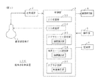
図1は、実施例1に係る超音波診断装置100の構成説明図である。
この超音波診断装置100は、電子走査による2D走査および電動走査(モータによる走査)または電子走査による3D走査が可能な超音波探触子1と、超音波探触子1を駆動して被検体内を超音波ビームで2D走査および3D走査する送受信部2と、制御部3と、2D画像等を表示する画像表示部4と、操作者が指示やデータを与えるための操作部5と、2D画像等を記録する記録部6とを具備している。
FIG. 1 is an explanatory diagram of a configuration of an ultrasonic
This ultrasonic
制御部3の2D走査部31は、2D走査を制御し、2Dデータを記憶し、2D画像を作成する。
3D走査部32は、3D走査を制御し、3Dデータを記憶し、3Dデータを所定の投影方向に投影した3D画像の作成を行う。
ドプラカーソル設定部33は、後述するドプラカーソル設定処理を実行する。2Dデータと3Dデータの相関をとって位置関係を補正する相関補正部を含んでいる。
角度カーソル設定部34は、後述する角度カーソル設定処理を実行する。2Dデータと3Dデータの相関をとって位置関係を補正する相関補正部を含んでいる。
ドプラ計測部35は、ドプラカーソルの位置をドプラ計測点として流速をドプラ計測し、流速分布画像(流速分布の時間変化のグラフ)を作成する。ドプラ計測した結果を超音波ビームと角度カーソルの成す角度で補正する角度補正部を含んでいる。
The
The
The Doppler
The angle cursor setting unit 34 executes an angle cursor setting process to be described later. A correlation correction unit that corrects the positional relationship by correlating 2D data and 3D data is included.
The Doppler measurement unit 35 performs Doppler measurement of the flow velocity using the position of the Doppler cursor as the Doppler measurement point, and creates a flow velocity distribution image (a graph of time variation of the flow velocity distribution). An angle correction unit that corrects the Doppler measurement result with an angle formed by the ultrasonic beam and the angle cursor is included.
図2は、ドプラカーソル設定部33によるドプラカーソル設定処理を示すフロー図である。
ステップS1では、2D走査モードにする。すなわち、2D走査部31で、2D走査による2Dデータを得て記憶し、2D画像を作成する。そして、2D画像を画像表示部4に表示する。なお、2D走査モードでの2D走査面の位置は、予め設定されているデフォルトの走査面の位置とする。
FIG. 2 is a flowchart showing the Doppler cursor setting process by the Doppler
In step S1, the 2D scanning mode is set. That is, the
ステップS2では、図3に示すように、2D画像G1上にドプラカーソルKdを表示する。最初にドプラカーソルKdを表示する位置は、予め設定されたデフォルトの位置または2Dデータ(2D画像でもよい)を解析して抽出した最も大きい血管の位置とする。そして、操作者によるドプラカーソルKdの位置変更操作を受け付ける。なお、ドプラカーソルKdの位置は、2D走査面上の位置として規定されるものとする。 In step S2, as shown in FIG. 3, a Doppler cursor Kd is displayed on the 2D image G1. The position where the Doppler cursor Kd is first displayed is the default position set in advance or the position of the largest blood vessel extracted by analyzing 2D data (or a 2D image). Then, the position change operation of the Doppler cursor Kd by the operator is accepted. Note that the position of the Doppler cursor Kd is defined as a position on the 2D scanning plane.
ステップS3では、操作者がドプラカーソルの位置を確定する操作をしたらステップS12へ進み、その操作をしない場合はステップS4へ進む。
ステップS4では、操作者が3D画像によるドプラカーソルの位置の確認をする操作をしたらステップS6へ進み、その操作をしない場合はステップS3に戻る。
In step S3, if the operator performs an operation to confirm the position of the Doppler cursor, the process proceeds to step S12, and if not, the process proceeds to step S4.
In step S4, if the operator performs an operation for confirming the position of the Doppler cursor by the 3D image, the process proceeds to step S6. If not, the process returns to step S3.
ステップS6では、3D走査部32で3D走査による3Dデータを得て記憶する。
図4に、3DデータVを概念的に示す。図4の(a)は正面図、(b)は側面図、(c)は上面図である。fは、血管である。
In step S6, the
FIG. 4 conceptually shows the 3D data V. 4A is a front view, FIG. 4B is a side view, and FIG. 4C is a top view. f is a blood vessel.
ステップS7では、2D走査部31で2D走査による2Dデータを得て記憶する。このときの2D走査面の位置は、予め設定されているデフォルトの走査面の位置とする。
In step S7,
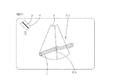
ステップS8では、3Dデータと2D走査面の位置とドプラカーソルを現在の投影方向に投影した3D画像を表示する。なお、3Dデータと2Dデータの相関により2D走査面の位置の補正を行う。また、最初の投影方向は、予め設定されているデフォルトの方向とする。
図5に、3D画像G2を例示する。pは2D走査面の位置である。画面の左上に、3次元データVの平面図と、2D走査面の位置Pと、投影方向を示す矢印とが表示されている。
In step S8, 3D data, the position of the 2D scanning plane, and a 3D image obtained by projecting the Doppler cursor in the current projection direction are displayed. The position of the 2D scanning plane is corrected based on the correlation between 3D data and 2D data. In addition, the initial projection direction is a preset default direction.
FIG. 5 illustrates a 3D image G2. p is the position of the 2D scanning plane. A plan view of the three-dimensional data V, the position P of the 2D scanning plane, and an arrow indicating the projection direction are displayed on the upper left of the screen.
ステップS9では、操作者がドプラカーソルの位置を確定する操作をしたらステップS12へ進み、その操作をしない場合はステップS10へ進む。
ステップS10では、操作者による投影方向の変更とドプラカーソルの位置変更とを受け付ける。
ステップS11では、操作者の指示に応じて投影方向の変更とドプラカーソルの位置変更とを行う。そして、ステップS7に戻る。
図6に、投影方向の変更をした後の3D画像G2を例示する。なお、この例では、投影方向を水平方向に回転しているが、垂直方向に回転させてもよい。
In step S9, if the operator performs an operation to confirm the position of the Doppler cursor, the process proceeds to step S12. If not, the process proceeds to step S10.
In step S10, a change in projection direction and a change in position of the Doppler cursor by the operator are accepted.
In step S11, the projection direction is changed and the position of the Doppler cursor is changed in accordance with an instruction from the operator. Then, the process returns to step S7.
FIG. 6 illustrates a 3D image G2 after changing the projection direction. In this example, the projection direction is rotated in the horizontal direction, but may be rotated in the vertical direction.
ステップS12では、現在の2D走査面の位置とドプラカーソルの位置を記憶する。そして、処理を終了する。 In step S12, the current 2D scanning plane position and Doppler cursor position are stored. Then, the process ends.
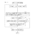
図7は、角度カーソル設定部34による角度カーソル設定処理のフロー図である。
ステップA1では、3D走査部32で3D走査による3Dデータを得て記憶する。
FIG. 7 is a flowchart of angle cursor setting processing by the angle cursor setting unit 34.
In step A1, the
ステップA2では、2D走査部31で2D走査による2Dデータを得て記憶する。このときの2D走査面の位置は、ドプラカーソル設定時に記憶した位置とする。
In step A2,
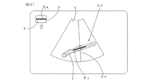
ステップA3では、3Dデータと2D走査面の位置とドプラカーソルと角度カーソルとを現在の投影方向に投影した3D画像を表示する。なお、3Dデータと2Dデータの相関により2D走査面の位置の補正を行う。また、最初の投影方向は、予め設定されているデフォルトの方向とする。また、ドプラカーソルの位置は、ドプラカーソル設定時に記憶した位置とする。さらに、角度カーソルの中心がドプラ観測点を通るものとし、最初の方向は予め設定されているデフォルトの方向または3Dデータを解析して抽出したドプラ計測点を通る血管の方向とする。
図8に、3D画像G3を例示する。Kaは角度カーソルである。画面の左上に、3次元データVの平面図と、2D走査面の位置Pと、投影方向を示す矢印と、角度カーソルKaの平面図KAとが表示されている。
In step A3, a 3D image obtained by projecting the 3D data, the position of the 2D scanning plane, the Doppler cursor, and the angle cursor in the current projection direction is displayed. The position of the 2D scanning plane is corrected based on the correlation between 3D data and 2D data. In addition, the initial projection direction is a preset default direction. The position of the Doppler cursor is the position stored when the Doppler cursor is set. Further, it is assumed that the center of the angle cursor passes through the Doppler observation point, and the first direction is a default direction set in advance or the direction of the blood vessel passing through the Doppler measurement point extracted by analyzing 3D data.
FIG. 8 illustrates a 3D image G3. Ka is an angle cursor. On the upper left of the screen, a plan view of the three-dimensional data V, a position P of the 2D scanning plane, an arrow indicating the projection direction, and a plan view KA of the angle cursor Ka are displayed.
ステップA4では、操作者が角度カーソルの位置を確定する操作をしたらステップA7へ進み、その操作をしない場合はステップA5へ進む。
ステップA5では、操作者による投影方向の変更と角度カーソルの方向変更とを受け付ける。
ステップA6では、操作者の指示に応じて投影方向の変更と角度カーソルの方向変更とを行う。そして、ステップA2に戻る。
図9に、投影方向の変更をした後の3D画像G4を例示する。なお、この例では、投影方向を水平方向に回転しているが、垂直方向に回転させてもよい。
In step A4, if the operator performs an operation to confirm the position of the angle cursor, the process proceeds to step A7, and if not, the process proceeds to step A5.
In step A5, a change in projection direction and an angle cursor direction change by the operator are accepted.
In step A6, the projection direction is changed and the direction of the angle cursor is changed in accordance with an instruction from the operator. Then, the process returns to step A2.
FIG. 9 illustrates the 3D image G4 after changing the projection direction. In this example, the projection direction is rotated in the horizontal direction, but may be rotated in the vertical direction.
ステップA7では、現在の角度カーソルの方向を記憶する。そして、処理を終了する。 In step A7, the current angle cursor direction is stored. Then, the process ends.
図10は、ドプラ計測部35によるドプラ流速測定処理を示すフロー図である。
ステップF1では、ドプラカーソルで規定されたドプラ計測点でドプラ計測を行って血流の流速を得る。この計測結果は実際の流速の超音波ビーム方向成分であるから、超音波ビームの方向と角度カーソルの方向の成す角度により流速補正を行って実際の流速を得る。そして、流速分布画像を作成し、画像表示部4に表示する。
ステップF2では、操作者が処理を終了する操作をしたら処理を終了し、そうでなければステップF1に戻る。
FIG. 10 is a flowchart showing the Doppler flow rate measurement process by the Doppler measurement unit 35.
In Step F1, Doppler measurement is performed at a Doppler measurement point defined by a Doppler cursor to obtain a blood flow velocity. Since the measurement result is the ultrasonic beam direction component of the actual flow velocity, the flow velocity is corrected by the angle formed by the direction of the ultrasonic beam and the direction of the angle cursor to obtain the actual flow velocity. Then, a flow velocity distribution image is created and displayed on the
In step F2, if the operator performs an operation to end the process, the process ends. If not, the process returns to step F1.
実施例1の超音波診断装置100によれば、操作者が投影方向を変更する指示を与えることによって視線方向を変えた3D画像上でドプラカーソルや角度カーソルを見ることが出来る。よって、ドプラカーソルや角度カーソルが的確に設定されているか否かを容易に確認することが出来る。
According to the ultrasonic
実施例1のドプラカーソル設定処理では、2D走査面の位置がリアルタイムに更新されているが、3Dデータはリアルタイムに更新されていなかった。
実施例2のドプラカーソル設定処理では、3Dデータがリアルタイムに更新され、2D走査面の位置はリアルタイムに更新されない。
In the Doppler cursor setting process of the first embodiment, the position of the 2D scanning plane is updated in real time, but the 3D data is not updated in real time.
In the Doppler cursor setting process of the second embodiment, 3D data is updated in real time, and the position of the 2D scanning plane is not updated in real time.
図11は、実施例2に掛かるドプラカーソル設定処理を示すフロー図である。
ステップS1〜S3は、実施例1と同じである。
ステップS4では、操作者が3D画像によるドプラカーソルの位置の確認をする操作をしたらステップS5へ進み、その操作をしない場合はステップS3に戻る。
ステップS5では、現在の2D走査面の位置を記憶する。そして、ステップS6へ進む。
FIG. 11 is a flowchart illustrating the Doppler cursor setting process according to the second embodiment.
Steps S1 to S3 are the same as those in the first embodiment.
In step S4, if the operator performs an operation for confirming the position of the Doppler cursor using the 3D image, the process proceeds to step S5. If not, the process returns to step S3.
In step S5, the current position of the 2D scanning plane is stored. Then, the process proceeds to step S6.
ステップS6では、3D走査部32で3D走査による3Dデータを得て記憶する。そして、ステップS8へ進む。
ステップS8〜S10は、実施例1と同じである。
ステップS11では、操作者の指示に応じて投影方向の変更とドプラカーソルの位置変更とを行う。そして、ステップS6に戻る。
In step S6, the
Steps S8 to S10 are the same as those in the first embodiment.
In step S11, the projection direction is changed and the position of the Doppler cursor is changed in accordance with an instruction from the operator. Then, the process returns to step S6.
実施例1の角度カーソル設定処理では、2D走査面の位置がリアルタイムに更新されているが、3Dデータはリアルタイムに更新されていなかった。
実施例3の角度カーソル設定処理では、3Dデータがリアルタイムに更新され、2D走査面の位置はリアルタイムに更新されない。
In the angle cursor setting process according to the first embodiment, the position of the 2D scanning plane is updated in real time, but the 3D data is not updated in real time.
In the angle cursor setting process according to the third embodiment, 3D data is updated in real time, and the position of the 2D scanning plane is not updated in real time.
図12は、実施例3に掛かる角度カーソル設定処理を示すフロー図である。
ステップA1では、3D走査部32で3D走査による3Dデータを得て記憶する。そして、ステップA3へ進む。
ステップA3〜A5は、実施例1と同じである。
ステップA6では、操作者の指示に応じて投影方向の変更と角度カーソルの方向変更とを行う。そして、ステップA1に戻る。
ステップA7は、実施例1と同じである。
FIG. 12 is a flowchart illustrating the angle cursor setting process according to the third embodiment.
In step A1, the
Steps A3 to A5 are the same as those in the first embodiment.
In step A6, the projection direction is changed and the direction of the angle cursor is changed in accordance with an instruction from the operator. Then, the process returns to step A1.
Step A7 is the same as that in the first embodiment.
実施例1のステップS11からステップS6に戻ってもよい。この場合、2D走査面の位置および3Dデータがリアルタイムに更新される。 You may return from step S11 of Example 1 to step S6. In this case, the position of the 2D scanning plane and the 3D data are updated in real time.
実施例1のステップA6からステップA1に戻ってもよい。この場合、2D走査面の位置および3Dデータがリアルタイムに更新される。 You may return from step A6 of Example 1 to step A1. In this case, the position of the 2D scanning plane and the 3D data are updated in real time.
本発明の超音波診断装置は、血流速度のドプラ計測に利用できる。 The ultrasonic diagnostic apparatus of the present invention can be used for Doppler measurement of blood flow velocity.
1 超音波探触子
2 送受信部
3 制御部
4 画像表示部
5 操作部
100 超音波診断装置
Kd ドプラカーソル
Ka 角度カーソル
V 3Dデータ
DESCRIPTION OF
Claims (7)
前記超音波探触子を駆動して被検体内を超音波ビームで2D走査および3D走査を行う送受信手段と、
3D走査を行って得た3Dデータを記憶する記憶手段と、
前記記憶手段に記憶された3Dデータと、前記3Dデータが形成する3D空間内に存在する、ドプラ計測のための2D走査面のデータ及びドプラカーソルのデータとを用いて、所定の視線方向から見た3D画像を表示装置に表示する表示手段と、
操作者の指示を受け付けて該指示に応じて前記視線方向および前記ドプラカーソルの位置を変更する指示対応変更手段と、
位置が確定された、前記ドプラ計測のための2D走査面のデータ及び前記ドプラカーソルを用いてドプラ計測を行うドプラ計測手段とを具備し、
前記送受信手段は、ドプラ計測前に3D走査を行った後、3D走査をリアルタイムに行わず、2D走査をリアルタイムに行って2D走査面のデータを順次更新してドプラ計測を行うことを特徴とする超音波診断装置。 An ultrasonic probe capable of 2D scanning by electronic scanning and 3D scanning by electric scanning or electronic scanning;
Transmitting / receiving means for driving the ultrasonic probe to perform 2D scanning and 3D scanning with an ultrasonic beam in the subject;
Storage means for storing 3D data obtained by performing 3D scanning;
Using 3D data stored in the storage means and 2D scanning plane data and Doppler cursor data for Doppler measurement existing in the 3D space formed by the 3D data, the data is viewed from a predetermined line-of-sight direction. Display means for displaying the 3D image on the display device;
An instruction response changing unit that receives an operator's instruction and changes the line-of-sight direction and the position of the Doppler cursor according to the instruction;
2D scanning plane data for the Doppler measurement, the position of which has been determined, and Doppler measurement means for performing Doppler measurement using the Doppler cursor,
The transmission / reception means performs 3D scanning before Doppler measurement, performs 3D scanning in real time, performs 2D scanning in real time, and sequentially updates data on the 2D scanning surface to perform Doppler measurement. Ultrasound diagnostic device.
前記ドプラカーソルの最初の位置は、予め設定された位置又はデータから抽出した血管の位置であることを特徴とする超音波診断装置。 The ultrasonic diagnostic apparatus according to claim 1,
An ultrasonic diagnostic apparatus, wherein an initial position of the Doppler cursor is a preset position or a blood vessel position extracted from data.
前記表示手段は、更にドプラ観測点での血管の方向を表す角度カーソルのデータとを用いて、所定の視線方向から見た3D画像を表示装置に表示し、
前記指示対応変更手段は、更に操作者の指示を受け付けて該指示に応じて前記角度カーソルの方向を変更し、
前記ドプラ計測での超音波ビームの方向と確定した角度カーソルの方向との成す角度により前記ドプラ計測の結果を補正する補正手段とを具備したことを特徴とする超音波診断装置。 The ultrasonic diagnostic apparatus according to claim 1 or 2,
The display means further displays a 3D image viewed from a predetermined line-of-sight direction on a display device using data of an angle cursor representing the direction of a blood vessel at a Doppler observation point,
The instruction correspondence changing means further receives an operator instruction and changes the direction of the angle cursor in accordance with the instruction,
An ultrasonic diagnostic apparatus comprising: correction means for correcting a result of the Doppler measurement based on an angle formed by the direction of the ultrasonic beam in the Doppler measurement and the direction of the determined angle cursor.
前記角度カーソルの最初の方向は、予め設定された方向又は3Dデータから抽出した血管の方向であることを特徴とする超音波診断装置。 The ultrasonic diagnostic apparatus according to claim 3.
The ultrasonic diagnostic apparatus, wherein the first direction of the angle cursor is a preset direction or a direction of a blood vessel extracted from 3D data.
前記表示手段は、3Dデータにおける前記ドプラ計測のための2D走査面位置及び前記視線方向を前記表示装置に表示することを特徴とする超音波診断装置。 In the ultrasonic diagnostic apparatus according to any one of claims 1 to 4,
The ultrasonic diagnostic apparatus, wherein the display means displays a 2D scanning plane position and the line-of-sight direction for the Doppler measurement in 3D data on the display device.
前記3Dデータと前記リアルタイムに2D走査して得たリアルタイム2Dデータとの相関により前記2D走査面の位置を補正する位置補正手段を具備したことを特徴とする超音波診断装置。 In the ultrasonic diagnostic apparatus according to any one of claims 1 to 5,
An ultrasonic diagnostic apparatus comprising position correction means for correcting the position of the 2D scanning plane based on the correlation between the 3D data and the real-time 2D data obtained by performing the 2D scanning in real time.
前記ドプラ計測のための2D走査面の位置は、操作者が指定した2D走査面の位置であることを特徴とする超音波診断装置。 The ultrasonic diagnostic apparatus according to any one of claims 1 to 6,
2. The ultrasonic diagnostic apparatus according to claim 1, wherein the position of the 2D scanning plane for Doppler measurement is the position of the 2D scanning plane designated by the operator.
Priority Applications (2)
| Application Number | Priority Date | Filing Date | Title |
|---|---|---|---|
| JP2006238878A JP4886432B2 (en) | 2006-09-04 | 2006-09-04 | Ultrasonic diagnostic equipment |
| US11/848,771 US7905837B2 (en) | 2006-09-04 | 2007-08-31 | Ultrasound diagnostic apparatus |
Applications Claiming Priority (1)
| Application Number | Priority Date | Filing Date | Title |
|---|---|---|---|
| JP2006238878A JP4886432B2 (en) | 2006-09-04 | 2006-09-04 | Ultrasonic diagnostic equipment |
Publications (3)
| Publication Number | Publication Date |
|---|---|
| JP2008055101A JP2008055101A (en) | 2008-03-13 |
| JP2008055101A5 JP2008055101A5 (en) | 2011-05-26 |
| JP4886432B2 true JP4886432B2 (en) | 2012-02-29 |
Family
ID=39152754
Family Applications (1)
| Application Number | Title | Priority Date | Filing Date |
|---|---|---|---|
| JP2006238878A Active JP4886432B2 (en) | 2006-09-04 | 2006-09-04 | Ultrasonic diagnostic equipment |
Country Status (2)
| Country | Link |
|---|---|
| US (1) | US7905837B2 (en) |
| JP (1) | JP4886432B2 (en) |
Families Citing this family (14)
| Publication number | Priority date | Publication date | Assignee | Title |
|---|---|---|---|---|
| US9456766B2 (en) | 2007-11-26 | 2016-10-04 | C. R. Bard, Inc. | Apparatus for use with needle insertion guidance system |
| US9521961B2 (en) | 2007-11-26 | 2016-12-20 | C. R. Bard, Inc. | Systems and methods for guiding a medical instrument |
| EP2992825B1 (en) | 2007-11-26 | 2017-11-01 | C.R. Bard Inc. | Integrated system for intravascular placement of a catheter |
| US8781555B2 (en) | 2007-11-26 | 2014-07-15 | C. R. Bard, Inc. | System for placement of a catheter including a signal-generating stylet |
| US9532724B2 (en) | 2009-06-12 | 2017-01-03 | Bard Access Systems, Inc. | Apparatus and method for catheter navigation using endovascular energy mapping |
| US20110028845A1 (en) * | 2009-07-31 | 2011-02-03 | Bruno Hans Haider | Reconfigurable Ultrasound Array with Low Noise CW Processing |
| JP6081299B2 (en) * | 2013-06-13 | 2017-02-15 | 東芝メディカルシステムズ株式会社 | Ultrasonic diagnostic equipment |
| EP2989992B1 (en) | 2014-09-01 | 2022-11-16 | Samsung Medison Co., Ltd. | Medical imaging apparatus and method of generating medical image |
| US11020563B2 (en) | 2016-07-14 | 2021-06-01 | C. R. Bard, Inc. | Automated catheter-to-vessel size comparison tool and related methods |
| US10992079B2 (en) | 2018-10-16 | 2021-04-27 | Bard Access Systems, Inc. | Safety-equipped connection systems and methods thereof for establishing electrical connections |
| EP4025132A4 (en) | 2019-09-20 | 2023-10-04 | Bard Access Systems, Inc. | Automatic vessel detection tools and methods |
| WO2022020351A1 (en) | 2020-07-21 | 2022-01-27 | Bard Access Systems, Inc. | System, method and apparatus for magnetic tracking of ultrasound probe and generation of 3d visualization thereof |
| EP4203801A1 (en) | 2020-09-03 | 2023-07-05 | Bard Access Systems, Inc. | Portable ultrasound systems and methods |
| WO2022067101A1 (en) | 2020-09-25 | 2022-03-31 | Bard Access Systems, Inc. | Minimum catheter length tool |
Family Cites Families (11)
| Publication number | Priority date | Publication date | Assignee | Title |
|---|---|---|---|---|
| JPH06217975A (en) * | 1993-01-28 | 1994-08-09 | Toshiba Medical Eng Co Ltd | Ultrasonic doppler diagnostic device |
| US5682896A (en) | 1996-03-28 | 1997-11-04 | Diasonics Ultrasound, Inc. | Method and apparatus for generating volume flow measurement |
| JP3936450B2 (en) * | 1997-11-25 | 2007-06-27 | ジーイー横河メディカルシステム株式会社 | Projection image generation apparatus and medical image apparatus |
| JP4282130B2 (en) * | 1999-01-19 | 2009-06-17 | 株式会社東芝 | 3D ultrasonic diagnostic equipment |
| JP4659950B2 (en) * | 1999-08-20 | 2011-03-30 | 株式会社東芝 | Ultrasonic diagnostic equipment |
| US6599244B1 (en) | 1999-12-23 | 2003-07-29 | Siemens Medical Solutions, Usa, Inc. | Ultrasound system and method for direct manipulation interface |
| US6390984B1 (en) | 2000-09-14 | 2002-05-21 | Ge Medical Systems Global Technology Company, Llc | Method and apparatus for locking sample volume onto moving vessel in pulsed doppler ultrasound imaging |
| JP2003061958A (en) * | 2001-06-15 | 2003-03-04 | Toshiba Medical System Co Ltd | Ultrasonic diagnostic apparatus |
| JP4113485B2 (en) * | 2003-09-24 | 2008-07-09 | アロカ株式会社 | Ultrasonic image processing device |
| JP4177217B2 (en) * | 2003-09-24 | 2008-11-05 | アロカ株式会社 | Ultrasonic diagnostic equipment |
| JP4634814B2 (en) * | 2005-02-03 | 2011-02-16 | 株式会社東芝 | Ultrasonic diagnostic equipment |
-
2006
- 2006-09-04 JP JP2006238878A patent/JP4886432B2/en active Active
-
2007
- 2007-08-31 US US11/848,771 patent/US7905837B2/en active Active
Also Published As
| Publication number | Publication date |
|---|---|
| US7905837B2 (en) | 2011-03-15 |
| JP2008055101A (en) | 2008-03-13 |
| US20080058645A1 (en) | 2008-03-06 |
Similar Documents
| Publication | Publication Date | Title |
|---|---|---|
| JP4886432B2 (en) | Ultrasonic diagnostic equipment | |
| US8617075B2 (en) | Ultrasonic diagnostic apparatus and ultrasonic imaging method | |
| US8585600B2 (en) | Ultrasound volume probe navigation and control method and device | |
| CN108784735B (en) | Ultrasound imaging system and method for displaying acquisition quality level | |
| JP6063454B2 (en) | Ultrasonic diagnostic apparatus and locus display method | |
| JP2008055101A5 (en) | ||
| JP4958455B2 (en) | Ultrasonic diagnostic equipment | |
| JP5636467B2 (en) | Ultrasonic diagnostic equipment | |
| JPH09192131A (en) | Real-time biplane image display method for ultrasonic diagnostic system | |
| JP2016523164A (en) | Delineation of rib obstructions in anatomically intelligent echocardiography | |
| KR101656127B1 (en) | Measuring apparatus and program for controlling the same | |
| JP2007202829A (en) | Ultrasonic diagnostic system | |
| JP2014121434A (en) | Ultrasonic diagnostic apparatus and collection state display method of the same | |
| JP4865575B2 (en) | Ultrasonic diagnostic equipment | |
| JP3410404B2 (en) | Ultrasound diagnostic equipment | |
| WO2016190328A1 (en) | Ultrasonic diagnostic device | |
| JP2009261520A (en) | Ultrasonic imaging system | |
| JP2007195854A (en) | Ultrasonic diagnostic apparatus | |
| US8942453B2 (en) | Ultrasonograph and method of diagnosis using same | |
| JP2009011449A (en) | Ultrasonic diagnostic equipment | |
| JP6082783B2 (en) | Ultrasonic diagnostic equipment | |
| JP2006081640A (en) | Ultrasonic imaging device, image processor and program | |
| KR102598211B1 (en) | Ultrasound scanner for measuring urine volume in a bladder | |
| KR102615722B1 (en) | Ultrasound scanner and method of guiding aim | |
| JP5809302B2 (en) | Ultrasonic diagnostic equipment |
Legal Events
| Date | Code | Title | Description |
|---|---|---|---|
| A625 | Written request for application examination (by other person) |
Free format text: JAPANESE INTERMEDIATE CODE: A625 Effective date: 20090114 |
|
| A521 | Request for written amendment filed |
Free format text: JAPANESE INTERMEDIATE CODE: A523 Effective date: 20110412 |
|
| A977 | Report on retrieval |
Free format text: JAPANESE INTERMEDIATE CODE: A971007 Effective date: 20110517 |
|
| A131 | Notification of reasons for refusal |
Free format text: JAPANESE INTERMEDIATE CODE: A131 Effective date: 20110531 |
|
| A521 | Request for written amendment filed |
Free format text: JAPANESE INTERMEDIATE CODE: A523 Effective date: 20110829 |
|
| TRDD | Decision of grant or rejection written | ||
| A01 | Written decision to grant a patent or to grant a registration (utility model) |
Free format text: JAPANESE INTERMEDIATE CODE: A01 Effective date: 20111122 |
|
| A01 | Written decision to grant a patent or to grant a registration (utility model) |
Free format text: JAPANESE INTERMEDIATE CODE: A01 |
|
| A61 | First payment of annual fees (during grant procedure) |
Free format text: JAPANESE INTERMEDIATE CODE: A61 Effective date: 20111209 |
|
| FPAY | Renewal fee payment (event date is renewal date of database) |
Free format text: PAYMENT UNTIL: 20141216 Year of fee payment: 3 |
|
| R150 | Certificate of patent or registration of utility model |
Ref document number: 4886432 Country of ref document: JP Free format text: JAPANESE INTERMEDIATE CODE: R150 Free format text: JAPANESE INTERMEDIATE CODE: R150 |
|
| FPAY | Renewal fee payment (event date is renewal date of database) |
Free format text: PAYMENT UNTIL: 20141216 Year of fee payment: 3 |
|
| R250 | Receipt of annual fees |
Free format text: JAPANESE INTERMEDIATE CODE: R250 |
|
| R250 | Receipt of annual fees |
Free format text: JAPANESE INTERMEDIATE CODE: R250 |
|
| R250 | Receipt of annual fees |
Free format text: JAPANESE INTERMEDIATE CODE: R250 |
|
| R250 | Receipt of annual fees |
Free format text: JAPANESE INTERMEDIATE CODE: R250 |
|
| R250 | Receipt of annual fees |
Free format text: JAPANESE INTERMEDIATE CODE: R250 |
|
| R250 | Receipt of annual fees |
Free format text: JAPANESE INTERMEDIATE CODE: R250 |
|
| R250 | Receipt of annual fees |
Free format text: JAPANESE INTERMEDIATE CODE: R250 |
|
| R250 | Receipt of annual fees |
Free format text: JAPANESE INTERMEDIATE CODE: R250 |
|
| R250 | Receipt of annual fees |
Free format text: JAPANESE INTERMEDIATE CODE: R250 |
|
| R250 | Receipt of annual fees |
Free format text: JAPANESE INTERMEDIATE CODE: R250 |