EP1673539B1 - Evacuation apparatus - Google Patents
Evacuation apparatus Download PDFInfo
- Publication number
- EP1673539B1 EP1673539B1 EP04792713.2A EP04792713A EP1673539B1 EP 1673539 B1 EP1673539 B1 EP 1673539B1 EP 04792713 A EP04792713 A EP 04792713A EP 1673539 B1 EP1673539 B1 EP 1673539B1
- Authority
- EP
- European Patent Office
- Prior art keywords
- pump
- rotors
- vacuum pump
- rotor
- multistage
- Prior art date
- Legal status (The legal status is an assumption and is not a legal conclusion. Google has not performed a legal analysis and makes no representation as to the accuracy of the status listed.)
- Active
Links
- 238000000034 method Methods 0.000 claims description 49
- 239000007789 gas Substances 0.000 description 67
- 239000000758 substrate Substances 0.000 description 18
- 238000005086 pumping Methods 0.000 description 11
- 239000006227 byproduct Substances 0.000 description 8
- 238000001816 cooling Methods 0.000 description 4
- 238000005530 etching Methods 0.000 description 4
- 238000006073 displacement reaction Methods 0.000 description 3
- IJGRMHOSHXDMSA-UHFFFAOYSA-N Atomic nitrogen Chemical compound N#N IJGRMHOSHXDMSA-UHFFFAOYSA-N 0.000 description 2
- 238000004140 cleaning Methods 0.000 description 2
- 230000006835 compression Effects 0.000 description 2
- 238000007906 compression Methods 0.000 description 2
- 239000000110 cooling liquid Substances 0.000 description 2
- 239000004973 liquid crystal related substance Substances 0.000 description 2
- 239000004065 semiconductor Substances 0.000 description 2
- 230000001360 synchronised effect Effects 0.000 description 2
- 238000011144 upstream manufacturing Methods 0.000 description 2
- 230000003197 catalytic effect Effects 0.000 description 1
- 238000002485 combustion reaction Methods 0.000 description 1
- 230000020169 heat generation Effects 0.000 description 1
- 239000011261 inert gas Substances 0.000 description 1
- 239000000314 lubricant Substances 0.000 description 1
- 229910052757 nitrogen Inorganic materials 0.000 description 1
- 230000003584 silencer Effects 0.000 description 1
Images


Classifications
-
- F—MECHANICAL ENGINEERING; LIGHTING; HEATING; WEAPONS; BLASTING
- F04—POSITIVE - DISPLACEMENT MACHINES FOR LIQUIDS; PUMPS FOR LIQUIDS OR ELASTIC FLUIDS
- F04C—ROTARY-PISTON, OR OSCILLATING-PISTON, POSITIVE-DISPLACEMENT MACHINES FOR LIQUIDS; ROTARY-PISTON, OR OSCILLATING-PISTON, POSITIVE-DISPLACEMENT PUMPS
- F04C28/00—Control of, monitoring of, or safety arrangements for, pumps or pumping installations specially adapted for elastic fluids
- F04C28/08—Control of, monitoring of, or safety arrangements for, pumps or pumping installations specially adapted for elastic fluids characterised by varying the rotational speed
-
- C—CHEMISTRY; METALLURGY
- C23—COATING METALLIC MATERIAL; COATING MATERIAL WITH METALLIC MATERIAL; CHEMICAL SURFACE TREATMENT; DIFFUSION TREATMENT OF METALLIC MATERIAL; COATING BY VACUUM EVAPORATION, BY SPUTTERING, BY ION IMPLANTATION OR BY CHEMICAL VAPOUR DEPOSITION, IN GENERAL; INHIBITING CORROSION OF METALLIC MATERIAL OR INCRUSTATION IN GENERAL
- C23C—COATING METALLIC MATERIAL; COATING MATERIAL WITH METALLIC MATERIAL; SURFACE TREATMENT OF METALLIC MATERIAL BY DIFFUSION INTO THE SURFACE, BY CHEMICAL CONVERSION OR SUBSTITUTION; COATING BY VACUUM EVAPORATION, BY SPUTTERING, BY ION IMPLANTATION OR BY CHEMICAL VAPOUR DEPOSITION, IN GENERAL
- C23C16/00—Chemical coating by decomposition of gaseous compounds, without leaving reaction products of surface material in the coating, i.e. chemical vapour deposition [CVD] processes
- C23C16/44—Chemical coating by decomposition of gaseous compounds, without leaving reaction products of surface material in the coating, i.e. chemical vapour deposition [CVD] processes characterised by the method of coating
- C23C16/4412—Details relating to the exhausts, e.g. pumps, filters, scrubbers, particle traps
-
- F—MECHANICAL ENGINEERING; LIGHTING; HEATING; WEAPONS; BLASTING
- F01—MACHINES OR ENGINES IN GENERAL; ENGINE PLANTS IN GENERAL; STEAM ENGINES
- F01C—ROTARY-PISTON OR OSCILLATING-PISTON MACHINES OR ENGINES
- F01C21/00—Component parts, details or accessories not provided for in groups F01C1/00 - F01C20/00
- F01C21/007—General arrangements of parts; Frames and supporting elements
-
- F—MECHANICAL ENGINEERING; LIGHTING; HEATING; WEAPONS; BLASTING
- F04—POSITIVE - DISPLACEMENT MACHINES FOR LIQUIDS; PUMPS FOR LIQUIDS OR ELASTIC FLUIDS
- F04C—ROTARY-PISTON, OR OSCILLATING-PISTON, POSITIVE-DISPLACEMENT MACHINES FOR LIQUIDS; ROTARY-PISTON, OR OSCILLATING-PISTON, POSITIVE-DISPLACEMENT PUMPS
- F04C18/00—Rotary-piston pumps specially adapted for elastic fluids
- F04C18/08—Rotary-piston pumps specially adapted for elastic fluids of intermeshing-engagement type, i.e. with engagement of co-operating members similar to that of toothed gearing
- F04C18/12—Rotary-piston pumps specially adapted for elastic fluids of intermeshing-engagement type, i.e. with engagement of co-operating members similar to that of toothed gearing of other than internal-axis type
- F04C18/126—Rotary-piston pumps specially adapted for elastic fluids of intermeshing-engagement type, i.e. with engagement of co-operating members similar to that of toothed gearing of other than internal-axis type with radially from the rotor body extending elements, not necessarily co-operating with corresponding recesses in the other rotor, e.g. lobes, Roots type
-
- F—MECHANICAL ENGINEERING; LIGHTING; HEATING; WEAPONS; BLASTING
- F04—POSITIVE - DISPLACEMENT MACHINES FOR LIQUIDS; PUMPS FOR LIQUIDS OR ELASTIC FLUIDS
- F04C—ROTARY-PISTON, OR OSCILLATING-PISTON, POSITIVE-DISPLACEMENT MACHINES FOR LIQUIDS; ROTARY-PISTON, OR OSCILLATING-PISTON, POSITIVE-DISPLACEMENT PUMPS
- F04C18/00—Rotary-piston pumps specially adapted for elastic fluids
- F04C18/08—Rotary-piston pumps specially adapted for elastic fluids of intermeshing-engagement type, i.e. with engagement of co-operating members similar to that of toothed gearing
- F04C18/12—Rotary-piston pumps specially adapted for elastic fluids of intermeshing-engagement type, i.e. with engagement of co-operating members similar to that of toothed gearing of other than internal-axis type
- F04C18/14—Rotary-piston pumps specially adapted for elastic fluids of intermeshing-engagement type, i.e. with engagement of co-operating members similar to that of toothed gearing of other than internal-axis type with toothed rotary pistons
- F04C18/16—Rotary-piston pumps specially adapted for elastic fluids of intermeshing-engagement type, i.e. with engagement of co-operating members similar to that of toothed gearing of other than internal-axis type with toothed rotary pistons with helical teeth, e.g. chevron-shaped, screw type
-
- F—MECHANICAL ENGINEERING; LIGHTING; HEATING; WEAPONS; BLASTING
- F04—POSITIVE - DISPLACEMENT MACHINES FOR LIQUIDS; PUMPS FOR LIQUIDS OR ELASTIC FLUIDS
- F04C—ROTARY-PISTON, OR OSCILLATING-PISTON, POSITIVE-DISPLACEMENT MACHINES FOR LIQUIDS; ROTARY-PISTON, OR OSCILLATING-PISTON, POSITIVE-DISPLACEMENT PUMPS
- F04C23/00—Combinations of two or more pumps, each being of rotary-piston or oscillating-piston type, specially adapted for elastic fluids; Pumping installations specially adapted for elastic fluids; Multi-stage pumps specially adapted for elastic fluids
- F04C23/001—Combinations of two or more pumps, each being of rotary-piston or oscillating-piston type, specially adapted for elastic fluids; Pumping installations specially adapted for elastic fluids; Multi-stage pumps specially adapted for elastic fluids of similar working principle
-
- F—MECHANICAL ENGINEERING; LIGHTING; HEATING; WEAPONS; BLASTING
- F04—POSITIVE - DISPLACEMENT MACHINES FOR LIQUIDS; PUMPS FOR LIQUIDS OR ELASTIC FLUIDS
- F04C—ROTARY-PISTON, OR OSCILLATING-PISTON, POSITIVE-DISPLACEMENT MACHINES FOR LIQUIDS; ROTARY-PISTON, OR OSCILLATING-PISTON, POSITIVE-DISPLACEMENT PUMPS
- F04C23/00—Combinations of two or more pumps, each being of rotary-piston or oscillating-piston type, specially adapted for elastic fluids; Pumping installations specially adapted for elastic fluids; Multi-stage pumps specially adapted for elastic fluids
- F04C23/005—Combinations of two or more pumps, each being of rotary-piston or oscillating-piston type, specially adapted for elastic fluids; Pumping installations specially adapted for elastic fluids; Multi-stage pumps specially adapted for elastic fluids of dissimilar working principle
-
- F—MECHANICAL ENGINEERING; LIGHTING; HEATING; WEAPONS; BLASTING
- F04—POSITIVE - DISPLACEMENT MACHINES FOR LIQUIDS; PUMPS FOR LIQUIDS OR ELASTIC FLUIDS
- F04C—ROTARY-PISTON, OR OSCILLATING-PISTON, POSITIVE-DISPLACEMENT MACHINES FOR LIQUIDS; ROTARY-PISTON, OR OSCILLATING-PISTON, POSITIVE-DISPLACEMENT PUMPS
- F04C25/00—Adaptations of pumps for special use of pumps for elastic fluids
- F04C25/02—Adaptations of pumps for special use of pumps for elastic fluids for producing high vacuum
-
- H—ELECTRICITY
- H01—ELECTRIC ELEMENTS
- H01J—ELECTRIC DISCHARGE TUBES OR DISCHARGE LAMPS
- H01J37/00—Discharge tubes with provision for introducing objects or material to be exposed to the discharge, e.g. for the purpose of examination or processing thereof
- H01J37/32—Gas-filled discharge tubes
- H01J37/32431—Constructional details of the reactor
- H01J37/32798—Further details of plasma apparatus not provided for in groups H01J37/3244 - H01J37/32788; special provisions for cleaning or maintenance of the apparatus
- H01J37/32816—Pressure
- H01J37/32834—Exhausting
Definitions
- the present invention relates to an evacuation apparatus for evacuating a vacuum chamber of a substrate processing apparatus.
- An evacuation apparatus is widely used for evacuating a process gas that has been supplied to a vacuum chamber of a substrate processing apparatus.
- this substrate processing apparatus such as a CVD apparatus or an etching apparatus, it is required to evacuate the process gas from the vacuum chamber to produce a constant vacuum state therein, and a plurality of vacuum pumps connected in series are used to achieve a desired pumping speed and a desired ultimate pressure.
- the above-mentioned evacuation apparatus comprises a booster pump connected to the vacuum chamber, and a main pump connected to the booster pump.
- Both the booster pump and the main pump are a positive-displacement vacuum pump having a pair of pump rotors disposed in a rotor casing.
- a small gap is formed between the pump rotors and also between the pump rotors and an inner surface of the rotor casing, so that these pump rotors can be rotated in the rotor casing in a non-contact manner.
- a single-stage vacuum pump having a pair of Roots-type single-stage pump rotors is used as the booster pump. This is because the conventional CVD apparatus and etching apparatus do not require a large quantity of the process gas for processing a substrate and thus a quantity of the process gas to be evacuated is not so large.
- WO 03/023229 A1 discloses a vacuum pumping system and method of operating vacuum pumping system. Pairs of rotors driven rotationally by a motor are disposed in the body of a main pump comprising a multistage Roots dry vacuum pump. A suction opening communicating with the rotor chamber of the rotor is provided in the upper wall part at the left end of the body, a delivery section communicating with the delivery side of the rotor chamber of the rotor on the final stage is coupled to an exhaust pipe provided with a silencer and further coupled to a check valve through a pipe. The check valve has its forward direction toward the atmospheric side. The delivery section or a delivery section at the intermediate stage is coupled to an auxiliary pump having an exhaust capacity smaller than that of the main pump.
- gas exhausted through rotation of the rotors is carried sequentially to the downstream side from the rotor chambers and a vacuum processing chamber coupled to the suction opening is exhausted.
- the delivery section on the final stage is exhausted by driving the auxiliary pump, and the pressure is reduced. Consequently, the burden of the exhaust action on the rotor on the final stage or the rotor on the intermediate stage is lightened, and the power consumption of the motor can be reduced.
- the present invention has been made in view of the above drawbacks . It is therefore an object of the present invention to provide an evacuation apparatus which can evacuate a large quantity of a gas and can prevent a motor thereof from being overloaded.
- a load on a motor of the first vacuum pump can be small. Therefore, a pumping speed (l/min, a volume of a gas evacuated per unit time) can be large, and hence a large quantity of gas can be evacuated.
- the first vacuum pump is started after the second vacuum pump is started.
- the first vacuum pump can be started after an outlet-side pressure, i.e., a back pressure, of the first vacuum pump is lowered by the second vacuum pump.
- a rotational speed of the multistage pump rotors is controlled based on a temperature of a gas delivered by the evacuation apparatus, a pressure of the gas, a temperature of a rotor casing for housing the multistage pump rotors, or electric current flowing into a motor for rotating the multistage pump rotors.
- the multistage pump rotors can be prevented from expanding due to heat of compression of the gas and heat of the motor. Therefore, it is possible to prevent the multistage pump rotors from being brought into contact with an inner surface of the rotor casing. Further, the motor can be prevented from being overloaded, and hence heat generation and the power consumption of the motor can be reduced.
- the first vacuum pump and the second vacuum pump are accommodated in a single enclosure.
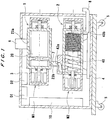
- FIG. 1 is a side view showing an evacuation apparatus according to the embodiment of the present invention.
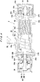
- FIG. 2 is a cross-sectional view showing a first vacuum pump shown in FIG. 1 .
- FIGS. 3A through 3D are schematic views illustrating the manner in which a gas is delivered.
- the evacuation apparatus comprises a first vacuum pump 1 serving as a booster pump, a second vacuum pump 2 serving as a main pump, and a housing (an enclosure) 3 for accommodating the first vacuum pump 1 and the second vacuum pump 2 therein.
- the housing 3 is fixed to an upper surface of a bottom plate 4, and the second vacuum pump 2 is installed on this bottom plate 4.
- Four wheels 5 (two of which are shown in FIG. 1 ) are fixed to a lower portion of the bottom plate 4, thus allowing the evacuation apparatus to be transportable.
- the first vacuum pump 1 is a Roots-type positive-displacement vacuum pump having a pair of Roots-type pump rotors 20 (only one of which is shown in FIG. 1 ), and the second vacuum pump 2 is a screw-type positive-displacement vacuum pump having a pair of screw-type pump rotors 40 (only one of which is shown in FIG. 1 ). That is, the pump rotors of the first vacuum pump 1 and the second vacuum pump 2 have different shapes from each other.
- the first vacuum pump 1 and the second vacuum pump 2 are disposed in parallel with each other in the housing 3, and the first vacuum pump 1 is disposed above the second vacuum pump 2.
- the first vacuum pump 1 has an inlet port 23a communicating with an inlet pipe 6, and the inlet pipe 6 is connected to a vacuum chamber (not shown in FIG. 1 ) incorporated in a substrate processing apparatus.
- the substrate processing apparatus include an etching apparatus and a CVD apparatus for respectively performing an etching process and a CVD process on a substrate such as a semiconductor wafer or a liquid crystal panel.
- An outlet port 23b is formed in a lower portion of the first vacuum pump 1, and this outlet port 23b is connected to an inlet port 43a of the second vacuum pump 2 via a connecting pipe 7.
- An outlet port 43b of the second vacuum pump 2 is connected to an outlet pipe 8, so that a gas (e.g., a process gas) is discharged to the exterior through the outlet pipe 8.
- a gas e.g., a process gas
- first vacuum pump 1 and the second vacuum pump 2 are connected in series and the second vacuum pump 2 is disposed downstream of the first vacuum pump 1.
- first vacuum pump 1 is disposed at a vacuum side (a vacuum-chamber side)
- second vacuum pump 2 is disposed at an atmospheric side.
- This second vacuum pump 2 is designed such that it can be started under an atmospheric pressure.
- the first vacuum pump 1 cannot be started by itself under the atmospheric pressure. Specifically, the first vacuum pump 1 is allowed to be started after an outlet-side pressure (i.e., a back pressure) of the first vacuum pump 1 is lowered to a certain degree.
- This first vacuum pump (i.e., the booster pump) 1 serves to increase a pumping speed of the second vacuum pump (i.e., the main pump) 2.
- the second vacuum pump (the main pump) 2 can be operated at pressures ranging from a vacuum to the atmospheric pressure, and serves to lower the outlet-side pressure (i.e., the back pressure) of the first vacuum pump 1.
- a pumping speed ratio of the first vacuum pump 1 to the second vacuum pump 2 is 50, 000 : 2, 500. If a degree of vacuum that is required for the vacuum chamber is higher than the ultimate pressure of the evacuation apparatus of the present embodiment, an ultra-high vacuum pump such as a turbo-molecular pump may be further disposed upstream of the first vacuum pump 1.
- a motor driver D1 for supplying electric current to a motor M1 of the first vacuum pump 1 and a motor driver D2 for supplying electric current to a motor M2 of the second vacuum pump 2 are installed on an upper portion of the housing 3.
- the rotational speeds of the motor M1 and the motor M2 are independently controlled by a control panel (a control unit) 10 via the motor drivers D1 and D2, respectively.
- the rotational speeds of the motor M1 and the motor M2 can be controlled by varying the frequency of the electric currents supplied respectively to the motor M1 and the motor M2.
- both the motor M1 and the motor M2 are a two-axes brushless DC motor.
- the first vacuum pump 1 comprises the pair of the multistage pump rotors 20 facing each other, and a rotor casing 23 in which the multistage pump rotors 20 are disposed.
- a small gap is formed between the pump rotors 20 and also between the pump rotors 20 and an inner surface of the rotor casing 23, so that these pump rotors 20 can be rotated in the rotor casing 23 in a non-contact manner.
- Each of the pump rotors 20 has a first-stage Roots rotor (an inlet-side rotor) 20a disposed at an inlet side, a second-stage Roots rotor (an outlet-side rotor) 20b disposed at an outlet side, and a rotating shaft 21 to which these Roots rotors 20a and 20b are fixed.
- An axial width W1 of the first-stage Roots rotor 20a is larger than an axial width W2 of the second-stage Roots rotor 20b.
- a ratio of the axial width W1 of the first-stage Roots rotor 20a to the axial width W2 of the second-stage Roots rotor 20b is 2 ⁇ 10 : 1, preferably 5 ⁇ 10 : 1.
- this ratio is 5 : 1.
- the axial width W1 of the first-stage Roots rotor 20a is two to ten times, preferably five to ten times the axial width W2 of the second-stage Roots rotor 20b.
- a pumping speed of the first-stage Roots rotor 20a is in the range of 20,000 to 100, 000 (l/min), preferably in the range of 50,000 to 100,000 (l/min). In this embodiment, the pumping speed of the first-stage Roots rotor 20a is 50,000 (l/min).
- the pumping speed of the second-stage Roots rotor 20b of this embodiment is 10,000 (l/min).
- Each of the rotating shafts 21 is rotatably supported by an inlet-side bearing 22A and an outlet-side bearing 22B.
- the inlet port 23a is formed in the rotor casing 23 and is located above the first-stage Roots rotor 20a.
- the outlet port 23b is also formed in the rotor casing 23 and is located below the second-stage Roots rotor 20b.
- the motor M1 which drives the first vacuum pump 1 comprises two motor rotors M1-1 fixed respectively to end portions of the rotating shafts 21, and motor stators M1-2 disposed radially outwardly of the motor rotors M1-1.
- the motor rotors M1-1 and the motor stators M1-2 are covered with a motor casing 24.
- FIG. 2 one of the two motor rotors Ml-1 and one of the two motor stators Ml-2 are illustrated.
- the motor stators M1-2 are connected to the above-mentioned motor driver D1.
- a cooling pipe 25B is embedded in a circumferential wall of the motor casing 24, so that the motor M1 is cooled by a cooling liquid flowing through the cooling pipe 25B.
- a pair of timing gears 28, which mesh with each other, are fixed to the other end portions of the rotating shafts 21. These timing gears 28 are housed in a gear casing 29.
- a cooling pipe 25A is embedded in a circumferential wall of the gear casing 29, so that the timing gears 28 and the bearings 22A are cooled by a cooling liquid flowing through the cooling pipe 25A. Since the synchronous rotation of the pump rotors 20 is performed by- the motor M1, the function of the timing gears 28 is to prevent the synchronous rotation of the pump rotors 20 from being disturbed due to accidental causes.
- Shaft sleeves 31A (one of which is shown in FIG. 2 ) are fixed respectively to the rotating shafts 21 at a position between the bearing 22A and the first-stage Roots rotor 20a.
- Labyrinth seals 32A (one of which is shown in FIG. 2 ) are disposed so as to surround outer surfaces of the shaft sleeves 31A, respectively.
- shaft sleeves 31B (one of which is shown in FIG. 2 ) are fixed respectively to the rotating shafts 21 at a position between the bearing 22B and the second-stage Roots rotor 20b, and labyrinth seals 32B (one of which is shown in FIG. 2 ) are disposed so as to surround outer surfaces of the shaft sleeves 31B, respectively.
- These labyrinth seals 32A and 32B prevent a gas (a process gas) compressed by the pump rotors 20 from entering regions where the bearings 22A, the bearings 22B, and the motor M1 are located. Oil is used as lubricant of the bearings 22A and 22B, so that even when by-products of the process gas are deposited on the bearings 22A and 22B, such by-products are removed by the oil flowing through the bearings 22A and 22B.
- the bearings 22A and the labyrinth seals 32A are covered with a bearing casing 33A, and the bearings 22B and the labyrinth seals 32B are covered with a bearing casing 33B.
- the rotor casing 23, the motor casing 24, and the bearing casings 33A and 33B are provided separately from each other, and the rotor casing 23, the bearing casings 33A and 33B, and the motor casing 24 are assembled in this order.
- supply ports 35A and 35B for supplying a clean gas are provided in the gear casing 29 and the bearing casing 33B, respectively.
- the clean gas supplied from the supply port 35A fills the interior space of the gear casing 29, and then flows through the bearings 22A and the labyrinth seals 32A in this order, thus preventing the bearings 22A and the labyrinth seals 32A from being exposed to the process gas.
- the clean gas supplied from the supply port 35B flows through the bearings 22B and the labyrinth seals 32B in this order, thus preventing the bearings 22B and the labyrinth seals 32B from being exposed to the process gas.
- the clean gas may comprise a stable gas, such as air or nitrogen (an inert gas), which does not react with the process gas.
- the first-stage Roots rotors 20a (and the second-stage Roots rotors 20b) are disposed so as to face each other in the rotor casing 23.
- the Roots rotors 20a i.e., the pump rotors 20
- a gas at inlet side is confined in a space defined by the Roots rotor 20a and the inner surface of the rotor casing 23, and then delivered to the outlet side.
- Such delivery of the gas is continuously performed, and hence the gas is evacuated from the vacuum chamber connected to the inlet port 23a (see FIG. 2 ).
- the Roots-type rotor is used in this embodiment, a screw-type or claw-type rotor may be used alternatively.
- the pump rotor is in the form of a multistage pump rotor having multistage rotors arranged in the axial direction.
- the number of stages of the pump rotor 20 is not limited to two.
- a pair of pump rotors each having three or more stages may be used.
- the load on the motor M1 can be small, and hence the power consumption of the motor M1 can be reduced. Further, it is possible to prevent the motor M1 from generating heat and thus to prevent the pump rotors 20 from being brought into contact with the inner surface of the rotor casing 23.
- FIG. 4 is a cross-sectional view showing the second vacuum pump shown in FIG. 1 .
- This second vacuum pump is different from the first vacuum pump in that pump rotors are of a screw-type.
- Other components of the second vacuum pump are the same as those of the first vacuum pump, and will not be described below repetitively.
- a pair of screw-type multistage pump rotors 40 are disposed in a rotor casing 43 so as to face each other. These pump rotors 40 are rotated synchronously in opposite directions by a motor M2 comprising motor rotors M2-1 and motor stators M2-2.
- Each of the pump rotors 40 has a first-stage screw rotor (inlet-side rotor) 40a, a second-stage screw rotor (outlet-side rotor) 40b, and a rotating shaft 41 to which these screw rotors 40a and 40b are fixed.
- the first-stage and second-stage screw rotors 40a and 40b are disposed so as to mesh with each other, respectively.
- the first-stage screw rotors 40a have a larger axial width and a larger pitch than those of the second-stage screw rotors 40b.
- Roots-type or claw-type rotors may be used alternatively.
- a small gap is formed between the pump rotors 40 and also between the pump rotors 40 and an inner surface of the rotor casing 43, so that these pump rotors 40 can be rotated in the rotor casing 43 in a non-contact manner.
- An inlet port 43a is formed in the rotor casing 43 and is located above the first-stage screw rotors 40a.
- An outlet port 43b is also formed in the rotor casing 43 and is located below the second-stage screw rotors 40b.
- the inlet port 43a is connected to the above-mentioned outlet port 23b (see FIGS. 1 and 2 ) of the first vacuum pump 1 via the connecting pipe 7.
- a gas e.g., a process gas
- a gas discharged from the first vacuum pump 1 is introduced into the rotor casing 43 from the inlet port 43a through the connecting pipe 7.
- the gas is compressed by the rotation of the first-stage screw rotors 40a and the second-stage screw rotors 40b, and is then discharged from the outlet port 43b.
- a largest pumping speed is achieved by the first-stage Roots rotors 20a, followed by the second-stage Roots rotors 20b, the first-stage screw rotors 40a, and the second-stage screw rotors 40b.
- the second vacuum pump 2 Since the second vacuum pump 2 is positioned closer to an atmospheric region than the first vacuum pump 1, an internal pressure of the second vacuum pump 2 is higher than that of the first vacuum pump 1. Accordingly, the by-products of the process gas are likely to be deposited in the second vacuum pump 2. In this embodiment, since the second vacuum pump 2 employs the screw-type pump rotors 40, the by-products deposited in the second vacuum pump 2 are scraped off by the rotation of the pump rotors 40.
- the screw rotors 40a and 40b are suitable for eliminating the by-products.
- the connecting pipe 7 has a pressure sensor 50 therein for measuring a pressure of a gas (e.g., a process gas) discharged from the first vacuum pump 1.
- the pressure sensor 50 is connected to the control panel 10 (see FIG. 1 ), so that the rotational speed -of the pump rotors 20 (see FIGS. 1 and 2 ) of the first vacuum pump 1 is controlled by the control panel 10 based on an output signal (i.e., a pressure of the gas) of the pressure sensor 50.
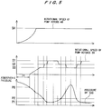
- FIG. 5 is a graph illustrating rotational speeds of the first vacuum pump and the second vacuum pump and a pressure of a gas measured by the pressure sensor.
- the second vacuum pump 2 is firstly started, and the rotational speed of the pump rotors 40 of the second vacuum pump 2 is increased until it reaches a rated rotational speed S4. Thereafter, the second vacuum pump 2 is operated so as to keep the rated rotational speed. After a predetermined period of time PT has passed from when the second vacuum pump 2 is started, the first vacuum pump 1 is started. As an alternative manner, the first vacuum pump 1 may be started after the pressure of the gas reaches a predetermine pressure P0 which is within an allowable range of an evacuating pressure of the second vacuum pump 2. After the rotational speed of the pump rotors 20 of the first vacuum pump 1 reaches S3, the pump rotors 20 are rotated at a constant rotational speed (S3).
- S3 constant rotational speed
- the pressure of the gas (the process gas) is further lowered.
- the rotational speed of the pump rotors 20 is further increased.
- the rotational speed of the pump rotors 20 reaches S2
- the pump rotors 20 are rotated so as to keep the rotational speed S2.
- the pressure of the gas reaches P1
- the rotational speed of the pump rotors 20 is further increased to reach a rated rotational speed S1.
- the pump rotors 20 are rotated at a constant rotational speed (S1). If the pressure of the gas is increased due to some sort of cause after the pump rotors 20 reach the rated rotational speed, then the pump rotors 20 is operated to decrease its rotational speed to S2 or S3.
- the rotational speed of the pump rotors 20 of the first vacuum pump 1 is changed according to the pressure of the gas delivered by the evacuation apparatus, whereby the load on the motor M1 can be reduced.
- the pressure sensor 50 is disposed in the connecting pipe 7 in this embodiment, the pressure sensor may be disposed in the rotor casing 43 of the second vacuum pump 2 at a position between the first-stage screw rotors 40a and the second-stage screw rotors 40b.
- the pressure sensor may be disposed in the inlet pipe 6 (see FIG. 1 ), the rotor casing 23 of the first vacuum pump 1, or the inlet port 23a.
- the rotational speed of the pump rotors 20 of the first vacuum pump 1 may be changed based on a temperature of the gas being delivered by the evacuation apparatus, a temperature of the rotor casing 23 of the first vacuum pump 1, or electric current flowing into the motor M1 of the first vacuum pump 1.
- a temperature sensor for measuring the temperature of the gas is disposed in the rotor casing 23 of the first vacuum pump 1, for example.
- a temperature sensor is disposed on an outer surface of the rotor casing 23.
- a current sensor for measuring the electric current flowing into the motor M1 is incorporated in the control panel 10.
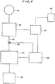
- FIG. 6 is a schematic view showing a substrate processing apparatus incorporating the evacuation apparatus according to the embodiment of the present invention.
- a process gas supply source 61 is disposed upstream of a vacuum chamber 60 so that a process gas is supplied from the process gas supply source 61 to the vacuum chamber 60.
- the vacuum chamber 60 is connected to the evacuation apparatus 63 according to the present embodiment via a pipe 62.
- This pipe 62 has a valve 64. By opening this valve 64, the vacuum chamber 60 and the evacuation apparatus 63 communicate with each other through the pipe 62.
- An exhaust gas cleaning apparatus 65 for treating an exhaust gas (i.e., the process gas) to be harmless is disposed downstream of the evacuation apparatus 63.
- the exhaust gas cleaning apparatus 65 include several types such as a dry type, a wet type, a combustion type, and a catalytic type.
- a first control unit 67 is connected to the vacuum chamber 60, so that process conditions under which a substrate is processed in the vacuum chamber 60 are controlled by the first control unit 67 (hereinafter, a process performed on the substrate in the vacuum chamber 60 will be referred to as a main process).
- the control conditions include a type and a temperature of the process gas supplied to the vacuum chamber 60, for example.
- a second control unit 68 is connected to the evacuation apparatus 63 and the valve 64, so that operating conditions of the evacuation apparatus 63 and open-close operation of the valve 64 are controlled by the second control unit 68.
- the operating conditions of the evacuation apparatus 63 include the rotational speeds of the pump rotors 20 and 40 (see FIG. 1 ) and timings of starting the first and second vacuum pumps 1 and 2, for example.
- the second control unit 68 is connected to the first control unit 67, so that the first control unit 67 sends the process conditions as a signal to the second control unit 68.
- the second control unit 68 controls the evacuating apparatus 63 and the valve 64 based on the signal (i.e., the process conditions) .
- a third control unit 66 for controlling a whole process is connected to the first control unit 67. This third control unit 66 sends the signal, which indicates the above-mentioned process conditions for the main process suitable for the whole process, to the first control unit 67.
- the first control unit 67 controls the main process based on this signal. Several kinds of results of the main process that has been performed in the vacuum chamber 60 are fed back to the first control unit 67.
- the valve 64 is closed and then the substrate is removed from the vacuum chamber 60. While the valve 64 is closed, the evacuation apparatus 63 can be operated at a lower rotational speed than the rated rotational speed, or the operation of the evacuation apparatus 63 can be stopped. Accordingly, a power consumption of the evacuation apparatus 63 can be reduced. In a case where the degree of vacuum developed in the vacuum chamber 60 is not required to be kept constant, the evacuation apparatus 63 may be operated at a lower rotational speed than the rated rotational speed while the valve 64 is opened.
- the present invention is applicable to an evacuation apparatus for evacuating a vacuum chamber of a substrate processing apparatus.
Landscapes
- Engineering & Computer Science (AREA)
- Mechanical Engineering (AREA)
- General Engineering & Computer Science (AREA)
- Chemical & Material Sciences (AREA)
- General Chemical & Material Sciences (AREA)
- Chemical Kinetics & Catalysis (AREA)
- Materials Engineering (AREA)
- Metallurgy (AREA)
- Organic Chemistry (AREA)
- Physics & Mathematics (AREA)
- Plasma & Fusion (AREA)
- Analytical Chemistry (AREA)
- Applications Or Details Of Rotary Compressors (AREA)
- Compressors, Vaccum Pumps And Other Relevant Systems (AREA)
- Control Of Positive-Displacement Pumps (AREA)
- Chemical Vapour Deposition (AREA)
Applications Claiming Priority (2)
| Application Number | Priority Date | Filing Date | Title |
|---|---|---|---|
| JP2003358424A JP4218756B2 (ja) | 2003-10-17 | 2003-10-17 | 真空排気装置 |
| PCT/JP2004/015563 WO2005038255A2 (en) | 2003-10-17 | 2004-10-14 | Evacuation apparatus |
Publications (2)
| Publication Number | Publication Date |
|---|---|
| EP1673539A2 EP1673539A2 (en) | 2006-06-28 |
| EP1673539B1 true EP1673539B1 (en) | 2019-07-31 |
Family
ID=34463300
Family Applications (1)
| Application Number | Title | Priority Date | Filing Date |
|---|---|---|---|
| EP04792713.2A Active EP1673539B1 (en) | 2003-10-17 | 2004-10-14 | Evacuation apparatus |
Country Status (5)
| Country | Link |
|---|---|
| US (2) | US9541088B2 (ja) |
| EP (1) | EP1673539B1 (ja) |
| JP (1) | JP4218756B2 (ja) |
| TW (1) | TWI326330B (ja) |
| WO (1) | WO2005038255A2 (ja) |
Families Citing this family (41)
| Publication number | Priority date | Publication date | Assignee | Title |
|---|---|---|---|---|
| EP1643129B1 (en) * | 2004-10-01 | 2008-05-14 | LOT Vacuum Co., Ltd. | Composite dry vacuum pump having roots rotor and screw rotor |
| GB0502149D0 (en) | 2005-02-02 | 2005-03-09 | Boc Group Inc | Method of operating a pumping system |
| GB0508872D0 (en) * | 2005-04-29 | 2005-06-08 | Boc Group Plc | Method of operating a pumping system |
| JP2006342688A (ja) * | 2005-06-07 | 2006-12-21 | Ebara Corp | 真空排気システム |
| FR2888894A1 (fr) * | 2005-07-20 | 2007-01-26 | Alcatel Sa | Pompage rapide d'enceinte avec economie d'energie |
| US8251678B2 (en) * | 2006-01-31 | 2012-08-28 | Ebara Corporation | Vacuum pump unit |
| WO2007095537A1 (en) * | 2006-02-13 | 2007-08-23 | Ingersoll-Rand Company | Multi-stage compression system and method of operating the same |
| JP4702236B2 (ja) * | 2006-09-12 | 2011-06-15 | 株式会社豊田自動織機 | 真空ポンプの運転停止制御方法及び運転停止制御装置 |
| JP2008088879A (ja) * | 2006-09-29 | 2008-04-17 | Anest Iwata Corp | 真空排気装置 |
| DE102006050943B4 (de) * | 2006-10-28 | 2020-04-16 | Pfeiffer Vacuum Gmbh | Vakuumpumpe und Verfahren zum Betrieb derselben |
| DE102010014884A1 (de) * | 2010-04-14 | 2011-10-20 | Baratti Engineering Gmbh | Vakuumpumpe |
| DE112011103800T5 (de) * | 2010-11-17 | 2013-09-05 | Ulvac, Inc. | Koppelstruktur für eine Unterdruckabsaugeinrichtung und Unterdruckabsauganordnung |
| BR112013014227B1 (pt) * | 2010-12-10 | 2021-03-16 | Ateliers Busch S.A. | bomba de vácuo para aplicações em máquinas de embalagem sobvácuo |
| TWI472678B (zh) | 2011-08-08 | 2015-02-11 | Inotera Memories Inc | 排氣裝置 |
| US10428807B2 (en) * | 2011-12-09 | 2019-10-01 | Applied Materials, Inc. | Pump power consumption enhancement |
| CN103321778A (zh) * | 2012-02-29 | 2013-09-25 | 伊顿公司 | 体积能量回收装置和系统 |
| JP6009193B2 (ja) * | 2012-03-30 | 2016-10-19 | 株式会社荏原製作所 | 真空排気装置 |
| JP5952616B2 (ja) * | 2012-03-30 | 2016-07-13 | 株式会社荏原製作所 | 真空ポンプ装置 |
| GB2501735B (en) * | 2012-05-02 | 2015-07-22 | Edwards Ltd | Method and apparatus for warming up a vacuum pump arrangement |
| GB2502134B (en) * | 2012-05-18 | 2015-09-09 | Edwards Ltd | Method and apparatus for adjusting operating parameters of a vacuum pump arrangement |
| JP2014001668A (ja) * | 2012-06-18 | 2014-01-09 | Toshiba Corp | ルーツポンプ |
| DE202012007108U1 (de) * | 2012-07-24 | 2012-08-22 | Ellcie Industries Gmbh | Vakuum-Vorrichtung |
| DE102012220442A1 (de) * | 2012-11-09 | 2014-05-15 | Oerlikon Leybold Vacuum Gmbh | Vakuumpumpensystem zur Evakuierung einer Kammer sowie Verfahren zur Steuerung eines Vakuumpumpensystems |
| JP6616611B2 (ja) * | 2015-07-23 | 2019-12-04 | エドワーズ株式会社 | 排気システム |
| US10316504B2 (en) * | 2015-08-05 | 2019-06-11 | Aqseptence Group, Inc. | Vacuum sewage system with monitoring system and method of use |
| DE102016102954A1 (de) | 2016-02-19 | 2017-08-24 | Multivac Sepp Haggenmüller Se & Co. Kg | Vakuumpumpe |
| FR3054005B1 (fr) * | 2016-07-13 | 2018-08-24 | Pfeiffer Vacuum | Procede de descente en pression dans un sas de chargement et de dechargement et groupe de pompage associe |
| DE202016005209U1 (de) * | 2016-08-30 | 2017-12-01 | Leybold Gmbh | Schraubenvakuumpumpe |
| DE102016216279A1 (de) | 2016-08-30 | 2018-03-01 | Leybold Gmbh | Vakuumpumpen-Schraubenrotor |
| DE202016005207U1 (de) * | 2016-08-30 | 2017-12-01 | Leybold Gmbh | Vakuumpumpen-Rotor |
| ES2709763T3 (es) * | 2016-10-28 | 2019-04-17 | Almig Kompressoren Gmbh | Compresor de aire de tornillo inyectado de aceite de dos etapas |
| JP2018178846A (ja) | 2017-04-12 | 2018-11-15 | 株式会社荏原製作所 | 真空ポンプ装置の運転制御装置、及び運転制御方法 |
| CN107084135A (zh) * | 2017-06-29 | 2017-08-22 | 德耐尔节能科技(上海)股份有限公司 | 一种干式螺旋真空泵 |
| CN111375325B (zh) * | 2018-12-31 | 2022-01-07 | 中国石油化工股份有限公司 | 一种联动式燃料油混合器、混油系统及混油方法 |
| US11815095B2 (en) * | 2019-01-10 | 2023-11-14 | Elival Co., Ltd | Power saving vacuuming pump system based on complete-bearing-sealing and dry-large-pressure-difference root vacuuming root pumps |
| FR3098869B1 (fr) * | 2019-07-17 | 2021-07-16 | Pfeiffer Vacuum | Groupe de pompage |
| US11668304B2 (en) * | 2020-02-27 | 2023-06-06 | Gardner Denver, Inc. | Low coefficient of expansion rotors for vacuum boosters |
| US11313368B2 (en) * | 2020-03-05 | 2022-04-26 | Elivac Company, Ltd. | Multistage pump assembly with at least one co-used shaft |
| US11939760B2 (en) | 2020-03-30 | 2024-03-26 | Aqseptence Group, Inc. | Vacuum sewage system with monitoring system and variable speed pump and methods of use |
| US11746782B2 (en) | 2020-04-03 | 2023-09-05 | Gardner Denver, Inc. | Low coefficient of expansion rotors for blowers |
| JP7427558B2 (ja) * | 2020-08-03 | 2024-02-05 | エドワーズ株式会社 | 真空排気系の洗浄装置 |
Citations (4)
| Publication number | Priority date | Publication date | Assignee | Title |
|---|---|---|---|---|
| JPH04272492A (ja) * | 1991-02-27 | 1992-09-29 | Ebara Corp | 多段メカニカルブースタポンプ |
| JP2000038999A (ja) * | 1998-05-20 | 2000-02-08 | Ebara Corp | 真空排気装置及び方法 |
| US6045343A (en) * | 1998-01-15 | 2000-04-04 | Sunny King Machinery Co., Ltd. | Internally cooling rotary compression equipment |
| US6375431B1 (en) * | 1999-11-17 | 2002-04-23 | Teijin Seiki Co., Ltd. | Evacuating apparatus |
Family Cites Families (30)
| Publication number | Priority date | Publication date | Assignee | Title |
|---|---|---|---|---|
| US3667874A (en) * | 1970-07-24 | 1972-06-06 | Cornell Aeronautical Labor Inc | Two-stage compressor having interengaging rotary members |
| US3922117A (en) * | 1972-11-10 | 1975-11-25 | Calspan Corp | Two-stage roots type compressor |
| FR2485201A1 (fr) * | 1980-06-20 | 1981-12-24 | Rech Geolog Miniere | Procede de mesure de grande precision des concentrations de gaz et produits volatils en situ et en continu et appareil in situ en oeuvre |
| DE3573152D1 (en) * | 1984-04-11 | 1989-10-26 | Hitachi Ltd | Screw type vacuum pump |
| JPS62243982A (ja) * | 1986-04-14 | 1987-10-24 | Hitachi Ltd | 2段型真空ポンプ装置およびその運転方法 |
| JPH0733834B2 (ja) * | 1986-12-18 | 1995-04-12 | 株式会社宇野澤組鐵工所 | ロータ内蔵ハウジングの外周温度が安定化された内部分流逆流冷却多段式の三葉式真空ポンプ |
| FR2621141B1 (fr) * | 1987-09-25 | 1989-12-01 | Cit Alcatel | Procede de demarrage de pompes a vide couplees en serie, et dispositif permettant la mise en oeuvre de ce procede |
| JPH01164287A (ja) * | 1987-12-18 | 1989-06-28 | Toshiba Corp | モータ駆動装置 |
| JP2567014B2 (ja) * | 1988-02-02 | 1996-12-25 | ファナック株式会社 | 液冷モータの冷却用管路接合構造 |
| US4850806A (en) * | 1988-05-24 | 1989-07-25 | The Boc Group, Inc. | Controlled by-pass for a booster pump |
| JPH0658278A (ja) * | 1992-08-05 | 1994-03-01 | Ebara Corp | 多段スクリュー式真空ポンプ |
| US5501583A (en) * | 1992-08-19 | 1996-03-26 | Hitachi, Ltd. | Turbo vacuum pump |
| EP0626516B1 (de) * | 1993-04-15 | 1997-06-04 | KNF Neuberger GmbH | Schmiermittelfreie Vakuum-Pumpeinrichtung |
| DE69625401T2 (de) * | 1995-03-20 | 2003-10-30 | Ebara Corp | Vakuumpumpe |
| EP0738833B1 (en) | 1995-04-19 | 2000-09-20 | Ebara Corporation | Multistage positive-displacement vacuum pump |
| JP3432679B2 (ja) * | 1996-06-03 | 2003-08-04 | 株式会社荏原製作所 | 容積式真空ポンプ |
| JP3767052B2 (ja) * | 1996-11-30 | 2006-04-19 | アイシン精機株式会社 | 多段式真空ポンプ |
| EP1077329A4 (en) * | 1999-03-05 | 2006-08-02 | Tokyo Electron Ltd | VACUUM MACHINE |
| GB0004404D0 (en) | 2000-02-24 | 2000-04-12 | Boc Group Plc | Improvements in vacuum pumps |
| GB0004239D0 (en) * | 2000-02-24 | 2000-04-12 | Crane John Uk Ltd | Seal assemblies |
| JP2002174174A (ja) | 2000-12-05 | 2002-06-21 | Teijin Seiki Co Ltd | 真空排気装置 |
| JP2002188589A (ja) | 2000-12-21 | 2002-07-05 | Canon Inc | 真空排気装置および真空排気方法 |
| JP3856661B2 (ja) * | 2001-06-06 | 2006-12-13 | 株式会社荏原製作所 | 真空ポンプ |
| CN100348865C (zh) | 2001-09-06 | 2007-11-14 | 爱发科股份有限公司 | 真空排气装置以及真空排气装置的运转方法 |
| DE10150015A1 (de) | 2001-10-11 | 2003-04-17 | Leybold Vakuum Gmbh | Mehrkammeranlage zur Behandlung von Gegenständen unter Vakuum, Verfahren zur Evakuierung dieser Anlage und Evakuierungssystem dafür |
| JP2003129979A (ja) * | 2001-10-23 | 2003-05-08 | Taiko Kikai Industries Co Ltd | 密閉式メカニカルブースタ |
| US6896764B2 (en) | 2001-11-28 | 2005-05-24 | Tokyo Electron Limited | Vacuum processing apparatus and control method thereof |
| US6739840B2 (en) * | 2002-05-22 | 2004-05-25 | Applied Materials Inc | Speed control of variable speed pump |
| JP2004100594A (ja) * | 2002-09-10 | 2004-04-02 | Toyota Industries Corp | 真空ポンプ装置 |
| US20050074353A1 (en) * | 2003-10-07 | 2005-04-07 | Delphi Technologies Inc. | Diaphragm-less vacuum booster |
-
2003
- 2003-10-17 JP JP2003358424A patent/JP4218756B2/ja not_active Expired - Lifetime
-
2004
- 2004-10-14 WO PCT/JP2004/015563 patent/WO2005038255A2/en active Application Filing
- 2004-10-14 US US10/563,255 patent/US9541088B2/en active Active
- 2004-10-14 EP EP04792713.2A patent/EP1673539B1/en active Active
- 2004-10-15 TW TW093131306A patent/TWI326330B/zh active
-
2010
- 2010-04-28 US US12/769,284 patent/US20100209259A1/en not_active Abandoned
Patent Citations (4)
| Publication number | Priority date | Publication date | Assignee | Title |
|---|---|---|---|---|
| JPH04272492A (ja) * | 1991-02-27 | 1992-09-29 | Ebara Corp | 多段メカニカルブースタポンプ |
| US6045343A (en) * | 1998-01-15 | 2000-04-04 | Sunny King Machinery Co., Ltd. | Internally cooling rotary compression equipment |
| JP2000038999A (ja) * | 1998-05-20 | 2000-02-08 | Ebara Corp | 真空排気装置及び方法 |
| US6375431B1 (en) * | 1999-11-17 | 2002-04-23 | Teijin Seiki Co., Ltd. | Evacuating apparatus |
Also Published As
| Publication number | Publication date |
|---|---|
| US20070104587A1 (en) | 2007-05-10 |
| JP4218756B2 (ja) | 2009-02-04 |
| TWI326330B (en) | 2010-06-21 |
| JP2005120955A (ja) | 2005-05-12 |
| WO2005038255A3 (en) | 2005-11-03 |
| WO2005038255A2 (en) | 2005-04-28 |
| TW200514919A (en) | 2005-05-01 |
| WO2005038255B1 (en) | 2005-12-29 |
| US9541088B2 (en) | 2017-01-10 |
| EP1673539A2 (en) | 2006-06-28 |
| US20100209259A1 (en) | 2010-08-19 |
Similar Documents
| Publication | Publication Date | Title |
|---|---|---|
| EP1673539B1 (en) | Evacuation apparatus | |
| KR101351667B1 (ko) | 진공 펌프 | |
| KR100843328B1 (ko) | 진공 배기 장치의 작동방법 | |
| US4797068A (en) | Vacuum evacuation system | |
| WO2003031821A1 (fr) | Pompe a vide a vis | |
| JP4180265B2 (ja) | 真空排気装置の運転方法 | |
| JP2003139055A (ja) | 真空排気装置 | |
| EP1609990B1 (en) | Vacuum device and vacuum pump | |
| WO2004083643A1 (en) | Positive-displacement vacuum pump | |
| JP2021510192A (ja) | ドライ真空ポンプ及び真空ポンプの同期電動機を制御する方法 | |
| US20080206072A1 (en) | Vacuum Apparatus | |
| JP2022526413A (ja) | ドライ真空ポンプおよびポンプ設備 | |
| JP2005171766A (ja) | ドライポンプ及びドライポンプの運転方法 | |
| GB2385890A (en) | A multi-stage vacuum pump with one end of a shaft able to move to allow for expansion | |
| US20070081893A1 (en) | Pump apparatus for semiconductor processing | |
| JPH0932766A (ja) | スクリュ−流体機械及びねじ歯車 | |
| JPH09317672A (ja) | 真空ポンプの改良 | |
| JP4111763B2 (ja) | 縦置きスクリュー式真空ポンプ | |
| TW202120792A (zh) | 泵單元 | |
| JP2004293377A (ja) | 多段式ドライポンプ | |
| JP2003322094A (ja) | 真空排気装置 | |
| JP2002174175A (ja) | 真空排気装置 |
Legal Events
| Date | Code | Title | Description |
|---|---|---|---|
| PUAI | Public reference made under article 153(3) epc to a published international application that has entered the european phase |
Free format text: ORIGINAL CODE: 0009012 |
|
| 17P | Request for examination filed |
Effective date: 20051230 |
|
| AK | Designated contracting states |
Kind code of ref document: A2 Designated state(s): DE FR GB |
|
| DAX | Request for extension of the european patent (deleted) | ||
| RBV | Designated contracting states (corrected) |
Designated state(s): DE FR GB |
|
| 17Q | First examination report despatched |
Effective date: 20090429 |
|
| GRAP | Despatch of communication of intention to grant a patent |
Free format text: ORIGINAL CODE: EPIDOSNIGR1 |
|
| RIC1 | Information provided on ipc code assigned before grant |
Ipc: H01J 37/32 20060101ALI20190131BHEP Ipc: F04C 23/02 20060101ALI20190131BHEP Ipc: F01C 21/00 20060101ALI20190131BHEP Ipc: C23C 16/44 20060101ALI20190131BHEP Ipc: F04C 18/02 20060101ALI20190131BHEP Ipc: F04C 18/00 20060101AFI20190131BHEP Ipc: F04C 25/02 20060101ALI20190131BHEP Ipc: F04C 18/12 20060101ALI20190131BHEP Ipc: F04C 18/16 20060101ALI20190131BHEP Ipc: F04C 28/08 20060101ALI20190131BHEP Ipc: F04C 23/00 20060101ALI20190131BHEP |
|
| INTG | Intention to grant announced |
Effective date: 20190221 |
|
| GRAS | Grant fee paid |
Free format text: ORIGINAL CODE: EPIDOSNIGR3 |
|
| GRAA | (expected) grant |
Free format text: ORIGINAL CODE: 0009210 |
|
| AK | Designated contracting states |
Kind code of ref document: B1 Designated state(s): DE FR GB |
|
| REG | Reference to a national code |
Ref country code: GB Ref legal event code: FG4D |
|
| REG | Reference to a national code |
Ref country code: DE Ref legal event code: R096 Ref document number: 602004054160 Country of ref document: DE |
|
| REG | Reference to a national code |
Ref country code: DE Ref legal event code: R097 Ref document number: 602004054160 Country of ref document: DE |
|
| PLBE | No opposition filed within time limit |
Free format text: ORIGINAL CODE: 0009261 |
|
| STAA | Information on the status of an ep patent application or granted ep patent |
Free format text: STATUS: NO OPPOSITION FILED WITHIN TIME LIMIT |
|
| 26N | No opposition filed |
Effective date: 20200603 |
|
| P01 | Opt-out of the competence of the unified patent court (upc) registered |
Effective date: 20230517 |
|
| PGFP | Annual fee paid to national office [announced via postgrant information from national office to epo] |
Ref country code: GB Payment date: 20230831 Year of fee payment: 20 |
|
| PGFP | Annual fee paid to national office [announced via postgrant information from national office to epo] |
Ref country code: FR Payment date: 20230911 Year of fee payment: 20 |
|
| PGFP | Annual fee paid to national office [announced via postgrant information from national office to epo] |
Ref country code: DE Payment date: 20230830 Year of fee payment: 20 |