EP1665402B1 - Thermoelektrische systeme mit grosser leistungsdichte - Google Patents
Thermoelektrische systeme mit grosser leistungsdichte Download PDFInfo
- Publication number
- EP1665402B1 EP1665402B1 EP04781451.2A EP04781451A EP1665402B1 EP 1665402 B1 EP1665402 B1 EP 1665402B1 EP 04781451 A EP04781451 A EP 04781451A EP 1665402 B1 EP1665402 B1 EP 1665402B1
- Authority
- EP
- European Patent Office
- Prior art keywords
- thermoelectric
- elements
- heat transfer
- transfer devices
- type
- Prior art date
- Legal status (The legal status is an assumption and is not a legal conclusion. Google has not performed a legal analysis and makes no representation as to the accuracy of the status listed.)
- Not-in-force
Links
Images


Classifications
-
- F—MECHANICAL ENGINEERING; LIGHTING; HEATING; WEAPONS; BLASTING
- F02—COMBUSTION ENGINES; HOT-GAS OR COMBUSTION-PRODUCT ENGINE PLANTS
- F02G—HOT GAS OR COMBUSTION-PRODUCT POSITIVE-DISPLACEMENT ENGINE PLANTS; USE OF WASTE HEAT OF COMBUSTION ENGINES; NOT OTHERWISE PROVIDED FOR
- F02G1/00—Hot gas positive-displacement engine plants
- F02G1/04—Hot gas positive-displacement engine plants of closed-cycle type
- F02G1/043—Hot gas positive-displacement engine plants of closed-cycle type the engine being operated by expansion and contraction of a mass of working gas which is heated and cooled in one of a plurality of constantly communicating expansible chambers, e.g. Stirling cycle type engines
-
- F—MECHANICAL ENGINEERING; LIGHTING; HEATING; WEAPONS; BLASTING
- F25—REFRIGERATION OR COOLING; COMBINED HEATING AND REFRIGERATION SYSTEMS; HEAT PUMP SYSTEMS; MANUFACTURE OR STORAGE OF ICE; LIQUEFACTION SOLIDIFICATION OF GASES
- F25B—REFRIGERATION MACHINES, PLANTS OR SYSTEMS; COMBINED HEATING AND REFRIGERATION SYSTEMS; HEAT PUMP SYSTEMS
- F25B21/00—Machines, plants or systems, using electric or magnetic effects
- F25B21/02—Machines, plants or systems, using electric or magnetic effects using Peltier effect; using Nernst-Ettinghausen effect
- F25B21/04—Machines, plants or systems, using electric or magnetic effects using Peltier effect; using Nernst-Ettinghausen effect reversible
-
- H—ELECTRICITY
- H10—SEMICONDUCTOR DEVICES; ELECTRIC SOLID-STATE DEVICES NOT OTHERWISE PROVIDED FOR
- H10N—ELECTRIC SOLID-STATE DEVICES NOT OTHERWISE PROVIDED FOR
- H10N10/00—Thermoelectric devices comprising a junction of dissimilar materials, i.e. devices exhibiting Seebeck or Peltier effects
-
- H—ELECTRICITY
- H10—SEMICONDUCTOR DEVICES; ELECTRIC SOLID-STATE DEVICES NOT OTHERWISE PROVIDED FOR
- H10N—ELECTRIC SOLID-STATE DEVICES NOT OTHERWISE PROVIDED FOR
- H10N10/00—Thermoelectric devices comprising a junction of dissimilar materials, i.e. devices exhibiting Seebeck or Peltier effects
- H10N10/10—Thermoelectric devices comprising a junction of dissimilar materials, i.e. devices exhibiting Seebeck or Peltier effects operating with only the Peltier or Seebeck effects
- H10N10/13—Thermoelectric devices comprising a junction of dissimilar materials, i.e. devices exhibiting Seebeck or Peltier effects operating with only the Peltier or Seebeck effects characterised by the heat-exchanging means at the junction
-
- H—ELECTRICITY
- H10—SEMICONDUCTOR DEVICES; ELECTRIC SOLID-STATE DEVICES NOT OTHERWISE PROVIDED FOR
- H10N—ELECTRIC SOLID-STATE DEVICES NOT OTHERWISE PROVIDED FOR
- H10N10/00—Thermoelectric devices comprising a junction of dissimilar materials, i.e. devices exhibiting Seebeck or Peltier effects
- H10N10/10—Thermoelectric devices comprising a junction of dissimilar materials, i.e. devices exhibiting Seebeck or Peltier effects operating with only the Peltier or Seebeck effects
- H10N10/17—Thermoelectric devices comprising a junction of dissimilar materials, i.e. devices exhibiting Seebeck or Peltier effects operating with only the Peltier or Seebeck effects characterised by the structure or configuration of the cell or thermocouple forming the device
-
- F—MECHANICAL ENGINEERING; LIGHTING; HEATING; WEAPONS; BLASTING
- F25—REFRIGERATION OR COOLING; COMBINED HEATING AND REFRIGERATION SYSTEMS; HEAT PUMP SYSTEMS; MANUFACTURE OR STORAGE OF ICE; LIQUEFACTION SOLIDIFICATION OF GASES
- F25B—REFRIGERATION MACHINES, PLANTS OR SYSTEMS; COMBINED HEATING AND REFRIGERATION SYSTEMS; HEAT PUMP SYSTEMS
- F25B2321/00—Details of machines, plants or systems, using electric or magnetic effects
- F25B2321/02—Details of machines, plants or systems, using electric or magnetic effects using Peltier effects; using Nernst-Ettinghausen effects
- F25B2321/021—Control thereof
-
- F—MECHANICAL ENGINEERING; LIGHTING; HEATING; WEAPONS; BLASTING
- F25—REFRIGERATION OR COOLING; COMBINED HEATING AND REFRIGERATION SYSTEMS; HEAT PUMP SYSTEMS; MANUFACTURE OR STORAGE OF ICE; LIQUEFACTION SOLIDIFICATION OF GASES
- F25B—REFRIGERATION MACHINES, PLANTS OR SYSTEMS; COMBINED HEATING AND REFRIGERATION SYSTEMS; HEAT PUMP SYSTEMS
- F25B33/00—Boilers; Analysers; Rectifiers
Definitions
- This disclosure relates to improved configurations for solid-state cooling, heating and power generation systems.
- thermoelectric devices utilize the properties of certain materials to develop a temperature gradient across the material in the presence of current flow.
- Conventional thermoelectric devices utilize P-type and N-type semiconductors as the thermoelectric material within the device. These are physically and electrically configured in such a manner that the desired function of heating or cooling is obtained.
- US 2003 / 005706 relates to a number of compact, high-efficiency thermoelectric system utilizing the advantages of thermal isolation in the direction of a working medium flow or movement, in manufacturable systems.
- thermoelectric devices today The most common configuration used in thermoelectric devices today is illustrated in Figure 1A .
- P-type and N-type thermoelectric elements 102 are arrayed in a rectangular assembly 100 between two substrates 104.
- a current, I passes through both element types.
- the elements are connected in series via copper shunts 106 saddled to the ends of the elements 102.
- a DC voltage 108 when applied, creates a temperature gradient across the TE elements.
- TEs are commonly used to cool liquids, gases and solid objects.
- Solid-state cooling, heating and power generation (SSCHP) systems have been in use since the 1960's for military and aerospace instrumentation, temperature control and power generation applications. Commercial usage has been limited because such systems have been too costly for the function performed, and have low power density so SSCHP systems are larger, more costly, less efficient and heavier than has been commercially acceptable.
- Equation (3) The term on the right side of Equation (3) in brackets is independent of the size (or dimensions) of the TE system, and so the amount of cooling q OPT is only a function of material properties and K .
- thermoelectric systems it is advantageous to make a device smaller for the same cooling output.
- FIG. 1C depicts a typical TE couple. While several parasitic losses occur, one of the largest for a well-designed TE is that from shunt 106.
- the resistance of shunt 106 per TE element 102 is approximately, R PC ⁇ B C + G C W C ⁇ T C ⁇ P SC
- G C is the gap between the TE elements.
- B C is the TE element and shunt breadth.
- W C is the TE element and shunt width.
- T C is the shunt thickness.
- P SC is the shunt resistivity.
- this disclosure describes a new family of SSCHP configurations. These configurations achieve compact, high-efficiency energy conversion and can be relatively low cost.
- TE elements or modules are sandwiched between heat exchangers.
- the TE elements are advantageously oriented such that for any two elements sandwiching a heat exchanger, the same temperature type side faces the heat exchanger.
- the cooler side of each of the TE elements sandwiching a heat exchanger face the same heat exchanger or shunt, and thus each other.
- at least one working medium is passed sequentially through at least two heat exchangers so that the cooling or heating provided is additive on the working medium.
- a TE device achieves increased or improved efficiency by subdividing the overall assembly of TE elements into thermally isolated subassemblies or sections.
- the heat exchangers may be subdivided so as to provide thermal isolation in the direction of working medium flow.
- a TE system has a plurality of TE elements forming a TE array with a cooling side and a heating side, wherein the plurality of TE elements are substantially isolated from each other in at least one direction across the array.
- the thermal isolation is in the direction of the working media flow.
- This thermal isolation can be provided by having a heat exchanger configured in sections such that the heat exchanger has portions which are thermally isolated in the direction of working fluid flow.
- heat exchangers of the same temperature type for the working fluid provides a type of thermal isolation in itself.
- the heat exchangers or the TE elements, or TE modules or any combination may be configured to provide thermal isolation in the direction of the working fluid flow over and above the thermal isolation provided by having a series or sequence of heat exchangers through which at least one working fluid passes in sequence.
- cooling and/or heating applications are equally applicable to power generation applications, and any configuration, design detail, and analogous part that may be combined in any way to produce an assembly for power generation, is also applicable.
- the system may be tuned in a manner to maximize the efficiency for the given application, but the general principles apply.
- thermoelectric system having a plurality of N-type thermoelectric elements and a plurality of P-type thermoelectric elements.
- a plurality of first shunts and a plurality of second shunt are provided. At least some of the first shunts are sandwiched between at least one N-type thermoelectric element and at least one P-type thermoelectric element, and at least some of the second shunts sandwiched between at least one P-Type thermoelectric element and at least one N-Type thermoelectric elements, so as to form a stack of thermoelectric elements, with alternating first and second shunts, wherein at least some of the first shunts and at least some of the second shunts project away from the stack in differing directions.
- thermoelectric elements are constructed to be quite thin, such as from 5 microns, to 1.2 mm, from 20 microns to 200 microns for superlattice and hetrostructure thermoelectric designs, and in another embodiment from 100 to 600 microns. These designs provide for significant reduction in the usage of thermoelectric material.
- thermoelectric system further comprises a current source electrically coupled to the stack, the drive current traversing through the heat transfer devices and thermoelectric elements in series.
- the heat transfer devices thermally isolate at least some of the P-type thermoelectric elements from at least some of the N-type thermoelectric elements.
- the heat transfer devices accept a working fluid to flow through them in a defined direction.
- the heat transfer devices are heat exchangers and may have a housing with one or more heat exchanger elements inside.
- At least some of the first shunts are constructed of a first electrode portion electrically isolated from and thermally coupled to a second shunt portion.
- thermoelectric module and TE module are used in the broad sense of their ordinary and accustomed meaning, which is (1) conventional thermoelectric modules, such as those produced by Hi Z Technologies, Inc. of San Diego, California, (2) quantum tunneling converters, (3) thermionic modules, (4) magneto caloric modules, (5) elements utilizing one, or any combination of thermoelectric, magneto caloric, quantum, tunneling and thermionic effects, (6) any combination, array, assembly and other structure of (1) through (6) above.
- thermoelectric element is more specific to indicate an individual element that operates using thermoelectric, thermionic, quantum, tunneling, and any combination of these effects.
- thermoelectric or SSCHP systems are described by way of example. Nevertheless, it is intended that such technology and descriptions encompass all SSCHP systems.
- thermoelectric element or array or module may be at ambient temperature with the "cold,” side at a cooler temperature than the ambient. The converse may also be true. Thus, the terms are relative to each other to indicate that one side of the thermoelectric is at a higher or lower temperature than the counter-designated temperature side.
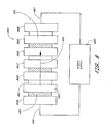
- Figure 2 illustrates a first generalized embodiment of an advantageous arrangement for a thermoelectric array 200.
- the array 200 has a plurality of TE modules 201, 211, 212, 213, 218 in good thermal communication with a plurality of first side heat exchangers 202, 203, 205 and a plurality of second side heat exchangers 206, 207 209.
- the designation first side heat exchanger and second side heat exchanger does not implicate or suggest that the heat exchangers are on one side or the other side of the entire SSCHP system, but merely that they are in thermal communication with either the colder side or the hotter side of the thermoelectric modules. This is apparent from the figure in that the heat exchangers are actually sandwiched between thermoelectric modules.
- thermoelectric modules In that sense, they are in thermal communication with a first side or a second side of the thermoelectric modules.
- the colder side of a first TE module 201 is in thermal contact with a first side heat exchanger 205 and the hot side of the TE module 201 is in thermal contact with an inlet second side heat exchanger 206.
- a second working media 215, such as a fluid enters the array 200 in the upper right hand corner of Figure 2 through the inlet second side heat exchange 206, and exits near the lower left from a final or outlet second side heat exchanger 209.
- a first working media 216 enters at the upper left through an inlet first side heat exchanger 202 and exits near the lower right from a final or outlet first side heat exchanger 205.
- First conduits 208 convey the second working media 215 and second conduits 204 convey the first working media 216 sequentially through various heat exchangers 202, 203, 205, 206, 207 and 209 as depicted.
- the second working media 215 absorbs heat from the TE module 201 as it passes downward through the inlet second side heat exchanger 206.
- the second working media 215 passes through conduit 208 and upwards into and through the second side heat exchanger 207.
- In good thermal communication with the heat exchanger 207 are the hotter sides of the TE modules 211 and 212, which have been configured so that their respective hotter sides face toward one another to sandwich the second side heat exchanger 207.
- the second side working media 215, is further heated as it passes through the second side heat exchanger 207.
- the second side working media 215 next passes through the second side heat exchanger 209, where again, the hotter sides of the TE modules 213 and 218 sandwich and transfer heat to the second side heat exchanger 209, further heating the second side working media 215. From the heat exchanger 209, the second working media 215 exits the array 200 from the outlet or final second side heat exchange 209.
- the first working media 216 enters the inlet first side heat exchanger 202 at the upper left corner of Figure 2 .
- This heat exchanger 202 is in good thermal communication with the colder side of the TE module 218.
- the first working media 216 is cooled as it passes through the inlet first side heat exchanger 202, on through another first side exchanger 203 and finally through the outlet first side heat exchanger 205, where it exits as colder working media 217.
- thermoelectric cooling and heating is provided by electrical power through wiring 210 into TE module 218, and similarly into all the other TE modules.
- working media is placed in good thermal contact with the cold side of the TE module at the left hand side of the array, so that heat is extracted from the media.
- the media then contacts a second and third TE module where additional heat is extracted, further cooling the media.
- the process of incremental cooling continues, as the media progresses to the right through the desired number of stages.
- the media exits at the right, after being cooled the appropriate amount.
- a second media enters the system at the far right and is incrementally heated as it passes through the first stage. It then enters the next stage where it is further heated, and so on.
- the heat input at a stage is the resultant of the heat extracted from the adjacent TE modules' cold sides, and the electrical power into those modules.
- the hot side media is progressively heated as it moves in a general right to left direction.
- the system provides benefit if both media enter at the same temperature and progressively get hotter and colder.
- the media can be removed from or added to the cool or hot side at any location within the array.
- the arrays can be of any useful number of segments such as 5, 7, 35, 64 and larger numbers of segments.
- the system can also be operated by reversing the process with hot and cold media in contact with TE modules, and with the hot and cold media moving from opposite ends (as in Figure 2 but with the hot media entering as media 216 and the cold media entering as media 215).
- the temperature gradient so induced across the TE modules produces an electric current and voltage, thus converting thermal power to electrical power. All of these modes of operation and those described in the text that follows are part of the inventions.
- the progressive heating and cooling of media in a counter flow configuration as described in Figure 2 can produce higher thermodynamic efficiency than under the same conditions in a single TE module without the benefit of the thermal isolation.
- the configuration shown in Figure 2 thus presents an SSCHP system 200 that obtains thermal isolation through the segments or stages of heat exchangers sandwiched between thermoelectric modules in a compact easily producible design.
- thermoelectric modules themselves may be constructed to provide thermal isolation in the direction of media flow and each heat exchanger or some of the heat exchangers may be configured to provide thermal isolation in a individual heat exchanger through a configuration as will be described further in Figure 5 or other appropriate configurations.
- the heat exchanger could be segmented in the direction of flow to provide increased thermal isolation along the flow of a single TE module such as the TE module 218 and the inlet heat exchanger 202.
- Figure 3 depicts an array 300 of the same general design as in Figure 2 , consisting of a plurality of TE modules 301 and colder side heat exchangers 302, 305, and 307 connected so that a first working medium 315 follows the sequential heat exchanger to heat exchanger path shown. Similarly, a plurality of hot side heat exchangers 309, 311 and 313 convey a hotter side working medium 317 in a sequential or staged manner in the direction shown by the arrows.
- the TE modules 301 are arranged and electrically powered as in the description of Figure 2 .
- the lower half of Figure 3 depicts the cold side temperatures or temperature changes 303, 304, 306, 308 of the colder side working medium and hot side temperatures 310, 312, 314 of the hotter side working medium.
- the colder side working medium 315 enters and passes through an inlet colder side heat exchanger 302.
- the working medium's temperature drop 303 in passing through the inlet colder side heat exchanger 302 is indicated by the drop 303 in the cold side temperature curve Tc.
- the colder side working medium 315 is further cooled as it passes through the next stage colder side heat exchanger 305, as indicated by a temperature drop 304 and again as it passes through a third colder side heat exchanger 307, with an accompanying temperature drop 306.
- the colder side working medium 315 exits as colder fluids 316 at temperature 308.
- the hotter side working medium 317 enters a first or inlet hotter side heat exchanger 309 and exits at a first temperature 310 as indicated by the hotter side temperature curve T H in the Figure 3 .
- the hotter side working medium progresses through the array 300 in stages as noted in Figure 2 , getting progressively hotter, finally exiting after passing through outlet hotter side heat exchanger 313 as hotter working fluid at 318 and at a hotter temperature 314. It is readily seen that by increasing the number of stages (that is TE modules and heat exchangers) the amount of cooling and heating power can be increased, the temperature change produced by each heat exchanger can be reduced, and/or the amount of media passing through the array increased. As taught in the U.S. Patent No. 6,539,725 , efficiency also can increase with more stages, albeit at a diminishing rate.
- Figure 4A depicts an array 400 with three TE modules 402, four heat exchangers 403 and two conduits 405 configured as described in Figures 2 and 3 .
- Colder and hotter side working fluids enters at a colder side inlet 404 and a hotter side inlet 407, respectively and exit respectively at a colder side exit 406 and a hotter side exit 408.
- Figure 4B is a more detailed view of one embodiment of a heat exchanger 403. It is shown as a type suitable for fluid media.
- the heat exchanger assembly 403, has consists of an outer housing 412 with an inlet 410 and an exit 411, heat exchanger fins 414, and fluid distribution manifolds 413.
- the operation of array 400 is essentially the same as described in Figures 2 and 3 .
- the number of the TE modules 402 is three in Figure 4 , but could be any number.
- the housing 412 is thermally conductive, being made from a suitable material such as corrosion protected copper or aluminum.
- heat exchanger fins 414 advantageously are folded copper, or aluminum soldered or braised to the housing 412, so as to achieve good thermal conductivity across the interface to the TE Module.
- the Fins 414 can be of any form, but preferably of a design well suited to achieve the heat transfer properties desired for the system. Detailed design guidelines can be found in " Compact Heat Exchangers", Third Edition by W. M. Kays and A. L. London .
- any other suitable heat exchangers can be used, such as perforated fins, parallel plates, louvered fins, wire mesh and the like.
- perforated fins such as perforated fins, parallel plates, louvered fins, wire mesh and the like.
- Such configurations are known to the art, and can be used in any of the configurations in any of Figures 2 through 11 .
- Figure 5A depicts an alternative configuration to that of Figure 4 for the conduit connections to provide flow from heat exchanger stage to heat exchanger.
- the array 500 has first and second TE modules 501 and 510, three heat exchangers 502, 503 and 506, and a conduit 504.
- first and second TE modules 501 and 510 three heat exchangers 502, 503 and 506, and a conduit 504.
- the particular number of two first side heat exchangers 502, 503 and one second side heat exchanger 506 is not restrictive and other numbers could be provided.
- FIG. 5B illustrates an enlarged view of a preferred embodiment for the heat exchangers 502, 503, 506.
- This heat exchanger configuration as shown in Figure 5B would be appropriate for the other embodiments and can be used in any of the configuration in Figures 2-8 and Figure 11 .
- This advantageous embodiment for one or more of the heat exchangers in such configurations has an outer housing 516 with segmented heat exchanger fins 511 separated by gaps 513.
- Working fluid enters through an inlet 505 and exits through exit 508.
- the heat exchanger could be made so that it is anisotropic such that it is thermally conductive for a section and non-thermally conductive for another section rather than having actual physical gaps between heat exchanger fins.
- thermal isolation to be obtained between stages of an individual heat exchanger segment and another individual heat exchanger segment in the direction of flow. This would be thermal isolation provided in addition to the thermal isolation provided by having stages of heat exchangers in the embodiments described in Figures 2-5 .
- a first working fluid 507 which, for example is to be heated, enters an inlet 505 and passes downward through an inlet or first heat exchanger 502 in thermal communication with a first TE module 501.
- the working fluid 507 exits at the bottom and is conducted to subsequent heat exchanger 503 through conduit 504, where it again passes in a downward direction past a second TE module 510 and exits through as a hotter working 508.
- a second working fluid 517 enters from the bottom of Figure 5A through inlet 518 and travels upward through a third heat exchanger 506 past the colder sides (in the present example) of TE modules 501 and 510.
- the heat exchanger 506 is in good thermal communication with the colder sides of the TE modules 501 and 510.
- the working fluids 507 and 517 form a counter flow system in accordance with the teaching of U.S. Patent No. 6,539,725 referenced above.
- the heat exchangers 502, 503 and 506, shown in detail in Figure 5B are constructed to have high thermal conductivity from the faces of the TE modules 501, 510, 510, through the housing 516 and to the heat exchanger fins 511 (depicted in four isolated segments).
- Figure 6 depicts yet another heater/cooler system 600 that is designed to operate beneficially with working gases.
- the heater/cooler 600 has TE modules 601, 602 in good thermal communication with first side heat exchangers 603, 605 and second side heat exchangers 604.
- a first working fluid, such as air or other gases 606, is contained by ducts 607, 708, 610 and a second working fluid 616 is contained by ducts 615, 613.
- Fans or pumps 609, 614 are mounted within ducts 608, 615.
- the first working fluid 606 enters the system 600 through an inlet duct 607.
- the working fluid 606 passes through a first heat exchanger 603 where, for example, it is heated (or cooled).
- the working fluid 606 then passes through the fan 609 which acts to pump the working fluid 606 through the duct 608, and through the second heat exchanger 605, where it is further heated (or cooled), and out an exit duct 610.
- a working fluid such as air or another gas, enters through an inlet duct 615. It is pushed by a second fan or pump 614 through a third heat exchanger 604 where, in this example, it is cooled (or heated).
- the cooled (or heated) working fluid 616 exits through an exit duct 613.
- the system 600 can have multiple segments consisting of additional TE modules and heat exchangers and isolated, segmented heat exchangers as described in Figure 5B . It can also have multiple fans or pumps to provide additional pumping force.
- one duct for example 607, 608, can have one fluid and the other duct 613, 615 a second type of gas. Alternately, one side may have a liquid working fluid and the other a gas. Thus, the system is not restricted to whether a working medium is a fluid or a liquid.
- the exit duct 613 could be routed around the fan duct 609.
- Figure 7A depicts a heating and cooling system 700 for beneficial use with a fluid.
- the assembly has a plurality of TE modules 701 with a plurality of first side working media 703 and a plurality of second side working media 704.
- both the first side working media 703 and the second side working media 704 form disks.
- the first side working media 703 are attached to a first side shaft 709, and the second side working media 704 are attached to a second side shaft 708.
- the shafts 708, 709 are in turn attached to first side motor 706 and second side motor 705, respectively, and to corresponding bearings 707.
- the preferred direction of motor rotation is indicated by arrows 710 and 711.
- a separator 717 both divides the array into two portions and positions the TE modules 701.
- the TE modules 701, held in position by the separator 717, are spaced so as to alternately sandwich a first side working medium 703 and a second side working medium 704.
- the modules are oriented such that their cold sides and hot sides face each other as in the previous embodiments.
- the working media 703, 704 are in good thermal communication with the TE elements 701.
- Thermal grease or the like is advantageously provided at the interface between the thermoelectric element 701 and the working media 703, 704. The purpose of the grease becomes apparent in the discussion below regarding the operation of the working media 703, 704.
- a first side housing section 714 and second side housing section 715 contain fluid conditioned by the system 700. Electrical wires 712, 713 connect to the TE modules 701 to provide drive current for the TE modules.
- Figure 7B is a cross sectional view 7B-7B through a portion of the system 700 of Figure 7A .
- a first fluid 721 and a second fluid 723 are represented along with their direction of flow by arrows 721 and 723.
- the first fluid exits as represented by the arrow 722 and a second exits as represented by the arrow 724.
- the system 700 operates by passing current through electrical wires 712 and 713 to TE modules 701.
- the TE modules 701 have their cold and hot sides facing each other, arranged in the fashion as described in Figures 2 and 3 . For example, their adjacent cold sides both face the first side working media 703 and their hot sides face the second side working media 704.
- the Separator 717 serves the dual function of positioning the TE modules 701 and separating the hot side from the cooled side of the array 700.
- a second fluid 723 is to be cooled.
- the cooling occurs by thermal exchange with second side media 704.
- the second side media 704 rotate, the portion of their surface in contact with the colder side of the TE modules 701 at any given time is cooled.
- the second media 704 cool the second side fluid that then exits at exit 724.
- the second fluid is confined within the array 700 by the housing section 715 and the separator 717.
- first fluid 721 is heated by the first side media 703 in thermal contact with the hotter side of the TE modules 701. Rotation (indicated by arrow 711) moves the heated portion of first media 703 to where the first fluid 721 can pass through them and be heated via thermal contact.
- the first fluid 721 is contained between the housing 714 and the separator 717 and exits at exit 722.
- thermally conductive grease or liquid metal such as mercury can be used to provide good thermal contact between the TE modules 701 and the media 703, 704 at the region of contact.
- Figure 7A and 7B may also be advantageously used to cool or heat external components such as microprocessors, laser diodes and the like.
- the disks would contact the part using the thermal grease or liquid metal or the like to transfer the heat to or from the part.
- Figure 7C depicts a modified version of the system 700 in which the TE modules 701 are segmented to achieve thermal isolation.
- Figure 7C shows a detailed view of the portion of array 700 in which TE modules 701 and 702 transfer thermal power to heat moving media 704 and 703 (the rotating discs in this example).
- the moving media 704 and 703 rotate about axes 733 and 734, respectively.
- the working media 704 and 703 rotate in opposite directions as indicated by arrows 710 and 711.
- moving media 704, 703 rotate, heat transfer from different sections of TE modules 701 and 702 come into thermal contact with them and incrementally change the temperature of the moving media 704, 703.
- a first TE module 726 heats moving medium 704 at a particular location.
- the material of the moving media 704 at that location moves into contact with a second TE module 725 as moving medium 704 rotates counter clockwise.
- the same portion of moving medium 704 then moves on to additional TE module segments 701.
- the opposite action occurs as moving medium 703 rotates counterclockwise and engages TE modules 701 and then subsequently TE modules 725 and 726.
- moving media 704, 703 have good thermal conductivity in the radial and axial directions, and poor thermal conductivity in their angular direction, that is, the direction of motion. With this characteristic, the heat transfer from one TE module 725 to another TE module 726 by conductivity through the moving media 704 and 708 is minimized, thereby achieving effective thermal isolation.
- TE elements 701 are very thin compared to their length in the direction of motion of moving media 704, 703, and have relatively poor thermal conductivity in that direction, they will exhibit effective thermal isolation over their length. They will conduct heat and thus respond thermally as if they were constructed of separate TE modules 701. This characteristic in combination with low thermal conductivity in the direction of motion within the moving media 704, 703 can achieve effective thermal isolation and thereby provides performance enhancements.
- Figure 7D depicts an alternative configuration for moving media 704, 703 in which the media are constructed in the shape of wheels 729 and 732 with spokes 727 and 731. In the spaces between spokes 727 and 731 and in good thermal contact with them, are heat exchanger material 728 and 730.
- the system 700 can operate in yet another mode that is depicted in Figure 7D .
- working fluid (not shown) moves axially along the axes of the array 700 passing through moving media 704, 703 sequentially from one medium 704 to the next moving medium 704, and so on in an axial direction until it passes through the last medium 704 and exits.
- a separate working fluid passes through individual moving medium 703 axially through array 700.
- the ducts 714 and 715 and separator 717 are shaped to form a continuous ring surrounding moving media 704, 703 and separating medium 704 from medium 703.
- the hot side working fluid passes through heat exchanger 728, moves through the array 700 in the opposite direction of the working fluid moving through heat exchanger 730.
- the array 700 acts as a counterflow heat exchanger, and a succession of sequential heat exchangers 728 and 730 incrementally heat and cool the respective working fluids that pass through them.
- the thermally active components can be TE modules 701 that can be constructed so as to have effective thermal isolation in the direction of motion of the moving media 704, 703.
- the TE modules 701 and 702 can be segments as described in Figure 7C . In the latter case, it is further advantageous for the thermal conductivity of the moving media 704, 703 to be low in the direction of motion so as to thermally isolate portions of the outer discs 729 and 732 of the moving media 704, 703.
- the design could be further contain radial slots (not shown) in the sections 729 and 732 that are subject to heat transfer from TE modules 701 and 702 to achieve thermal isolation in the direction of motion.
- Figure 8 depicts another embodiment of a thermoelectric system an 800 having a plurality of TE elements 801 (hatched) and 802 (unhatched) between first side heat exchangers 803 and second side heat exchangers 808.
- a power supply 805 provides current 804 and is connected to heat exchangers 808 via wires 806, 807.
- the system 800 has conduits and pumps or fans (not shown) to move hot and cold side working media through the array 800 as described, for example, in Figures 2 , 3 , 4 , 5 , 6 and 7 .
- TE modules (having many TE elements) are replaced by TE elements 801 and 802.
- hatched TE elements 801 may be N-type TE elements and unhatched TE elements 802 may be P-type TE elements.
- heat exchangers 803 and 808 it is advantageous to configure heat exchangers 803 and 808 so that they have very high electrical conductivity.
- the housing of the heat exchangers 803, 808 and their internal fins or other types of heat exchanger members can be made of copper or other highly thermal and electrical conductive material.
- the heat exchangers 803 and 808 can be in very good thermal communication with the TE elements 801 and 802, but electrically isolated.
- electrical shunts can be connected to the faces of TE elements 801 and 802 to electrically connect them in a fashion similar to that shown in Figure 1 , but with the shunts looped past heat exchangers 803 and 808.
- DC current 804 passing from N-type 801 to P-type TE elements 802 will, for example, cool the first side heat exchanger 803 sandwiched between them, and current 804 passing from P-type TE elements 802 to N-type TE elements 801 will then heat the second side heat exchanger 808 sandwiched between them.
- the Array 800 can exhibit minimal size and thermal losses since the shunts, substrates and multiple electric connector wires of standard TE modules can be eliminated or reduced. Further, TE elements 801 and 802 can be heterostructures that accommodate high currents if the components are designed to have high electrical conductivity and capacity. In such a configuration, the array 800 can produce high thermal power densities.
- Figure 9 depicts a thermoelectric system 900 of the same general type as described in Figure 8 , with P-type TE elements 901 and N-type TE elements 902 between, and in good thermal contact with first side heat transfer members 903 and second side heat transfer members 905.
- the heat transfer members 903 and 905 have the form of thermally conductive rods or heat pipes. Attached to, and in good thennal communication with the heat transfer members 903 and 905 are heat exchanger fins 904, 906, or the like.
- a first conduit 907 confines the flow of a first working medium 908 and 909 and a second conduit 914 confines the flow of a second working fluid 910 and 911.
- Electrical connectors 912 and 913 conduct current to the stack of alternating P-type and N-type TE elements 901, 902, as described in Figure 8 .
- first conduit 907 surrounds and confines a first working media 908 so it exits at a changed temperature as working fluid 909. Portions of the first conduit 907 thermally insulate the TE elements 901 and 902 and the second side heat transfer members 905 from the first (hot in this case) working media 908 and 909.
- the second working media 910 enters through the second conduit 914, is cooled (in this example) as it passes through the second side heat exchangers 906 and exits as cooled fluid 911.
- the TE elements 901, 902 provide cooling to the second side heat transfer members 905 and hence, to heat exchanger fins 906.
- the second side conduit 914 acts to confine the second (cooled in this example) working media 910, and to insulate it from other parts of array 900.
- TE modules may be substituted for the TE elements 901, 902.
- the heat exchangers 904, 906 can be of any design that is advantageous to the function of the system.
- the configurations of Figures 8 and 9 provide a relatively easily manufacturable system that also provides enhanced efficiency from thermal isolation.
- the heat exchangers 808, 803 which alternate between P-type and N-type thermal electric elements, will either be of the colder or hotter heat exchanger type, but will be reasonably thermally isolated from each other and cause the thermoelectric elements of the P and N type to be reasonably thermally isolated from one another.
- FIG. 10 depicts another thermoelectric array system (1000) that provides thermal isolation.
- this configuration may perform the function of a system that utilizes cooling and heating of the same medium to dehumidify, or remove precipitates, mist, condensable vapors, reaction products and the like and return the medium to somewhat above its original temperature.
- the system 1000 consists of a stack of alternating P-type TE elements 1001 and N-type TE elements 1002 with interspersed cold side heat transfer elements 1003 and hot side heat transfer elements 1004.
- heat exchanger fins 1005, 1006 are provided for both the colder side heat transfer elements 1003 and the hotter side heat transfer elements 1004.
- a colder side conduit 1018 and a hotter side conduit 1019 direct working fluid 1007, 1008 and 1009 within the array 1000.
- a fan 1010 pulls the working fluid 1007, 1008 and 1009 through the array 1000.
- colder side insulation 1012 thermally isolates the working fluid 1007 while travelling through the colder side from the TE element stack and hotter side insulation 1020 preferably isolates the working fluid while travelling through the hotter side from the TE element stack.
- a baffle 1010 or the like separates the colder and hotter sides.
- the baffle 1010 has passages 1010 for working fluids 1021 to pass through.
- fluid passages 1017 allow fluid 1016 to enter the hot side flow passage.
- a screen 1011 or other porous working fluid flow restrictor separates the colder from the hotter side of array 1000. Condensate, solid precipitate, liquids and the like 1013 accumulate at the bottom of the array 1000, and can pass through a valve 1014 and out a spout 1015.
- some of the working fluid 1021 can be passed from the colder to the hotter side through bypass passages 1020.
- the flow restrictor 1011 may also act as a filter to remove precipitates from liquid or gaseous working fluids 1008, or mist or fog from gaseous working fluids 1008.
- additional hotter side coolant 1016 can enter array 1000 through side passages 1017, also for the purpose of reducing the hotter side working fluid temperature or increasing array 1000 efficiency.
- This configuration can produce very cold conditions at the flow restrictor 1011, so that working fluid 1008 can have substantial amounts of precipitate, condensate or moisture removal capability.
- power to the fan 1010 can be reversed and the system operated so as to heat the working fluid and return it to a cool state.
- This can be advantageous for removing reaction products, precipitates, condensates, moisture and the like that is formed by the heating process.
- flow restrictor 1011, and/or heat exchangers 1005 and 1006 can have catalytic properties to enhance, modify, enable, prevent or otherwise affect processes that could occur in the system.
- one or more pumps can replace fan/motor 1010 to achieve advantageous performance.
- Figure 11 depicts a thermoelectric array 1100 similar in design to that of Figures 2 and 3 , but in which working media has alternate paths through the system.
- the array 1100 has TE modules 1101 interdispersed between heat exchangers 1102.
- a plurality of inlet ports 1103, 1105 and 1107 conduct working media through the array 1100.
- a plurality of exit ports 1104, 1106 and 1108 conduct working media from the array 1100.
- working media to be cooled enters at a first inlet port 1103 and passes through several of the heat exchangers 1102, thereby progressively cooling (in this example), and exits through a first exit port 1104.
- a portion of the working media that removes heat from array 1100 enters through a second inlet port 1105, passes through heat exchangers 1102, is progressively heated in the process, and exits through a second exit port 1106.
- a second portion of working media to remove heat enters a third inlet port 1107, is heated as it passes through some of the heat exchangers 1102 and exits through a third exit port 1108.
- This design allows the cool side working media which passes from the first inlet port 1103 to the first exit port 1104 to be efficiently cooled, since the hot side working media enters at two locations in this example, and the resultant temperature differential across the TE modules 1101 can be on average lower than if working media entered at a single port. If the average temperature gradient is lower on average, then under most circumstances, the resultant system efficiency will be higher.
- the relative flow rates through the second and third inlet port 1105 and 1107 can be adjusted to achieve desired performance or to respond to changing external conditions.
- thermoelectric 100 The basic underlying connections for a conventional thermoelectric 100 are shown in additional detail in Figure 1C .
- a P-type element 110 and an N -type element 112 are of the type well known to the art.
- Shunts 106 are attached to, and in good electrical connection with, P -type and N -type TE elements 110 and 112. Generally, large numbers of such TE elements and shunts are connected together to form a TE module, as shown in Figure 1A .
- the length of TE elements 110, 112 in the direction of current flow is L C 116; their breadth is B C 117; their width is W C 118, and their distance apart is G C 120.
- the thickness of shunts 106 is T C 109.
- the dimensions B C , W C , and L C , along with the TE material's figure of merit, Z, the current 122 and the operating temperatures determine the amount of cooling, heating or electrical power produced, as is well known to the art (See Angrist, S.W. "Direct Energy Conversion” 3rd Ed. 1977 Ch. 4 , for example).
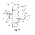
- a TE configuration 1200 has a plurality of first side TE elements 1201, 1202 of alternating conductivity types sandwiched in series between shunts 1203 and a plurality of second side shunts 1204, so that a current 1209 passes perpendicular to the breadth B B and width W B of the shunts rather than generally parallel to the breadth as in Figure 1C .
- the volume of the new configuration can be compared to that of Figure 1C .
- thermoelectric material A C ⁇ L C
- V B A B ⁇ L B
- V B V C A B A C ⁇ L B L C ⁇ 1 6.4 2 ⁇ / 41 1
- the TE stack configuration 1200 of Figure 12 has P-type TE elements 1201 and N-type TE elements 1202 of length L B 1205. The direction of current flow is indicated by the arrow 1209.
- the TE elements have a breadth B B and a width W B .
- PN shunts Between N -type 1202 and P -type 1201 elements, in the direction of current flow, are the first side shunts 1203 ("NP shunts").
- the PN shunts 1204 extend generally in the opposite direction from the stack 1200 than the NP shunts 1203. Angles other than 180° are also advantageous.
- NP shunts 1203 are cooled and PN shunts 1204 are heated.
- the parasitic electrical resistance losses for the configuration 1200 are lower typically than for the conventional configuration 100 of Figure 1 for the same TE element dimensions.
- the TE length L B 1205 is reduced to equate the ratio of parasitic electrical losses in the two configurations, the TE length L B 1205 will be smaller, and the configuration of Figure 12 advantageously can operate at higher power density than that of Figure 1 .
- the configuration 1200 of Figure 12 also uses less thermoelectric material, and can be more compact than in the conventional design of Figure 1 .
- the shunts 1203, 1204 can serve the dual function of transmitting thermal power away from the TE elements 1201, 1202 and exchange thermal power with an external object or medium, such as a working fluid.
- FIG. 13A An illustration of a preferred embodiment 1300 of a shunt combined to form a heat exchanger 1302 is depicted in Figure 13A .
- at least one TE element 1301 is electrically connected, such as with solder, to a raised electrode surface 1303 of a heat exchange shunt 1302.
- the shunt 1302 can be constructed primarily of a good thermal conductor, such as aluminum, and have integral clad overlay material 1304, 1305, made of a high-electrical conductivity material, such as copper, to facilitate TE element 1301 attachment and current flow at low resistance.
- Figure 13B depicts a detailed side view of a portion of a stack thermoelectric assembly 1310 made up of the thermoelectric shunts 1302 and TE elements 1301 of Figure 13A .
- a plurality of shunts 1302 with raised electrode surfaces 1303 are electrically connected in series to TE elements 1301 of alternating conductivity types.
- the shunts 1302 will be alternately heated and cooled when an appropriate current is applied.
- the thermal power produced is transported away from the TE elements 1301 by the shunts 1302.
- the raised electrodes 1303 facilitate reliable, low-cost, stable surfaces to which to attach the TE elements 1301.
- a stack of a plurality of these assemblies 1310 may be provided.
- An array of stacks could also be used which also further facilitates thermal isolation.
- the electrodes 1303 advantageously can be shaped to prevent solder from shorting out the TE elements 1301. Also, the electrodes 1303 advantageously can be shaped to control the contact area and hence, current density, through the TE elements 1301.
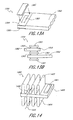
- FIG. 14 An example of a portion of a shunt heat exchanger 1400 is depicted in Figure 14 .
- This portion 1400 has increased surface area to aid heat transfer.
- a TE element 1401 is attached to a shunt 1402, preferably constructed as depicted in Figure 13A , or as in other embodiments in this application.
- Heat exchangers 1403, 1404, such as fins, are attached with good thermal contact, such as by brazing, to the shunt 1402.
- a working fluid 1405 passes through the heat exchangers 1403, 1404.
- the shunt portion 1400 is configured so that as the working fluid 1405 passes through the heat exchangers 1403, 1404, thermal power is transferred efficiently.
- the size of materials and proportions of the shunt 1402 and heat exchangers 1403, 1404 are designed to optimize operating efficiency when combined into a stack such as described in Figures 12 and 13B .
- the heat exchangers 1403, 1404 can be louvered, porous or be replaced by any other heat exchanger design that accomplishes the stated purposes such as those described in " Compact Heat Exchangers", Third Edition, by W. M. Kays and A. L. London .
- the heat exchangers 1403, 1404 can be attached to the shunt 1402 by epoxy, solder, braze, weld or any other attachment method that provides good thermal contact.
- the shunt segment 1500 is constructed of multiple shunt elements 1501, 1502, 1503 and 1504.
- the shunt elements 1501, 1502, 1503 and 1504 may be folded over, brazed, riveted to each other or connected in any other way that provides a low electrical resistance path for a current 1507 to pass and to provide low thermal resistance from a TE element 1506 to the shunts 1501, 1502, 1503 and 1504.
- the TE element 1506 is advantageously attached to segment 1500 at or near a base portion 1505.
- the shunt segment 1500 depicts a design alternative to the shunt segment 1400 of Figure 14 , and can be configured in stacks as depicted in Figures 12 and 13 , and then in arrays of stacks if desired. Both the configurations in Figures 14 and 15 can be automatically assembled to lower the labor cost of the TE systems made from these designs.
- Shunt segments can also be formed into stack assemblies 1600 as depicted in Figure 16 .
- Center shunts 1602 have first side TE elements 1601 of the same conductivity type at each end on a first side and second side TE elements 1605 of the opposite conductivity type at each end of the opposite side of the center shunts 1602.
- a right shunt 1603 and a left shunt 1604 are placed between each center shunt 1602 to form a stack of shunts 1602 .
- the right shunts 1603 are placed such that the left end is sandwiched between, the TE elements 1601, 1605 in good thermal and electrical contact.
- the left side shunts 1604 are positioned such that the right end is sandwiched between TE elements 1601, 1605, and are in good thermal and electrical contact.
- the shunts 1602, 1603 and 1604 are alternately stacked and electrically connected to form a shunt stack 1600.
- a first working fluid 1607 and a second working fluid 1608 pass through the assembly 1600.
- the stack may be, and likely will, consist of many additional shunt elements in the stack.
- the small portions of a stack assembly 1600 are merely depicted to provide the reader with an understanding. Further replication of such stacks is clear from the figures.
- additional stacks, thermally isolated in a direction of working fluid flow could be provided.
- the stack assembly 1600 forms a solid-state heat pump for conditioning fluids. It is important to note that the stack 1600 can have few or many segments and can thereby operate at different power levels, depending on the amount of current and voltage applied, component dimensions and the number of segments incorporated into the assembly. Arrays of such stacks may also be advantageous. In a situation where arrays of such stacks 1600 are used, it would be preferable to provide thermal isolation in the direction of fluid flow as described in U.S. Patent No. 6,539,725 for improved efficiency.
- shunts 1602, 1603, 1604 can be replaced by other shapes such as, but not limited to, those depicted in Figures 14 and 15 , to improve performance.
- a TE assembly 1700 is constructed of right side shunts 1703 and left side shunts 1704 to form a generally circular shape.
- the right side shunts 1703 are advantageously configured to form a partial circle as are the left side shunts 1704.
- the shunts which become cold during operation may be either larger or smaller than the shunts that become hot, depending on the particular goals of the device. It should be noted that the substantially circular configuration is not necessary, and other configurations of the shunt segments shown in Figure 17 to create a center flow portion could be used.
- the right side shunts could be half rectangles or half squares
- the left side shunts 1704 could be half rectangles or squares.
- one side could be multi-sided and one side could be arcuate.
- the particular shape of the shunts are changeable.
- the TE elements 1701 and 1702, of alternating conductivity type, as discussed for Figure 16 are electrically connected in series in the stack assembly 1700.
- a fluid 1712 passes into the central region formed by the shunts 1703, 1704.
- a first portion 1707 of the fluid 1712 passes between the right side shunts 1703 and a second portion 1706 of the working fluid 1712 passes between the left side shunts 1704.
- a power supply 1708 is electrically connected to the TE elements by wires 1712, 1713 that are connected to the stack at connections 1710 and 1711.
- a fan 1709 may be attached to one (or both) ends of the stack.
- a pump, blower, or the like could be used as well.
- the fan 1709 When power is applied to the fan 1709, it pumps the working fluid 1712 through the assembly 1700.
- the first fluid portion 1707 of working fluid 1712 is cooled as it passes through them.
- the second portion 1706 of working fluid is heated as it passes through heated left side shunts 1704.
- the assembly 1700 forms a simple, compact cooler/heater with a capacity and overall size that can be adjusted by the number of shunts 1703, 1704 utilized in its construction. It is apparent that the shunts 1703, 1704 could be angular, oval or of any other advantageous shape. Further, the shunts can be of the designs depicted in Figures 14 , 15 or any other useful configuration.
- thermoelectric system of Figures 12 , 14 , 15, 16 and 17 more than one TE element can be used in one or more portions of an array as is depicted in Figure 18 .
- TE elements 1801, 1804 are connected to raised electrode surfaces 1804 on each side of shunts 1802, 1803.
- a number of TE elements 1801, electrically in parallel, can increase mechanical stability, better distribute thermal power and add electrical redundancy to the system. More than two TE elements 1801 can be used in parallel.
- FIG. 19 One example of such a shunt is depicted in Figure 19 .
- an electrical insulation 1905 isolates an electrode portion 1903 of a shunt 1900 from a heat exchange portion 1904 of the shunt 1900.
- TE elements 1901, 1902 are preferably mounted on the electrode portion 1903.
- electrical potential is applied between TE elements 1901, 1902 of opposite conductivity types, through, advantageously, the electrode portion, 1903 made of a high electrical and thermal conductivity material, such as copper.
- Thermal power produced by the TE elements 1901, 1902 is conducted along the shunt electrode 1903, through the electrical insulation 1905, and into the heat exchange portion 1904 of the shunt 1900.
- the electrical insulation 1905 is a very good thermal conductor such as alumina, thermally conductive epoxy or the like.
- the interface shape formed by electrical insulation 1905 is a shallow "V" shape to minimize thermal resistance. Any other shape and material combination that has suitably low interfacial thermal resistance can be used as well.
- a stack of such shunts 1900 can be used as described previously.
- FIG. 20 An alternate form of electrical isolation is shown in another shunt segment 2000 assembly depicted in top view in Figure 20 .
- First TE elements 2001 are connected to a left shunt 2003 of shunt segment array 2000
- second TE elements 2002 are connected to a right shunt 2004 of shunt segment array 2000.
- Electrical insulation 2005 is positioned between left side shunt segments 2003 and right side shunt segments 2004.
- the configuration depicted in Figure 20 provides electrical isolation between TE elements 2001 and 2002 while retaining mechanical integrity of the overall shunt 2000.
- the electrical insulation 2005 need not provide particularly good thermal conductivity since the sources of thermal power, the TE elements 2001 and 2002, can cool or heat the left and right shunt segments 2003, 2004, at different levels, provided electrical insulation 2005 is on average centered between the TE elements 2001 and 2002.
- two TE elements 2001 and two second TE elements 2002 are depicted, a larger TE element or a larger number of TE elements on each side could be utilized.
- Two first TE elements 2001 and two second TE elements 2002 are merely selected for illustration of a good stable mechanical structure.
- the first TE element 2001 and the second TE elements 2002 need not be, but may be, of differing conductivity types.
- FIG. 21 An alternate method of achieving electrical isolation within a shunt 2100 is depicted in Figure 21 .
- a shunt portion 2103 with two first TE elements 2101 is mechanically attached to a second shunt portion 2104 with two second TE elements 2102.
- Electrical insulation 2106 mechanically attaches shunt portions 2103 and 2104, which are also separated from one another by a gap 2105.
- the electrical insulation 2106 need not be a good thermal conductor.
- the TE elements 2101 and 2102 each provide thermal power to the respective shunt portions 2103 and 2104.
- Electrical insulation 2106 can be adhesive-backed Kapton® tape, injection molded plastic, hot melt adhesive or any other suitable material.
- the shunt portions 2103 2104 do not overlap to form a lap joint. Such a joint, with epoxy or other electrically insulating bonding agent could also be used.
- FIG. 22 Another shunt segment array 2200, depicted in top view in Figure 22 , has electrically isolated shunt segments in a rectangular TE array 2200.
- First TE elements 2201 are thermally connected to first shunt portions 2202, and second TE elements 2203 are thermally connected to second shunt portions 2204.
- Each shunt portion is separated electrically from the other shunt portions by gaps 2210, 2211.
- Electrical insulation 2208 at the left side of the assembly, insulation 2207 in the middle and insulation 2209 on the right side are preferably provided.
- An arrow 2212 indicates working fluid flow direction. This configuration can be operated at higher voltage and lower current than a similar array without electrical isolation.
- first TE elements 2201 and second TE elements 2203 need not, but may be, of differing conductivity types. This will depend on the direction of desired current flow.
- the TE elements 2202, 2203 may, however, be at different potentials.
- the gaps 2210 serve to effectively thermally isolate first shunt portions 2202 from each other, and second shunt portions 2204 from each other.
- the side insulation 2208, 2209 provide both thermal and electrical isolation while mechanically attaching the shunts together.
- Center insulation 2207 provides electrical insulation and thermal isolation along its length.
- array 2200 is constructed to produce thermal isolation in the direction of arrow 2212 as described in U.S. Patent No. 6,539,725 . This configuration can be operated at higher voltage and lower current than a similar array without electrical isolation.
- a cooling system 2300 that employs shunt segment arrays generally of the type described in Figure 22 is depicted in Figure 23 .
- the cooling system 2300 has inner shunt segments 2301, 2302 connected mechanically by electrically insulating material 2320 such as tape.
- the inner shunt segments 2302 are mechanically connected by electrically and thermally insulating material 2321.
- the inner segments 2301 are mechanically connected by electrically and thermally insulating material 2307.
- the inner shunt segments 2301, 2302 separately are connected to TE elements at the ends (not shown) in a manner described for Figure 22 .
- the TEs are sandwiched in the stack between inner shunt segments 2301, 2302 and respective outer shunt segments 2303, 2305.
- the center shunt segments 2301 separately are connected to outer left shunt segments 2305, and the inner shunt segments 2302 are connected to right outer shunt segments 2303.
- the right outer shunt segments 2303 are similarly mechanically connected by electrically and thermally insulating material 2322 which is similar to electrically insulating material 2321 connecting the inner shunt segments 2302.
- the left outer shunt segments 2305 are similarly mechanically connected.
- a housing 2311 holds a stack array of shunt segments and TEs.
- Terminal posts 2312 and 2314 are electrically connected to inner segments 2301.
- terminals 2315 and 2316 connect to inner shunt segments 2302.
- thermally and electrically insulating spacers 2309, 2310 are positioned between each inner and outer segment.
- a first working fluid 2317 passes through the inner region and a second working fluid 2318, 2319 passes through the outer regions.
- the inner shunt segments 2301, 2302 are cooled.
- the outer shunt segments 2303, 2305 are heated.
- the working fluid 2317 passing through the inner region is cooled, and the working fluid 2318, 2319 passing through the outer shunt segments 2303, 2305 is heated.
- the housing 2311 and the insulators 2309, 2310 contain and separate the cooled fluid 2317 from the heated fluid 2318, 2319.
- each stack in the system 2300 can be in series to operate at high voltage, in series/parallel to operate at about half the voltage or in parallel to operate at about 1 ⁇ 4 the voltage.
- Polarity could be reversed to heat the inner working fluid 2317 and cool the outer working fluids 2318, 2319. More segments could be utilized in the direction of working fluids 2317, 2318, 2319 flow to operate at even higher voltage and to achieve higher efficiency from the resultant more effective thermal isolation.
- FIG. 24A and 24B Another compact design that achieves enhanced performance from thermal isolation uses combined shunt and heat transfer segments 2400 as depicted in Figure 24A and 24B .
- This design is very similar to that of Figure 14 , but with TE elements 2401, 2402 aligned in the general direction of fluid flow.
- the TE elements 2401, 2402 of opposite conductivity type are connected to an extension 2403 of a shunt 2404.
- heat exchangers 2405, 2406 such as fins, are in good thermal contact with the shunt 2404.
- a working fluid 2409 is heated or cooled as it passes through heat exchanger fins 2405, and 2406, depending on the direction of current flow.
- Figure 24B depicts a portion of a stack 2410 consisting of TE shunt segments 2400 as shown in Figure 24A .
- Current 2417 flows in the direction indicated by the arrow.
- a plurality of first side shunts 2400 and a plurality of second side shunts 2400a are connected to TE elements 2411.
- a first working fluid 2418 flows along the lower portion of stack 2410 through the heat exchangers on the second side shunts 2400a in Figure 24a , and a working fluid 2419 flows advantageously in the opposite direction through the heat exchangers of first side shunts 2400.
- the upper portion of the stack 2410 progressively cools fluid 2419 as it passes from one segment to the next, and the lower portion progressively heats fluid 2418 as it passes from one shunt 2400a to the next.
- FIG. 25A An alternative TE stack configuration 2500 is depicted in Figure 25A .
- This TE stack achieves the benefits of thermal isolation with a working fluid 2513 flowing generally perpendicular to the direction of current flow 2512.
- a first shunt 2502 is connected electrically to a first TE element 2501 and is in good Thermal contact with heat exchangers 2503, 2504.
- a second first side shunt 2506 is similarly in good thermal contact with its heat exchangers 2508, and a third first side shunt 2505 is in good thermal contact with its heat exchangers 2507.
- Interspersed between each first side shunt 2502, 2506 and 2505 are TE elements 2501 of alternating type and second side shunts 2509, 2510 and 2511 projecting generally in the opposite direction, as with Figure 12 .
- Second side shunts 2509, 2510 and 2511 are generally of the same shape and bear the same spatial relationship as first side shunts 2502, 2506 and 2505.
- a working fluid 2513 passes through the stack assembly in the direction indicated by the arrow.
- first side shunts 2502, 2505 and 2506 are heated and second side shunts 2509, 2510 and 2511 are cooled.
- the working fluid 2513 passes first through heat exchanger 2507, then through the heat exchanger 2508 and finally through the heat exchanger 2503, it is progressively heated.
- a full stack assembly has repeated sections of the array 2500, in the direction of current flow, assembled so that the top of heat exchanger 2503 would be spaced closely to the bottom of the next sequential heat exchanger 2504 of another array portion.
- the thermal isolation in the direction of working fluid 2513 flow is readily apparent.
- Figure 25B is a plan view of the array portion 2500 depicted in Figure 25A .
- the cooling of a plurality of TE elements 2501, alternating in conductivity type, are interspersed with the plurality of first side shunts 2502, 2506, 2505, and a plurality of second side shunts 2511, 2509 and 2510, so that the first side shunts 2502, 2506 and 2505 alternate with the second side shunts 2511, 2509 and 2510.
- the shunts are separated by gaps 2534 and are in good thermal contact with heat exchangers for each shunt.
- a first working fluid 2531 passes along the upper section from right to left and a working fluid 2532 passes advantageously from left to right along the lower section.
- Thermal and electrical insulation 2533 is preferably provided between each pair of shunts, except where the electrical current flows through the TEs and shunts.
- the working fluid 2531 When suitable current passes through the array 2500, for example, the working fluid 2531 is progressively heated and the working fluid 2532 is progressively cooled.
- the insulation 2533 prevents unnecessary thermal losses and also prevents the working fluids 2531, 2532 from mixing.
- the array 2500 operates in counter flow mode, and employs thermal isolation to enhance performance.
- the same array 2500 can operate with the working fluids 2531, 2532 moving in the same direction in parallel flow mode, and still have the benefits of thermal isolation to enhance performance.
- the TE elements 2521 are not all of the same resistance, but have resistances that vary depending on the temperature and power differentials between individual TE elements, as described in U.S. Patent No. 6,539,725 .
- FIG. 26A Another TE module 2600 is depicted in Figure 26A , that uses the principles discussed in the present description to achieve operation at higher voltages and possible other benefits such as higher power density, compact size, ruggedness, higher efficiency.
- a first TE element 2601 is sandwiched between a first end shunt 2603 and a second shunt 2604.
- a second TE element 2602, of opposite conductivity type is sandwiched between the second shunt 2604 and a third shunt 2605. This pattern is continued to final end shunt 2606.
- a current 2607 flows into final end shunt 2606, through the TE modules and out the first end shunt 2603, as indicated by arrows 2608 and 2609.
- Gaps 2611 prevent electrical conduction and reduce thermal conduction between adjacent shunts.
- the first end shunt 2603 and the final end shunt 2606 have an electrode surface 2612.
- the other shunts have shunt surfaces 2614 that are thermally conductive but electrically insulating
- suitable current 2608 passes through the TE module 2600 heating the upper surface and cooling the lower surface (or vice versa).
- the TE module 2600 depicted in Figure 26A consists of five TE elements and six shunts.
- any odd number of TE elements can be employed, spaced alternately with shunts as depicted.
- more than one TE element (of the same type as explained for Figure 18 ) may be connected in parallel between each pair of shunts.
- an even number of TEs can be used, such as to have electrical power confined to electrically isolated portions of one surface.
- FIG. 26B An array 2620 of TE modules 2600 is depicted in Figure 26B.
- Figure 26B depicts two TE modules 2600, of the type shown in Figure 26A , stacked on top of each other with a center heat transfer member 2635 sandwiched between first side shunts 2604.
- Outer heat transfer members 2632 and 2636 are thermally coupled to second side shunts 2605.
- the shunt and heat transfer members can also be of any other suitable types, for example, the types presented in Figures 14 and 15 .
- a first end shunt 2603 of a first TE module is electrically connected to the outer heat transfer members 2632.
- the other end shunt 2606 of the first or upper TE module is electrically connected to the center heat transfer member 2635.
- a second end shunt 2606a of the second TE module is electrically coupled to the center heat transfer member 2635 and the first end shunt 2603a of the second TE module is electrically coupled to the outer heat transfer member 2636 on the bottom of Figure 26B .
- the other shunts 2604, 2605 have electrical insulation 2612 that is thermally conductive.
- the shunts have gaps 2611 to electrically isolate them from one another. Current flow is indicated by the arrows 2628, 2629, 2630, 2631 and 2637.
- the TE elements 2601, 2602 alternate in conductivity type.
- second side shunts 2605 and the outer heat transfer members 2632 and 2636 are heated.
- the first side shunts 2604 and center heat transfer member 2635 are cooled.
- the opposite is true for reversed current.
- the operating current can be adjusted along with the corresponding voltage by adjusting the dimensions and number of TE elements 2601, 2602.
- power density can be adjusted.
- a larger number of shunts and TE elements could be used, which would widen the configuration shown in Figure 26B .
- further TE modules 2600 could be stacked in a vertical direction.
- an array of such stacks into or out of the plane of Figure 26B could be provided or any combination of the above could be utilized.
- thermal isolation principles in the direction of heat transfer or working fluid flow could be utilized in accordance with the description in U.S. Patent No. 6,539, 725 .
- FIG. 27 An alternative embodiment of a TE module 2700, similar in type to the TE module 2600 of Figure 26A , is illustrated in Figure 27 .
- End shunts 2705, 2704 are electrically connected to a power source 2720 and ground 2709.
- TE elements 2701, 2702 are electrically connected to between the series of shunts 2703, 2704, 2705, 2706.
- all shunts 2703, 2704, 2705, 2706 are electrically isolated by insulation 2711 from first and second heat transfer members 2707, 2708.
- the shunts are in good thermal contact with the heat transfer members 2707, 2708.
- First side heat transfer member 2708 moves in the direction indicated by an arrow 2712.
- the second side heat transfer member 2707 moves in the opposite direction, as indicated by an arrow 2710.
- the second side heat transfer member 2707 When suitable current is applied to the TE module 2700, the second side heat transfer member 2707 is cooled and the first side heat transfer member 2708 is heated. Operation is similar to that associated with the description of Figure 7A , 7B , 7C, and 7D . It should be noted that the first and second heat transfer members 2707, 2708, need not be rectangular in shape as might be inferred from Figure 27 , but may be disk shaped or any other advantageous shape, such as those discussed in Figure 7A . With effective design, the TE module 2700 can also achieve the performance benefits associated with thermal isolation as discussed in U.S. Patent No. 6,539,725 .
- heat transfer components 2707 and 2708 do not move.
- the TE module 2700 is similar to a standard module as depicted in Figure 1 , but can operate with a high power density and utilize relative thin TE elements 2701, 2702.
- the TE module 2700 induces low shear stresses on the TE elements 2701, 2702 that are produced by thermal expansion differences between the first side and second side shunts, for example. Because shear is generated in the TE module 2700 by the temperature differential across TE elements 2701, 2702, and is proportional to the width dimension, it can be much less than the shear in a standard TE module, in which the shear is proportional to the overall module width.
- Figure 27 also provides a good illustration to describe how the embodiments described in this specification can be used for power generation as well.
- the terminals 2709, 2720 are connected to a load rather than a power source in order to provide power to a load.
- the heat transfer members 2708, 2707 provide thermal power in the form of a temperature gradient.
- the temperature gradient between the first heat transfer member 2708 and second heat transfer member 2707 causes the thermoelectric system 2700 to generate a current at terminals 2709, 2720, which in turn would connect to a load or a power storage system.
- the system 2700 could operate as a power generator.
- the other configurations depicted in this description could also be coupled in similar manners to provide a power generation system by applying a temperature gradient and deriving a current.
- a TE heat transfer system 2800 is depicted in Figure 28 that uses a gas working fluid 2810, and a liquid working fluid 2806.
- first side shunt heat exchangers 2803 are of construction depicted in Figure 24A and Figure 24B .
- the shunt heat exchangers 2803 transfer thermal power with the gaseous working media 2810.
- second side shunts heat exchanger 2804, 2805 transfer thermal power with liquid working media 2806.
- a plurality of TE elements 2801 of opposite conductivity types are sandwiched between second side shunts 2804, 2805 and the shunt heat exchanger 2803.
- the second side shunt heat exchangers 2804, 2805 are similarly sandwiched between TE elements 2801 of alternating conductivity type.
- a current 2812, 2813 passes through the system 2800 as represented by the arrows 2812, 2813.
- tubes 2814, 2815 pass the liquid working media 2806 from one shunt heat exchanger 2804, 2805 to the next one.
- Operation of the TE heat transfer system 2800 is similar to that of the description of Figure 24B , with one working fluid 2810 being gaseous and the other 2806 being liquid.
- the benefits of thermal isolation as described in U.S. Patent No. 6,539,725 are also achieved with the design depicted in system 2800.
- Figure 29 depicts details of a shunt heat exchanger 2900.
- the assembly advantageously has a container 2901 constructed of very good thermally conductive material, an electrode 2902 constructed of very good electrically conductive material, and heat transfer fins 2905 and 2906 in good thermal contact with the top and bottom surfaces of container 2901.
- the container 2901 and the electrode 2902 are constructed of a single material, and could be unitary in construction.
- an interface 2904 between the bottom surface of container 2901 and electrode 2902 has very low electrical resistance. Fluid 2909 passes through the shunt heat exchanger 2900.
- TE elements are electrically connected to the top and bottom portions of the electrode 2902.
- the container 2901 and the fins 2905, 2906 are heated or cooled.
- the working fluid 2909 passing through the shunt heat exchanger 2900 is heated or cooled by the heat exchange 2900.
- the shunt heat exchanger 2900 is of sufficiently good electrical conductivity that it does not contribute significantly to parasitic losses. Such losses can be made smaller by minimizing the current path length through electrode 2902, maximizing electrical conductivity throughout the current path, and increasing electrode 2902 cross sectional area.
- the container 2901 top and bottom surfaces, and fins 2905 and 2906 provide sufficient electrical conductivity in the direction of current flow, that the solid electrode body 2902 can be reduced in cross sectional area or completely eliminated as shown in the embodiment in Figure 4B .
- a heat sink and fluid system 3000 is depicted in Figure 30 .
- TE elements 3001 of alternating conductivity types are interspersed between fluid heat exchanges 3004, each having shunt portions 3003, and shunts 3002 and 3005.
- Current 3006, 3007 flows through the shunt portions 3003, the shunts 3002 and 3005 and the TE elements 3001.
- a working fluid 3009 flows as indicated by the arrow.
- Heat sinks 3010, 3011 are in good thermal contact with and electrically insulated from the shunts 3002, 3005.
- electrical insulation 3008, 3012 that advantageously has good thermal conductance confines the current flow 3001, 3007 to the circuit path indicated.
- thermal power is transferred to the heat sinks 3010, 3011 and from the working fluid 3009.
- the shunt heat transfer members 3004 are thermally isolated from one another so that performance gains from thermal isolation are achieved with this embodiment.
- FIG. 31A An alternative shunt heat exchanger embodiment 3100 is depicted in Figure 31A .
- a shunt portion 3101 has electrodes 3102 for connection to TE elements (not shown) and heat transfer extensions 3108 in good thermal contact with heat exchangers 3103, such as fins.
- a fluid 3107 passes through the heat exchangers 3103.
- the shunt heat exchanger 3100 preferably has electrodes 3102 located generally centered between heat transfer extensions 3108.
- thermal power can flow into and out of the TE assemblies in two directions, and thus can increase heat transfer capacity by about a factor of two per TE element in comparison to the embodiment depicted in Figure 24A .
- the shunt side may have increased heat transfer characteristics such as by incorporation heat pipes, convective heat flow, or by utilizing any other method of enhancing heat transfer.
- Figure 31B depicts a heat transfer shunt assembly 3110 with a shunt 3111, electrodes 3112 and influent fluid ports 3113, 3114, and effluent fluid ports 3115, 3116.
- the heat transfer shunt assembly 3110 can have increased heat transfer capacity per TE element and more fluid transport capacity than the system depicted in Figure 29 .
- Figure 31C depicts a shunt assembly 3120 with shunt member 3121, electrodes 3122 and heat exchange surfaces 3123, 3124.
- the shunt assembly 3120 can have approximately two times the heat transfer capacity per TE assembly as the embodiment depicted in Figures 26A and 26B .
- stacks of shunt assemblies 3120 would alternate at approximately right angles to one another and the surfaces 3123, 3124 opposite one another would both be heated, for example, and the next pair of surfaces in the stack at about a right angle to the heated pair, would be cooled.
- the surfaces 3123, 3214 could be at other angles such as 120° and be interdispersed with shunts 2604 as depicted in Figure 26 . Any combination of multisided shunts is part of the inventions.
- thermoelectric elements discussed herein may be as thin as 5 microns to 1.2 mm in one general embodiment.
- theremoelectric elements may be between 20 microns and 300 microns thick, more preferably from 20 microns to 200 microns, and even from 20 microns to 100 microns.
- the thickness of the thermoelectric elements is between 100 microns and 600 microns. These thicknesses for the thermoelectric elements are substantially thinner than conventional thermoelectric systems.
- TE elements do not necessarily require the TE elements to be assembled into arrays or modules.
- TE elements are advantageously attached directly to heat transfer members, thereby reducing system complexity and cost.
- the TE elements could vary in size across the array or stack, the end type TE elements could be of different size and shape than the P type TE elements, some TE elements could be hetero structures while others could be non-hetero structure in design.
- the systems described in these figures do operate in both cooling/heating and power generation modes.
- specific changes can be implemented to optimize performance for cooling, heating or power generation.
- large temperature differentials (93°G to 1093°G) (200 to 2000° F)) are desirable to achieve high-efficiency in power generation as is well know in the art, while small temperature differentials -12°C to 15.6°C) (10 to 60° F)) are characteristic of cooling and heating systems.
- Large temperature differentials require different construction materials and possibly TE modules and elements of different design dimensions and materials. Nevertheless, the basic concept remains the same for the different modes of operation.
- the designs described in Figures 5 , 8 and 9 are advantageous for power generation because they offer the potential to fabricate simple, rugged, low-cost designs. However, all of the above mentioned designs can have merit for specific power generation applications and cannot be excluded.
Claims (34)
- Thermoelektrisches System mit:mehreren thermoelektrischen Modulen (1901, 1902), wobei mindestens einige der thermoelektrischen Module (1901, 1902) so bemessen sind, dass ein Betrieb mit hoher Leistungsdichte erfolgen kann;mehreren ersten Wärmeübertragungsvorrichtungen (1203) und mehreren zweiten Wärmeübertragungsvorrichtungen (1204), wobei mindestens einige der ersten Wärmeübertragungsvorrichtungen zwischen mindestens zwei der thermoelektrischen Module sandwichartig eingefügt sind und mindestens einige der zweiten Wärmeübertragungsvorrichtungen zwischen mindestens zwei der thermoelektrischen Module sandwichartig eingefügt sind, um eine Stapel-Konfiguration von thermoelektrischen Modulen mit alternierenden ersten und zweiten Wärmeübertragungsvorrichtungen zu bilden,dadurch gekennzeichnet, dass mindestens einige der ersten Wärmeübertragungsvorrichtungen (1203) einen ersten Abschnitt (2202) und einen mit dem ersten Abschnitt (2202) mechanisch verbundenen zweiten Abschnitt (2204) aufweisen, wobei der erste Abschnitt (2202) vom zweiten Abschnitt (2204), elektrisch getrennt ist.
- Thermoelektrisches System nach Anspruch 1, wobei mindestens einige der ersten Wärmeübertragungsvorrichtungen und mindestens einige der zweiten Wärmeübertragungsvorrichtungen von dem mindestens einen Stapel in unterschiedlichen Richtungen vorstehen und wobei mindestens einige der ersten oder zweiten Wärmeübertragungsvorrichtungen so angeordnet sind, dass eine thermische Trennung in der Richtung der Bewegung eines Arbeitsmediums erfolgt.
- Thermoelektrisches System nach Anspruch 2, ferner mit einer Stromquelle, die mit dem Stapel elektrisch gekoppelt ist, wobei der Strom mindestens einige der Wärmeübertragungsvorrichtungen und thermoelektrischen Module in Reihe durchströmt.
- Thermoelektrisches System nach Anspruch 2, wobei die Wärmeübertragungsvorrichtungen mindestens einige der thermoelektrischen Module von mindestens einigen anderen der thermoelektrischen Module thermisch trennen.
- Thermoelektrisches System nach Anspruch 2, wobei das Arbeitsmedium ein Arbeitsfluid aufweist.
- Thermoelektrisches System nach Anspruch 2, wobei mindestens einige der Wärmeübertragungsvorrichtungen Wärmetauscher mit mehreren Wärmetauscherelementen sind.
- Thermoelektrisches System nach Anspruch 2, wobei der erste Abschnitt einen Elektrodenabschnitt (1903) aufweist und der zweite Abschnitt einen Überbrückungsabschnitt (1904) aufweist, wobei der Elektrodenabschnitt (1903) von dem Überbrückungsabschnitt (1904) elektrisch getrennt und mit ihm thermisch gekoppelt ist.
- Thermoelektrisches System nach Anspruch 2, wobei mindestens einige der thermoelektrischen Module thermoelektrische Elemente aufweisen.
- Thermoelektrisches System nach Anspruch 8, wobei die thermoelektrischen Elemente alternierende p-leitende und n-leitende thermoelektrische Elemente aufweisen.
- Thermoelektrisches System nach Anspruch 2, wobei die Richtung der Bewegung des Arbeitsmediums von einem ersten Stapel zu einem zweiten Stapel verläuft.
- Thermoelektrisches System nach Anspruch 2, wobei die Richtung der Bewegung des Arbeitsmediums im Allgemeinen in der Richtung des mindestens einen Stapels verläuft.
- Thermoelektrisches System nach Anspruch 1, wobei mindestens einige der ersten Wärmeübertragungsvorrichtungen und mindestens einige der zweiten Wärmeübertragungsvorrichtungen von dem mindestens einen Stapel vorstehen und wobei mindestens die ersten oder zweiten Wärmeübertragungsvorrichtungen mindestens ein Medium aufnehmen, wobei das Medium eine Flüssigkeit und/oder ein Festkörper ist.
- Thermoelektrisches System nach Anspruch 12, wobei mindestens einige der ersten Wärmeübertragungsvorrichtungen und mindestens einige der zweiten Wärmeübertragungsvorrichtungen von dem mindestens einen Stapel in unterschiedlichen Richtungen vorstehen.
- Thermoelektrisches System nach Anspruch 12, wobei mindestens einige der ersten Wärmeübertragungsvorrichtungen ein erstes Medium aufnehmen und mindestens einige der zweiten Wärmeübertragungsvorrichtungen ein zweites Medium aufnehmen, wobei das erste Medium eine Flüssigkeit und/oder ein Festkörper ist und das zweite Medium aus einer Gruppe ausgewählt ist, die aus einer Flüssigkeit, einem Festkörper, einem Gas oder irgendeiner Kombination aus einer Flüssigkeit, einem Festkörper und einem Gas besteht.
- Thermoelektrisches System nach Anspruch 12, wobei das erste Medium flüssig ist und das zweite Medium ein Gas ist.
- Thermoelektrisches System nach Anspruch 12, wobei das mindestens eine Medium sich bewegt und mindestens einige der ersten oder zweiten Wärmeübertragungsvorrichtungen so angeordnet sind, dass eine thermische Trennung in Richtung der Bewegung des mindestens einen Mediums erfolgt.
- Thermoelektrisches System nach Anspruch 12, ferner mit einer Stromquelle, die mit dem Stapel elektrisch gekoppelt ist, wobei der Strom durch die Wärmeübertragungsvorrichtungen und die thermoelektrischen Module fließt.
- Thermoelektrisches System nach Anspruch 12, wobei mindestens einige der ersten thermoelektrischen Module p-leitende thermoelektrische Elemente aufweisen und mindestens einige der zweiten thermoelektrischen Module n-leitende thermoelektrische Elemente aufweisen und wobei die Wärmeübertragungsvorrichtungen mindestens einige der p-leitenden thermoelektrischen Elemente von mindestens einigen der n-leitenden thermoelektrischen Elemente thermisch trennen.
- Thermoelektrisches System nach Anspruch 12, wobei das mindestens eine Medium ein sich bewegendes Arbeitsmedium ist.
- Thermoelektrisches System nach Anspruch 12, wobei es sich bei der mindestens einen Wärmeübertragungsvorrichtung um Wärmetauscher mit Wärmetauscherelementen handelt.
- Thermoelektrisches System nach Anspruch 12, wobei der erste Abschnitt einen Elektrodenabschnitt (1903) aufweist und der zweite Abschnitt einen Überbrückungsabschnitt (1904) aufweist, wobei der Elektrodenabschnitt (1903) von dem Überbrückungsabschnitt (1904) elektrisch getrennt und mit ihm thermisch gekoppelt ist.
- Thermoelektrisches System nach Anspruch 1, wobei mindestens einige der mehreren thermoelektrischen Module n-leitende thermoelektrische Elemente sind und mindestens einige der thermoelektrischen Module p-leitende thermoelektrische Elemente sind.
- Thermoelektrisches System nach Anspruch 22, wobei mindestens einige der n-leitenden und/oder p-leitenden thermoelektrischen Elemente zwischen 5 µm und 1,2 mm dick sind.
- Thermoelektrisches System nach Anspruch 23, wobei mindestens einige der n-leitenden und/oder p-leitenden thermoelektrischen Elemente ein Verhältnis von Fläche zu Länge in der Richtung des Stromflusses der thermoelektrischen Elemente haben, wobei das Verhältnis etwa 6:1 ist.
- Thermoelektrisches System nach Anspruch 23, wobei mindestens einige der n-leitenden und/oder p-leitenden thermoelektrischen Elemente zwischen 20 µm und 300 µm dick sind.
- Thermoelektrisches System nach Anspruch 23, wobei mindestens einige der n-leitenden und/oder p-leitenden thermoelektrischen Elemente zwischen 20 µm und 200 µm dick sind.
- Thermoelektrisches System nach Anspruch 23, wobei mindestens einige der n-leitenden und/oder p-leitenden thermoelektrischen Elemente zwischen 20 µm und 100 µm dick sind.
- Thermoelektrisches System nach Anspruch 23, wobei mindestens einige der n-leitenden und/oder p-leitenden thermoelektrischen Elemente zwischen 100 µm und 600 µm dick sind.
- Thermoelektrisches System nach Anspruch 1, wobei mindestens einige der ersten oder zweiten Wärmeübertragungsvorrichtungen so angeordnet sind, dass eine thermische Trennung in der Strömungsrichtung eines Arbeitsmediums erfolgt.
- Thermoelektrisches System nach Anspruch 1, ferner mit einer Stromquelle, die mit dem Stapel elektrisch gekoppelt ist, wobei der Strom die Wärmeübertragungsvorrichtungen und thermoelektrischen Module in Reihe durchströmt.
- Thermoelektrisches System nach Anspruch 22, wobei die Wärmeübertragungsvorrichtungen mindestens einige der p-leitenden thermoelektrischen Elemente von mindestens einigen der n-leitenden thermoelektrischen Elemente thermisch trennen.
- Thermoelektrisches System nach Anspruch 1, wobei mindestens einige der Wärmeübertragungsvorrichtungen ein sich bewegendes Arbeitsfluid aufnehmen.
- Thermoelektrisches System nach Anspruch 32, wobei mindestens einige der Wärmeübertragungsvorrichtungen Wärmeaustauscher sind, die ein Gehäuse mit Wärmetauscherelementen im Inneren aufweisen.
- Thermoelektrisches System nach Anspruch 21, wobei der erste Abschnitt einen Elektrodenabschnitt (1903) aufweist und der zweite Abschnitt einen Überbrückungsabschnitt (1904) aufweist, wobei der Elektrodenabschnitt (1903) von dem Überbrückungsabschnitt (1904) elektrisch getrennt und mit ihm thermisch gekoppelt ist.
Applications Claiming Priority (2)
| Application Number | Priority Date | Filing Date | Title |
|---|---|---|---|
| US10/642,773 US6959555B2 (en) | 2001-02-09 | 2003-08-18 | High power density thermoelectric systems |
| PCT/US2004/026757 WO2005020340A2 (en) | 2003-08-18 | 2004-08-17 | High power density thermoelectric systems |
Publications (2)
| Publication Number | Publication Date |
|---|---|
| EP1665402A2 EP1665402A2 (de) | 2006-06-07 |
| EP1665402B1 true EP1665402B1 (de) | 2013-07-31 |
Family
ID=34216365
Family Applications (1)
| Application Number | Title | Priority Date | Filing Date |
|---|---|---|---|
| EP04781451.2A Not-in-force EP1665402B1 (de) | 2003-08-18 | 2004-08-17 | Thermoelektrische systeme mit grosser leistungsdichte |
Country Status (5)
| Country | Link |
|---|---|
| US (3) | US6959555B2 (de) |
| EP (1) | EP1665402B1 (de) |
| JP (1) | JP4994034B2 (de) |
| CN (1) | CN100456507C (de) |
| WO (1) | WO2005020340A2 (de) |
Families Citing this family (134)
| Publication number | Priority date | Publication date | Assignee | Title |
|---|---|---|---|---|
| US6672076B2 (en) | 2001-02-09 | 2004-01-06 | Bsst Llc | Efficiency thermoelectrics utilizing convective heat flow |
| US7273981B2 (en) | 2001-02-09 | 2007-09-25 | Bsst, Llc. | Thermoelectric power generation systems |
| US7942010B2 (en) | 2001-02-09 | 2011-05-17 | Bsst, Llc | Thermoelectric power generating systems utilizing segmented thermoelectric elements |
| US6959555B2 (en) * | 2001-02-09 | 2005-11-01 | Bsst Llc | High power density thermoelectric systems |
| US7231772B2 (en) | 2001-02-09 | 2007-06-19 | Bsst Llc. | Compact, high-efficiency thermoelectric systems |
| US7946120B2 (en) | 2001-02-09 | 2011-05-24 | Bsst, Llc | High capacity thermoelectric temperature control system |
| US7426835B2 (en) | 2001-08-07 | 2008-09-23 | Bsst, Llc | Thermoelectric personal environment appliance |
| US8490412B2 (en) * | 2001-08-07 | 2013-07-23 | Bsst, Llc | Thermoelectric personal environment appliance |
| US6812395B2 (en) | 2001-10-24 | 2004-11-02 | Bsst Llc | Thermoelectric heterostructure assemblies element |
| US20110209740A1 (en) * | 2002-08-23 | 2011-09-01 | Bsst, Llc | High capacity thermoelectric temperature control systems |
| US8227682B2 (en) * | 2003-04-17 | 2012-07-24 | Watts Thermoelectric, Llc | Same plane multiple thermoelectric mounting system |
| US7380586B2 (en) | 2004-05-10 | 2008-06-03 | Bsst Llc | Climate control system for hybrid vehicles using thermoelectric devices |
| US7694694B2 (en) * | 2004-05-10 | 2010-04-13 | The Aerospace Corporation | Phase-change valve apparatuses |
| US8642353B2 (en) * | 2004-05-10 | 2014-02-04 | The Aerospace Corporation | Microfluidic device for inducing separations by freezing and associated method |
| US7721762B2 (en) * | 2004-06-24 | 2010-05-25 | The Aerospace Corporation | Fast acting valve apparatuses |
| US7686040B2 (en) * | 2004-06-24 | 2010-03-30 | The Aerospace Corporation | Electro-hydraulic devices |
| US7650910B2 (en) * | 2004-06-24 | 2010-01-26 | The Aerospace Corporation | Electro-hydraulic valve apparatuses |
| US7587901B2 (en) | 2004-12-20 | 2009-09-15 | Amerigon Incorporated | Control system for thermal module in vehicle |
| US7743614B2 (en) | 2005-04-08 | 2010-06-29 | Bsst Llc | Thermoelectric-based heating and cooling system |
| US8039726B2 (en) * | 2005-05-26 | 2011-10-18 | General Electric Company | Thermal transfer and power generation devices and methods of making the same |
| US7847179B2 (en) | 2005-06-06 | 2010-12-07 | Board Of Trustees Of Michigan State University | Thermoelectric compositions and process |
| US9006556B2 (en) | 2005-06-28 | 2015-04-14 | Genthem Incorporated | Thermoelectric power generator for variable thermal power source |
| US8783397B2 (en) | 2005-07-19 | 2014-07-22 | Bsst Llc | Energy management system for a hybrid-electric vehicle |
| CN101292125A (zh) * | 2005-08-25 | 2008-10-22 | 开利公司 | 用于热电应用的换热器 |
| EP1996341B1 (de) * | 2006-02-20 | 2018-09-26 | Kang N. Lee | Artikel mit umgebungsbarriere-beschichtungssystem |
| TWM297010U (en) * | 2006-03-06 | 2006-09-01 | Channel Well Technology Co Ltd | Double-effect thermoelectric cooling apparatus |
| US7870745B2 (en) | 2006-03-16 | 2011-01-18 | Bsst Llc | Thermoelectric device efficiency enhancement using dynamic feedback |
| US7952015B2 (en) | 2006-03-30 | 2011-05-31 | Board Of Trustees Of Michigan State University | Pb-Te-compounds doped with tin-antimony-tellurides for thermoelectric generators or peltier arrangements |
| EP2378577A3 (de) | 2006-07-28 | 2012-12-05 | Bsst Llc | Thermoelektrisches Stromerzeugungssystem mit segmentierten thermoelektrischen Elementen |
| CN101517764B (zh) * | 2006-07-28 | 2011-03-30 | Bsst有限责任公司 | 高容量热电温度控制系统 |
| US7849692B2 (en) * | 2006-07-31 | 2010-12-14 | Caterpillar Inc | Segmented heat exchanger |
| US7779639B2 (en) | 2006-08-02 | 2010-08-24 | Bsst Llc | HVAC system for hybrid vehicles using thermoelectric devices |
| US20100155018A1 (en) * | 2008-12-19 | 2010-06-24 | Lakhi Nandlal Goenka | Hvac system for a hybrid vehicle |
| US7788933B2 (en) * | 2006-08-02 | 2010-09-07 | Bsst Llc | Heat exchanger tube having integrated thermoelectric devices |
| US8222511B2 (en) | 2006-08-03 | 2012-07-17 | Gentherm | Thermoelectric device |
| US20080087316A1 (en) | 2006-10-12 | 2008-04-17 | Masa Inaba | Thermoelectric device with internal sensor |
| CA2570928C (en) * | 2006-12-12 | 2014-05-13 | Randall H. Reid | Self-powered heat transfer fan |
| US20080289677A1 (en) * | 2007-05-25 | 2008-11-27 | Bsst Llc | Composite thermoelectric materials and method of manufacture |
| CN104990301B (zh) | 2007-05-25 | 2019-04-16 | 詹思姆公司 | 分配式热电加热和冷却的系统和方法 |
| WO2008154362A2 (en) * | 2007-06-08 | 2008-12-18 | David Reginald Carver | Device and method for converting thermal energy into electrical energy |
| US7765811B2 (en) * | 2007-06-29 | 2010-08-03 | Laird Technologies, Inc. | Flexible assemblies with integrated thermoelectric modules suitable for use in extracting power from or dissipating heat from fluid conduits |
| US9105809B2 (en) | 2007-07-23 | 2015-08-11 | Gentherm Incorporated | Segmented thermoelectric device |
| KR100842040B1 (ko) * | 2007-07-26 | 2008-06-30 | (주)디오시스엠엔엠 | 피부치료장치 |
| WO2009036077A1 (en) | 2007-09-10 | 2009-03-19 | Amerigon, Inc. | Operational control schemes for ventilated seat or bed assemblies |
| US8633371B2 (en) | 2007-11-09 | 2014-01-21 | The Boeing Company | Device and method for generating electrical power |
| US7914271B2 (en) | 2007-11-29 | 2011-03-29 | Husky Injection Molding Systems Ltd. | Gate insert heating and cooling |
| BRPI0906885A2 (pt) * | 2008-01-14 | 2019-09-24 | The Ohio State University Research Foundation | materiais e dispositivo termoelétricos e métodos de fabrico e de uso de dispositivo termoelétrico |
| US8677767B2 (en) * | 2008-01-28 | 2014-03-25 | Tayfun Ilercil | Thermo-electric heat pump systems |
| US9115919B2 (en) * | 2009-01-28 | 2015-08-25 | Micro Q Technologies | Thermo-electric heat pump systems |
| US20230272949A1 (en) * | 2008-01-28 | 2023-08-31 | Ambassador Asset Management Limited Partnership | Thermo-electric heat pump systems |
| WO2009097572A1 (en) | 2008-02-01 | 2009-08-06 | Amerigon Incorporated | Condensation and humidity sensors for thermoelectric devices |
| US8519254B2 (en) * | 2008-04-08 | 2013-08-27 | The Boeing Company | Device and method for generating electrical power |
| CN102077374A (zh) * | 2008-04-24 | 2011-05-25 | Zt普拉斯公司 | 结合增加的功率因数和减小的热导率的改进的热电材料 |
| US8650886B2 (en) * | 2008-09-12 | 2014-02-18 | Rockwell Collins, Inc. | Thermal spreader assembly with flexible liquid cooling loop having rigid tubing sections and flexible tubing sections |
| US8616266B2 (en) | 2008-09-12 | 2013-12-31 | Rockwell Collins, Inc. | Mechanically compliant thermal spreader with an embedded cooling loop for containing and circulating electrically-conductive liquid |
| EP2315987A2 (de) | 2008-06-03 | 2011-05-04 | Bsst Llc | Thermoelektrische wärmepumpe |
| BRPI0923671A2 (pt) * | 2008-06-10 | 2013-07-30 | Phillip C Watts | gerador termoelÉtrico |
| US20100006132A1 (en) * | 2008-07-14 | 2010-01-14 | Lucent Technologies, Inc. | Stacked Thermoelectric Modules |
| CN104523071A (zh) | 2008-07-18 | 2015-04-22 | 金瑟姆股份公司 | 气候受控床组件 |
| US20100024859A1 (en) * | 2008-07-29 | 2010-02-04 | Bsst, Llc. | Thermoelectric power generator for variable thermal power source |
| EP2333829A3 (de) | 2008-08-01 | 2013-11-27 | Bsst Llc | Erweiterte thermisch isolierte thermoelektrika |
| US8193440B1 (en) * | 2008-08-27 | 2012-06-05 | Hajjar Hussein M A | Hybrid electric generator |
| US9555686B2 (en) | 2008-10-23 | 2017-01-31 | Gentherm Incorporated | Temperature control systems with thermoelectric devices |
| US8613200B2 (en) | 2008-10-23 | 2013-12-24 | Bsst Llc | Heater-cooler with bithermal thermoelectric device |
| US9447994B2 (en) | 2008-10-23 | 2016-09-20 | Gentherm Incorporated | Temperature control systems with thermoelectric devices |
| US8359871B2 (en) * | 2009-02-11 | 2013-01-29 | Marlow Industries, Inc. | Temperature control device |
| US20100258154A1 (en) * | 2009-04-13 | 2010-10-14 | The Ohio State University | Thermoelectric alloys with improved thermoelectric power factor |
| KR102218137B1 (ko) | 2009-05-18 | 2021-02-22 | 젠썸 인코포레이티드 | 열전기 가열 및 냉각 시스템 |
| EP2433192B2 (de) | 2009-05-18 | 2020-08-26 | Gentherm Incorporated | Temperaturregelungssystem mit thermoelektrischem element |
| KR101344624B1 (ko) * | 2009-06-16 | 2013-12-26 | 에이비비 테크놀로지 아게 | 전기 구성품의 냉각 |
| DE102009058550A1 (de) * | 2009-07-21 | 2011-01-27 | Emcon Technologies Germany (Augsburg) Gmbh | Thermoelektrisches Modul, Baugruppe mit Modul, thermoelektrische Generatoreinheit und Abgasleitungsvorrichtung mit Generatoreinheit |
| IN2012DN00830A (de) | 2009-07-24 | 2015-06-26 | Bsst Llc | |
| US20110030754A1 (en) * | 2009-08-06 | 2011-02-10 | Laird Technologies, Inc. | Thermoelectric modules and related methods |
| DE102010004200A1 (de) | 2010-01-08 | 2011-07-14 | Emitec Gesellschaft für Emissionstechnologie mbH, 53797 | Vorrichtung zur Erzeugung elektrischer Energie aus einem wärmeleitenden Material |
| JP5444260B2 (ja) | 2010-01-19 | 2014-03-19 | 株式会社東芝 | 熱電モジュール及び発電装置 |
| US20110248209A1 (en) | 2010-03-12 | 2011-10-13 | Northwestern University | Thermoelectric figure of merit enhancement by modification of the electronic density of states |
| US20130199591A1 (en) * | 2010-03-30 | 2013-08-08 | Tata Steel Uk Limited | Arrangement for Generating Electricity with Thermoplastic Generators and Solar Energy Collector Means |
| US20110277473A1 (en) * | 2010-05-14 | 2011-11-17 | Geoffrey Courtright | Thermal Energy Transfer System |
| DE102010021901A1 (de) * | 2010-05-28 | 2011-12-01 | Volkswagen Ag | Wärmetauschen zwischen Fluidströmen mittels einer thermoelektrischen Vorrichtung |
| US9121414B2 (en) | 2010-11-05 | 2015-09-01 | Gentherm Incorporated | Low-profile blowers and methods |
| DE102010056170A1 (de) * | 2010-12-24 | 2012-06-28 | Volkswagen Ag | Thermoelektrisches Wärmetauschen |
| US8649179B2 (en) | 2011-02-05 | 2014-02-11 | Laird Technologies, Inc. | Circuit assemblies including thermoelectric modules |
| RU2444814C1 (ru) * | 2011-03-29 | 2012-03-10 | Юрий Феликсович Верниковский | Термоэлектрический кластер, способ его работы, устройство соединения в нем активного элемента с теплоэлектропроводом, генератор (варианты) и тепловой насос (варианты) на его основе |
| WO2012135734A2 (en) | 2011-04-01 | 2012-10-04 | Zt Plus | Thermoelectric materials having porosity |
| US9006557B2 (en) | 2011-06-06 | 2015-04-14 | Gentherm Incorporated | Systems and methods for reducing current and increasing voltage in thermoelectric systems |
| KR101654587B1 (ko) * | 2011-06-06 | 2016-09-06 | 젠썸 인코포레이티드 | 카트리지 기반 열전 시스템 |
| KR101991650B1 (ko) | 2011-07-11 | 2019-06-20 | 젠썸 인코포레이티드 | 전기 장치들의 열전 기반 열 관리 |
| CN102306701B (zh) * | 2011-09-22 | 2013-05-08 | 华南理工大学 | 一种长程集中冷却动力热电偶转换元件 |
| US9685599B2 (en) | 2011-10-07 | 2017-06-20 | Gentherm Incorporated | Method and system for controlling an operation of a thermoelectric device |
| KR101401065B1 (ko) * | 2011-12-15 | 2014-05-30 | 현대자동차주식회사 | 차량용 열전 발전기 |
| WO2013109988A2 (en) * | 2012-01-20 | 2013-07-25 | Gentherm Incorporated | Catalyst-thermoelrctrics generator integration |
| US9989267B2 (en) | 2012-02-10 | 2018-06-05 | Gentherm Incorporated | Moisture abatement in heating operation of climate controlled systems |
| US9388740B2 (en) * | 2012-02-15 | 2016-07-12 | The Boeing Company | Thermoelectric generator in turbine engine nozzles |
| WO2013164307A1 (en) | 2012-04-30 | 2013-11-07 | Universite Catholique De Louvain | Thermoelectric conversion module and method for making it |
| US9306143B2 (en) | 2012-08-01 | 2016-04-05 | Gentherm Incorporated | High efficiency thermoelectric generation |
| DE102012214701A1 (de) * | 2012-08-17 | 2014-02-20 | Behr Gmbh & Co. Kg | Thermoelektrische Vorrichtung |
| DE102012214704A1 (de) | 2012-08-17 | 2014-03-27 | Behr Gmbh & Co. Kg | Thermoelektrisches Modul |
| DE102012214700A1 (de) * | 2012-08-17 | 2014-02-20 | Behr Gmbh & Co. Kg | Thermoelektrischer Wärmetauscher |
| DE102012214702A1 (de) | 2012-08-17 | 2014-02-20 | Behr Gmbh & Co. Kg | Thermoelektrische Vorrichtung |
| IN2015DN01327A (de) * | 2012-09-27 | 2015-07-03 | Jfe Steel Corp | |
| US9360240B2 (en) * | 2012-11-09 | 2016-06-07 | Laird Technologies, Inc. | Thermoelectric assembly |
| TW201422903A (zh) * | 2012-12-10 | 2014-06-16 | Ind Tech Res Inst | 熱電發電裝置與熱電發電系統 |
| KR20140083335A (ko) * | 2012-12-26 | 2014-07-04 | 현대자동차주식회사 | 열전소자가 구비된 열교환기 |
| KR102034337B1 (ko) | 2013-01-14 | 2019-10-18 | 젠썸 인코포레이티드 | 전기 디바이스의 열전 기반 열 관리 |
| US10270141B2 (en) | 2013-01-30 | 2019-04-23 | Gentherm Incorporated | Thermoelectric-based thermal management system |
| KR102033212B1 (ko) | 2013-10-29 | 2019-10-16 | 젠썸 인코포레이티드 | 열전장치를 갖는 배터리 열 관리 |
| US9662962B2 (en) | 2013-11-05 | 2017-05-30 | Gentherm Incorporated | Vehicle headliner assembly for zonal comfort |
| EP2881195A1 (de) * | 2013-12-03 | 2015-06-10 | Loramendi, S.COOP. | Anlage zum Härten von Formkernen |
| KR20150075122A (ko) * | 2013-12-18 | 2015-07-03 | 현대자동차주식회사 | 열전소자가 구비된 열교환기 |
| KR102051617B1 (ko) | 2014-02-14 | 2019-12-03 | 젠썸 인코포레이티드 | 전도식 대류식 기온 제어 시트 |
| DE102014203176A1 (de) * | 2014-02-21 | 2015-09-10 | MAHLE Behr GmbH & Co. KG | Thermoelektrische Vorrichtung, insbesondere thermoelektrischer Generator oder Wärmepumpe |
| WO2015200520A1 (en) * | 2014-06-24 | 2015-12-30 | Spectrum Brands, Inc. | Electric grooming appliance |
| KR102226353B1 (ko) | 2014-09-12 | 2021-03-10 | 젠썸 인코포레이티드 | 흑연 열전기적 및/또는 저항성 열 관리 시스템 및 방법 |
| KR102330197B1 (ko) * | 2014-10-15 | 2021-11-23 | 엘지이노텍 주식회사 | 열전환장치 |
| CN107251247B (zh) | 2014-11-14 | 2021-06-01 | 查尔斯·J·柯西 | 加热和冷却技术 |
| US11857004B2 (en) | 2014-11-14 | 2024-01-02 | Gentherm Incorporated | Heating and cooling technologies |
| US11639816B2 (en) | 2014-11-14 | 2023-05-02 | Gentherm Incorporated | Heating and cooling technologies including temperature regulating pad wrap and technologies with liquid system |
| DE112015005666T5 (de) | 2014-12-19 | 2017-09-14 | Gentherm Incorporated | Thermische Konditionierungssysteme und -verfahren für Fahrzeugbereiche |
| WO2016134285A1 (en) * | 2015-02-19 | 2016-08-25 | Novus Energy Technologies, Inc. | Large footprint, high power density thermoelectric modules for high temperature applications |
| CN104779340A (zh) * | 2015-03-14 | 2015-07-15 | 浙江大学 | 基于高导石墨烯连接材料的温差发电装置 |
| DE102015210398A1 (de) * | 2015-06-05 | 2016-12-08 | Bombardier Transportation Gmbh | Thermoelektrischer Generator zur Umwandlung von Wärme eines heißen Gasstroms in elektrische Energie |
| US10625566B2 (en) | 2015-10-14 | 2020-04-21 | Gentherm Incorporated | Systems and methods for controlling thermal conditioning of vehicle regions |
| US10622532B2 (en) * | 2016-02-18 | 2020-04-14 | Mitsubishi Electric Corporation | Thermoelectric conversion module and method of manufacturing the same |
| WO2017165486A1 (en) * | 2016-03-22 | 2017-09-28 | Gentherm Inc. | Distributed thermoelectrics with non-uniform thermal transfer characteristics |
| CN106224124B (zh) * | 2016-09-08 | 2018-01-19 | 哈尔滨工程大学 | 一种基于塞贝克效应的热机装置 |
| JP6747937B2 (ja) * | 2016-10-25 | 2020-08-26 | ヤンマーパワーテクノロジー株式会社 | 熱電発電システム |
| EP3823052A4 (de) * | 2018-07-09 | 2022-04-06 | LG Innotek Co., Ltd. | Wärmeumwandlungsvorrichtung |
| US11075331B2 (en) | 2018-07-30 | 2021-07-27 | Gentherm Incorporated | Thermoelectric device having circuitry with structural rigidity |
| US11152557B2 (en) | 2019-02-20 | 2021-10-19 | Gentherm Incorporated | Thermoelectric module with integrated printed circuit board |
| US10857853B2 (en) * | 2019-05-01 | 2020-12-08 | GM Global Technology Operations LLC | Adaptive radiant heating system and method for achieving vehicle occupant thermal comfort |
| US10857852B2 (en) * | 2019-05-01 | 2020-12-08 | GM Global Technology Operations LLC | Adaptive radiant heating for a vehicle |
| TWI714149B (zh) * | 2019-07-01 | 2020-12-21 | 致茂電子股份有限公司 | 溫度控制電路以及溫度控制系統 |
| CN112345582A (zh) * | 2020-11-05 | 2021-02-09 | 福州大学至诚学院 | 一种半导体制冷片性能参数测试方法 |
| CN112542963A (zh) * | 2020-12-04 | 2021-03-23 | 中国电力科学研究院有限公司 | 一种温差发电器及发电模块 |
Family Cites Families (223)
| Publication number | Priority date | Publication date | Assignee | Title |
|---|---|---|---|---|
| US3126116A (en) | 1964-03-24 | Check valveb nipple | ||
| US600225A (en) * | 1898-03-08 | Automatic offset mechanism for sawmill-carriages | ||
| GB817077A (en) | 1956-08-22 | 1959-07-22 | Gen Electric | Improvements in or relating to thermoelectric cooling units |
| DE281459C (de) | 1912-04-03 | |||
| GB231192A (en) | 1924-03-21 | 1926-05-06 | Alice Sandberg | Improvements in regenerative preheaters for air or other media |
| US2027534A (en) | 1933-08-05 | 1936-01-14 | Charles B Ingersoll | Stud bolt wrench |
| US2944404A (en) | 1957-04-29 | 1960-07-12 | Minnesota Mining & Mfg | Thermoelectric dehumidifying apparatus |
| DE1071177B (de) | 1958-01-17 | |||
| US2949014A (en) | 1958-06-02 | 1960-08-16 | Whirlpool Co | Thermoelectric air conditioning apparatus |
| US2992538A (en) * | 1959-02-13 | 1961-07-18 | Licentia Gmbh | Thermoelectric system |
| US3006979A (en) | 1959-04-09 | 1961-10-31 | Carrier Corp | Heat exchanger for thermoelectric apparatus |
| US3129116A (en) | 1960-03-02 | 1964-04-14 | Westinghouse Electric Corp | Thermoelectric device |
| US3004393A (en) | 1960-04-15 | 1961-10-17 | Westinghouse Electric Corp | Thermoelectric heat pump |
| FR1280711A (fr) | 1960-11-23 | 1962-01-08 | Csf | Perfectionnements aux dispositifs de réfrigération thermoélectrique |
| US3019609A (en) * | 1960-12-21 | 1962-02-06 | Gen Electric | Thermoelectric air conditioning arrangement |
| GB952678A (en) | 1961-01-23 | 1964-03-18 | Wfstinghouse Electric Corp | Composite thermoelectric elements and devices |
| US3085405A (en) * | 1961-04-06 | 1963-04-16 | Westinghouse Electric Corp | Thermoelectric air conditioning apparatus for a protective garment |
| US3197342A (en) * | 1961-09-26 | 1965-07-27 | Jr Alton Bayne Neild | Arrangement of thermoelectric elements for improved generator efficiency |
| GB1040485A (en) | 1962-06-28 | 1966-08-24 | Licentia Gmbh | Improvements relating to refrigerating equipment |
| US3125860A (en) | 1962-07-12 | 1964-03-24 | Thermoelectric cooling system | |
| US3137142A (en) * | 1962-09-24 | 1964-06-16 | Borg Warner | Heat transfer system as it pertains to thermoelectrics |
| US3138934A (en) * | 1962-11-19 | 1964-06-30 | Kysor Industrial Corp | Thermoelectric heating and cooling system for vehicles |
| CH413018A (de) * | 1963-04-30 | 1966-05-15 | Du Pont | Thermoelektrischer Generator |
| US3178895A (en) | 1963-12-20 | 1965-04-20 | Westinghouse Electric Corp | Thermoelectric apparatus |
| DE1904492A1 (de) | 1968-02-14 | 1969-09-18 | Westinghouse Electric Corp | Thermoelektrische Anordnung |
| US3212275A (en) | 1964-08-20 | 1965-10-19 | American Radiator & Standard | Thermoelectric heat pump |
| US3527621A (en) | 1964-10-13 | 1970-09-08 | Borg Warner | Thermoelectric assembly |
| US3213630A (en) | 1964-12-18 | 1965-10-26 | Westinghouse Electric Corp | Thermoelectric apparatus |
| NL6709712A (de) | 1966-08-02 | 1969-01-14 | ||
| US3391727A (en) * | 1966-11-14 | 1968-07-09 | Ford Motor Co | Disc type rotary heat exchanger |
| DE1539330A1 (de) * | 1966-12-06 | 1969-11-06 | Siemens Ag | Thermoelektrische Anordnung |
| US3505728A (en) * | 1967-09-01 | 1970-04-14 | Atomic Energy Authority Uk | Method of making thermoelectric modules |
| SE329870B (de) | 1967-10-31 | 1970-10-26 | Asea Ab | |
| DE1944453B2 (de) | 1969-09-02 | 1970-11-19 | Buderus Eisenwerk | Peltierbatterie mit Waermeaustauscher |
| SE337227B (de) | 1969-11-24 | 1971-08-02 | Asea Ab | |
| DE1963023A1 (de) | 1969-12-10 | 1971-06-16 | Siemens Ag | Thermoelektrische Vorrichtung |
| US3626704A (en) | 1970-01-09 | 1971-12-14 | Westinghouse Electric Corp | Thermoelectric unit |
| US3599437A (en) | 1970-03-03 | 1971-08-17 | Us Air Force | Thermoelectric cooling device |
| BE791951A (fr) | 1971-12-10 | 1973-03-16 | Int Promotion Eng Sa | Perfectionnements aux moyens de production de froid et applications |
| GB1435831A (en) * | 1972-06-07 | 1976-05-19 | Nissan Motor | Thermal storage heater |
| US3817043A (en) | 1972-12-07 | 1974-06-18 | Petronilo C Constantino & Ass | Automobile air conditioning system employing thermoelectric devices |
| US3779814A (en) | 1972-12-26 | 1973-12-18 | Monsanto Co | Thermoelectric devices utilizing electrically conducting organic salts |
| FR2315771A1 (fr) | 1975-06-27 | 1977-01-21 | Air Ind | Perfectionnements apportes aux installations thermo-electriques |
| US4125122A (en) | 1975-08-11 | 1978-11-14 | Stachurski John Z O | Direct energy conversion device |
| US4047093A (en) | 1975-09-17 | 1977-09-06 | Larry Levoy | Direct thermal-electric conversion for geothermal energy recovery |
| US4055053A (en) | 1975-12-08 | 1977-10-25 | Elfving Thore M | Thermoelectric water cooler or ice freezer |
| US4065936A (en) | 1976-06-16 | 1978-01-03 | Borg-Warner Corporation | Counter-flow thermoelectric heat pump with discrete sections |
| FR2419479A1 (fr) | 1978-03-07 | 1979-10-05 | Comp Generale Electricite | Pompe a chaleur a thermoelements |
| GB2027534B (en) | 1978-07-11 | 1983-01-19 | Air Ind | Thermoelectric heat exchangers |
| FR2452796A1 (fr) | 1979-03-26 | 1980-10-24 | Cepem | Dispositif thermoelectrique de transfert de chaleur avec circuit de liquide |
| US4297849A (en) | 1979-06-22 | 1981-11-03 | Air Industrie | Heat exchangers for thermo-electric installations comprising thermo-elements |
| US4402188A (en) | 1979-07-11 | 1983-09-06 | Skala Stephen F | Nested thermal reservoirs with heat pumping therebetween |
| US4297841A (en) | 1979-07-23 | 1981-11-03 | International Power Technology, Inc. | Control system for Cheng dual-fluid cycle engine system |
| JPS5618231A (en) | 1979-07-25 | 1981-02-20 | Masahiro Morita | Cool sleep system |
| DE3164237D1 (en) | 1980-12-23 | 1984-07-19 | Air Ind | Thermo-electrical plants |
| US4448028A (en) * | 1982-04-29 | 1984-05-15 | Ecd-Anr Energy Conversion Company | Thermoelectric systems incorporating rectangular heat pipes |
| SU1142711A1 (ru) | 1983-01-26 | 1985-02-28 | Институт технической теплофизики АН УССР | Нестационарный термоэлектрический охладитель |
| FR2542855B1 (fr) | 1983-03-17 | 1985-06-28 | France Etat Armement | Installation thermoelectrique |
| FR2543275B1 (fr) | 1983-03-23 | 1985-09-27 | Buffet Jean | Perfectionnements apportes aux installations thermo-electriques a thermo-elements interposes entre des conduits chauds et froids |
| US4494380A (en) | 1984-04-19 | 1985-01-22 | Bilan, Inc. | Thermoelectric cooling device and gas analyzer |
| FR2570169B1 (fr) * | 1984-09-12 | 1987-04-10 | Air Ind | Perfectionnements apportes aux modules thermo-electriques a plusieurs thermo-elements pour installation thermo-electrique, et installation thermo-electrique comportant de tels modules thermo-electriques |
| US4634803A (en) * | 1985-02-25 | 1987-01-06 | Midwest Research Institute | Method of obtaining optimum performance from a thermoelectric heating/cooling device |
| US4731338A (en) | 1986-10-09 | 1988-03-15 | Amoco Corporation | Method for selective intermixing of layered structures composed of thin solid films |
| US4802929A (en) * | 1986-12-19 | 1989-02-07 | Fairchild Industries, Inc. | Compliant thermoelectric converter |
| US4823554A (en) * | 1987-04-22 | 1989-04-25 | Leonard Trachtenberg | Vehicle thermoelectric cooling and heating food and drink appliance |
| US4907060A (en) * | 1987-06-02 | 1990-03-06 | Nelson John L | Encapsulated thermoelectric heat pump and method of manufacture |
| JPH01131830A (ja) | 1987-11-14 | 1989-05-24 | Matsushita Electric Works Ltd | 除湿器 |
| NL8801093A (nl) * | 1988-04-27 | 1989-11-16 | Theodorus Bijvoets | Thermo-electrische inrichting. |
| JPH0814337B2 (ja) | 1988-11-11 | 1996-02-14 | 株式会社日立製作所 | 流体自体の相変化を利用した流路の開閉制御弁及び開閉制御方法 |
| US5092129A (en) | 1989-03-20 | 1992-03-03 | United Technologies Corporation | Space suit cooling apparatus |
| JPH03263382A (ja) * | 1989-04-17 | 1991-11-22 | Nippondenso Co Ltd | 熱電変換装置 |
| US5038569A (en) | 1989-04-17 | 1991-08-13 | Nippondenso Co., Ltd. | Thermoelectric converter |
| US4905475A (en) | 1989-04-27 | 1990-03-06 | Donald Tuomi | Personal comfort conditioner |
| US5097829A (en) | 1990-03-19 | 1992-03-24 | Tony Quisenberry | Temperature controlled cooling system |
| US5171372A (en) | 1990-09-17 | 1992-12-15 | Marlow Industries, Inc. | Thermoelectric cooler and fabrication method |
| JPH04165234A (ja) | 1990-10-30 | 1992-06-11 | Nippondenso Co Ltd | 熱電変換装置 |
| JP3166228B2 (ja) | 1990-10-30 | 2001-05-14 | 株式会社デンソー | 熱電変換装置 |
| US5232518A (en) * | 1990-11-30 | 1993-08-03 | United Solar Systems Corporation | Photovoltaic roof system |
| WO1992013243A1 (en) | 1991-01-15 | 1992-08-06 | Hyco Pty Ltd | Improvements in thermoelectric refrigeration |
| CA2038563A1 (en) | 1991-03-19 | 1992-09-20 | Richard Tyce | Personal environment system |
| US5232516A (en) | 1991-06-04 | 1993-08-03 | Implemed, Inc. | Thermoelectric device with recuperative heat exchangers |
| US5228923A (en) | 1991-12-13 | 1993-07-20 | Implemed, Inc. | Cylindrical thermoelectric cells |
| JPH05219765A (ja) | 1992-02-03 | 1993-08-27 | Fuji Electric Co Ltd | 熱電気発電装置 |
| US5180293A (en) * | 1992-03-20 | 1993-01-19 | Hewlett-Packard Company | Thermoelectrically cooled pumping system |
| CA2090998C (en) * | 1992-05-21 | 2000-11-28 | Anthony Joseph Cesaroni | Panel heat exchanger with integral thermoelectric device |
| GB2267338A (en) | 1992-05-21 | 1993-12-01 | Chang Pen Yen | Thermoelectric air conditioning |
| US5193347A (en) | 1992-06-19 | 1993-03-16 | Apisdorf Yair J | Helmet-mounted air system for personal comfort |
| JP2636119B2 (ja) | 1992-09-08 | 1997-07-30 | 工業技術院長 | 熱電素子シートとその製造方法 |
| US5592363A (en) | 1992-09-30 | 1997-01-07 | Hitachi, Ltd. | Electronic apparatus |
| DE4238364A1 (de) | 1992-11-13 | 1994-05-26 | Behr Gmbh & Co | Einrichtung zum Kühlen von Antriebskomponenten und zum Heizen eines Fahrgastraumes eines Elektrofahrzeugs |
| WO1994012833A1 (en) * | 1992-11-27 | 1994-06-09 | Pneumo Abex Corporation | Thermoelectric device for heating and cooling air for human use |
| US5900071A (en) | 1993-01-12 | 1999-05-04 | Massachusetts Institute Of Technology | Superlattice structures particularly suitable for use as thermoelectric materials |
| US5653111A (en) | 1993-07-07 | 1997-08-05 | Hydrocool Pty. Ltd. | Thermoelectric refrigeration with liquid heat exchange |
| US5561981A (en) | 1993-10-05 | 1996-10-08 | Quisenberry; Tony M. | Heat exchanger for thermoelectric cooling device |
| US5429680A (en) | 1993-11-19 | 1995-07-04 | Fuschetti; Dean F. | Thermoelectric heat pump |
| US5524439A (en) | 1993-11-22 | 1996-06-11 | Amerigon, Inc. | Variable temperature seat climate control system |
| AU1566695A (en) | 1994-01-12 | 1995-08-01 | Oceaneering International, Inc. | Enclosure for thermoelectric refrigerator and method |
| US5584183A (en) | 1994-02-18 | 1996-12-17 | Solid State Cooling Systems | Thermoelectric heat exchanger |
| CN2192846Y (zh) * | 1994-04-23 | 1995-03-22 | 林伟堂 | 热电冷却偶的结构 |
| US5419780A (en) * | 1994-04-29 | 1995-05-30 | Ast Research, Inc. | Method and apparatus for recovering power from semiconductor circuit using thermoelectric device |
| EP0759141B1 (de) | 1994-05-13 | 2003-04-16 | Hydrocool Pty. Ltd. | Kühlungsvorrichtung |
| WO1996001397A1 (fr) | 1994-07-01 | 1996-01-18 | Komatsu Ltd. | Dispositif de conditionnement de l'air |
| US6082445A (en) | 1995-02-22 | 2000-07-04 | Basf Corporation | Plate-type heat exchangers |
| US5682748A (en) | 1995-07-14 | 1997-11-04 | Thermotek, Inc. | Power control circuit for improved power application and temperature control of low voltage thermoelectric devices |
| DE19651279B4 (de) * | 1995-12-13 | 2004-09-16 | Denso Corp., Kariya | Klimaanlage für ein Fahrzeug |
| SI9620134A (sl) | 1995-12-15 | 1998-12-31 | Climcon A/S | Toploto izmenjujoča priprava za sistem za kondicioniranje |
| JP3676504B2 (ja) | 1996-07-26 | 2005-07-27 | 本田技研工業株式会社 | 熱電モジュール |
| JP3459328B2 (ja) | 1996-07-26 | 2003-10-20 | 日本政策投資銀行 | 熱電半導体およびその製造方法 |
| US5802856A (en) | 1996-07-31 | 1998-09-08 | Stanford University | Multizone bake/chill thermal cycling module |
| JPH10238406A (ja) | 1997-02-25 | 1998-09-08 | Suzuki Motor Corp | エンジン冷却水循環装置 |
| JP3926424B2 (ja) | 1997-03-27 | 2007-06-06 | セイコーインスツル株式会社 | 熱電変換素子 |
| JPH1132492A (ja) * | 1997-05-14 | 1999-02-02 | Nissan Motor Co Ltd | 熱電発電装置及びその駆動方法 |
| JPH10325561A (ja) * | 1997-05-23 | 1998-12-08 | Matsushita Electric Works Ltd | ペルチェモジュールユニット、熱交換器、換気装置 |
| WO1998056047A1 (fr) | 1997-06-04 | 1998-12-10 | Obschestvo S Ogranichennoi Otvetstvennostyu Mak-Bet | Pile thermoelectrique, refroidisseur thermoelectrique et dispositif de chauffage et de refroidissement de fluide |
| RU2142178C1 (ru) | 1997-06-04 | 1999-11-27 | Ооо Мак-Бэт | Устройство для нагрева и охлаждения жидкости |
| GB2333352B (en) | 1997-08-22 | 2000-12-27 | Icee Ltd | A heat exchange unit |
| US5860472A (en) | 1997-09-03 | 1999-01-19 | Batchelder; John Samual | Fluid transmissive apparatus for heat transfer |
| US5975856A (en) | 1997-10-06 | 1999-11-02 | The Aerospace Corporation | Method of pumping a fluid through a micromechanical valve having N-type and P-type thermoelectric elements for heating and cooling a fluid between an inlet and an outlet |
| US5966941A (en) | 1997-12-10 | 1999-10-19 | International Business Machines Corporation | Thermoelectric cooling with dynamic switching to isolate heat transport mechanisms |
| US5867990A (en) | 1997-12-10 | 1999-02-09 | International Business Machines Corporation | Thermoelectric cooling with plural dynamic switching to isolate heat transport mechanisms |
| JP3238114B2 (ja) | 1997-12-25 | 2001-12-10 | 株式会社エコ・トゥエンティーワン | 熱電変換装置 |
| US6000225A (en) * | 1998-04-27 | 1999-12-14 | International Business Machines Corporation | Two dimensional thermoelectric cooler configuration |
| DE19819247A1 (de) | 1998-04-29 | 1999-11-11 | Valeo Klimatech Gmbh & Co Kg | Wärmetauscher für Kraftfahrzeuge, insbesondere Wasser/Luft-Wärmetauscher oder Verdampfer |
| WO1999057768A1 (en) | 1998-05-04 | 1999-11-11 | Siemens Westinghouse Power Corporation | A paired-tube thermoelectric couple |
| US6119463A (en) * | 1998-05-12 | 2000-09-19 | Amerigon | Thermoelectric heat exchanger |
| US6606866B2 (en) * | 1998-05-12 | 2003-08-19 | Amerigon Inc. | Thermoelectric heat exchanger |
| US6050326A (en) * | 1998-05-12 | 2000-04-18 | International Business Machines Corporation | Method and apparatus for cooling an electronic device |
| US6510696B2 (en) | 1998-06-15 | 2003-01-28 | Entrosys Ltd. | Thermoelectric air-condition apparatus |
| US6359725B1 (en) | 1998-06-16 | 2002-03-19 | Xtera Communications, Inc. | Multi-stage optical amplifier and broadband communication system |
| US5987890A (en) | 1998-06-19 | 1999-11-23 | International Business Machines Company | Electronic component cooling using a heat transfer buffering capability |
| JP2000018095A (ja) | 1998-06-30 | 2000-01-18 | Nissan Motor Co Ltd | 排熱発電装置 |
| RU2154875C2 (ru) | 1998-10-28 | 2000-08-20 | Общество с ограниченной ответственностью МАК-БЭТ | Устройство для нагрева и охлаждения жидкости |
| US6366832B2 (en) | 1998-11-24 | 2002-04-02 | Johnson Controls Technology Company | Computer integrated personal environment system |
| IT1309710B1 (it) * | 1999-02-19 | 2002-01-30 | Pastorino Giorgio | Dispositivo termoelettrico a stato solido |
| KR100317829B1 (ko) | 1999-03-05 | 2001-12-22 | 윤종용 | 반도체 제조 공정설비용 열전냉각 온도조절장치 |
| JP2000274788A (ja) | 1999-03-24 | 2000-10-06 | Hirayama Setsubi Kk | 加温装置、冷却装置及びこの冷却装置を利用した空調装置 |
| JP2000335230A (ja) | 1999-03-24 | 2000-12-05 | Tgk Co Ltd | 車両用暖房装置 |
| JP2000274874A (ja) | 1999-03-26 | 2000-10-06 | Yamaha Corp | 熱電冷却装置 |
| US6319744B1 (en) | 1999-06-03 | 2001-11-20 | Komatsu Ltd. | Method for manufacturing a thermoelectric semiconductor material or element and method for manufacturing a thermoelectric module |
| US6446442B1 (en) | 1999-10-07 | 2002-09-10 | Hydrocool Pty Limited | Heat exchanger for an electronic heat pump |
| US6346668B1 (en) | 1999-10-13 | 2002-02-12 | Mcgrew Stephen P. | Miniature, thin-film, solid state cryogenic cooler |
| US6347521B1 (en) | 1999-10-13 | 2002-02-19 | Komatsu Ltd | Temperature control device and method for manufacturing the same |
| JP2001210879A (ja) | 1999-11-17 | 2001-08-03 | Sumitomo Metal Ind Ltd | 高出力多孔質熱電変換素子 |
| US6282907B1 (en) | 1999-12-09 | 2001-09-04 | International Business Machines Corporation | Thermoelectric cooling apparatus and method for maximizing energy transport |
| KR100344805B1 (ko) * | 1999-12-23 | 2002-07-20 | 엘지전자주식회사 | 개인용 냉난방 공기조화기 |
| JP2003533956A (ja) | 2000-01-07 | 2003-11-11 | ユニバーシティ・オブ・サザン・カリフォルニア | マイクロ燃焼器及び燃焼に基づく熱電マイクロ発電機 |
| US6563039B2 (en) | 2000-01-19 | 2003-05-13 | California Institute Of Technology | Thermoelectric unicouple used for power generation |
| JP2001267642A (ja) | 2000-03-14 | 2001-09-28 | Nissan Motor Co Ltd | 熱電変換モジュールの製造方法 |
| US6401462B1 (en) | 2000-03-16 | 2002-06-11 | George Bielinski | Thermoelectric cooling system |
| FR2806666B1 (fr) | 2000-03-21 | 2003-12-12 | Technicatome | Procede de climatisation d'un vehicule automoteur hybride et vehicule utilisant un tel procede |
| JP2001304778A (ja) | 2000-04-18 | 2001-10-31 | Sanyo Electric Co Ltd | 蓄熱装置 |
| JP3685005B2 (ja) | 2000-05-31 | 2005-08-17 | 理化工業株式会社 | ペルチェ素子の動作検出装置 |
| JP3754876B2 (ja) | 2000-07-03 | 2006-03-15 | キヤノン株式会社 | 細孔を有する構造体の製造方法及び細孔を有する構造体 |
| JP2002059736A (ja) | 2000-08-14 | 2002-02-26 | Nissan Motor Co Ltd | 冷却装置 |
| US6385976B1 (en) * | 2000-09-08 | 2002-05-14 | Ferrotec (Usa) Corporation | Thermoelectric module with integrated heat exchanger and method of use |
| JP2002094131A (ja) | 2000-09-13 | 2002-03-29 | Sumitomo Special Metals Co Ltd | 熱電変換素子 |
| US6530231B1 (en) | 2000-09-22 | 2003-03-11 | Te Technology, Inc. | Thermoelectric assembly sealing member and thermoelectric assembly incorporating same |
| US6345507B1 (en) | 2000-09-29 | 2002-02-12 | Electrografics International Corporation | Compact thermoelectric cooling system |
| US6481213B2 (en) | 2000-10-13 | 2002-11-19 | Instatherm Company | Personal thermal comfort system using thermal storage |
| US6530842B1 (en) | 2000-10-17 | 2003-03-11 | Igt | Electronic gaming machine with enclosed seating unit |
| US6367261B1 (en) | 2000-10-30 | 2002-04-09 | Motorola, Inc. | Thermoelectric power generator and method of generating thermoelectric power in a steam power cycle utilizing latent steam heat |
| JP3472550B2 (ja) | 2000-11-13 | 2003-12-02 | 株式会社小松製作所 | 熱電変換デバイス及びその製造方法 |
| JP3613237B2 (ja) | 2000-12-01 | 2005-01-26 | ヤマハ株式会社 | 熱電モジュール |
| US6412287B1 (en) | 2000-12-21 | 2002-07-02 | Delphi Technologies, Inc. | Heated/cooled console storage unit and method |
| US6650968B2 (en) | 2000-12-27 | 2003-11-18 | Plug Power Inc. | Technique to regulate an efficiency of a fuel cell system |
| KR100442237B1 (ko) | 2000-12-29 | 2004-07-30 | 엘지전자 주식회사 | 열전냉방기 |
| US6959555B2 (en) | 2001-02-09 | 2005-11-01 | Bsst Llc | High power density thermoelectric systems |
| US7946120B2 (en) * | 2001-02-09 | 2011-05-24 | Bsst, Llc | High capacity thermoelectric temperature control system |
| US7231772B2 (en) * | 2001-02-09 | 2007-06-19 | Bsst Llc. | Compact, high-efficiency thermoelectric systems |
| US7942010B2 (en) * | 2001-02-09 | 2011-05-17 | Bsst, Llc | Thermoelectric power generating systems utilizing segmented thermoelectric elements |
| US6625990B2 (en) | 2001-02-09 | 2003-09-30 | Bsst Llc | Thermoelectric power generation systems |
| US7273981B2 (en) | 2001-02-09 | 2007-09-25 | Bsst, Llc. | Thermoelectric power generation systems |
| US6598405B2 (en) | 2001-02-09 | 2003-07-29 | Bsst Llc | Thermoelectric power generation utilizing convective heat flow |
| US6637210B2 (en) | 2001-02-09 | 2003-10-28 | Bsst Llc | Thermoelectric transient cooling and heating systems |
| US6672076B2 (en) * | 2001-02-09 | 2004-01-06 | Bsst Llc | Efficiency thermoelectrics utilizing convective heat flow |
| US6539725B2 (en) | 2001-02-09 | 2003-04-01 | Bsst Llc | Efficiency thermoelectrics utilizing thermal isolation |
| US6580025B2 (en) * | 2001-08-03 | 2003-06-17 | The Boeing Company | Apparatus and methods for thermoelectric heating and cooling |
| US8490412B2 (en) | 2001-08-07 | 2013-07-23 | Bsst, Llc | Thermoelectric personal environment appliance |
| US7426835B2 (en) | 2001-08-07 | 2008-09-23 | Bsst, Llc | Thermoelectric personal environment appliance |
| US6502405B1 (en) | 2001-10-19 | 2003-01-07 | John Van Winkle | Fluid heat exchanger assembly |
| US6812395B2 (en) | 2001-10-24 | 2004-11-02 | Bsst Llc | Thermoelectric heterostructure assemblies element |
| US20030079706A1 (en) * | 2001-10-25 | 2003-05-01 | Muehlbauer Brian G. | Model engine axle end start converter |
| JP2003156297A (ja) | 2001-11-16 | 2003-05-30 | Komatsu Ltd | 熱交換器 |
| CA2477332A1 (en) * | 2002-02-25 | 2003-08-28 | Famm Co. Ltd. | Heat recovery unit and heat recovery system of building utilizing it |
| US6705089B2 (en) * | 2002-04-04 | 2004-03-16 | International Business Machines Corporation | Two stage cooling system employing thermoelectric modules |
| US6598403B1 (en) | 2002-04-11 | 2003-07-29 | International Business Machines Corporation | Nanoscopic thermoelectric refrigerators |
| WO2003094249A1 (en) * | 2002-05-01 | 2003-11-13 | Cryotherm, Inc. | Thermoelectric vaporizers, generators and heaters/coolers |
| JP2003332642A (ja) | 2002-05-10 | 2003-11-21 | Komatsu Electronics Inc | 熱電変換素子ユニット |
| JP2004079883A (ja) | 2002-08-21 | 2004-03-11 | Citizen Watch Co Ltd | 熱電素子 |
| US6973799B2 (en) | 2002-08-27 | 2005-12-13 | Whirlpool Corporation | Distributed refrigeration system for a vehicle |
| US6779348B2 (en) | 2002-11-04 | 2004-08-24 | Tandis, Inc. | Thermoelectrically controlled blower |
| ITMI20022548A1 (it) | 2002-12-02 | 2004-06-03 | Peltech Srl | Modulo termoelettrico integrato |
| DE602004000980T2 (de) | 2003-02-27 | 2006-12-28 | Intier Automotive Inc., Troy | Thermoelektrische wärmepumpeanordnung |
| EP1613903B1 (de) | 2003-04-17 | 2007-05-02 | Toyota Jidosha Kabushiki Kaisha | Energierückgewinnungsystem |
| US7100369B2 (en) | 2003-05-06 | 2006-09-05 | Denso Corporation | Thermoelectric generating device |
| JP4196737B2 (ja) | 2003-06-03 | 2008-12-17 | トヨタ自動車株式会社 | 排気システム |
| DE10342653A1 (de) | 2003-09-15 | 2005-04-07 | Miliauskaite, Asta, Dr. | Vorrichtung zur Erzeugung elektrischer Energie |
| US7171955B2 (en) * | 2003-10-20 | 2007-02-06 | Perkins Michael T | Flowing fluid conditioner |
| US20050121065A1 (en) * | 2003-12-09 | 2005-06-09 | Otey Robert W. | Thermoelectric module with directly bonded heat exchanger |
| JP4075812B2 (ja) | 2004-01-28 | 2008-04-16 | トヨタ自動車株式会社 | 車両用協調制御装置 |
| JP2005317648A (ja) | 2004-04-27 | 2005-11-10 | Sumitomo Metal Electronics Devices Inc | 熱電変換モジュール |
| US7134288B2 (en) | 2004-05-10 | 2006-11-14 | International Business Machines Corporation | System, method, and apparatus for providing a thermal bypass in electronic equipment |
| WO2005117153A1 (ja) | 2004-05-31 | 2005-12-08 | Denso Corporation | 熱電変換装置およびその製造方法 |
| US20060005548A1 (en) * | 2004-07-08 | 2006-01-12 | Keith Ruckstuhl | Countertop thermoelectric assembly |
| US6880346B1 (en) * | 2004-07-08 | 2005-04-19 | Giga-Byte Technology Co., Ltd. | Two stage radiation thermoelectric cooling apparatus |
| US20090007952A1 (en) * | 2004-10-18 | 2009-01-08 | Yoshiomi Kondoh | Structure of Peltier Element or Seebeck Element and Its Manufacturing Method |
| US7523617B2 (en) * | 2004-10-22 | 2009-04-28 | Nextreme Thermal Solutions, Inc. | Thin film thermoelectric devices for hot-spot thermal management in microprocessors and other electronics |
| FR2879728B1 (fr) | 2004-12-22 | 2007-06-01 | Acome Soc Coop Production | Module de chauffage et de rafraichissement autonome |
| FR2886217A1 (fr) * | 2005-05-27 | 2006-12-01 | Valeo Systemes Thermiques | Module autonome de climatisation notamment destine au traitement thermique d'une zone de l'habitacle d'un vehicule |
| US20070272290A1 (en) | 2006-05-24 | 2007-11-29 | Sims Joseph P | Regulating vehicle cabin environment and generating supplemental electrical current from waste heat |
| EP2378577A3 (de) | 2006-07-28 | 2012-12-05 | Bsst Llc | Thermoelektrisches Stromerzeugungssystem mit segmentierten thermoelektrischen Elementen |
| CN101517764B (zh) | 2006-07-28 | 2011-03-30 | Bsst有限责任公司 | 高容量热电温度控制系统 |
| US7788933B2 (en) * | 2006-08-02 | 2010-09-07 | Bsst Llc | Heat exchanger tube having integrated thermoelectric devices |
| JP2008274790A (ja) | 2007-04-26 | 2008-11-13 | Toyota Motor Corp | 排熱回収装置 |
| US20080289677A1 (en) | 2007-05-25 | 2008-11-27 | Bsst Llc | Composite thermoelectric materials and method of manufacture |
| CN104990301B (zh) * | 2007-05-25 | 2019-04-16 | 詹思姆公司 | 分配式热电加热和冷却的系统和方法 |
| JP2008300465A (ja) | 2007-05-30 | 2008-12-11 | Showa Denko Kk | 熱電素子と電極の接合方法および熱電モジュールの製造方法 |
| JP2009033806A (ja) | 2007-07-24 | 2009-02-12 | Toyota Motor Corp | 熱電発電装置 |
| WO2009105709A1 (en) | 2008-02-21 | 2009-08-27 | Dexcom, Inc. | Systems and methods for processing, transmitting and displaying sensor data |
| EP2315987A2 (de) | 2008-06-03 | 2011-05-04 | Bsst Llc | Thermoelektrische wärmepumpe |
| EP2333829A3 (de) * | 2008-08-01 | 2013-11-27 | Bsst Llc | Erweiterte thermisch isolierte thermoelektrika |
| US8613200B2 (en) * | 2008-10-23 | 2013-12-24 | Bsst Llc | Heater-cooler with bithermal thermoelectric device |
| IN2012DN00830A (de) * | 2009-07-24 | 2015-06-26 | Bsst Llc |
-
2003
- 2003-08-18 US US10/642,773 patent/US6959555B2/en not_active Expired - Fee Related
-
2004
- 2004-08-17 JP JP2006523994A patent/JP4994034B2/ja not_active Expired - Fee Related
- 2004-08-17 EP EP04781451.2A patent/EP1665402B1/de not_active Not-in-force
- 2004-08-17 CN CNB2004800263586A patent/CN100456507C/zh not_active Expired - Fee Related
- 2004-08-17 WO PCT/US2004/026757 patent/WO2005020340A2/en active Application Filing
-
2005
- 2005-05-24 US US11/136,334 patent/US7587902B2/en not_active Expired - Fee Related
-
2009
- 2009-08-11 US US12/539,493 patent/US8079223B2/en not_active Expired - Fee Related
Also Published As
| Publication number | Publication date |
|---|---|
| JP4994034B2 (ja) | 2012-08-08 |
| CN100456507C (zh) | 2009-01-28 |
| EP1665402A2 (de) | 2006-06-07 |
| US20100031988A1 (en) | 2010-02-11 |
| WO2005020340A2 (en) | 2005-03-03 |
| CN1849714A (zh) | 2006-10-18 |
| US8079223B2 (en) | 2011-12-20 |
| US7587902B2 (en) | 2009-09-15 |
| WO2005020340A3 (en) | 2005-06-16 |
| JP2007503121A (ja) | 2007-02-15 |
| US6959555B2 (en) | 2005-11-01 |
| US20040076214A1 (en) | 2004-04-22 |
| US20050263177A1 (en) | 2005-12-01 |
Similar Documents
| Publication | Publication Date | Title |
|---|---|---|
| EP1665402B1 (de) | Thermoelektrische systeme mit grosser leistungsdichte | |
| US7946120B2 (en) | High capacity thermoelectric temperature control system | |
| US7231772B2 (en) | Compact, high-efficiency thermoelectric systems | |
| EP2070129B1 (de) | Thermoelektrische stromerzeugungssysteme mit segmentierten thermoelektrischen elementen | |
| US7942010B2 (en) | Thermoelectric power generating systems utilizing segmented thermoelectric elements | |
| US20110209740A1 (en) | High capacity thermoelectric temperature control systems | |
| WO2008013946A2 (en) | High capacity thermoelectric temperature control systems | |
| US8378205B2 (en) | Thermoelectric heat exchanger | |
| US4828627A (en) | Thermoelectric module optimized for low temperature difference | |
| US20070084497A1 (en) | Solid state direct heat to cooling converter | |
| JPH053051A (ja) | プレート式熱電変換装置 |
Legal Events
| Date | Code | Title | Description |
|---|---|---|---|
| PUAI | Public reference made under article 153(3) epc to a published international application that has entered the european phase |
Free format text: ORIGINAL CODE: 0009012 |
|
| 17P | Request for examination filed |
Effective date: 20060313 |
|
| AK | Designated contracting states |
Kind code of ref document: A2 Designated state(s): AT BE BG CH CY CZ DE DK EE ES FI FR GB GR HU IE IT LI LU MC NL PL PT RO SE SI SK TR |
|
| DAX | Request for extension of the european patent (deleted) | ||
| 17Q | First examination report despatched |
Effective date: 20061205 |
|
| REG | Reference to a national code |
Ref country code: DE Ref legal event code: R079 Ref document number: 602004042926 Country of ref document: DE Free format text: PREVIOUS MAIN CLASS: H01L0035320000 Ipc: F02G0001043000 |
|
| RIC1 | Information provided on ipc code assigned before grant |
Ipc: F02G 1/043 20060101AFI20121211BHEP Ipc: H01L 35/32 20060101ALI20121211BHEP Ipc: F25B 21/04 20060101ALI20121211BHEP Ipc: F25B 21/02 20060101ALI20121211BHEP Ipc: H01L 35/30 20060101ALI20121211BHEP Ipc: H01L 35/00 20060101ALI20121211BHEP |
|
| GRAP | Despatch of communication of intention to grant a patent |
Free format text: ORIGINAL CODE: EPIDOSNIGR1 |
|
| GRAS | Grant fee paid |
Free format text: ORIGINAL CODE: EPIDOSNIGR3 |
|
| GRAA | (expected) grant |
Free format text: ORIGINAL CODE: 0009210 |
|
| AK | Designated contracting states |
Kind code of ref document: B1 Designated state(s): AT BE BG CH CY CZ DE DK EE ES FI FR GB GR HU IE IT LI LU MC NL PL PT RO SE SI SK TR |
|
| REG | Reference to a national code |
Ref country code: GB Ref legal event code: FG4D Ref country code: CH Ref legal event code: EP |
|
| REG | Reference to a national code |
Ref country code: DE Ref legal event code: R081 Ref document number: 602004042926 Country of ref document: DE Owner name: GENTHERM INCORPORATED, NORTHVILLE, US Free format text: FORMER OWNER: BSST, LLC, IRWINDALE, CALIF., US |
|
| REG | Reference to a national code |
Ref country code: AT Ref legal event code: REF Ref document number: 624803 Country of ref document: AT Kind code of ref document: T Effective date: 20130815 |
|
| REG | Reference to a national code |
Ref country code: IE Ref legal event code: FG4D |
|
| REG | Reference to a national code |
Ref country code: DE Ref legal event code: R096 Ref document number: 602004042926 Country of ref document: DE Effective date: 20130926 |
|
| REG | Reference to a national code |
Ref country code: AT Ref legal event code: MK05 Ref document number: 624803 Country of ref document: AT Kind code of ref document: T Effective date: 20130731 |
|
| REG | Reference to a national code |
Ref country code: NL Ref legal event code: VDEP Effective date: 20130731 |
|
| PG25 | Lapsed in a contracting state [announced via postgrant information from national office to epo] |
Ref country code: SE Free format text: LAPSE BECAUSE OF FAILURE TO SUBMIT A TRANSLATION OF THE DESCRIPTION OR TO PAY THE FEE WITHIN THE PRESCRIBED TIME-LIMIT Effective date: 20130731 Ref country code: PT Free format text: LAPSE BECAUSE OF FAILURE TO SUBMIT A TRANSLATION OF THE DESCRIPTION OR TO PAY THE FEE WITHIN THE PRESCRIBED TIME-LIMIT Effective date: 20131202 Ref country code: CY Free format text: LAPSE BECAUSE OF FAILURE TO SUBMIT A TRANSLATION OF THE DESCRIPTION OR TO PAY THE FEE WITHIN THE PRESCRIBED TIME-LIMIT Effective date: 20130710 Ref country code: BE Free format text: LAPSE BECAUSE OF FAILURE TO SUBMIT A TRANSLATION OF THE DESCRIPTION OR TO PAY THE FEE WITHIN THE PRESCRIBED TIME-LIMIT Effective date: 20130731 Ref country code: AT Free format text: LAPSE BECAUSE OF FAILURE TO SUBMIT A TRANSLATION OF THE DESCRIPTION OR TO PAY THE FEE WITHIN THE PRESCRIBED TIME-LIMIT Effective date: 20130731 |
|
| PG25 | Lapsed in a contracting state [announced via postgrant information from national office to epo] |
Ref country code: NL Free format text: LAPSE BECAUSE OF FAILURE TO SUBMIT A TRANSLATION OF THE DESCRIPTION OR TO PAY THE FEE WITHIN THE PRESCRIBED TIME-LIMIT Effective date: 20130731 Ref country code: GR Free format text: LAPSE BECAUSE OF FAILURE TO SUBMIT A TRANSLATION OF THE DESCRIPTION OR TO PAY THE FEE WITHIN THE PRESCRIBED TIME-LIMIT Effective date: 20131101 Ref country code: FI Free format text: LAPSE BECAUSE OF FAILURE TO SUBMIT A TRANSLATION OF THE DESCRIPTION OR TO PAY THE FEE WITHIN THE PRESCRIBED TIME-LIMIT Effective date: 20130731 Ref country code: SI Free format text: LAPSE BECAUSE OF FAILURE TO SUBMIT A TRANSLATION OF THE DESCRIPTION OR TO PAY THE FEE WITHIN THE PRESCRIBED TIME-LIMIT Effective date: 20130731 Ref country code: PL Free format text: LAPSE BECAUSE OF FAILURE TO SUBMIT A TRANSLATION OF THE DESCRIPTION OR TO PAY THE FEE WITHIN THE PRESCRIBED TIME-LIMIT Effective date: 20130731 |
|
| PG25 | Lapsed in a contracting state [announced via postgrant information from national office to epo] |
Ref country code: CY Free format text: LAPSE BECAUSE OF FAILURE TO SUBMIT A TRANSLATION OF THE DESCRIPTION OR TO PAY THE FEE WITHIN THE PRESCRIBED TIME-LIMIT Effective date: 20130731 |
|
| REG | Reference to a national code |
Ref country code: CH Ref legal event code: PL |
|
| PG25 | Lapsed in a contracting state [announced via postgrant information from national office to epo] |
Ref country code: RO Free format text: LAPSE BECAUSE OF FAILURE TO SUBMIT A TRANSLATION OF THE DESCRIPTION OR TO PAY THE FEE WITHIN THE PRESCRIBED TIME-LIMIT Effective date: 20130731 Ref country code: CZ Free format text: LAPSE BECAUSE OF FAILURE TO SUBMIT A TRANSLATION OF THE DESCRIPTION OR TO PAY THE FEE WITHIN THE PRESCRIBED TIME-LIMIT Effective date: 20130731 Ref country code: CH Free format text: LAPSE BECAUSE OF NON-PAYMENT OF DUE FEES Effective date: 20130831 Ref country code: SK Free format text: LAPSE BECAUSE OF FAILURE TO SUBMIT A TRANSLATION OF THE DESCRIPTION OR TO PAY THE FEE WITHIN THE PRESCRIBED TIME-LIMIT Effective date: 20130731 Ref country code: MC Free format text: LAPSE BECAUSE OF FAILURE TO SUBMIT A TRANSLATION OF THE DESCRIPTION OR TO PAY THE FEE WITHIN THE PRESCRIBED TIME-LIMIT Effective date: 20130731 Ref country code: DK Free format text: LAPSE BECAUSE OF FAILURE TO SUBMIT A TRANSLATION OF THE DESCRIPTION OR TO PAY THE FEE WITHIN THE PRESCRIBED TIME-LIMIT Effective date: 20130731 Ref country code: LI Free format text: LAPSE BECAUSE OF NON-PAYMENT OF DUE FEES Effective date: 20130831 Ref country code: EE Free format text: LAPSE BECAUSE OF FAILURE TO SUBMIT A TRANSLATION OF THE DESCRIPTION OR TO PAY THE FEE WITHIN THE PRESCRIBED TIME-LIMIT Effective date: 20130731 |
|
| REG | Reference to a national code |
Ref country code: IE Ref legal event code: MM4A |
|
| PG25 | Lapsed in a contracting state [announced via postgrant information from national office to epo] |
Ref country code: ES Free format text: LAPSE BECAUSE OF FAILURE TO SUBMIT A TRANSLATION OF THE DESCRIPTION OR TO PAY THE FEE WITHIN THE PRESCRIBED TIME-LIMIT Effective date: 20130731 Ref country code: IT Free format text: LAPSE BECAUSE OF FAILURE TO SUBMIT A TRANSLATION OF THE DESCRIPTION OR TO PAY THE FEE WITHIN THE PRESCRIBED TIME-LIMIT Effective date: 20130731 |
|
| PLBE | No opposition filed within time limit |
Free format text: ORIGINAL CODE: 0009261 |
|
| STAA | Information on the status of an ep patent application or granted ep patent |
Free format text: STATUS: NO OPPOSITION FILED WITHIN TIME LIMIT |
|
| 26N | No opposition filed |
Effective date: 20140502 |
|
| PG25 | Lapsed in a contracting state [announced via postgrant information from national office to epo] |
Ref country code: IE Free format text: LAPSE BECAUSE OF NON-PAYMENT OF DUE FEES Effective date: 20130817 |
|
| REG | Reference to a national code |
Ref country code: DE Ref legal event code: R097 Ref document number: 602004042926 Country of ref document: DE Effective date: 20140502 |
|
| REG | Reference to a national code |
Ref country code: FR Ref legal event code: PLFP Year of fee payment: 12 |
|
| PG25 | Lapsed in a contracting state [announced via postgrant information from national office to epo] |
Ref country code: TR Free format text: LAPSE BECAUSE OF FAILURE TO SUBMIT A TRANSLATION OF THE DESCRIPTION OR TO PAY THE FEE WITHIN THE PRESCRIBED TIME-LIMIT Effective date: 20130731 |
|
| REG | Reference to a national code |
Ref country code: GB Ref legal event code: 732E Free format text: REGISTERED BETWEEN 20150611 AND 20150617 |
|
| PG25 | Lapsed in a contracting state [announced via postgrant information from national office to epo] |
Ref country code: BG Free format text: LAPSE BECAUSE OF FAILURE TO SUBMIT A TRANSLATION OF THE DESCRIPTION OR TO PAY THE FEE WITHIN THE PRESCRIBED TIME-LIMIT Effective date: 20130731 Ref country code: LU Free format text: LAPSE BECAUSE OF NON-PAYMENT OF DUE FEES Effective date: 20130817 Ref country code: HU Free format text: LAPSE BECAUSE OF FAILURE TO SUBMIT A TRANSLATION OF THE DESCRIPTION OR TO PAY THE FEE WITHIN THE PRESCRIBED TIME-LIMIT; INVALID AB INITIO Effective date: 20040817 |
|
| REG | Reference to a national code |
Ref country code: FR Ref legal event code: TP Owner name: GENTHERM INCORPORATED, US Effective date: 20150908 |
|
| PGFP | Annual fee paid to national office [announced via postgrant information from national office to epo] |
Ref country code: FR Payment date: 20150629 Year of fee payment: 12 |
|
| REG | Reference to a national code |
Ref country code: DE Ref legal event code: R082 Ref document number: 602004042926 Country of ref document: DE Representative=s name: VOSSIUS & PARTNER PATENTANWAELTE RECHTSANWAELT, DE Ref country code: DE Ref legal event code: R081 Ref document number: 602004042926 Country of ref document: DE Owner name: GENTHERM INCORPORATED, NORTHVILLE, US Free format text: FORMER OWNER: BSST, LLC, IRWINDALE, CALIF., US |
|
| REG | Reference to a national code |
Ref country code: DE Ref legal event code: R082 Ref document number: 602004042926 Country of ref document: DE Representative=s name: VOSSIUS & PARTNER PATENTANWAELTE RECHTSANWAELT, DE Ref country code: DE Ref legal event code: R081 Ref document number: 602004042926 Country of ref document: DE Owner name: GENTHERM INCORPORATED, NORTHVILLE, US Free format text: FORMER OWNER: BSST, LLC (N.D.GES.D.STAATES DELAWARE), AZUSA, CALIF., US |
|
| REG | Reference to a national code |
Ref country code: FR Ref legal event code: ST Effective date: 20170428 |
|
| PG25 | Lapsed in a contracting state [announced via postgrant information from national office to epo] |
Ref country code: FR Free format text: LAPSE BECAUSE OF NON-PAYMENT OF DUE FEES Effective date: 20160831 |
|
| PGFP | Annual fee paid to national office [announced via postgrant information from national office to epo] |
Ref country code: GB Payment date: 20170816 Year of fee payment: 14 Ref country code: DE Payment date: 20170808 Year of fee payment: 14 |
|
| REG | Reference to a national code |
Ref country code: DE Ref legal event code: R119 Ref document number: 602004042926 Country of ref document: DE |
|
| GBPC | Gb: european patent ceased through non-payment of renewal fee |
Effective date: 20180817 |
|
| PG25 | Lapsed in a contracting state [announced via postgrant information from national office to epo] |
Ref country code: DE Free format text: LAPSE BECAUSE OF NON-PAYMENT OF DUE FEES Effective date: 20190301 |
|
| PG25 | Lapsed in a contracting state [announced via postgrant information from national office to epo] |
Ref country code: GB Free format text: LAPSE BECAUSE OF NON-PAYMENT OF DUE FEES Effective date: 20180817 |