EP1657585A2 - Procédé de représentation tridimensionnelle et appareil correspondant - Google Patents
Procédé de représentation tridimensionnelle et appareil correspondant Download PDFInfo
- Publication number
- EP1657585A2 EP1657585A2 EP06075187A EP06075187A EP1657585A2 EP 1657585 A2 EP1657585 A2 EP 1657585A2 EP 06075187 A EP06075187 A EP 06075187A EP 06075187 A EP06075187 A EP 06075187A EP 1657585 A2 EP1657585 A2 EP 1657585A2
- Authority
- EP
- European Patent Office
- Prior art keywords
- dimensional
- observer
- image
- display
- images
- Prior art date
- Legal status (The legal status is an assumption and is not a legal conclusion. Google has not performed a legal analysis and makes no representation as to the accuracy of the status listed.)
- Granted
Links
Images


Classifications
-
- G—PHYSICS
- G02—OPTICS
- G02B—OPTICAL ELEMENTS, SYSTEMS OR APPARATUS
- G02B30/00—Optical systems or apparatus for producing three-dimensional [3D] effects, e.g. stereoscopic images
- G02B30/50—Optical systems or apparatus for producing three-dimensional [3D] effects, e.g. stereoscopic images the image being built up from image elements distributed over a 3D volume, e.g. voxels
- G02B30/52—Optical systems or apparatus for producing three-dimensional [3D] effects, e.g. stereoscopic images the image being built up from image elements distributed over a 3D volume, e.g. voxels the 3D volume being constructed from a stack or sequence of 2D planes, e.g. depth sampling systems
-
- G—PHYSICS
- G02—OPTICS
- G02B—OPTICAL ELEMENTS, SYSTEMS OR APPARATUS
- G02B30/00—Optical systems or apparatus for producing three-dimensional [3D] effects, e.g. stereoscopic images
- G02B30/50—Optical systems or apparatus for producing three-dimensional [3D] effects, e.g. stereoscopic images the image being built up from image elements distributed over a 3D volume, e.g. voxels
- G02B30/54—Optical systems or apparatus for producing three-dimensional [3D] effects, e.g. stereoscopic images the image being built up from image elements distributed over a 3D volume, e.g. voxels the 3D volume being generated by moving a 2D surface, e.g. by vibrating or rotating the 2D surface
-
- H—ELECTRICITY
- H04—ELECTRIC COMMUNICATION TECHNIQUE
- H04N—PICTORIAL COMMUNICATION, e.g. TELEVISION
- H04N13/00—Stereoscopic video systems; Multi-view video systems; Details thereof
- H04N13/30—Image reproducers
- H04N13/302—Image reproducers for viewing without the aid of special glasses, i.e. using autostereoscopic displays
- H04N13/32—Image reproducers for viewing without the aid of special glasses, i.e. using autostereoscopic displays using arrays of controllable light sources; using moving apertures or moving light sources
-
- H—ELECTRICITY
- H04—ELECTRIC COMMUNICATION TECHNIQUE
- H04N—PICTORIAL COMMUNICATION, e.g. TELEVISION
- H04N13/00—Stereoscopic video systems; Multi-view video systems; Details thereof
- H04N13/30—Image reproducers
- H04N13/302—Image reproducers for viewing without the aid of special glasses, i.e. using autostereoscopic displays
- H04N13/322—Image reproducers for viewing without the aid of special glasses, i.e. using autostereoscopic displays using varifocal lenses or mirrors
-
- H—ELECTRICITY
- H04—ELECTRIC COMMUNICATION TECHNIQUE
- H04N—PICTORIAL COMMUNICATION, e.g. TELEVISION
- H04N13/00—Stereoscopic video systems; Multi-view video systems; Details thereof
- H04N13/30—Image reproducers
- H04N13/332—Displays for viewing with the aid of special glasses or head-mounted displays [HMD]
- H04N13/344—Displays for viewing with the aid of special glasses or head-mounted displays [HMD] with head-mounted left-right displays
-
- H—ELECTRICITY
- H04—ELECTRIC COMMUNICATION TECHNIQUE
- H04N—PICTORIAL COMMUNICATION, e.g. TELEVISION
- H04N13/00—Stereoscopic video systems; Multi-view video systems; Details thereof
- H04N13/30—Image reproducers
- H04N13/346—Image reproducers using prisms or semi-transparent mirrors
-
- H—ELECTRICITY
- H04—ELECTRIC COMMUNICATION TECHNIQUE
- H04N—PICTORIAL COMMUNICATION, e.g. TELEVISION
- H04N13/00—Stereoscopic video systems; Multi-view video systems; Details thereof
- H04N13/30—Image reproducers
- H04N13/366—Image reproducers using viewer tracking
-
- H—ELECTRICITY
- H04—ELECTRIC COMMUNICATION TECHNIQUE
- H04N—PICTORIAL COMMUNICATION, e.g. TELEVISION
- H04N13/00—Stereoscopic video systems; Multi-view video systems; Details thereof
- H04N13/30—Image reproducers
- H04N13/366—Image reproducers using viewer tracking
- H04N13/368—Image reproducers using viewer tracking for two or more viewers
-
- H—ELECTRICITY
- H04—ELECTRIC COMMUNICATION TECHNIQUE
- H04N—PICTORIAL COMMUNICATION, e.g. TELEVISION
- H04N13/00—Stereoscopic video systems; Multi-view video systems; Details thereof
- H04N13/30—Image reproducers
- H04N13/366—Image reproducers using viewer tracking
- H04N13/373—Image reproducers using viewer tracking for tracking forward-backward translational head movements, i.e. longitudinal movements
-
- H—ELECTRICITY
- H04—ELECTRIC COMMUNICATION TECHNIQUE
- H04N—PICTORIAL COMMUNICATION, e.g. TELEVISION
- H04N13/00—Stereoscopic video systems; Multi-view video systems; Details thereof
- H04N13/30—Image reproducers
- H04N13/366—Image reproducers using viewer tracking
- H04N13/376—Image reproducers using viewer tracking for tracking left-right translational head movements, i.e. lateral movements
-
- H—ELECTRICITY
- H04—ELECTRIC COMMUNICATION TECHNIQUE
- H04N—PICTORIAL COMMUNICATION, e.g. TELEVISION
- H04N13/00—Stereoscopic video systems; Multi-view video systems; Details thereof
- H04N13/30—Image reproducers
- H04N13/366—Image reproducers using viewer tracking
- H04N13/38—Image reproducers using viewer tracking for tracking vertical translational head movements
-
- H—ELECTRICITY
- H04—ELECTRIC COMMUNICATION TECHNIQUE
- H04N—PICTORIAL COMMUNICATION, e.g. TELEVISION
- H04N13/00—Stereoscopic video systems; Multi-view video systems; Details thereof
- H04N13/30—Image reproducers
- H04N13/388—Volumetric displays, i.e. systems where the image is built up from picture elements distributed through a volume
- H04N13/393—Volumetric displays, i.e. systems where the image is built up from picture elements distributed through a volume the volume being generated by a moving, e.g. vibrating or rotating, surface
-
- H—ELECTRICITY
- H04—ELECTRIC COMMUNICATION TECHNIQUE
- H04N—PICTORIAL COMMUNICATION, e.g. TELEVISION
- H04N13/00—Stereoscopic video systems; Multi-view video systems; Details thereof
- H04N13/30—Image reproducers
- H04N13/388—Volumetric displays, i.e. systems where the image is built up from picture elements distributed through a volume
- H04N13/395—Volumetric displays, i.e. systems where the image is built up from picture elements distributed through a volume with depth sampling, i.e. the volume being constructed from a stack or sequence of 2D image planes
-
- H—ELECTRICITY
- H04—ELECTRIC COMMUNICATION TECHNIQUE
- H04N—PICTORIAL COMMUNICATION, e.g. TELEVISION
- H04N13/00—Stereoscopic video systems; Multi-view video systems; Details thereof
- H04N13/30—Image reproducers
- H04N13/398—Synchronisation thereof; Control thereof
Definitions
- the present invention relates to a three-dimensional representation method and an apparatus capable of electronically reproducing a moving picture or video with a reduced amount of information on a three-dimensional image.
- a liquid crystal shutter eyeglasses system shown in Fig. 1 is well known as a conventional system which is electrically rewritable, has a small amount of information and can display a three-dimensional video.
- a three-dimensional object ⁇ 1 is shot by cameras ( ⁇ 2, ⁇ 3) from different directions to generate images (parallactic images) representing the three-dimensional object ⁇ 1 as viewed from different directions.
- the images taken by the cameras ( ⁇ 2, ⁇ 3) are combined by a video signal converter ⁇ 4 into a single video signal and fed into a two-dimensional display (for example, CRT display) ⁇ 5.
- a video signal converter ⁇ 4 into a single video signal and fed into a two-dimensional display (for example, CRT display) ⁇ 5.
- An observer ⁇ 7 views an image on the two-dimensional display ⁇ 5 by wearing liquid crystal shutter eyeglasses ⁇ 6.
- the liquid crystal shutter eyeglasses ⁇ 6 are made opaque on the left side and transparent on the right side.
- the liquid crystal shutter eyeglasses ⁇ 6 are made transparent on the left side and opaque on the right side.
- a volumetric system as shown in Figs. 2A and 2B has been proposed as one of the conventional systems that are electrically rewritable, have a small amount of information and can display a three-dimensional video.
- a three-dimensional object ⁇ 1 is sampled in the direction of depth as seen from the viewer to generate a set of two-dimensional images ⁇ 2, which is reproduced in a depth direction on a time division basis on a volumetric three-dimensional display ⁇ 3 to display a reproduced three-dimensional image ⁇ 4.
- the liquid crystal shutter eyeglasses system shown in Fig. 1 has a drawback that because of the required use of the liquid crystal shutter eyeglasses ⁇ 6, the system, when used for teleconferencing, looks very unnatural.
- the depth positions of the reproduced three-dimensional object ⁇ 1 are close to the surfaces on which images are actually displayed, and are also disposed between these surfaces, so that unlike the liquid crystal shutter eyeglasses system, this volumetric system can suppress contradictions among binocular parallax, convergence and focusing.
- Another object of the invention is to provide a three-dimensional representation method and apparatus which can suppress contradictions among physiological factors for stereoscopy.
- Another object of the invention is to provide a three-dimensional representation method and apparatus which can be electrically erased and programmed.
- This invention is characterized by a three-dimensional representation method for generating a three-dimensional image by displaying two-dimensional images on a plurality of image planes located at different depth positions, the method comprising the steps of: generating two-dimensional images by projecting an object to be presented, along the line of sight of an observer, onto a plurality of image planes located at different depth positions as seen from the observer; and changing brightness levels of the generated two-dimensional images individually for each image plane and displaying the generated two-dimensional images on the plurality of image planes.
- the brightness levels of the two-dimensional images displayed on those image planes of the plurality of image planes which are close to the observer may be raised and the brightness levels of the two-dimensional images displayed on the image planes remote from the observer may be lowered.
- the brightness levels of the two-dimensional images displayed on those image planes of the plurality of image planes which are close to the observer may be lowered and the brightness levels of the two-dimensional images displayed on the image planes remote from the observer may be raised.
- the two-dimensional images are displayed on the plurality of image planes in such a way that the two-dimensional images overlap each other when the two-dimensional images are viewed from one point on a line which passes through the right and left eyes of an observer, and that an overall brightness level as seen by the observer is equal to the brightness level of the original object to be presented.
- the two-dimensional images are arranged to overlap by viewing from one point on the line which passes through the right and left of the observer and the two-dimensional images are enlarged or reduced in the horizontal direction respectively.
- the two-dimensional images may be switched successively to generate a three-dimensional moving image.
- the brightness levels of the object images displayed on the plurality of image planes may be progressively raised toward an image plane close to the observer and progressively lowered toward an image plane remote from the observer in synchronism with the successive switching of the two-dimensional images
- the brightness levels of the object images displayed on the plurality of image planes may be progressively lowered toward an image plane close to the observer and progressively raised toward an image plane remote from the observer in synchronism with the successive switching of the two-dimensional images.
- a three-dimensional display may comprise: a first means for generating two-dimensional images by projecting an object to be presented, along the line of sight of an observer, onto a plurality of image planes located at different depth positions as seen from the observer; a second means for displaying the two-dimensional images generated by the first means on the plurality of image planes located at different depth positions as seen from the observer; and a third means for changing brightness levels of the two-dimensional images displayed on the plurality of image planes individually for each image plane.
- the second means may comprise: a plurality of two-dimensional displays; and partial reflecting mirrors combined with the plurality of two-dimensional displays except for one two-dimensional display located at the remotest depth position from the observer, the partial reflecting mirrors being adapted to locate images of the two-dimensional displays on the line of sight of the observer.
- the second means may comprise: a plurality of two-dimensional displays; and combinations of partial reflecting mirrors and lenses, the partial reflecting mirror and lens combinations being combined with the plurality of two-dimensional displays except for one two-dimensional display located at the remotest depth position from the observer, the partial reflecting mirror and lens combinations being adapted to locate images of the two-dimensional displays on the line of sight of the observer.
- the second means may comprise: a plurality of two-dimensional displays; a total reflecting mirror or partial reflecting mirror combined with one of the plurality of two-dimensional displays which is located at the remotest depth position from the observer, the total reflecting mirror or partial reflecting mirror being adapted to locate an image of the one two-dimensional display on the line of sight of the observer; and partial reflecting mirrors combined with the two-dimensional displays except for the one two-dimensional display located at the remotest depth position from the observer, the partial reflecting mirrors being adapted to locate images of the two-dimensional displays on the line of sight of the observers.
- the second means may comprise: a plurality of two-dimensional displays; a combination of a total reflecting mirror and a lens or a combination of a partial reflecting mirror and a lens, the combination being combined with one of the plurality of two-dimensional displays which is located at the remotest depth position from the observer, the combination being adapted to locate an image of the one two-dimensional display on the line of sight of the observer; and combinations of partial reflecting mirrors and lenses, the combinations being combined with the two-dimensional displays except for one two-dimensional display located at the remotest depth position from the observer, the combinations being adapted to locate images of the two-dimensional displays on the line of sight of the observer.
- the second means may comprise: a plurality of scatter plates capable of controlling a switching between a transmitting state and a scattering state or a plurality of reflection plates capable of controlling the switching between a reflecting state and a transmitting state, the scatter plates or reflection plates being located at different depth positions as viewed from the observer; a plurality of projection type two-dimensional displays for projecting two-dimensional images onto the plurality of scatter plates or the plurality of reflection plates; and a plurality of shutters disposed between the plurality of scatter plates or reflection plates and the plurality of projection type two-dimensional displays, the plurality of shutters being adapted to switch between a transmitting state and a cutoff state in synchronism with the switching between the transmitting state and the scattering state of the plurality of scatter plates or between the reflecting state and the transmitting state of. the plurality of reflection plates.
- a lens optical system may be disposed between the observer and the plurality of image planes located at different depth positions as seen from the observer.
- the second means may comprise a two-dimensional display, an optical system, and a varifocal mirror.
- the second means may comprise: a vibration screen which vibrates in the direction of depth; an optical system including a lens; a scanning means for raster-scanning a laser beam; and a laser beam source.
- the second means may comprise: an LED display having an LED array; a parallel advancing/rotating device for parallelly advancing/rotating the LED display; and a video feeding device for feeding a video signal to the LED display.
- the second means may comprise: a film having a two-dimensional image recorded therein or two-dimensional display; an image transforming optical system having a prism or mirror; and a projection drum.
- the second means may successively switch the two-dimensional images generated by the first means to generate a moving three-dimensional image.
- the third means may progressively raise the brightness levels of the object images displayed on the plurality of image planes toward an image plane close to the observer and progressively lower the brightness levels of the object images toward an image plane remote from the observer in synchronism with the successive switching of the two-dimensional images by the second means, and when the object is moving away from the observer, the third means may progressively lower the brightness levels of the object images displayed on the plurality of image planes toward an image plane close to the observer and progressively raise the brightness levels of the object images toward an image plane remote from the observer in synchronism with the successive switching of the two-dimensional images by the second means.
- a word "plane” on which to put an image is used. This is similar in meaning to an image plane that is often used in optics. Means to realize such an image plane can obviously be realized by combining many optical devices, which include a variety of optical elements, such as lens, total reflecting mirror, partial reflecting mirror, curved mirror, prism, polarizer and wavelength plate, and two-dimensional displays, such as CRT (cathode ray tube), liquid crystal display, LED (light emitting diode) display, plasma display, FED (field emission display), DMD (digital mirror display), projection type display and line drawing type display.
- CTR cathode ray tube
- liquid crystal display such as liquid crystal display, LED (light emitting diode) display, plasma display, FED (field emission display), DMD (digital mirror display), projection type display and line drawing type display.
- LED light emitting diode
- FED field emission display
- DMD digital mirror display
- projection type display and line drawing type display.
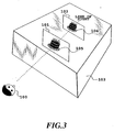
- Fig. 3 and Figs. 10A and 10B are schematic views for explaining the principle of a three-dimensional display according to a first embodiment of the present invention.
- a plurality of planes such as planes 101, 102 (plane 101 is closer to the observer 100 than plane 102) are provided in front of an observer 100.
- an optical system 103 is constructed by using two-dimensional displays and a variety of optical elements (details will be given later).
- Examples of the two-dimensional displays may include CRT, liquid crystal display, LED display, plasma display, FED display; projection type display and line drawing type display, and examples of the optical elements may include lens, total reflecting mirror, partial reflecting mirror, curved mirror, prism, polarizer and wavelength plate.
- a three-dimensional object 104 which is to be presented to the observer 100, is projected onto the planes 101, 102 to generate images 105, 106 (hereinafter referred to as two-dimensional images).
- the two-dimensional images can be formed by a variety of ways, which include a technique that uses two-dimensional images formed by photographing the object 104 by camera along the line of sight; a technique that synthesizes a plurality of two-dimensional images shot from different directions; or synthesizing and modeling techniques based on computer graphics.
- these two-dimensional images 105, 106 are displayed on the planes 101, 102 respectively so that they overlap each other by viewing from one point on the line of which passes through the right and left eyes of the observer 100.
- the brightness of the two-dimensional image 105 on this plane is set equal to the brightness of the three-dimensional object 104 and the brightness of the two-dimensional image 106 is set to zero, as shown in Fig. 5.
- the three-dimensional object 104 is slightly moved away from the observer 100 and is located at a position slightly away from the plane 101 and closer to the plane 102, the brightness of the two-dimensional image 105 is slightly lowered and the brightness of the two-dimensional image 106 is slightly raised, as shown in Fig. 6.
- the object 104 When for example the object 104 is moved further away from the observer 100 and is located at a position further away from the plane 101 and closer to the plane 102, the brightness of the two-dimensional image 105 is further lowered and the brightness of the two-dimensional image 106 is further raised, as shown in Fig. 7.
- the brightness of the two-dimensional image 106 is set equal to the brightness of the object 104 and the brightness of the two-dimensional image 105 is set to zero, as shown in Fig. 8.
- the observer 100 is made to feel as if the object 104 is located between the planes 101 and 102 because of observer's physiological or mental factors or optical illusion although what is actually shown to the observer is the two-dimensional images 105, 106.
- the object 104 looks as if it lies near to a middle point between the depth positions of the planes 101, 102.
- the first embodiment can apparently be used as a method and apparatus for showing the depth of a three-dimensional object itself.
- the outline configuration of a three-dimensional display according to this embodiment is as shown in Fig. 3, in which a plurality of planes, for example planes 101, 102 (plane 101 is closer to an observer 100 than plane 102), are set in front of the observer 100 and in which an optical system 103 is constructed by using, for example, two-dimensional displays and a variety of optical elements to display a plurality of two-dimensional images on these planes (details will be given in third and subsequent embodiments).
- the three-dimensional object 104 to be presented to the observer 100 is shot in the direction of the line of sight of both eyes of the observer 100 to generate, for instance, two-dimensional images 105, 106.
- These two-dimensional images 105, 106 are, as shown in Fig. 3, displayed on the planes 101 and 102 respectively such that they overlap each other by viewing from the point on the line of which passes through the right and left eyes of the observer.
- Position setting of each image and enlargement/reduction are executed by a computer connected with the two-dimensional display apparatus.
- Fig. 9A represents an example image displayed on a plane close to the observer 100, for example, on the plane 101
- Fig. 9B represents an example image displayed on a plane remote from the observer 100, for example, on the plane 102.
- Figs. 9A and 9B that show a cake as an object, upper and lower surfaces of the cake (object) are almost flat, except for the candles stuck on the top, the wall surface is cylindrical, and the candles are arranged near the circumference of the upper surface of the cake.
- the upper parts represent the remote parts of the cake.
- the central part of the wall surface corresponds to the near side of the cake, and as you go from the center toward the left and right, the surface position moves toward the far side.
- the central part of the hidden wall surface which is shown higher than the front wall surface, is located on the far side.
- the brightness on the upper and lower surfaces is progressively changed according to the depth position so that, as shown in Fig. 9A, on a plane close to the observer 100, or the plane 101, a portion close to the observer 100 (a lower part of the two-dimensional image) has a higher brightness level and a portion remote from the observer (an upper part of the two-dimensional image) has a lower brightness level.
- the brightness is progressively changed according to the depth position so that, as shown in Fig. 9B, a portion close to the observer (a lower part of the two-dimensional image) has a lower brightness level and a portion remote from the observer (an upper part of the two-dimensional image) has a higher brightness level.
- the brightness of the cylindrical portion is also changed progressively according to its depth position so that, on a plane close to the observer 100, or the plane 101, a portion close to the observer 100 (around the center) has a higher brightness level and a portion remote from the observer (the near left and right end) has a lower brightness level, as shown in Fig. 9A.
- the brightness is changed progressively so that, as shown in Fig. 9B, a portion close to the observer 100 (around the center) has a lower brightness level and a portion remote from the observer (the near left and right end) has a higher brightness level.
- the observer 100 is made to feel as if there is a cylindrical cake with almost flat top and bottom surfaces because of observer's physiological or mental factors or optical illusion although what is actually shown to the observer is two-dimensional images.
- Fig. 10A the brightness of the floor is gradually lowered toward the upper part of the Figure to make one feel as if the floor shown at the upper part of the Figure lies remote from the viewer in the depth direction.
- Fig. 10B the brightness of a chain (circular objects), in addition to the floor, is also lowered progressively toward the left to produce an effect that makes one perceive that the chain on the left side is far in the depth direction.
- the two-dimensional image plane in the embodiment 1 does not have to be a flat plane and can take other forms such as spherical, ellipsoidal or quadratic surfaces, or other complex curved surfaces and produce the similar effect.
- the depth distances of a plurality of the planes being within the range wherein blurring of the images obtained when the focus point is adjusted at the position of the object to be displayed on the depth direction by viewing from the observer is less is less than one obtained when the focus points are adjusted at the plurality of the planes.
- the embodiment 1 can also show an object present between a plurality of planes, it offers the advantage of being able to reduce the amount of data greatly when performing a three-dimensional display.
- the embodiment 1 takes advantage of human physiological or mental factors or optical illusion based only on brightness changes of images, the embodiment.does not require the use of a coherent light source such as a laser and facilitates the color stereoscopic image representation.
- this invention does not include mechanical driving parts, it can suitably reduce the weight of and improve the reliability of the apparatus.
- the embodiment 1 mainly concerns a case where there are only two planes for displaying two-dimensional images and where an object to be presented to the observer lies between the two planes. It is, however, apparent that the similar configuration can be employed if there are more planes or the object to be presented is located at a different position.
- a three-dimensional video image can be displayed by successively changing two-dimensional images.
- the center point between the right and left eyes of the observer is used as the above one point, it is easy to obtain the above effect and has a merit that a size of double images in the right and left eyes generated by planes 01 and 02 becomes smaller.
- Figs. 11 to 16 illustrate the principle of a three-dimensional display according to a second embodiment of the present invention.
- a plurality of planes such as planes 111 and 112 (plane 111 is closer to an observer 110 than plane 112), are installed in front of the observer 110 and, to display a plurality of two-dimensional images on these planes, an optical system 113 is constructed by using two-dimensional displays and various optical elements.
- CTR liquid crystal display
- LED display liquid crystal display
- plasma display plasma display
- FED display projection type display
- line drawing type display line drawing type display.
- optical elements may include lens, total reflecting mirror, partial reflecting mirror, curved mirror, prism, polarizer and wavelength plate.
- a three-dimensional object 114 which is to be presented to the observer 110, is projected onto the planes 111, 112 to generate images 115, 116 (two-dimensional images).
- the two-dimensional images 115, 116 can be formed by a variety of ways, which include a technique that uses two-dimensional images formed by photographing the object 114 by camera along the line of sight; a technique that synthesizes a plurality of two-dimensional images shot from different directions; or synthesizing and modeling techniques based on computer graphics.
- the two-dimensional images 115, 116 are displayed on the planes 111 and 112 respectively so that they overlap each other on the line of sight of the observer (this can be achieved by locating the centers or gravity centers of the two-dimensional images 115, 116 on the line of sight).
- each image 115, 116 is changed according to a change over time of the depth position of the three-dimensional object 114 while keeping constant the overall brightness as seen by the observer 110.
- the brightness of the two-dimensional image 115 on the plane 111 is set equal to that of the three-dimensional object 114 and the brightness of the two-dimensional image 116 on the plane 112 is set to zero.
- the brightness of the two-dimensional image 115 is lowered slightly over time according to the movement in the depth position of the three-dimensional object 114 and at the same time the brightness of the two-dimensional image 116 is slightly raised over time.
- the brightness of the two-dimensional image 115 is lowered further over time according to the movement in the depth position of the three-dimensional object 114 and at the same time the brightness of the two-dimensional image 116 is raised further over time.
- the three-dimensional object 114 When, as shown in Fig. 16, the three-dimensional object 114 finally reaches the plane 112 over time, the brightness of the two-dimensional image 116 on the plane 112 is changed over time until it becomes equal to the brightness of the three-dimensional object 114 according to the movement in the depth position of the three-dimensional object 114 and at the same time the brightness of the two-dimensional image 115 on the plane 111 is changed over time until it becomes zero.
- the observer 110 is made to feel as if the three-dimensional object 114 moves over time from the plane 111 to the plane 112 in the direction of depth because of observer's physiological or mental factors or optical illusion although what is actually shown to the observer is two-dimensional images 115, 116.
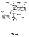
- Figs. 17A and 17B illustrate the outline configuration of a three-dimensional display according to a third embodiment of the invention.
- an image plane 2a05 and an image plane 2a06 are placed at different positions in the direction of depth, the image plane 2a05 being formed by reflecting the displayed image of the two-dimensional display 2a01 by the total reflecting mirror 2a03 and passing it through the partial reflecting mirror 2a04, the image plane 2a06 being formed by reflecting the displayed image of the two-dimensional display 2a02 by the partial reflecting mirror 2a04.
- This optical system uses only mirrors and thus has the advantage of less degradation of picture quality.
- the two-dimensional displays 2a01, 2a02 may use CRT, liquid crystal display, LED display, plasma display, FED display, DMD display, projection type display and line drawing type display.
- the image plane 2a05 which is formed by passing the displayed image of the two-dimensional display 2a01 through the partial reflecting mirror 2a04
- the image plane 2a06 which is formed by reflecting the displayed image of the two-dimensional display 2a02 by the partial reflecting mirror 2a04, can be located at different positions in the direction of depth.
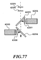
- FIG. 18A and 18B One example which can change the position of the image plane more flexibly by incorporating lens or the like in the optical system is shown in Figs. 18A and 18B.
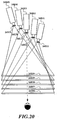
- Fig. 19 shows an example that uses an increased number of two-dimensional displays.
- 2c09 e.g., reflectivity/
- an image plane 2c11 and image planes 2c12-2c15 are placed at different positions in the direction of depth, the image plane 2c11 being formed by reflecting the displayed image of the two-dimensional display 2c01 by the total reflecting mirror 2c06 and passing it through the partial reflecting mirrors 2c07-2c10, the image planes 2c12-2c15 being formed by reflecting the displayed images of the two-dimensional displays 2c02-2c05 by the partial reflecting mirrors 2c07-2c10 and passing them through the partial reflecting mirrors.
- This optical system uses only mirrors and thus has the advantage of less degradation of picture quality.
- Fig. 20 shows one example of an optical system for arranging a plurality of two-dimensional images which is constructed by using a plurality of projection type two-dimensional displays (for example, CRT type, LCD type, ILV type and DMD type) 2d01, 2d02, 2d03, 2d04, 2d05 and scatter plates 2d06, 2d07, 2d08, 2d09, 2d10 and by projecting images from the projectors onto the scatter plates.
- projection type two-dimensional displays for example, CRT type, LCD type, ILV type and DMD type
- the scatter plates 2d06-2d10 may be such devices as can control scattering/transmission or reflection/transmission, such as polymer dispersed liquid crystal devices, holographic polymer dispersed liquid crystal devices or combined devices of liquid crystal and multi-lens array.
- Shutters 2d11-2d15 may be such devices as can control transmission/interruption, such as twisted nematic liquid crystal devices, ferroelectric liquid crystal devices or mechanical shutter devices.
- the scatter plates 2d06-2d10 are arranged at different depth positions, the focusing planes of the projector type two-dimensional displays 2d01-2d05 are aligned with these scatter plates 2d06-2d10, images are projected onto the scatter plates, and the scattering/transmission timing of the scatter plates 2d06-2d10 is synchronized with the transmission/interruption timing of the shutters 2d11-2d15 when activating the scatter plates and the shutters. This enables the depth positions of the image planes 2d11-2d15 formed on the scatter plates 2d06-2d10 to be controlled on a time division basis.
- lamps of projectors can be turned on or off instead of using the shutters.
- the third embodiment mainly concerns a case where the image planes are located near, within or beyond the three-dimensional display, these image planes can easily be located away from or in front of the three-dimensional display.
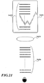
- One such example is shown in Fig. 21.
- the internal image planes 3e02 can be moved to the positions of external image planes 3e04.
- the fourth embodiment of the present invention is an example in which the optical system in the previous embodiments 1, 2 for arranging a plurality of two-dimensional images is constructed by using a volumetric three-dimensional display.
- the volumetric three-dimensional display performs three-dimensional image presentation by stacking two-dimensional images (same as the two-dimensional images in the embodiment 1) sampled in the direction of depth.
- the volumetric three-dimensional display includes a varifocal mirror type and a vibration screen type.
- the varifocal mirror type transmits an image displayed on the two-dimensional 204 such as television through a half mirror 201 and a varifocal mirror 202 to form a three-dimensional image (virtual image) for an observer 100.
- the varifocal mirror 202 is made by applying metal such as aluminum or multilayer dielectric on the surface of a woofer (low tone reproducing speaker) to form a concave mirror.
- metal such as aluminum or multilayer dielectric
- the concave mirror portion changes its curvature to change the focal length.
- the position of a virtual image or a real image of the two-dimensional display 204 can be changed by changing the focal length.
- this invention can provide a plurality of two-dimensional images by repeating a short-duration activation of the two-dimensional display a number of times.
- the depth position of an image plane can be specified by the vibration position of the varifocal mirror 202.
- this method also has an advantage of being able to form a plurality of image planes easily.
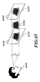
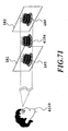
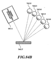
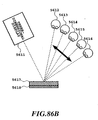
- the vibration screen type volumetric three-dimensional display includes: a vibration screen (e.g., diffusion plate, lenticular plate and fly's eye lens) 301 that vibrates in the direction of depth; an optical system 302 including lens; a scanner for raster scanning a laser beam in horizontal and vertical directions (horizontal/vertical scanner comprising, for example, a light deflector using a polygon mirror and a galvanometer mirror) 303; and a laser light source 304.
- a vibration screen e.g., diffusion plate, lenticular plate and fly's eye lens
- an optical system 302 including lens
- a scanner for raster scanning a laser beam in horizontal and vertical directions horizontal/vertical scanner comprising, for example, a light deflector using a polygon mirror and a galvanometer mirror
- a laser light source 304 e.g., a laser light source
- This method drives the scanner 303 at high speed when the vibration screen 301 is at a desired depth position, writes a sampled image corresponding to that depth position on the screen, and repeats this process by changing the depth position within the after image time, thereby reproducing a three-dimensional image.
- this embodiment can present a plurality of two-dimensional image planes by repeating within the after image time a process of writing the sample image on the vibration screen 301 at high speed.
- the depth position of the image plane can be specified by the position of the vibration screen 301.
- This method has the advantages of being able to easily suppress distortions on the screen surface and easily form a plurality of image planes.
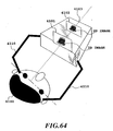
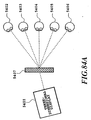
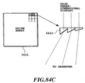
- the fifth embodiment of the present invention is a rotary LED type three-dimensional display, which, as shown in Fig. 24, includes an LED display 401 having an LED array, a rotating device 402 for rotating the LED display 401, and a video supply device 403 for feeding a video signal to the LED display 401.
- This method requires sampling a three-dimensional object in polar coordinates with the rotating axis of the LED display 401 as a center.
- the two-dimensional image sampled in the polar coordinates is displayed on the LED display 401 in synchronism with the rotation of the LED display 401 and this process is repeated by changing the rotation angle to represent a three-dimensional image.
- this embodiment can present a plurality of two-dimensional image planes by converting a desired two-dimensional image plane into the polar coordinates, displaying at high speed an image on LEDs at the converted position coordinates within the after image time, and repeating this process while changing the rotation angle.
- This method offers the advantages of being able to easily suppress distortions on the screen surface, rotate the LED display 401 relatively easily, and easily form a plurality of image planes.
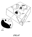
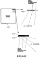
- the sixth embodiment of the present invention is a synthalyzer type three-dimensional display which, as shown in Fig. 25, includes a film recorded with two-dimensional images or a two-dimensional display (e.g., CRT and liquid crystal display) 501, a conversion optical system such as prism and mirror 502, and a projection drum 503.
- a two-dimensional display e.g., CRT and liquid crystal display
- a conversion optical system such as prism and mirror 502
- Denoted 504 is a light source and 505 a shutter.
- the projection drum 503, a key device in this method is made of a transparent material (e.g., glass and acrylics or other transparent plastics) and has a varying thickness.
- the image of the film or two-dimensional display 501 is projected through the projection drum to display an image.
- This method utilizes the fact that as the projection drum 503 is rotated, the drum thickness changes causing the position of the image plane to change.
- this embodiment can present a plurality of two-dimensional image planes by repeating the short-duration displaying of the film or two-dimensional display a number of times within the after image time.
- the depth position of the image plane can be specified by the thickness of the projection drum.
- this method has the advantage of being able to form a plurality of image planes easily.
- Figs. 26A and 26B show a conceptual diagram showing the outline configuration of a three-dimensional display according to this embodiment.
- Figs. 26A and 26B show a conceptual diagram showing the outline configuration of a three-dimensional display according to this embodiment.
- components of the three-dimensional display of this embodiment that are identical with the corresponding components of the preceding embodiments 1 to 6, detailed explanations of their constructions and operations are omitted.
- a two-dimensional image with depth information which was generated by a two-dimensional image generation device 1102 is distributed into a plurality of images (in this case, five images) for different depth positions by a distributor 1103.
- the brightness for each of the distributed two-dimensional images with depth information is changed by a brightness change device 1104 according to the depth position of the image.
- the display elements are moved by a position change device (two-dimensional image change device) 1105 to such positions that the axes of the images as seen from an observer overlap each other, and the brightness changed images are displayed on the two-dimensional displays 1106-1110, thus providing a three-dimensional representation.
- Fig. 27 is a conceptual diagram showing the working of the distributor 1103.
- An image 1207 to be represented between an image plane 1202 and an image plane 1203 is displayed on the image plane 1202 and the image plane 1203.
- An image 1208 to be represented between image planes 1203 and 1204 is displayed on the image planes 1203 and 1204.
- Images to be represented between image planes 1204 and 1205 and between image planes 1205 and 1206 are displayed in the similar way.
- the image to be represented (for example, image 1207) may be located at any position between the image planes 1202 and 1203.
- a part to be shown in front of the image plane 1204 is displayed in the same way as the front image 1208 and a part to be shown behind the image plane 1204 is displayed in the same way as the rear image 1210.
- a two-dimensional image with depth information which was generated by a two-dimensional image generation device 1122 is distributed into a plurality of images (in this case, five images) for different depth positions by a distributor 1123.
- the brightness for each of the distributed two-dimensional images with depth information is changed by a brightness change device 1124 according to the depth position of the image.
- Displays 1126-1130 are moved by a position change device (two-dimensional image change device) 1125 to such positions that the axes of the images as seen from an observer overlap each other, and the brightness changed images are displayed on these displays 1126-1130 thus providing a three-dimensional representation.
- Figs. 28A to 28C are conceptual diagrams showing how an image moves, according to this embodiment.
- Fig. 28A shows a conceptual diagram for a case where a three-dimensional image is reproduced at around an intermediate part between two image planes 1301 and 1302.
- the images displayed on the front and rear image planes are located at images 1306 and 1309.
- the image 1306 is moved to a position of an image 1307 and the image 1309 to a position of an image 1311 because the reproducing position of the three-dimensional image 312 must be fixed.
- the images are moved to positions of images 1308 and 1310 respectively.
- Fig. 28B is a conceptual diagram for a case where a three-dimensional image 1313 is reproduced between two image planes 1321 and 1322 at a position close to the image plane 1322.
- the images displayed on the front and rear image planes are located at images 1326 and 1329.
- the image 1326 When the viewing point of the observer 1323 moves to a viewing position of an observer 1324, the image 1326 is moved to a position of an image 1327 and the image 1329 is left almost at its position because the reproducing position of the three-dimensional image 1313 needs to be fixed. When the viewing point moves to a viewing position of an observer 1325, the image 1326 is moved to a position of an image 1328.
- Fig. 28C is a conceptual diagram for a case where a three-dimensional image 1314 is reproduced between two image planes 1331 and 1332 at a position close to the image plane 1331.
- the images displayed on the front and rear image planes are located at images 1336, 1337.
- the image 1337 is moved to a position of an image 1339 and the image 1336 is left almost at its position because the reproducing position of the three-dimensional image 1314 needs to be fixed.
- the image 1337 is moved to a position of an image 1338.
- Figs. 29A and 29B are conceptual diagrams showing how the display elements are moved.
- One method of moving an image is, as shown in Figs. 29A and 29B, to move an image 1403 displayed on a two-dimensional display 401 vertically or horizontally, or to enlarge or reduce an image 1413 displayed on a two-dimensional display 411, or to combine these methods and electrically rewrite the display element.
- a Figure needs to be deformed slightly (as by trapezoidal deformation) as when an observer moves greatly, the display element on the display is also changed at the same time.
- the amount of movement of the image is small, such a change is not necessary as long as the displayed object looks natural to the observer.
- the displayed image is rewritten into an image as it will appear when viewed from the observer, thus producing a movement parallax, too.
- the displayed image is rewritten into an image as it will appear when viewed from the left viewing point corresponding to the position of the observer.
- the required movement parallax can be realized.
- the corresponding movement parallax is produced by the similar method.
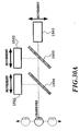
- the mechanical moving method includes: moving two-dimensional displays 1501, 1502, 1503 (Fig. 30A); in a three-dimensional display having half mirrors, rotating the half mirrors 1514, 1515 (Fig. 30B); and moving an entire three-dimensional display 1601 (Fig. 31).
- the display element on the display is also changed at the same time or corrections are made on an optical system such as prism.
- the optical system for corrections may include one of a prism, a lens and parallel plates, or a combination of these.
- the display element moving method As a further image moving method, it is possible to combine the display element moving method with the mechanical moving method. In this method, to follow a large movement of an observer, the image is moved by the mechanical moving method to expand the viewing zone. To follow a small movement of an observer, the display element is moved. This combined method can simplify the moving apparatus, prevent the observer from feeling incongruous, and ensure swift movement of images.
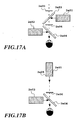
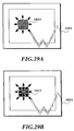
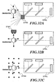
- the movement of an observer may preferably be detected by determining the position of the observer relative to a three-dimensional display 701 by using an infrared sensor 1702 as shown in Fig. 32A, an ultrasonic distance sensor or laser distance sensor 1703 as shown in Fig. 32B and an optical sensor as shown in Fig. 32C.
- publicly known technologies may be used.
- Other known technologies may also be used, which include a method that detects the position of an observer from the image provided by a camera 1805 as shown in Fig. 33A and a method that uses a magnetic sensor 1-807 possessed by an observer or a magnetic sensor 1806 installed in the three-dimensional display to detect the position of an observer.
- Fig. 34 is a block diagram showing a concept of a three-dimensional display according to this invention.
- the three-dimensional representation method of this embodiment too, has a plurality of image planes (display surfaces), for example image planes 2102, 2103, set in front of an observer 2101, as shown in Fig. 34, and a plurality of two-dimensional images are displayed on these image planes by using two-dimensional displays and an optical system.
- image planes display surfaces
- image planes 2102, 2103 set in front of an observer 2101, as shown in Fig. 34
- a three-dimensional object to be presented to the observer 2101 is projected onto the image planes 2102, 2103 along the line of sight of both eyes of the observer to generate two-dimensional images.
- the two-dimensional images can be generated by a variety of methods, which include one that uses two-dimensional images of the object shot by camera from the line of sight, one that synthesizes a plurality of two-dimensional images shot from different directions, and one that uses a synthesizing technique or modeling technique based on computer graphics.
- an image generator 2105 when an object to be presented is a plurality of objects located at different depth positions and overlapping each other on the line of sight of the observer 2101, an image generator 2105 generates for each of the objects to be presented two-dimensional images that are to be displayed simultaneously on a plurality of image planes, e.g., the image planes 2102, 2103.
- each object to be displayed there are generated two-dimensional images which are projected from the object onto the image planes 2102, 2103 from the line of sight of both eyes of the observer 2101.
- two-dimensional images to be displayed at desired depth positions are generated by the image generator 2105 shown in Fig. 34 in the order from the near depth position to the far depth position with respect to the observer, in the reverse order or in a random order.
- the brightness of the generated two-dimensional images to be displayed on the image planes 2102, 2103 is changed by a brightness change device 2104 to the brightness values corresponding to their depth positions, and the two-dimensional images thus generated are displayed on the image planes 2102, 2103.
- a synchronizer 2106 synchronizes the depth positions for which the image generator 2105 generates the images with the depth positions for which the synchronizer 2106 changes the brightness of the images. That is, the images and their corresponding depth positions are synchronized.
- the synchronizer 2106 shown in Fig. 34 is conceptually illustrated, and the brightness can be changed either mechanically or by software. Two or more synchronizers 2106 may be used.
- the brightness change device 2104 and the synchronizer 2106 may be constructed as one device.
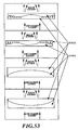
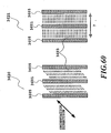
- Step 2000 Two-dimensional images of an object that one wants reproduced at a front position as viewed from an observer, such as a three-dimensional image 2204, are changed in brightness by the brightness change device 2104 and the synchronizer 2106 and then displayed on image planes 2202, 2203 to reproduce the three-dimensional image 2204.
- Step 2001 Next, two-dimensional images of an object that one wants reproduced at an intermediate position as viewed from an observer, such as a three-dimensional image 2214, are changed in brightness and displayed on image planes 2212, 2213 to reproduce the three-dimensional image 2214.
- Step 2003 Next, two-dimensional images of an object that one wants reproduced at a rear position as viewed from an observer, such as a three-dimensional image 2224, are changed in brightness and displayed on image planes 2222, 2223 to reproduce the three-dimensional image 2224.
- Changing the brightness can be achieved by two methods: one is to change the brightness according to the three-dimensional image to be displayed and then display the image, and one is to change the brightness continuously while displaying the three-dimensional image.
- the brightness of the front image plane may be changed from high to middle to low and the brightness of the rear image plane from low to middle to high so that the overall brightness as seen by the observer remains constant in order to change the position at which the three-dimensional image is reproduced from the front toward the rear. It is possible to reverse the brightness changing order.
- Another method is to change the brightness freely according to any desired position where a three-dimensional image is to be reproduced.
- This embodiment greatly differs from conventional techniques in that the steps 2000, 2001 and 2002 in Fig. 35 are repeated at high speed during the display of image.
- the speed at which the steps 2000, 2001 and 2002 of Fig. 5 are repeated is set within the after image time of human eye, for example at 60 Hz or higher, to realize displaying of a three-dimensional image without flicker.
- displaying two or more overlapping three-dimensional images can be achieved by performing the image displaying procedures on a time division basis at high speed such that the resultant images are all displayed sequentially within the after image time of human eye.
- the number of brightness-changed two-dimensional images for different depth positions needs to be greater than the maximum number of brightness-changed images required to display the overlapping portions of the three-dimensional images.
- Fig. 36 is a schematic diagram showing the outline configuration of a three-dimensional display according to an eighth embodiment of the invention.
- two-dimensional displays 2304, 2305 define the front and rear image planes respectively and the two-dimensional images displayed on the two image planes are arranged on the same optical axis by half mirrors 2302, 2303.
- the images displayed on the two-dimensional displays 2304, 2305 are, as shown in Fig. 35, rapidly changed in brightness and displayed to the observer 2301 repetitively.
- the two-dimensional displays 2304, 2305 may use CRT, liquid crystal display and plasma display and, when higher speed is required, can use displays using ferroelectric liquid crystals or antiferroelectric liquid crystals.
- a display that allows high-speed random access to individual pixels, such as a display of oscilloscope.
- the brightness levels of two-dimensional images displayed on the two-dimensional displays 2304, 2305 are changed by the two-dimensional displays 2304, 2305 themselves.
- Fig. 37 is a schematic diagram showing the outline configuration of a three-dimensional display according to a ninth embodiment of the present invention.
- Reference number 2401 represents an observer, 2402 and 2403 half mirrors, and 2404 and 2405 two-dimensional displays.
- the three-dimensional display of this embodiment differs from the three-dimensional display of the eighth embodiment in that the brightness of displayed images are changed by beam attenuating filters 2406, 2407.
- the beam attenuating filters 2406, 2407 may be a filter that continuously changes its light intensity attenuation by mechanical rotation, a filter that electrically attenuates light intensity by liquid crystals, a device that has slits having changing opening areas and arranged in the direction of rotation and which mechanically rotates the slits to change the brightness, and a device which changes the opening time by a ferroelectric shutter to change the brightness.
- the attenuation of the beam attenuating filters 2406, 2407 is synchronized with the two-dimensional images displayed on the two-dimensional displays 2404, 2405 to display a three-dimensional image.
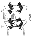
- Fig. 38 is a schematic diagram showing the outline configuration of a three-dimensional display according to a tenth embodiment of the invention.
- Reference number 2501 represents an observer, 2502 and 2503 half mirrors, 2504 and 2505 screens, 2506-2511 two-dimensional displays, and 2512-2517 shutters.
- a plurality of projector type two-dimensional displays 2506-2511 are used.
- a two-dimensional display 2506 displays a two-dimensional image for a front three-dimensional image as viewed from an observer
- a two-dimensional display 2507 displays a two-dimensional image for an intermediate three-dimensional image
- a two-dimensional display 2508 displays a two-dimensional image for a rear three-dimensional image.
- Shutters 2512-2514 are operated to project these two-dimensional images sequentially on a time division basis onto a screen 2504.
- a two-dimensional display 2509 displays a two-dimensional image for a front three-dimensional image as viewed from an observer
- a two-dimensional display 2510 displays a two-dimensional image for an intermediate three-dimensional image
- a two-dimensional display 2511 displays a two-dimensional image for a rear three-dimensional image.
- Shutters 2515-2517 are operated to project these two-dimensional images sequentially on a time division basis onto a screen 2505.
- the two-dimensional images displayed on the screens 2504, 2505 are arranged on the same optical axis by half mirrors 2502, 2053.
- the brightness of each of the two-dimensional images projected from the two-dimensional displays 2506-2511 is preset to a desired brightness level corresponding to the depth position of the two-dimensional image displayed.
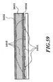
- Fig. 39 is a schematic diagram showing the outline configuration of a three-dimensional display according to a eleventh embodiment of the invention.
- Reference number 2601 represents an observer, 2602 and 2603 half mirrors, 2604 and 2605 screens, 2606-2611 two-dimensional displays, 2612-1617 shutters, and 2618-2623 beam attenuating filters.
- the three-dimensional display of this embodiment differs from the three-dimensional display of the preceding tenth embodiment in that the brightness of each of the two-dimensional images displayed on the two-dimensional displays 2606-2611 is changed by beam attenuating filters 2618-2623 installed at the front of the two-dimensional displays 2606-2611.
- the brightness of each two-dimensional display can be set constant and therefore the beam attenuating filters 2618-2623 may have fixed levels of attenuation.
- the beam attenuating filters 2618-2623 may be a filter that continuously changes its light intensity attenuation by mechanical rotation, a filter that electrically attenuates light intensity by liquid crystals, a device that has slits having changing opening areas and arranged in the direction of rotation and which mechanically rotates the slits to change the brightness, and a device which changes the opening time by a ferroelectric shutter to change the brightness.
- the attenuation of the beam attenuating filters 2618-2623 is synchronized with the two-dimensional images projected from the two-dimensional displays 2606-2611 to produce three-dimensional images.
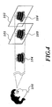
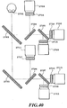
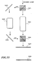
- Fig. 40 is a schematic diagram showing the outline configuration of a three-dimensional display according to a twelfth embodiment of the present invention.
- Reference numeral 2701 denotes an observer, 2702-2707 half mirrors, 2708-2713 two-dimensional displays, and 2714-2719 shutters.
- the light axes of the two-dimensional displays 2708-2710 are aligned with each other by the half mirrors 2704, 2705, and the two-dimensional images displayed on the two-dimensional displays 2708-2710 are projected onto the front image plane by the shutters 2714-2716 on a time division basis.
- the light axes of the two-dimensional displays 2711-2713 are aligned with each other by the half mirrors 2706, 2707, and the two-dimensional images displayed on the two-dimensional displays 2711-2713 are projected onto the rear image plane by the shutters 2717-2719 on a time division basis.
- a CRT For the two-dimensional displays 2708-2713, a CRT, a liquid crystal display and a plasma display may be used. When a faster speed is required, a display using ferroelectric liquid crystals or antiferroelectric liquid crystals may be used.
- a display that allows high-speed random access to individual pixels, such as a display of oscilloscope.
- the brightness levels of two-dimensional images displayed on the two-dimensional displays 2708-2713 are changed by the two-dimensional displays 2708-2713 themselves.
- Fig. 41 is a schematic diagram showing the outline configuration of a three-dimensional display according to a thirteenth embodiment of the invention.
- Reference number 2801 denotes an observer, 2802-2807 half mirrors, 2808-2813 two-dimensional displays, 2714-2719 shutters and 2720-2725 beam attenuating filters.
- the three-dimensional display of this embodiment differs from the three-dimensional display of the preceding twelfth embodiment in that the brightness of each of the two-dimensional images displayed on the two-dimensional displays 2808-2813 is changed by the beam attenuating filters 2720-2725 disposed at the front of the two-dimensional displays 2808-2813.
- the brightness of each two-dimensional display can be set constant and therefore the beam attenuating filters 2720-2725 can use fixed levels of attenuation.
- the beam attenuating filters 2720-2725 may be a filter that continuously changes its light intensity attenuation by mechanical rotation, a filter that electrically attenuates light intensity by liquid crystals, a device that has slits having changing opening areas and arranged in the direction of rotation and which mechanically rotates the slits to change the brightness, and a device which changes the opening time by a ferroelectric shutter to change the brightness.
- the attenuation of the beam attenuating filters 2720-2725 is synchronized with the two-dimensional images projected from the two-dimensional displays 2808-2813 to produce three-dimensional images.
- a plurality of objects which have different depth positions and overlap each other on the line of sight of an observer can be represented by three-dimensional images in such a way that all the three-dimensional images can be seen by the observer without being hidden by the front images.
- the three-dimensional display according to a fourteenth embodiment of the present invention represent the overall depth position of the entire three-dimensional object between a plurality of image focusing planes.
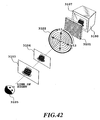
- Fig. 42 shows the outline configuration of the three-dimensional display of the fourteenth embodiment of the invention.
- This three-dimensional display includes a two-dimensional display 3100, a polarization varying device 3101 and a polarization type bifocal optical system 3102.
- the display light of a two-dimensional image displayed on the two-dimensional display 3100 is split and displayed onto two image focusing planes (in Fig. 42, image focusing planes 3103 and 3104) of the polarization type bifocal optical system 3102 at a brightness ratio that depends on a polarization direction of exit light from the polarization varying device 3101.
- the two-dimensional image displayed on the two-dimensional display 3100 is focused on, for example, the image focusing plane 3103.
- the polarization direction of the exit light matches the other intrinsic polarization direction P12, the two-dimensional image displayed on the two-dimensional display 3100 is focused on the image focusing plane 3104.
- the brightness levels of the image focusing planes 3103 and 3104 are set according to a ratio of components of the exit light polarization direction as projected onto the orthogonal intrinsic polarization directions.
- the two-dimensional displays 3100 are a CRT display, a liquid crystal display, an LED display, a plasma display, an FED display, a projection type display and a line drawing type display.
- An example of the polarization varying device 3101 includes a device using liquid crystals and a device using PLZT which has birefringence and can control the birefringence by an electric field. These devices will be described later.
- an example of the polarization type bifocal optical system 3102 includes a device using liquid crystals and a device which has two optical systems with image focusing planes different from those of the polarization beam splitter or two optical systems with image focusing planes different from those of the beam splitter and the polarizer. These devices will be described later.
- a three-dimensional object 3106 to be presented to an observer 3105 is projected along the line of sight of both eyes of the observer 3105 onto image focusing planes 3-103, 3104 to form two-dimensional images 3107, which are then displayed on the two-dimensional displays 3100 shown in Fig. 42.
- the two-dimensional images 3107 may be generated in a variety of ways, which include a method that uses two-dimensional images of the three-dimensional object 3106 shot by camera from the direction of line of sight; a method that synthesizes a plurality of two-dimensional images shot from different directions; or a method that uses synthesizing and modeling techniques based on computer graphics.
- Each polarization varying element of the polarization varying device 3101 is related to one or more groups of pixels on the two-dimensional display 3100.
- one pixel 3110 of the two-dimensional display 3100 is related to one polarization varying element 3111 of the polarization varying device 3101.
- a plurality of pixels 120 of the two-dimensional display 3100 are related to one polarization varying element 3121 of the polarization varying device 3101.
- the exit light polarization direction of the polarization varying element (for example, 3111 of Fig. 44 or 3121 of Fig. 45) of the polarization varying device 3101 is changed according to the depth position of that part of the three-dimensional object 3106 which corresponds to the associated pixel (e.g., 3110 in Fig. 44) or pixels (e.g., 3120 in Fig. 45) of the two-dimensional display 3100.
- the exit light polarization direction of the polarization varying element (for example, 3111 of Fig. 44 or 3121 of Fig. 45) of the polarization varying device 3101 is changed according to the depth position of that part of the three-dimensional object 3106 which corresponds to the associated pixel (e.g., 3110 in Fig. 44) or pixels (e.g., 3120 in Fig. 45) of the two-dimensional display 3100.
- the positional relation of the image focusing planes 3103, 3104 is adjusted in advance by using an appropriate optical system so that the images on the image focusing planes 3103, 3104 overlap each other on the line of sight of the observer 3105.
- Overlapping the images of the image focusing planes 3103, 3104 on the line of sight of the observer 3105 can be realized by putting the centers or gravity centers of the two-dimensional images 3107 on the line of sight.
- the essential point of the three-dimensional display of this embodiment is that, by changing the exit light polarization direction of each polarization varying element of the polarization varying device 3101, the brightness of each part of the images on the image focusing planes 3103, 3104 is changed according to the depth position of the three-dimensional object 3106 while keeping constant the overall brightness as seen by the observer 3105.
- the image focusing plane 3103 is located closer to the observer 3105 than the image focusing plane 3104 and that the intrinsic polarization directions of the polarization type bifocal optical system 3102 for the image focusing planes 3103, 3104 are taken as p11 and p12.
- the observer 3105 perceives the three-dimensional object 3106 to be located between the image focusing planes 3103 and 3104 because of observer's physiological or mental factors or optical illusion although the images are actually displayed on the image focusing planes 3103, 3104.
- the three-dimensional display of this embodiment has at least two image displaying planes on the near and far sides of the optical illusion position, it is possible to suppress contradictions among the binocular parallax, convergence and focusing -- the problem experienced with the conventional three-dimensional displaywhich in turn is expected to reduce eyestrains.
- this embodiment has the advantage of being able to provide a realistic three-dimensional image representation, not the kind of conventional solidity presented by gathering sheet-divided depths.
- the three-dimensional display of this embodiment also has the advantage of being able to significantly reduce the amount of data required for three-dimensional representation because it can represent even a three-dimensional object disposed between a plurality of planes.
- the three-dimensional display of this embodiment utilizes human physiological or mental factors or optical illusion based on changes in image brightness, there is an advantage that a coherent light source such as a laser is not required and that a color stereoscopic image representation can be easily realized.
- the three-dimensional display of this embodiment does not include mechanical driving parts, it has the advantage of light weight and improved reliability.
- this embodiment has the advantage of simple control.
- the resolutions of images can be differentiated, the amount of information can be reduced. That is, in view of the fact that the resolution requirement for the depth direction is lower than that for the two-dimensional direction, it may be an effective method to reduce the resolution in the depth direction.
- the size of the device is not restricted by the position, interval and size of the image focusing planes.
- the image focusing planes 3103, 3104 at the front side of the three-dimensional display as virtual planes by an optical system, or at the rear side by another optical system.
- the image focusing planes 3103, 3104 can be spaced apart a greater distance than in this embodiment by an optical system.
- the size of the formed images can also be made larger than in this embodiment by an optical system.
- this embodiment has the advantage of being able to reduce the overall size of the three-dimensional display.
- the above description concerns a case where the brightness levels of the two-dimensional images 3107 on a plurality of image focusing planes 3103, 3104 are changed while keeping constant the overall brightness as seen by the observer. It is a common technique employed in computer graphics to progressively reduce the overall brightness as seen by the observer 3105 toward the far side in order to make the image look solid. It is obvious that the use of this technique also in this embodiment can further enhance the three-dimensional effect.
- Sequentially changing the two-dimensional images 3107 and the polarization direction of the display light of the two-dimensional images 3107 and throwing it onto a plurality of image focusing planes 3103, 3104 at different depth positions can generate a three-dimensional video image.
- This embodiment has described only the basic configuration and it is apparent that aberration can be reduced by adding optical systems.
- this embodiment has described a case where an observer 3105 is located at the front center of the three-dimensional display. If the observer 310 is located at other positions, it is apparent that the similar effects can easily be produced by changing or adding optical systems.
- the three-dimensional display according to a fifteenth embodiment of the invention differs from the preceding embodiment in that the three-dimensional display represents the depth of the three-dimensional object itself.
- Fig. 50 shows the outline configuration of the three-dimensional display of the fifteenth embodiment of the invention.
- the three-dimensional display includes a two-dimensional display 3200, a polarization varying device 3201 and a polarization type bifocal optical system 3202.
- the display light of a two-dimensional image displayed on the two-dimensional display 3200 is split and displayed onto two image focusing planes (in Fig. 50, image focusing planes 3203 and 3204) of the polarization type bifocal optical system 3202 at a brightness ratio that depends on a polarization direction of exit light from the polarization varying device 3201.
- the two-dimensional images 3207 of a three-dimensional object to be represented are displayed on the two-dimensional display 3200.
- each polarization varying element of the polarization varying device 3201 is related to one or more pixels of the two-dimensional display 3200.
- the exit light polarization direction of the related polarization varying element is changed according to the depth position of that part of the three-dimensional object which corresponds to the associated pixel (e.g., 3110 in Fig. 44) or pixels (e.g., 3120 in Fig. 45) of the two-dimensional display 3200.
- the associated pixel e.g., 3110 in Fig. 44
- pixels e.g., 3120 in Fig. 45
- the positional relation of the image focusing planes 3203, 3204 is adjusted in advance by using an appropriate optical system so that the images on the image focusing planes 3203, 3204 overlap each other on the line of sight of the observer 3205.
- the essential point of the three-dimensional display of this embodiment is that, by changing the exit light polarization direction of each polarization varying element of the polarization varying device 3201, the brightness of each part of the images on the image focusing planes 3203, 3204 is changed according to the depth position of each part of the three-dimensional object while keeping constant the overall brightness as seen by the observer 3205.
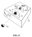
- Fig. 51A show an example image formed on an image focusing plane close to the observer, for example image focusing plane 3203
- Fig. 51B represents an example image formed on an image focusing plane remote from the observer, for example image focusing plane 3204.
- a cake as shown in Figs. 51A and 51B, is taken as an example object, the top and bottom surfaces of the cake is almost flat except for candles stuck on the top, the wall surface is cylindrical, and the candles are arranged near the circumference of the top surface of the cake.
- the upper parts represent the remote parts of the cake.
- the central part of the wall surface corresponds to the near side of the cake, and as you go from the center toward the left and right, the surface position moves toward the far side.
- the central part of the hidden wall surface which is shown higher than the front wall surface, is located on the far side.
- polarization direction of each part needs to be changed by considering the two intrinsic polarization directions of the polarization type bifocal optical system 3202 so that the brightness levels of the image focusing planes 3203, 3204 will change as follows.
- the brightness on the top and bottom surfaces is progressively changed according to the depth position so that, as shown in Fig. 51A, on an image focusing plane 3203 close to the observer 3205 a portion close to the observer 3205 (a lower part of the two-dimensional image 3207) has a higher brightness level and a portion remote from the observer (an upper part of the two-dimensional image 3207) has a lower brightness level.
- the brightness is progressively changed according to the depth position so that, as shown in Fig. 51B, a portion close to the observer 3205 (a lower part of the two-dimensional image 3207) has a lower brightness level and a portion remote from the observer (an upper part of the two-dimensional image 3207) has a higher brightness level.
- the brightness of the cylindrical portion is also changed progressively according to its depth position so that, on an image focusing plane close to the observer 3205, a portion close to the observer 3205 (around the center) has a higher brightness level and a portion remote from the observer (near the left and right end) has a lower brightness level, as shown in Fig. 51A.
- the brightness is changed progressively so that, as shown in Fig. 51B, a portion close to the observer 3205 (around the center) has a lower brightness level and a portion remote from the observer (near the left and right end) has a higher brightness level.
- the observer 3205 perceives as if there is a cylindrical cake with almost flat top and bottom surfaces because of observer's physiological or mental factors or optical illusion although what is actually shown to the observer is two-dimensional images.
- Fig. 52 shows examples of the polarization type bifocal optical system that can be used in the three-dimensional displays of the preceding embodiments.
- the polarization type bifocal optical systems represented by reference numerals 3310-3313 in Fig. 52 each have a fixed focus lens 3301 and a birefringent area 3302.
- the fixed focus lens 3301 is formed by, for example, a convex lens of glass or plastics as shown in a polarization type bifocal optical system 3313; a concave lens of glass or plastics as shown in a polarization type bifocal optical system 3312; or a lens system combining convex lens, concave lens and prism of glass or plastics or a mirror system combining convex lens, concave lens and prism as shown in polarization type bifocal optical systems 3310, 3311, respectively.
- the birefringent area 3302 is formed of, for example, a medium of liquid crystals or PLZT that has birefringence.
- the refractive index of the fixed focus lens 3301 is n1
- the intrinsic polarization directions in the birefringent area 3302 are p21 and p22
- the refractive indices in these polarization directions are n21 and n22.
- the incident light When, for example, light enters from the birefringent area 3302, the incident light is split into polarized light beams having polarization directions of p21 and p22 according to the polarized state.
- the polarized beams propagate according to the refractive indices n21, n22 they sense, and contact the fixed focus lens 3301 of the refractive index of n1.
- the two polarized light beams which remain split as they go out, form images at different positions according to the difference in the refractive index. That is, this optical system works as a bifocal optical system that splits light beam according to the polarization directions.
- the light when light enters from the fixed focus lens 3301 side, the light is split according to the refractive indices associated with the intrinsic polarization directions and forms images on two different image focusing planes.
- the addition of an alignment layer 3303 can ensure uniform in-plane splitting of light entering from the birefringent area 3302 side.
- the alignment layer 3303 is provided on only one of the birefringent areas 3302, the incident light becomes twisted by its own optical activity according to the alignment of the birefringent medium. Because the refractive indices that the split light beams sense do not change, the aforementioned effect will also be produced without problem.
- Providing an alignment layer also on the side of an interface with the fixed focus lens 3301 is effective when light is thrown in from the fixed focus lens 3301 side or when such alignment-dependent optical systems are connected in series.
- Liquid crystal are useful as a birefringent medium because of their large refractive anisotropy.
- Applicable kinds of liquid crystals include ordinary nematic liquid crystal, polymer dispersed liquid crystal, holographic polymer dispersed liquid crystal, polymer liquid crystal, smectic liquid crystal, ferroelectric liquid crystal, and polymer stabilized ferroelectric liquid crystal.
- birefringence can also be obtained with polymer materials other than liquid crystals by aligning the major axes of the polymer materials during forming.
- Fig. 55 shows other examples of the polarization type bifocal optical system that can be used in the three-dimensional displays of the preceding embodiments.
- the polarization type bifocal optical system shown in Fig. 55 comprises: a polarizing beam splitter 3401 for splitting a beam on the incoming side; two optical systems 3402, 3403 with different focal lengths; a polarizing beam splitter 3404 for synthesizing on the outgoing side; and plane mirrors 3405, 3406 for bending a light path.
- the two optical systems 3402, 3403 are formed, for example, by convex lens, concave lens, prism, convex/concave mirror or plane mirror or a combination of these.
- incident light is split by the polarizing beam splitter 3401 into two intrinsic polarized beams p41, p42 at a brightness ratio that corresponds to their polarization directions, and then fed into the optical systems 3402, 3403.
- the optical systems 3402, 3403 have different focal lengths and thus the incident polarized beams p41, p42 have different image forming distances.
- the optical system shown in Fig. 55 can form a polarization type bifocal optical system that can split light at a brightness ratio that corresponds to the polarization directions.
- Fig. 56 includes polarizing plates 3411, 3412 whose polarization directions are perpendicular to that of the beam splitter 3410 (e.g., semitransparent mirror and semitransparent prism). This configuration provides the similar effects.
- a well known example of device that can change the polarization direction of incident light, as do the polarization varying devices used in the three-dimensional displays of the preceding embodiments, is a device that uses a medium (e.g., liquid crystals and PLZT) capable of changing birefringence by electric field and voltage.
- a medium e.g., liquid crystals and PLZT
- Fig. 57 shows the outline configuration of a twisted nematic type polarization varying device that can be used in the three-dimensional displays of the preceding embodiment.
- the twisted nematic type polarization varying device shown in Fig. 57 includes a transparent conductive layer (transparent electrode) 3501, an alignment layer 3502, a nematic liquid crystal region 3503, an alignment layer 3504, and a transparent conductive layer (transparent electrode )3505.
- orientation directions of the alignment layers 3502 and 3504 are set perpendicular to each other and that a chiral material is added so that the liquid crystal molecules are twisted or describe a spiral in the same direction.
- the linearly polarized incident light therefore has its polarization direction changed almost 90 degrees by the optical activity of the liquid crystals (one of the properties of the birefringent material) before going out of the liquid crystals.
- the incident light goes out almost without changing the polarization direction.
- the polarization direction of the incident light can be changed by the voltage applied between the transparent conductive films 3501 and 3505.
- Fig. 59 shows the outline configuration of an in-plane type polarization varying device that can be used in the two-dimensional displays of the preceding embodiments.
- the in-plane type polarization varying device includes a transparent conductive film (transparent electrode) 3601, an alignment layer 3602, a nematic liquid crystal region 3603, an alignment layer 3604, and a transparent conductive film (transparent electrode) 3605.
- orientation directions of the alignment layer 3602 and the alignment layer 3604 are parallel, and the transparent conductive films 3601 and 3605 are in the same plane.
- Fig. 61 shows the outline configuration of a homogeneous type polarization varying device that can be used in the three-dimensional displays of the preceding embodiments.
- the homogeneous type polarization varying device shown in Fig. 61 includes a transparent conductive film (transparent electrode) 3611, an alignment layer 3612, a liquid crystal (e.g., nematic liquid crystal) region 3613, an alignment layer 3614, and a transparent conductive film (transparent electrode) 3615.
- the orientation directions of the alignment layers 3612 and 3614 are set equal (parallel).
- incident light which is circularly polarized or elliptically polarized is entered into the homogeneous type polarization varying device shown in Fig. 61.
- the incident light goes out with its polarization direction changed by the birefringence of the liquid crystals.
- the polarization direction of the incident light can be changed by the voltage applied between the transparent conductive films 3611 and 3615.
- Contradictions among physiological factors associated with stereoscopy can be minimized; the amount of information required can be reduced; and electrically rewritable three-dimensional videos can be reproduced.
- a word "plane” on which to put an image is used. This is similar in meaning to an image plane that is often used in optics. Means to realize such an image plane can obviously be realized by combining many optical devices, which include a variety of optical elements (e.g., lens, total reflecting mirror, partial reflecting mirror, curved mirror, prism, polarizer and wavelength plate) and two-dimensional displays (e.g., CRT, liquid crystal display, LED display, plasma display, FED display, DMD display, projection type display and line drawing type display).
- optical elements e.g., lens, total reflecting mirror, partial reflecting mirror, curved mirror, prism, polarizer and wavelength plate
- two-dimensional displays e.g., CRT, liquid crystal display, LED display, plasma display, FED display, DMD display, projection type display and line drawing type display.
- the following examples concern a case where a three-dimensional object to be presented is displayed as two-dimensional images on mainly two planes. If the number of planes is increased to more than two, the similar effect can obviously be expected.
- Fig. 64 shows the principle of a head-mounted display according to a nineteenth embodiment of the present invention.
- a plurality of planes 4101, 4102 are set in front of an observer 4100 (with the plane 4101 put closer to the observer 4100 than the plane 4102, for example).
- an optical system 4103 is constructed by using two-dimensional displays and a variety of optical elements.
- Example two-dimensional displays include CRT, liquid crystal display, LED display, plasma display, FED display, DMD display, projection type display and line drawing type display.
- Example optical elements include lens, total reflecting mirror, partial reflecting mirror, curved mirror, prism, polarizer and wavelength plate.
- the observer 4100 wears fixing means 4110 to fix relative positions of a plurality of two-dimensional images displayed on the planes 4101, 4102 with respect to left and right eyes of the observer 4100.
- a three-dimensional object 4104 to be presented to the observer 4100 is projected onto the planes 4101, 4102 as seen from one point on a line connecting the left and right eyes of the observer 4100 to form two-dimensional images 4105, 4106.
- the two-dimensional images can be generated by a variety of ways, which include a technique that photographs the object 4104 by camera from the one point described above; a technique that synthesizes a plurality of two-dimensional images photographed from different directions; or synthesizing and modeling techniques based on computer graphics.
- the two-dimensional images 4105, 4106 are displayed on the planes 4101, 4102 as shown in Fig. 64 so that they overlap each other as seen from the one point.
- the important point of this embodiment is that, on the apparatus having the above configuration, the brightness levels of the two-dimensional images are changed according to the depth position of the three-dimensional object 4104 while keeping constant the overall brightness as seen by the observer 4100 (i.e., in such a way that the overall brightness as seen by the observer 4100 is equal to the brightness of the three-dimensional object 4104).
- Figs. 66 to 69 are black and white illustrations and, for simplicity, parts with higher brightness levels are shaded darker.
- the brightness of a two-dimensional image 4105 on the plane 4102 is set equal to that of the three-dimensional object 4104 and the brightness of the two-dimensional image 4106 on the plane 4102 is set to zero, as shown in Fig. 66.
- the brightness of the two-dimensional image 4105 is slightly lowered and the brightness of the two-dimensional image 4106 is slightly raised, as shown in Fig. 67.
- the brightness of the two-dimensional image 4105 is further lowered and the brightness of the two-dimensional image 4106 is further raised.
- the brightness of the two-dimensional image 4106 on the plane 4102 is set equal to that of the three-dimensional object 4104 and the brightness of the two-dimensional image 4105 on the plane 4101 is set to zero as shown in Fig. 69 for instance.
- Displaying the object in this manner enables the observer 4100 to feel as if the three-dimensional object 4104 is located between the planes 4101 and 4102 because of observer's physiological or mental factors or optical illusion although what is actually shown to the observer is the two-dimensional images 4105, 4106.
- the three-dimensional object 4104 looks as if it lies near to a middle point between the depth positions of the planes 4101, 4102.
- the above description concerns a method and apparatus in which the overall depth position of the three-dimensional object 4104 is represented by using two-dimensional images on the planes 4101 and 4102.
- This embodiment apparently can be applied also as a method and apparatus that represents the depth of the three-dimensional object itself.
- the brightness level of each part of the two-dimensional images 4105, 4106 needs to be changed according to the depth position of each corresponding part of the three-dimensional object 4104 while keeping constant the overall brightness as seen by the observer 4100 (i.e., in such a way that the overall brightness as seen by the observer 4100 is equal to the brightness of the three-dimensional object 4104).
- the brightness of the two-dimensional image 4105 displayed on the plane 4101 close to the observer 4100 is changed progressively according to the depth position of the corresponding part of the object so that a portion close to the observer 4100 has a higher brightness level and a portion remote from the observer has a lower brightness level.
- the brightness of the two-dimensional image 4105 displayed on the plane 4102 remote from the observer 4100 is progressively changed according to the depth position of the corresponding part of the object so that a portion close to the observer has a lower brightness level and a portion remote from the observer has a higher brightness level.
- Displaying the object in this manner enables the observer 4100 to feel as if the object presented has a solid body with some depth because of observer's physiological or mental factors or optical illusion although what is actually shown to the observer is two-dimensional images.
- this embodiment has at least two image display planes on the near and far sides of the optical illusion position, so that contradictions among the binocular parallax, convergence and focusing -- the problem experienced with the conventional apparatus -- can be suppressed significantly, which in turn is expected to reduce eyestrains.
- the focus point coincides with the optical illusion position where both of the images can be seen with minimum blur.
- this embodiment can also present a three-dimensional object 4104 that exists between a plurality of planes, there is an advantage that the amount of data required for three-dimensional representation can be reduced substantially.
- this embodiment has the advantage of being able to easily display two-dimensional images according to the movement of the observer 4100 or eyes.
- the head-mounted display is basically a display that is secured to the head of the wearer
- the present invention can apparently be applied also to an apparatus that is not mounted on the head as long as the apparatus is so constructed that the positional relationship between the eyes of the observer and the plane will not be changed.
- this embodiment makes use of human physiological or mental factors or optical illusion based only on brightness changes of two-dimensional images, the embodiment does not require the use of a coherent light source such as a laser and facilitates the color stereoscopic image representation.
- this embodiment does not include mechanical driving parts, it can suitably reduce the weight of and improve the reliability of the apparatus.
- This embodiment mainly concerns a case where there are only two planes for displaying two-dimensional images and where a three-dimensional object to be presented to the observer 4100 lies between the two planes. It is, however, apparent that the similar configuration can be employed if there are more planes or the three-dimensional object 4104 to be presented is located at a different position.
- This embodiment can obviously display a video so that an observer can see the motion of an object in the horizontal and vertical directions as long as the two-dimensional displays have display speeds compatible with the video. It is also apparent that the motion of an object in the depth direction can also be presented to the observer by changing the brightness of a plurality of planes for each frame.
- the brightness of each part of the two-dimensional images 4105, 4106 is changed according to a change over time of the depth position of the three-dimensional object 4104 while keeping constant the overall brightness as seen by the observer 4100 (i.e., in such a way that the overall brightness as seen by the observer 4100 is equal to the brightness of the three-dimensional object 4104).
- the brightness of the two-dimensional image 4105 on the plane 4101 is set equal to that of the three-dimensional object 4104 and the brightness of the two-dimensional image 4106 on the plane 4102 is set to zero.
- the brightness of the two-dimensional image 4105 is lowered slightly over time according to the movement in the depth position of the three-dimensional object 4104 and at the same time the brightness of the two-dimensional image 4106 is slightly raised over time.
- the brightness of the two-dimensional image 4105 is lowered further over time according to the movement in the depth position of the three-dimensional object 4104 and at the same time the brightness of the two-dimensional image 4105 is raised further over time.
- the brightness of the two-dimensional image 4106 on the plane 4102 is changed over time until it becomes equal to the brightness of the three-dimensional object 4104 according to the movement in the depth position of the three-dimensional object 4104 and at the same time the brightness of the two-dimensional image 4105 on the plane 4101 is changed over time until it becomes zero.
- Displaying the object in this way enables the observer 4100 to feel as if the three-dimensional object 4104 moves over time from the plane 4101 to the plane 4102 in the direction of depth because of observer's physiological or mental factors or optical illusion although what is actually shown to the observer is two-dimensional images 4105, 4106.
- this embodiment has an advantage of being able to significantly reduce the amount of data required for three-dimensional representation because this embodiment can display a stereoscopic representation of a three-dimensional object lying between a plurality of planes.
- Fig. 70 illustrates the principle of a head-mounted display according to a twentieth embodiment of the invention.
- a plurality of planes for example, planes 1R1, 1R2, 1L1, 1L2 are arranged in front of the left and right eyes of the observer 4100 (the planes 1R1, 1L1 are set closer to the observer 4100 than the planes 1R2, 1L2).
- an optical system 4103 is constructed for each of the left and right eyes by using two-dimensional displays and a variety of optical elements. (Details will be described in the twenty-first and subsequent embodiments.)
- Examples of the two-dimensional displays include CRT, liquid crystal display, LED display, plasma display, FED display, projection type display and line drawing type display.
- Examples of optical elements include lens, total reflecting mirror, partial reflecting mirror, curved mirror, prism, polarizer and wavelength plate.
- the observer 4100 wears a fixing means 4110 to fix the relative positions between the plurality of two-dimensional images displayed on these planes 1R1, 1R2, 1L1, 1L2 and the left and right eyes of the observer 4100.
- a three-dimensional object 4104 to be presented to the observer 4100 is projected onto the planes 1R1, 1R2, 1L1, 1L2, as viewed from one point on a line connecting the left and right eyes of the observer 4100, to form two-dimensional images 1R5, 1R6, 1L5, 1L6.
- Fig. 71 shows the configuration for only the right eye
- the configuration for the left eye can be obtained simply by replacing the symbol R with L.
- the two-dimensional images 1R5, 1R6, 1L5, 1L6 can be generated by a variety of ways, which include a technique that uses two-dimensional images obtained by photographing the three-dimensional object 4104 by camera in the direction of line of sight; a technique that synthesizes a plurality of two-dimensional images photographed from different directions; or synthesizing and modeling techniques based on computer graphics.
- the two-dimensional images 1R5, 1R6, 1L5, 1L6, as shown in Fig. 70, are displayed on the planes 1R1, 1L1 and planes 1R2, 2L2 so that they overlap each other as seen from one point on the line. connecting the left and right eyes of the observer 4100.
- the important point of this embodiment is that, in the apparatus having the above-described configuration, the brightness of each of the two-dimensional images 1R5, 1R6, 1L5, 1L6 is changed within the after image time of the human eye according to the depth position of the three-dimensional object 4104 (see Fig. 65) while keeping constant the overall brightness as seen by the observer 4100 (i.e., in such a way that the overall brightness as seen by the observer 4100 is equal to the brightness of the three-dimensional object 4104.
- Figs. 72 to 75 show the configuration for only the right eye because the same configuration applies also to the left eye. Because Figs. 72 to 75 are black and white illustrations, parts with higher brightness levels are shaded darker for simplicity.
- the brightness levels of the two-dimensional images 1R5, 1L5 on the planes 1R1, 1L1 are set equal to the brightness level of the three-dimensional object 4104 and the brightness levels of the two-dimensional images 1R6, 1L6 on the planes 1R2, 1L2 are set to zero, as shown in Fig. 72.
- the three-dimensional object 4104 moves slightly away from the observer 4100 and is displayed at a depth position slightly away from the planes 1R1, 1L1 and closer to the planes 1R2, 1L2, the brightness levels of the two-dimensional images 1R5, 1L5 are slightly lowered and the brightness levels of the two-dimensional images 1R6, 1L6 are slightly raised, as shown in Fig. 73.
- the brightness levels of the two-dimensional images 1R6, 1L6 on the planes 1R2, 1L2 are set equal to the brightness level of the three-dimensional object 4104 and the brightness levels of the two-dimensional images 1R5, 1L5 on the planes 1R1, 1L1 are set to zero, as shown in Fig. 75.
- Displaying the object in this manner enables the observer 4100 to feel as if the three-dimensional object 4104 is located between the planes 1R1, 1L1 and the planes 1R2, 1L2 because of human physiological or mental factors or optical illusion although what is actually shown to the observer is the two-dimensional images 1R5, 1R6, 1L5, 1L6.
- the three-dimensional object 4104 looks as if it lies near to a middle point between the depth positions of the planes 1R1, 1L1 and the planes 1R2, 1L2.
- this embodiment can obviously express the depth of a three-dimensional object itself.
- this embodiment has at least two image display planes on the near and far sides of the optical illusion position, so that contradictions among the binocular parallax, convergence and focusing -- the problem experienced with the conventional apparatus -- can be suppressed significantly, which in turn is expected to reduce eyestrains.
- the focus point coincides with the optical illusion position where both of the images can be seen with minimum blur.
- the displays are mounted one for each eye, there is an advantage that the two-dimensional images can be readily displayed according to the movement of the observer or eyes.
- this embodiment makes use of human physiological or mental factors or optical illusion based only on brightness changes of two-dimensional images, the embodiment does not require the use of a coherent light source such as a laser and facilitates the color stereoscopic image representation.
- this embodiment does not include mechanical driving parts, it can suitably reduce the weight of and improve the reliability of the apparatus.
- This embodiment mainly concerns a case where there are only two planes for displaying two-dimensional images and where a three-dimensional object 4104 to be presented to the observer 4100 lies between the two planes. It is, however, apparent that the similar configuration can be employed if there are more planes or the three-dimensional object 4104 to be presented is located at a different position.
- this embodiment can obviously display a video so that an observer can see the motion of an object in the horizontal and vertical directions as long as the two-dimensional displays have display speeds compatible with the video. It is also apparent that the motion of an object in the depth direction can also be presented to the observer by changing the brightness of a plurality of planes for each frame.
- this embodiment has an advantage of being able to significantly reduce the amount of data required for three-dimensional representation because this embodiment can display a stereoscopic representation of a three-dimensional object lying between a plurality of planes.
- Fig. 76 shows one example of the optical system 4103 that can be used in the preceding embodiments of the present invention.
- the plurality of two-dimensional displays 4201, 4202 are, for example, CRT, liquid crystal display, LED display, plasma display, FED display, DMD display, projection type display and line drawing type display.
- the plane 4205 being formed by reflecting a two-dimensional image of the two-dimensional display 4201 by the total reflecting mirror 4203 and passing it through the partial reflecting mirror 4204, the plane 4206 being formed by reflecting a two-dimensional image of the two-dimensional display 4202 by the partial reflecting mirror 4204.
- Fig. 77 illustrates another example of optical system 4103 that can be used in the preceding embodiments of the invention.
- the optical system 4103 shown in Fig. 77 by including lenses 4207, 4208 in the optical system shown in Fig. 76, makes it possible to change the position of the planes more flexibly.
- convex lenses 4207, 4208 are added to change the positions of the images, thus allowing more flexible setting of the positional relation between the plane 4205 and the plane 4206 which has been restricted by the size of the apparatus.
- Fig. 78 shows a further example of optical system 4103 that can be used in the preceding embodiments of the invention.
- the optical system 4103 shown in Fig. 78 incorporates additional two-dimensional.displays into the optical system shown in Fig. 76.
- the optical system 4103 shown in Fig. 78 by changing the arrangements of these constitutional components, it is possible to place a plane 4221 and planes 4222-4225 at different positions in the direction of depth, the image plane 4221 being formed by reflecting a two-dimensional image of the two-dimensional display 4211 by the total reflecting mirror 4216 and passing it through the partial reflecting mirrors 4217-4220, the planes 4222-4225 being formed by reflecting two-dimensional images of the two-dimensional displays 4212-4215 by the partial reflecting mirrors 4217-4220 and passing them through these partial reflecting mirrors.
- This optical system 4103 shown in Fig. 78 uses only mirrors and thus has the advantage of less degradation of picture quality.
- Fig. 78 shows a case where there are five two-dimensional displays, it is apparent that the similar configuration can be adopted when a different number of two-dimensional displays are used.
- Fig. 79 shows a further example of the optical system 4103 that can be used in the preceding embodiments of the invention.
- the optical system 4103 shown in Fig. 79 uses a plurality of projector type two-dimensional displays 4231, 4232, 4233, 4234, 4235, shutters 4241, 4242, 4243, 4244, 4245, and scatter plates 4236, 4237, 4238, 4239, 4240 to project two-dimensional images from the projector type two-dimensional displays 4231-4235 through the shutters 4236-440 onto the scatter plates 4236-4240 to produce the two-dimensional images at desired locations.
- the projector type two-dimensional displays 4231-4235 are, for example, of CTR type, LCD type, ILV type, DMD type, etc.
- the scatter plates 4236-4240 are, for example, such devices as can control scattering/transmission or reflection/transmission, such as polymer dispersed liquid crystal devices, holographic polymer dispersed liquid crystal devices or combined devices of liquid crystal and multi-lens array.
- Shutters 4241-4245 may be such devices as can control transmission/interruption, such as twisted nematic liquid crystal devices, ferroelectric liquid crystal devices or mechanical shutter devices.
- the scatter plates 4236-4240 are arranged at different depth positions, the focusing planes of the projector type two-dimensional displays 4231-4235 are aligned with these scatter plates 4236-4240, two-dimensional images are projected onto the scatter plates, and the scattering/transmission timing of the scatter plates 4236-4240 is synchronized with the transmission/interruption timing of the shutters 4241-4245 when activating the scatter plates and the shutters. This enables the depth positions of the planes 4241-4245 formed on the scatter plates 4236-4240 to be controlled on a time division basis.
- the use of projector type two-dimensional displays 4231-4235 provides an advantage of enhanced level of freedom of display layout.
- optical system 4103 of Fig. 79 concerns a case where there are five projector type two-dimensional displays, it is apparent that the similar configuration can be employed when a different number of displays are provided.
- lamps of projector type two-dimensional displays 4231-4235 can be turned on or off instead of using the shutters.
- FIG. 80 One such example is shown in Fig. 80.
- the internal planes 4302 can be moved to the positions of external planes 4304.
- Contradictions among physiological factors associated with stereoscopy can be minimized; the amount of information required can be reduced; and electrically rewritable three-dimensional videos can be reproduced.
- Figs. 81A and 81B show the concept of a twenty-second embodiment of the invention.
- Fig. 81A illustrates a three-dimensional display 5101 which allows a plurality of observers 5102, 5103, 5104 to simultaneously view a three-dimensional image displayed on the three-dimensional display 5101, by putting reflectors 5105, 5106, 5107 at different angles on the optical axis of the three-dimensional display to reflect the three-dimensional image toward the observers.
- the reflectors 5105, 5106, 5107 used are, for example, half mirrors or prisms, which can perform reflection or refraction and transmission at the same time.
- the reflector 5107 alone may use a total reflecting mirror.
- Fig. 81B illustrates a three-dimensional display 5111 which allows a plurality of observers 5112, 5113, 5114 to simultaneously view a three-dimensional image displayed on the three-dimensional display 5111, by putting reflectors 5115, 5116, 5117 at different angles on the optical axis of the three-dimensional display to reflect the three-dimensional image toward the observers.
- Optical systems 5118, 5119, 5120 arranged on optical axes connecting the observers and the reflectors cause the three-dimensional image displayed on the three-dimensional display 5111 to be focused on an image plane 5121 so that all the observers can view the three-dimensional image at the same position (image plane 5121).
- the reflectors 5115, 5116, 5117 used are, for example, half mirrors or prisms, which can perform reflection or refraction and transmission at the same time.
- the reflector 5117 alone may use a total reflecting mirror.
- Figs. 82A and 82B illustrate the concept of a twenty-third embodiment of the invention.
- Fig. 82A illustrates a three-dimensional display, which displays a three-dimensional image by using two displays 5201 and 5202 and which includes reflectors 5206, 5207, 5208 and reflectors 5209, 5210, 5211 arranged at different angles on two optical axes of the two displays to reflect two images of the two displays along the same optical axis toward each of a plurality of observers 5203, 5204, 5205 so that each observer can view the two images overlapping each other and all the observers can view the same overlapping images at the same time.
- the reflectors 5206, 5207, 5208, 5209, 5210, 5211 are, for example, half mirrors or prisms, which can perform reflection or refraction and transmission at the same time.
- the reflector 5208 alone may use a total reflecting mirror.
- Fig. 82B illustrates a three-dimensional display, which displays a three-dimensional image by using two displays 5221 and 5222 and which includes reflectors 5226, 5227, 5228 and reflectors 5229, 5230, 5231 arranged at different angles on two optical axes of the two displays to reflect two images of the two displays along the same optical axis toward each of a plurality of observers 5223, 5224, 5225 so that each observer can view the two images overlapping each other and all the observers can view the same overlapping images at the same time.
- Optical systems 5232, 5233, 5234 arranged on optical axes connecting the observers and the reflectors cause a three-dimensional image displayed by the two displays 5221, 5222 to be focused on an image plane 5235 so that all the observers can view the three-dimensional image at the same position (image plane 5235).
- the reflectors 5226, 5227, 5228, 5229, 5230, 5231 are, for example, half mirrors or prisms, which can perform reflection or refraction and transmission at the same time.
- the reflector 5228 alone may use a total reflecting mirror.
- Figs. 83A and 83B illustrate the concept of a twenty-fourth embodiment of the invention.
- Fig. 83A shows a three-dimensional display 5301, which includes reflectors 5305, 5306, 5307 arranged at different angles on an optical axis of the three-dimensional display to reflect a three-dimensional image toward each of a plurality of observers 5302, 5303, 5304 so that all the observers can view the three-dimensional image simultaneously.
- the reflectors 5305, 5306, 5307 may use, for example, dichroic mirror, dichroic prism and holographic optical element, which can limit the wavelength to be reflected and can perform reflection and transmission at the same time.
- the reflector 5307 alone can use a total reflecting mirror. By shifting the reflection wavelength of each reflector to a degree that will not result in a significant change in color, all the observers can view almost the same three-dimensional image.
- Color representation can be provided by stacking reflectors of three primary colors (R, G, B) (for example, stacking three red, green and blue reflectors at the position of reflector 5305).
- Fig. 83B illustrates a three-dimensional display, which displays a three-dimensional image by using two displays 5311 and 5312 and which includes reflectors 5316, 5317, 5318 and reflectors 5319, 5320, 5321 arranged at different angles on two optical axes of the two displays to reflect two images of the two displays along the same optical axis toward each of a plurality of observers 5313, 5314, 5315 so that each observer can view the two images overlapping each other and all the observers can view a three-dimensional image at the same time.
- the reflectors 5316, 5317, 5318, 5319, 5320, 5321 may use, for example, dichroic mirror, dichroic prism and holographic optical element, which can limit the wavelength to be reflected and can perform reflection and transmission at the same time.
- the reflector 5318 alone can use a total reflecting mirror. By shifting the reflection wavelength of each reflector to a degree that will not result in a significant change in color, all the observers can view almost the same three-dimensional image.
- Color representation can be provided by stacking reflectors of three primary colors (R, G, B) (for example, stacking three red, green and blue reflectors at the position of reflector 5316).
- the paired reflectors e.g., reflector 5316 and reflector 5319
- This configuration is possible even when mirrors are overlapping each other on an optical axis.
- Fig. 84A and 84B show the concept of a twenty-fifth embodiment of the invention.
- Fig. 84A shows a three-dimensional display, which includes a viewing zone distributor 5407 to distribute an optical axis from the three-dimensional display 5401 into a plurality of optical axes and refract light from the three-dimensional display toward each of a plurality of observers 5402, 5403, 5404, 5405, 5406 so that all the observers can simultaneously view the same three-dimensional image displayed on the three-dimensional display.
- a viewing zone distributor 5407 are a holographic optical element that has a plurality of diffraction angles and can diffract rays of light at different angles at the same time, a prism array 5421 such as shown in Fig.
- the prism array 5421 has a number of small prisms 5422 with different refraction directions to refract and distribute light from the three-dimensional display toward each of the observers.
- the diffraction grating array 5441 has a number of small diffraction gratings 5442 with different sizes of gratings to diffract and distribute light from the three-dimensional display toward each of the observer.
- Fig. 84B shows a three-dimensional display, which includes a viewing zone distributor 5417 to distribute an optical axis from the three-dimensional display 5411 into a plurality of optical axes and reflect light from the three-dimensional display toward each of a plurality of observers 5412, 5413, 5414, 5415, 5416 so that all the observers can simultaneously view the same three-dimensional image displayed on the three-dimensional display.
- a viewing zone distributor 5417 to distribute an optical axis from the three-dimensional display 5411 into a plurality of optical axes and reflect light from the three-dimensional display toward each of a plurality of observers 5412, 5413, 5414, 5415, 5416 so that all the observers can simultaneously view the same three-dimensional image displayed on the three-dimensional display.
- the viewing zone distributor 5417 are a holographic optical element that has a plurality of reflection angles and can reflect rays of light at different angles at the same time, a mirror array 5431 such as shown in Fig. 84D, and a dif
- the mirror array 5431 has a number of small mirrors 5432 with different reflection directions to reflect light from the three-dimensional display toward each of the observers.
- the diffraction grating array 5441 has a number of small diffraction gratings 5442 with different sizes of gratings to reflect and distribute light from the three-dimensional display toward each of the observer.
- This arrangement can expand a viewing zone of an observer while moving or a viewing zone for a plurality of observers.
- Figs. 85A and 85B show the concept of a twenty-sixth embodiment of the invention.
- Fig. 85A shows a three-dimensional display, which includes a viewing zone distributor 5507 to distribute an optical axis from the three-dimensional display 5501 into a plurality of optical axes and refract light from the three-dimensional display toward each of a plurality of observers 5502, 5503, 5504, 5505, 5506 so that all the observers can simultaneously view the same three-dimensional image displayed on the three-dimensional display.
- the viewing zone distributor 5507 uses a plurality of holographic optical elements stacked together each of which can diffract light at only one angle.
- the holographic optical elements 5508, 5509, 5510, 5511, 5512 with different diffraction angles are stacked together to diffract light from the three-dimensional display toward the respective observers.
- Fig. 85B shows a three-dimensional display, which includes a viewing zone distributor 5527 to distribute an optical axis from the three-dimensional display 5521 into a plurality of optical axes and reflect light from the three-dimensional display toward each of a plurality of observers 5522, 5523, 5524, 5525, 5526 so that all the observers can simultaneously view the same three-dimensional image displayed on the three-dimensional display.
- the viewing zone distributor 5527 uses a plurality of holographic optical elements stacked together each of which can diffract light at only one angle.
- the holographic optical elements 5528, 5529, 5530, 5531, 5532 with different reflection angles are stacked together to distribute light from the three-dimensional display toward the respective observers.
- This arrangement can expand a viewing zone of an observer while moving or a viewing zone for a plurality of observers.
- Figs. 86A to 86D show the concept of a twenty-seventh embodiment of the invention.
- Fig. 86A illustrates a three-dimensional display, which includes a viewing zone distributor 5607 to distribute an optical axis from the three-dimensional display 5601 into a plurality of optical axes on a time division basis and refract light from the three-dimensional display toward each of a plurality of observers 5602, 5603, 5604, 5605, 5606 so that all the observers can view the same three-dimensional image.
- the viewing zone distributor 5607 uses a liquid crystal deflection element which comprises a liquid crystal and an optical element disposed in contact with the liquid crystal.
- the liquid crystal deflection element deflects light from the three-dimensional display at high speed within the after image time of human eye between observer 5602 and observer 5606 to distribute light to individual observers. When the light, while being deflected, reaches the direction of an observer, it is halted temporarily at that position and then deflected toward the next observer. This process is repeated at high speed allowing the observers to see a three-dimensional image.
- Fig. 86B illustrates a three-dimensional display, which includes a viewing zone distributor 5617 and a reflector 5618 to distribute an optical axis from the three-dimensional display 5611 into a plurality of optical axes on a time division basis and reflect light from the three-dimensional display toward each of a plurality of observers 5612, 5613, 5614, 5615, 5616 so that all the observers can view the same three-dimensional image.
- the viewing zone distributor 5617 uses a liquid crystal deflection element which comprises a liquid crystal and an optical element disposed in contact with the liquid crystal. The liquid crystal deflection element deflects light from the three-dimensional display at high speed within the after image time of human eye between observer 5612 and observer 5616 to distribute light to individual observers.
- the reflector 5618 uses such reflecting material as mirror.
- Fig. 86C illustrates a three-dimensional display, which includes a viewing zone distributor 5627 to distribute an optical axis from the three-dimensional display 5621 into a plurality of optical axes on a time division basis and refract light from the three-dimensional display toward each of a plurality of observers 5622, 5623, 5624, 5625, 5626 so that all the observers can view the same three-dimensional image.
- the viewing zone distributor 5627 uses a liquid crystal deflection element which comprises a liquid crystal and an optical element disposed in contact with the liquid crystal.
- the liquid crystal deflection element deflects light from the three-dimensional display at high speed within the after image time of human eye between observer 5622 and observer 5626 to distribute light to individual observers.
- a shutter 5628 is operated at the same time that the refraction direction of the viewing zone distributor 5627 aligns with the direction of each observer, thus allowing the observers to see a three-dimensional image.
- Fig. 86D illustrates a three-dimensional display, which includes a viewing zone distributor 5637 and a reflector 5638 to distribute an optical axis from the three-dimensional display 5631 into a plurality of optical axes on a time division basis and reflect light from the three-dimensional display toward each of a plurality of observers 5632, 5633, 5634, 5635, 5636 so that all the observers can view the same three-dimensional image.
- the viewing zone distributor 5637 uses a liquid crystal deflection element which comprises a liquid crystal and an optical element disposed in contact with the liquid crystal.
- the liquid crystal deflection element deflects light from the three-dimensional display at high speed within the after image time of human eye between observer 5632 and observer 5636 to distribute light to individual observers.
- a shutter 5639 is operated at the same time that the refraction direction of the viewing zone distributor 5637 aligns with the direction of each observer, thus allowing the observers to see a three-dimensional image.
- the reflector 5638 uses such reflecting material as mirror.
- This apparatus can also be used for expanding a viewing zone of an observer when he or she moves.
- Figs. 87A and 87B show the concept of a twenty-eighth embodiment of the invention.
- Fig. 87A illustrates a three-dimensional display, which includes a reflector 5707 to distribute an optical axis from the three-dimensional display 5701 into a plurality of optical axes on a time division basis and reflect/refract light from the three-dimensional display toward each of a plurality of observers 5702, 5703, 5704, 5705, 5706 so that all the observers can view the same three-dimensional image.
- devices used for the reflector 5707 are a half mirror, a total reflecting mirror and a prism.
- the reflector 5707 deflects light from the three-dimensional display at high speed within the after image time of human eye between observer 5702 and observer 5706 to distribute light to individual observers.
- Light distribution can be achieved by reciprocating the reflector to left and right at high speed or by rotating it in one direction. When the light, while being deflected, reaches the direction of an observer, it is stopped temporarily at that position and then deflected toward the next observer. This process is repeated at high speed allowing the observers to see a three-dimensional image.
- Fig. 87B illustrates a three-dimensional display, which includes a reflector 5717 to distribute an optical axis from the three-dimensional display 5711 into a plurality of optical axes on a time division basis and reflect/refract light from the three-dimensional display toward each of a plurality of observers 5712, 5713, 5714, 5715, 5716 so that all the observers can view the same three-dimensional image.
- devices used for the reflector 5717 are a half mirror, a total reflecting mirror and a prism.
- the reflector 5717 deflects light from the three-dimensional display at high speed within the after image time of human eye between observer 5712 and observer 5716 to distribute light to individual observers.
- Light distribution can be achieved by reciprocating the reflector to left and right at high speed or by rotating it in one direction.
- a shutter 5718 is operated at the same time that the reflection/refraction direction of light, while being deflected, aligns with the direction of each observer, thus allowing the observers to see a three-dimensional image.
- This arrangement can expand a viewing zone of an observer while moving or a viewing zone for a plurality of observers.
- the viewing zone distributor installed to distribute a viewing zone from the display to a plurality of other directions allows expansion of the viewing zone or increase in the number of viewing zones, which in turn makes it possible for a plurality of people to simultaneously view the displayed image or for a moving observer to view the image.
- the viewing zone distributor installed to distribute the viewing zone from the display into a plurality of other directions allows expansion of the viewing zone while keeping the misalignment between the front and rear displayed images at a low level that does not appear incongruous to the observer.
- the provision of the viewing zone distributor also allows the three-dimensional image to be viewed by a plurality of observers simultaneously or to be seen by the observer while moving.
- the phenomenon of this invention occurs when the sizes of two-dimensional images on the front and rear planes are controlled so that these two-dimensional images overlap as seen with the visual acuity of the observer from one point on a line connecting the left and right eyes of the observer. More precisely speaking, the essential requirement for this phenomenon is that the two-dimensional images must overlap in the vertical direction as viewed with the visual acuity of the observer from one point on a line connecting the left and right eyes of the observer.
- Figs. 88A to 88C The best viewing position is at a middle point between the left and right eyes, as shown in Fig. 88A. This is because the double image of edge portions as seen from both eyes are smallest in this case.
- the viewing position from which the phenomenon of the invention can be observed is between both eyes, and the extreme allowable position is as shown in Fig. 88B. There is a possibility, however, that this phenomenon can still be observed even when the viewing position goes outside both eyes by a small amount undistinguishable from Fig. 88B and stays within the visual acuity of the observer, as shown in Fig. 88C. When the viewing position moves further away, this phenomenon generally cannot be observed correctly, with the displayed images perceived as two separate front and rear two-dimensional images.
- the apparent depth position of a perceived three-dimensional image can be changed by changing the ratio of brightness levels of the front and rear two-dimensional images.
- the color of the front two-dimensional image e.g., red in Fig. 89
- the color of the rear two-dimensional image e.g., green in Fig. 89
- the intended color to be presented e.g., yellow in Fig. 89
- the phenomenon of the present invention is produced when there are overlapping portions of the front and rear two-dimensional images in the right-eye image and in the left-eye image, as shown in Fig. 90A.
- the phenomenon of interest is not generated and the observer perceives two separate front and rear two-dimensional images.
- FIG. 91A illustrates an example case where a three-dimensional virtual image is produced.
- Fig. 91B illustrates an example case where a three-dimensional real image is generated.
- This embodiment includes a two-dimensional display (for example, CRT, liquid crystal display, LED display, PDP and FED), a varifocal lens (for example, dual-frequency type: see Japanese Patent Application 182222/1996 titled "Optical Apparatus”; high-voltage liquid crystal type: see Japanese Patent Application 202244/1996 titled “Optical Apparatus”; polarizing multifocal type; and liquid crystal motor type: see Japanese Patent Application 301600/1997 titled "Optical Apparatus”), an optical system (for example, concave lens, convex lens, concave mirror, convex mirror, total reflecting mirror, partial reflecting mirror, and prism).
- a two-dimensional display for example, CRT, liquid crystal display, LED display, PDP and FED
- a varifocal lens for example, dual-frequency type: see Japanese Patent Application 182222/1996 titled "Optical Apparatus”; high-voltage liquid crystal type: see Japanese Patent Application 202244/1996 titled “Optical Appa
- the varifocal lens a key device in this embodiment, can change its focal length at high speed and therefore can focus a displayed image of the two-dimensional display at different depth positions. Therefore, by synchronizing a change in the focal length of the varifocal lens driven by a driving device with an image display timing of the two-dimensional display by a synchronizing device and also by writing the images at all depth positions within the after image time, it is possible to provide a three-dimensional representation in a depth sampling manner.
Applications Claiming Priority (7)
| Application Number | Priority Date | Filing Date | Title |
|---|---|---|---|
| JP13960298 | 1998-05-21 | ||
| JP26280498 | 1998-09-17 | ||
| JP10280739A JP3081589B2 (ja) | 1998-10-02 | 1998-10-02 | 三次元表示方法および装置 |
| JP30437498A JP3324694B2 (ja) | 1998-10-26 | 1998-10-26 | 三次元表示方法および装置 |
| JP32693198 | 1998-11-17 | ||
| JP06039399A JP3324695B2 (ja) | 1999-03-08 | 1999-03-08 | 三次元表示方法およびヘッドマウントディスプレイ装置 |
| EP99303917A EP0959377B1 (fr) | 1998-05-21 | 1999-05-20 | Méthode et appareil de représentation tri-dimensionnelle |
Related Parent Applications (2)
| Application Number | Title | Priority Date | Filing Date |
|---|---|---|---|
| EP99303917A Division EP0959377B1 (fr) | 1998-05-21 | 1999-05-20 | Méthode et appareil de représentation tri-dimensionnelle |
| EP99303917.1 Division | 1999-05-20 |
Publications (3)
| Publication Number | Publication Date |
|---|---|
| EP1657585A2 true EP1657585A2 (fr) | 2006-05-17 |
| EP1657585A3 EP1657585A3 (fr) | 2006-05-24 |
| EP1657585B1 EP1657585B1 (fr) | 2012-02-22 |
Family
ID=27550793
Family Applications (5)
| Application Number | Title | Priority Date | Filing Date |
|---|---|---|---|
| EP06075187A Expired - Lifetime EP1657585B1 (fr) | 1998-05-21 | 1999-05-20 | Procédé de représentation tridimensionnelle et appareil correspondant |
| EP06075188A Expired - Lifetime EP1657586B1 (fr) | 1998-05-21 | 1999-05-20 | Méthode et appareil de représentation tridimensionnelle |
| EP99303917A Expired - Lifetime EP0959377B1 (fr) | 1998-05-21 | 1999-05-20 | Méthode et appareil de représentation tri-dimensionnelle |
| EP06075186A Expired - Lifetime EP1657584B1 (fr) | 1998-05-21 | 1999-05-20 | Procédé de représentation tridimensionnelle et appareil correspondant |
| EP06075185A Expired - Lifetime EP1657583B1 (fr) | 1998-05-21 | 1999-05-20 | Méthode de représentation tri-dimensionnelle |
Family Applications After (4)
| Application Number | Title | Priority Date | Filing Date |
|---|---|---|---|
| EP06075188A Expired - Lifetime EP1657586B1 (fr) | 1998-05-21 | 1999-05-20 | Méthode et appareil de représentation tridimensionnelle |
| EP99303917A Expired - Lifetime EP0959377B1 (fr) | 1998-05-21 | 1999-05-20 | Méthode et appareil de représentation tri-dimensionnelle |
| EP06075186A Expired - Lifetime EP1657584B1 (fr) | 1998-05-21 | 1999-05-20 | Procédé de représentation tridimensionnelle et appareil correspondant |
| EP06075185A Expired - Lifetime EP1657583B1 (fr) | 1998-05-21 | 1999-05-20 | Méthode de représentation tri-dimensionnelle |
Country Status (3)
| Country | Link |
|---|---|
| US (5) | US6525699B1 (fr) |
| EP (5) | EP1657585B1 (fr) |
| DE (3) | DE69935883T2 (fr) |
Cited By (1)
| Publication number | Priority date | Publication date | Assignee | Title |
|---|---|---|---|---|
| KR20190066623A (ko) * | 2016-10-21 | 2019-06-13 | 매직 립, 인코포레이티드 | 다수의 동공내 시차 뷰들을 제공함으로써 다수의 깊이 평면들 상에 이미지 콘텐츠를 제공하기 위한 시스템 및 방법 |
Families Citing this family (148)
| Publication number | Priority date | Publication date | Assignee | Title |
|---|---|---|---|---|
| EP0785457A3 (fr) * | 1996-01-17 | 1998-10-14 | Nippon Telegraph And Telephone Corporation | Dispositif optique et dispositif d'affichage à trois dimensions |
| CA2419624A1 (fr) * | 1999-08-01 | 2001-02-08 | Deep Video Imaging Limited | Dispositif d'affichage tridimensionnel interactif dote d'ecrans en couches |
| CA2420082C (fr) * | 1999-08-19 | 2013-03-12 | Deep Video Imaging Limited | Procede d'affichage pour ecrans multicouches |
| CA2420081C (fr) | 1999-08-19 | 2011-10-11 | Deep Video Imaging Limited | Commande du mouvement de profondeur d'affichages visuels a ecrans multidimensionnels |
| EP1208557A4 (fr) * | 1999-08-19 | 2007-03-07 | Pure Depth Ltd | Affichage de donnees destine a des ecrans a plusieurs niveaux |
| JP3907891B2 (ja) * | 1999-11-11 | 2007-04-18 | 富士フイルム株式会社 | 画像撮像装置及び画像処理装置 |
| DE19954900C2 (de) * | 1999-11-11 | 2003-01-09 | 4D Vision Gmbh | Verfahren und Anordnung zur dreidimensionalen Darstellung |
| JP3631151B2 (ja) * | 2000-11-30 | 2005-03-23 | キヤノン株式会社 | 情報処理装置、複合現実感提示装置及びその方法並びに記憶媒体 |
| NZ511444A (en) | 2001-05-01 | 2004-01-30 | Deep Video Imaging Ltd | Information display |
| NZ514119A (en) * | 2001-09-11 | 2004-06-25 | Deep Video Imaging Ltd | Improvement to instrumentation |
| JP3879510B2 (ja) * | 2001-10-11 | 2007-02-14 | セイコーエプソン株式会社 | 立体表示装置 |
| US7619585B2 (en) * | 2001-11-09 | 2009-11-17 | Puredepth Limited | Depth fused display |
| JP2003215497A (ja) * | 2002-01-24 | 2003-07-30 | Pioneer Electronic Corp | 空間像型表示装置 |
| JP2004029750A (ja) * | 2002-05-09 | 2004-01-29 | Pioneer Electronic Corp | 立体表示装置及び方法 |
| NZ517712A (en) * | 2002-06-20 | 2003-11-28 | Deep Video Imaging Ltd | Dual layer stereoscopic liquid crystal display |
| NZ517713A (en) * | 2002-06-25 | 2005-03-24 | Puredepth Ltd | Enhanced viewing experience of a display through localised dynamic control of background lighting level |
| WO2004023825A1 (fr) * | 2002-09-05 | 2004-03-18 | Deep Video Imaging Limited | Appareil d'affichage d'images autostereoscopique |
| NZ521505A (en) * | 2002-09-20 | 2005-05-27 | Deep Video Imaging Ltd | Multi-view display |
| JP4398141B2 (ja) * | 2002-10-31 | 2010-01-13 | パイオニア株式会社 | 表示装置及び方法 |
| JP2004198629A (ja) * | 2002-12-17 | 2004-07-15 | Pioneer Electronic Corp | 表示装置 |
| JP2004226736A (ja) * | 2003-01-23 | 2004-08-12 | Pioneer Electronic Corp | エレクトロルミネッセンスディスプレイパネル及び3次元ディスプレイ装置 |
| JP2004226835A (ja) * | 2003-01-24 | 2004-08-12 | Pioneer Electronic Corp | 表示装置及び方法 |
| JP4185371B2 (ja) | 2003-01-24 | 2008-11-26 | パイオニア株式会社 | 立体画像表示装置 |
| JP2004229062A (ja) * | 2003-01-24 | 2004-08-12 | Pioneer Electronic Corp | 立体映像表示装置及びその製造方法 |
| JP2004241962A (ja) * | 2003-02-05 | 2004-08-26 | Pioneer Electronic Corp | 表示装置及び方法 |
| US20040246199A1 (en) * | 2003-02-21 | 2004-12-09 | Artoun Ramian | Three-dimensional viewing apparatus and method |
| WO2004086123A1 (fr) * | 2003-03-24 | 2004-10-07 | Koninklijke Philips Electronics N.V. | Affichage tridimensionnel |
| NZ525956A (en) | 2003-05-16 | 2005-10-28 | Deep Video Imaging Ltd | Display control system for use with multi-layer displays |
| JP2004363680A (ja) * | 2003-06-02 | 2004-12-24 | Pioneer Electronic Corp | 表示装置及び方法 |
| JP2005018529A (ja) * | 2003-06-27 | 2005-01-20 | Ricoh Co Ltd | 画像処理装置 |
| GB2405489A (en) * | 2003-08-30 | 2005-03-02 | Sharp Kk | Display and reflector |
| EP1524865A1 (fr) * | 2003-10-17 | 2005-04-20 | Nederlandse Organisatie Voor Toegepast-Natuurwetenschappelijk Onderzoek Tno | Dispositif d'affichage multi-plans pour l'affichage d'images se chevauchant |
| GB0400372D0 (en) * | 2004-01-09 | 2004-02-11 | Koninkl Philips Electronics Nv | Optical path length adjuster |
| WO2005104545A2 (fr) * | 2004-04-19 | 2005-11-03 | The Trustees Of Columbia University In The City Of New York | Procedes et systemes permettant d'afficher des images tridimensionnelles |
| US20080273027A1 (en) * | 2004-05-12 | 2008-11-06 | Eric Feremans | Methods and Devices for Generating and Viewing a Planar Image Which Is Perceived as Three Dimensional |
| US7804500B2 (en) * | 2004-07-26 | 2010-09-28 | Che-Chih Tsao | Methods of displaying volumetric 3D images |
| CN100573231C (zh) * | 2004-09-08 | 2009-12-23 | 日本电信电话株式会社 | 三维显示方法、装置 |
| JP2006208407A (ja) * | 2005-01-24 | 2006-08-10 | Olympus Medical Systems Corp | 立体画像観察用顕微鏡システム |
| KR100677563B1 (ko) * | 2005-02-03 | 2007-02-02 | 삼성전자주식회사 | 모아레 무늬를 제거한 직시형 입체 영상 디스플레이 |
| JP2006276822A (ja) * | 2005-03-02 | 2006-10-12 | Hitachi Displays Ltd | 表示装置 |
| JP4283785B2 (ja) * | 2005-05-10 | 2009-06-24 | 株式会社マーキュリーシステム | 立体視画像生成装置およびプログラム |
| EP1889225A4 (fr) * | 2005-06-03 | 2012-05-16 | Mediapod | Systeme et procede d'imagerie multidimensionnelle |
| JP2007017768A (ja) * | 2005-07-08 | 2007-01-25 | Hitachi Displays Ltd | 表示装置 |
| US20090009516A1 (en) * | 2005-07-25 | 2009-01-08 | Che-Chih Tsao | Methods of displaying volumetric 3D images |
| JP4645356B2 (ja) * | 2005-08-16 | 2011-03-09 | ソニー株式会社 | 映像表示方法、映像表示方法のプログラム、映像表示方法のプログラムを記録した記録媒体及び映像表示装置 |
| NZ542843A (en) * | 2005-10-05 | 2008-08-29 | Pure Depth Ltd | Method of manipulating visibility of images on a volumetric display |
| KR100704634B1 (ko) * | 2005-12-19 | 2007-04-09 | 삼성전자주식회사 | 사용자의 위치에 따른 입체 영상을 디스플레이하는 장치 및방법 |
| JP5140851B2 (ja) * | 2006-01-13 | 2013-02-13 | アクト・リサーチ・コーポレーション | 体積3dイメージを表示する方法 |
| JP2007194779A (ja) * | 2006-01-18 | 2007-08-02 | Pentax Corp | 三次元撮影装置 |
| JP4605509B2 (ja) * | 2006-02-09 | 2011-01-05 | 富士電機デバイステクノロジー株式会社 | 三次元立体像の表示装置 |
| US20100225564A1 (en) * | 2006-02-21 | 2010-09-09 | Pioneer Corporation | Image display device |
| JP4850554B2 (ja) * | 2006-03-28 | 2012-01-11 | 株式会社沖データ | 3次元表示装置 |
| JP5007059B2 (ja) * | 2006-03-28 | 2012-08-22 | クラリオン株式会社 | 立体視車載表示装置 |
| DE102006036255B4 (de) * | 2006-08-03 | 2013-01-31 | Seereal Technologies S.A. | Verfahren und Vorrichtung zum Auslesen von in Lichtmodulatoren kodierten Informationen |
| JP4545183B2 (ja) * | 2006-11-20 | 2010-09-15 | 三洋電機株式会社 | 液晶表示装置および表示機能付き機器 |
| US10337862B2 (en) * | 2006-11-30 | 2019-07-02 | Rafael Advanced Defense Systems Ltd. | Digital mapping system based on continuous scanning line of sight |
| US7982733B2 (en) * | 2007-01-05 | 2011-07-19 | Qualcomm Incorporated | Rendering 3D video images on a stereo-enabled display |
| US8100539B2 (en) * | 2007-04-10 | 2012-01-24 | Tunable Optix Corporation | 3D imaging system employing electronically tunable liquid crystal lens |
| US8432411B2 (en) * | 2007-05-18 | 2013-04-30 | Pure Depth Limited | Method and system for improving display quality of a multi-component display |
| JP2009015128A (ja) * | 2007-07-06 | 2009-01-22 | Alpine Electronics Inc | 立体画像表示装置 |
| WO2009025034A1 (fr) * | 2007-08-22 | 2009-02-26 | Pioneer Corporation | Unité d'affichage d'image |
| JP4374387B2 (ja) * | 2007-09-14 | 2009-12-02 | 株式会社沖データ | 三次元表示装置 |
| TWI398666B (zh) * | 2007-12-28 | 2013-06-11 | Nat Applied Res Laboratories | 對焦裝置及其對焦方法 |
| US20090174919A1 (en) * | 2007-12-28 | 2009-07-09 | Gaylord Moss | Directed illumination diffraction optics auto-stereo display |
| EP2263117B1 (fr) * | 2008-04-01 | 2011-08-17 | Koninklijke Philips Electronics N.V. | Dispositif d'affichage à cristaux liquides à contraste élevé avec point de couleur blanche réglable |
| EP2294569B1 (fr) * | 2008-05-26 | 2015-07-29 | Colin Gavrilenco | Dispositif d'affichage pour afficher des représentations d'un objet en coupe transversale |
| US20090295683A1 (en) * | 2008-05-27 | 2009-12-03 | Randall Pugh | Head mounted display with variable focal length lens |
| GB2461294B (en) * | 2008-06-26 | 2011-04-06 | Light Blue Optics Ltd | Holographic image display systems |
| WO2010023537A1 (fr) * | 2008-08-26 | 2010-03-04 | Puredepth Limited | Améliorations apportées à des affichages à couches multiples |
| KR101502597B1 (ko) * | 2008-11-13 | 2015-03-13 | 삼성전자주식회사 | 고심도 입체 영상 표시가 가능한 디스플레이 장치 및 방법 |
| TW201035966A (en) * | 2009-03-17 | 2010-10-01 | Chunghwa Picture Tubes Ltd | Method of observing a depth fused display |
| US8284234B2 (en) | 2009-03-20 | 2012-10-09 | Absolute Imaging LLC | Endoscopic imaging using reflection holographic optical element for autostereoscopic 3-D viewing |
| US9524700B2 (en) * | 2009-05-14 | 2016-12-20 | Pure Depth Limited | Method and system for displaying images of various formats on a single display |
| JP5852956B2 (ja) * | 2009-06-23 | 2016-02-03 | シーリアル テクノロジーズ ソシエテ アノニムSeereal Technologies S.A. | 2次元及び3次元の少なくともいずれかの画像コンテンツ提示用ディスプレイに用いられる光変調デバイス |
| EP2268045A1 (fr) * | 2009-06-26 | 2010-12-29 | Lg Electronics Inc. | Appareil d'affichage d'image et procédé de fonctionnement de celui-ci |
| US8928682B2 (en) * | 2009-07-07 | 2015-01-06 | Pure Depth Limited | Method and system of processing images for improved display |
| DE102009033446B3 (de) * | 2009-07-16 | 2011-02-17 | Siemens Aktiengesellschaft | Vorrichtung und Verfahren zur präoperativen Auswahl und Positionsbestimmung einer Endoprothese |
| CN101995692A (zh) * | 2009-08-17 | 2011-03-30 | 鸿富锦精密工业(深圳)有限公司 | 立体图像显示器及立体图像形成方法 |
| JP5187639B2 (ja) * | 2009-08-28 | 2013-04-24 | 独立行政法人情報通信研究機構 | 立体ディスプレイ |
| KR20110024524A (ko) * | 2009-09-02 | 2011-03-09 | 삼성전자주식회사 | 백라이트 유닛, 디스플레이 장치 및 백라이트 유닛 제어 방법 |
| US8624959B1 (en) * | 2009-09-11 | 2014-01-07 | The Boeing Company | Stereo video movies |
| CN101750747B (zh) * | 2010-02-01 | 2013-04-24 | 刘武强 | 三维立体成像方法、系统和成像设备 |
| US20110188116A1 (en) * | 2010-02-02 | 2011-08-04 | Nikolay Ledentsov Ledentsov | Device for generation of three-demensional images |
| KR20110100538A (ko) * | 2010-03-04 | 2011-09-14 | 주식회사 토비스 | 다층 영상 표시 장치 |
| JP5227993B2 (ja) * | 2010-03-31 | 2013-07-03 | 株式会社東芝 | 視差画像生成装置、及びその方法 |
| US9106909B2 (en) * | 2010-04-20 | 2015-08-11 | Hewlett-Packard Development Company, L.P. | Stereo vision viewing systems |
| JP5175910B2 (ja) * | 2010-09-16 | 2013-04-03 | 株式会社東芝 | 画像処理装置、画像処理方法およびプログラム |
| JP5100916B2 (ja) * | 2010-09-30 | 2012-12-19 | パナソニック株式会社 | 信号処理装置およびこれを用いた映像表示装置 |
| EA018398B1 (ru) * | 2010-10-28 | 2013-07-30 | Общество С Ограниченной Ответственностью "Мидивисана" | Способ и устройство получения объемного изображения объекта |
| DE102010053013B4 (de) * | 2010-12-02 | 2013-01-24 | Helmut Dörner | Vorrichtung zur Anzeige von projizierten Bildern und/oder Bildsequenzen mit dreidimensionaler Wirkung ohne 3D-Brille |
| JP5050094B2 (ja) * | 2010-12-21 | 2012-10-17 | 株式会社東芝 | 映像処理装置及び映像処理方法 |
| CN102750720A (zh) * | 2011-04-20 | 2012-10-24 | 鸿富锦精密工业(深圳)有限公司 | 三维效果模拟系统及方法 |
| US8616460B2 (en) * | 2011-07-13 | 2013-12-31 | Eastman Kodak Company | Method for providing dynamic optical illusion images |
| US8616461B2 (en) * | 2011-07-13 | 2013-12-31 | Eastman Kodak Company | Printed dynamic optical illusion images |
| US8746889B2 (en) * | 2011-10-27 | 2014-06-10 | Delphi Technologies, Inc. | Auto-variable perspective autostereoscopic 3D display |
| KR20130134103A (ko) * | 2012-05-30 | 2013-12-10 | 삼성전자주식회사 | 단말기의 이미지 제공 장치 및 방법 |
| BE1019941A3 (nl) * | 2012-06-05 | 2013-02-05 | Tait Technologies Bvba | Inrichting voor de weergave van driedimensionale beelden, systeem voor de creatie van driedimensionale beelden, en werkwijze voor de creatie van driedimensionale beelden. |
| JP5903023B2 (ja) * | 2012-10-04 | 2016-04-13 | 株式会社ジオ技術研究所 | 立体視地図表示システム |
| US9894269B2 (en) | 2012-10-31 | 2018-02-13 | Atheer, Inc. | Method and apparatus for background subtraction using focus differences |
| KR101996655B1 (ko) | 2012-12-26 | 2019-07-05 | 엘지디스플레이 주식회사 | 홀로그램 표시 장치 |
| KR101371772B1 (ko) * | 2013-01-28 | 2014-03-10 | 가톨릭대학교 산학협력단 | 입체시 검안 장치 |
| US9304379B1 (en) * | 2013-02-14 | 2016-04-05 | Amazon Technologies, Inc. | Projection display intensity equalization |
| US9715756B2 (en) | 2013-02-28 | 2017-07-25 | Sony Corporation | Rendering 3-D scenes using bent rays |
| US9004975B1 (en) * | 2013-03-06 | 2015-04-14 | Ben L. DeJesus | Optical toy |
| EP2973519B1 (fr) | 2013-03-15 | 2022-10-26 | The Coca-Cola Company | Dispositifs d'affichage |
| CN103698884A (zh) * | 2013-12-12 | 2014-04-02 | 京东方科技集团股份有限公司 | 开放式头戴显示装置及其显示方法 |
| CN103698889A (zh) * | 2013-12-18 | 2014-04-02 | 京东方科技集团股份有限公司 | 一种显示面板及显示装置 |
| US20150228229A1 (en) * | 2014-02-07 | 2015-08-13 | Christie Digital Systems Usa, Inc. | System and method for displaying layered images |
| US9829612B1 (en) * | 2014-04-14 | 2017-11-28 | Optecks, Llc | Diffraction grating based 3-D display |
| US10216271B2 (en) | 2014-05-15 | 2019-02-26 | Atheer, Inc. | Method and apparatus for independent control of focal vergence and emphasis of displayed and transmitted optical content |
| US9606359B2 (en) * | 2014-05-15 | 2017-03-28 | Atheer, Inc. | Method and apparatus for controlling focal vergence of optical content |
| US9804392B2 (en) | 2014-11-20 | 2017-10-31 | Atheer, Inc. | Method and apparatus for delivering and controlling multi-feed data |
| KR20180010174A (ko) * | 2014-12-31 | 2018-01-30 | 퓨어 뎁쓰, 아이엔씨. | 다층 디스플레이 시스템에 의해 투영된 가상화된 3차원 객체를 표시하는 초점 주의 영역 |
| US10616569B2 (en) | 2015-01-30 | 2020-04-07 | Mitsubishi Electric Corporation | Image processing apparatus, image display apparatus, and image processing method |
| US10061129B2 (en) * | 2015-03-15 | 2018-08-28 | Kessler Optics and Photonics Solutions Ltd. | Birefringent ocular for augmented reality imaging |
| US10515482B2 (en) | 2015-08-24 | 2019-12-24 | Pcms Holdings, Inc. | Systems and methods for enhancing augmented reality experience with dynamic output mapping |
| CN108139803B (zh) | 2015-10-08 | 2021-04-20 | Pcms控股公司 | 用于动态显示器配置的自动校准的方法及系统 |
| CN105824127B (zh) * | 2016-05-04 | 2018-02-06 | 京东方科技集团股份有限公司 | 一种3d显示装置 |
| US20170351107A1 (en) * | 2016-06-03 | 2017-12-07 | GM Global Technology Operations LLC | Display system and method of creating an apparent three-dimensional image of an object |
| EP3497550B1 (fr) | 2016-08-12 | 2023-03-15 | Packsize, LLC | Systèmes et procédés pour générer automatiquement des métadonnées pour des documents multimédia |
| EP3509309A1 (fr) * | 2016-08-30 | 2019-07-10 | Sony Corporation | Dispositif et procédé de transmission, dispositif et procédé de réception |
| US10778965B2 (en) * | 2016-08-31 | 2020-09-15 | Lg Display Co., Ltd. | Stereoscopic display device |
| US10937343B2 (en) | 2016-09-26 | 2021-03-02 | The Coca-Cola Company | Display device |
| US10379368B2 (en) * | 2016-10-28 | 2019-08-13 | Kabushiki Kaisha Tokai Rika Denki Seisakusho | Rotary dial assembly |
| KR102564478B1 (ko) | 2016-11-22 | 2023-08-07 | 삼성전자주식회사 | 3d 영상 렌더링 방법 및 장치 |
| KR20180076541A (ko) * | 2016-12-28 | 2018-07-06 | 주식회사 케이티 | 플로팅 홀로그램 장치 |
| DE102017207799B4 (de) * | 2017-05-09 | 2020-08-06 | Audi Ag | Kraftfahrzeug-Anzeigevorrichtung sowie Kraftfahrzeug |
| CN107121787A (zh) * | 2017-06-16 | 2017-09-01 | 北京灵犀微光科技有限公司 | 立体成像显示装置和方法 |
| DE102017114502B3 (de) * | 2017-06-29 | 2018-05-24 | Jenoptik Optical Systems Gmbh | Spiegelvorrichtung |
| KR102411661B1 (ko) * | 2017-07-31 | 2022-06-21 | 삼성전자주식회사 | 영상 처리 방법 및 디바이스 |
| CN109557677A (zh) * | 2017-09-26 | 2019-04-02 | 歌尔科技有限公司 | 显示设备和方法 |
| CN107748442B (zh) * | 2017-10-23 | 2021-03-30 | 杭州光粒科技有限公司 | 一种可快速切换图像深度的增强现实显示装置 |
| CN107894666B (zh) * | 2017-10-27 | 2021-01-08 | 杭州光粒科技有限公司 | 一种头戴式多深度立体图像显示系统及显示方法 |
| JP7036572B2 (ja) | 2017-11-02 | 2022-03-15 | マクセル株式会社 | 虚像表示装置およびそれを用いたヘッドマウントディスプレイ |
| JP6880410B2 (ja) * | 2017-11-07 | 2021-06-02 | 日本電信電話株式会社 | 映像表示システム、映像表示方法及び映像表示プログラム |
| US10740876B1 (en) * | 2018-01-23 | 2020-08-11 | Facebook Technologies, Llc | Systems and methods for generating defocus blur effects |
| WO2019218302A1 (fr) | 2018-05-17 | 2019-11-21 | Nokia Technologies Oy | Appareil et procédé d'affichage d'image |
| WO2020112900A2 (fr) | 2018-11-30 | 2020-06-04 | Pcms Holdings, Inc. | Procédé d'affichage en miroir d'objets 3d sur des dispositifs d'affichage à champ lumineux |
| JPWO2021039257A1 (fr) * | 2019-08-28 | 2021-03-04 | ||
| CN111830714B (zh) * | 2020-07-24 | 2024-03-29 | 闪耀现实(无锡)科技有限公司 | 图像显示控制方法、图像显示控制装置及头戴式显示设备 |
| US11714215B2 (en) * | 2020-09-18 | 2023-08-01 | Orangetek Corporation | Optical lens, mold for optical lens and manufacturing method thereof |
| CN112630968A (zh) * | 2020-12-24 | 2021-04-09 | 乐安蜜蜂教育科技有限公司 | 一款vr近视仪机械式定位机构 |
| JP2022102698A (ja) | 2020-12-25 | 2022-07-07 | 武漢天馬微電子有限公司 | 立体画像表示装置 |
| US11754854B2 (en) * | 2021-06-18 | 2023-09-12 | Htc Corporation | Head mounted display device |
| KR20230060901A (ko) | 2021-10-28 | 2023-05-08 | 주식회사 슈프리마 | 영상 처리 장치 및 방법 |
| KR20230088554A (ko) * | 2021-12-10 | 2023-06-20 | 한국기계연구원 | 체적형 디스플레이 |
| US20240001761A1 (en) * | 2022-07-01 | 2024-01-04 | Brelyon Inc. | In-vehicle display with stereoscopic and monocular depth programming |
| US20240111174A1 (en) * | 2022-09-30 | 2024-04-04 | Universal City Studios Llc | Oscillating stacked digital displays for holographic image |
Family Cites Families (38)
| Publication number | Priority date | Publication date | Assignee | Title |
|---|---|---|---|---|
| US3632866A (en) * | 1969-10-22 | 1972-01-04 | Bell Telephone Labor Inc | Three-dimensional display |
| US3632184A (en) * | 1970-03-02 | 1972-01-04 | Bell Telephone Labor Inc | Three-dimensional display |
| US4190856A (en) * | 1977-11-21 | 1980-02-26 | Ricks Dennis E | Three dimensional television system |
| US4559556A (en) * | 1983-11-09 | 1985-12-17 | Wilkins Vaughn D | System for viewing three dimensional images |
| US4736214A (en) * | 1984-01-09 | 1988-04-05 | Rogers Robert E | Apparatus and method for producing three-dimensional images from two-dimensional sources |
| US4670744A (en) * | 1985-03-14 | 1987-06-02 | Tektronix, Inc. | Light reflecting three-dimensional display system |
| JPH07121084B2 (ja) | 1987-11-06 | 1995-12-20 | 日本電気株式会社 | テレビジョン映像信号特殊効果装置 |
| JPH01306886A (ja) * | 1988-06-03 | 1989-12-11 | Canon Inc | 体積位相型回折格子 |
| US5086354A (en) * | 1989-02-27 | 1992-02-04 | Bass Robert E | Three dimensional optical viewing system |
| FR2672397A1 (fr) * | 1991-02-04 | 1992-08-07 | Duplat Bertrand | Procede de projection en relief. |
| DE4300246A1 (en) * | 1992-01-08 | 1993-07-15 | Terumo Corp | Depth scanner for displaying three=dimensional pictures without lenses - projects collimated light through object to be scanned and condenses light and filters to remove direct flow component |
| GB9206048D0 (en) * | 1992-03-20 | 1992-05-06 | Delta System Design Ltd | Twin screen raster lenticular hybrid |
| US5347644A (en) * | 1992-06-11 | 1994-09-13 | Sedlmayr Steven R | Three-dimensional image display device and systems and methods for implementation thereof |
| JP3151766B2 (ja) * | 1992-07-31 | 2001-04-03 | キヤノン株式会社 | 画像表示装置 |
| US5467104A (en) * | 1992-10-22 | 1995-11-14 | Board Of Regents Of The University Of Washington | Virtual retinal display |
| SE9203703L (sv) * | 1992-12-09 | 1994-03-21 | Celsiustech Electronics Ab | Anordning för presentation av en tredimensionell bild |
| EP0602934B1 (fr) * | 1992-12-17 | 1999-03-10 | Sharp Kabushiki Kaisha | Dispositif d'affichage autostéréoscopique |
| US5712721A (en) * | 1993-04-07 | 1998-01-27 | Technology Partnership, Plc | Switchable lens |
| JP3376023B2 (ja) * | 1993-06-01 | 2003-02-10 | キヤノン株式会社 | 立体画像表示方法及び画像表示装置 |
| EP1209508B1 (fr) * | 1993-12-01 | 2004-10-27 | Sharp Kabushiki Kaisha | Système de visualisation d'images 3-dimensionelles |
| JPH07218864A (ja) * | 1994-02-07 | 1995-08-18 | Terumo Corp | 立体画像表示装置 |
| US5917562A (en) * | 1994-12-16 | 1999-06-29 | Sharp Kabushiki Kaisha | Autostereoscopic display and spatial light modulator |
| DE69612647T2 (de) * | 1995-03-08 | 2001-10-18 | Koninkl Philips Electronics Nv | Dreidimensionales bildanzeigesystem |
| GB9511519D0 (en) | 1995-06-07 | 1995-08-02 | Richmond Holographic Res | Autostereoscopic display with enlargeable image volume |
| GB2306826A (en) * | 1995-10-18 | 1997-05-07 | Sharp Kk | Display, method of calibrating an observer tracking display and observer tracking autostereoscopic 3D display |
| JP3358150B2 (ja) | 1996-07-31 | 2002-12-16 | 日本電信電話株式会社 | 光学装置 |
| JP3303275B2 (ja) | 1996-01-17 | 2002-07-15 | 日本電信電話株式会社 | 光学素子およびその素子を用いた光学装置 |
| EP0785457A3 (fr) | 1996-01-17 | 1998-10-14 | Nippon Telegraph And Telephone Corporation | Dispositif optique et dispositif d'affichage à trois dimensions |
| JPH09274144A (ja) * | 1996-04-02 | 1997-10-21 | Canon Inc | 画像表示装置 |
| KR0180509B1 (ko) | 1996-05-03 | 1999-05-01 | 박원훈 | 입체 영상 시스템 |
| ID19315A (id) * | 1996-08-16 | 1998-07-02 | Eugene Dolgoff | Sistem penampil |
| GB9622083D0 (en) | 1996-10-23 | 1996-12-18 | Isis Innovation | 3-D image display |
| JP3526157B2 (ja) * | 1996-12-24 | 2004-05-10 | 株式会社日立製作所 | 指向性反射スクリーンおよび画像表示装置 |
| US6262694B1 (en) * | 1997-03-11 | 2001-07-17 | Fujitsu Limited | Image display system |
| JP3401760B2 (ja) | 1997-11-04 | 2003-04-28 | 日本電信電話株式会社 | 光学装置 |
| US6377229B1 (en) | 1998-04-20 | 2002-04-23 | Dimensional Media Associates, Inc. | Multi-planar volumetric display system and method of operation using three-dimensional anti-aliasing |
| US6593957B1 (en) * | 1998-09-02 | 2003-07-15 | Massachusetts Institute Of Technology | Multiple-viewer auto-stereoscopic display systems |
| JP3453086B2 (ja) | 1999-05-18 | 2003-10-06 | 日本電信電話株式会社 | 三次元表示方法およびヘッドマウントディスプレイ装置 |
-
1999
- 1999-05-19 US US09/314,072 patent/US6525699B1/en not_active Expired - Lifetime
- 1999-05-20 EP EP06075187A patent/EP1657585B1/fr not_active Expired - Lifetime
- 1999-05-20 DE DE69935883T patent/DE69935883T2/de not_active Expired - Lifetime
- 1999-05-20 EP EP06075188A patent/EP1657586B1/fr not_active Expired - Lifetime
- 1999-05-20 DE DE69942434T patent/DE69942434D1/de not_active Expired - Lifetime
- 1999-05-20 EP EP99303917A patent/EP0959377B1/fr not_active Expired - Lifetime
- 1999-05-20 DE DE69942432T patent/DE69942432D1/de not_active Expired - Lifetime
- 1999-05-20 EP EP06075186A patent/EP1657584B1/fr not_active Expired - Lifetime
- 1999-05-20 EP EP06075185A patent/EP1657583B1/fr not_active Expired - Lifetime
-
2002
- 2002-11-12 US US10/291,404 patent/US7002532B2/en not_active Expired - Lifetime
- 2002-11-12 US US10/291,873 patent/US6950078B2/en not_active Expired - Lifetime
- 2002-11-12 US US10/291,377 patent/US7148859B2/en not_active Expired - Lifetime
- 2002-11-12 US US10/291,731 patent/US6940473B2/en not_active Expired - Lifetime
Non-Patent Citations (1)
| Title |
|---|
| None |
Cited By (3)
| Publication number | Priority date | Publication date | Assignee | Title |
|---|---|---|---|---|
| KR20190066623A (ko) * | 2016-10-21 | 2019-06-13 | 매직 립, 인코포레이티드 | 다수의 동공내 시차 뷰들을 제공함으로써 다수의 깊이 평면들 상에 이미지 콘텐츠를 제공하기 위한 시스템 및 방법 |
| KR20230104763A (ko) * | 2016-10-21 | 2023-07-10 | 매직 립, 인코포레이티드 | 다수의 동공내 시차 뷰들을 제공함으로써 다수의 깊이평면들 상에 이미지 콘텐츠를 제공하기 위한 시스템 및 방법 |
| US11835724B2 (en) | 2016-10-21 | 2023-12-05 | Magic Leap, Inc. | System and method for presenting image content on multiple depth planes by providing multiple intra-pupil parallax views |
Also Published As
| Publication number | Publication date |
|---|---|
| US6940473B2 (en) | 2005-09-06 |
| EP1657586B1 (fr) | 2010-05-26 |
| DE69935883D1 (de) | 2007-06-06 |
| EP0959377B1 (fr) | 2007-04-25 |
| EP1657584B1 (fr) | 2010-05-26 |
| US20030071765A1 (en) | 2003-04-17 |
| EP1657586A3 (fr) | 2006-05-24 |
| DE69942434D1 (de) | 2010-07-08 |
| EP1657585B1 (fr) | 2012-02-22 |
| EP1657583A2 (fr) | 2006-05-17 |
| US20030080923A1 (en) | 2003-05-01 |
| US7148859B2 (en) | 2006-12-12 |
| EP1657584A2 (fr) | 2006-05-17 |
| EP1657584A3 (fr) | 2006-05-24 |
| DE69942432D1 (de) | 2010-07-08 |
| US6525699B1 (en) | 2003-02-25 |
| US20030067423A1 (en) | 2003-04-10 |
| DE69935883T2 (de) | 2007-12-20 |
| US6950078B2 (en) | 2005-09-27 |
| EP1657586A2 (fr) | 2006-05-17 |
| EP1657583B1 (fr) | 2011-10-19 |
| EP1657583A3 (fr) | 2006-11-29 |
| US20030067422A1 (en) | 2003-04-10 |
| US7002532B2 (en) | 2006-02-21 |
| EP0959377A2 (fr) | 1999-11-24 |
| EP1657585A3 (fr) | 2006-05-24 |
| EP0959377A3 (fr) | 2001-02-28 |
Similar Documents
| Publication | Publication Date | Title |
|---|---|---|
| EP1657584B1 (fr) | Procédé de représentation tridimensionnelle et appareil correspondant | |
| JP3022558B1 (ja) | 三次元表示方法及び装置 | |
| US5822117A (en) | Systems for three-dimensional viewing including first and second light polarizing layers | |
| US6252707B1 (en) | Systems for three-dimensional viewing and projection | |
| KR960002317B1 (ko) | 3차원 영상표시장치 | |
| JP2002512408A (ja) | 3次元アンチエリアシングを用いた多平面ボリュメトリック表示システム及びその動作方法 | |
| US20020030888A1 (en) | Systems for three-dimensional viewing and projection | |
| US6188518B1 (en) | Method and apparatus for use in producing three-dimensional imagery | |
| JP3453086B2 (ja) | 三次元表示方法およびヘッドマウントディスプレイ装置 | |
| KR102070800B1 (ko) | 입체 디스플레이 장치 및 그 디스플레이 방법 | |
| EP0877967B1 (fr) | Systemes de visualisation et de projection tridimensionnelles | |
| EP0772792A1 (fr) | Procedes et appareils d'affichage tridimensionnel | |
| KR19990053446A (ko) | 다중 액정 슬리트를 이용한 3차원 입체 화상 생성 장치 | |
| JP3574751B2 (ja) | 三次元表示方法および装置 | |
| JP3324694B2 (ja) | 三次元表示方法および装置 | |
| JP2000347132A (ja) | 画像表示装置および画像表示方法 | |
| JPH07193841A (ja) | 三次元画像撮像方法および三次元画像表示装置 | |
| JPH07120701A (ja) | 三次元画像表示装置 | |
| JP2001119725A (ja) | 三次元表示方法 | |
| JP2000175220A (ja) | 三次元表示方法及び装置 |
Legal Events
| Date | Code | Title | Description |
|---|---|---|---|
| PUAI | Public reference made under article 153(3) epc to a published international application that has entered the european phase |
Free format text: ORIGINAL CODE: 0009012 |
|
| PUAL | Search report despatched |
Free format text: ORIGINAL CODE: 0009013 |
|
| AC | Divisional application: reference to earlier application |
Ref document number: 0959377 Country of ref document: EP Kind code of ref document: P |
|
| AK | Designated contracting states |
Kind code of ref document: A2 Designated state(s): DE FR GB |
|
| AK | Designated contracting states |
Kind code of ref document: A3 Designated state(s): DE FR GB |
|
| RIC1 | Information provided on ipc code assigned before grant |
Ipc: G02B 27/22 20060101AFI20060330BHEP |
|
| 17P | Request for examination filed |
Effective date: 20060821 |
|
| 17Q | First examination report despatched |
Effective date: 20060926 |
|
| AKX | Designation fees paid |
Designated state(s): DE FR GB |
|
| GRAP | Despatch of communication of intention to grant a patent |
Free format text: ORIGINAL CODE: EPIDOSNIGR1 |
|
| GRAS | Grant fee paid |
Free format text: ORIGINAL CODE: EPIDOSNIGR3 |
|
| GRAA | (expected) grant |
Free format text: ORIGINAL CODE: 0009210 |
|
| AC | Divisional application: reference to earlier application |
Ref document number: 0959377 Country of ref document: EP Kind code of ref document: P |
|
| AK | Designated contracting states |
Kind code of ref document: B1 Designated state(s): DE FR GB |
|
| REG | Reference to a national code |
Ref country code: GB Ref legal event code: FG4D |
|
| REG | Reference to a national code |
Ref country code: DE Ref legal event code: R096 Ref document number: 69944059 Country of ref document: DE Effective date: 20120419 |
|
| PLBE | No opposition filed within time limit |
Free format text: ORIGINAL CODE: 0009261 |
|
| STAA | Information on the status of an ep patent application or granted ep patent |
Free format text: STATUS: NO OPPOSITION FILED WITHIN TIME LIMIT |
|
| 26N | No opposition filed |
Effective date: 20121123 |
|
| REG | Reference to a national code |
Ref country code: DE Ref legal event code: R097 Ref document number: 69944059 Country of ref document: DE Effective date: 20121123 |
|
| REG | Reference to a national code |
Ref country code: FR Ref legal event code: PLFP Year of fee payment: 18 |
|
| REG | Reference to a national code |
Ref country code: FR Ref legal event code: PLFP Year of fee payment: 19 |
|
| REG | Reference to a national code |
Ref country code: FR Ref legal event code: PLFP Year of fee payment: 20 |
|
| PGFP | Annual fee paid to national office [announced via postgrant information from national office to epo] |
Ref country code: DE Payment date: 20180522 Year of fee payment: 20 |
|
| PGFP | Annual fee paid to national office [announced via postgrant information from national office to epo] |
Ref country code: FR Payment date: 20180522 Year of fee payment: 20 |
|
| PGFP | Annual fee paid to national office [announced via postgrant information from national office to epo] |
Ref country code: GB Payment date: 20180518 Year of fee payment: 20 |
|
| REG | Reference to a national code |
Ref country code: DE Ref legal event code: R071 Ref document number: 69944059 Country of ref document: DE |
|
| REG | Reference to a national code |
Ref country code: GB Ref legal event code: PE20 Expiry date: 20190519 |
|
| PG25 | Lapsed in a contracting state [announced via postgrant information from national office to epo] |
Ref country code: GB Free format text: LAPSE BECAUSE OF EXPIRATION OF PROTECTION Effective date: 20190519 |