EP1653148A1 - Gaszufuhrsystem - Google Patents
Gaszufuhrsystem Download PDFInfo
- Publication number
- EP1653148A1 EP1653148A1 EP04747942A EP04747942A EP1653148A1 EP 1653148 A1 EP1653148 A1 EP 1653148A1 EP 04747942 A EP04747942 A EP 04747942A EP 04747942 A EP04747942 A EP 04747942A EP 1653148 A1 EP1653148 A1 EP 1653148A1
- Authority
- EP
- European Patent Office
- Prior art keywords
- tank
- temperature
- gas
- tanks
- supply
- Prior art date
- Legal status (The legal status is an assumption and is not a legal conclusion. Google has not performed a legal analysis and makes no representation as to the accuracy of the status listed.)
- Granted
Links
Images


Classifications
-
- H—ELECTRICITY
- H01—ELECTRIC ELEMENTS
- H01M—PROCESSES OR MEANS, e.g. BATTERIES, FOR THE DIRECT CONVERSION OF CHEMICAL ENERGY INTO ELECTRICAL ENERGY
- H01M8/00—Fuel cells; Manufacture thereof
- H01M8/04—Auxiliary arrangements, e.g. for control of pressure or for circulation of fluids
- H01M8/04082—Arrangements for control of reactant parameters, e.g. pressure or concentration
- H01M8/04089—Arrangements for control of reactant parameters, e.g. pressure or concentration of gaseous reactants
-
- F—MECHANICAL ENGINEERING; LIGHTING; HEATING; WEAPONS; BLASTING
- F17—STORING OR DISTRIBUTING GASES OR LIQUIDS
- F17C—VESSELS FOR CONTAINING OR STORING COMPRESSED, LIQUEFIED OR SOLIDIFIED GASES; FIXED-CAPACITY GAS-HOLDERS; FILLING VESSELS WITH, OR DISCHARGING FROM VESSELS, COMPRESSED, LIQUEFIED, OR SOLIDIFIED GASES
- F17C7/00—Methods or apparatus for discharging liquefied, solidified, or compressed gases from pressure vessels, not covered by another subclass
-
- F—MECHANICAL ENGINEERING; LIGHTING; HEATING; WEAPONS; BLASTING
- F17—STORING OR DISTRIBUTING GASES OR LIQUIDS
- F17C—VESSELS FOR CONTAINING OR STORING COMPRESSED, LIQUEFIED OR SOLIDIFIED GASES; FIXED-CAPACITY GAS-HOLDERS; FILLING VESSELS WITH, OR DISCHARGING FROM VESSELS, COMPRESSED, LIQUEFIED, OR SOLIDIFIED GASES
- F17C11/00—Use of gas-solvents or gas-sorbents in vessels
- F17C11/005—Use of gas-solvents or gas-sorbents in vessels for hydrogen
-
- F—MECHANICAL ENGINEERING; LIGHTING; HEATING; WEAPONS; BLASTING
- F17—STORING OR DISTRIBUTING GASES OR LIQUIDS
- F17C—VESSELS FOR CONTAINING OR STORING COMPRESSED, LIQUEFIED OR SOLIDIFIED GASES; FIXED-CAPACITY GAS-HOLDERS; FILLING VESSELS WITH, OR DISCHARGING FROM VESSELS, COMPRESSED, LIQUEFIED, OR SOLIDIFIED GASES
- F17C13/00—Details of vessels or of the filling or discharging of vessels
- F17C13/02—Special adaptations of indicating, measuring, or monitoring equipment
- F17C13/026—Special adaptations of indicating, measuring, or monitoring equipment having the temperature as the parameter
-
- F—MECHANICAL ENGINEERING; LIGHTING; HEATING; WEAPONS; BLASTING
- F17—STORING OR DISTRIBUTING GASES OR LIQUIDS
- F17C—VESSELS FOR CONTAINING OR STORING COMPRESSED, LIQUEFIED OR SOLIDIFIED GASES; FIXED-CAPACITY GAS-HOLDERS; FILLING VESSELS WITH, OR DISCHARGING FROM VESSELS, COMPRESSED, LIQUEFIED, OR SOLIDIFIED GASES
- F17C5/00—Methods or apparatus for filling containers with liquefied, solidified, or compressed gases under pressures
- F17C5/002—Automated filling apparatus
- F17C5/007—Automated filling apparatus for individual gas tanks or containers, e.g. in vehicles
-
- F—MECHANICAL ENGINEERING; LIGHTING; HEATING; WEAPONS; BLASTING
- F17—STORING OR DISTRIBUTING GASES OR LIQUIDS
- F17C—VESSELS FOR CONTAINING OR STORING COMPRESSED, LIQUEFIED OR SOLIDIFIED GASES; FIXED-CAPACITY GAS-HOLDERS; FILLING VESSELS WITH, OR DISCHARGING FROM VESSELS, COMPRESSED, LIQUEFIED, OR SOLIDIFIED GASES
- F17C5/00—Methods or apparatus for filling containers with liquefied, solidified, or compressed gases under pressures
- F17C5/06—Methods or apparatus for filling containers with liquefied, solidified, or compressed gases under pressures for filling with compressed gases
-
- H—ELECTRICITY
- H01—ELECTRIC ELEMENTS
- H01M—PROCESSES OR MEANS, e.g. BATTERIES, FOR THE DIRECT CONVERSION OF CHEMICAL ENERGY INTO ELECTRICAL ENERGY
- H01M8/00—Fuel cells; Manufacture thereof
- H01M8/04—Auxiliary arrangements, e.g. for control of pressure or for circulation of fluids
- H01M8/04082—Arrangements for control of reactant parameters, e.g. pressure or concentration
- H01M8/04201—Reactant storage and supply, e.g. means for feeding, pipes
- H01M8/04208—Cartridges, cryogenic media or cryogenic reservoirs
-
- F—MECHANICAL ENGINEERING; LIGHTING; HEATING; WEAPONS; BLASTING
- F17—STORING OR DISTRIBUTING GASES OR LIQUIDS
- F17C—VESSELS FOR CONTAINING OR STORING COMPRESSED, LIQUEFIED OR SOLIDIFIED GASES; FIXED-CAPACITY GAS-HOLDERS; FILLING VESSELS WITH, OR DISCHARGING FROM VESSELS, COMPRESSED, LIQUEFIED, OR SOLIDIFIED GASES
- F17C2221/00—Handled fluid, in particular type of fluid
- F17C2221/01—Pure fluids
- F17C2221/012—Hydrogen
-
- F—MECHANICAL ENGINEERING; LIGHTING; HEATING; WEAPONS; BLASTING
- F17—STORING OR DISTRIBUTING GASES OR LIQUIDS
- F17C—VESSELS FOR CONTAINING OR STORING COMPRESSED, LIQUEFIED OR SOLIDIFIED GASES; FIXED-CAPACITY GAS-HOLDERS; FILLING VESSELS WITH, OR DISCHARGING FROM VESSELS, COMPRESSED, LIQUEFIED, OR SOLIDIFIED GASES
- F17C2223/00—Handled fluid before transfer, i.e. state of fluid when stored in the vessel or before transfer from the vessel
- F17C2223/01—Handled fluid before transfer, i.e. state of fluid when stored in the vessel or before transfer from the vessel characterised by the phase
- F17C2223/0107—Single phase
- F17C2223/0123—Single phase gaseous, e.g. CNG, GNC
-
- F—MECHANICAL ENGINEERING; LIGHTING; HEATING; WEAPONS; BLASTING
- F17—STORING OR DISTRIBUTING GASES OR LIQUIDS
- F17C—VESSELS FOR CONTAINING OR STORING COMPRESSED, LIQUEFIED OR SOLIDIFIED GASES; FIXED-CAPACITY GAS-HOLDERS; FILLING VESSELS WITH, OR DISCHARGING FROM VESSELS, COMPRESSED, LIQUEFIED, OR SOLIDIFIED GASES
- F17C2223/00—Handled fluid before transfer, i.e. state of fluid when stored in the vessel or before transfer from the vessel
- F17C2223/03—Handled fluid before transfer, i.e. state of fluid when stored in the vessel or before transfer from the vessel characterised by the pressure level
- F17C2223/036—Very high pressure (>80 bar)
-
- F—MECHANICAL ENGINEERING; LIGHTING; HEATING; WEAPONS; BLASTING
- F17—STORING OR DISTRIBUTING GASES OR LIQUIDS
- F17C—VESSELS FOR CONTAINING OR STORING COMPRESSED, LIQUEFIED OR SOLIDIFIED GASES; FIXED-CAPACITY GAS-HOLDERS; FILLING VESSELS WITH, OR DISCHARGING FROM VESSELS, COMPRESSED, LIQUEFIED, OR SOLIDIFIED GASES
- F17C2225/00—Handled fluid after transfer, i.e. state of fluid after transfer from the vessel
- F17C2225/01—Handled fluid after transfer, i.e. state of fluid after transfer from the vessel characterised by the phase
- F17C2225/0107—Single phase
- F17C2225/0123—Single phase gaseous, e.g. CNG, GNC
-
- F—MECHANICAL ENGINEERING; LIGHTING; HEATING; WEAPONS; BLASTING
- F17—STORING OR DISTRIBUTING GASES OR LIQUIDS
- F17C—VESSELS FOR CONTAINING OR STORING COMPRESSED, LIQUEFIED OR SOLIDIFIED GASES; FIXED-CAPACITY GAS-HOLDERS; FILLING VESSELS WITH, OR DISCHARGING FROM VESSELS, COMPRESSED, LIQUEFIED, OR SOLIDIFIED GASES
- F17C2225/00—Handled fluid after transfer, i.e. state of fluid after transfer from the vessel
- F17C2225/03—Handled fluid after transfer, i.e. state of fluid after transfer from the vessel characterised by the pressure level
- F17C2225/036—Very high pressure, i.e. above 80 bars
-
- F—MECHANICAL ENGINEERING; LIGHTING; HEATING; WEAPONS; BLASTING
- F17—STORING OR DISTRIBUTING GASES OR LIQUIDS
- F17C—VESSELS FOR CONTAINING OR STORING COMPRESSED, LIQUEFIED OR SOLIDIFIED GASES; FIXED-CAPACITY GAS-HOLDERS; FILLING VESSELS WITH, OR DISCHARGING FROM VESSELS, COMPRESSED, LIQUEFIED, OR SOLIDIFIED GASES
- F17C2227/00—Transfer of fluids, i.e. method or means for transferring the fluid; Heat exchange with the fluid
- F17C2227/04—Methods for emptying or filling
- F17C2227/043—Methods for emptying or filling by pressure cascade
-
- F—MECHANICAL ENGINEERING; LIGHTING; HEATING; WEAPONS; BLASTING
- F17—STORING OR DISTRIBUTING GASES OR LIQUIDS
- F17C—VESSELS FOR CONTAINING OR STORING COMPRESSED, LIQUEFIED OR SOLIDIFIED GASES; FIXED-CAPACITY GAS-HOLDERS; FILLING VESSELS WITH, OR DISCHARGING FROM VESSELS, COMPRESSED, LIQUEFIED, OR SOLIDIFIED GASES
- F17C2250/00—Accessories; Control means; Indicating, measuring or monitoring of parameters
- F17C2250/03—Control means
- F17C2250/032—Control means using computers
-
- F—MECHANICAL ENGINEERING; LIGHTING; HEATING; WEAPONS; BLASTING
- F17—STORING OR DISTRIBUTING GASES OR LIQUIDS
- F17C—VESSELS FOR CONTAINING OR STORING COMPRESSED, LIQUEFIED OR SOLIDIFIED GASES; FIXED-CAPACITY GAS-HOLDERS; FILLING VESSELS WITH, OR DISCHARGING FROM VESSELS, COMPRESSED, LIQUEFIED, OR SOLIDIFIED GASES
- F17C2250/00—Accessories; Control means; Indicating, measuring or monitoring of parameters
- F17C2250/04—Indicating or measuring of parameters as input values
- F17C2250/0404—Parameters indicated or measured
- F17C2250/0439—Temperature
-
- F—MECHANICAL ENGINEERING; LIGHTING; HEATING; WEAPONS; BLASTING
- F17—STORING OR DISTRIBUTING GASES OR LIQUIDS
- F17C—VESSELS FOR CONTAINING OR STORING COMPRESSED, LIQUEFIED OR SOLIDIFIED GASES; FIXED-CAPACITY GAS-HOLDERS; FILLING VESSELS WITH, OR DISCHARGING FROM VESSELS, COMPRESSED, LIQUEFIED, OR SOLIDIFIED GASES
- F17C2270/00—Applications
- F17C2270/01—Applications for fluid transport or storage
- F17C2270/0134—Applications for fluid transport or storage placed above the ground
- F17C2270/0139—Fuel stations
-
- F—MECHANICAL ENGINEERING; LIGHTING; HEATING; WEAPONS; BLASTING
- F17—STORING OR DISTRIBUTING GASES OR LIQUIDS
- F17C—VESSELS FOR CONTAINING OR STORING COMPRESSED, LIQUEFIED OR SOLIDIFIED GASES; FIXED-CAPACITY GAS-HOLDERS; FILLING VESSELS WITH, OR DISCHARGING FROM VESSELS, COMPRESSED, LIQUEFIED, OR SOLIDIFIED GASES
- F17C2270/00—Applications
- F17C2270/01—Applications for fluid transport or storage
- F17C2270/0165—Applications for fluid transport or storage on the road
- F17C2270/0168—Applications for fluid transport or storage on the road by vehicles
- F17C2270/0176—Buses
-
- Y—GENERAL TAGGING OF NEW TECHNOLOGICAL DEVELOPMENTS; GENERAL TAGGING OF CROSS-SECTIONAL TECHNOLOGIES SPANNING OVER SEVERAL SECTIONS OF THE IPC; TECHNICAL SUBJECTS COVERED BY FORMER USPC CROSS-REFERENCE ART COLLECTIONS [XRACs] AND DIGESTS
- Y02—TECHNOLOGIES OR APPLICATIONS FOR MITIGATION OR ADAPTATION AGAINST CLIMATE CHANGE
- Y02E—REDUCTION OF GREENHOUSE GAS [GHG] EMISSIONS, RELATED TO ENERGY GENERATION, TRANSMISSION OR DISTRIBUTION
- Y02E60/00—Enabling technologies; Technologies with a potential or indirect contribution to GHG emissions mitigation
- Y02E60/30—Hydrogen technology
- Y02E60/32—Hydrogen storage
-
- Y—GENERAL TAGGING OF NEW TECHNOLOGICAL DEVELOPMENTS; GENERAL TAGGING OF CROSS-SECTIONAL TECHNOLOGIES SPANNING OVER SEVERAL SECTIONS OF THE IPC; TECHNICAL SUBJECTS COVERED BY FORMER USPC CROSS-REFERENCE ART COLLECTIONS [XRACs] AND DIGESTS
- Y02—TECHNOLOGIES OR APPLICATIONS FOR MITIGATION OR ADAPTATION AGAINST CLIMATE CHANGE
- Y02E—REDUCTION OF GREENHOUSE GAS [GHG] EMISSIONS, RELATED TO ENERGY GENERATION, TRANSMISSION OR DISTRIBUTION
- Y02E60/00—Enabling technologies; Technologies with a potential or indirect contribution to GHG emissions mitigation
- Y02E60/30—Hydrogen technology
- Y02E60/50—Fuel cells
-
- Y—GENERAL TAGGING OF NEW TECHNOLOGICAL DEVELOPMENTS; GENERAL TAGGING OF CROSS-SECTIONAL TECHNOLOGIES SPANNING OVER SEVERAL SECTIONS OF THE IPC; TECHNICAL SUBJECTS COVERED BY FORMER USPC CROSS-REFERENCE ART COLLECTIONS [XRACs] AND DIGESTS
- Y10—TECHNICAL SUBJECTS COVERED BY FORMER USPC
- Y10T—TECHNICAL SUBJECTS COVERED BY FORMER US CLASSIFICATION
- Y10T137/00—Fluid handling
- Y10T137/0318—Processes
-
- Y—GENERAL TAGGING OF NEW TECHNOLOGICAL DEVELOPMENTS; GENERAL TAGGING OF CROSS-SECTIONAL TECHNOLOGIES SPANNING OVER SEVERAL SECTIONS OF THE IPC; TECHNICAL SUBJECTS COVERED BY FORMER USPC CROSS-REFERENCE ART COLLECTIONS [XRACs] AND DIGESTS
- Y10—TECHNICAL SUBJECTS COVERED BY FORMER USPC
- Y10T—TECHNICAL SUBJECTS COVERED BY FORMER US CLASSIFICATION
- Y10T137/00—Fluid handling
- Y10T137/2496—Self-proportioning or correlating systems
- Y10T137/2559—Self-controlled branched flow systems
- Y10T137/2564—Plural inflows
- Y10T137/2567—Alternate or successive inflows
Definitions
- the present invention relates to gas supply devices for providing to the outside gas stored in a tank.
- Gas supply devices that supply to the outside gas that is stored in a tank.
- JP-A-2001-295996 and JP-A-8-115731 disclose gas supply devices that supply hydrogen gas that is stored in a plurality of tanks using a hydrogen-occluding alloy.
- JP-A-2002-181295 discloses a gas supply device that supplies hydrogen from within a tank for storing high-pressure hydrogen.
- the object of the invention is to provide a gas supply device capable of controlling (or reducing, etc.) damage due to reductions in temperature accompanying the gas supply.
- a gas supply device comprises: a tank unit that includes a tank storing a gas and a discharge mechanism discharging the stored gas to the outside of the tank while a pressure of the discharged gas are reduced; a temperature detector that detects a temperature of the tank; and a supply regulator that regulates supply of the gas from the tank according to the detected tank temperature.
- the gas supply device enables the control of damage resulting from reductions in temperature accompanying gas supply, doing so through reducing the gas supply depending on the tank temperature.
- the gas supply device having the structure described above, can also use the form described below.
- a plurality of the tanks may be provided, where the temperature detector detects the temperatures of the plurality of tank, and the supply limiter unit may limit the supply of gas so as to reduce the temperature differential between the plurality of tanks, based on the detected tank temperatures. Doing so can achieve a standardization of the temperatures between the plurality of tanks, which can suppress damage caused by the reductions in temperature that accompany gas supply.
- the supply regulator may limit the supply of gas so as to reduce the temperature differences between the plurality of tanks through switching the supply source from one tank to another different tank when the temperature has dropped by a specific amount from the temperature at the point in time wherein the tank was switched to be the supply source.
- the supply regulator may limit the supply of gas so as to reduce the temperature differences between the plurality of tanks through switching the supply source to the other tank when a specific temperature differential has been reached between the temperature of the tank that has become the gas supply source and the temperature of the other tank that is different from the tank.
- the tank that is switched to be the source supply by the supply regulator may be the tank, of the plurality of tanks, that has the highest temperature.
- pressure detectors may be provided for detecting the pressures within the plurality of tanks, and the supply regulators may limit the supply of gas so as to reduce the temperature differences and the pressure differences between the plurality of tanks based on the detected temperatures and pressures of the plurality of tanks. Doing so enables the prevention of a drop in the frequency of use of any tanks, among the plurality of tanks, that tend to have a low temperature due to factors in the installation environment.
- the supply regulator may adjust the supply of gas from a tank based on a relationship between the detected tank temperature and a guaranteed temperature range for guaranteeing the performance of the tank. Doing so enables the suppression of temperature decreases in tanks accompanying gas supply, through reducing the amount of gas supplied through adjusting the gas supply based on the relationship between the tank temperature and the guaranteed temperature range of the tank.
- the supply regulator may adjust the supply of gas from the tank so that the detected tank temperature does not deviate from the guaranteed temperature range for which the performance of the tank is guaranteed. Doing so enables the suppression of excessive drops in tank temperature.
- a plurality of the tanks may be provided, and, from among the plurality of tanks, the temperature detector may detect the temperature of at least the tank that has become the supply source for the gas, where the supply regulator may limit the supply of gas from the tank that has become the supply source, doing so based on the relationship between the detected temperature of the tank that has become the supply source and the guaranteed temperature range for which performance of the tank is guaranteed. Doing so enables control (or reduction, etc.) of damage resulting from reductions in temperature accompanying gas supply, even when a plurality of tanks is provided.
- limiting the supply of gas includes not only the case wherein the gas supply is cut off, but also the case wherein the amount of gas supplied is reduced.
- the supply regulator may limit the supply of gas from the tank that has become the supply source so that the detected temperature of the tank that has become the supply source does not deviate from the guaranteed temperature range for which the performance of the tank is guaranteed. Doing so enables the control of excessive drops in tank temperature, even when a plurality of tanks is provided.
- the supply regulator may limit the supply of gas from the tank that has become the supply source when the detected temperature of the tank that has become the supply source has dropped by a specific amount, within the guaranteed temperature range, since the tank became the supply source, and the temperature detector may detect the temperatures of the plurality of tanks, and the supply regulator may limit the supply of gas from the tank that has become the supply source when a specific temperature differential, within the guaranteed temperature range, has been reached between the detected temperature of the tank that has become the supply source, and the temperature of another tank that is different from the tank. Doing so enables the achievement of standardization of temperatures between the various tanks.
- a pressure detector for detecting the pressures of the plurality of tanks may be provided, and the supply regulator may limit the supply of gas from the tank that has become the supply source when the specific temperature differential has been reached or when a specific pressure differential between the detected pressure of the tank that has become the supply source and the pressure of another tank that is different from the tank. Doing so enables the equalization of temperatures and pressures between the various tanks.
- the supply regulator may comprise a tank selection means that selects the tank to become the supply source from among the other tanks that are different from the tank that is the supply source, when limiting the supply of the gas. Doing so allows the supply of gas to occur continuously.
- the invention includes control so as to use the various tanks intermittently, in the various forms described below.
- control that uses the plurality of tanks in a specific sequence repetitively, such as "first tank ⁇ second tank ... ⁇ nth tank ⁇ first tank ⁇ second tank " is included in the invention. It is not necessary for the order in which the tanks are used to be fixed, but rather the tank to be used next may be selected at the point in time at which it is judged necessary to switch the supply source. In other words, the situation wherein the tanks are used in an irregular or unspecified order, such as “first tank ⁇ second tank ⁇ first tank ⁇ third tank ⁇ " is included in control according to the invention. In this case, the selection criteria for the tank to be used next may be set based on, for example, the temperatures of the tanks, the amounts of gas remaining in the tanks, a predetermined sequence, and so forth.
- the tank selecting means may be means for selecting, as the supply source, one tank at a time from among the plurality of tanks.
- a plurality of tanks such as two tanks, three tanks, etc., may be selected together as the supply source, but when a plurality of tanks are provided, normally the supply pressures after the pressures have been reduced will vary from tank to tank. Based on this variability, when gas is supplied simultaneously from a plurality of tanks, there may be a tendency to use predominantly the tank with the higher supply pressure, causing the amounts of supply from each of the tanks, and the temperature drops due to expansion, to be uneven. The effects of this unevenness can be avoided by selecting, as the supply source, one of the tanks, which can simplify the control processing for switching the tanks, and can stabilize the gas supply. When a plurality of tanks are selected as the supply source together, the amounts of gas supplied from each of the tanks should be adjusted so as to cause the supply pressures of each to be equal, to the degree that there will be no unevenness in the amounts of supply.
- the supply regulator may be means for selecting a tank to become the supply source based on the use history as the supply sources of the plurality of tanks. Doing so enables an equalization of use frequency among the plurality of tanks.
- the temperature detector may detect the temperatures of the plurality of tanks, and the selecting means may be means for selecting a tank, as the supply source, based on the detected temperatures of the plurality of tanks. Doing so enables the selection of a tank, from the temperature status of the tanks, suitable for the next supply tank.
- the supply regulator may comprise failure detecting means for detecting whether or not there is a failure in the supply of gas from a tank that is the supply source, and failure selecting means for selecting a tank to be the supply source, from among the other tanks, when a failure is detected in the tank that is the supply source. Doing so enables a stabilized supply of gas to be insured.
- the failure in the gas supply can be detected, for example, based on the behavior of the pressure in a supply tube.
- a supply tube for supplying the gas connected in common with each of the discharge mechanisms of the plurality of tanks a supply tube detecting part for detecting the pressure in the supply tube, and a supply tube monitoring part for monitoring whether or not there is an aberration in at least one of the discharge mechanisms, based on the behavior of the detected supply tube pressure, may be provided.
- an aberration may be detected in the discharge mechanism closing function if there is a drop in the supply tube pressure even through all of the tank discharge mechanisms are closed.
- an aberration in the discharge mechanism opening function may be detected if there is no increase in the pressure of the supply tube when a tank discharge mechanism is open.
- the temperature detector may detect the temperature of a tank based on a physical quantity regarding gas that is supplied form the tank. Doing so enables the detection of the temperature of a tank from fluctuations in gas volume and fluctuations in pressure.
- the physical quantity related to the gas that is supplied from the tank may be a physical quantity related to the gas after discharging from inside of the tank, and may be a physical quantity related to the gas that is stored within the tank prior to discharge from within the tank.
- the temperature detector may detect the temperature of the tank based on the degree of adiabatic expansion of the gas supplied from the tank. Doing so enables the detection of the temperature of the tank through estimating the amount of drop in tank temperature.
- the temperature detector may detect the temperature of the tank based on the amount of heat removed from the tank by the gas that is supplied from the tank. Doing so enables the temperature of the tank to be detected from the amount of heat removed from the gas.
- the temperature in at least a part of the tanks and the discharge mechanisms may be detected as the tank temperature. Doing so enables the tank temperature to be detected directly.
- the temperature detector may detect the temperature of the tank based on the supply volume of the gas supplied from the tank. Doing so enables the temperature of the tank to be detected from the supply volume of the gas that has a correlation to the tank temperature.
- the amount of heat removed by the gas from a tank and the change in temperature of the tank are correlated with the amount of gas supplied from the respective tank.
- the amount of gas supplied is correlated with the pressure within a tank, and thus the pressure can be used as a parameter. Using the pressure as a parameter has the benefit of being able to eliminate the temperature sensor.
- a heating part may be provided for heating the tank. Doing so enables the speed of the drop in temperature of the tank during the supply of gas to be reduced, enabling a reduction in the frequency with which tanks are switched. Furthermore, this enables a hastening of the recovery of the temperature of a tank wherein the supply of gas has been halted. For a tank from which the supply of gas has been halted, the next selection as the supply source cannot be made until the temperature has adequately recovered, and thus expediting the temperature recovery makes it possible to insure stability in being able to use a tank as a supply source, and enables the gas to be stabilized and supplied.
- a warning part may be provided to provide a warning of a fault when there is a fault in the supply of gas from the tank.
- the fault warning may use a variety of forms.
- the tank wherein there is the fault may be cut off and the total amount of gas may be calculated to correct the display of a remaining quantity indicator. Doing so enables a manager to know of the fault, because the quantity of remaining gas will drop rapidly.
- a low gas warning lamp may be illuminated or may be caused to flash, regardless of the total quantity remaining.
- a warning display for providing a warning as to whether or not there is a fault, for each of the tanks may be provided. The fault warning may be performed audibly, regardless of the display.
- the invention can be applied to a variety of gas supply devices.
- the configuration may be that of a gas supply device wherein the gas is a fuel gas for a fuel cell, including hydrogen, and the gas supply destination being a fuel cell that uses hydrogen as the fuel.
- the various characteristics described above need not necessarily all be provided, but rather a portion thereof may be omitted or combined as appropriate.
- the invention may be configured as a stationary device, or may be configured as a device that is mounted on a vehicle or another moving body.
- the invention is not limited to a form as a gas supply device as described above, but rather may be configured in a variety of forms, such as a method of controlling a gas supply device.
- a hydrogen supply device 50 carries four hydrogen tanks 51, 52, 53, and 54 that supply hydrogen (the fuel gas) to the fuel cell 20.
- the hydrogen supply device 50 performs the hydrogen supply from one of the hydrogen tanks, of this plurality of hydrogen tanks 51 through 54, that is selected as the hydrogen supply source.
- the hydrogen tanks 51 to 54 are filled to a high pressure (for example, 300 to 700 atmospheres) with compressed hydrogen gas.
- Each of the individual branch tubes 55a to 55d is provided with a check valve D1 to D4 for preventing the reverse flow of hydrogen at the time of hydrogen filling, a pressure sensor P1 to P4 for detecting the pressure within the tank, and a temperature sensor T1 to T4 for detecting the tank temperature.
- the hydrogen supply tube 31 for supplying hydrogen to the fuel cell 20 from the hydrogen supply device 50 is connected to the hydrogen tanks 51 through 54 through a four-way split into four branch tubes 31a to 31 d.
- the branch tubes 31a through 3 1 d are each equipped with a first-stage regulator (pressure adjusting valve) A1 to A4 for reducing the hydrogen pressure, and a tank valve (electromagnetic shutoff valve) VT1 to VT4 for cutting off the discharge of hydrogen from the hydrogen tanks 51 to 54.
- a first-stage regulator pressure adjusting valve
- A1 to A4 for reducing the hydrogen pressure
- a tank valve electromagnettic shutoff valve
- the hydrogen supply system for the fuel cell system 10 there is a return flow path 32 for returning to the anode gas channel 25 the anode off gas (the hydrogen off gas) that is exhausted from the anode gas channel 25, and a hydrogen supply tube 31, as described above.
- the hydrogen circulating system is structured from this hydrogen supply tube 31 and the return flow path 32.
- the hydrogen supply tube 31 is equipped with a second-stage regulator (pressure adjustment valve) A5 for reducing the hydrogen pressure, a pressure sensor P5 for detecting the pressure of the hydrogen that is flowing between the aforementioned first-stage regulators A1 to A4 and the second-stage regulator A5, an electromagnetic shutoff valve B 1 for cutting off the supply of hydrogen to the anode intake aperture, and a pressure sensor P6 for detecting the gas pressure at the anode intake aperture.
- the return flow path 32 is equipped with an electromagnetic shutoff valve B2 for cutting off the anode off gas that is exhausted from the anode outlet aperture, a circulating pump C1 for returning the anode off gas to the hydrogen supply tube 31, and pressure sensors P7 and P8 for detecting the pressures upstream and downstream of the circulating pump C1.
- the anode off gas for which there is a loss of pressure when passing through the anode gas channel 25, is pressurized to an appropriate pressure by the circulating pump C1 that is driven by a motor M1, and is fed into the hydrogen supply path 31.
- the anode off gas flow path 33 is split for purging, to the outside of the system, a portion of the anode off gas from the return flow path 32 when the concentration of non-hydrogen components included in the circular hydrogen is high.
- the anode off gas purge procedure is structured so as to be adjustable through the opening and closing of an electromagnetic shutoff valve (purge valve) B3 that is equipped in the anode off gas flow path 33.
- An oxygen supply system for the fuel cell system 10 includes an oxygen supply path 41 for supplying oxygen (the oxidizing gas) to the cathode gas channel 26, and a cathode off gas flow path 42 for discharging to the outside of the system the cathode off gas (oxygen off gas) that is exhausted from the cathode gas channel 26.
- Air that is drawn in from the atmosphere through an air filter 61 is compressed by an air compressor C2 that is driven by a motor M2, after which it is humidified as appropriate by a humidifier 62 and is fed into the cathode gas channel 26 through the oxygen supply path 41.
- the humidifier 62 moisture exchange is performed between the cathode off gas, which is in a high humidity state due to the water that is produced by the fuel cell reaction of the fuel cell 20, and the oxygen in a low-humidity state that is drawn from the atmosphere.
- the pressure of the cathode off gas is adjusted by the regulator A6, after which the cathode off gas passes through the humidifier 62 and the cathode off gas flow path 42, and is fed into mufflers 64 and 65.
- the cathode off gas after noise attenuation by the mufflers, is exhausted to the outside of the system.
- the cathode off gas flow path 42 there is a bypass flow path 43 that branches to a diluter 63 for diluting the anode off gas, and then rejoins the cathode off gas flow path 42.
- the anode off gas (the gas to be diluted) is introduced into the diluter 63 through the anode off gas flow path 33, and is diluted through mixing with the cathode off gas (the diluting gas) that flows through the bypass flow path 43.
- the air filter 61 is equipped with a temperature sensor T5 for detecting the outside air temperature.
- the control unit (control means) 80 is structured from a CPU for performing system control, drive circuits for controlling the opening and closing of the various electromagnetic valves (VT1 through VT4 and B1 through B3), input/output interfaces for not only receiving inputs of the sensor signals that are outputted from the various sensors (P1 through P5 and T1 through T5) but also outputting control signals to the various electromagnetic valves (VT1 through VT4 and B1 through B3) and supplementary motors (M1 and M2), and so forth.
- a CPU for performing system control
- drive circuits for controlling the opening and closing of the various electromagnetic valves (VT1 through VT4 and B1 through B3)
- input/output interfaces for not only receiving inputs of the sensor signals that are outputted from the various sensors (P1 through P5 and T1 through T5) but also outputting control signals to the various electromagnetic valves (VT1 through VT4 and B1 through B3) and supplementary motors (M1 and M2), and so forth.
- the control unit 80 calculates the required electric power for the load 70, from the vehicle speed detected by a vehicle speed sensor 83 and the degree of accelerator opening that is detected by an accelerator sensor 82, controls the driving of the motors M1 and M2 and of the electromagnetic shutoff valve D3, adjusts the amount of hydrogen and amount of oxygen supplied to the fuel cell 20 and thereby controls the system so as to provide the desired amount of electrical generation.
- the load 70 is structured so as to be able to have electricity supplied from a secondary battery (not shown) as well as the fuel cell 20.
- the load 70 includes a traction motor for driving the vehicle, and the supplementary motors, Motors M1, M2, etc., for the fuel cell 20.
- control unit 80 monitors the temperature statuses of the hydrogen tanks 51 to 54 based on sensor signals that are outputted from the pressure sensors P1 through P5 and the temperature sensors T1 through T5, and controls the opening and closing of the individual tank valves VT1 through VT4 to control the switching of the hydrogen tanks 51 to 54.
- a memory unit 81 records the history of use of the various hydrogen tanks 51 to 54. The history of use refers to values wherein the states of use of the hydrogen tanks 51 to 54 are evaluated quantitatively.
- the frequency of use of the hydrogen tanks 51 through 54 (the number of times that the tank valves VT1 through VT4 have been opened), the cumulative time of use of the hydrogen tanks 51 to 54 (the cumulative value for the time over which the tank valves VT1 through VT4 are opened), or can use the product of the cumulative use time and the tank pressure.
- the history of use is updated sequentially to the newest values each time one of the hydrogen tanks 51 to 54 is used as the hydrogen supply source.
- the control unit 80 combines, for example, the histories of use and/or the temperature statuses of the hydrogen tanks 51 to 54 to select one of the tanks as the hydrogen supply source.
- control unit 80 when in intermediate drive mode, not only closes the electromagnetic shutoff valves B1 and B2 to cutoff the hydrogen supply to the fuel cell 20, but also performs system safety checks by detecting hydrogen leaks based on the sensor signals that are outputted from the pressure sensors P6 to P8.
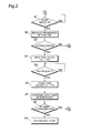
- Step S1 a check is performed as to whether or not the start switch, which indicates that the system is to be started, is in the ON state (Step S1).
- This start switch corresponds to the ignition key for a vehicle that carries an internal combustion engine.
- Step S2 the control unit 80 reads out the hydrogen tank use frequency that is stored in the memory unit 81 (Step S2).
- the frequency of use is an embodiment of the history of use of the hydrogen tank, but the history of use of the hydrogen tank is not limited thereto, but instead may be the cumulative time of use, as described above, or a value that is the product of the cumulative time of use and the tank pressure.
- the control unit 80 performs a check as to whether or not this is a system startup (Step S3).
- Step S3 If this is a system startup (Step S3: YES), then it is necessary to supply and pressurize hydrogen to the hydrogen supply tube 31 and the fuel cell 20.
- Step S4 all of the tank valves VT1 through VT4 are opened (Step S4), and when the detected pressures by the pressure sensors P6 through P8 exceed the threshold pressure PK1 (Step S5: YES), all of the tank valves VT1 through VT4 are closed (Step S6) and a hydrogen leak check is performed (Step S7).
- PK1 a pressure value that is necessary and sufficient for performing a hydrogen leak check for the hydrogen supply tube 31 and the return flow path 32 should be selected.
- Step S7 In the hydrogen leak check (Step S7), all of the electromagnetic shutoff valves B1 through B3 are closed, and with the valves for the hydrogen supply tube 31 and the return flow path 32 tightly closed, a hydrogen leak is detected by whether or not the drop in pressures detected by the pressure sensors P5 through P8 exceed a specific threshold value. If there is a hydrogen leak (Step S8: YES), a system fault stop is performed (Step S9). On the other hand, if not a system startup (Step S3: NO) or if there is no hydrogen leak (Step S8: NO), the control jumps to Step S10.
- Step 10 a check is performed as to whether or not driving is possible. If driving is not possible (Step S10: NO), then the control jumps to Step S38. If driving is possible (Step S10: YES), then the hydrogen tank, from among the hydrogen tanks 51 to 54, for which the frequency of use is the lowest is selected as the hydrogen supply source (Step S 11). When there is a plurality of hydrogen tanks for which the frequency of use is the lowest, then the hydrogen tank with the highest temperature should be selected. Next, a check is performed as to whether or not the temperature TN of the hydrogen tank that is selected as the hydrogen supply source is less than the threshold temperature Tc1 (Step S12).
- the temperature TN is the tank temperature that is detected by the temperature sensors T1 through T4 for the hydrogen tank 51 to 54 that is selected as the hydrogen supply source.
- the threshold temperature Tc1 is the temperature that serves as the criterion for switching tanks in order to control the damage to the hydrogen tank due to the drop in tank temperature, and may be set to the neighborhood of the lower limit temperature T0 of the guaranteed temperature range for the hydrogen tank. For this guaranteed temperature range, a temperature range wherein the tank valves VT1 through VT4, O-rings, etc., of the hydrogen tanks 51 through 54 can withstand use should be selected.
- Step S12 NO
- the frequency of use of the selected hydrogen tank is incremented by 1 (Step S17a)
- the tank valve for the selected hydrogen tank is opened (Step S17b)
- the supply of hydrogen to the fuel cell 20 to generate electricity is started (Step S 18).
- Step S 12 if the temperature TN is less than the threshold temperature Tc1 (Step S12: YES), then the hydrogen tank with the next lowest frequency of use is selected as the hydrogen supply source in order to control the damage to the hydrogen tank (Step S 13), and a check is performed as to whether or not all hydrogen tanks have been selected (Step S 14), and if there are no hydrogen tanks that have not yet been selected (Step S 14: NO), the control loops to Step S 12.
- the damage to the hydrogen tank due to the drop in temperature can be controlled. If at this point the temperatures of all of the hydrogen tanks 51 to 54 are less than the threshold temperature Tc1 (Step S14: YES), then all of the tank valves VT1 to VT4 are opened (Step S15) to supply hydrogen to the fuel cell 20 from all of the hydrogen tanks 51 to 54. Doing so enables the control of the damage to the hydrogen tanks through reducing the amount of temperature drop of the hydrogen tanks by reducing the amount of hydrogen supplied per hydrogen tank.
- Step S16 the output of the fuel cell 20 is controlled based on the hydrogen tank with the lowest temperature, and power generation is started (Step S16).
- the threshold temperature Tc1 is set to the neighborhood of the lower limit temperature T0 in the guaranteed temperature range, a structure may be used wherein all of the tank valves VT1 through VT4 are closed, and the vehicle is stopped, in order to avoid damaging the hydrogen tanks 51 through 54.
- the power required by the load 70 is calculated based on the degree of opening of the accelerator, detected by the accelerator sensor 82, and the vehicle speed detected by the vehicle speed sensor 83 (Step 19), and the power proportion of the fuel cell 20 and the secondary battery (not shown) is calculated (Step 20).
- the amount of energy generated by the fuel cell 20 and the amount of hydrogen consumed by the fuel cell 20 are calculated based on the amount of exhaust of the anode off gas, exhausted from the electromagnetic shutoff valve B3 (Step S21).
- the degree of hydrogen adiabatic expansion (the amount of the drop in temperature) is calculated from the ratio of the internal pressure (tank residual pressure) and the discharge aperture pressure of the supply source tank, of the hydrogen tanks 51, 52, 53, and 54, selected as the hydrogen supply source.
- the degree of adiabatic expansion of the hydrogen can be calculated from the first-stage pressure (the pressure detected by the pressure sensors P1 through P4) of the first-stage regulators A1 through A4, and the second stage pressure (the pressure detected by the pressure sensor P5).
- the amount of heat absorption Q1 of the supply source tank is estimated by calculating the amount of hydrogen consumed and the product of the hydrogen flow times the drop in temperature due to the degree of adiabatic expansion (Step S23).
- the amount of heat Q2 absorbed from the external atmosphere by the supply source tank is calculated based on the external atmosphere temperature detected by the temperature sensor T5 (Step S24), and the total amount of heat absorbed Q, absorbed by the supply source tank, is calculated as "amount of heat absorbed Q1 - amount of heat absorbed Q2" (Step S25).
- the temperature drop AT of the supply source tank is calculated from the heat capacity of the supply source tank, the tank temperature, and the total amount of heat absorbed Q (Step S26).
- Step S28 A temperature lower than the threshold temperature Tc1 and higher than the lower limit temperature T0 of the guaranteed temperature range, for example, should be used as the threshold temperature Tc2 (T0 ⁇ Tc2 ⁇ Tc1). If the temperature TN' is higher than the threshold temperature Tc2 (Step S28: NO), then the processing jumps to Step S38.
- Step S28 YES
- the hydrogen tank with the lowest frequency of use that has not been selected as the hydrogen supply source is selected as the hydrogen supply source in order to avoid damaging the hydrogen tanks (Step S29).
- Step S30 a check is performed as to whether or not the temperature TN of the hydrogen tank that has been selected is less than the threshold temperature Tc1 (Step S30). If TN is less than Tc1 (Step S30: YES), then the hydrogen tank that has the next lowest frequency of use is selected as the hydrogen supply source (Step S31).
- Step S32 a check is performed as to whether or not all hydrogen tanks have been selected (Step S32), and if there is a hydrogen tank that has not yet been selected (Step S32: NO), then the processing loops back to Step S30. If at this point the temperatures of all of the hydrogen tanks 51 to 54 are less than the threshold temperature Tc1 (Step S32: YES), then all of the tank valves VT1 through VT4 are opened (Step S33) to supply hydrogen to the fuel cell 20 from all of the hydrogen tanks 51 to 54. Next, the generation of electricity is begun with the output power of the fuel cell 20 limited, using the hydrogen tank with the lowest temperature as the standard (Step S34).
- a configuration may also be used wherein all of the tank valves VT1 through VT4 are closed and the vehicle is stopped if the temperatures of all of the hydrogen tanks 51 through 54 are less than the threshold temperature Tc1 to begin with (Step S32: YES).
- the temperature TN of the selected hydrogen tank exceeds Tc1 (Step S30: NO)
- the frequency of use of the selected hydrogen tank is incremented by 1 (Step S35)
- the tank valve is opened (Step S36), and the generation of electricity is started in the fuel cell 20 (Step S37).
- Step S38 a check is performed as to whether or not the intermittent operation start conditions have been fulfilled.
- the intermittent operations refer to an operating mode wherein the vehicle is driven by electric power supplied from a power storage device with the operation of the fuel cell 20 halted when there is a low load to the degree that the vehicle can be driven by electric power supplied from an electric power storage device, such as a secondary battery, or the like, when, for example, driving at a low speed or when idling. If the intermittent operation start conditions are not fulfilled (Step S38: NO), then the control jumps to Step S10.
- Step S38 If the intermittent operation start conditions are fulfilled (Step S38: YES), then the tank valves VT1 to VT4 and the electromagnetic shutoff valves V1 to V3 are all closed (Step S39), and the generation of electrical power is halted (Step S40). At this time, a hydrogen leak check may be performed to conform to the safety of the system. This hydrogen leak check may be performed using the same procedure as in Step S7. Next a check is performed as to whether or not the intermittent operating end conditions have been fulfilled (Step S41). If the intermittent operation end conditions have not been fulfilled (Step S41: NO), then the control jumps to Step S38.
- Step S41 YES
- Step S42 YES
- Step S43 a check is performed as to whether or not there has been a request for stopping the system
- Step S43 a request for stopping the system
- Step S43: NO a request for stopping the system
- Step S44 the tank valves VT1 through VT4
- the electromagnetic shutoff valves B1 through B2 are all closed (Step S44), and the system is stopped (Step S45).
- the present form of embodiment selects and switches to the hydrogen tank to become the hydrogen supply sources based on the temperature states of the hydrogen tanks 51 to 54, and thus is able to prevent damage to the hydrogen tanks 51 to 54 by drops in the tank temperature. Moreover, while there is the risk of permanent deformation to the mechanical components, etc., and of a loss of seal quality in hydrogen tanks due to maintaining high pressures for extended periods of time in those hydrogen tanks for which the frequency of use is low, selecting hydrogen tanks using the frequency of use as a selection criterion makes it possible to equalize the frequencies of use of the various hydrogen tanks 51 to 54, which can eliminate this type of problem.
- the invention is not limited thereto, but rather the cumulative times of use of the hydrogen tanks 51 to 54 or the multiplicative products of the cumulative times of use and the tank internal pressures, etc., or other values that can quantitatively evaluate the state of use of the hydrogen tanks 51 to 54 can be used as selection criteria.
- the frequencies of use of the hydrogen tanks 51 to 54 the frequencies of use should not be reset (cleared to 0) when the hydrogen tanks are filled with hydrogen.
- the histories of use of the hydrogen tanks 51 to 54, the temperatures of the tanks, or both in combination may be used as selection criteria.
- the selection criteria may be set using either one as having higher priority.
- the selection criteria were set with the frequency of use having higher priority than the tank temperature, instead the selection criteria may be set with the tank temperature having higher priority than the frequency of use.
- the tank temperatures were estimated from the degree of adiabatic expansion of the hydrogen, which is physical quantity related to the gas that is supplied from the tank, and this estimated temperature was used as the decision criterion for switching tanks
- the tank temperature may be estimated from a physical quantity related to the tank temperature (a physical quantity other than the degree of adiabatic expansion) and this estimated temperature may be used as the decision criterion for switching the tank.
- the aforementioned temperature sensor T1 through T5 and pressure sensor P1 through P5 function as detecting means for detecting physical quantities relating to the temperatures of the hydrogen tanks 51 to 54
- other physical sensor instead may be used to detect physical quantities relating to the tank temperatures. Note that it is not an absolute necessity to perform an estimation calculation for the tank temperatures, but rather the tank temperatures detected by the temperature sensors T1 through T4 may be used as the decision criteria for switching tanks.
- Step S29 the tanks were switched when it was determined that a tank temperature had fallen below the guaranteed temperature range, it is not absolutely necessary to switch the tank, but rather the supply of hydrogen may be continued with a constraint on the amount of hydrogen supplied from the hydrogen tank that is selected as the hydrogen supply source to the fuel cell 20.
- handling measures should be put in place such as limiting the amount of electricity generated by the fuel cell 20, for increasing the amount of electrical power supplied to the load 70 from the electrical power storage device, such as the secondary battery, etc.
- hydrogen tanks 51 to 54 filled with high pressure hydrogen gas were used as an embodiment of a hydrogen supply source
- the invention is not limited thereto, but rather may use, for example, hydrogen occlusion tanks wherein a hydrogen occluding alloy that can reversibly occlude and release hydrogen is filled into tank containers, may be used instead.
- a hydrogen occlusion alloy is an alloy that reacts with hydrogen to form a metal hydride, wherein the hydrogenation and dehydrogenation reactions progress at a favorable reaction speed under practical conditions, and are reversible.
- the hydrogen occluding alloy has the properties of occluding hydrogen and releasing heat when the pressure of the hydrogen gas is increased or the temperature of the hydrogen gas is decreased, and releasing hydrogen and absorbing heat when the pressure of the hydrogen gas is decreased or the temperature of the hydrogen gas is increased.
- Mg-Ni alloys, La-Ni alloys, Ti-Mn alloys, or the like are well suited as hydrogen occluding alloys.
- the number of hydrogen tanks provided in the hydrogen supply device 50 may be only a single tank.
- Fig. 7 is an explanatory diagram showing a schematic configuration of a vehicle 310 according to a second embodiment.
- the vehicle 310 is driven by the driving force of a motor 330, using as a source of electrical power a fuel cell 320 that is installed in a fuel cell compartment 312 in the rear of the vehicle 310.
- the motor 330 may use any of a variety of types, but in the present embodiment a synchronous electric motor is used.
- the direct current outputted from the fuel cell 320 is converted into a three-phase alternating current by an inverter 331.
- the motor 330 is driven by this 3-phase alternating current.
- the motive force of the motor 330 is transmitted to a wheel 333 through a rotating shaft 332 to drive the vehicle 310.
- the fuel cell 320 produces electricity through an electrochemical reaction between hydrogen and oxygen. While any of a variety of types of fuel cells may be used in the fuel cell 320, in the present form of embodiment a solid-state polymer type is used. Air is supplied from the outside through a supply tube 324 to an oxygen electrode. Hydrogen is supplied sequentially through a supply tube 322 from a plurality of hydrogen tanks 350 equipped in a hydrogen tank compartment 311 on the roof. After the air and the hydrogen that is supplied to a hydrogen electrode are used in generating electricity, they are exhausted to the outside from an exhaust tube 323. The configuration of the hydrogen and air supply systems will be described below.
- the operations of the various mechanisms housed in the vehicle 310, such as the inverter 331, are controlled by a control unit 340.
- the control unit 340 is configured as a microcomputer comprising an internal CPU, ROM, RAM, and so forth, where the operations of each unit are controlled according to a control program stored in the ROM.
- Fig. 7 shows the functional blocks of the control unit 340.
- these functional blocks are constituted in software in the control unit 340.
- each functional block may be constituted in hardware instead.
- the sensor input unit 341 receives and applies the inputs of signals from various types of sensors equipped in the vehicle 310.
- the sensors included, for example, temperature sensors and pressure sensors equipped in the supply systems that supply hydrogen and air to the fuel cell 320.
- the detection signals from the sensors include the degree of opening of the accelerator, which corresponds to the required power when driving.
- An electricity generation control unit 344 controls the generation of electricity of the fuel cell 320 depending on the required power.
- a supply control unit 345 supplies hydrogen to the fuel cell 320, divided into the individual hydrogen tanks 350, depending on the amount of electricity to be generated by the fuel cell 320.
- a motor control unit 346 controls the driving of a motor 330 so as to output the required power using the electrical power of the fuel cell 320.
- An instrument control unit 343 controls the display on an instrument panel 360 equipped at the driver's seat 314 of the vehicle 310.
- This display includes the speed, the rpm of the motor 330, the temperature of the fuel cell 320, the shaft position, and so forth.
- the display also includes displays of the amount of remaining hydrogen, and fault displays for the supply system for the hydrogen tanks 350.
- Fig. 8 is an explanatory diagram showing the configuration of the gas supply system to the fuel cell 320.
- compressed air as a gas containing oxygen, is supplied to a cathode, and hydrogen is supplied to an anode.
- the air is drawn in through a filter 325 and is compressed in a compressor 326, after which the air is humidified by a humidifier 327, and is supplied through a supply tube 324.
- a pressure sensor 328 for detecting the supply pressure of the air is equipped in the supply tube 324.
- the hydrogen is supplied from four hydrogen tanks 350 through a supply tube 322 to the anode.
- each tank is assigned a tank number 1 through 4, for convenience in the explanation.
- the individual hydrogen tanks 350 will be referred to identified as the first tank through the fourth tank, according to the tank number. Because the hydrogen flows from the hydrogen tanks 350 to the fuel cell 320 in the gas supply system, for convenience in the explanation the side nearer the hydrogen tank 350 will be referred to as the upstream side, and the side nearer the fuel cell 320 will be referred to as the downstream side.
- Each hydrogen tank 350 stores hydrogen at a high pressure of approximately 350 atmospheres.
- the hydrogen tanks 350 are equipped with regulators 355 for reducing the pressure of the hydrogen, and valves 351 that are opened and closed electromagnetically by control signals by the control unit 340.
- the hydrogen pressure is reduced stepwise along the supply tube 322 before being supplied to the fuel cell 320, but the pressure-reduction mechanisms are not shown in the drawing.
- the hydrogen tanks 350 are equipped with temperature sensors 353 on the downstream sides of the regulators 355.
- the temperature sensors 353 are equipped at positions that are able to detect the temperatures of the hydrogen after pressure reductions by the regulators 355.
- the positions wherein the temperature sensors 355 are installed are not limited to the positions shown in the figure, but rather a variety of positions can be selected for measuring, either directly or indirectly, the operating temperatures of the regulators 355 and valves 351.
- the temperature of the gas that is supplied from the hydrogen tank 350 falls due to adiabatic expansion when the pressure is reduced.
- the hydrogen tanks 350 are equipped with heaters 352 to not only curtain this drop in temperature, but also to expedite the recovery of the temperatures of the hydrogen tanks after the temperatures have fallen.
- the hydrogen tanks 350 are equipped with pressure sensors 354, on the upstream sides of the regulators 355 in order to measure the storage pressures within the tanks.
- the supply tube 322 is also equipped with a pressure sensor, separate from these pressure sensors 354 for detecting the supply pressure of the hydrogen.
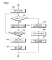
- Fig. 9 is a flow chart showing the monitoring procedure at startup, performed by the control unit 340.
- the control unit 340 performs the startup monitoring procedure when there has been an instruction to run the fuel cell 320, such as the driver operating the start switch.
- the control unit 340 opens the valves 351 in order to fill the supply tube 322 with hydrogen gas (Step S310a). After the supply tube 322 has been filled with hydrogen gas, the valves 351 for all of the hydrogen tanks 350 are closed (Step S310b), and the supply pressure Pa of the supply tube 322 is detected by the pressure sensor 329 (Step 311 a). Because the supply of hydrogen is stopped by the closing of the valves 351, under normal circumstances the supply pressure Pa should fall due to the hydrogen gas in the supply tube 322 escaping to the fuel cell 320.
- the fuel cell 320 is run briefly to perform a pressure reduction procedure through consuming the hydrogen within the supply tube 322 in order to make it possible to detect, in a short period of time, the changes in the supply pressure Pa (Step 311b).
- the supply pressure Pa in the supply tube 322 is detected again (Step S311 c), to detect whether or not the supply pressure Pa has dropped during the pressure reduction procedure (Step S312). If the supply pressure Pa has not dropped (Step S312), then the control unit 340 concludes that either there is a leak in the valve 351 of one of the hydrogen tanks 350, or that the valve 351 is stuck in the open position, and the control unit 340 performs a fault determination procedure (Step S318).
- the fault determination procedure may be, for example, a procedure to set a fault determination flag that indicates the existence of a fault.
- Step S312 If the pressure Pa has dropped (Step S312), then the control unit 340 performs checks, in the sequence below, as to whether or not each individual valve 351 (1) through 351 (4) has opened correctly, for each hydrogen tank 350 (1) through 350 (4).
- the control unit 340 selects one of the hydrogen tanks 350 as the tank to be tested, opens the valve 351 for the tank to be tested (Step S313), and detects the supply pressure Pa (Step S314). If the valve 351 has opened correctly, then hydrogen should be supplied from the tank being tested, so the supply pressure Pa should rise. If the supply pressure Pa does not rise (Step S315), then the control unit 340 concludes that the valve 351 had a fault in its opening operation, and performs a fault determination procedure (Step S318).
- Step S315) If the supply pressure Pa rises (Step S315), then the control unit 340 concludes that the valve 351 is normal, and closes the valve 351 of the tank being inspected (Step 316).
- the control unit 340 performs the check procedure of Steps S311a through S316 for all of the hydrogen tanks 350 (1) through 350 (4) while changing the tank to be inspected each time.
- performing the monitor procedure at startup as described above can increase the reliability of the operations of the valves 351 when switching the hydrogen tanks 350 used as the supply source.
- Step S312 it may be concluded that the supply pressure has fallen when, for example, the supply pressure Pa falls below a specific threshold.
- the supply pressure Pa has fallen when the absolute value of the temporal rate of reduction of the supply pressure Pa is greater than a specific threshold.
- Step S315 the conclusion may be based on the relative magnitude of the supply pressure Pa and a threshold value, or the conclusion may be based on the rate of change of the supply pressure Pa.
- Fig. 10 is a flow chart illustrating the gas supply control performed by the control unit 340.
- the control unit 340 iteratively performs the gas supply control in order to supply hydrogen in the amount that is required for the operation of the fuel cell 320, divided into the individual hydrogen tanks 350.
- control unit 340 inputs a required power based on the degree of opening of the accelerator (Step S320), and sets the amount of gas to be supplied (Step S321).
- the amount of gas to be supplied can be calculated based on a map, a coefficient, or the like that provides the amount of gas to be supplied in relation to a given power requirement.
- the control unit 340 specifies the supply source for the gas (Step S330).
- the hydrogen is supplied by switching sequentially the hydrogen tank 350 that serves as the supply source.
- the adiabatic expansion causes the temperature of the hydrogen to drop extremely. This drop in temperature can have negative effects such as failures in the opening/closing operations, reduced useful life spans, reduced performance, etc., caused by the hardening of resin components in the valves 351.
- the supply source is changed sequentially in order to avoid continuously supply hydrogen from any single hydrogen tank 350 to the degree that would lead to these problems.
- the gas supply source designation procedure is a procedure that selects the hydrogen tank 350 to be used as the supply source based on the approach described below. The details of the gas supply source designation procedure are described below.
- the control unit 340 controls the valve 351 of the selected hydrogen tank 350 to supply the gas (Step S340). If, for reasons of a fault, etc., in the regulator 355 or the valve 351, it is not possible to supply the gas (Step S341), then the gas supply source designation procedure is performed again (Step S330), and an attempt is made to supply the gas from another hydrogen tank 350. In Step 341, the control unit 340 may conclude that there is a fault in the supply of the gas when, for example, the supply pressure Pa of the supply tube 322 has fallen. When it is concluded that there is a fault in the supply, then a fault determination flag should be set, as already explained in the check procedures at startup (Fig. 9).
- the control unit 340 notifies the driver that there is a fault (Step S350) if, in the check procedure at startup (Fig. 9) or in the procedures in Steps S320 through S341, described above, a hydrogen tank is discovered to have a fault (Step S342). This procedure will be described below. If there is no fault, then the control unit 340 skips the fault notification procedure (Step S350).
- the control unit 340 performs heating, using a heater (Step S360) so that the drop in temperature of the valves 351 of each of the hydrogen tanks 350 accompanying the supply of hydrogen will not be too great.
- the control of power to the heater will be described below.
- the control unit 340 supplies hydrogen so as to be able to generate electricity commensurate with the required power, doing so through iterating the procedures described above.
- the gas supply control procedure shown in Fig. 10 is not more than one embodiment, where the various procedures in this gas supply control procedure may be performed in different processing orders, or may be performed in parallel, as appropriate.
- Fig. 11 is a flow chart showing the gas supply source designation procedure performed by the control unit 340.
- the gas supply source designation procedure is the procedure corresponding to Step S330 of the gas supply control (Fig. 10), described above, a procedure for selecting the hydrogen tank 350 to serve as the supply source so as to avoid damage accompanying a drop in temperature due to the adiabatic expansion of the hydrogen.
- the supply source is selected based on the detection values by the temperature sensors 353 and pressure sensors 354 of the individual hydrogen tanks 350.
- the control unit 340 detects the temperature T and the pressure P for the hydrogen tank 350 that is currently the supply source (hereinafter termed the "current tank") (Step S331). Initially, when this procedure is performed, or in other words, when there is no current tank, the procedure is performed with both the temperature T and the pressure P defined as 0. Moreover, the control unit 340 stores, as the initial temperature T0, the temperature T at the point in time when the use of the current tank is started.
- the control unit 340 switches the current tank when the condition "temperature T ⁇ threshold value Ta" is fulfilled (Step S332). When this condition is not fulfilled, the current tank continues to be used, and the gas supply source designation procedure is terminated.
- the condition of "temperature T ⁇ threshold value Ta" is the condition for preventing the temperature of the current tank from dropping to far.
- - 10°C is used as the threshold value temperature Ta.
- the threshold value Ta can be set to the minimum temperature wherein normal operation can be insured for the various components such as the regulator 355 and the valve 351, or can be set to a temperature a specific amount higher than this minimum temperature.
- the threshold value Ta can be set to a temperature that is a temperature that is a specific amount lower than the tank temperature when the current tank was switched, and higher than the lower limit temperature, for example, set to a temperature that is 5°C lower than the temperature that the tank was when the supply source was switched.
- the threshold value Ta may be set so as to fulfill the condition "temperature T ⁇ threshold value Ta" when the difference between the tank temperature and the temperature of another hydrogen tank 350 that is not the current tank (for example, the difference with the average tank temperature of the other hydrogen tanks 350) reaches a specific temperature difference.
- Step S332 if it is determined that the current tank should be switched, and then the control unit 340 closes the valve 351 on the current tank (Step S333). Following this, those tanks among the hydrogen tanks 350 that are not the current tank and that have tank temperatures at or above the threshold value Ta are identified as candidate tanks (Step S334). A plurality of candidate tanks may be identified.
- the control unit 340 selects from the identified candidate tanks the tank to become the supply source (Step S335).
- the tank to become the supply source may be selected based on a variety of criteria, but in the present embodiment, the following three criteria are used:
- the aforementioned criteria are applied with the priority sequence being a) through c), that is, first the tank with the highest temperature is selected from the plurality of candidate tanks based on criterion a). If there is a plurality of candidate tanks selected in this way, then next the tank with the greatest amount of the gas remaining, or in other words, the tank with the greatest pressure P, is selected based on criterion b). If there is still a plurality of candidates, then the selection is done using a preexisting sequence, such as "first tank ⁇ second tank ⁇ third tank ⁇ fourth tank," based on criterion c).
- These criteria may be set in a variety of ways, for example, any single one of the criteria a) through c) may be used, or the criteria a) through c) may be applied with a different priority order than which is described above.
- Fig. 12 is an explanatory diagram showing an embodiment of selecting a supply source. The changes in pressure and temperature of the first tank (#1) through the fourth tank (#4) over time are shown. In this embodiment, the explanation is of a situation wherein the sequence of "first tank ⁇ second tank ⁇ third tank ⁇ fourth tank" has been set.
- the first tank is selected as the supply source based not on criterion a) which is based on temperature nor on criterion b) which is based on the amount of hydrogen remaining, but rather on the sequence of criterion c).
- the pressure P1 in the first tank drops, and the temperature t1 drops commensurately.
- the temperature in the first tank reaches the threshold value Ta, and so the supply source is switched.
- the candidate tanks are the second tank through the fourth tank.
- the pressures P2 through P4 and the temperatures T2 through T4 of these tanks are all identical. Consequently, the tank following the first tank, or in other words, the second tank, is selected by the sequence of criterion c) as the supply source tank.
- the candidate tanks are the first tank, the third tank, and the fourth tank.
- the pressures P1, P3 and P4, and the temperatures T1, T3 and T4 of each of these tanks have the following relationships:
- the first tank which has the lowest temperature, is excluded as a candidate for the supply tank, so the candidate tanks are the third tank and the fourth tank. If the end, the tank following the second tank in the sequence in criterion c), or in other words, the third tank, is selected as the supply source tank.
- the candidate tanks at this time are the first tank, the second tank, and the fourth tank.
- the pressures P1, P2, and P4, and the temperatures T1, T2, and T4 of each of these tanks have the following relationships:
- the fourth tank which has the highest temperature, is selected as the supply source tank by criterion a).
- the supply source tanks can be selected as appropriate through the application of the criteria a) through c) in this same manner.
- Fig. 13 is a flow chart illustrating the procedure for fault notification performed by the control unit 340.
- the fault notification procedure is the procedure corresponding to Step S350 in the gas supply control procedure (Fig. 10) and is the procedure for notifying the driver of the existence of a fault in any of the four hydrogen tanks 350.
- the control unit 340 inputs the fault check results (Step S351).
- the fault determination flags set in the check procedure at startup (Step S318 in Fig. 9) or the gas supply control procedure (Step S341 in Fig. 10), for example, can be used.
- the specific individual tank wherein there is a fault, of the first tank through the fourth tank can be specified based on the fault determination flags.
- the control unit 340 calculates the amount of gas remaining, excluding the tank wherein there is the fault (Step S352).
- Fig. 13 shows a method of calculating the amount of remaining gas, using as an embodiment the case wherein a fault has been detected in the fourth tank. As is shown in the figure, the amounts of gas remaining in the first tank through the fourth tank, at the point in time prior to the detection of the fault were R1 through R4, respectively.
- the total amount of remaining gas Rold is calculated as "R1 + R2 + R3 + R4.”
- the control unit 340 ignores the amount of gas R4 remaining in the fourth tank when a fault has been detected in the fourth tank, and thus the total amount of gas remaining Rnew is calculated as "R1 + R2 + R3.”
- the control unit 340 not only corrects the display of the amount of gas remaining based on the results of calculating the amount of gas remaining, but also provides a warning display to the driver (Step S353).
- Fig. 13 shows an embodiment of an instrument panel 360 for a vehicle 310.
- the left side of the instrument panel 360 is equipped with a remaining gas gauge 361, a remaining gas warning lamp 362, and fault warning lamps 363 for each of the tanks. Because the amount of gas remaining will be decreased rapidly by the calculation in Step S352, the value displayed on the remaining gas gauge 361 will also drop, as shown in the figure, to Rold from Rnew.
- the control unit 340 flashes the remaining gas warning lamp 362 for a specific amount of time, regardless of the value for the amount of gas remaining Rnew, in order to inform the driver that the display of the remaining gas gauge 361 has been corrected. Instead of flashing the remaining gas warning lamp 362, the indicator of the remaining gas gauge 361 may be vibrated instead.
- control unit 340 also light or flashes the fault warning lamp 363 for the hydrogen tank 360 for which the fault was discovered.
- a situation is shown wherein a fault has been discovered in the fourth tank.
- Fig. 14 is a flow chart illustrating the heater heating procedure performed by the control unit 340. This procedure corresponds to Step S360 in the gas supply control procedure (Fig. 10), and is a procedure for controlling whether or not to apply a current, and controlling the magnitude of the aforementioned current, to heaters 352 in each of the hydrogen tanks 350.
- the control unit 340 performs the heater heating procedure for each of the individual hydrogen tanks 350.
- the hydrogen tank 350 that is the subject of the control of the heater heating procedure will be termed the "applicable tank.”
- the control unit 340 receives an input of the temperature T for the applicable tank (Step S361). The control unit 340 concludes that heating using the heater 352 is unnecessary if this temperature T is greater than a target temperature Th that is set in advance, and turns off the current to the heater 352 (Step S363).
- the target temperature Th may be set based on, for example, a temperature for which the operation of various components of the hydrogen tank 350, such as the regulator 355 or the valve 351, are guaranteed to operate. In the present embodiment, the target temperature Th is set to 0°C.
- the control unit 340 calculates the amount of difference dT between the target temperature Th and the temperature T of the applicable tank (Step S364). This amount of difference dT corresponds to the amount of increase in temperature required for the applicable tank.
- the control unit 340 calculates the time required until changing, or in other words, the time required Tc until the applicable tank, which is the subject of control, can be used again, doing so using the following formula (Step S365).
- T c N t ⁇ T a v
- Nt is the number of interval tanks
- Tav is the average time over which continuous use is possible.
- the average time over which continuous use is possible Tav is the average time for which hydrogen can be supplied continuously from a single hydrogen tank 350 without the temperature dropping too far, which can be calculated for, for example, the previous supply history.
- the average amount of time for which continuous use is possible Tav may be a constant, set, for example, to the time over which hydrogen can be supplied continuously without the temperature dropping too far when hydrogen is supplied at the maximum supply rate.
- the control unit 340 calculates the amount of heat Qr required per unit time using the following formula based on the values calculated in Steps S364 and S365 (Step S366).
- Q r d T ⁇ C t / T c
- Ct is the heat capacity of the tank.
- the required heat Qr indicates the amount of heat that must be supplied per unit time in order to raise the temperature of the applicable tank to the target temperature Th after a specific amount of time Tc.
- the temperature of the hydrogen tank 350 can be stabilized and restored to the target temperature Th by setting the required heat Qr in this way.
- control unit 340 sets the amount of heating Hr per unit time by the heater 352 based on the following formula, and controls the electric current to the heater 352 based thereon (Step S367).
- H r max ( Q r ⁇ Q n , H min )
- Max (A, B) is an operator that selects the larger of the two values A and B.
- the amount of heat Qn through natural heating can be set in advance experimentally or analytically.
- the minimum amount of heat Hmin is the amount of heat that must be supplied, unconditionally, through the heater 352.
- the heating is performed according to the minimum amount of heat Hmin when the applicable tank is used as the supply source for the hydrogen, or when the temperature of the applicable tank has approached the target temperature Th.
- the minimum amount of heat Hmin to a large value enables the prevention of a temperature drop when the applicable tank is used as the supply source for the hydrogen. Consequently, this has the benefit of being able to extend the time over which the tank can be used to supply hydrogen continuously, reducing the frequency with which the hydrogen tanks 350 are changed. If the minimum amount of heat Hmin is set to a small value, then the amount of energy consumed in the electric current to the heater 352 can be reduced, which has the benefit of increasing the energy efficiency in the fuel cell system.
- the minimum amount of heat Hmin can be set as desired, taking into consideration the need to prevent temperature drops in this way, and the need to increase energy efficiency.
- Steps S364 through S366, described above may be omitted. That is, when the temperature T of the applicable tank is less than the target temperature Th, then the control unit 340 may apply an electric current to the heater 352 heating with the minimum amount of heat Hmin that has been set in advance, unconditionally.
- a plurality of hydrogen tanks 350 are used through switching the hydrogen tanks 350 depending on the temperature downstream of the regulators 355. This makes it possible to prevent the temperatures of various components, such as the regulators 355 and the valves 351, from dropping too far, thereby preventing a variety of problems, such as faults in the valve operations, decreased useful life spans of components, decreased performance, and so forth, caused by low temperatures.
- Fig. 15 is a flow chart showing a first modified embodiment of the gas supply source designation procedure.
- the gas supply source designation procedure shown in Fig. 15 is a procedure corresponding to Step S330 in the gas supply control (Fig. 10) described above.
- the supply source is selected based on the detection values of the pressure sensors 354 in a configuration wherein the temperature sensors 353 of each of the hydrogen tanks 350 have been omitted.
- the control unit 340 detects the change in pressure dP for the current tank, which is the hydrogen tank 350 that is currently supply the hydrogen (Step S331A).
- the control unit 340 switches the current tank when the condition of "change of pressure dP > threshold value X" is fulfilled (Step S332A). If any of the conditions are not fulfilled, then the use of the current tank is continued, and the gas supply source designation procedure is terminated.
- the condition of change in "pressure dP > threshold value X" (Step S332) is a condition for avoiding too great a temperature drop in the current tank based on a change in temperature estimated from the change in pressure.
- T1 is the temperature (K) after the adiabatic expansion, and Ts is the initial temperature (K) prior to the adiabatic expansion.
- P1 is the pressure after the adiabatic expansion, and Ps is the initial pressure prior to the adiabatic expansion.
- the temperature of the hydrogen after the reduction is pressure is dependent on the pressure Ps in the hydrogen tank 350; however, when setting the threshold X this temperature can be treated as a constant, independent of the pressure Ps, and thus the temperature of the hydrogen that is expelled can be handled as a constant.
- This constant value can be set based on, for example, the adiabatic expansion from the maximum pressure in order to set the constant value on the safe side from the perspective of preventing the temperature from dropping too far. Because the drop in temperature of the hydrogen tank 350 due to the expelled hydrogen depends on the amount of flow, the maximum discharge flow must be assumed when setting the threshold value X.
- the amount of hydrogen discharge Y (Pa/°C) required to drop the temperature of the hydrogen tank 350 by 1°C can be established experimentally or analytically.
- the use of pressure in the units for the amount of discharge Y is because the amount of discharge of hydrogen is proportional to the change in pressure in the hydrogen tank 350.
- the amount of discharge Y can be used in calculating the amount of discharge (Pa) of hydrogen required to drop the temperature of the hydrogen tank 350 from the initial temperature, or in other words, from the target temperature Th controlled by the heater, to the threshold value Ta.
- the amount of discharge is used as the threshold value X.
- the threshold value X is shown as a condition based on the change in pressure in the hydrogen tank 350 in the formula above, in practice the condition can be based on the amount of hydrogen discharged from the hydrogen tank 350. Moreover, the threshold value X is set assuming the condition of the most severe drop in temperature, making it possible to prevent, with greater certainty, too large a drop in the temperature of the hydrogen tank 350.
- the temperature of the hydrogen that is discharged varies depending on the pressure P in the hydrogen tank 350, and thus the amount of discharge Y (Pa/°C) of hydrogen required to drop the temperature of the hydrogen tank 350 by 1 °C is also dependent on the pressure P.
- the value of the aforementioned amount of discharge Y may be set based on a map or coefficient prepared in advance depending on the initial pressure Pini of the current tank.
- Step S332A if it is determined that the current should be switched, the control unit 340 closes the valve 351 of the current tank (Step S333A). After this, the hydrogen tank 350 to become the supply source is selected from the hydrogen tanks 350, excluding the current tank, based on the two criteria of a) the amount of remaining hydrogen and b) a preexisting sequence. In the modified embodiment the temperature sensors are omitted, and thus criteria pertaining to temperature are not applicable.
- the temperature sensors are omitted, which is able to simplify the structure while still preventing too great a drop in temperature of the hydrogen tanks 350, in the same manner as in the embodiment.
- the first modified embodiment can be applied also to systems wherein both the temperature sensors and the heating by heaters are omitted.
- control is performed assuming that the hydrogen tank 350, for which the temperature has dropped because of the expulsion of hydrogen corresponding to the threshold value X (Pa) returns to the initial temperature T0 through natural heating through reducing the supply of hydrogen when hydrogen is supplied from another hydrogen tank 350.
- materials or structures that increase the absorbance of heat may be used in the regulator 355 equipped in the hydrogen tank 350.
- Fig. 16 is a flow chart showing a second modified embodiment of a gas supply source designation procedure.
- the gas supply source designation procedure shown in Fig. 16 is a procedure corresponding to Step S330 in the gas supply control (Fig. 10), described above.
- the supply source tank is selected so as to minimize the temperature differences between each of the hydrogen tanks 350, according to the temperatures of each of the hydrogen tanks 350.
- the temperature drop Tdc is a specific temperature that is set in order to minimize the temperature difference between the individual hydrogen tanks 350, and in the present embodiment is set in advance to 5 °C.
- Step S420 If the current tank temperature Tep has not dropped by the temperature drop Tdc (Step S420), then hydrogen supply from the current tank is continued (Step S460), and the gas supply source designation procedure is terminated.
- Step S420 If the current tank temperature Tep has dropped by the temperature drop Tdc (Step S420), then hydrogen supply from the current tank is stopped (Step S430), and the hydrogen tank 350 that has the highest temperature of the hydrogen tanks 350 (1) through 350 (4) is designated as the supply source tank, the supply source tank is switched (Step S440), and the gas supply source designation procedure is terminated.
- the temperatures of the plurality of hydrogen tanks 350 are equalized, making it possible to control the damage due to the drop in temperature accompanying the gas supply.
- the temperature drop Tdc is not limited to being 5°C, but rather can be set to a specific temperature depending on system characteristics, environment of use, amount of hydrogen supply, and so forth. Moreover, the temperature drop Tdc needed not be a constant value for a specific temperature drop, but rather may be changed as appropriate during system operation according to system conditions. For example, the value of the temperature drop Tdc may be increased, at higher tank temperatures. Doing so makes it possible to reduce the frequency with which tanks are switched at high temperatures, where there is a relatively low possibility of damage to the components on the tanks.
- the temperature differences between the individual hydrogen tanks 350 may be reduced through switching the supply source tank when the temperature difference of the current tank from the average temperature of the other hydrogen tanks 350, or when a specific amount of time has elapsed after the supply source tank has been switched.
- the supply of hydrogen may be performed in the range of the guaranteed temperature range of the hydrogen tanks 350.
- Fig.17 is a flow chart showing a third modified embodiment of a gas supply source designation procedure.
- the gas supply source designation procedure shown in Fig. 17 is a procedure corresponding to Step S330 of the gas supply control (Fig. 10), explained above.
- the supply source tank is selected so as to reduce the temperature differences and pressure differences between the individual hydrogen tanks 350 based on the temperatures and pressures of the individual hydrogen tanks 350.
- F ⁇ A ⁇ ( T ( N ) ⁇ T a v e ) 2 + ⁇ B ⁇ ( P ( N ) ⁇ P a v e ) 2
- A is the coefficient related to the hydrogen tank temperature T (N).
- B is the coefficient related to the hydrogen tank pressure P (N).
- the A and B are set to specific values suited to reduce the temperature differences and pressure differences between the various hydrogen tanks 350.
- Tave is the average temperature for all of the hydrogen tanks 350.
- Pave is the average pressure for all of the hydrogen tanks 350.
- the third modified form is able to control the drop in use frequency of those hydrogen tanks 350 that, among the plurality of hydrogen tanks 350, have the tendency to be at lower temperatures due to the installation environment (for example, due to the state of exposure to sunlight, positioning relative to heat-producing equipment, etc.). Moreover, when each of the hydrogen tanks 350 have the same capacity, this third modified embodiment is able to equalize the gas density within the various hydrogen tanks 350.
- Equation (5) which expresses the supply source designation value F, it possible to prevent excessive switching of the hydrogen tanks 350 by:
- the hydrogen supply may be performed in the range of the guaranteed temperature range of the hydrogen tanks 350.
- the amount of gas that can be supplied without too great a drop in temperature may be calculated taking into account the temperature of the external atmosphere around the hydrogen tanks 350 and the temperatures of the hydrogen tanks 350 when switching the supply source tanks at a temperature immediately prior to the lower limit temperature of the guaranteed temperature range, to limit the supply of gas after the calculated amount of gas has been discharged.
- Processing may be performed combining the second embodiment and the gas supply source designation processes in the modified embodiments (Fig.11 and Fig. 15).
- a method may be used wherein it is decided that the current tank should be switched when either commission is the field. Doing so makes it possible to prevent the possibility of an incorrect decision regarding switching.
- the invention is not limited to these embodiments, but rather, of course, may be applied to a variety of configurations without deviating from the intent thereof.
- the invention can be configured as a system by which to provide gas to a stationary fuel cell, rather than just a fuel cell mounted on a vehicle.
- the invention can be applied to gas supply apparatus for supplying a variety of gases at reduced pressures from a plurality of high-pressure tanks, rather than being limited to hydrogen alone. While the embodiments and modified embodiments illustrated cases wherein a single hydrogen tank 350 was selected as the supply source, instead a plurality of hydrogen tanks 350 may be selected simultaneously.
- the hydrogen tanks 350 were heated by a heater 352
- the hydrogen tanks 350 may be heated through the use of waste heat from a heat-producing unit such as the fuel cell 320 or the inverter 331.
- a refrigerant may be circulated between the surfaces of each of the hydrogen tanks 350 and the heat-producing unit to perform the exchange of heat between the heat-producing unit and each of the hydrogen tanks 350.
- the exchange of heat may be performed between the various hydrogen tanks 350 by circulating a refrigerant between the various hydrogen tanks 350.
- the invention may be applied to gas supply apparatus for supplying, to the outside, gas that is stored in the tank. Moreover, the invention may be used not only in gas supply apparatus for handling hydrogen, but also in gas supply apparatus for handling a variety of gases such as oxygen, nitrogen, and air.
Applications Claiming Priority (3)
| Application Number | Priority Date | Filing Date | Title |
|---|---|---|---|
| JP2003201509 | 2003-07-25 | ||
| JP2004023985 | 2004-01-30 | ||
| PCT/JP2004/010579 WO2005010427A1 (ja) | 2003-07-25 | 2004-07-16 | ガス供給装置 |
Publications (3)
| Publication Number | Publication Date |
|---|---|
| EP1653148A1 true EP1653148A1 (de) | 2006-05-03 |
| EP1653148A4 EP1653148A4 (de) | 2015-11-18 |
| EP1653148B1 EP1653148B1 (de) | 2018-05-02 |
Family
ID=34106840
Family Applications (1)
| Application Number | Title | Priority Date | Filing Date |
|---|---|---|---|
| EP04747942.3A Expired - Fee Related EP1653148B1 (de) | 2003-07-25 | 2004-07-16 | Gaszufuhrsystem |
Country Status (5)
| Country | Link |
|---|---|
| US (1) | US7575012B2 (de) |
| EP (1) | EP1653148B1 (de) |
| JP (1) | JP4622857B2 (de) |
| KR (1) | KR100672273B1 (de) |
| WO (1) | WO2005010427A1 (de) |
Cited By (14)
| Publication number | Priority date | Publication date | Assignee | Title |
|---|---|---|---|---|
| EP1821031A2 (de) * | 2006-02-14 | 2007-08-22 | Angstrom Power Inc. | Brennstoffzellenvorrichtungen und Verfahren dafür |
| WO2009046933A1 (de) * | 2007-10-02 | 2009-04-16 | Diehl Aerospace Gmbh | Mobiler generator für die bodenstromversorgung des bordnetzes, insbesondere eines abgestellten luftfahrzeuges |
| DE102006031875B4 (de) * | 2005-07-12 | 2009-04-30 | GM Global Technology Operations, Inc., Detroit | Verfahren zum Öffnen von Tankabsperrventilen in Gaszufuhrsystemen mit verbundenen Tanks |
| WO2009071435A1 (de) * | 2007-12-06 | 2009-06-11 | Robert Bosch Gmbh | Verfahren zur regelung der gasentnahme |
| EP1935844A4 (de) * | 2005-09-07 | 2009-09-16 | Toyota Motor Co Ltd | Wasserstoffzufuhrvorrichtung und brennstoffgaszufuhrvorrichtung |
| EP2149596A1 (de) * | 2007-04-19 | 2010-02-03 | Toyota Jidosha Kabushiki Kaisha | Odoranszugabevorrichtung und brennstoffgaszufuhrvorrichtung |
| WO2010022836A1 (de) * | 2008-08-27 | 2010-03-04 | Daimler Ag | Verfahren und vorrichtung zum betreiben eines gastankbehälters in einem fahrzeug |
| US8056577B2 (en) | 2006-03-20 | 2011-11-15 | Tescom Corporation | Apparatus and methods to dispense fluid from a bank of containers and to refill same |
| DE102012005689B3 (de) * | 2012-03-21 | 2013-08-22 | Audi Ag | Verfahren zum Versorgen eines Antriebsaggregats |
| EP2728242A1 (de) * | 2012-11-05 | 2014-05-07 | Magna Steyr Fahrzeugtechnik AG & Co KG | Druckspeichersystem und Verfahren zum Betreiben eines Druckspeichersystems |
| EP3067614A1 (de) * | 2015-03-13 | 2016-09-14 | Kabushiki Kaisha Kobe Seiko Sho (Kobe Steel, Ltd.) | Gasversorgungssystem, wasserstoffstation damit, akkumulatorlebensbeurteilungsverfahren und verwendungsverfahren des gasversorgungssystems |
| EP2466188A3 (de) * | 2010-12-18 | 2017-08-23 | The Boeing Company | Thermodynamische Durchflusspumpe |
| DE112009005107B4 (de) * | 2009-07-29 | 2017-10-19 | Toyota Jidosha Kabushiki Kaisha | Gasabfüllsystem |
| DE102020112830A1 (de) | 2020-05-12 | 2021-11-18 | Bayerische Motoren Werke Aktiengesellschaft | Steuereinheit und Verfahren zum Betrieb eines Druckbehälter-Ventils eines Druckbehälters |
Families Citing this family (70)
| Publication number | Priority date | Publication date | Assignee | Title |
|---|---|---|---|---|
| US7325561B2 (en) | 2004-12-02 | 2008-02-05 | Honda Motor Co., Ltd. | Hydrogen vehicle gas utilization and refueling system |
| JP2006269330A (ja) * | 2005-03-25 | 2006-10-05 | Suzuki Motor Corp | 水素供給装置 |
| JP4956906B2 (ja) * | 2005-03-29 | 2012-06-20 | トヨタ自動車株式会社 | 燃料電池システムおよび水素漏れ検出方法 |
| JP4940573B2 (ja) * | 2005-05-02 | 2012-05-30 | トヨタ自動車株式会社 | 燃料ガス供給装置 |
| US9142844B2 (en) * | 2005-05-18 | 2015-09-22 | Sprint Communications Company L.P. | Power system for a telecommunications network |
| JP4863651B2 (ja) * | 2005-06-09 | 2012-01-25 | 本田技研工業株式会社 | 燃料電池システム |
| JP2007043846A (ja) | 2005-08-04 | 2007-02-15 | Toyota Motor Corp | 移動体 |
| JP4760353B2 (ja) * | 2005-12-14 | 2011-08-31 | トヨタ自動車株式会社 | 液体水素タンク残量検知システム |
| JP4744285B2 (ja) * | 2005-12-19 | 2011-08-10 | 本田技研工業株式会社 | 水素自動車のガスの使用及び補給システム |
| ATE450401T1 (de) * | 2005-12-21 | 2009-12-15 | Honda Motor Co Ltd | Wasserstoffgasversorgungs- und betankungssystem für fahrzeug |
| JP2007242122A (ja) * | 2006-03-07 | 2007-09-20 | Mitsubishi Electric Corp | ディスク再生装置 |
| US7905252B2 (en) | 2006-03-20 | 2011-03-15 | Tescom Corporation | Apparatus and methods to dispense fluid from a bank of containers and to refill same |
| JP4795825B2 (ja) * | 2006-03-24 | 2011-10-19 | 大陽日酸株式会社 | ガス供給装置およびガス供給方法 |
| TWM318100U (en) * | 2006-11-23 | 2007-09-01 | Grand Hall Entpr Co Ltd | Gas storage detection and leakage alerting apparatus |
| JP4849332B2 (ja) * | 2006-11-24 | 2012-01-11 | トヨタ自動車株式会社 | 燃料供給装置 |
| US9061450B2 (en) | 2007-02-12 | 2015-06-23 | Cree, Inc. | Methods of forming packaged semiconductor light emitting devices having front contacts by compression molding |
| US9263751B2 (en) * | 2007-02-26 | 2016-02-16 | GM Global Technology Operations LLC | Method to reduce pressure when injectors are stuck open under faulted conditions and remedial action to prevent walk-home incident |
| JP4941730B2 (ja) * | 2007-03-08 | 2012-05-30 | トヨタ自動車株式会社 | 燃料供給装置及び車両 |
| JP4962777B2 (ja) * | 2007-04-27 | 2012-06-27 | トヨタ自動車株式会社 | ガス供給システム |
| JP5091539B2 (ja) * | 2007-05-17 | 2012-12-05 | ルネサスエレクトロニクス株式会社 | 液化ガス供給システム |
| EP3150589A1 (de) | 2007-06-08 | 2017-04-05 | MannKind Corporation | Ire-1a-inhibitoren |
| JP5125412B2 (ja) * | 2007-10-30 | 2013-01-23 | トヨタ自動車株式会社 | タンク内に貯蔵された圧縮ガスの残量の算出 |
| JP4580994B2 (ja) * | 2008-02-07 | 2010-11-17 | 本田技研工業株式会社 | 高圧タンク |
| US9966615B2 (en) * | 2009-03-11 | 2018-05-08 | Honeywell International Inc. | Recharger for hydrogen fuel cells |
| US8443820B2 (en) | 2009-06-03 | 2013-05-21 | Ford Global Technologies, Llc | Fuel distribution in multi-fuel tank compressed gas fuel systems |
| JP5285568B2 (ja) * | 2009-10-19 | 2013-09-11 | 本田技研工業株式会社 | ガス燃料供給装置 |
| US8534327B2 (en) * | 2009-11-16 | 2013-09-17 | Toyota Jidosha Kabushiki Kaisha | Gas charging apparatus and gas charging method |
| SG183167A1 (en) * | 2010-02-24 | 2012-09-27 | Hydrexia Pty Ltd | Hydrogen release system |
| JP5508638B2 (ja) * | 2010-10-28 | 2014-06-04 | トヨタ自動車株式会社 | 燃料供給システム |
| JP5258912B2 (ja) * | 2011-01-26 | 2013-08-07 | 本田技研工業株式会社 | 燃料電池システム及び燃料電池システムの運転方法 |
| JP5804751B2 (ja) * | 2011-04-06 | 2015-11-04 | 本田技研工業株式会社 | 高圧ガス供給システム |
| DE102011104711A1 (de) * | 2011-06-06 | 2012-12-06 | Zoz Gmbh | Fahrzeug mit mehreren Vorratsbehältern für Wasserstoff und Verfahren zur Anzeige der verfügbaren Vorratsmenge und Steuerung zur Entnahme |
| US8720500B2 (en) * | 2011-10-11 | 2014-05-13 | GM Global Technology Operations LLC | Electrical architecture for passive controller wake-up during refuel |
| US9238865B2 (en) | 2012-02-06 | 2016-01-19 | Asm Ip Holding B.V. | Multiple vapor sources for vapor deposition |
| US8903630B2 (en) | 2012-02-08 | 2014-12-02 | Ford Global Technologies, Llc | Method and system for engine control |
| US8919325B2 (en) | 2012-02-08 | 2014-12-30 | Ford Global Technologies, Llc | Method and system for engine control |
| US9422900B2 (en) | 2012-03-27 | 2016-08-23 | Ford Global Technologies, Llc | System and method for closing a tank valve |
| US9115653B2 (en) | 2012-03-27 | 2015-08-25 | Ford Global Technologies, Llc | System and method for emptying a tank |
| JP6001315B2 (ja) * | 2012-04-26 | 2016-10-05 | トヨタ自動車株式会社 | ガス充填システム及び車両 |
| JP5414849B2 (ja) * | 2012-07-23 | 2014-02-12 | ルネサスエレクトロニクス株式会社 | 液化ガス供給方法及び液化ガス供給システムの制御装置 |
| DE102012018109A1 (de) * | 2012-09-04 | 2014-03-27 | Linde Aktiengesellschaft | Verfahren zur Durchführung eines Drucktests an einem Tank und Betankungseinrichtung |
| US9074730B2 (en) * | 2013-03-14 | 2015-07-07 | Air Products And Chemicals, Inc. | Method for dispensing compressed gases |
| US9528472B2 (en) | 2013-04-19 | 2016-12-27 | Ford Global Technologies, Llc | Enhanced fuel injection based on choke flow rate |
| US9279541B2 (en) * | 2013-04-22 | 2016-03-08 | Air Products And Chemicals, Inc. | Method and system for temperature-controlled gas dispensing |
| JP6326754B2 (ja) * | 2013-09-30 | 2018-05-23 | 日産自動車株式会社 | 燃料電池システム |
| KR101509971B1 (ko) | 2013-11-15 | 2015-04-07 | 현대자동차주식회사 | 수소 탱크 온도 이상 대처 방법 및 이를 위한 안전강화장치 |
| DE102014019419A1 (de) * | 2014-12-22 | 2016-06-23 | GM Global Technology Operations LLC (n. d. Ges. d. Staates Delaware) | Verfahren und Diagnoseeinrichtung zur Überprüfung von Hochdrucktankventilen, Hochdrucktanksystem und Kraftfahrzeug mit einem Hochdrucktanksystem |
| JPWO2016147459A1 (ja) * | 2015-03-17 | 2017-12-28 | ブラザー工業株式会社 | 電池、水素貯蔵容器の切り替え方法、及びコンピュータプログラム |
| CA2991310C (en) | 2015-07-23 | 2023-08-08 | Hydrexia Pty Ltd | Mg-based alloy for hydrogen storage |
| JP6066143B1 (ja) * | 2015-12-15 | 2017-01-25 | 株式会社クリーンプラネット | 発熱システム |
| JP6313352B2 (ja) * | 2016-03-09 | 2018-04-18 | 本田技研工業株式会社 | 燃料電池システムの検査方法及び燃料電池システム |
| JP6391625B2 (ja) * | 2016-06-03 | 2018-09-19 | 本田技研工業株式会社 | 燃料電池システム及び燃料電池システムの故障判定方法 |
| JP6860371B2 (ja) * | 2017-02-10 | 2021-04-14 | 株式会社Subaru | 電池システムの制御装置及び電池システム |
| US10495257B2 (en) * | 2017-05-08 | 2019-12-03 | Honda Motor Co., Ltd. | Heat load reduction on hydrogen filling station |
| EP3669063B1 (de) * | 2017-08-18 | 2021-10-20 | Carrier Corporation | Drucksteuerung eines erdgastanks für eine transportkühleinheit |
| JP6973318B2 (ja) * | 2018-07-26 | 2021-11-24 | トヨタ自動車株式会社 | 燃料電池システム |
| RU2703899C1 (ru) * | 2018-08-13 | 2019-10-22 | Акционерное общество "Государственный космический научно-производственный центр им. М.В. Хруничева" | Способ наполнения емкостей сжатым газом до требуемого давления и устройство для его реализации |
| JP7091964B2 (ja) * | 2018-09-14 | 2022-06-28 | トヨタ自動車株式会社 | ガス供給システム、ガス供給システムを備える燃料電池システム、ガス供給システムの制御方法 |
| EP3663633B1 (de) * | 2018-12-06 | 2022-09-07 | Carrier Corporation | Systeme und verfahren zur steuerung des gasdurchflusses in transportkälteanlagen |
| IT201900000939A1 (it) * | 2019-01-22 | 2020-07-22 | Cnh Ind Italia Spa | Sistema di distribuzione del gas per l'alimentazione del gas contenuto in serbatoi diversi a un motore di un veicolo alimentato da combustibile gassoso alternativo |
| US11411236B2 (en) | 2019-02-21 | 2022-08-09 | ZeroAvia, Inc. | On-board oxygen booster for peak power in fuel cell systems |
| US11788190B2 (en) | 2019-07-05 | 2023-10-17 | Asm Ip Holding B.V. | Liquid vaporizer |
| JP6941644B2 (ja) * | 2019-07-11 | 2021-09-29 | 本田技研工業株式会社 | ガス制御装置およびガス制御方法 |
| US11946136B2 (en) | 2019-09-20 | 2024-04-02 | Asm Ip Holding B.V. | Semiconductor processing device |
| JP7134160B2 (ja) * | 2019-12-18 | 2022-09-09 | 本田技研工業株式会社 | ガス制御装置及びガス制御方法 |
| FR3106393B1 (fr) * | 2020-01-20 | 2021-12-10 | Air Liquide | Station et un procédé de remplissage de réservoir(s). |
| DE102020001257A1 (de) | 2020-02-26 | 2021-08-26 | Man Truck & Bus Se | Vorrichtung zur Kraftstoffversorgung und Fahrzeug mit einer derartigen Vorrichtung |
| KR102590123B1 (ko) * | 2021-08-18 | 2023-10-18 | 일진하이솔루스 주식회사 | 고압가스 저장 및 공급장치 |
| CN115164095A (zh) * | 2022-08-09 | 2022-10-11 | 浙江浙能航天氢能技术有限公司 | 一种自动选枪加氢机及其选枪系统 |
| CN116293423A (zh) * | 2023-03-10 | 2023-06-23 | 深圳高发气体股份有限公司 | 一种储气罐供气控制方法、装置、设备及存储介质 |
Family Cites Families (16)
| Publication number | Priority date | Publication date | Assignee | Title |
|---|---|---|---|---|
| US1766858A (en) * | 1924-01-26 | 1930-06-24 | Packard Motor Car Co | Internal-combustion engine |
| US4527600A (en) * | 1982-05-05 | 1985-07-09 | Rockwell International Corporation | Compressed natural gas dispensing system |
| US4606497A (en) * | 1983-01-07 | 1986-08-19 | The B. F. Goodrich Company | Temperature compensator for pressure regulator |
| US5229222A (en) * | 1990-11-14 | 1993-07-20 | Sanyo Electric Co., Ltd. | Fuel cell system |
| JP3229023B2 (ja) * | 1992-07-29 | 2001-11-12 | マツダ株式会社 | 水素エンジンに対する水素ガス供給装置 |
| EP0661428B1 (de) * | 1993-12-28 | 2000-03-22 | Honda Giken Kogyo Kabushiki Kaisha | Gaszufuhrmechanismus für Gasbrennkraftmaschine |
| JP3662957B2 (ja) | 1994-10-14 | 2005-06-22 | 三洋電機株式会社 | 水素吸蔵合金容器 |
| AUPQ413999A0 (en) * | 1999-11-19 | 1999-12-09 | Water Corporation, The | A system and method for removing a gas from a plurality of vessels |
| FR2801370B1 (fr) * | 1999-11-22 | 2002-02-01 | Cryolor | Installation de stockage d'un gaz liquefie sous pression |
| JP2001295994A (ja) * | 2000-04-11 | 2001-10-26 | Air Liquide Japan Ltd | 圧縮ガスの移充填方法 |
| JP2001295996A (ja) * | 2000-04-14 | 2001-10-26 | Toyota Motor Corp | 水素貯蔵供給装置 |
| JP4622038B2 (ja) * | 2000-05-12 | 2011-02-02 | トヨタ自動車株式会社 | ガス供給装置 |
| JP2002181295A (ja) | 2000-12-14 | 2002-06-26 | Honda Motor Co Ltd | 高圧ガス貯蔵容器 |
| JP4354122B2 (ja) * | 2001-02-23 | 2009-10-28 | 本田技研工業株式会社 | 燃料電池用水素供給装置 |
| JP2003028394A (ja) * | 2001-07-13 | 2003-01-29 | Takata Corp | 液化ガスボンベの加熱装置 |
| JP2004084808A (ja) * | 2002-08-27 | 2004-03-18 | Nissan Motor Co Ltd | 車両用水素ガス供給装置 |
-
2004
- 2004-07-16 WO PCT/JP2004/010579 patent/WO2005010427A1/ja active IP Right Grant
- 2004-07-16 KR KR1020067001501A patent/KR100672273B1/ko active IP Right Grant
- 2004-07-16 EP EP04747942.3A patent/EP1653148B1/de not_active Expired - Fee Related
- 2004-07-16 JP JP2005512041A patent/JP4622857B2/ja not_active Expired - Fee Related
-
2006
- 2006-01-24 US US11/337,579 patent/US7575012B2/en not_active Expired - Fee Related
Non-Patent Citations (1)
| Title |
|---|
| See references of WO2005010427A1 * |
Cited By (26)
| Publication number | Priority date | Publication date | Assignee | Title |
|---|---|---|---|---|
| DE102006031875B4 (de) * | 2005-07-12 | 2009-04-30 | GM Global Technology Operations, Inc., Detroit | Verfahren zum Öffnen von Tankabsperrventilen in Gaszufuhrsystemen mit verbundenen Tanks |
| US8746274B2 (en) | 2005-09-07 | 2014-06-10 | Toyota Jidosha Kabushiki Kaisha | Hydrogen supply apparatus and fuel gas supply apparatus |
| EP1935844A4 (de) * | 2005-09-07 | 2009-09-16 | Toyota Motor Co Ltd | Wasserstoffzufuhrvorrichtung und brennstoffgaszufuhrvorrichtung |
| EP1821031A3 (de) * | 2006-02-14 | 2007-11-21 | Angstrom Power Inc. | Brennstoffzellenvorrichtungen und Verfahren dafür |
| EP1821031A2 (de) * | 2006-02-14 | 2007-08-22 | Angstrom Power Inc. | Brennstoffzellenvorrichtungen und Verfahren dafür |
| US7964313B2 (en) | 2006-02-14 | 2011-06-21 | Angstrom Power Incorporated | Fuel cell devices and method therefor |
| US8056577B2 (en) | 2006-03-20 | 2011-11-15 | Tescom Corporation | Apparatus and methods to dispense fluid from a bank of containers and to refill same |
| US8707977B2 (en) | 2006-03-20 | 2014-04-29 | Tescom Corporation, A Minnesota Company | Apparatus and methods to dispense fluid from a bank of containers and to refill same |
| US8636025B2 (en) | 2006-03-20 | 2014-01-28 | Tescom Corporation | Apparatus and methods to dispense fluid from a bank of containers and to refill same |
| EP2149596A1 (de) * | 2007-04-19 | 2010-02-03 | Toyota Jidosha Kabushiki Kaisha | Odoranszugabevorrichtung und brennstoffgaszufuhrvorrichtung |
| EP2149596A4 (de) * | 2007-04-19 | 2013-01-02 | Toyota Motor Co Ltd | Odoranszugabevorrichtung und brennstoffgaszufuhrvorrichtung |
| US9028570B2 (en) | 2007-04-19 | 2015-05-12 | Toyota Jidosha Kabushiki Kaisha | Odorant addition device and fuel gas supply system |
| WO2009046933A1 (de) * | 2007-10-02 | 2009-04-16 | Diehl Aerospace Gmbh | Mobiler generator für die bodenstromversorgung des bordnetzes, insbesondere eines abgestellten luftfahrzeuges |
| WO2009071435A1 (de) * | 2007-12-06 | 2009-06-11 | Robert Bosch Gmbh | Verfahren zur regelung der gasentnahme |
| WO2010022836A1 (de) * | 2008-08-27 | 2010-03-04 | Daimler Ag | Verfahren und vorrichtung zum betreiben eines gastankbehälters in einem fahrzeug |
| DE112009005107B4 (de) * | 2009-07-29 | 2017-10-19 | Toyota Jidosha Kabushiki Kaisha | Gasabfüllsystem |
| EP2466188A3 (de) * | 2010-12-18 | 2017-08-23 | The Boeing Company | Thermodynamische Durchflusspumpe |
| US9442495B2 (en) | 2012-03-21 | 2016-09-13 | Audi Ag | Method for supplying a drive unit |
| DE102012005689B3 (de) * | 2012-03-21 | 2013-08-22 | Audi Ag | Verfahren zum Versorgen eines Antriebsaggregats |
| EP2728242A1 (de) * | 2012-11-05 | 2014-05-07 | Magna Steyr Fahrzeugtechnik AG & Co KG | Druckspeichersystem und Verfahren zum Betreiben eines Druckspeichersystems |
| CN103863096B (zh) * | 2012-11-05 | 2017-04-12 | 马格纳斯泰尔汽车技术两合公司 | 蓄压系统及操作该蓄压系统的方法 |
| US9328745B2 (en) | 2012-11-05 | 2016-05-03 | Magna Steyr Fahrzeugtechnik Ag & Co Kg | Pressure storage system and method to operate pressure storage system |
| CN103863096A (zh) * | 2012-11-05 | 2014-06-18 | 马格纳斯泰尔汽车技术两合公司 | 蓄压系统及操作该蓄压系统的方法 |
| EP3067614A1 (de) * | 2015-03-13 | 2016-09-14 | Kabushiki Kaisha Kobe Seiko Sho (Kobe Steel, Ltd.) | Gasversorgungssystem, wasserstoffstation damit, akkumulatorlebensbeurteilungsverfahren und verwendungsverfahren des gasversorgungssystems |
| EP3517824A1 (de) * | 2015-03-13 | 2019-07-31 | Kabushiki Kaisha Kobe Seiko Sho (Kobe Steel, Ltd.) | Gasversorgungssystem, wasserstoffstation damit, akkumulatorlebensbeurteilungsverfahren und verwendungsverfahren des gasversorgungssystems |
| DE102020112830A1 (de) | 2020-05-12 | 2021-11-18 | Bayerische Motoren Werke Aktiengesellschaft | Steuereinheit und Verfahren zum Betrieb eines Druckbehälter-Ventils eines Druckbehälters |
Also Published As
| Publication number | Publication date |
|---|---|
| JPWO2005010427A1 (ja) | 2006-09-14 |
| WO2005010427A1 (ja) | 2005-02-03 |
| EP1653148A4 (de) | 2015-11-18 |
| EP1653148B1 (de) | 2018-05-02 |
| US20060246177A1 (en) | 2006-11-02 |
| KR20060037393A (ko) | 2006-05-03 |
| KR100672273B1 (ko) | 2007-01-24 |
| JP4622857B2 (ja) | 2011-02-02 |
| US7575012B2 (en) | 2009-08-18 |
Similar Documents
| Publication | Publication Date | Title |
|---|---|---|
| EP1653148B1 (de) | Gaszufuhrsystem | |
| US7888124B2 (en) | System for monitoring the health of electrical generators and method thereof | |
| US6851298B2 (en) | Fluid leakage detection apparatus and fluid leakage detection method | |
| US8012637B2 (en) | Power output device with fuel cell and method therefor | |
| KR101190170B1 (ko) | 연료전지시스템 | |
| CN100543359C (zh) | 气体供给装置 | |
| EP1789855A2 (de) | System zur bewahrung der wasserstoffreinheit bei elektrischen generatoren und verfahren dafür | |
| US20080096059A1 (en) | Fuel cell system and method of controlling the system | |
| US20100203411A1 (en) | Fuel cell system and mobile object | |
| WO2019208776A1 (ja) | ガス充填装置 | |
| JP2012047234A (ja) | ガス充填装置 | |
| CN108630963A (zh) | 燃料电池系统及其控制方法 | |
| EP2208251B1 (de) | Brennstoffzellensystem und verfahren zur steuerung des brennstoffzellensystems | |
| JP2005201822A (ja) | ガス漏れ判定装置 | |
| US9685667B2 (en) | Methods for testing anode integrity during fuel cell vehicle operation | |
| JP2009009791A (ja) | 燃料電池システム及びその制御方法 | |
| WO2005071784A1 (ja) | 燃料電池システム及びその駆動方法 | |
| WO2006082993A1 (ja) | ガス漏れ検出装置及び燃料電池システム | |
| JP2008262875A (ja) | 燃料電池システム及び燃料電池の出力診断方法 | |
| US8980487B2 (en) | Fuel cell system and activating completion degree displaying method of the same | |
| CN113169359B (zh) | 用于降低在燃料电池堆中的碳腐蚀的方法以及机动车 | |
| US20220037687A1 (en) | Fuel cell system and method of controlling fuel cell system |
Legal Events
| Date | Code | Title | Description |
|---|---|---|---|
| PUAI | Public reference made under article 153(3) epc to a published international application that has entered the european phase |
Free format text: ORIGINAL CODE: 0009012 |
|
| 17P | Request for examination filed |
Effective date: 20060131 |
|
| RBV | Designated contracting states (corrected) |
Designated state(s): AT BE BG CH LI |
|
| RBV | Designated contracting states (corrected) |
Designated state(s): DE FR GB IT |
|
| DAX | Request for extension of the european patent (deleted) | ||
| RAP1 | Party data changed (applicant data changed or rights of an application transferred) |
Owner name: TOYOTA JIDOSHA KABUSHIKI KAISHA |
|
| RA4 | Supplementary search report drawn up and despatched (corrected) |
Effective date: 20151021 |
|
| RIC1 | Information provided on ipc code assigned before grant |
Ipc: F17C 7/00 20060101AFI20151015BHEP Ipc: F17C 11/00 20060101ALI20151015BHEP |
|
| 17Q | First examination report despatched |
Effective date: 20160309 |
|
| GRAP | Despatch of communication of intention to grant a patent |
Free format text: ORIGINAL CODE: EPIDOSNIGR1 |
|
| INTG | Intention to grant announced |
Effective date: 20171020 |
|
| GRAS | Grant fee paid |
Free format text: ORIGINAL CODE: EPIDOSNIGR3 |
|
| GRAA | (expected) grant |
Free format text: ORIGINAL CODE: 0009210 |
|
| RBV | Designated contracting states (corrected) |
Designated state(s): DE FR GB IT |
|
| AK | Designated contracting states |
Kind code of ref document: B1 Designated state(s): DE FR GB IT |
|
| RBV | Designated contracting states (corrected) |
Designated state(s): DE FR GB IT |
|
| REG | Reference to a national code |
Ref country code: DE Ref legal event code: R096 Ref document number: 602004052662 Country of ref document: DE |
|
| REG | Reference to a national code |
Ref country code: FR Ref legal event code: PLFP Year of fee payment: 15 |
|
| REG | Reference to a national code |
Ref country code: DE Ref legal event code: R084 Ref document number: 602004052662 Country of ref document: DE |
|
| REG | Reference to a national code |
Ref country code: GB Ref legal event code: 746 Effective date: 20181026 |
|
| REG | Reference to a national code |
Ref country code: DE Ref legal event code: R097 Ref document number: 602004052662 Country of ref document: DE |
|
| PLBE | No opposition filed within time limit |
Free format text: ORIGINAL CODE: 0009261 |
|
| STAA | Information on the status of an ep patent application or granted ep patent |
Free format text: STATUS: NO OPPOSITION FILED WITHIN TIME LIMIT |
|
| 26N | No opposition filed |
Effective date: 20190205 |
|
| PGFP | Annual fee paid to national office [announced via postgrant information from national office to epo] |
Ref country code: FR Payment date: 20190619 Year of fee payment: 16 |
|
| PGFP | Annual fee paid to national office [announced via postgrant information from national office to epo] |
Ref country code: DE Payment date: 20190702 Year of fee payment: 16 Ref country code: IT Payment date: 20190719 Year of fee payment: 16 |
|
| PGFP | Annual fee paid to national office [announced via postgrant information from national office to epo] |
Ref country code: GB Payment date: 20190710 Year of fee payment: 16 |
|
| REG | Reference to a national code |
Ref country code: DE Ref legal event code: R119 Ref document number: 602004052662 Country of ref document: DE |
|
| GBPC | Gb: european patent ceased through non-payment of renewal fee |
Effective date: 20200716 |
|
| PG25 | Lapsed in a contracting state [announced via postgrant information from national office to epo] |
Ref country code: FR Free format text: LAPSE BECAUSE OF NON-PAYMENT OF DUE FEES Effective date: 20200731 Ref country code: GB Free format text: LAPSE BECAUSE OF NON-PAYMENT OF DUE FEES Effective date: 20200716 |
|
| PG25 | Lapsed in a contracting state [announced via postgrant information from national office to epo] |
Ref country code: DE Free format text: LAPSE BECAUSE OF NON-PAYMENT OF DUE FEES Effective date: 20210202 |
|
| PG25 | Lapsed in a contracting state [announced via postgrant information from national office to epo] |
Ref country code: IT Free format text: LAPSE BECAUSE OF NON-PAYMENT OF DUE FEES Effective date: 20200716 |