EP3663633B1 - Systeme und verfahren zur steuerung des gasdurchflusses in transportkälteanlagen - Google Patents
Systeme und verfahren zur steuerung des gasdurchflusses in transportkälteanlagen Download PDFInfo
- Publication number
- EP3663633B1 EP3663633B1 EP18306625.7A EP18306625A EP3663633B1 EP 3663633 B1 EP3663633 B1 EP 3663633B1 EP 18306625 A EP18306625 A EP 18306625A EP 3663633 B1 EP3663633 B1 EP 3663633B1
- Authority
- EP
- European Patent Office
- Prior art keywords
- gas
- electric lock
- valve
- bottle
- valves
- Prior art date
- Legal status (The legal status is an assumption and is not a legal conclusion. Google has not performed a legal analysis and makes no representation as to the accuracy of the status listed.)
- Active
Links
Images

Classifications
-
- F—MECHANICAL ENGINEERING; LIGHTING; HEATING; WEAPONS; BLASTING
- F17—STORING OR DISTRIBUTING GASES OR LIQUIDS
- F17C—VESSELS FOR CONTAINING OR STORING COMPRESSED, LIQUEFIED OR SOLIDIFIED GASES; FIXED-CAPACITY GAS-HOLDERS; FILLING VESSELS WITH, OR DISCHARGING FROM VESSELS, COMPRESSED, LIQUEFIED, OR SOLIDIFIED GASES
- F17C13/00—Details of vessels or of the filling or discharging of vessels
- F17C13/04—Arrangement or mounting of valves
-
- F—MECHANICAL ENGINEERING; LIGHTING; HEATING; WEAPONS; BLASTING
- F17—STORING OR DISTRIBUTING GASES OR LIQUIDS
- F17C—VESSELS FOR CONTAINING OR STORING COMPRESSED, LIQUEFIED OR SOLIDIFIED GASES; FIXED-CAPACITY GAS-HOLDERS; FILLING VESSELS WITH, OR DISCHARGING FROM VESSELS, COMPRESSED, LIQUEFIED, OR SOLIDIFIED GASES
- F17C13/00—Details of vessels or of the filling or discharging of vessels
- F17C13/02—Special adaptations of indicating, measuring, or monitoring equipment
- F17C13/025—Special adaptations of indicating, measuring, or monitoring equipment having the pressure as the parameter
-
- F—MECHANICAL ENGINEERING; LIGHTING; HEATING; WEAPONS; BLASTING
- F02—COMBUSTION ENGINES; HOT-GAS OR COMBUSTION-PRODUCT ENGINE PLANTS
- F02D—CONTROLLING COMBUSTION ENGINES
- F02D19/00—Controlling engines characterised by their use of non-liquid fuels, pluralities of fuels, or non-fuel substances added to the combustible mixtures
- F02D19/06—Controlling engines characterised by their use of non-liquid fuels, pluralities of fuels, or non-fuel substances added to the combustible mixtures peculiar to engines working with pluralities of fuels, e.g. alternatively with light and heavy fuel oil, other than engines indifferent to the fuel consumed
- F02D19/0639—Controlling engines characterised by their use of non-liquid fuels, pluralities of fuels, or non-fuel substances added to the combustible mixtures peculiar to engines working with pluralities of fuels, e.g. alternatively with light and heavy fuel oil, other than engines indifferent to the fuel consumed characterised by the type of fuels
- F02D19/0642—Controlling engines characterised by their use of non-liquid fuels, pluralities of fuels, or non-fuel substances added to the combustible mixtures peculiar to engines working with pluralities of fuels, e.g. alternatively with light and heavy fuel oil, other than engines indifferent to the fuel consumed characterised by the type of fuels at least one fuel being gaseous, the other fuels being gaseous or liquid at standard conditions
- F02D19/0644—Controlling engines characterised by their use of non-liquid fuels, pluralities of fuels, or non-fuel substances added to the combustible mixtures peculiar to engines working with pluralities of fuels, e.g. alternatively with light and heavy fuel oil, other than engines indifferent to the fuel consumed characterised by the type of fuels at least one fuel being gaseous, the other fuels being gaseous or liquid at standard conditions the gaseous fuel being hydrogen, ammonia or carbon monoxide
-
- F—MECHANICAL ENGINEERING; LIGHTING; HEATING; WEAPONS; BLASTING
- F02—COMBUSTION ENGINES; HOT-GAS OR COMBUSTION-PRODUCT ENGINE PLANTS
- F02M—SUPPLYING COMBUSTION ENGINES IN GENERAL WITH COMBUSTIBLE MIXTURES OR CONSTITUENTS THEREOF
- F02M21/00—Apparatus for supplying engines with non-liquid fuels, e.g. gaseous fuels stored in liquid form
- F02M21/02—Apparatus for supplying engines with non-liquid fuels, e.g. gaseous fuels stored in liquid form for gaseous fuels
- F02M21/0218—Details on the gaseous fuel supply system, e.g. tanks, valves, pipes, pumps, rails, injectors or mixers
- F02M21/023—Valves; Pressure or flow regulators in the fuel supply or return system
- F02M21/0242—Shut-off valves; Check valves; Safety valves; Pressure relief valves
-
- F—MECHANICAL ENGINEERING; LIGHTING; HEATING; WEAPONS; BLASTING
- F17—STORING OR DISTRIBUTING GASES OR LIQUIDS
- F17C—VESSELS FOR CONTAINING OR STORING COMPRESSED, LIQUEFIED OR SOLIDIFIED GASES; FIXED-CAPACITY GAS-HOLDERS; FILLING VESSELS WITH, OR DISCHARGING FROM VESSELS, COMPRESSED, LIQUEFIED, OR SOLIDIFIED GASES
- F17C2205/00—Vessel construction, in particular mounting arrangements, attachments or identifications means
- F17C2205/01—Mounting arrangements
- F17C2205/0123—Mounting arrangements characterised by number of vessels
- F17C2205/013—Two or more vessels
- F17C2205/0134—Two or more vessels characterised by the presence of fluid connection between vessels
- F17C2205/0142—Two or more vessels characterised by the presence of fluid connection between vessels bundled in parallel
-
- F—MECHANICAL ENGINEERING; LIGHTING; HEATING; WEAPONS; BLASTING
- F17—STORING OR DISTRIBUTING GASES OR LIQUIDS
- F17C—VESSELS FOR CONTAINING OR STORING COMPRESSED, LIQUEFIED OR SOLIDIFIED GASES; FIXED-CAPACITY GAS-HOLDERS; FILLING VESSELS WITH, OR DISCHARGING FROM VESSELS, COMPRESSED, LIQUEFIED, OR SOLIDIFIED GASES
- F17C2205/00—Vessel construction, in particular mounting arrangements, attachments or identifications means
- F17C2205/03—Fluid connections, filters, valves, closure means or other attachments
- F17C2205/0302—Fittings, valves, filters, or components in connection with the gas storage device
- F17C2205/0323—Valves
- F17C2205/0326—Valves electrically actuated
-
- F—MECHANICAL ENGINEERING; LIGHTING; HEATING; WEAPONS; BLASTING
- F17—STORING OR DISTRIBUTING GASES OR LIQUIDS
- F17C—VESSELS FOR CONTAINING OR STORING COMPRESSED, LIQUEFIED OR SOLIDIFIED GASES; FIXED-CAPACITY GAS-HOLDERS; FILLING VESSELS WITH, OR DISCHARGING FROM VESSELS, COMPRESSED, LIQUEFIED, OR SOLIDIFIED GASES
- F17C2221/00—Handled fluid, in particular type of fluid
- F17C2221/03—Mixtures
- F17C2221/032—Hydrocarbons
- F17C2221/033—Methane, e.g. natural gas, CNG, LNG, GNL, GNC, PLNG
-
- F—MECHANICAL ENGINEERING; LIGHTING; HEATING; WEAPONS; BLASTING
- F17—STORING OR DISTRIBUTING GASES OR LIQUIDS
- F17C—VESSELS FOR CONTAINING OR STORING COMPRESSED, LIQUEFIED OR SOLIDIFIED GASES; FIXED-CAPACITY GAS-HOLDERS; FILLING VESSELS WITH, OR DISCHARGING FROM VESSELS, COMPRESSED, LIQUEFIED, OR SOLIDIFIED GASES
- F17C2221/00—Handled fluid, in particular type of fluid
- F17C2221/03—Mixtures
- F17C2221/032—Hydrocarbons
- F17C2221/035—Propane butane, e.g. LPG, GPL
-
- F—MECHANICAL ENGINEERING; LIGHTING; HEATING; WEAPONS; BLASTING
- F17—STORING OR DISTRIBUTING GASES OR LIQUIDS
- F17C—VESSELS FOR CONTAINING OR STORING COMPRESSED, LIQUEFIED OR SOLIDIFIED GASES; FIXED-CAPACITY GAS-HOLDERS; FILLING VESSELS WITH, OR DISCHARGING FROM VESSELS, COMPRESSED, LIQUEFIED, OR SOLIDIFIED GASES
- F17C2223/00—Handled fluid before transfer, i.e. state of fluid when stored in the vessel or before transfer from the vessel
- F17C2223/01—Handled fluid before transfer, i.e. state of fluid when stored in the vessel or before transfer from the vessel characterised by the phase
- F17C2223/0107—Single phase
- F17C2223/0123—Single phase gaseous, e.g. CNG, GNC
-
- F—MECHANICAL ENGINEERING; LIGHTING; HEATING; WEAPONS; BLASTING
- F17—STORING OR DISTRIBUTING GASES OR LIQUIDS
- F17C—VESSELS FOR CONTAINING OR STORING COMPRESSED, LIQUEFIED OR SOLIDIFIED GASES; FIXED-CAPACITY GAS-HOLDERS; FILLING VESSELS WITH, OR DISCHARGING FROM VESSELS, COMPRESSED, LIQUEFIED, OR SOLIDIFIED GASES
- F17C2227/00—Transfer of fluids, i.e. method or means for transferring the fluid; Heat exchange with the fluid
- F17C2227/04—Methods for emptying or filling
- F17C2227/043—Methods for emptying or filling by pressure cascade
-
- F—MECHANICAL ENGINEERING; LIGHTING; HEATING; WEAPONS; BLASTING
- F17—STORING OR DISTRIBUTING GASES OR LIQUIDS
- F17C—VESSELS FOR CONTAINING OR STORING COMPRESSED, LIQUEFIED OR SOLIDIFIED GASES; FIXED-CAPACITY GAS-HOLDERS; FILLING VESSELS WITH, OR DISCHARGING FROM VESSELS, COMPRESSED, LIQUEFIED, OR SOLIDIFIED GASES
- F17C2250/00—Accessories; Control means; Indicating, measuring or monitoring of parameters
- F17C2250/03—Control means
- F17C2250/032—Control means using computers
-
- F—MECHANICAL ENGINEERING; LIGHTING; HEATING; WEAPONS; BLASTING
- F17—STORING OR DISTRIBUTING GASES OR LIQUIDS
- F17C—VESSELS FOR CONTAINING OR STORING COMPRESSED, LIQUEFIED OR SOLIDIFIED GASES; FIXED-CAPACITY GAS-HOLDERS; FILLING VESSELS WITH, OR DISCHARGING FROM VESSELS, COMPRESSED, LIQUEFIED, OR SOLIDIFIED GASES
- F17C2250/00—Accessories; Control means; Indicating, measuring or monitoring of parameters
- F17C2250/04—Indicating or measuring of parameters as input values
- F17C2250/0404—Parameters indicated or measured
- F17C2250/043—Pressure
-
- F—MECHANICAL ENGINEERING; LIGHTING; HEATING; WEAPONS; BLASTING
- F17—STORING OR DISTRIBUTING GASES OR LIQUIDS
- F17C—VESSELS FOR CONTAINING OR STORING COMPRESSED, LIQUEFIED OR SOLIDIFIED GASES; FIXED-CAPACITY GAS-HOLDERS; FILLING VESSELS WITH, OR DISCHARGING FROM VESSELS, COMPRESSED, LIQUEFIED, OR SOLIDIFIED GASES
- F17C2270/00—Applications
- F17C2270/01—Applications for fluid transport or storage
- F17C2270/0165—Applications for fluid transport or storage on the road
- F17C2270/0168—Applications for fluid transport or storage on the road by vehicles
- F17C2270/0171—Trucks
Definitions
- the present disclosure relates to transport refrigeration systems, and more specifically, to controlling flow of gas to transportation refrigeration units powered by compressed gas.
- Cold chain distribution systems are used to transport and distribute cargo, or more specifically perishable goods and environmentally sensitive goods (herein referred to as perishable goods) that may be susceptible to temperature, humidity, and other environmental factors.
- Perishable goods may include but are not limited to fruits, vegetables, grains, beans, nuts, eggs, dairy, seed, flowers, meat, poultry, fish, ice, and pharmaceuticals.
- cold chain distribution systems allow perishable goods to be effectively transported and distributed without damage or other undesirable effects.
- Refrigerated vehicles and trailers are commonly used to transport perishable goods in cold chain distribution systems.
- a transport refrigeration system is mounted to the vehicle or to the trailer in operative association with a cargo space defined within the vehicle or trailer for maintaining a controlled temperature environment within the cargo space.
- transport refrigeration systems used in connection with refrigerated vehicles and refrigerated trailers includes a transport refrigeration unit having a refrigerant compressor, a condenser with one or more associated condenser fans, an expansion device, and an evaporator with one or more associated evaporator fan, which are connected via appropriate refrigerant lines in a closed refrigerant flow circuit.
- Air or an air/gas mixture is drawn from the interior volume of the cargo space by means of the evaporator fan(s) associated with the evaporator, passed through the air side of evaporator in heat exchange relationship with refrigerant whereby refrigerant absorbs heat from the air, thereby cooling the air.
- the cooled air is then supplied back to the cargo space.
- Some transport refrigeration units are powered by engines powered by compressed natural gas (CNG), generally from CNG gas bottles carried by the vehicle.
- Electric lock-off valves generally connect compressed natural gas bottles to the transport refrigeration unit through a pressure sensor, which provides an indication of the average CNG pressure available from the CNG bottles during operation.
- pressure sensor which provides an indication of the average CNG pressure available from the CNG bottles during operation.
- US 2006/0246177 A1 shows a gas supply apparatus including: a tank unit that includes a tank storing a gas and a discharge mechanism discharging the stored gas to the outside of the tank at a reduced pressure of the stored gas; a temperature detector that detects a temperature of the tank; and a supply regulator that regulates supply of the gas from the tank according to the detected tank temperature.
- a transportation refrigeration system includes the features of claim 1.
- further embodiments may include wherein the instructions cause the controller to close the first electric lock-off valve before receiving the second measurement of gas pressure in the gas circuit.
- further embodiments may include wherein the instructions cause the controller to calculate a difference between the first measurement and the second measurement of gas p3.1ressure in the gas circuit, determine that the first electric lock-off valve is operating normally when the difference is greater than a predetermined value, and determine that the first electric lock-off valve is not operating normally when difference is within the predetermined value.
- further embodiments may include wherein the instructions cause the controller to sequentially determine health of each of the electric lock-off valves in the split bottle gas supply after determining health of the first electric lock-off valve.
- further embodiments may include a user interface operatively associated with the controller, wherein the instructions cause the controller to display the determined health of the first lock-off valve on the user interface.
- further embodiments may include wherein the instructions cause the controller to close the electric lock-off valves subsequent to receiving indication that the split gas bottle gas supply has been charged in a filling operation.
- further embodiments may include a door switch disposed in communication with the controller and arranged for detecting displacement of gas filling box door during a filling operation.
- further embodiments may include a pressure sensor arranged to measure gas pressure in the gas circuit and in communication with the controller.
- further embodiments may include, wherein the gas circuit is first gas circuit, and further comprising a second gas circuit gas circuit connected to the first gas circuit.
- further embodiments may include a TRU gas engine operatively associated with the TRU, a split bottle gas supply connected to the TRU gas engine by the first gas circuit, a gas filling box connected to the split bottle gas supply by the first gas circuit, a second gas circuit connected to the gas filling box, a main gas bottle connected to the gas filling box by the second gas circuit, and a prime mover gas engine connected to the main gas bottle by the second gas circuit.
- further embodiments may include a split bottle gas supply connected to the gas circuit.
- the split bottle gas supply may include a pressure sensor connected to the gas circuit, a manifold connected to the pressure sensor, and a first gas bottle with a first electric lock-off valve connected to the manifold, a first relay operatively associated with the first electric lock-off valve.
- One or more second gas bottle with a second electric lock-off valve may be connected to the manifold, a relay operatively associated with each of the at one second electric lock-off valve, the controller may be disposed in communication with the pressure sensor to receive pressure measurements therefrom, and the controller operatively connected to the first electric lock-off valve and the second electric lock-off valve by the relay associated thereto to isolate the gas bottle connected to the lock-off valve from the pressure sensor.
- a method of determining health of electric lock-off valves in a split bottle gas supply includes, at a transportation refrigeration system as described above, closing the electric lock-off valves of the split bottle gas supply and receiving a first measurement of gas pressure in the gas circuit. A first of the electric lock-off valves of the split bottle gas supply is opened, a second measurement of gas pressure in the gas circuit is received, and health of the first electric lock-off valve determined using the first and second measurements of gas pressure in the gas circuit.
- further embodiments may include starting the gas engine after opening the first electric lock-off valve and closing the first electric lock-off valve before receiving the second measurement of gas pressure in the gas circuit.
- further embodiments may include displaying health of the first electric lock-off valve on a user interface.
- further embodiments may include calculating a difference between the first measurement and the second measurement of gas pressure in the gas circuit, determining that the first electric lock-off valve is operating normally when the difference is greater than a predetermined value, and determining that the first electric lock-off valve is not operating normally when difference is within the predetermined value.
- further embodiments may include sequentially determining health of each of the electric lock-off valves in the split bottle gas supply after determining health of the first electric lock-off valve.
- further embodiments may include detecting displacement of gas filling box door during a filling operation and closing the electric lock-off valves after receiving indication that the split gas bottle gas supply has been charged in the filling operation.
- a computer program product tangibly embodied on a computer readable medium includes instructions that, when executed by a processor, cause the processor to perform operations including closing electric lock-off valves of a split bottle gas supply, receiving a first measurement of gas pressure in a gas circuit connected to the split bottle gas supply, opening a first of the electric lock-off valves of the split bottle gas supply, receiving a second measurement of gas pressure in the gas circuit, and determining health of the first electric lock-off valve using the first and second measurements of gas pressure in the gas circuit.
- further embodiments may include, sequentially determining health of each of the electric lock-off valves in the split bottle gas supply after determining health of the first electric lock-off valve.
- inventions of the present disclosure include assessing health of the electric lock-off valves connecting bottles of a split bottle gas supply to a gas circuit.
- the health of electric lock-off valves is determined in a split bottle gas supply having a greater number of electric lock-off valves than pressure sensors, such as gas circuit having a singular pressure sensor.
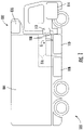
- FIG. 1 a partial view of an exemplary embodiment of a transportation refrigeration system in accordance with the disclosure is shown in FIG. 1 and is designated generally by reference character 100.
- FIG. 1 a partial view of an exemplary embodiment of a transportation refrigeration system in accordance with the disclosure is shown in FIG. 1 and is designated generally by reference character 100.
- Other embodiments of transportation refrigeration systems, methods of controlling gas flow in transportation refrigeration systems, and computer program products for controlling gas flow in transportation refrigeration units in accordance with the present disclosure, or aspects thereof, are provided in Figs. 2-4 , as will be described.
- the systems and methods described herein can be used for monitoring the health of electric lock-off valves in split bottle gas supplies for transportation refrigeration systems, such as four (4) bottle compressed natural gas (CNG) gas supplies carried by vehicles, though the present disclosure is not limited to systems having four gas bottles or to transportation refrigeration systems carried by any specific type of vehicle in general.
- CNG compressed natural gas
- Transportation refrigeration system 100 includes a transportation refrigeration unit (TRU) 102, a cold box 104, and a TRU gas engine 106.
- Transportation refrigeration system 100 also includes a split bottle gas supply 108, a main bottle 110, a gas filling box 112, and a prime mover gas engine 114.
- Transportation refrigeration system 100 additionally includes a first gas circuit 116 and a second gas circuit 118.
- the TRU gas engine 106 is operably associated with the TRU 102 and provides mechanical power for one or more refrigeration component of the TRU 102.
- TRU 102 in turn includes a plurality of refrigeration components arranged in a refrigeration circuit and operating according to a refrigeration cycle to cool an associated conditioned space 10 (shown in FIG. 2 ) refrigerated space located within cold box 104.
- the refrigeration circuit includes a compressor, a condenser, an expansion valve, and an evaporator interconnected to one another by working fluid conduit segments.
- the refrigeration circuit can be, for example, as described as described in U.S. Patent Application No. 2011/0030399 A1, published February 10, 2011 .
- the main bottle 110 is configured and adapted for providing a flow of compressed gas to the prime mover gas engine 114.
- the main bottle 110 is connected to the prime mover gas engine 114 by the second gas circuit 118, which can be an original equipment manufacturer (OEM) gas circuit provided with the vehicle carrying TRU 102.
- the main bottle 110 is also connected to the gas filling box 112 for receiving therethrough a charge of compressed gas G.
- the compressed gas G is natural gas.
- the compressed gas is propane. It is also contemplated that, in accordance with certain embodiments, the compressed gas G can be hydrogen gas.
- the first gas circuit 116 is configured and adapted for providing a flow of compressed gas to the TRU gas engine 106.
- the first gas circuit 116 connects the gas filling box 112 to bottles of the split bottle gas supply 108.
- the first gas circuit 116 also connects the split bottle gas supply 108 to the TRU gas engine 106. It is contemplated that, in accordance with certain embodiments, the first gas circuit 116 convey the same compressed gas, i.e., compressed gas G, as that conveyed by the second gas circuit 118.
- first gas circuit 116 and the second gas circuit 118 can be in fluid communication with one another as well as with a fill port located in the gas filling box 112 for charging both the split bottle gas supply 108 and the main bottle 110 with compressed gas G from the gas filling box 112.
- first gas circuit 116 can be added with TRU 102 as a modification or retrofit kit, for example, to convert a generic vehicle equipped with a gas engine into a specialized transportation refrigeration system for use in a cold chain.
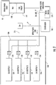
- split bottle gas supply 108 is shown.
- split bottle gas supply 108 is a four (4) bottle supply having four gas bottles configured for retaining a charge of compressed gas and four (4) electric lock-off valves connecting respective bottles to the first gas circuit 116.
- the split bottle gas supply 108 includes a first gas bottle 120, a second gas bottle 122, a third gas bottle 124, and a fourth gas bottle 126.
- the split bottle gas supply 108 additionally has a first electric lock-off valve 128, a second electric lock-off valve 130, a third electric lock-off valve 132, and a fourth electric lock-off valve 134.
- the present disclosure can be benefit transportation refrigeration systems having fewer than four bottles and more than four bottles, as suitable for an intended application.
- the first electric lock-off valve 126 connects the first gas bottle 120 to the first gas circuit 116 through a gas manifold 136.
- the second electric lock-off valve 128 connects the second gas bottle 124 to the first gas circuit 116 through the gas manifold 136
- the third electric lock-off valve 130 connects the third gas bottle 124 to the first gas circuit 116 through the gas manifold 136
- the fourth electric lock-off valve 134 connects the fourth gas bottle 126 to the first gas circuit 116 through the gas manifold 136.
- the gas manifold 136 in turn is in communication with the first gas circuit 116, and therethrough with the TRU gas engine 106, and a pressure sensor 138.
- the pressure sensor 138 is configured and adapted to provide measurement of gas pressure within the first gas circuit 116.
- the gas pressure within the first gas circuit 116 is in turn influenced by (or is equivalent to) the average of the pressure of the gas bottles in fluid communication with the first gas circuit 116.
- the electric lock-off valves 128-134 can include solenoid-driven valve members that move between open and closed positions according to whether the solenoid is energized or de-energized.
- electric lock-off valves 128-134 are configured such that the respective electric lock-off valve is closed when no current is applied to the solenoid.
- electric lock-off valves of having different arrangements can also benefit from the present disclosure.
- electric lock-off valves employed by split bottle gas supplies can sometimes function abnormally.
- one or more of the electric lock-off valves employed by a split bottle gas supply can remain open when commanded to close, remain closed when commanded to open, and/or remain partially open when commanded to open or close, potentially reducing the reliability of the transportation refrigeration system supplied by the split bottle gas supply.
- TRU 102 includes a controller 140, which is configured and adapted for determining health of each of electric lock-off valves 128-134.
- the controller 140 includes a processor 142, a device interface 144, a user interface 146, and a memory 148.
- the processor 142 is disposed in communication with the device interface 144, the user interface 146, and the memory 148 through an internal link 150.
- the user interface 146 is configured and adapted for providing information to a user and/or receiving input from a user.
- the device interface 144 is disposed in communication through an external link 152 with the pressure sensor 138 and the electric lock-off valves 128-134, the processor 142 thereby being disposed in communication with the pressure sensor 138 and operatively connected to the electric lock-off valves 128-134.
- the processor 142 is additionally disposed in communication with a filling box door switch 154 through the device interface 144, which provides therethrough to controller indication of completion of gas bottle filling event.
- the memory 148 has a plurality of program modules 158 recorded on it that, when read by the processor 142, cause the controller 140 to execute certain operations. Among those operations are the operations of a method 200 (shown in FIG. 4 ) of determining health of electric lock-off valves in a split bottle gas supply, as will be described.
- the memory 148 includes a computer program product 160 tangibly embodied thereon that, when executed by the processor 142, cause the processor 142 (and thereby the controller 140) to close the electric lock-off valves 128-134 (shown in FIG. 2 ) of the split bottle gas supply 108 and receive a first measurement of gas pressure in the first gas circuit 116 connected to the split bottle gas supply 108.
- the first electric lock-off valve 128 of the split bottle gas supply 108 is then opened, a second measurement of gas pressure in the first gas circuit 116 is received, and determination of health of the first electric lock-off valve 128 made using the first and second measurements of gas pressure in the first gas circuit 116. It is contemplated that health of each of the electric lock-off valves 128-134 be determined sequentially by repeating these operations for electric lock-off valves 130-134 subsequent to determining the health of the first electric lock-off valve 128.
- TRU 102 includes four (4) relays, i.e. relays 128R-134R. Each of the four relays is disposed in communication with the controller 140 and is in operative association with one of the four (4) electric lock-off valves of the split bottle gas supply 108. It is contemplated that, in certain embodiments, that TRU 102 include a single relay for association with each of the electric lock-off valves, the single relay providing independent actuation of the associated electric lock-off valve.
- this provides the capability to place a singular gas bottle in communication with the singular pressure sensor, in isolation from the other gas bottles, thereby allowing for assessment of the operation of the electric lock-off valve associated with the gas bottle.
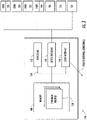
- method 200 of determining health of electric lock-off valves in a split bottle gas supply e.g., split bottle gas supply 108 (shown in FIG. 2 ) is shown.
- the method 200 includes, at a TRU such as the TRU 100 (shown in FIG. 1 ), closing the electric lock-off valves of the split bottle gas supply, e.g., the electric lock-off valves 128-134 (shown in FIG. 2 ), as shown with box 210.
- a first measurement of gas pressure in a gas circuit e.g., the first gas circuit 116 (shown in FIG. 1 ), as shown with box 220.
- a first of the electric lock-off valves of the split bottle gas supply is opened, e.g., the first electric lock-off valve 128 (shown in FIG. 2 ), as shown with box 230, and a second measurement of gas pressure in the gas circuit received, as shown with box 240.
- Health of the first electric lock-off valve is determined using the first and second measurements of gas pressure in the gas circuit, as shown with box 250.
- health of the electric lock-off can be determined by calculating the difference between the first gas pressure measurement and the second gas pressure measurement, as shown with box 252.
- the difference between the second gas pressure measurement and the first gas pressure measurement is above a predetermined value the operation of the electric lock-off valve is determined to be normal, as shown with box 254.
- the difference between the second gas pressure measurement and the first gas pressure measurement is below the predetermined value the operation of the electric lock off valve is determined to be abnormal, as shown with box 256.
- the health determination can thereafter be displayed on a user interface, e.g., the user interface 146 (shown in FIG. 3 ).
- a user interface e.g., the user interface 146 (shown in FIG. 3 ).
- displaying the health determination for each electric lock-off valve can improve reliability of the transportation refrigeration as abnormal operation can be detected more rapidly, and in certain embodiments automatically in association with gas fill events, during routine operation of the transportation refrigeration system.
- the health can be sequentially determined for each of the electric lock-off valves of the split bottle gas system, as shown with box 262 and arrow 264.
- each of the electric lock-off valves can again be commanded closed, a first measurement of gas pressure acquired, another of the electric lock off valves 130-134 opened, and a second measurement of pressure received for determining health of the another of the electric lock-off valves. It is contemplated that the method 200 continue iteratively until determination of health of each of the electric lock-off valves of the split bottle gas supply is made.
- method 200 can be automatically initiated.
- a gas fill event can be detected by detection of displacement of a gas filling box during the filling operation.
- a door switch e.g., the door switch 154 (shown in FIG. 2 )
- the electric lock valves can then be closed subsequent to the closure of the door on the gas filling box, as shown with box 212.
- this allows the first gas pressure measurement to be substantially equivalent of the fill pressure applied to gas bottles of the split bottle gas supply.
- a gas engine connected to the split bottle gas supply can be started, e.g., TRU gas engine 106 (shown in FIG. 1 ), prior to closure of the first electric lock-off valve and acquisition of the second gas pressure measurement such that ability of the electric lock-off valve to close is tested, as shown with boxes 280 and 290.
- TRU gas engine 106 shown in FIG. 1
Landscapes
- Engineering & Computer Science (AREA)
- Mechanical Engineering (AREA)
- General Engineering & Computer Science (AREA)
- Devices That Are Associated With Refrigeration Equipment (AREA)
- Filling Or Discharging Of Gas Storage Vessels (AREA)
Claims (13)
- Transportkühlsystem (100), das Folgendes umfasst:eine Transportkühleinheit (102);eine Kühlbox (104);einen Transportkühleinheit-Gasmotor (106);einen Gaskreislauf (116, 118), der mit der Transportkühleinheit (102) verbunden und dazu eingerichtet ist, daran eine geteilte Flaschengasversorgung (108), die eine Vielzahl elektrischer Absperrventile aufweist, anzuschließen; undeinen Controller (140), der mit der Transportkühleinheit (102) betriebsmäßig verbunden ist;einen Drucksensor (138), der dazu eingerichtet ist, den Gasdruck in dem Gaskreislauf (116, 118) zu messen und der in Kommunikation mit dem Controller (140) ist; undwobei der Controller (140) auf Anweisungen reagiert, die in einem Speicher aufgezeichnet sind, um:die elektrischen Absperrventile der geteilten Gasflaschenversorgung (108) zu schließen;eine erste Messung des Gasdrucks in dem Gaskreislauf (116, 118) zu empfangen;ein erstes der elektrischen Absperrventile der geteilten Gasflaschenversorgung (108) zu öffnen;den Gasmotor (106) nach dem Öffnen des ersten elektrischen Absperrventils zu starten;das erste elektrische Absperrventil (128) zu schließen;eine zweite Messung des Gasdrucks in dem Gaskreislauf (116, 118) zu empfangen; unddie Funktionstüchtigkeit des ersten elektrischen Absperrventils (128) unter Verwendung der ersten und der zweiten Messung des Gasdrucks in dem Gaskreislauf (116, 118) zu bestimmen.
- System (100) nach einem der vorstehenden Ansprüche, wobei die Anweisungen den Controller (140) veranlassen:eine Differenz zwischen der ersten Messung und der zweiten Messung des Gasdrucks in dem Gaskreislauf (116, 118) zu berechnen;zu bestimmen, dass das erste elektrische Absperrventil normal arbeitet, wenn die Differenz größer als ein vorbestimmter Wert ist; undzu bestimmen, dass das erste elektrische Absperrventil nicht normal arbeitet, wenn die Differenz innerhalb des vorbestimmten Werts liegt.
- System (100) nach einem der vorstehenden Ansprüche, wobei die Anweisungen den Controller (140) veranlassen, die Funktionstüchtigkeit jedes der elektrischen Absperrventile in der geteilten Gasflaschenversorgung (108) nach dem Bestimmen der Funktionstüchtigkeit des ersten elektrischen Absperrventils sequenziell zu bestimmen.
- System (100) nach einem der vorstehenden Ansprüche, das ferner eine Benutzeroberfläche (146) umfasst, die mit dem Controller (140) betriebsmäßig verbunden ist, wobei die Anweisungen den Controller (140) veranlassen, die bestimmte Funktionstüchtigkeit des ersten Absperrventils auf der Benutzeroberfläche (146) anzuzeigen.
- System (100) nach einem der vorstehenden Ansprüche, wobei die Anweisungen den Controller (140) veranlassen, die elektrischen Absperrventile zu schließen, nach dem Erhalten eines Hinweises, dass die Gasversorgung (108) der geteilten Gasflasche bei einem Befüllungsvorgang geladen wurde.
- System (100) nach einem der vorstehenden Ansprüche,das ferner Folgendes umfassteinen Türschalter (154), der in Kommunikation mit dem Controller (140) angeordnet und zum Erfassen einer Verlagerung der Gasbefüllungskastentür während eines Befüllungsvorgangs eingerichtet ist.
- System (100) nach einem der vorstehenden Ansprüche, wobei der Gaskreislauf (116, 118) ein erster Gaskreislauf (116) ist und ferner einen zweiten Gaskreislauf (118), der mit dem ersten Gaskreislauf (116) verbunden ist, umfasst.
- System (100) nach einem der vorstehenden Ansprüche, das ferner Folgendes umfasst:eine geteilte Flaschengasversorgung (108), die mit dem Gasmotor (106) der Transportkühleinheit durch den ersten Gaskreislauf (116) verbunden ist;einen Gasbefüllungskasten (112), der durch den ersten Gaskreislauf (116) mit der geteilten Gasflaschenversorgung (108) verbunden ist;einen zweiten Gaskreislauf (118), der mit dem Gasbefüllungskasten (112) verbunden ist;eine Hauptgasflasche, die durch den zweiten Gaskreislauf (118) mit dem Gasbefüllungskasten (112) verbunden ist; undeinen Antriebsgasmotor, der durch den zweiten Gaskreislauf (118) mit der Hauptgasflasche verbunden ist.
- System (100) nach einem der vorstehenden Ansprüche, das ferner eine geteilte Gasflaschenversorgung (108) umfasst, die mit dem Gaskreislauf (116, 118) verbunden ist, wobei die geteilte Gasflaschenversorgung (108) Folgendes umfasst:einen Verteiler (136), der mit dem Drucksensor (138) verbunden ist;eine erste Gasflasche (120) mit einem ersten elektrischen Absperrventil (128), das mit dem Verteiler (136) verbunden ist, ein erstes Relais, das dem ersten elektrischen Absperrventil (128) betriebsmäßig zugeordnet ist; undmindestens eine zweite Gasflasche (122) mit einem zweiten elektrischen Absperrventil (130), das mit dem Verteiler (136) verbunden ist, wobei ein Relais jedem des einen zweiten elektrischen Absperrventils (122) betriebsmäßig zugeordnet ist,wobei der Controller (140) in Kommunikation mit dem Drucksensor (138) angeordnet ist, um Druckmessungen davon zu empfangen, undwobei der Controller (140) betriebsmäßig mit dem ersten elektrischen Absperrventil (128) und dem zweiten elektrischen Absperrventil (122) durch das damit zugeordnete Relais verbunden ist, um die Gasflasche, die mit dem Absperrventil verbunden ist, von dem Drucksensor (138) zu isolieren.
- Verfahren zum Bestimmen der Funktionstüchtigkeit elektrischer Absperrventile in einer geteilten Flaschengasversorgung (108), wobei das Verfahren Folgendes umfasst:bei einem Transportkühlsystem (100) enthaltend eine Transportkühleinheit (102), eine Kühlbox (104); einen Transportkühleinheit-Gasmotor (106); einen Gaskreislauf (116, 118), der mit der Transportkühleinheit (102) verbunden und dazu eingerichtet ist, daran eine geteilte Flaschengasversorgung (108) anzuschließen, die eine Vielzahl elektrischer Absperrventile aufweist, und einen Controller (140), der mit der Transportkühleinheit (102) betriebsmäßig verbunden ist,Schließen der elektrischen Absperrventile der geteilten Gasflaschenversorgung (108);Empfangen einer ersten Messung des Gasdrucks in dem Gaskreislauf (116, 118);Öffnen eines ersten der elektrischen Absperrventile der geteilten Gasflaschenversorgung (108);Starten des Gasmotors (106) nach dem Öffnen des ersten elektrischen Absperrventils (128); undSchließen des ersten elektrischen Absperrventils (128), bevor die zweite Messung des Gasdrucks in dem Gaskreislauf (116, 118) empfangen wird;Empfangen einer zweiten Messung des Gasdrucks in dem Gaskreislauf (116, 118); undBestimmen der Funktionstüchtigkeit des ersten elektrischen Absperrventils (128) unter Verwendung der ersten und der zweiten Messung des Gasdrucks in dem Gaskreislauf (116, 118).
- Verfahren nach Anspruch 10, das ferner Folgendes umfasst:Anzeigen der Funktionstüchtigkeit des ersten elektrischen Absperrventils (128) auf einer Benutzeroberfläche (146); und/oderBerechnen einer Differenz zwischen der ersten Messung und der zweiten Messung des Gasdrucks in dem Gaskreislauf (116, 118);Bestimmen, dass das erste elektrische Absperrventil (128) normal arbeitet, wenn die Differenz größer als ein vorbestimmter Wert ist; undBestimmen, dass das erste elektrische Absperrventil (128) nicht normal arbeitet, wenn die Differenz innerhalb des vorbestimmten Werts liegt;
und/odersequenzielles Bestimmen der Funktionstüchtigkeit jedes der elektrischen Absperrventile in der geteilten Gasflaschenversorgung (108) nach dem Bestimmen der Funktionstüchtigkeit des ersten elektrischen Absperrventils (128);
und/oderErfassen einer Verlagerung der Gasbefüllungskastentür während eines Befüllungsvorgangs; undSchließen der elektrischen Absperrventile nach Erhalt eines Hinweises, dass die geteilte Flaschengasversorgung (108) während des Befüllungsvorgangs geladen wurde. - Computerprogrammprodukt, das konkret auf einem computerlesbaren Medium verkörpert ist, wobei das Computerprogrammprodukt Anweisungen beinhaltet, die, wenn sie von einem Prozessor ausgeführt werden, den Prozessor veranlassen, Vorgänge durchzuführen, die Folgendes umfassen:Schließen elektrischer Absperrventile einer geteilten Gasflaschenversorgung (108);Empfangen einer ersten Messung des Gasdrucks in einem Gaskreislauf (116, 118), der mit der geteilten Gasflaschenversorgung (108) verbunden ist;Öffnen eines ersten der elektrischen Absperrventile der geteilten Gasflaschenversorgung (108);Starten des Gasmotors (106) nach dem Öffnen des ersten elektrischen Absperrventils (128); undSchließen des ersten elektrischen Absperrventils (128), bevor die zweite Messung des Gasdrucks in dem Gaskreislauf (116, 118) empfangen wird;Empfangen einer zweiten Messung des Gasdrucks in dem Gaskreislauf (116, 118); undBestimmen der Funktionstüchtigkeit des ersten elektrischen Absperrventils (128) unter Verwendung der ersten und der zweiten Messung des Gasdrucks in dem Gaskreislauf (108).
- Computerprogrammprodukt nach Anspruch 12,wobei die Vorgänge fernerdas sequenzielle Bestimmen der Funktionstüchtigkeit jedes der elektrischen Absperrventile in der geteilten Gasflaschenversorgung (108) nach dem Bestimmen der Funktionstüchtigkeit des ersten elektrischen Absperrventils (128) umfassen.
Priority Applications (4)
| Application Number | Priority Date | Filing Date | Title |
|---|---|---|---|
| EP18306625.7A EP3663633B1 (de) | 2018-12-06 | 2018-12-06 | Systeme und verfahren zur steuerung des gasdurchflusses in transportkälteanlagen |
| PCT/US2019/064637 WO2020118024A1 (en) | 2018-12-06 | 2019-12-05 | Systems and methods for controlling gas flow in transportation refrigeration systems |
| CN201980041593.7A CN112400080B (zh) | 2018-12-06 | 2019-12-05 | 用于控制运输制冷系统中的气流的系统和方法 |
| US16/973,680 US11306875B2 (en) | 2018-12-06 | 2019-12-05 | Systems and methods for controlling gas flow in transportation refrigeration systems |
Applications Claiming Priority (1)
| Application Number | Priority Date | Filing Date | Title |
|---|---|---|---|
| EP18306625.7A EP3663633B1 (de) | 2018-12-06 | 2018-12-06 | Systeme und verfahren zur steuerung des gasdurchflusses in transportkälteanlagen |
Publications (2)
| Publication Number | Publication Date |
|---|---|
| EP3663633A1 EP3663633A1 (de) | 2020-06-10 |
| EP3663633B1 true EP3663633B1 (de) | 2022-09-07 |
Family
ID=64665797
Family Applications (1)
| Application Number | Title | Priority Date | Filing Date |
|---|---|---|---|
| EP18306625.7A Active EP3663633B1 (de) | 2018-12-06 | 2018-12-06 | Systeme und verfahren zur steuerung des gasdurchflusses in transportkälteanlagen |
Country Status (4)
| Country | Link |
|---|---|
| US (1) | US11306875B2 (de) |
| EP (1) | EP3663633B1 (de) |
| CN (1) | CN112400080B (de) |
| WO (1) | WO2020118024A1 (de) |
Families Citing this family (3)
| Publication number | Priority date | Publication date | Assignee | Title |
|---|---|---|---|---|
| DE102022201956A1 (de) * | 2022-02-25 | 2023-08-31 | Robert Bosch Gesellschaft mit beschränkter Haftung | Verfahren zum Betreiben eines Druckgastanksystems sowie Steuergerät |
| DE102023207801A1 (de) * | 2023-08-14 | 2025-02-20 | Robert Bosch Gesellschaft mit beschränkter Haftung | Diagnoseverfahren zur Diagnose eines Zustands eines Tankventils, Tanksystem und Programmprodukt |
| DE102024200112A1 (de) * | 2024-01-05 | 2025-07-10 | Robert Bosch Gesellschaft mit beschränkter Haftung | Verfahren zum Steuern eines sich im Betrieb befindlichen Tanksystems, Tanksystem, Computerprogrammprodukt und computerlesbares Medium |
Family Cites Families (33)
| Publication number | Priority date | Publication date | Assignee | Title |
|---|---|---|---|---|
| US4527600A (en) * | 1982-05-05 | 1985-07-09 | Rockwell International Corporation | Compressed natural gas dispensing system |
| CN101488577B (zh) * | 2003-07-25 | 2011-06-08 | 丰田自动车株式会社 | 气体供给装置 |
| WO2005010427A1 (ja) * | 2003-07-25 | 2005-02-03 | Toyota Jidosha Kabushiki Kaisha | ガス供給装置 |
| EP2203675B1 (de) | 2007-03-02 | 2020-04-08 | ezNG Solutions, LLC | Speicherung, transport und gebrauch von verdichteten fluiden |
| US20110030399A1 (en) | 2008-01-08 | 2011-02-10 | Carrier Corporation | Refrigerant system with fuel cell for electricity generation |
| US20090294470A1 (en) | 2008-05-27 | 2009-12-03 | Neogas Inc. | Variable Frequency Drive for Gas Dispensing System |
| US10780955B2 (en) | 2008-06-20 | 2020-09-22 | Seaone Holdings, Llc | Comprehensive system for the storage and transportation of natural gas in a light hydrocarbon liquid medium |
| TR200809620A2 (tr) | 2008-12-18 | 2010-07-21 | Aygaz Anon�M ��Rket� | LPG tüpleri için bir kaçak kontrol mekanizması |
| GB2472860A (en) * | 2009-08-21 | 2011-02-23 | Gm Global Tech Operations Inc | Method of detecting at least one malfunctioning high-pressure gas tank |
| US20110140850A1 (en) | 2009-12-16 | 2011-06-16 | Matheson Tri-Gas, Inc. | Real time tracking and monitoring of gas cylinders |
| CN101865754B (zh) * | 2010-07-20 | 2012-11-21 | 哈尔滨工业大学 | 一种复合材料层合板气密性检测方法 |
| BR112013009092B1 (pt) | 2010-10-12 | 2021-07-06 | Seaone Ag | processo para misturar gás natural com um solvente de hidrocarboneto que facilitem razões volumétricas melhoradas do gás natural armazenado |
| US8100076B1 (en) | 2011-02-11 | 2012-01-24 | Atp Oil & Gas Corporation | Liquefied natural gas processing and transport system |
| US8899278B2 (en) * | 2011-06-17 | 2014-12-02 | Air Products And Chemicals, Inc. | Pressure cycle management in compressed gas dispensing systems |
| EP2589780A1 (de) * | 2011-11-04 | 2013-05-08 | Caterpillar Motoren GmbH & Co. KG | Brennstoffversorgungssystem mit Leckerkennungsmitteln |
| EA029810B1 (ru) | 2011-12-05 | 2018-05-31 | Блю Вэйв Ко С.А. | Резервуар для работы под высоким давлением с композитным штуцером, имеющим защиту от электрохимической коррозии |
| US9238865B2 (en) * | 2012-02-06 | 2016-01-19 | Asm Ip Holding B.V. | Multiple vapor sources for vapor deposition |
| US9284895B2 (en) | 2012-10-23 | 2016-03-15 | Fca Ua Llc | Methods and apparatuses for diagnosing leaks in a compressed natural gas delivery system |
| AU2013362826B2 (en) | 2012-12-20 | 2017-01-05 | Mosaic Technology Development Pty Ltd | System and method for refuelling a compressed gas pressure vessel using a thermally coupled nozzle |
| US9074730B2 (en) * | 2013-03-14 | 2015-07-07 | Air Products And Chemicals, Inc. | Method for dispensing compressed gases |
| US9279541B2 (en) * | 2013-04-22 | 2016-03-08 | Air Products And Chemicals, Inc. | Method and system for temperature-controlled gas dispensing |
| US9598946B2 (en) | 2013-07-08 | 2017-03-21 | Ronald Grant Shomody | Processing and transport of stranded gas to conserve resources and reduce emissions |
| AU2014312438B2 (en) | 2013-08-28 | 2018-09-13 | Nuvera Fuel Cells, LLC | Integrated electrochemical compressor and cascade storage method and system |
| US9454856B2 (en) * | 2014-01-21 | 2016-09-27 | GM Global Technology Operations LLC | Liquefied petroleum gas tank leak detection systems and methods |
| MX394294B (es) | 2014-10-06 | 2025-03-24 | Mes Life Safety Llc | Sistema y método para llenar automáticamente cilindros de fluido. |
| DE102014019419A1 (de) * | 2014-12-22 | 2016-06-23 | GM Global Technology Operations LLC (n. d. Ges. d. Staates Delaware) | Verfahren und Diagnoseeinrichtung zur Überprüfung von Hochdrucktankventilen, Hochdrucktanksystem und Kraftfahrzeug mit einem Hochdrucktanksystem |
| US9784411B2 (en) | 2015-04-02 | 2017-10-10 | David A. Diggins | System and method for unloading compressed natural gas |
| US10508771B2 (en) | 2016-03-30 | 2019-12-17 | Praxair Technology, Inc. | Method and system for optimizing the filling, storage and dispensing of carbon dioxide from multiple containers without overpressurization |
| US20190360433A1 (en) | 2016-05-03 | 2019-11-28 | Carrier Corporation | Integrated compressed gas transport refrigeration unit for compressed gas fueled vehicles |
| EP3465034B1 (de) * | 2016-05-27 | 2022-02-16 | Carrier Corporation | Mehrbrennstofftransportkühleinheit und verfahren zu ihrem betrieb |
| ES2913996T3 (es) | 2016-05-30 | 2022-06-07 | Carrier Corp | Llenado de punto único para una unidad de refrigeración independiente impulsada por un motor separado |
| US10228188B2 (en) * | 2016-06-09 | 2019-03-12 | Maersk Container Industry A/S | Method for real-time performance check of container system |
| SE540146C2 (en) * | 2016-06-21 | 2018-04-10 | Scania Cv Ab | Method for determining the proper operation of a valve in a gas tank system |
-
2018
- 2018-12-06 EP EP18306625.7A patent/EP3663633B1/de active Active
-
2019
- 2019-12-05 CN CN201980041593.7A patent/CN112400080B/zh active Active
- 2019-12-05 US US16/973,680 patent/US11306875B2/en active Active
- 2019-12-05 WO PCT/US2019/064637 patent/WO2020118024A1/en not_active Ceased
Also Published As
| Publication number | Publication date |
|---|---|
| CN112400080B (zh) | 2024-02-09 |
| WO2020118024A1 (en) | 2020-06-11 |
| EP3663633A1 (de) | 2020-06-10 |
| CN112400080A (zh) | 2021-02-23 |
| US11306875B2 (en) | 2022-04-19 |
| US20210293386A1 (en) | 2021-09-23 |
Similar Documents
| Publication | Publication Date | Title |
|---|---|---|
| EP2782851B1 (de) | Verfahren zur betriebserprobung eines klimaregelungssystems für einen container | |
| EP3265966B1 (de) | Verfahren und system zur steuerung von kühlcontainerressourcen | |
| US4060400A (en) | Refrigerated semitrailer truck for long and local deliveries | |
| US11306875B2 (en) | Systems and methods for controlling gas flow in transportation refrigeration systems | |
| EP2812640B1 (de) | Verfahren zur erfassung von kältemittelverlust | |
| US11441820B2 (en) | Refrigerant leak detection system | |
| US11287163B2 (en) | Fuel leak detection in a gaseous fueled transportation refrigeration unit | |
| CN113631879A (zh) | 冷藏货物监控 | |
| CN111212971B (zh) | 用于运输制冷单元的天然气箱压力控制 | |
| CN105431693B (zh) | 用于制冷系统的制冷剂液位监控 | |
| Złoczowska | Maritime containers refrigeration plant faults survey | |
| US12498155B2 (en) | Transportation refrigeration unit and method of measuring quantity of refrigerant in the same | |
| CN111936805A (zh) | 对制冷系统除霜的方法 | |
| BR102018006699A2 (pt) | Dispositivo autônomo de monitoramento remoto de contêineres refrigerados e processo de monitoramento |
Legal Events
| Date | Code | Title | Description |
|---|---|---|---|
| PUAI | Public reference made under article 153(3) epc to a published international application that has entered the european phase |
Free format text: ORIGINAL CODE: 0009012 |
|
| STAA | Information on the status of an ep patent application or granted ep patent |
Free format text: STATUS: REQUEST FOR EXAMINATION WAS MADE |
|
| 17P | Request for examination filed |
Effective date: 20200427 |
|
| AK | Designated contracting states |
Kind code of ref document: A1 Designated state(s): AL AT BE BG CH CY CZ DE DK EE ES FI FR GB GR HR HU IE IS IT LI LT LU LV MC MK MT NL NO PL PT RO RS SE SI SK SM TR |
|
| AX | Request for extension of the european patent |
Extension state: BA ME |
|
| GRAP | Despatch of communication of intention to grant a patent |
Free format text: ORIGINAL CODE: EPIDOSNIGR1 |
|
| STAA | Information on the status of an ep patent application or granted ep patent |
Free format text: STATUS: GRANT OF PATENT IS INTENDED |
|
| INTG | Intention to grant announced |
Effective date: 20220318 |
|
| GRAS | Grant fee paid |
Free format text: ORIGINAL CODE: EPIDOSNIGR3 |
|
| GRAA | (expected) grant |
Free format text: ORIGINAL CODE: 0009210 |
|
| STAA | Information on the status of an ep patent application or granted ep patent |
Free format text: STATUS: THE PATENT HAS BEEN GRANTED |
|
| AK | Designated contracting states |
Kind code of ref document: B1 Designated state(s): AL AT BE BG CH CY CZ DE DK EE ES FI FR GB GR HR HU IE IS IT LI LT LU LV MC MK MT NL NO PL PT RO RS SE SI SK SM TR |
|
| REG | Reference to a national code |
Ref country code: GB Ref legal event code: FG4D |
|
| REG | Reference to a national code |
Ref country code: CH Ref legal event code: EP Ref country code: AT Ref legal event code: REF Ref document number: 1517325 Country of ref document: AT Kind code of ref document: T Effective date: 20220915 |
|
| REG | Reference to a national code |
Ref country code: IE Ref legal event code: FG4D |
|
| REG | Reference to a national code |
Ref country code: DE Ref legal event code: R096 Ref document number: 602018040286 Country of ref document: DE |
|
| REG | Reference to a national code |
Ref country code: LT Ref legal event code: MG9D |
|
| REG | Reference to a national code |
Ref country code: NL Ref legal event code: MP Effective date: 20220907 |
|
| PG25 | Lapsed in a contracting state [announced via postgrant information from national office to epo] |
Ref country code: SE Free format text: LAPSE BECAUSE OF FAILURE TO SUBMIT A TRANSLATION OF THE DESCRIPTION OR TO PAY THE FEE WITHIN THE PRESCRIBED TIME-LIMIT Effective date: 20220907 Ref country code: RS Free format text: LAPSE BECAUSE OF FAILURE TO SUBMIT A TRANSLATION OF THE DESCRIPTION OR TO PAY THE FEE WITHIN THE PRESCRIBED TIME-LIMIT Effective date: 20220907 Ref country code: NO Free format text: LAPSE BECAUSE OF FAILURE TO SUBMIT A TRANSLATION OF THE DESCRIPTION OR TO PAY THE FEE WITHIN THE PRESCRIBED TIME-LIMIT Effective date: 20221207 Ref country code: LV Free format text: LAPSE BECAUSE OF FAILURE TO SUBMIT A TRANSLATION OF THE DESCRIPTION OR TO PAY THE FEE WITHIN THE PRESCRIBED TIME-LIMIT Effective date: 20220907 Ref country code: LT Free format text: LAPSE BECAUSE OF FAILURE TO SUBMIT A TRANSLATION OF THE DESCRIPTION OR TO PAY THE FEE WITHIN THE PRESCRIBED TIME-LIMIT Effective date: 20220907 Ref country code: FI Free format text: LAPSE BECAUSE OF FAILURE TO SUBMIT A TRANSLATION OF THE DESCRIPTION OR TO PAY THE FEE WITHIN THE PRESCRIBED TIME-LIMIT Effective date: 20220907 |
|
| REG | Reference to a national code |
Ref country code: AT Ref legal event code: MK05 Ref document number: 1517325 Country of ref document: AT Kind code of ref document: T Effective date: 20220907 |
|
| PG25 | Lapsed in a contracting state [announced via postgrant information from national office to epo] |
Ref country code: HR Free format text: LAPSE BECAUSE OF FAILURE TO SUBMIT A TRANSLATION OF THE DESCRIPTION OR TO PAY THE FEE WITHIN THE PRESCRIBED TIME-LIMIT Effective date: 20220907 Ref country code: GR Free format text: LAPSE BECAUSE OF FAILURE TO SUBMIT A TRANSLATION OF THE DESCRIPTION OR TO PAY THE FEE WITHIN THE PRESCRIBED TIME-LIMIT Effective date: 20221208 |
|
| PG25 | Lapsed in a contracting state [announced via postgrant information from national office to epo] |
Ref country code: SM Free format text: LAPSE BECAUSE OF FAILURE TO SUBMIT A TRANSLATION OF THE DESCRIPTION OR TO PAY THE FEE WITHIN THE PRESCRIBED TIME-LIMIT Effective date: 20220907 Ref country code: RO Free format text: LAPSE BECAUSE OF FAILURE TO SUBMIT A TRANSLATION OF THE DESCRIPTION OR TO PAY THE FEE WITHIN THE PRESCRIBED TIME-LIMIT Effective date: 20220907 Ref country code: PT Free format text: LAPSE BECAUSE OF FAILURE TO SUBMIT A TRANSLATION OF THE DESCRIPTION OR TO PAY THE FEE WITHIN THE PRESCRIBED TIME-LIMIT Effective date: 20230109 Ref country code: ES Free format text: LAPSE BECAUSE OF FAILURE TO SUBMIT A TRANSLATION OF THE DESCRIPTION OR TO PAY THE FEE WITHIN THE PRESCRIBED TIME-LIMIT Effective date: 20220907 Ref country code: CZ Free format text: LAPSE BECAUSE OF FAILURE TO SUBMIT A TRANSLATION OF THE DESCRIPTION OR TO PAY THE FEE WITHIN THE PRESCRIBED TIME-LIMIT Effective date: 20220907 Ref country code: AT Free format text: LAPSE BECAUSE OF FAILURE TO SUBMIT A TRANSLATION OF THE DESCRIPTION OR TO PAY THE FEE WITHIN THE PRESCRIBED TIME-LIMIT Effective date: 20220907 |
|
| PG25 | Lapsed in a contracting state [announced via postgrant information from national office to epo] |
Ref country code: SK Free format text: LAPSE BECAUSE OF FAILURE TO SUBMIT A TRANSLATION OF THE DESCRIPTION OR TO PAY THE FEE WITHIN THE PRESCRIBED TIME-LIMIT Effective date: 20220907 Ref country code: PL Free format text: LAPSE BECAUSE OF FAILURE TO SUBMIT A TRANSLATION OF THE DESCRIPTION OR TO PAY THE FEE WITHIN THE PRESCRIBED TIME-LIMIT Effective date: 20220907 Ref country code: IS Free format text: LAPSE BECAUSE OF FAILURE TO SUBMIT A TRANSLATION OF THE DESCRIPTION OR TO PAY THE FEE WITHIN THE PRESCRIBED TIME-LIMIT Effective date: 20230107 Ref country code: EE Free format text: LAPSE BECAUSE OF FAILURE TO SUBMIT A TRANSLATION OF THE DESCRIPTION OR TO PAY THE FEE WITHIN THE PRESCRIBED TIME-LIMIT Effective date: 20220907 |
|
| REG | Reference to a national code |
Ref country code: DE Ref legal event code: R097 Ref document number: 602018040286 Country of ref document: DE |
|
| PG25 | Lapsed in a contracting state [announced via postgrant information from national office to epo] |
Ref country code: NL Free format text: LAPSE BECAUSE OF FAILURE TO SUBMIT A TRANSLATION OF THE DESCRIPTION OR TO PAY THE FEE WITHIN THE PRESCRIBED TIME-LIMIT Effective date: 20220907 Ref country code: AL Free format text: LAPSE BECAUSE OF FAILURE TO SUBMIT A TRANSLATION OF THE DESCRIPTION OR TO PAY THE FEE WITHIN THE PRESCRIBED TIME-LIMIT Effective date: 20220907 |
|
| PLBE | No opposition filed within time limit |
Free format text: ORIGINAL CODE: 0009261 |
|
| STAA | Information on the status of an ep patent application or granted ep patent |
Free format text: STATUS: NO OPPOSITION FILED WITHIN TIME LIMIT |
|
| PG25 | Lapsed in a contracting state [announced via postgrant information from national office to epo] |
Ref country code: DK Free format text: LAPSE BECAUSE OF FAILURE TO SUBMIT A TRANSLATION OF THE DESCRIPTION OR TO PAY THE FEE WITHIN THE PRESCRIBED TIME-LIMIT Effective date: 20220907 |
|
| REG | Reference to a national code |
Ref country code: CH Ref legal event code: PL |
|
| 26N | No opposition filed |
Effective date: 20230608 |
|
| REG | Reference to a national code |
Ref country code: BE Ref legal event code: MM Effective date: 20221231 |
|
| PG25 | Lapsed in a contracting state [announced via postgrant information from national office to epo] |
Ref country code: SI Free format text: LAPSE BECAUSE OF FAILURE TO SUBMIT A TRANSLATION OF THE DESCRIPTION OR TO PAY THE FEE WITHIN THE PRESCRIBED TIME-LIMIT Effective date: 20220907 Ref country code: LU Free format text: LAPSE BECAUSE OF NON-PAYMENT OF DUE FEES Effective date: 20221206 |
|
| PG25 | Lapsed in a contracting state [announced via postgrant information from national office to epo] |
Ref country code: LI Free format text: LAPSE BECAUSE OF NON-PAYMENT OF DUE FEES Effective date: 20221231 Ref country code: IE Free format text: LAPSE BECAUSE OF NON-PAYMENT OF DUE FEES Effective date: 20221206 Ref country code: CH Free format text: LAPSE BECAUSE OF NON-PAYMENT OF DUE FEES Effective date: 20221231 |
|
| PG25 | Lapsed in a contracting state [announced via postgrant information from national office to epo] |
Ref country code: BE Free format text: LAPSE BECAUSE OF NON-PAYMENT OF DUE FEES Effective date: 20221231 |
|
| P01 | Opt-out of the competence of the unified patent court (upc) registered |
Effective date: 20240119 |
|
| PG25 | Lapsed in a contracting state [announced via postgrant information from national office to epo] |
Ref country code: HU Free format text: LAPSE BECAUSE OF FAILURE TO SUBMIT A TRANSLATION OF THE DESCRIPTION OR TO PAY THE FEE WITHIN THE PRESCRIBED TIME-LIMIT; INVALID AB INITIO Effective date: 20181206 |
|
| PG25 | Lapsed in a contracting state [announced via postgrant information from national office to epo] |
Ref country code: CY Free format text: LAPSE BECAUSE OF FAILURE TO SUBMIT A TRANSLATION OF THE DESCRIPTION OR TO PAY THE FEE WITHIN THE PRESCRIBED TIME-LIMIT Effective date: 20220907 |
|
| PG25 | Lapsed in a contracting state [announced via postgrant information from national office to epo] |
Ref country code: MK Free format text: LAPSE BECAUSE OF FAILURE TO SUBMIT A TRANSLATION OF THE DESCRIPTION OR TO PAY THE FEE WITHIN THE PRESCRIBED TIME-LIMIT Effective date: 20220907 Ref country code: IT Free format text: LAPSE BECAUSE OF FAILURE TO SUBMIT A TRANSLATION OF THE DESCRIPTION OR TO PAY THE FEE WITHIN THE PRESCRIBED TIME-LIMIT Effective date: 20220907 |
|
| PG25 | Lapsed in a contracting state [announced via postgrant information from national office to epo] |
Ref country code: MC Free format text: LAPSE BECAUSE OF FAILURE TO SUBMIT A TRANSLATION OF THE DESCRIPTION OR TO PAY THE FEE WITHIN THE PRESCRIBED TIME-LIMIT Effective date: 20220907 |
|
| PG25 | Lapsed in a contracting state [announced via postgrant information from national office to epo] |
Ref country code: TR Free format text: LAPSE BECAUSE OF FAILURE TO SUBMIT A TRANSLATION OF THE DESCRIPTION OR TO PAY THE FEE WITHIN THE PRESCRIBED TIME-LIMIT Effective date: 20220907 Ref country code: MC Free format text: LAPSE BECAUSE OF FAILURE TO SUBMIT A TRANSLATION OF THE DESCRIPTION OR TO PAY THE FEE WITHIN THE PRESCRIBED TIME-LIMIT Effective date: 20220907 |
|
| PG25 | Lapsed in a contracting state [announced via postgrant information from national office to epo] |
Ref country code: BG Free format text: LAPSE BECAUSE OF FAILURE TO SUBMIT A TRANSLATION OF THE DESCRIPTION OR TO PAY THE FEE WITHIN THE PRESCRIBED TIME-LIMIT Effective date: 20220907 |
|
| PG25 | Lapsed in a contracting state [announced via postgrant information from national office to epo] |
Ref country code: MT Free format text: LAPSE BECAUSE OF FAILURE TO SUBMIT A TRANSLATION OF THE DESCRIPTION OR TO PAY THE FEE WITHIN THE PRESCRIBED TIME-LIMIT Effective date: 20220907 |
|
| PGFP | Annual fee paid to national office [announced via postgrant information from national office to epo] |
Ref country code: DE Payment date: 20251126 Year of fee payment: 8 |
|
| PGFP | Annual fee paid to national office [announced via postgrant information from national office to epo] |
Ref country code: GB Payment date: 20251119 Year of fee payment: 8 |
|
| PGFP | Annual fee paid to national office [announced via postgrant information from national office to epo] |
Ref country code: FR Payment date: 20251120 Year of fee payment: 8 |