EP1821031A2 - Brennstoffzellenvorrichtungen und Verfahren dafür - Google Patents
Brennstoffzellenvorrichtungen und Verfahren dafür Download PDFInfo
- Publication number
- EP1821031A2 EP1821031A2 EP07102165A EP07102165A EP1821031A2 EP 1821031 A2 EP1821031 A2 EP 1821031A2 EP 07102165 A EP07102165 A EP 07102165A EP 07102165 A EP07102165 A EP 07102165A EP 1821031 A2 EP1821031 A2 EP 1821031A2
- Authority
- EP
- European Patent Office
- Prior art keywords
- fuel
- recited
- fuel cell
- cell device
- fuel cells
- Prior art date
- Legal status (The legal status is an assumption and is not a legal conclusion. Google has not performed a legal analysis and makes no representation as to the accuracy of the status listed.)
- Ceased
Links
- 239000000446 fuel Substances 0.000 title claims abstract description 228
- 238000000034 method Methods 0.000 title claims description 27
- UFHFLCQGNIYNRP-UHFFFAOYSA-N Hydrogen Chemical compound [H][H] UFHFLCQGNIYNRP-UHFFFAOYSA-N 0.000 claims description 11
- 239000003792 electrolyte Substances 0.000 claims description 11
- 239000003014 ion exchange membrane Substances 0.000 claims description 8
- 230000005611 electricity Effects 0.000 claims description 6
- 239000000463 material Substances 0.000 claims description 6
- 230000000007 visual effect Effects 0.000 claims description 6
- 238000004891 communication Methods 0.000 claims description 4
- 229910052987 metal hydride Inorganic materials 0.000 claims description 4
- 150000004681 metal hydrides Chemical class 0.000 claims description 4
- 230000008878 coupling Effects 0.000 claims 4
- 238000010168 coupling process Methods 0.000 claims 4
- 238000005859 coupling reaction Methods 0.000 claims 4
- 229920001690 polydopamine Polymers 0.000 abstract description 3
- OKKJLVBELUTLKV-UHFFFAOYSA-N Methanol Chemical compound OC OKKJLVBELUTLKV-UHFFFAOYSA-N 0.000 description 9
- 239000001257 hydrogen Substances 0.000 description 7
- 229910052739 hydrogen Inorganic materials 0.000 description 7
- 230000008569 process Effects 0.000 description 7
- 238000003487 electrochemical reaction Methods 0.000 description 6
- OKTJSMMVPCPJKN-UHFFFAOYSA-N Carbon Chemical compound [C] OKTJSMMVPCPJKN-UHFFFAOYSA-N 0.000 description 5
- 239000000376 reactant Substances 0.000 description 5
- 239000000758 substrate Substances 0.000 description 5
- 239000012528 membrane Substances 0.000 description 4
- 239000012080 ambient air Substances 0.000 description 3
- QVGXLLKOCUKJST-UHFFFAOYSA-N atomic oxygen Chemical compound [O] QVGXLLKOCUKJST-UHFFFAOYSA-N 0.000 description 3
- 230000004888 barrier function Effects 0.000 description 3
- 230000008901 benefit Effects 0.000 description 3
- 230000007423 decrease Effects 0.000 description 3
- 150000002500 ions Chemical class 0.000 description 3
- 230000007246 mechanism Effects 0.000 description 3
- 239000007800 oxidant agent Substances 0.000 description 3
- 230000001590 oxidative effect Effects 0.000 description 3
- 239000001301 oxygen Substances 0.000 description 3
- 229910052760 oxygen Inorganic materials 0.000 description 3
- 229910052799 carbon Inorganic materials 0.000 description 2
- 239000012530 fluid Substances 0.000 description 2
- 239000002737 fuel gas Substances 0.000 description 2
- 150000004678 hydrides Chemical class 0.000 description 2
- BDAGIHXWWSANSR-UHFFFAOYSA-N methanoic acid Natural products OC=O BDAGIHXWWSANSR-UHFFFAOYSA-N 0.000 description 2
- OSWFIVFLDKOXQC-UHFFFAOYSA-N 4-(3-methoxyphenyl)aniline Chemical compound COC1=CC=CC(C=2C=CC(N)=CC=2)=C1 OSWFIVFLDKOXQC-UHFFFAOYSA-N 0.000 description 1
- 239000001273 butane Substances 0.000 description 1
- 229910021393 carbon nanotube Inorganic materials 0.000 description 1
- 239000002041 carbon nanotube Substances 0.000 description 1
- 230000001413 cellular effect Effects 0.000 description 1
- 230000008859 change Effects 0.000 description 1
- 238000006243 chemical reaction Methods 0.000 description 1
- 239000002131 composite material Substances 0.000 description 1
- 150000001875 compounds Chemical class 0.000 description 1
- 230000003750 conditioning effect Effects 0.000 description 1
- 238000010276 construction Methods 0.000 description 1
- 238000010586 diagram Methods 0.000 description 1
- -1 for example Substances 0.000 description 1
- 235000019253 formic acid Nutrition 0.000 description 1
- 239000002828 fuel tank Substances 0.000 description 1
- 150000002431 hydrogen Chemical class 0.000 description 1
- 230000003116 impacting effect Effects 0.000 description 1
- 238000005342 ion exchange Methods 0.000 description 1
- DOARWPHSJVUWFT-UHFFFAOYSA-N lanthanum nickel Chemical compound [Ni].[La] DOARWPHSJVUWFT-UHFFFAOYSA-N 0.000 description 1
- 239000007788 liquid Substances 0.000 description 1
- 239000011244 liquid electrolyte Substances 0.000 description 1
- IJDNQMDRQITEOD-UHFFFAOYSA-N n-butane Chemical compound CCCC IJDNQMDRQITEOD-UHFFFAOYSA-N 0.000 description 1
- OFBQJSOFQDEBGM-UHFFFAOYSA-N n-pentane Natural products CCCCC OFBQJSOFQDEBGM-UHFFFAOYSA-N 0.000 description 1
- 229920000642 polymer Polymers 0.000 description 1
- 239000005518 polymer electrolyte Substances 0.000 description 1
- 238000007789 sealing Methods 0.000 description 1
- 239000007787 solid Substances 0.000 description 1
- 239000011232 storage material Substances 0.000 description 1
- 239000000126 substance Substances 0.000 description 1
Images




Classifications
-
- H—ELECTRICITY
- H01—ELECTRIC ELEMENTS
- H01M—PROCESSES OR MEANS, e.g. BATTERIES, FOR THE DIRECT CONVERSION OF CHEMICAL ENERGY INTO ELECTRICAL ENERGY
- H01M8/00—Fuel cells; Manufacture thereof
- H01M8/24—Grouping of fuel cells, e.g. stacking of fuel cells
- H01M8/2465—Details of groupings of fuel cells
- H01M8/247—Arrangements for tightening a stack, for accommodation of a stack in a tank or for assembling different tanks
- H01M8/2475—Enclosures, casings or containers of fuel cell stacks
-
- H—ELECTRICITY
- H01—ELECTRIC ELEMENTS
- H01M—PROCESSES OR MEANS, e.g. BATTERIES, FOR THE DIRECT CONVERSION OF CHEMICAL ENERGY INTO ELECTRICAL ENERGY
- H01M8/00—Fuel cells; Manufacture thereof
- H01M8/02—Details
-
- H—ELECTRICITY
- H01—ELECTRIC ELEMENTS
- H01M—PROCESSES OR MEANS, e.g. BATTERIES, FOR THE DIRECT CONVERSION OF CHEMICAL ENERGY INTO ELECTRICAL ENERGY
- H01M8/00—Fuel cells; Manufacture thereof
- H01M8/24—Grouping of fuel cells, e.g. stacking of fuel cells
- H01M8/241—Grouping of fuel cells, e.g. stacking of fuel cells with solid or matrix-supported electrolytes
-
- H—ELECTRICITY
- H01—ELECTRIC ELEMENTS
- H01M—PROCESSES OR MEANS, e.g. BATTERIES, FOR THE DIRECT CONVERSION OF CHEMICAL ENERGY INTO ELECTRICAL ENERGY
- H01M8/00—Fuel cells; Manufacture thereof
- H01M8/24—Grouping of fuel cells, e.g. stacking of fuel cells
- H01M8/241—Grouping of fuel cells, e.g. stacking of fuel cells with solid or matrix-supported electrolytes
- H01M8/2425—High-temperature cells with solid electrolytes
- H01M8/2432—Grouping of unit cells of planar configuration
-
- H—ELECTRICITY
- H01—ELECTRIC ELEMENTS
- H01M—PROCESSES OR MEANS, e.g. BATTERIES, FOR THE DIRECT CONVERSION OF CHEMICAL ENERGY INTO ELECTRICAL ENERGY
- H01M8/00—Fuel cells; Manufacture thereof
- H01M8/24—Grouping of fuel cells, e.g. stacking of fuel cells
- H01M8/2457—Grouping of fuel cells, e.g. stacking of fuel cells with both reactants being gaseous or vaporised
-
- H—ELECTRICITY
- H01—ELECTRIC ELEMENTS
- H01M—PROCESSES OR MEANS, e.g. BATTERIES, FOR THE DIRECT CONVERSION OF CHEMICAL ENERGY INTO ELECTRICAL ENERGY
- H01M2250/00—Fuel cells for particular applications; Specific features of fuel cell system
- H01M2250/30—Fuel cells in portable systems, e.g. mobile phone, laptop
-
- H—ELECTRICITY
- H01—ELECTRIC ELEMENTS
- H01M—PROCESSES OR MEANS, e.g. BATTERIES, FOR THE DIRECT CONVERSION OF CHEMICAL ENERGY INTO ELECTRICAL ENERGY
- H01M8/00—Fuel cells; Manufacture thereof
- H01M8/04—Auxiliary arrangements, e.g. for control of pressure or for circulation of fluids
- H01M8/04082—Arrangements for control of reactant parameters, e.g. pressure or concentration
- H01M8/04201—Reactant storage and supply, e.g. means for feeding, pipes
- H01M8/04216—Reactant storage and supply, e.g. means for feeding, pipes characterised by the choice for a specific material, e.g. carbon, hydride, absorbent
-
- Y—GENERAL TAGGING OF NEW TECHNOLOGICAL DEVELOPMENTS; GENERAL TAGGING OF CROSS-SECTIONAL TECHNOLOGIES SPANNING OVER SEVERAL SECTIONS OF THE IPC; TECHNICAL SUBJECTS COVERED BY FORMER USPC CROSS-REFERENCE ART COLLECTIONS [XRACs] AND DIGESTS
- Y02—TECHNOLOGIES OR APPLICATIONS FOR MITIGATION OR ADAPTATION AGAINST CLIMATE CHANGE
- Y02B—CLIMATE CHANGE MITIGATION TECHNOLOGIES RELATED TO BUILDINGS, e.g. HOUSING, HOUSE APPLIANCES OR RELATED END-USER APPLICATIONS
- Y02B90/00—Enabling technologies or technologies with a potential or indirect contribution to GHG emissions mitigation
- Y02B90/10—Applications of fuel cells in buildings
-
- Y—GENERAL TAGGING OF NEW TECHNOLOGICAL DEVELOPMENTS; GENERAL TAGGING OF CROSS-SECTIONAL TECHNOLOGIES SPANNING OVER SEVERAL SECTIONS OF THE IPC; TECHNICAL SUBJECTS COVERED BY FORMER USPC CROSS-REFERENCE ART COLLECTIONS [XRACs] AND DIGESTS
- Y02—TECHNOLOGIES OR APPLICATIONS FOR MITIGATION OR ADAPTATION AGAINST CLIMATE CHANGE
- Y02E—REDUCTION OF GREENHOUSE GAS [GHG] EMISSIONS, RELATED TO ENERGY GENERATION, TRANSMISSION OR DISTRIBUTION
- Y02E60/00—Enabling technologies; Technologies with a potential or indirect contribution to GHG emissions mitigation
- Y02E60/30—Hydrogen technology
- Y02E60/50—Fuel cells
Definitions
- Devices powered by fuel cells and more particularly devices powered by fuel cells with interchangeable heads.
- LED flashlights powered by batteries typically have a long "tail" period when the light output is low.
- the battery capacity is wasted because the light output drops below a given "usable” threshold. For example, the low output must be endured or the batteries must be prematurely discarded.
- the resulting volumetric energy density of these alkaline-battery-based flashlights is often very low.
- rechargeable batteries can be used, rechargeable batteries can have a high self-discharge rate, meaning that the batteries discharge over time regardless of whether the flashlight is turned on or not.
- the flashlight may not work if the rechargeable battery has not been recently recharged or if the self-discharge rate is high. This is at best an inconvenience but could be a life or death problem in an emergency situation.
- rechargeable batteries have limited cycle life. As the number of recharging cycles increase, battery capacity decreases. This can be frustrating for the user because run time of the flashlight will decrease. Replacing custom rechargeable batteries can also be expensive.
- Embodiments include a fuel cell device.
- One embodiment includes a fuel cell flashlight having a modular, interchangeable head portion. Additional modular head portions may include circuitry connected with a connector in the head portion.
- the connector may include a USB (universal serial bus) type connector and the fuel cell device may suitable for charging other devices such as cell phones, PDAs, digital audio players, and the like.
- FIG 1 illustrates one example of a fuel cell device 100, a fuel cell flashlight 102, such as an LED (Light Emitting Diode) flashlight.
- the fuel cell device 100 can include other devices such as, but not limited to, cellular phones, satellite phones, laptop computers, computer accessories, displays, personal audio and/or video players, medical devices, televisions, transmitters, receivers, lighting devices including outdoor lighting, electronic toys, or any device conventionally used with batteries.
- the fuel cell device 100, such as the fuel cell flashlight 102 includes a handle portion 102, an actuator 110, and a modular head portion 140.
- the total length of the fuel cell device can be for example 15 cm long. It can also be by example from 1 cm to 40 cm long, or have a volume from about 1 cc to 250 cc. In another example, the fuel cell device 100 can have a volume of about 120 cc.
- the head portion 140 in an example, includes light source 142 (i.e. light producing component) that produces a light output, such as an LED emitter 144 and an optional reflector 146.
- the head portion 140 is removable and can be replaced by another head portion 140 with a similar function, or a head portion 140 with a different function.
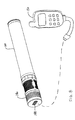
- Figure 8 illustrates a fuel cell device 100 with a modular head portion 140 that includes power conditioning circuitry and a connector 148 therein, and provides power to external devices through the connector 148.
- connector 148 is a USB (Universal Serial Bus) connector that provides a 5-volt output.
- USB Universal Serial Bus
- the modular head portion 140 can be used to connect the fuel cell device 100 with other components, and allow the fuel cell device 100 to charge a portable device such as, but not limited to, a cell phone 150, PDA, or any rechargeable device without need from grid power or a generator.
- a portable device such as, but not limited to, a cell phone 150, PDA, or any rechargeable device without need from grid power or a generator.
- Other types of modular heads can be provided such as heads that provide the utility of other devices such as, but not limited to, a laser pointer, a fan, a strobe light, a music player, or any other portable devices that use electrical power.
- the head portion 140 is powered by one or more fuel cells 160 of the fuel cell device 100.
- the one or more fuel cells 160 are each adapted to generate electricity. If a plurality of fuel cells is used, they can be connected in parallel, or in series, or in some combination of these. In an example, the one or more fuel cells are arranged radially underneath a grill 162. The number of fuel cells that can be used is from 1 to 50,000 fuel cells. In an example, twenty fuel cells are used to power a Luxeon LED emitter, available from LumiLED Lighting of San Jose, California. Many layers of micro-sized fuel cells can also be connected to make a fuel cell device.
- Examples of fuel cells include, but are not limited to, a hydrogen fuel cell, a direct methanol fuel cell, a reformed methanol fuel cell, a solid oxide fuel cell, an alkaline fuel cell, a polymer electrolyte membrane fuel cell, a proton exchange membrane fuel cell, or combinations of these.
- an electrochemical cell is formed on a substrate, such as a pleated substrate. For instance, a sheet of substrate material is corrugated. First and second troughs are defined on opposed faces of the substrate material. Ion-conducting regions are located in a common wall of the first and second troughs. In the ion-conducting regions ions can pass through the substrate material between the first and second troughs.
- an electrochemical cell has current-carrying structures underlying reaction layers.
- a core assembly includes an ion exchange membrane, an electrically conducting electrochemical reaction layer on at least a first side of the ion exchange membrane, and, an electrically-conductive current-carrying structure in electrical contact with the electrochemical reaction layer.
- An outer surface of the electrochemical reaction layer overlies at least a portion of the current-carrying structure.
- a thin layer cell structure comprising an ion exchange membrane having an electrochemical reaction layer on each side thereof.
- the ion exchange membrane can include a layer of unitary construction, or can include a composite layer made up of more than one material.
- An electrical current-carrying structure at least in part underlies one of the electrochemical reaction layers.
- a fuel cell in yet another example of a fuel cell, includes at least two unit reactors that are disposed adjacent to each other to form front and back sides of the compact fuel cell.
- the fuel cell further includes a front reactant plenum communicating with the front side and a back reactant plenum communicating with the back side. At least one of the reactant plenums includes a reactant.
- the unit reactors include a front cavity between front and back process layers, a back cavity between back and front process layers of adjacent unit reactors, where the process layers facilitate transport processes between reactant plenums.
- the unit reactors further include a front perimeter barrier disposed on the back process layer and substantially surrounding the back cavity, and a back perimeter barrier disposed on the front process layer substantially surrounding the front cavity.
- Each cavity communicates with a respective side of the fuel cell.
- At least one of the unit reactors include at least one frame formed from one of the process layers, at least one of the perimeter barriers, and at least one of the cavities.
- the one or more fuel cells include a fuel plenum 172 containing fuel, which is sourced from the fuel container 104.
- the fuel container 104 optionally contains hydrogen in a hydrogen storage medium such as metal hydride.
- a hydrogen storage medium such as metal hydride.
- Other fuels can be stored and other fuel storage media can be used, or not at all, if for example hydrogen gas is stored in compressed form.
- a metal hydride such as Lanthanum Nickel available from Alfa Aesar of Ward Hill, MA can be used to store hydrogen. Other metal hydrides are possible.
- the fuel container 104 is optionally used as the handle portion 102 ( Figure 1).
- fuels and fuel containing materials are also possible, such as but not limited to: methanol, formic acid, butane, chemical hydrides, borohydride compounds, hydrogen stored in a carbon-based storage material (i.e., carbon nanotubes, carbon nanofibres, activated carbon, etc.), compressed hydrogen, or liquid hydrogen.
- a carbon-based storage material i.e., carbon nanotubes, carbon nanofibres, activated carbon, etc.
- compressed hydrogen or liquid hydrogen.
- each fuel cell 160 includes an anode 166 in communication with or connected to the fuel plenum 172, and each fuel cell 150 further includes a cathode 174 in communication with an oxidant.
- oxygen in the ambient air is used as oxidant for the electrochemical reaction in the one or more fuel cells 160.
- One example of allowing communication of ambient air with the one or more fuel cells 160 is to provide a porous member over the fuel cells 160, such as a perforated grill 162 ( Figure 3).
- the grill 162 protects the fuel cells 160, and further allows for oxygen in ambient air to access the one or more fuel cells 160, where the oxygen acts as an oxidant for the one or more fuel cells 160.
- a cover 164 ( Figure 1), such as a plastic cover, is disposed over a seam, if any, of the porous member.
- an electrolyte 168 providing ion exchange capacity separates the anode and the cathode.
- electrolytes include an ion conducting membrane or a liquid electrolyte.
- electrolyte 168 includes a polymer exchange member, such as an ion conducting membrane, which is available under the name of NafionTM, from E.I. Dupont Company of Wilmington, Delaware.
- the fuel cells 160a, 160b, 160c, 160d are shown with a parallel connection between two sets of two fuel cells connected in series.
- One fuel cell 160a is connected in series to another fuel cell 160b.
- a third fuel cell 160c is connected in series to a fourth fuel cell 160d.
- Different numbers of fuel cells are possible and other parallel and serial combinations are possible to give different voltages and current outputs.
- all of the fuel cells are connected in parallel, and in another embodiment all of the fuel cells are connected in series.
- the fuel cells are connected in parallel and/or in series.
- a parallel-serial fuel cell stack is divided into sub-stacks.
- first sub-stack unit cells are oriented with their cathodes toward a first end plate.
- unit cells are oriented with their cathodes toward a second end plate.
- the first and second sub-stacks are arranged back-to-back.
- the electrical polarities of the unit cells in the first and second sub-stacks are oriented in opposite directions.
- a negative connection connects the anode of at least one of the fuel cells 160 to actuator 110.
- a positive connection connects at least one of the cathodes of the fuel cells to the actuator 110, and the actuator 110 optionally has an electrical disconnect.
- a positive connection and a negative connection connect a device to be powered, such as a light producing component or a light source, with the actuator 110.
- the components are arranged with the axis of the fuel cells 106 parallel to the main axis of a cylindrical fuel tank 104 and a rotary actuator 110.
- the actuator 110 is operatively coupled with a shut off feature that turns off power to the head portion 140.
- the actuator 110 can break the electrical connection to the head portion 140.
- the actuator 110 can cut off the fuel supply to the one or more fuel cells 160, for example, by turning off the pressure regulator 180.
- a shut off feature such as a valve operated by the actuator 110 that shuts off the flow of fuel from the fuel container 104 to the anode when the unit is not in use. Such a feature can help to extend the shelf life of the fuel cell device.
- the actuator 110 In addition to providing a shutoff between the fuel container 104 and the one or more fuel cells 160, the actuator 110 also optionally provides an electrical disconnect to break the electrical connection between the one or more fuel cells 160 and a load connected to the one or more fuel cells 160, for instance a feature to be powered, such as the LED 144.
- the actuator has two positions, such as ON and OFF.
- the actuator 110 has at least three distinct positions: ON, OFF, and STANDBY.
- the actuator 110 is physically moved, for example by rotation, to move the actuator between the various settings. In the ON position, both fuel is allowed to flow to the one or more fuel cells 160, and electricity is provided to the feature to be powered, such as the LED 144.
- the STANDBY setting is located between the ON and the OFF settings, and in the STANDBY setting, the fuel connection between the one or more fuel cells 160 and the fuel container 104 is open, but the electrical connection is broken.
- a visual indicator is provided with the fuel cell device 100, such as markings on the housing, or an indicator LED 112 ( Figure 1) providing the user with visual feedback when the actuator 110 is in the STANDBY position.
- the actuator 110 can be operatively coupled with the pressure regulator 180, as illustrated in Figures 4A and 4B.
- the pressure regulator 180 regulates the pressure of the fuel, for example, the hydrogen gas pressure from the hydride, down to a suitable pressure for the one or more fuel cells 160.
- the pressure regulator could regulate pressures up to 200 psi down to a pressure of approximately 0.5 to 15 psi.
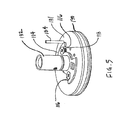
- Figures 4A, 4B, and 5 show a general view of a mechanism for connecting the actuator 110 to the pressure regulator 180 according to an embodiment of the fuel cell device 110, where Figure 4A shows the pressure regulator 180 (and actuator 110) in the closed position, and Figure 4B shows the pressure regulator 180 in the open position.
- the mechanism includes a disk 114 that has one or more grooves 116 therein.
- the disk 114 is coupled with the actuator 110 such that when the actuator 110 is moved, for instance by rotation, the disk 114 is rotated or otherwise moved.
- Flanged members 118 such as screws, are mechanically coupled to a pressure regulator diaphragm 181. The flanged members 118 allow for shutting the regulator valve off and adjustment to the shut off position.
- the flanged members 118 are received within the grooves 116, and are positioned relative to the disk 114 such that the disk 181 has a first longitudinal position when the flanged member 118 are engaged within the grooves 116, such as shown in Figure 4A, and the disk 181 has a second longitudinal position when the flanged member 118 is not engaged within the grooves 116, as shown in Figure 4B.
- the flanged members 118 can be set so the pressure regulator 180 is shut off when the actuator 110 is in the correct position.
- the pressure regulator 180 regulates the pressure of the fuel fed to the one or more fuel cells 160 through conduit 184.
- the disk 114 connected to the actuator 110 shuts off the pressure regulator by lifting the regulator diaphragm 182 up via the flanged members 118, and the pin 186 seals against an o-ring 188 to shut of flow of hydrogen gas from the fuel container 104 to the one or more fuel cells 160.
- the pressure regulator 180 is generally disposed between the one or more fuel cells 160 and the fuel container 104, in an option.
- a sealing member such as an O-ring 190, seals the pressure regulator 180 to the inside wall 105 of the fuel container 104.
- the one or more fuel cells 160 are mounted on a shaft 192 extending from the pressure regulator 180.
- the one or more fuel cells 160 operate through use of fuel that is contained within the fuel container 104. As the fuel in the one or more fuel cells is consumed, refueling must occur for continued use of the fuel cell device.
- a refueling assembly 200 is provided, as illustrated in Figure 6A, 6B, 7A, and 7B.
- An inlet port 202 is shown allowing fuel gas to flow through an inlet check valve 204 into the fuel container 104.
- the refueling assembly 200 is a pressure activated one-way valve that allows a flow of fluid, for example, fluid fuel, into the fuel container 104. The flow of fuel is allowed into the fuel container 104 during refueling, but does not allow fuel to flow back out of the fuel reservoir.
- a pressure relief valve 206 allows fuel gas to flow from the inside of the fuel container 104 to the outside environment should the pressure build up too high in the fuel container 104.
- the axis 208 of a resilient member, such as a spring 210, in the inlet check valve 204 is aligned approximately perpendicularly to the axis of the fuel container 104, which is oriented in and out of the page.
- the axis 212 of the pressure relief valve 206 is also aligned approximately perpendicularly to the axis of the fuel container 104, which is oriented in and out of the page.
- the fuel cell flashlight has a relatively long run time, and allows for higher brightness levels without substantially reducing run time.
- a further advantage is that the fuel cell flashlight provides a constant light output as long as fuel is supplied, providing a longer usable light run time, without requiring use of a DC-DC converter. This is particularly helpful for LED flashlights, which can otherwise be sensitive to voltage output levels.
- the fuel cell flashlight further provides for a more economical approach to powering the flashlight, as opposed to constantly replacing batteries.
- the fuel cell further provides the ability to handle many refueling cycles without impacting flashlight run time, delivering longer run times for many refueling cycles.
Landscapes
- Life Sciences & Earth Sciences (AREA)
- Engineering & Computer Science (AREA)
- Manufacturing & Machinery (AREA)
- Sustainable Development (AREA)
- Sustainable Energy (AREA)
- Chemical & Material Sciences (AREA)
- Chemical Kinetics & Catalysis (AREA)
- Electrochemistry (AREA)
- General Chemical & Material Sciences (AREA)
- Fuel Cell (AREA)
Applications Claiming Priority (1)
| Application Number | Priority Date | Filing Date | Title |
|---|---|---|---|
| US77295306P | 2006-02-14 | 2006-02-14 |
Publications (2)
| Publication Number | Publication Date |
|---|---|
| EP1821031A2 true EP1821031A2 (de) | 2007-08-22 |
| EP1821031A3 EP1821031A3 (de) | 2007-11-21 |
Family
ID=38048033
Family Applications (1)
| Application Number | Title | Priority Date | Filing Date |
|---|---|---|---|
| EP07102165A Ceased EP1821031A3 (de) | 2006-02-14 | 2007-02-12 | Brennstoffzellenvorrichtungen und Verfahren dafür |
Country Status (5)
| Country | Link |
|---|---|
| US (1) | US7964313B2 (de) |
| EP (1) | EP1821031A3 (de) |
| JP (1) | JP5066637B2 (de) |
| CN (1) | CN100544086C (de) |
| CA (1) | CA2577655C (de) |
Cited By (1)
| Publication number | Priority date | Publication date | Assignee | Title |
|---|---|---|---|---|
| EP2652827A4 (de) * | 2010-12-14 | 2016-08-10 | Intelligent Energy Ltd | Brennstoffzellensystem |
Families Citing this family (9)
| Publication number | Priority date | Publication date | Assignee | Title |
|---|---|---|---|---|
| EP2535830B1 (de) * | 2007-05-30 | 2018-11-21 | Ascensia Diabetes Care Holdings AG | Verfahren und System zur Verwaltung von Gesundheitsdaten |
| US8632354B2 (en) * | 2011-08-16 | 2014-01-21 | Micron Technology, Inc. | Interconnection systems |
| USD725588S1 (en) | 2012-06-13 | 2015-03-31 | Societe Bic | Mobile power source |
| CN102818129A (zh) * | 2012-08-30 | 2012-12-12 | 华荣科技股份有限公司 | 防爆工作灯及防爆工作套件 |
| US20140152231A1 (en) * | 2012-11-30 | 2014-06-05 | Pao-Feng Li | Dolly Charger |
| DE202013105876U1 (de) * | 2013-12-20 | 2015-03-24 | Wemas Absperrtechnik Gmbh | Baustellenleuchte |
| CN105174384B (zh) * | 2015-08-28 | 2019-02-01 | 陈志越 | 一体式富氢水的制造装置 |
| US12196380B2 (en) | 2022-05-24 | 2025-01-14 | Black & Decker Inc. | Portable illumination apparatus |
| US12385630B2 (en) | 2022-05-24 | 2025-08-12 | Black & Decker Inc. | Portable flashlight |
Family Cites Families (15)
| Publication number | Priority date | Publication date | Assignee | Title |
|---|---|---|---|---|
| JP4944300B2 (ja) | 2001-01-25 | 2012-05-30 | 本田技研工業株式会社 | 燃料電池システム |
| JP2003223243A (ja) * | 2002-01-29 | 2003-08-08 | Toshiba Corp | 情報機器 |
| JP4155021B2 (ja) * | 2002-02-28 | 2008-09-24 | カシオ計算機株式会社 | 発電型電源及び電子機器 |
| DE20205728U1 (de) | 2002-04-12 | 2002-07-25 | Zentrum für Sonnenenergie- und Wasserstoff-Forschung Baden Württemberg Gemeinnützige Stiftung, 89081 Ulm | Taschenlampe |
| US20040157111A1 (en) | 2002-11-28 | 2004-08-12 | Shigeru Sakamoto | Fuel cell |
| JP2004185936A (ja) * | 2002-12-02 | 2004-07-02 | Sanyo Electric Co Ltd | 燃料電池 |
| JP2004179074A (ja) * | 2002-11-28 | 2004-06-24 | Sanyo Electric Co Ltd | 燃料電池 |
| JP2004311041A (ja) * | 2003-04-02 | 2004-11-04 | Hitachi Lighting Ltd | 照明装置 |
| GB0315280D0 (en) | 2003-06-30 | 2003-08-06 | Voller Energy Ltd | Improvements relating to fuel cell systems |
| WO2005010427A1 (ja) * | 2003-07-25 | 2005-02-03 | Toyota Jidosha Kabushiki Kaisha | ガス供給装置 |
| KR20060086950A (ko) * | 2003-10-21 | 2006-08-01 | 알베르타 리써치 카운실 인코포레이티드 | 고체 산화물 연료 셀의 동작제어방법 및 장치 |
| US20060068239A1 (en) * | 2004-09-30 | 2006-03-30 | Yasuaki Norimatsu | Electric power source apparatus using fuel cell and method of controlling the same |
| JP4855743B2 (ja) * | 2004-09-30 | 2012-01-18 | 株式会社日立製作所 | 燃料電池を用いた電源装置およびその制御方法 |
| JP2006294470A (ja) | 2005-04-12 | 2006-10-26 | Toshiba Corp | 燃料電池ユニットおよび制御方法 |
| US8227144B2 (en) * | 2006-01-09 | 2012-07-24 | SOCIéTé BIC | Cellular reservoir and methods related thereto |
-
2007
- 2007-02-08 CA CA2577655A patent/CA2577655C/en not_active Expired - Fee Related
- 2007-02-09 US US11/673,416 patent/US7964313B2/en not_active Expired - Fee Related
- 2007-02-09 JP JP2007030522A patent/JP5066637B2/ja not_active Expired - Fee Related
- 2007-02-12 EP EP07102165A patent/EP1821031A3/de not_active Ceased
- 2007-02-14 CN CNB2007100801781A patent/CN100544086C/zh not_active Expired - Fee Related
Cited By (1)
| Publication number | Priority date | Publication date | Assignee | Title |
|---|---|---|---|---|
| EP2652827A4 (de) * | 2010-12-14 | 2016-08-10 | Intelligent Energy Ltd | Brennstoffzellensystem |
Also Published As
| Publication number | Publication date |
|---|---|
| CA2577655A1 (en) | 2007-08-14 |
| CN101022168A (zh) | 2007-08-22 |
| US20080003464A1 (en) | 2008-01-03 |
| JP2007242606A (ja) | 2007-09-20 |
| CN100544086C (zh) | 2009-09-23 |
| EP1821031A3 (de) | 2007-11-21 |
| CA2577655C (en) | 2011-04-05 |
| US7964313B2 (en) | 2011-06-21 |
| JP5066637B2 (ja) | 2012-11-07 |
Similar Documents
| Publication | Publication Date | Title |
|---|---|---|
| CA2577655C (en) | Fuel cell devices and method therefor | |
| EP2236423B1 (de) | Verfahren und Vorrichtung zum Befüllen eines Kraftstoffbehälters | |
| US6268077B1 (en) | Portable fuel cell power supply | |
| KR100977959B1 (ko) | 전기화학 디바이스 | |
| TWI257731B (en) | Cartridge with fuel supply and membrane electrode assembly stack | |
| US7859218B2 (en) | Power source system | |
| CN101138119A (zh) | 燃料电池系统及相关方法 | |
| US20090325009A1 (en) | Electric power supply apparatus and portable electronic device having the same | |
| KR20050077078A (ko) | 연료 전지 시스템 | |
| KR20050027040A (ko) | 연료 전지 시스템 | |
| US20110027682A1 (en) | Portable electronic device comprising fuel cell power system | |
| EP2652827B1 (de) | Brennstoffzellensystem | |
| JP5258203B2 (ja) | 燃料電池システム及び電子機器 | |
| KR100343392B1 (ko) | 알콜 연료전지를 이용한 휴대형 전원 공급장치 | |
| CN102017263A (zh) | 燃料盒和燃料电池系统 | |
| CN101366146A (zh) | 混合电源的方法和设备 | |
| JP2013020722A (ja) | 燃料電池発電システム | |
| JP2007335225A (ja) | 燃料電池システムおよび燃料電池システムの運転方法 | |
| JP2007335123A (ja) | 燃料電池システム、燃料電池システムを有する電気機器 | |
| US20080118792A1 (en) | Fuel cell system and driving method thereof | |
| JP2005346975A (ja) | 小型携帯電気機器用燃料電池および小型携帯電気機器 |
Legal Events
| Date | Code | Title | Description |
|---|---|---|---|
| PUAI | Public reference made under article 153(3) epc to a published international application that has entered the european phase |
Free format text: ORIGINAL CODE: 0009012 |
|
| AK | Designated contracting states |
Kind code of ref document: A2 Designated state(s): AT BE BG CH CY CZ DE DK EE ES FI FR GB GR HU IE IS IT LI LT LU LV MC NL PL PT RO SE SI SK TR |
|
| AX | Request for extension of the european patent |
Extension state: AL BA HR MK YU |
|
| PUAL | Search report despatched |
Free format text: ORIGINAL CODE: 0009013 |
|
| 17P | Request for examination filed |
Effective date: 20070907 |
|
| AK | Designated contracting states |
Kind code of ref document: A3 Designated state(s): AT BE BG CH CY CZ DE DK EE ES FI FR GB GR HU IE IS IT LI LT LU LV MC NL PL PT RO SE SI SK TR |
|
| AX | Request for extension of the european patent |
Extension state: AL BA HR MK YU |
|
| 17Q | First examination report despatched |
Effective date: 20080630 |
|
| AKX | Designation fees paid |
Designated state(s): AT BE BG CH CY CZ DE DK EE ES FI FR GB GR HU IE IS IT LI LT LU LV MC NL PL PT RO SE SI SK TR |
|
| RAP1 | Party data changed (applicant data changed or rights of an application transferred) |
Owner name: SOCIETE BIC |
|
| STAA | Information on the status of an ep patent application or granted ep patent |
Free format text: STATUS: THE APPLICATION HAS BEEN REFUSED |
|
| 18R | Application refused |
Effective date: 20121023 |