EP1651372B1 - Vorrichtung zur fertigung von kernpaketen - Google Patents
Vorrichtung zur fertigung von kernpaketen Download PDFInfo
- Publication number
- EP1651372B1 EP1651372B1 EP04722529A EP04722529A EP1651372B1 EP 1651372 B1 EP1651372 B1 EP 1651372B1 EP 04722529 A EP04722529 A EP 04722529A EP 04722529 A EP04722529 A EP 04722529A EP 1651372 B1 EP1651372 B1 EP 1651372B1
- Authority
- EP
- European Patent Office
- Prior art keywords
- station
- shooting
- tool
- tools
- gassing
- Prior art date
- Legal status (The legal status is an assumption and is not a legal conclusion. Google has not performed a legal analysis and makes no representation as to the accuracy of the status listed.)
- Expired - Lifetime
Links
- 239000004576 sand Substances 0.000 claims description 28
- 238000010926 purge Methods 0.000 claims description 10
- 238000005266 casting Methods 0.000 claims description 6
- 239000000969 carrier Substances 0.000 claims description 5
- 238000003032 molecular docking Methods 0.000 claims description 5
- 238000003825 pressing Methods 0.000 claims description 4
- 238000007664 blowing Methods 0.000 claims description 3
- 238000010304 firing Methods 0.000 description 16
- 238000004519 manufacturing process Methods 0.000 description 13
- 238000004140 cleaning Methods 0.000 description 8
- 230000008859 change Effects 0.000 description 4
- 238000005507 spraying Methods 0.000 description 4
- 238000004806 packaging method and process Methods 0.000 description 3
- 239000012190 activator Substances 0.000 description 2
- 239000003054 catalyst Substances 0.000 description 2
- 239000002184 metal Substances 0.000 description 2
- 238000000034 method Methods 0.000 description 2
- 239000003110 molding sand Substances 0.000 description 2
- 230000008901 benefit Effects 0.000 description 1
- 239000003795 chemical substances by application Substances 0.000 description 1
- 238000001816 cooling Methods 0.000 description 1
- 238000011161 development Methods 0.000 description 1
- 230000018109 developmental process Effects 0.000 description 1
- 238000005516 engineering process Methods 0.000 description 1
- 238000003958 fumigation Methods 0.000 description 1
- 239000011261 inert gas Substances 0.000 description 1
- 230000003993 interaction Effects 0.000 description 1
- 239000012778 molding material Substances 0.000 description 1
- 230000008569 process Effects 0.000 description 1
- 230000009467 reduction Effects 0.000 description 1
- 239000002904 solvent Substances 0.000 description 1
- 238000011144 upstream manufacturing Methods 0.000 description 1
- XLYOFNOQVPJJNP-UHFFFAOYSA-N water Substances O XLYOFNOQVPJJNP-UHFFFAOYSA-N 0.000 description 1
Images


Classifications
-
- B—PERFORMING OPERATIONS; TRANSPORTING
- B22—CASTING; POWDER METALLURGY
- B22C—FOUNDRY MOULDING
- B22C13/00—Moulding machines for making moulds or cores of particular shapes
- B22C13/12—Moulding machines for making moulds or cores of particular shapes for cores
-
- B—PERFORMING OPERATIONS; TRANSPORTING
- B22—CASTING; POWDER METALLURGY
- B22C—FOUNDRY MOULDING
- B22C9/00—Moulds or cores; Moulding processes
- B22C9/10—Cores; Manufacture or installation of cores
- B22C9/103—Multipart cores
-
- Y—GENERAL TAGGING OF NEW TECHNOLOGICAL DEVELOPMENTS; GENERAL TAGGING OF CROSS-SECTIONAL TECHNOLOGIES SPANNING OVER SEVERAL SECTIONS OF THE IPC; TECHNICAL SUBJECTS COVERED BY FORMER USPC CROSS-REFERENCE ART COLLECTIONS [XRACs] AND DIGESTS
- Y10—TECHNICAL SUBJECTS COVERED BY FORMER USPC
- Y10T—TECHNICAL SUBJECTS COVERED BY FORMER US CLASSIFICATION
- Y10T29/00—Metal working
- Y10T29/49—Method of mechanical manufacture
- Y10T29/4998—Combined manufacture including applying or shaping of fluent material
- Y10T29/49982—Coating
- Y10T29/49984—Coating and casting
-
- Y—GENERAL TAGGING OF NEW TECHNOLOGICAL DEVELOPMENTS; GENERAL TAGGING OF CROSS-SECTIONAL TECHNOLOGIES SPANNING OVER SEVERAL SECTIONS OF THE IPC; TECHNICAL SUBJECTS COVERED BY FORMER USPC CROSS-REFERENCE ART COLLECTIONS [XRACs] AND DIGESTS
- Y10—TECHNICAL SUBJECTS COVERED BY FORMER USPC
- Y10T—TECHNICAL SUBJECTS COVERED BY FORMER US CLASSIFICATION
- Y10T29/00—Metal working
- Y10T29/53—Means to assemble or disassemble
- Y10T29/53039—Means to assemble or disassemble with control means energized in response to activator stimulated by condition sensor
- Y10T29/53048—Multiple station assembly or disassembly apparatus
-
- Y—GENERAL TAGGING OF NEW TECHNOLOGICAL DEVELOPMENTS; GENERAL TAGGING OF CROSS-SECTIONAL TECHNOLOGIES SPANNING OVER SEVERAL SECTIONS OF THE IPC; TECHNICAL SUBJECTS COVERED BY FORMER USPC CROSS-REFERENCE ART COLLECTIONS [XRACs] AND DIGESTS
- Y10—TECHNICAL SUBJECTS COVERED BY FORMER USPC
- Y10T—TECHNICAL SUBJECTS COVERED BY FORMER US CLASSIFICATION
- Y10T29/00—Metal working
- Y10T29/53—Means to assemble or disassemble
- Y10T29/53313—Means to interrelatedly feed plural work parts from plural sources without manual intervention
Definitions
- the invention relates to a device for the production of core packages serving in particular for casting engine blocks and cylinder heads, with a shooting station in which individual cores are shot and a removal station in which the shot cores are taken and transferred to an assembly line for packaging, wherein in the Shooting station a preferably two-part tool a sand magazine and a shooting plate comprehensive shot hood together with a shooting head can be assigned.
- the invention relates generally to the manufacture of cores, which are completed to form a core package.
- the core package serves as a mold in foundry technology.
- foundry cores or molds are usually made of separate parts for casting of fittings of any kind, merged and connected together to form a mold or to a core package or mold package.
- These core packages are then filled to produce a metallic workpiece, for example, with molten metal, wherein in series production to be filled with molten metal core packages in a row lined up the production line.
- a double tool is rotatable about a horizontal axis, while a firing cap together with the firing head can be pivoted about a vertical axis and can be coupled to the tool.
- the removal station corresponds to the shooting station in which the vertically divided tool is opened there and the shot core is removed for further processing.
- the from the DE 31 48 461 C1 known core and mask shooting machine is at best suitable for shooting two different cores and is therefore for the production a complete, multi-core core package is not suitable for casting engine blocks and cylinder heads.
- the known core and mask shooting machine is at most suitable for the production of one and the same core, wherein the duplicity of the tool can serve to replace it, without the production process has to be stopped, namely by the worn or contaminated tool against the other by the horizontal pivoting movement is exchanged.
- An automatic production of complete core packages is certainly not possible with the known core and mask shooting machine.
- the present invention is based on the object, a generic device for the production of particular for casting engine blocks and cylinder heads serving core packages such and further, that an automatic production of complete core packages with the smallest possible space requirement is possible.
- a generic device is characterized in that a plurality of tools for shooting different cores are arranged on a turntable that by turning the turntable, the tools are successively in the shooting station and from the shooting station together with the shot cores in the removal station can be brought.
- the turntable is equipped with tools according to the number of required cores, so that they are - supplied via the turntable - in the order of need of the shooting station. Accordingly, the shot cores are fed together with the tool in the predetermined order of the removal station, so that the cores are taken there in turn - again according to demand. An automatic packaging of cores to a core package is thus possible.
- the size of the turntable can be specified according to the requirements. Accordingly, different numbers of tools can be arranged on the turntable preferably equidistant to each other.
- the turntable is equipped in the sense of a carousel with the tools supporting arms, wherein the arms extend in a star-shaped outward.
- the arrangement of six tools on the turntable in question here is a six-station turnstile with six different or at least partially identical tools.
- the tools are arranged together with tool carriers and the tool carrier holding racks on the turntable.
- special lifting devices are provided, which are preferably associated with the tool carrier.
- the tool carrier and / or the lifting device may be assigned a lower ejection device for ejecting the core, wherein such an arrangement is not mandatory.
- the lifting devices associated with the tools on the turntable operate hydraulically or pneumatically. In any case, these are lifting devices that can be moved together with the tools, namely because of the fixed assignment of the lifting device to the respective tool.
- the respective core is fired with the respective tool located there.
- the shooting head required for firing is stationary in the shooting station.
- the tool comes with the individual Pressed shot plate and the sand magazine against the shooting head, so that the shooting process can take place under the influence of compressed air.
- the sand bunker and the shot hoods or the attached shot plates can be used in water cooled version.
- thedewasserzu- or -ablauf are preferably automatically automatically docked on the turntable and in the shooting station.
- the temperature-sensitive molding sand can be kept in a good shootable state, namely by the thus realized cooling.
- the sand magazines should be equipped with a lid.
- the lid is removed during filling and in the shooting station and then placed back on the magazine. This ensures that the solvents in the sand can not escape so quickly and the sand does not dry out. In addition, an undesired prereaction of the molding sand is avoided. Possibly.
- the cavity in the sand hopper could be filled with an inert gas to avoid a reaction in any case.
- the tools are arranged together with a lifting device for raising and pressing the tool against the shooting head on the turntable.
- the lifting device used to open the tool can also be used to bring the tool into the firing position.
- special lifting device which is arranged under the turntable or under the boom and thus under the tool stationary in the shooting station. Accordingly, the tool is placed on the turntable in the shooting position, so that from below the tool, the stationary lifting device can act.
- the weft plate together with a sand magazine adapted to the respective tool, this is provided. So it is of further advantage if the tool before or in the shooting station a filled with core sand, suitable for each tool firing cap, comprising the adapted weft plate with the sand magazine, is assigned for docking and subsequent shooting. Preferably, this assignment takes place in the shooting station, so that the shooting can take place immediately after the docking of the shooting head.
- the respective firing hood could be fed linearly to the shooting station.
- the firing hood is fed via a further turntable to the respective tool in the shooting station.
- the turntable carrying the tools and the turntable carrying the firing cap rotate in the same direction, so that with appropriate arrangement of the two turntables, the conveying directions of the tools and shotguns in the shooting station are directed counter to each other.
- the turntable carrying the shot hoods is designed in the sense of a carousel with the jib-carrying arms. According to the number of tools, for example, six different tools, a corresponding number of shot caps is provided, as well as six shot hoods with weft plate and sand magazine.
- the boom carrying the shotgun arms extend in a star shape outwards, the turntable is equipped according to the number of different tools with a corresponding number of different shot hoods.
- the shotguns are sequentially brought into a filling station and from the filling station to the shooting station.
- a preferably stationary sand bunker is provided, via which the sand magazines of the shot hoods are filled with a presettable amount of core sand.
- the stationary sand bunker therefore serves as a sand reservoir from which the sand magazines / shot hoods can be individually filled.
- a Schusshauben circuitstation is provided for the purpose of further automation of the device in question here.
- the shotguns to be loaded can be removed from the firing hood transfer device, in accordance with the position of the turntable carrying the shot hoods.
- the shotguns can be replaced one after the other or individually.
- the firing hood transfer device advantageously comprises two conveyor sections, which together form a linear conveyor. At least one manipulator is associated with the linear conveyor, which generates the transfer of the shot caps from the firing hood transfer device to the turntable or from the turntable to the firing hood transfer device.
- this turntable is assigned to the shooting station. Between the shooting station and the removal station, at least one further treatment station is provided in the immediate vicinity of the turntable carrying the tools. As a further treatment station, one or more gassing stations could be provided. These gassing stations are used for further treatment of the already shot and still in the closed tool core.
- Each tool can have a combined gassing plate with integrated upper ejector plate. Due to the shotgun image of the weft plate or due to the shape of the cores, each tool requires an individual combined gassing and ejection plate.
- a device is rotated on the turntable with each tool carrier, on which a combined gassing and ejection plate is inserted. After the shooting station, in each case the combined gassing and ejection plate is pressed onto the tool upper part via the tool method and through the stationary abutments when the tool carrier is driven into the gassing or rinsing station.
- a gassing with gassing hood is provided in the gassing, against which the closed tool with the closed core can be pressed.
- a stationary lifting device could be provided, which is associated with the stationary fumigation station.
- the tool can be Press by means of this lifting device against the gassing hood, so that the gassing can take place.
- the gassing station can be assigned a suction device with a corresponding suction connection.
- the gassing device could further comprise very special ejection means for ejecting the core, preferably from the upper mold half.
- the ejection means could in turn comprise an ejection plate, so that a gentle ejection of the workpiece is possible with the tool open.
- one or more rinsing stations could be provided corresponding to the gassing stations. Combined gassing / rinsing stations are also conceivable.
- the rinsing station could in turn comprise a suction device with a suction connection in accordance with the provisions in the gassing stations.
- a tool change station is preferably provided between the shooting station and the removal station.
- Such a tool change station could be combined with a gassing / rinsing station.
- the tools similar to the shotgun caps or the Schusshaubendron, the tool-carrying and this rotating turntable via a further turntable or be discharged from there.
- the tools to be replaced can be transferred to a tool transfer device in the tool change station and the tools to be loaded can be removed from the tool transfer device.
- the tool transfer device may be a linear conveyor which, as in the case of shot caps, comprises two conveyor lines and at least one manipulator.
- the exchanged tools can be fed to a separate cleaning device or a magazine or warehouse.
- a further treatment station could be provided, namely one or more cleaning stations for cleaning the tool.
- the cleaning station could comprise a blow-out device for blowing out the opened tool as well as a spraying device for spraying the inner surfaces of the tool with release agent.
- processing stations discussed above can be arranged several times according to requirements.
- the number of tools and shot caps is given according to the needs of individual cores in relation to the core package to be packaged.
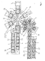
- Fig. 1 shows a device for the production of core packages, which in turn serve for the casting of engine blocks and cylinder heads.
- the device comprises a shooting station 1 in which individual cores are fired. Furthermore, the device comprises a removal station 2, in which the shot cores are removed and transferred for packaging to a subsequent assembly line 3 there.
- a shot cap 7 comprising a sand magazine 5 and a shooting plate 6 together with a shooting head 8 is assigned to a two-part tool 4 here.
- a turntable 9 which carries a plurality of tools 4 for shooting different cores. By turning the turntable 9, the tools 4 are successively moved into the shooting station 1 and from the shooting station 1 together with the shot cores in the removal station 2.
- Fig. 1 can be seen from the distance that the turntable 9 carries a total of six tools 4, which are arranged equidistant from each other. Finally, the turntable 9 is equipped in the sense of a carousel with the tools 4 supporting arms 10, wherein the arms 10 extend in a star shape to the outside.
- Fig. 2 shows the shooting station 1 and can be seen that the tools 4 are arranged together with tool carriers 11 and the tool holder 11 holding racks 12 on the turntable 9.
- 4 lifting devices 13 are provided for opening the tool, which are assigned directly to the tool 4 and the tool carrier 11.
- FIG. 2 further shows that the shooting head 8 is stationarily arranged in the shooting station 1, wherein the tool 4 with the shooting plate 6 and the sand magazine 5 can be pressed against the shooting head 8.
- the sand magazine 5 and the weft plate 6 together form the firing hood 7.
- FIG. 2 also shows that a further lifting device 14 under the turntable 9 or under its arms 10th and thus also under the tool 4 stationary in the shooting station 1 is arranged. Both lifting devices 13, 14 can work hydraulically or pneumatically.
- FIG. 1 and 2 show together that the tool 4 in the shooting station 1 is filled with a core sand, associated with the respective tool 4 firing hood 7 is assigned for docking and subsequent shooting.
- the firing cap 7 - together with the sand hopper 5 and the weft plate 6 - is fed via a further turntable 15 to the tool 4.
- the assignment of the two turntables 9, 15 is such that the turntable 9 carrying the tools 4 and the turntable 15 carrying the shot hoods rotate in the same direction, so that the conveying direction of the tools 4 and shooting hoods 7 in the shooting station 1 are opposite to each other.
- the turntable 7 carrying rotary table 15 is designed in the sense of a carousel with the shot hoods supporting arms 16, wherein the boom 16 extend in a star-shaped outward.
- the turntable 15 is equipped according to the number of different tools 4 with a corresponding number of shot hoods 7.
- the shot hoods 7 are successively moved into a filling station 17, which is the shooting station 1 upstream. From the filling station 17, the shot hoods 7 are rotated into the shooting station 1.
- the filling station 17, which is merely indicated in FIG. 1, comprises a stationary sand bunker, which can not be seen in FIG. FIG. 1 further reveals that between the shooting station 1 and the filling station 17 - based on the arrangement of the rotary table 7 carrying the shot hoods 7 - a shot changing station 18 is provided.
- a shot changing station 18 is provided between the shooting station 1 and the filling station 17 - based on the arrangement of the rotary table 7 carrying the shot hoods 7 - a shot changing station 18 is provided.
- the Schusshauben functionalstation 18 to be exchanged shot caps 7 are transferred to a Schusshaubentransfer annoying 19 and it be removed from the Schusshaubentransfer annoying 19 to be loaded shot caps 7, from there to the filling station 17 and finally to the shooting station 1 for docking with the tool. 4
- the firing hood transfer device 19 comprises a linear conveyor 20 with two conveyor lines 21, 22 and a manipulator not shown in the figure.
- the conveyor line 22 is used to supply new shot hoods 7 and the conveyor line 21 serves for the removal of exchanged or to be cleaned shot hoods 7th
- FIG. 1 further shows that a further treatment station is provided between the shooting station 1 and the removal station 2, namely a gassing station 23.
- a gassing station 23 is shown in detail in FIG. 3 as part of a schematic side view.
- the gassing station may comprise a treatment device, namely for the gassing and / or purge air treated with an activator, catalyst or the like.
- gassing stations 23, 29 and two rinsing stations 23, 28 are provided.
- the tool changing station 29 also serves as a gassing station at the same time. This will be described later.
- the gassing station 23 comprises a stationary abutment 31 and per tool carrier a movable device 32 with docked combined gassing and ejection plate 25.
- the ejector is marked with reference numeral 33.
- the ejection cylinder 34 and the rail 35 is shown.
- tool-specific combined gassing and ejection plates 32 are docked. These are moved after the shooting station on the tool and pressed by lifting the complete tool carrier, by the lifting device 26, against the abutment 31 and the tool shell.
- the abutment 31 is provided with one or more ports through which the gassing or purging air is introduced into the combined gassing and ejection plate 32.
- the gassing device 24 or the tool changing station 29 comprising the gassing station furthermore comprises an ejection means 27, specifically a tool-specific ejection plate 32 or an ejector 33 for ejecting the cores from the upper die 4 or for cleaning the bullet holes.
- This ejection plate is an integral part of the combined upper gassing and ejection plate 31.
- the ejection means are activated as needed to level the shot positions after the shot and before the gassing and in the core unloading station 2 for ejecting the cores.
- the gassing station can also be used with the use of appropriate molding materials as a rinsing station. This includes a treatment unit for the gassing / purge air treated with an activator, catalyst.
- the rinsing station 28 also comprises a suction device with a corresponding suction connection, although this is not shown in the figures.
- one of the gassing stations 23 can be designed as a combined gassing station and tool changing station.
- a tool change station 29 is provided, which is activated only when needed. Otherwise, the tool changing station 29 operates as a gassing station 23.
- FIG. 1 reveals, in relation to the tool changing station 29, that the tools 4 to be exchanged are transferred there to a tool transfer device 30 and the tools 4 to be loaded are removed from the tool transfer device 30.
- the tool transfer device 30 has a linear conveyor 31 with two conveyor sections 32, 33. There provided manipulator is not shown in Fig. 1.
- FIG. 1 shows a further treatment station, namely between the removal station 2 and the shooting station 1.
- a cleaning station 34 is provided for cleaning the opened tool.
- This cleaning station 34 comprises a blow-out device for blowing out the opened tool and a spraying device for spraying the inner surfaces of the tool, so that a suitable separating means for facilitating the ejection or removal of the core can be provided.
Landscapes
- Engineering & Computer Science (AREA)
- Mechanical Engineering (AREA)
- Casting Devices For Molds (AREA)
- Cleaning By Liquid Or Steam (AREA)
- Casting Support Devices, Ladles, And Melt Control Thereby (AREA)
Applications Claiming Priority (2)
| Application Number | Priority Date | Filing Date | Title |
|---|---|---|---|
| DE10336395 | 2003-08-06 | ||
| PCT/DE2004/000599 WO2005014204A1 (de) | 2003-08-06 | 2004-03-23 | Vorrichtung zur fertigung von kernpaketen |
Publications (2)
| Publication Number | Publication Date |
|---|---|
| EP1651372A1 EP1651372A1 (de) | 2006-05-03 |
| EP1651372B1 true EP1651372B1 (de) | 2007-12-26 |
Family
ID=34129512
Family Applications (1)
| Application Number | Title | Priority Date | Filing Date |
|---|---|---|---|
| EP04722529A Expired - Lifetime EP1651372B1 (de) | 2003-08-06 | 2004-03-23 | Vorrichtung zur fertigung von kernpaketen |
Country Status (7)
| Country | Link |
|---|---|
| US (1) | US20070039169A1 (ja) |
| EP (1) | EP1651372B1 (ja) |
| JP (1) | JP2007501126A (ja) |
| CA (1) | CA2534782A1 (ja) |
| DE (2) | DE102004014542B4 (ja) |
| ES (1) | ES2298736T3 (ja) |
| WO (1) | WO2005014204A1 (ja) |
Cited By (1)
| Publication number | Priority date | Publication date | Assignee | Title |
|---|---|---|---|---|
| CN105964948A (zh) * | 2016-06-27 | 2016-09-28 | 霍山县忠福机电科技有限公司 | 一种高效造芯机 |
Families Citing this family (14)
| Publication number | Priority date | Publication date | Assignee | Title |
|---|---|---|---|---|
| CN102785068B (zh) * | 2012-07-27 | 2014-08-20 | 厦门精合电气自动化有限公司 | 一种机械手与转盘联动装置 |
| CN103056656B (zh) * | 2013-02-01 | 2015-03-11 | 周俊雄 | 一种电位器组装设备 |
| CN103192036B (zh) * | 2013-04-24 | 2016-01-06 | 无锡市蠡湖铸业有限公司 | 全自动圆盘射芯机 |
| CN105014871A (zh) * | 2015-08-17 | 2015-11-04 | 广州达意隆包装机械股份有限公司 | 一种公仔注塑设备及其自动上下料注塑方法 |
| CN105196048B (zh) * | 2015-09-30 | 2017-07-28 | 江苏比微曼智能科技有限公司 | 散热片零部件组装机 |
| ES2839284T3 (es) | 2016-07-19 | 2021-07-05 | Loramendi S Coop | Máquina de fabricación de machos de arena |
| CN106493557A (zh) * | 2016-09-20 | 2017-03-15 | 瑞安市富日包装机械有限公司 | 维生素瓶盖组合机 |
| CN106311989B (zh) * | 2016-10-31 | 2018-03-20 | 常州先进制造技术研究所 | 一种用于浇冒口生产的自动化射芯分模系统 |
| CN107350432B (zh) * | 2017-07-14 | 2019-04-05 | 常州工学院 | 一种射芯机的自动取芯转运装置 |
| CN107553130B (zh) * | 2017-09-20 | 2019-04-05 | 重庆工商大学 | 一种能够进行插芯组装的光纤头全自动组装机 |
| CN108160768B (zh) * | 2017-12-18 | 2019-12-27 | 无锡众望四维科技有限公司 | 一种盘头打弯设备 |
| CN108188736B (zh) * | 2018-03-23 | 2023-08-15 | 浙江亿宝科技有限公司 | 一种换向器自动装配机 |
| CN108941471B (zh) * | 2018-07-27 | 2020-05-01 | 河北丰德机械制造有限公司 | 一种覆膜砂多工位全自动制壳机 |
| CN109121065A (zh) * | 2018-09-21 | 2019-01-01 | 深圳市俊杰诚科技有限公司 | 一种tv喇叭组装生产线的工艺方法 |
Family Cites Families (4)
| Publication number | Priority date | Publication date | Assignee | Title |
|---|---|---|---|---|
| US4184533A (en) * | 1978-05-30 | 1980-01-22 | Esco Corporation | Machine for shaping sand into cores or molds |
| DE3148461C1 (de) * | 1981-12-08 | 1983-04-14 | Adolf Hottinger, Gießerei und Maschinenbau GmbH, 6800 Mannheim | Kern- und Maskenschießmaschine |
| DE4006176A1 (de) * | 1990-02-28 | 1991-09-05 | Hottinger Adolf Masch | Verfahren und vorrichtung zum herstellen von kernen fuer giessereizwecke |
| DE4226778A1 (de) * | 1992-08-13 | 1994-02-17 | Badische Maschf Gmbh | Verfahren zum Transportieren von Formkasten und nach dem Verfahren arbeitende Gießerei-Formanlage |
-
2004
- 2004-03-23 EP EP04722529A patent/EP1651372B1/de not_active Expired - Lifetime
- 2004-03-23 DE DE102004014542A patent/DE102004014542B4/de not_active Expired - Fee Related
- 2004-03-23 CA CA002534782A patent/CA2534782A1/en not_active Abandoned
- 2004-03-23 ES ES04722529T patent/ES2298736T3/es not_active Expired - Lifetime
- 2004-03-23 JP JP2006522204A patent/JP2007501126A/ja active Pending
- 2004-03-23 DE DE502004005785T patent/DE502004005785D1/de not_active Expired - Fee Related
- 2004-03-23 WO PCT/DE2004/000599 patent/WO2005014204A1/de active IP Right Grant
-
2006
- 2006-02-06 US US11/347,952 patent/US20070039169A1/en not_active Abandoned
Cited By (1)
| Publication number | Priority date | Publication date | Assignee | Title |
|---|---|---|---|---|
| CN105964948A (zh) * | 2016-06-27 | 2016-09-28 | 霍山县忠福机电科技有限公司 | 一种高效造芯机 |
Also Published As
| Publication number | Publication date |
|---|---|
| WO2005014204A1 (de) | 2005-02-17 |
| DE102004014542A1 (de) | 2005-03-17 |
| US20070039169A1 (en) | 2007-02-22 |
| CA2534782A1 (en) | 2005-02-17 |
| ES2298736T3 (es) | 2008-05-16 |
| DE102004014542B4 (de) | 2007-10-31 |
| DE502004005785D1 (de) | 2008-02-07 |
| JP2007501126A (ja) | 2007-01-25 |
| EP1651372A1 (de) | 2006-05-03 |
Similar Documents
| Publication | Publication Date | Title |
|---|---|---|
| EP1651372B1 (de) | Vorrichtung zur fertigung von kernpaketen | |
| DE102008004773B4 (de) | Verfahren zum Umrüsten einer Blasmaschine | |
| DE2814715C3 (de) | Rotierende, kontinuierlich arbeitende Formvorrichtung für Gießkerne | |
| EP1731453B1 (de) | Verfahren und Vorrichtung zum Stapeln von tiefgezogenen Artikeln | |
| DE3523110A1 (de) | Verfahren zum automatisierten herstellen eines formkoerpers aus kunststoff und vorrichtung zur durchfuehrung dieses verfahrens | |
| DE3316951C2 (ja) | ||
| EP0444431B1 (de) | Verfahren und Vorrichtung zum Herstellen von Kernen für Giessereizwecke | |
| EP0397674A1 (de) | Verfahren und anlage zur herstellung von formteilen aus kunststoff. | |
| DE3816181C2 (ja) | ||
| AT122171B (de) | Fördereinrichtung für Glasgefäße. | |
| EP0636438B1 (de) | Vorrichtung und Verfahren zur Schusshaubenreinigung bei der Herstellung giessfertiger Masken bzw. Kernpakete | |
| DE4103538C1 (en) | Handling and cleaning industrial transport crates - uses machine with turntable rotating crate about vertical axis | |
| DE1908316A1 (de) | Druckgiessmaschine | |
| DE3123651A1 (de) | Verfahren und maschine fuer das abtrennen des giesssystems von gussstuecken | |
| DE10007333C2 (de) | Vorrichtung zum Stapeln von Behältern aus thermoplastischem Kunststoff | |
| DE3337243A1 (de) | Einrichtung zur fertigung gepresster gegenstaende | |
| EP0732977B1 (de) | Vorrichtung zum schiessen von giessereikernen oder -formen | |
| EP1651371A2 (de) | Vorrichtung zur fertigung von kernpaketen | |
| DE924499C (de) | Ununterbrochen umlaufende endlose Foerdervorrichtung mit Werkstuecktraegern | |
| DE10004611A1 (de) | Backeinrichtung zur Herstellung insbesondere hochwandiger Formkörper aus einer backbaren Formmasse | |
| EP2776209B1 (de) | Verfahren zum taktweisen abschirmen einer arbeitskammeröffnung sowie eine abschirmvorrichtung zur durchführung des verfahrens | |
| EP0462990B1 (de) | Transportvorrichtung für giessereikerne und -formen | |
| DE1241047B (de) | Verfahren und Maschine zum Herstellen von Giessformen | |
| DE1456625A1 (de) | Vorrichtung zur Fertigbearbeitung von Werkstuecken | |
| AT501716B1 (de) | Verfahren zum betrieb einer spritzgiessmaschine |
Legal Events
| Date | Code | Title | Description |
|---|---|---|---|
| PUAI | Public reference made under article 153(3) epc to a published international application that has entered the european phase |
Free format text: ORIGINAL CODE: 0009012 |
|
| 17P | Request for examination filed |
Effective date: 20060121 |
|
| AK | Designated contracting states |
Kind code of ref document: A1 Designated state(s): CH DE ES FR GB IT LI |
|
| DAX | Request for extension of the european patent (deleted) | ||
| RBV | Designated contracting states (corrected) |
Designated state(s): CH DE ES FR GB IT LI |
|
| GRAP | Despatch of communication of intention to grant a patent |
Free format text: ORIGINAL CODE: EPIDOSNIGR1 |
|
| GRAS | Grant fee paid |
Free format text: ORIGINAL CODE: EPIDOSNIGR3 |
|
| GRAA | (expected) grant |
Free format text: ORIGINAL CODE: 0009210 |
|
| RAP1 | Party data changed (applicant data changed or rights of an application transferred) |
Owner name: HOTTINGER MASCHINENBAU GMBH |
|
| AK | Designated contracting states |
Kind code of ref document: B1 Designated state(s): CH DE ES FR GB IT LI |
|
| REG | Reference to a national code |
Ref country code: GB Ref legal event code: FG4D Free format text: NOT ENGLISH |
|
| REG | Reference to a national code |
Ref country code: CH Ref legal event code: EP |
|
| REF | Corresponds to: |
Ref document number: 502004005785 Country of ref document: DE Date of ref document: 20080207 Kind code of ref document: P |
|
| GBT | Gb: translation of ep patent filed (gb section 77(6)(a)/1977) |
Effective date: 20080123 |
|
| PGFP | Annual fee paid to national office [announced via postgrant information from national office to epo] |
Ref country code: ES Payment date: 20080328 Year of fee payment: 5 Ref country code: CH Payment date: 20080328 Year of fee payment: 5 |
|
| REG | Reference to a national code |
Ref country code: ES Ref legal event code: FG2A Ref document number: 2298736 Country of ref document: ES Kind code of ref document: T3 |
|
| PGFP | Annual fee paid to national office [announced via postgrant information from national office to epo] |
Ref country code: IT Payment date: 20080319 Year of fee payment: 5 Ref country code: GB Payment date: 20080326 Year of fee payment: 5 |
|
| ET | Fr: translation filed | ||
| PGFP | Annual fee paid to national office [announced via postgrant information from national office to epo] |
Ref country code: DE Payment date: 20080314 Year of fee payment: 5 |
|
| PLBE | No opposition filed within time limit |
Free format text: ORIGINAL CODE: 0009261 |
|
| STAA | Information on the status of an ep patent application or granted ep patent |
Free format text: STATUS: NO OPPOSITION FILED WITHIN TIME LIMIT |
|
| PGFP | Annual fee paid to national office [announced via postgrant information from national office to epo] |
Ref country code: FR Payment date: 20080319 Year of fee payment: 5 |
|
| 26N | No opposition filed |
Effective date: 20080929 |
|
| REG | Reference to a national code |
Ref country code: CH Ref legal event code: PL |
|
| GBPC | Gb: european patent ceased through non-payment of renewal fee |
Effective date: 20090323 |
|
| REG | Reference to a national code |
Ref country code: FR Ref legal event code: ST Effective date: 20091130 |
|
| PG25 | Lapsed in a contracting state [announced via postgrant information from national office to epo] |
Ref country code: LI Free format text: LAPSE BECAUSE OF NON-PAYMENT OF DUE FEES Effective date: 20090331 Ref country code: DE Free format text: LAPSE BECAUSE OF NON-PAYMENT OF DUE FEES Effective date: 20091001 Ref country code: CH Free format text: LAPSE BECAUSE OF NON-PAYMENT OF DUE FEES Effective date: 20090331 |
|
| PG25 | Lapsed in a contracting state [announced via postgrant information from national office to epo] |
Ref country code: GB Free format text: LAPSE BECAUSE OF NON-PAYMENT OF DUE FEES Effective date: 20090323 Ref country code: FR Free format text: LAPSE BECAUSE OF NON-PAYMENT OF DUE FEES Effective date: 20091123 |
|
| REG | Reference to a national code |
Ref country code: ES Ref legal event code: FD2A Effective date: 20090324 |
|
| PG25 | Lapsed in a contracting state [announced via postgrant information from national office to epo] |
Ref country code: ES Free format text: LAPSE BECAUSE OF NON-PAYMENT OF DUE FEES Effective date: 20090324 |
|
| PG25 | Lapsed in a contracting state [announced via postgrant information from national office to epo] |
Ref country code: IT Free format text: LAPSE BECAUSE OF NON-PAYMENT OF DUE FEES Effective date: 20090323 |