EP1632726B1 - Ceiling suspended type air conditioner - Google Patents
Ceiling suspended type air conditioner Download PDFInfo
- Publication number
- EP1632726B1 EP1632726B1 EP05017877.1A EP05017877A EP1632726B1 EP 1632726 B1 EP1632726 B1 EP 1632726B1 EP 05017877 A EP05017877 A EP 05017877A EP 1632726 B1 EP1632726 B1 EP 1632726B1
- Authority
- EP
- European Patent Office
- Prior art keywords
- air
- air supply
- total enthalpy
- main body
- duct connection
- Prior art date
- Legal status (The legal status is an assumption and is not a legal conclusion. Google has not performed a legal analysis and makes no representation as to the accuracy of the status listed.)
- Expired - Lifetime
Links
Images

Classifications
-
- F—MECHANICAL ENGINEERING; LIGHTING; HEATING; WEAPONS; BLASTING
- F24—HEATING; RANGES; VENTILATING
- F24F—AIR-CONDITIONING; AIR-HUMIDIFICATION; VENTILATION; USE OF AIR CURRENTS FOR SCREENING
- F24F13/00—Details common to, or for air-conditioning, air-humidification, ventilation or use of air currents for screening
- F24F13/32—Supports for air-conditioning, air-humidification or ventilation units
-
- F—MECHANICAL ENGINEERING; LIGHTING; HEATING; WEAPONS; BLASTING
- F24—HEATING; RANGES; VENTILATING
- F24F—AIR-CONDITIONING; AIR-HUMIDIFICATION; VENTILATION; USE OF AIR CURRENTS FOR SCREENING
- F24F7/00—Ventilation
- F24F7/04—Ventilation with ducting systems, e.g. by double walls; with natural circulation
- F24F7/06—Ventilation with ducting systems, e.g. by double walls; with natural circulation with forced air circulation, e.g. by fan positioning of a ventilator in or against a conduit
- F24F7/08—Ventilation with ducting systems, e.g. by double walls; with natural circulation with forced air circulation, e.g. by fan positioning of a ventilator in or against a conduit with separate ducts for supplied and exhausted air with provisions for reversal of the input and output systems
-
- F—MECHANICAL ENGINEERING; LIGHTING; HEATING; WEAPONS; BLASTING
- F24—HEATING; RANGES; VENTILATING
- F24F—AIR-CONDITIONING; AIR-HUMIDIFICATION; VENTILATION; USE OF AIR CURRENTS FOR SCREENING
- F24F1/00—Room units for air-conditioning, e.g. separate or self-contained units or units receiving primary air from a central station
- F24F1/02—Self-contained room units for air-conditioning, i.e. with all apparatus for treatment installed in a common casing
- F24F1/032—Self-contained room units for air-conditioning, i.e. with all apparatus for treatment installed in a common casing characterised by heat exchangers
- F24F1/0325—Self-contained room units for air-conditioning, i.e. with all apparatus for treatment installed in a common casing characterised by heat exchangers by the shape of the heat exchangers or of parts thereof, e.g. of their fins
-
- F—MECHANICAL ENGINEERING; LIGHTING; HEATING; WEAPONS; BLASTING
- F24—HEATING; RANGES; VENTILATING
- F24F—AIR-CONDITIONING; AIR-HUMIDIFICATION; VENTILATION; USE OF AIR CURRENTS FOR SCREENING
- F24F1/00—Room units for air-conditioning, e.g. separate or self-contained units or units receiving primary air from a central station
- F24F1/0007—Indoor units, e.g. fan coil units
- F24F1/0011—Indoor units, e.g. fan coil units characterised by air outlets
- F24F1/0014—Indoor units, e.g. fan coil units characterised by air outlets having two or more outlet openings
-
- F—MECHANICAL ENGINEERING; LIGHTING; HEATING; WEAPONS; BLASTING
- F24—HEATING; RANGES; VENTILATING
- F24F—AIR-CONDITIONING; AIR-HUMIDIFICATION; VENTILATION; USE OF AIR CURRENTS FOR SCREENING
- F24F12/00—Use of energy recovery systems in air conditioning, ventilation or screening
- F24F12/001—Use of energy recovery systems in air conditioning, ventilation or screening with heat-exchange between supplied and exhausted air
- F24F12/006—Use of energy recovery systems in air conditioning, ventilation or screening with heat-exchange between supplied and exhausted air using an air-to-air heat exchanger
-
- F—MECHANICAL ENGINEERING; LIGHTING; HEATING; WEAPONS; BLASTING
- F24—HEATING; RANGES; VENTILATING
- F24F—AIR-CONDITIONING; AIR-HUMIDIFICATION; VENTILATION; USE OF AIR CURRENTS FOR SCREENING
- F24F13/00—Details common to, or for air-conditioning, air-humidification, ventilation or use of air currents for screening
- F24F13/02—Ducting arrangements
-
- F—MECHANICAL ENGINEERING; LIGHTING; HEATING; WEAPONS; BLASTING
- F24—HEATING; RANGES; VENTILATING
- F24F—AIR-CONDITIONING; AIR-HUMIDIFICATION; VENTILATION; USE OF AIR CURRENTS FOR SCREENING
- F24F12/00—Use of energy recovery systems in air conditioning, ventilation or screening
- F24F12/001—Use of energy recovery systems in air conditioning, ventilation or screening with heat-exchange between supplied and exhausted air
- F24F2012/007—Use of energy recovery systems in air conditioning, ventilation or screening with heat-exchange between supplied and exhausted air using a by-pass for bypassing the heat-exchanger
-
- F—MECHANICAL ENGINEERING; LIGHTING; HEATING; WEAPONS; BLASTING
- F24—HEATING; RANGES; VENTILATING
- F24F—AIR-CONDITIONING; AIR-HUMIDIFICATION; VENTILATION; USE OF AIR CURRENTS FOR SCREENING
- F24F2221/00—Details or features not otherwise provided for
- F24F2221/14—Details or features not otherwise provided for mounted on the ceiling
-
- F—MECHANICAL ENGINEERING; LIGHTING; HEATING; WEAPONS; BLASTING
- F24—HEATING; RANGES; VENTILATING
- F24F—AIR-CONDITIONING; AIR-HUMIDIFICATION; VENTILATION; USE OF AIR CURRENTS FOR SCREENING
- F24F2221/00—Details or features not otherwise provided for
- F24F2221/17—Details or features not otherwise provided for mounted in a wall
-
- Y—GENERAL TAGGING OF NEW TECHNOLOGICAL DEVELOPMENTS; GENERAL TAGGING OF CROSS-SECTIONAL TECHNOLOGIES SPANNING OVER SEVERAL SECTIONS OF THE IPC; TECHNICAL SUBJECTS COVERED BY FORMER USPC CROSS-REFERENCE ART COLLECTIONS [XRACs] AND DIGESTS
- Y02—TECHNOLOGIES OR APPLICATIONS FOR MITIGATION OR ADAPTATION AGAINST CLIMATE CHANGE
- Y02B—CLIMATE CHANGE MITIGATION TECHNOLOGIES RELATED TO BUILDINGS, e.g. HOUSING, HOUSE APPLIANCES OR RELATED END-USER APPLICATIONS
- Y02B30/00—Energy efficient heating, ventilation or air conditioning [HVAC]
- Y02B30/56—Heat recovery units
Definitions
- the present invention relates to a ceiling suspended type air conditioner that is set up while suspended from the ceiling.
- a built-in type air conditioner has been mainly popular as an air conditioner having a ventilatory function.
- this type of air conditioner has such a drawback that a large amount of construction cost and a long constructing term are needed when it is set up in an existing building.
- a total enthalpy heat exchanger total heat exchanger
- this construction has a problem that air different in air quality, temperature, humidity, etc. from air blown out from the blow-out port of the air conditioner is blown out from the total enthalpy heat exchanger, so that unevenness occurs in indoor air.
- an air conditioner having an integral structure in which the main body of the air conditioner is integrated with the total enthalpy heat exchanger (for example, JP-UM-B-3-3871), and further there has been also proposed an air condition which has the integral structure as described above and also is set up while suspended from the ceiling (hereinafter referred to as a ceiling suspended type air conditioner).
- an air supply duct and an air exhaust duct which intercommunicate with an air supply fan and an exhaust fan accommodated in the total enthalpy heat exchanger are provided at the back side of the main body of the total enthalpy heat exchanger, and designed so as to drawn out the outside to execute ventilation.
- a ceiling suspended type air conditioner is known from JP 10 274425 A .
- some obstacle such as a beam or the like may be located in an area where each duct is drawn out.
- the air conditioner itself must be shifted from the initial position to a different position and set up there because the duct abuts against the beam. Therefore, the degree of freedom for the setup work of the air conditioner has been hitherto restricted.
- the present invention has been implemented in view of the foregoing situation, and has an object to provide a ceiling suspended type air conditioner in which an air supply duct and an air exhaust duct are connectable to the main body of the air conditioner from plural sides, thereby enhancing the degree of freedom for the setup work of the air conditioner.
- a ceiling suspended type air conditioner (100) according to claim 1 is proposed.
- the air exhaust duct connection ports (43A, 43B, 43C) are formed on the upper surface, lower surface and back surface of the total enthalpy heat exchanger main body (200A).
- the air supply duct (12) and the air exhaust duct (24) are connected to one of the air supply duct connection ports (41A, 41B, 41C) and one of the air exhaust duct connection ports (43A, 43B, 43C), the air supply duct connection port connected to the air supply duct (12) and the air exhaust duct connection port connected to the air exhaust duct (24) being formed on the same surface of the total enthalpy heat exchanger main body.
- each of the duct connection ports (41A, 41B, 41C, 43A, 43B, 43C) other than the air supply duct connection port and the air exhaust duct connection port to which the air supply duct (12) and the air exhaust duct (24) are connected is provided with a closing member for closing the duct connection port concerned.
- any duct connection ports are arbitrarily selected from the plural duct connection ports, and the ducts are connected to the selected duct connection ports. Therefore, the degree of freedom for the setup work of the air conditioner can be enhanced.
- reference numeral 100 represents an air conditioner
- reference numeral 200 represents a total enthalpy heat exchanger
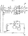
- the air conditioner 100 shown in Fig. 1 is equipped with a compressor, and an outdoor heat exchanger 3 connected to the compressor 1 through a four-way valve 2. Furthermore, an indoor heat exchanger 6 is connected to the outdoor heat exchanger 3 through two mechanical valves 4 and 5, an accumulator 7 is connected to the indoor heat exchanger 6 through the four-way valve 2, and the accumulator 7 is connected to the compressor 1.
- solid-line arrows represent the flow of refrigerant under cooling operation.
- the refrigerant discharged from the compressor 1 passes through the four-way valve 2 and reaches the outdoor heat exchanger 3 to be condensed. Then, the refrigerant thus condensed passes through the mechanical valves 4 and 5 and reaches the indoor heat exchanger 6.
- the indoor heat exchanger 6 the refrigerant is supplied with air blown out from an indoor air blower 6A to be evaporated, and them the refrigerant thus evaporated passes through the four-way valve 2 and the accumulator 7 and returns to the compressor 1.
- a room to be air-conditioned is cooled by the air blown from the indoor air blower 6A.
- Broken line arrows represent the flow of refrigerant under heating operation.
- the refrigerant discharged from the compressor 1 passes through the four-way valve 2 and reaches the indoor heat exchanger 6.
- the indoor heat exchanger 6 the refrigerant is supplied with air blown out from the indoor air blower 6A to be condensed, and then the refrigerant thus condensed passes through the mechanical valves 5 and 4 and reaches the outdoor heat exchanger 3.
- the refrigerant is evaporated, and then passes through the accumulator 7 and returns to the compressor 1.
- the room to be air-conditioned is heated by the air blown from the indoor air blower 6A.
- the total enthalpy heat exchanger 200 comprises a total enthalpy heat-exchanging element 11.
- the total enthalpy heat-exchanging element 11 is constructed as follows. That is, a flat sheet is put on a first corrugated sheet which is folded in the form of bellows, and then a second corrugated sheet which is folded in the form of bellows in a different folding direction to that of the first corrugated sheet is put on the flat sheet. This laminate structure comprising the first corrugated sheet, the flat sheet and the second corrugated sheet is repeated to thereby form the total enthalpy heat-exchanging element 11.
- the total enthalpy heat-exchanging element 11 is supplied with outdoor air and also with exhaust air (indoor air) from a room being air-conditioned.
- the indoor air and the outdoor air thus supplied to the total enthalpy heat-exchanging element 11 are heat-exchanged with each other, and then the outdoor air is supplied to the room being air-conditioned while the indoor air is exhausted to the outside.
- the outdoor air is passed through an air supply duct 12, an air supply chamber 37 and an air supply fan 13, and then reaches the total enthalpy heat-exchanging element 11 through an outdoor air filter 14.
- the outdoor air is passed from the total enthalpy heat-exchanging element 11 through an air supply path 15, a humidifier 16, an air blow-out flap 17 and an air blow-out louver 18 and reaches the room being air-conditioned.
- a humidifying tank 500 is connected to the humidifier 16, and if water is directly supplied to the tank, humidifying water is successively supplied into the humidifier 16.
- the indoor air from the room being air-conditioned passes through a suction grill 21 and then reaches the total enthalpy heat-exchanging element 11. Thereafter, the indoor air passes from the total enthalpy heat-exchanging element 11 through a dumper 22, an exhaust fan 23, an exhaust chamber 38 and an air exhaust duct 24, and then discharged to the outside.
- the dumper 22 freely shuts off the air flow path, and when the air flow path is shut off, the indoor air passing through the suction grill 21 bypasses the total enthalpy heat-exchanging element 11, reaches the exhaust fan 23 through a normal ventilation air flow path 25, and then is discharged through the exhaust chamber 38 and the air exhaust duct 24 to the outside.
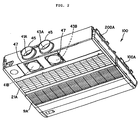
- Fig. 2 is a perspective view showing the air conditioner which is viewed from the lower side.
- the air conditioner 100 comprises an air conditioner main body 100A suspended from the ceiling, and a total enthalpy heat exchanger main body 200A for adjusting the outside air temperature, which is joined to the back side of the air conditioner main body 100A and integrated with the air conditioner main body 100A.
- Air supply duct connection ports 41A to 41C and air exhaust duct connection ports 43A to 43C are formed on plural wall surfaces of the total enthalpy heat exchanger main body 200A. Any one of the air supply duct connection ports 41A to 41C and any one of the air exhaust duct connection ports 43A to 43C are selected, and the air supply duct 12 ( Fig. 3 ) and the air exhaust duct 24 ( Fig. 3 ) are connectable to these selected duct connection ports.
- the air supply duct connection ports 41A to 41C and the air exhaust duct connection ports 43A to 43C are formed on the back surface, lower surface and upper surface of the total enthalpy heat exchanger main body 200A.
- a connecting member 45 is disposed at each of the duct connection ports 41A and 43A formed on the back surface of the total enthalpy heat exchanger main body 200A, and the air supply duct 12 ( Fig. 3 ) and the air exhaust duct 24 ( Fig. 3 ) are connected to these connecting members 45.
- closing members 47 for closing the other duct connection ports 41B, 43B, 41C and 43C are disposed at the duct connection ports 41B, 43B formed on the lower surface of the total enthalpy heat exchanger main body 200A and the duct connection ports 41C and 43C ( Fig. 3 ) formed on the upper surface of the total enthalpy heat exchanger main body 200A.
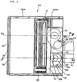
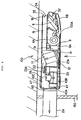
- Fig. 3 is a plan view showing the air conditioner 100 when the upper side panel of the total enthalpy heat exchanger main body 200A is detached
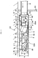
- Fig. 4 is a cross-sectional view taken along A-A line of Fig. 3
- Fig. 5 is a cross-sectional view taken along B-B line of Fig. 3 .
- the indoor heat exchanger 6, the indoor air blower 6A, a drain pan 6B, a box 19 for electrical equipment, etc. are disposed in the air conditioner main body 100A
- a filter 9A is disposed at the suction grill 9.
- indoor air is sucked through the suction grill 9, and passed through the indoor air blower 6A to the indoor heat exchanger 6.
- the indoor air is heat-exchanged with refrigerant in the indoor heat exchanger 6, and then blown out through a blow-out port 32 to the room being air-conditioned.
- the total heat enthalpy heat-exchanging element 11 is disposed in the total enthalpy heat exchanger main body 200A, and the air supply fan 13 and the exhaust fan 23 are arranged at the rear side of the total enthalpy heat-exchanging element 11.
- a partition plate 51 is provided between the air supply fan 13 and the exhaust fan 23 to prevent the contamination between the outdoor air and the indoor air.
- a filter 21A is disposed at the suction grill 21 of the total enthalpy heat exchanger main body 200A. When the total enthalpy heat exchanger main body 200A is driven, the indoor air is sucked through the suction grill 21, and the indoor air reaches the total enthalpy heat-exchanging element 11.
- the indoor air is heat-exchanged with the outdoor air, and then the indoor air is discharged through the exhaust fan 23 to the outside.
- the outdoor air reaches the total enthalpy heat-exchanging element 11 through the air supply fan 13, and it is heat-exchanged with the indoor air in the total enthalpy heat-exchanging element 11. Thereafter, the outdoor air is passed through the air supply path 15, the blow-out louver 18, etc. and then blown out from the blow-out port 34 to the room being air-conditioned.
- the blow-out ports 32, 34 of the respective main bodies 100A, 200A are independently formed of each other.
- the blow-out ports 32 and 34 are disposed to be adjacent to each other so that the air blow out from the air blow-out port of the air conditioner main body 100A and the air blow out from the blow-out port 34 of the total enthalpy heat exchanger main body 200A are freely mixed with each other at the exit of each of the air blow-out ports 32, 34.
- the respective air blow-out ports 32 and 34 are independent of each other, and the air of the total enthalpy heat exchanger main body 200A is prevented from invading into the air conditioner main body 100A in the unit.
- the height H1 of the air conditioner main body 100A is set to be lower than the height H2 of the total enthalpy heat exchanger main body 200A as shown in Fig. 4 , and the air supply path 15 of the total enthalpy heat exchanger main body 200A is disposed above the air conditioner main body 100A located at a lower position.
- the total height of the height of the air supply path 15 and the height H1 of the air conditioner main body 100A is substantially equal to the height H2 of the total enthalpy heat exchanger main body 200A.
- the tip portion of the air supply path 15 is provided with the air blow-out port 34 having substantially the same width as the air supply path 15.
- the full width of the air blow-out port 34 is set to be equal to the full width of the air blow-out port 32 of the air conditioner main body 100A as shown in Fig. 3 .
- a guide vane 35 for guiding air blown out from the air blow-out port 34 to the air blow-out port 32 side of the air conditioner main body 100A is disposed at the air blow-out port of the total enthalpy heat exchanger body 200A as shown in Fig. 3 .
- the air supply fan 13 is provided with a suction port 13A which is designed to face downwardly and blow out air sucked from the suction port 13A toward the total enthalpy heat-exchanging element 11. Furthermore, an air supply chamber 37 intercommunicating with the suction port 13A of the air supply fan 13 is disposed at the total enthalpy heat exchanger main body 200a, and the air supply chamber 37 intercommunicate with the air supply duct connection ports 41A to 41C formed on the back surface, lower surface and upper surface of the total enthalpy heat exchanger main body 200A.
- the air supply fan 13 is disposed so that the suction port 13A of the air supply fan 13 is protruded into the inner space of the air supply chamber 37 to provide substantially equal spaces X at the upper and lower sides of the inner space.
- the spaceX intercommunicates with the air supply duct connection ports 41A to 41C of the total enthalpy heat exchanger main body 200A. Therefore, the outdoor air flows through the air supply duct 12 into the air supply chamber 37, and is sucked into the suction port 13 of the air supply fan 13 through the space X.
- the closing members 47 are disposed at the air supply duct connection ports 41B and 41C to which the air supply duct 12 is not connected, and thus air can be prevented from flowing through the air supply duct connection ports 41B, 41C into the air supply chamber 37.
- the exhaust fan 23 has a suction port 23A formed with being placed face up, and a blow-out port (not shown) for blowing out air sucked from the suction port 23A.
- This air blow-out port is connected to the exhaust chamber 38 intercommunicating with the air exhaust duct connection ports 43A to 43C of the total enthalpy heat exchanger main body 200A. Accordingly, the indoor air from the room to be air-conditioned is heat-exchanged with the outdoor air in the total enthalpy heat-exchanging element 11, and then sucked from the suction port 23A of the exhaust fan 23 into the exhaust chamber 38.
- the indoor air is discharged through the air exhaust duct 24 connected to the exhaust chamber 38 to the outside.
- the closing members 47 are disposed at the air exhaust duct connection ports 43B and 43C to which no air exhaust duct 24 is connected. Therefore, the air is prevented from flowing from the exhaust chamber 38 through the air exhaust duct connection ports 43B and 43C into the room.
- the total enthalpy heat exchanger 200 comprises the air supply chamber 37 intercommunicating with the suction port 13A of the air supply fan 13, and the exhaust chamber 38 intercommunicating with the blow-out port (not shown) of the exhaust fan 23, and the air supply chamber 37 and the exhaust chamber 38 are designed so as to intercommunicate with the air supply duct connection ports 41A to 41C and the air exhaust duct connection ports 43A to 43C formed in the total enthalpy heat exchanger main body 200A, respectively.
- any one of the air supply duct connection ports 41A to 41C and any one of the air exhaust duct connection ports 43A to 43C are arbitrarily selected in accordance with the condition under which the air conditioner 100 is set up, the air supply duct 12 and the air exhaust duct 13 are connected to the air supply duct connection port and the air exhaust duct connection port thus selected.
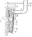
- the ducts 12 and 24 are connected to the duct connection ports 41B and 43B formed on the lower surface of the total enthalpy heat exchanger main body 200A through elbows 71 and 73 respectively as shown in Figs. 6 and 7 , whereby the ducts 12 and 24 can be drawn out backwardly while avoiding the beam 300. Accordingly, not only the draw-out work of the ducts can be easily performed, but also the air conditioner 100 can be set up in proximity to the wall surface 150, so that the appearance of the arrangement of the air conditioner looks good.
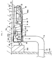
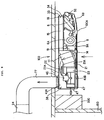
- the ducts 12 and 24 are connected to the duct connection ports 41C and 43C formed on the upper surface of the total enthalpy heat exchanger main body 200A through elbows 75 and 77 as shown in Figs. 8 and 9 , whereby the ducts 12 and 24 can be also drawn out backwardly while avoiding the beam 300.
- the air conditioner 100 can be set up in proximity to the wall surface 150, but also the ducts can be arranged to pass under the roof, so that the ducts can be prevented from being exposed to the room and thus the appearance of the arrangement of the air conditioner looks good.
- the outdoor air flows through the air supply duct 12 into the air supply chamber 37, and sucked through the space X of the air supply chamber 37 into the suction port 13 of the air supply fan 13. Thereafter, the outdoor air reaches the total enthalpy heat-exchanging element 11, and it is heat-exchanged with the indoor air in the total enthalpy heat-exchanging element 11 and then supplied to the room. Furthermore, the indoor air from the room to be air-conditioned is heat-exchanged with the outdoor air in the total enthalpy heat-exchanging element 11, sucked from the exhaust fan 23 into the exhaust chamber 38, and then discharged to the outside through the air exhaust duct 24 connected to the exhaust chamber 38. Accordingly, the total enthalpy heat exchanger 200 can sufficient exhibit its ventilation function.
- the air conditioner is equipped with the air supply chamber 37 intercommunicating with the suction port 13A of the air supply fan 13 and the exhaust chamber 38 intercommunicating with the blow-out port of the exhaust fan 23, and the air supply chamber 37 and the exhaust chamber 38 are designed so as to be connectable to the plural duct connection ports 41A to 41C and 43A to 43C. Therefore, when each of the ducts 12 and 24 is connected to one of these duct connection ports, any duct connection port can be selected. Accordingly, in accordance with the condition under which the ceiling suspended type air conditioner 100 is set up, each of the ducts 12 and 24 can be connected to the optimal duct connection port, and the degree of freedom for the setup work of the air conditioner 100 can be enhanced.
- the closing members 47 are disposed at the duct connection ports to which the ducts 12, 24 are not connected, and thus leakage of air through the duct connection ports concerned can be prevented.
- the air supply duct connection ports 41A to 41C and the air exhaust duct connection ports 43A to 43C are formed on the upper surface, lower surface and back surface of the total enthalpy heat exchanger main body 200A.
- each of these duct connection ports may be formed on any surface of the total enthalpy heat exchanger main body 200A insofar as each of the duct connection ports intercommunicates with each of the chambers 37 and 38.
- the air supply duct 12 and the air exhaust duct 24 are connected to the same surface of the total enthalpy heat exchanger main body 200A, however, the present invention is not limited to this mode. That is, these ducts 12 and 24 may be connected to different surfaces of the total enthalpy heat exchanger main body 200A.
Landscapes
- Engineering & Computer Science (AREA)
- Chemical & Material Sciences (AREA)
- Combustion & Propulsion (AREA)
- Mechanical Engineering (AREA)
- General Engineering & Computer Science (AREA)
- Physics & Mathematics (AREA)
- Thermal Sciences (AREA)
- Air Filters, Heat-Exchange Apparatuses, And Housings Of Air-Conditioning Units (AREA)
- Central Air Conditioning (AREA)
- Duct Arrangements (AREA)
Applications Claiming Priority (1)
| Application Number | Priority Date | Filing Date | Title |
|---|---|---|---|
| JP2004257296A JP4568058B2 (ja) | 2004-09-03 | 2004-09-03 | 天吊型空気調和装置 |
Publications (3)
| Publication Number | Publication Date |
|---|---|
| EP1632726A2 EP1632726A2 (en) | 2006-03-08 |
| EP1632726A3 EP1632726A3 (en) | 2010-08-25 |
| EP1632726B1 true EP1632726B1 (en) | 2016-08-10 |
Family
ID=35431234
Family Applications (1)
| Application Number | Title | Priority Date | Filing Date |
|---|---|---|---|
| EP05017877.1A Expired - Lifetime EP1632726B1 (en) | 2004-09-03 | 2005-08-17 | Ceiling suspended type air conditioner |
Country Status (4)
| Country | Link |
|---|---|
| EP (1) | EP1632726B1 (ja) |
| JP (1) | JP4568058B2 (ja) |
| KR (1) | KR100699398B1 (ja) |
| CN (1) | CN100351578C (ja) |
Cited By (1)
| Publication number | Priority date | Publication date | Assignee | Title |
|---|---|---|---|---|
| TWI772765B (zh) * | 2020-03-23 | 2022-08-01 | 新加坡商特靈新加坡企業私人有限公司 | 換熱系統 |
Families Citing this family (10)
| Publication number | Priority date | Publication date | Assignee | Title |
|---|---|---|---|---|
| FI117726B (fi) * | 2005-04-12 | 2007-01-31 | Halton Oy | Liitäntälaitteisto ilmakanavaan ja menetelmä laitteiston ilmakanavaan asennuksessa |
| EP1891981A3 (en) * | 2006-08-25 | 2009-10-21 | Sanyo Electric Co., Ltd. | Air conditioner, air conditioning system, air filtering apparatus and air filtering system |
| EP1892483B1 (en) * | 2006-08-25 | 2012-08-08 | Sanyo Electric Co., Ltd. | Air conditioner and method of controlling the same |
| ITBG20120043A1 (it) * | 2012-09-12 | 2014-03-13 | Massimo Silvestri | Apparecchio combinato di trattamento aria e ventilazione meccanica con recupero di energia, per singolo ambiente |
| KR101407888B1 (ko) * | 2013-10-11 | 2014-06-30 | 주식회사 세기공조 | 배기 열회수기를 부착하고 바이패스 기능을 갖춘 공기조화기 |
| FR3014548B1 (fr) * | 2013-12-11 | 2018-11-30 | Starklab | Dispositf de production d'un flux d'air dont la temperature est controlee par echange thermique avec un liquide et avec mise en contact direct du flux d'air et du liquide |
| WO2016194261A1 (ja) * | 2015-05-29 | 2016-12-08 | 三菱電機株式会社 | 熱交換型換気装置 |
| JP6774704B2 (ja) * | 2015-12-10 | 2020-10-28 | ハイウェイ・トール・システム株式会社 | 空調システム |
| CN106958869A (zh) * | 2017-04-29 | 2017-07-18 | 山东格瑞德集团有限公司 | 吊顶式空气处理机组 |
| CN108194985A (zh) * | 2018-01-12 | 2018-06-22 | 青岛海尔空调器有限总公司 | 用于空调室内机的净化模块和空调室内机 |
Citations (2)
| Publication number | Priority date | Publication date | Assignee | Title |
|---|---|---|---|---|
| JPS6317329A (ja) * | 1986-07-08 | 1988-01-25 | Matsushita Seiko Co Ltd | 空調換気ユニット |
| JPS6332229U (ja) * | 1986-08-19 | 1988-03-02 |
Family Cites Families (18)
| Publication number | Priority date | Publication date | Assignee | Title |
|---|---|---|---|---|
| JPS62268943A (ja) * | 1986-05-16 | 1987-11-21 | Matsushita Seiko Co Ltd | 空気調和機 |
| JPS62299637A (ja) * | 1986-06-19 | 1987-12-26 | Matsushita Seiko Co Ltd | 天井埋込形空気調和機 |
| JPH0275840A (ja) * | 1988-09-09 | 1990-03-15 | Matsushita Seiko Co Ltd | 換気空調装置 |
| JPH0743154B2 (ja) * | 1988-12-28 | 1995-05-15 | 松下精工株式会社 | 換気空調ユニット |
| JPH0397141U (ja) * | 1990-01-23 | 1991-10-04 | ||
| DE4002560C2 (de) * | 1990-01-30 | 1995-07-20 | Stiebel Eltron Gmbh & Co Kg | Klimagerät |
| JP3101103B2 (ja) * | 1992-11-16 | 2000-10-23 | 株式会社大林組 | 空気調和機の利用側ユニット |
| JPH0861733A (ja) * | 1994-08-26 | 1996-03-08 | Daikin Ind Ltd | 熱交換換気装置 |
| JP3519482B2 (ja) * | 1995-02-20 | 2004-04-12 | 三菱電機株式会社 | 換気システム、及び、換気ユニット |
| CN1152697A (zh) * | 1995-12-22 | 1997-06-25 | 黄信璁 | 吊挂式空调送风机装置的改进结构 |
| JP3503369B2 (ja) * | 1996-11-19 | 2004-03-02 | 三菱電機株式会社 | 熱交換換気装置 |
| JPH10274425A (ja) * | 1997-03-31 | 1998-10-13 | Daikin Ind Ltd | 換気機能付き空気調和機及びその空気調和機を用いた換気空調システム |
| KR200241498Y1 (ko) * | 1999-06-30 | 2001-09-29 | 윤종용 | 천정형 에어컨의 외부공기 도입구조 |
| JP3449551B2 (ja) * | 2000-05-23 | 2003-09-22 | 木村工機株式会社 | 直近空調ユニット |
| JP4233313B2 (ja) * | 2001-11-22 | 2009-03-04 | 昭和電工株式会社 | 換気兼熱交換装置および空調システム |
| KR100413271B1 (ko) * | 2001-11-23 | 2004-01-03 | 주식회사 두우종합기술단 | 닥트연결이 자유로운 공기조화기 및 이를 이용한공기조화기 닥트연결방법 |
| JP3789807B2 (ja) | 2001-11-30 | 2006-06-28 | 三洋電機株式会社 | 浴室暖房機 |
| EP1429081B9 (de) * | 2002-12-12 | 2007-05-09 | TROX GmbH | Belüftungssystem zur Raumbelüftung |
-
2004
- 2004-09-03 JP JP2004257296A patent/JP4568058B2/ja not_active Expired - Fee Related
-
2005
- 2005-08-17 EP EP05017877.1A patent/EP1632726B1/en not_active Expired - Lifetime
- 2005-08-29 CN CNB2005100923385A patent/CN100351578C/zh not_active Expired - Fee Related
- 2005-09-02 KR KR1020050081482A patent/KR100699398B1/ko not_active Expired - Fee Related
Patent Citations (2)
| Publication number | Priority date | Publication date | Assignee | Title |
|---|---|---|---|---|
| JPS6317329A (ja) * | 1986-07-08 | 1988-01-25 | Matsushita Seiko Co Ltd | 空調換気ユニット |
| JPS6332229U (ja) * | 1986-08-19 | 1988-03-02 |
Cited By (1)
| Publication number | Priority date | Publication date | Assignee | Title |
|---|---|---|---|---|
| TWI772765B (zh) * | 2020-03-23 | 2022-08-01 | 新加坡商特靈新加坡企業私人有限公司 | 換熱系統 |
Also Published As
| Publication number | Publication date |
|---|---|
| EP1632726A3 (en) | 2010-08-25 |
| KR100699398B1 (ko) | 2007-03-27 |
| JP2006071226A (ja) | 2006-03-16 |
| CN1743743A (zh) | 2006-03-08 |
| KR20060050950A (ko) | 2006-05-19 |
| JP4568058B2 (ja) | 2010-10-27 |
| CN100351578C (zh) | 2007-11-28 |
| EP1632726A2 (en) | 2006-03-08 |
Similar Documents
| Publication | Publication Date | Title |
|---|---|---|
| JP4565936B2 (ja) | 空気調和装置 | |
| EP1632726B1 (en) | Ceiling suspended type air conditioner | |
| US12196435B2 (en) | Window air conditioner | |
| JP2002162067A (ja) | 空気調和装置 | |
| JP4036860B2 (ja) | 空気調和機の室内機 | |
| EP2113723A2 (en) | Ventilating apparatus | |
| JP2018123999A (ja) | 風路切替ダンパ、ファンコイルユニットおよび空気調和システム | |
| JP6211675B1 (ja) | 全館空調システム | |
| JP5492624B2 (ja) | 空気調和機 | |
| KR102822626B1 (ko) | 모듈공조기, 및 공조시스템 | |
| EP1710514B1 (en) | Ceiling-hanged air conditioner | |
| WO2020250563A1 (ja) | 天井埋込型の室内機、及び空気調和装置 | |
| JP3855393B2 (ja) | 空気調和装置 | |
| JP4016988B2 (ja) | 農産業用空気熱源ヒートポンプ式空調機 | |
| KR101192002B1 (ko) | 가습 환기 장치 및 이를 갖춘 공기 조화기 | |
| JP4646611B2 (ja) | 空気調和装置 | |
| JP2616308B2 (ja) | 空気調和ユニット | |
| JP7227516B2 (ja) | 換気装置 | |
| CN113757812B (zh) | 窗式空调器 | |
| JP3726796B2 (ja) | 壁設置用一体形エアコン | |
| JP3811953B2 (ja) | 農産業用空気熱源ヒートポンプ式空調機 | |
| JP2005282949A (ja) | 空気調和装置 | |
| JP2006071214A (ja) | 空気調和装置及び空気調和装置の制御方法 | |
| JPH0749873B2 (ja) | 一体型集中空調ユニット | |
| JP2007024415A (ja) | 熱交換型換気装置、この熱交換型換気装置を備える空調システムおよびこの空調システムを備えた建物 |
Legal Events
| Date | Code | Title | Description |
|---|---|---|---|
| PUAI | Public reference made under article 153(3) epc to a published international application that has entered the european phase |
Free format text: ORIGINAL CODE: 0009012 |
|
| 17P | Request for examination filed |
Effective date: 20050817 |
|
| AK | Designated contracting states |
Kind code of ref document: A2 Designated state(s): AT BE BG CH CY CZ DE DK EE ES FI FR GB GR HU IE IS IT LI LT LU LV MC NL PL PT RO SE SI SK TR |
|
| AX | Request for extension of the european patent |
Extension state: AL BA HR MK YU |
|
| PUAL | Search report despatched |
Free format text: ORIGINAL CODE: 0009013 |
|
| AK | Designated contracting states |
Kind code of ref document: A3 Designated state(s): AT BE BG CH CY CZ DE DK EE ES FI FR GB GR HU IE IS IT LI LT LU LV MC NL PL PT RO SE SI SK TR |
|
| AX | Request for extension of the european patent |
Extension state: AL BA HR MK YU |
|
| RIC1 | Information provided on ipc code assigned before grant |
Ipc: F24F 13/32 20060101ALI20100720BHEP Ipc: F24F 1/00 20060101AFI20051207BHEP Ipc: F24F 12/00 20060101ALI20100720BHEP |
|
| AKX | Designation fees paid |
Designated state(s): DE FR GB IT |
|
| 17Q | First examination report despatched |
Effective date: 20121023 |
|
| GRAP | Despatch of communication of intention to grant a patent |
Free format text: ORIGINAL CODE: EPIDOSNIGR1 |
|
| INTG | Intention to grant announced |
Effective date: 20160302 |
|
| GRAS | Grant fee paid |
Free format text: ORIGINAL CODE: EPIDOSNIGR3 |
|
| GRAA | (expected) grant |
Free format text: ORIGINAL CODE: 0009210 |
|
| AK | Designated contracting states |
Kind code of ref document: B1 Designated state(s): DE FR GB IT |
|
| REG | Reference to a national code |
Ref country code: GB Ref legal event code: FG4D |
|
| REG | Reference to a national code |
Ref country code: DE Ref legal event code: R096 Ref document number: 602005049905 Country of ref document: DE |
|
| PG25 | Lapsed in a contracting state [announced via postgrant information from national office to epo] |
Ref country code: IT Free format text: LAPSE BECAUSE OF FAILURE TO SUBMIT A TRANSLATION OF THE DESCRIPTION OR TO PAY THE FEE WITHIN THE PRESCRIBED TIME-LIMIT Effective date: 20160810 |
|
| REG | Reference to a national code |
Ref country code: DE Ref legal event code: R097 Ref document number: 602005049905 Country of ref document: DE |
|
| PLBE | No opposition filed within time limit |
Free format text: ORIGINAL CODE: 0009261 |
|
| STAA | Information on the status of an ep patent application or granted ep patent |
Free format text: STATUS: NO OPPOSITION FILED WITHIN TIME LIMIT |
|
| REG | Reference to a national code |
Ref country code: FR Ref legal event code: ST Effective date: 20170531 |
|
| 26N | No opposition filed |
Effective date: 20170511 |
|
| GBPC | Gb: european patent ceased through non-payment of renewal fee |
Effective date: 20161110 |
|
| PG25 | Lapsed in a contracting state [announced via postgrant information from national office to epo] |
Ref country code: FR Free format text: LAPSE BECAUSE OF NON-PAYMENT OF DUE FEES Effective date: 20161010 |
|
| PG25 | Lapsed in a contracting state [announced via postgrant information from national office to epo] |
Ref country code: GB Free format text: LAPSE BECAUSE OF NON-PAYMENT OF DUE FEES Effective date: 20161110 |
|
| PGFP | Annual fee paid to national office [announced via postgrant information from national office to epo] |
Ref country code: DE Payment date: 20180823 Year of fee payment: 14 |
|
| REG | Reference to a national code |
Ref country code: DE Ref legal event code: R119 Ref document number: 602005049905 Country of ref document: DE |
|
| PG25 | Lapsed in a contracting state [announced via postgrant information from national office to epo] |
Ref country code: DE Free format text: LAPSE BECAUSE OF NON-PAYMENT OF DUE FEES Effective date: 20200303 |