WO2020250563A1 - 天井埋込型の室内機、及び空気調和装置 - Google Patents
天井埋込型の室内機、及び空気調和装置 Download PDFInfo
- Publication number
- WO2020250563A1 WO2020250563A1 PCT/JP2020/016327 JP2020016327W WO2020250563A1 WO 2020250563 A1 WO2020250563 A1 WO 2020250563A1 JP 2020016327 W JP2020016327 W JP 2020016327W WO 2020250563 A1 WO2020250563 A1 WO 2020250563A1
- Authority
- WO
- WIPO (PCT)
- Prior art keywords
- casing
- ceiling
- air
- indoor unit
- indoor
- Prior art date
Links
Images


Classifications
-
- F—MECHANICAL ENGINEERING; LIGHTING; HEATING; WEAPONS; BLASTING
- F24—HEATING; RANGES; VENTILATING
- F24F—AIR-CONDITIONING; AIR-HUMIDIFICATION; VENTILATION; USE OF AIR CURRENTS FOR SCREENING
- F24F1/00—Room units for air-conditioning, e.g. separate or self-contained units or units receiving primary air from a central station
- F24F1/0007—Indoor units, e.g. fan coil units
- F24F1/00075—Indoor units, e.g. fan coil units receiving air from a central station
-
- F—MECHANICAL ENGINEERING; LIGHTING; HEATING; WEAPONS; BLASTING
- F24—HEATING; RANGES; VENTILATING
- F24F—AIR-CONDITIONING; AIR-HUMIDIFICATION; VENTILATION; USE OF AIR CURRENTS FOR SCREENING
- F24F1/00—Room units for air-conditioning, e.g. separate or self-contained units or units receiving primary air from a central station
- F24F1/0007—Indoor units, e.g. fan coil units
- F24F1/0011—Indoor units, e.g. fan coil units characterised by air outlets
-
- F—MECHANICAL ENGINEERING; LIGHTING; HEATING; WEAPONS; BLASTING
- F24—HEATING; RANGES; VENTILATING
- F24F—AIR-CONDITIONING; AIR-HUMIDIFICATION; VENTILATION; USE OF AIR CURRENTS FOR SCREENING
- F24F1/00—Room units for air-conditioning, e.g. separate or self-contained units or units receiving primary air from a central station
- F24F1/0007—Indoor units, e.g. fan coil units
- F24F1/0018—Indoor units, e.g. fan coil units characterised by fans
- F24F1/0025—Cross-flow or tangential fans
-
- F—MECHANICAL ENGINEERING; LIGHTING; HEATING; WEAPONS; BLASTING
- F24—HEATING; RANGES; VENTILATING
- F24F—AIR-CONDITIONING; AIR-HUMIDIFICATION; VENTILATION; USE OF AIR CURRENTS FOR SCREENING
- F24F1/00—Room units for air-conditioning, e.g. separate or self-contained units or units receiving primary air from a central station
- F24F1/0007—Indoor units, e.g. fan coil units
- F24F1/0035—Indoor units, e.g. fan coil units characterised by introduction of outside air to the room
-
- F—MECHANICAL ENGINEERING; LIGHTING; HEATING; WEAPONS; BLASTING
- F24—HEATING; RANGES; VENTILATING
- F24F—AIR-CONDITIONING; AIR-HUMIDIFICATION; VENTILATION; USE OF AIR CURRENTS FOR SCREENING
- F24F1/00—Room units for air-conditioning, e.g. separate or self-contained units or units receiving primary air from a central station
- F24F1/0007—Indoor units, e.g. fan coil units
- F24F1/0043—Indoor units, e.g. fan coil units characterised by mounting arrangements
- F24F1/0047—Indoor units, e.g. fan coil units characterised by mounting arrangements mounted in the ceiling or at the ceiling
-
- F—MECHANICAL ENGINEERING; LIGHTING; HEATING; WEAPONS; BLASTING
- F24—HEATING; RANGES; VENTILATING
- F24F—AIR-CONDITIONING; AIR-HUMIDIFICATION; VENTILATION; USE OF AIR CURRENTS FOR SCREENING
- F24F1/00—Room units for air-conditioning, e.g. separate or self-contained units or units receiving primary air from a central station
- F24F1/0007—Indoor units, e.g. fan coil units
- F24F1/0059—Indoor units, e.g. fan coil units characterised by heat exchangers
- F24F1/0063—Indoor units, e.g. fan coil units characterised by heat exchangers by the mounting or arrangement of the heat exchangers
-
- F—MECHANICAL ENGINEERING; LIGHTING; HEATING; WEAPONS; BLASTING
- F24—HEATING; RANGES; VENTILATING
- F24F—AIR-CONDITIONING; AIR-HUMIDIFICATION; VENTILATION; USE OF AIR CURRENTS FOR SCREENING
- F24F13/00—Details common to, or for air-conditioning, air-humidification, ventilation or use of air currents for screening
- F24F13/20—Casings or covers
-
- F—MECHANICAL ENGINEERING; LIGHTING; HEATING; WEAPONS; BLASTING
- F24—HEATING; RANGES; VENTILATING
- F24F—AIR-CONDITIONING; AIR-HUMIDIFICATION; VENTILATION; USE OF AIR CURRENTS FOR SCREENING
- F24F1/00—Room units for air-conditioning, e.g. separate or self-contained units or units receiving primary air from a central station
- F24F1/0007—Indoor units, e.g. fan coil units
- F24F1/0071—Indoor units, e.g. fan coil units with means for purifying supplied air
- F24F1/0073—Indoor units, e.g. fan coil units with means for purifying supplied air characterised by the mounting or arrangement of filters
-
- F—MECHANICAL ENGINEERING; LIGHTING; HEATING; WEAPONS; BLASTING
- F24—HEATING; RANGES; VENTILATING
- F24F—AIR-CONDITIONING; AIR-HUMIDIFICATION; VENTILATION; USE OF AIR CURRENTS FOR SCREENING
- F24F13/00—Details common to, or for air-conditioning, air-humidification, ventilation or use of air currents for screening
- F24F13/30—Arrangement or mounting of heat-exchangers
-
- F—MECHANICAL ENGINEERING; LIGHTING; HEATING; WEAPONS; BLASTING
- F24—HEATING; RANGES; VENTILATING
- F24F—AIR-CONDITIONING; AIR-HUMIDIFICATION; VENTILATION; USE OF AIR CURRENTS FOR SCREENING
- F24F3/00—Air-conditioning systems in which conditioned primary air is supplied from one or more central stations to distributing units in the rooms or spaces where it may receive secondary treatment; Apparatus specially designed for such systems
- F24F3/06—Air-conditioning systems in which conditioned primary air is supplied from one or more central stations to distributing units in the rooms or spaces where it may receive secondary treatment; Apparatus specially designed for such systems characterised by the arrangements for the supply of heat-exchange fluid for the subsequent treatment of primary air in the room units
- F24F3/065—Air-conditioning systems in which conditioned primary air is supplied from one or more central stations to distributing units in the rooms or spaces where it may receive secondary treatment; Apparatus specially designed for such systems characterised by the arrangements for the supply of heat-exchange fluid for the subsequent treatment of primary air in the room units with a plurality of evaporators or condensers
Definitions
- This disclosure relates to a ceiling-embedded indoor unit and an air conditioner.
- An air conditioner equipped with a ceiling-embedded indoor unit is known.
- a heat exchanger and a blower are housed inside a casing installed behind the ceiling.
- An air outlet that supplies air that has passed through the heat exchanger to the indoor space is formed on the lower surface of the casing.
- the panel located on the lower surface of the casing is exposed in the indoor space.
- An object of the present disclosure is to reduce the area of the panel of the indoor unit.
- the first aspect is a ceiling-embedded indoor unit for an air conditioner including a casing (40) and a blower (32) and a heat exchanger (33) arranged inside the casing (40).
- the casing (40) is arranged in the space (6) on the back side of the ceiling (C), and is provided in a casing main body (40a) whose lower side is open and an open portion on the lower side of the casing main body (40a).
- a panel (50) provided and exposed to the air-conditioned space (5) is provided, and the panel (50) is formed with outlets (51,52) for supplying air to the air-conditioned space (5).
- the casing body (40a) is formed with suction ports (46,47) for sucking air, and each of the outlet (51,52), the blower (32), and the heat exchanger (33). At least some of them overlap each other in the vertical direction.
- each of the outlet (51,52), the blower (32), and the heat exchanger (33) is vertically overlapped. Therefore, the casing (40) can be reduced in the horizontal direction, and the panel (50) can be reduced in the horizontal direction.
- the casing (40) has a long side extending along the ceiling (C) and a short side shorter than the long side.
- a panel (50) extending along the ceiling (C) can be formed.
- the total area including the outlet (51,52) on the lower surface of the panel (50) is S1
- the total opening area of the outlet (51,52) is S2. Then, the total opening area S2 is 20% or more of the total area S1.
- the opening area of the outlet (51,52) with respect to the panel (50) is relatively large.
- a fourth aspect is, in the second or third aspect, the blower (32) is a cross-flow fan extending in the longitudinal direction of the casing (40).
- the dead space in the casing (40) can be reduced.
- the suction port (46,47) is formed on at least one side plate (41,42) of the casing body (40a).
- the “side plate” here means a plate that forms the left, right, front and rear surfaces, and does not include the plate that forms the upper and lower surfaces.
- the suction port (46,47) can be secured on the side plate (41,42) without forming the suction port (46,47) on the upper plate of the casing main body (40a).
- the suction port (46,47) is formed on each of the two side plates (41,42) of the casing body (40a) facing each other.
- suction ports (46,47) can be secured on the side plates (41,42) on both sides of the casing body (40a), respectively.
- a seventh aspect is, in any one of the first to sixth aspects, the heat exchanger (33) is arranged near the first side plate (41) of the casing body (40a). It has an exchange part (33A) and a second heat exchange part (33B) arranged closer to the second side plate (42) facing the first side plate (41) of the casing body (40a).
- the first heat exchange section (33A) and the second heat exchange section (33B) are arranged so as to be inclined so that the distance between them increases toward the bottom.
- the heat exchange section (33A, 33B) can be arranged so as to correspond to each suction port (46,47) of each side plate (41,42).
- the heat transfer area can be expanded by inclining the heat exchange sections (33A, 33B).
- An eighth aspect in any one of the first to seventh aspects, comprises a filter (71,72) that captures dust in the air sucked into the suction port (46,47), said panel (50). Is formed with slits (54,55) that pull the filter (71,72) out of the casing (40).
- the filter (71,72) can be inserted and removed without removing the panel (50) from the casing body (40a).
- the ninth aspect is an air conditioner including an outdoor unit (20) and a ceiling-embedded indoor unit (30) of any one of the first to eight.
- FIG. 1 is a piping system diagram showing the overall configuration of the air conditioner according to the embodiment.
- FIG. 2 is an enlarged perspective view of a part of the internal structure of the system ceiling.
- FIG. 3 is a perspective view of a part of the system ceiling as viewed from the indoor space side.
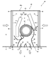
- FIG. 4 is a vertical sectional view of the indoor unit.
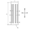
- FIG. 5 is a bottom view of the ceiling panel of the indoor unit.
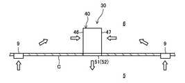
- FIG. 6 is a schematic configuration diagram of an indoor unit showing the air flow in the indoor space and the attic space.
- FIG. 7 is a diagram corresponding to FIG. 4, showing a state in which a part of the filter is pulled out.
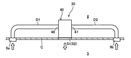
- FIG. 8 is a diagram corresponding to FIG. 6 of the indoor unit according to the first modification.
- FIG. 9 is a schematic configuration diagram showing the internal structure of the indoor unit according to the second modification.
- the air conditioner (10) of the embodiment regulates the temperature of the air in the air-conditioned space (5).
- the air conditioner (10) is applied to buildings and the like.
- the air-conditioned space (5) is an indoor space.
- the air conditioner (10) has an outdoor unit (20) and at least one indoor unit (30).
- the air conditioner (10) of this example is configured as a so-called multi-type having a plurality of indoor units (30).
- the indoor unit (30) is a ceiling-embedded type.
- the outdoor unit (20) is installed outdoors.
- the indoor unit (30) and the outdoor unit (20) are connected to each other via a gas connecting pipe (12) and a liquid connecting pipe (13).
- the air conditioner (10) includes a refrigerant circuit (11).
- the refrigerant circuit (11) is filled with the refrigerant.
- the refrigeration cycle is performed by circulating the refrigerant.
- the outdoor unit (20) has an outdoor circuit (21) and an outdoor fan (22).
- Each indoor unit (30) has an indoor circuit (31) and an indoor fan (32).
- the refrigerant circuit (11) includes an outdoor circuit (21), an indoor circuit (31), and connecting pipes (12, 13) connecting them to each other.
- the outdoor circuit (21) includes a compressor (23), an outdoor heat exchanger (24), an outdoor expansion valve (25), and a four-way switching valve (26).
- the compressor (23) compresses the refrigerant and discharges the compressed refrigerant.
- the outdoor heat exchanger (24) exchanges heat between the outdoor air carried by the outdoor fan (22) and the refrigerant.
- the outdoor heat exchanger (24) is a fin and tube type.
- the outdoor expansion valve (25) is a pressure reducing mechanism for reducing the pressure of the refrigerant.
- the outdoor expansion valve (25) is, for example, an electronic expansion valve.
- the four-way switching valve (26) is a flow path switching mechanism for switching between the first refrigeration cycle (cooling cycle) and the second refrigeration cycle (heating cycle).
- the four-way switching valve (26) switches between a first state (the state shown by the solid line in FIG. 1) and a second state (the state shown by the broken line in FIG. 1).
- Each indoor circuit (31) has an indoor heat exchanger (33) and an indoor expansion valve (34).
- the indoor heat exchanger (33) exchanges heat between the indoor air conveyed by the indoor fan and the refrigerant.
- the indoor heat exchanger (33) is a fin and tube type.
- the indoor expansion valve (34) is a pressure reducing mechanism for reducing the pressure of the refrigerant.
- the indoor expansion valve (34) is, for example, an electronic expansion valve.
- the four-way switching valve (26) is in the first state, and the first refrigeration cycle is performed.
- the refrigerant compressed by the compressor (23) dissipates heat in the outdoor heat exchanger (24), is depressurized by the indoor expansion valve (34), and evaporates in the indoor heat exchanger (33).
- the four-way switching valve (26) is in the second state, and the second refrigeration cycle is performed.
- the refrigerant compressed by the compressor (23) dissipates heat in the indoor heat exchanger (33), is depressurized by the outdoor expansion valve (25), and evaporates in the outdoor heat exchanger (24).
- the indoor unit (30) is applied to the system ceiling (C).
- the system ceiling (C) is a so-called line type.
- the system ceiling (C) has a plurality of bars (B1, B2) arranged in a grid pattern and a ceiling wall (W) fitted between the bars (B1, B2). ..
- the plurality of bars (B1, B2) have a plurality of first bars (B1) and a plurality of second bars (B2).
- the first bar (B1) extends in the front-rear direction.
- the plurality of first bars (B1) are arranged in the left-right direction in a state parallel to each other.
- the second bar (B2) extends in the left-right direction.
- the plurality of second bars (B2) are arranged in the front-rear direction in a state parallel to each other.
- the first bar (B1) and the second bar (B2) are orthogonal to each other.
- a lattice structure is composed of a plurality of first bars (B1) and a plurality of second bars (B2).
- the first bar (B1) has an inverted T-shaped vertical cross section. In other words, at the lower end of the first bar (B1), convex portions (7) protruding on both sides in the width direction are formed.
- the system ceiling (C) has hanging bolts and fixing brackets (not shown).
- the hanging bolts are secured to the slab above the system ceiling.
- the first bar (B1) and the second bar (B2) are supported by the lower end of the hanging bolt via the fixing bracket.
- a first opening (O1) and a second opening (O2) are formed between the plurality of first bars (B1) and the plurality of second bars (B2).
- the left and right width of the first opening (O1) is smaller than the left and right width of the second opening.
- the plurality of first bars (B1) have a plurality of pairs of first bars (B1) (line bars (LB)) that are relatively close to each other.
- a first opening (O1) is formed between these pair of first bars (B1).
- the ceiling wall (W) is fitted into each second opening (O2).
- a ceiling wall (W) is fitted into each first opening (O1).
- the ceiling wall (W) is installed on the upper surface of each convex portion (7) of the first bar (B1) and the second bar (B2).
- An attic space (6) is formed on the back side (upper side) of the ceiling wall (W) of the system ceiling (C).
- An indoor space (5) is formed on the front side (lower side) of the ceiling wall (W) of the system ceiling.
- the lighting device (8) is fitted into a part of the first openings (O1) of the plurality of first openings (O1) (see FIG. 3).
- the lighting device (8) is installed on the upper surface of each convex portion (7) of the first bar (B1) and the second bar (B2).
- the illuminator (8) is formed in a substantially rectangular shape extending along a pair of line bars (LB).
- the casing (40) (strictly speaking, the casing body (40a)) of the indoor unit (30) is fitted into the first opening (O1) of a part of the plurality of first openings (O1).
- the casing body (40a) is installed on the upper surface of each convex portion (7) of the first bar (B1) and the second bar (B2).
- the casing body (40a) extends along a pair of line bars (LB).
- the lighting device (8) and the indoor unit (30) are arranged linearly in the longitudinal direction of these. This gives the impression that the appearance of the ceiling surface is neat.
- the indoor unit (30) will be described with reference to FIGS. 2 to 5.
- the indoor unit (30) is installed in the first opening (O1) of the system ceiling (C).
- the indoor unit (30) includes a casing (40), an indoor fan (32), an indoor heat exchanger (33), a drain pan (35,36), a flow path forming member (60), and a filter (71, 72) and.
- the casing (40) has a casing main body (40a) whose lower side is open, and a ceiling panel (50) provided in the lower open portion of the casing main body (40a).
- An air passage (P) through which air flows is formed inside the casing (40).
- the casing (40) is formed oblong along the system ceiling (C).
- the casing body (40a) is arranged in the attic space (6).
- the ceiling panel (50) is exposed to the indoor space (5) so as to form a ceiling surface.
- the casing body (40a) is formed in a hollow box shape having a long side extending along the ceiling and a short side shorter than the long side. Specifically, the casing body (40a) is formed in an elongated rectangular parallelepiped shape extending in the longitudinal direction of the first bar (B1).
- the casing body (40a) has four side plates (41,42,43,44) and one top plate (45).
- the top plate (45) is located above the casing (40).
- the four side plates are composed of a first side plate (41), a second side plate (42), a third side plate (43), and a fourth side plate (44).
- the first side plate (41) is located on the left side of the casing (40).
- the second side plate (42) is located on the right side of the casing (40).
- the third side plate (43) is located on the front side of the casing (40).
- the fourth side plate (44) is located behind the casing (40).
- the first side plate (41) and the second side plate (42) are side plates along the long side of the casing (40).
- the first side plate (41) and the second side plate (42) face each other.
- the first side plate (41) and the second side plate (42) extend in the longitudinal direction of the first bar (B1) along the first bar (B1).
- the third side plate (43) and the fourth side plate (44) are side plates along the short side of the casing (40).
- the third side plate (43) and the fourth side plate (44) extend in the longitudinal direction of the second
- the casing main body (40a) is formed with a first suction port (46) and a second suction port (47).
- the indoor air in the indoor space (5) is sucked into the first suction port (46) and the second suction port (47) through the ventilation holes (9) and the attic space (6), which will be described in detail later.
- the first suction port (46) is formed on the first side plate (41).
- the first suction port (46) is formed in a rectangular shape along the outer edge of the first side plate (41).
- the first suction port (46) extends from the vicinity of the upper end to the vicinity of the lower end of the first side plate (41).
- the first suction port (46) extends in the longitudinal direction of the casing (40) from the vicinity of the front end to the vicinity of the rear end of the first side plate (41).
- the second suction port (47) is formed on the second side plate (42).
- the second suction port (47) is formed in a rectangular shape along the outer edge of the second side plate (42).
- the second suction port (47) extends from the vicinity of the upper end to the vicinity of the lower end of the second side plate (42).
- the second suction port (47) extends in the longitudinal direction of the casing (40) from the vicinity of the front end to the vicinity of the rear end of the second side plate (42).
- the ceiling panel (50) constitutes the lower surface of the casing (40).
- the ceiling panel (50) is exposed to the indoor space (5).
- the ceiling panel (50) is formed in an elongated rectangular shape.
- the ceiling panel (50) extends along the line bar (LB).
- a first outlet (51) and a second outlet (52) are formed on the ceiling panel (50).
- the first outlet (51) and the second outlet (52) supply the air in the casing (40) to the room.
- the first outlet (51) and the second outlet (52) extend in the longitudinal direction of the ceiling panel (50).
- the first outlet (51) and the second outlet (52) are arranged parallel to each other and adjacent to each other.
- a wind direction adjusting plate (53) is provided at each of the first outlet (51) and the second outlet (52).
- the wind direction adjusting plate (53) extends along each outlet (51,52) in the longitudinal direction of the outlet (51,52).
- the angle of each wind direction adjusting plate (53) is adjusted by a motor (not shown).
- the angle of the wind direction adjusting plate (53) is adjusted between the position where the air outlet (51,52) is closed and the position where the air outlet (51,52) is opened.
- the wind direction adjusting plate (53) adjusts the direction of the airflow blown from the outlet (51,52).
- the ceiling panel (50) is formed with a first slit (54) and a second slit (55).
- the first slit (54) is formed between the left edge of the ceiling panel (50) and the first slit (54).
- the second slit (55) is formed between the right edge of the ceiling panel (50) and the second slit (55).
- the first slit (54) and the second slit (55) extend in the longitudinal direction of the ceiling panel (50).
- the drawer portions (71b, 72b) of the corresponding filters (71,72) are fitted into the first slit (54) and the second slit (55).
- the indoor fan (32) is a blower that conveys air.
- the indoor fan (32) of this example is composed of a cross-flow fan (also referred to as a cross-flow fan).
- the indoor fan (32) is arranged in the middle portion in the width direction (left-right direction) of the casing (40).
- the indoor fan (32) is arranged in the middle portion in the height direction of the casing (40).
- the indoor fan (32) extends in the longitudinal direction of the casing (40). In other words, the rotation axis of the indoor fan (32) extends in the longitudinal direction of the casing (40) or the line bar (LB). Since the cross flow fan (32) has an elongated shape, the dead volume is reduced even if the casing (40) is elongated.
- the outdoor heat exchanger (24) is located inside the casing (40).
- the outdoor heat exchanger (24) has a first heat exchange unit (33A) and a second heat exchange unit (33B).
- the first heat exchange section (33A) is arranged closer to the first side plate (41).
- the first heat exchange section (33A) is arranged at a position corresponding to the first suction port (46).
- the second heat exchange section (33B) is arranged closer to the second side plate (42).
- the second heat exchange section (33B) is arranged at a position corresponding to the second suction port (47).
- the first heat exchange section (33A) and the second heat exchange section (33B) have a large number of fins (F) and heat transfer tubes (not shown) penetrating each fin (F).
- a large number of fins (F) are arranged in the longitudinal direction of the casing (40) or the indoor fan (32).
- the first heat exchange section (33A) and the second heat exchange section (33B) are slightly inclined from the vertical direction. Specifically, the first heat exchange portion (33A) is inclined obliquely so that its upper portion approaches the intermediate portion in the width direction of the casing (40). The second heat exchange section (33B) is inclined so that its upper portion approaches the middle portion in the width direction of the casing (40). In other words, the first heat exchange section (33A) and the second heat exchange section (33B) are arranged so as to be inclined so that the distance between them increases toward the bottom. As a result, a space having a relatively wide space in the width direction is formed between the lower part of the first heat exchange part (33A) and the lower part of the second heat exchange part (33B). The indoor fan (32) is placed in this space.
- a first drain pan (35) and a second drain pan (36) are arranged inside the casing (40).
- the first drain pan (35) is arranged below the first heat exchange section (33A).
- the first drain pan (35) is a tray that receives the condensed water generated around the first heat exchange section (33A).
- the second drain pan (36) is a tray that receives the condensed water generated around the second heat exchange section (33B).
- the first drain pan (35) extends in the longitudinal direction of the casing (40) along the first side plate (41).
- the second drain pan (36) extends in the longitudinal direction of the casing (40) along the second side plate (42).
- the flow path forming member (60) is arranged below the indoor fan (32).
- the flow path forming member (60) forms a main flow path (61) that covers the lower part of the indoor fan (32) and two branch flow paths (62, 63) that branch left and right from the lower part of the main passage (61). doing.
- the flow path forming member (60) extends in the longitudinal direction of the casing (40).
- the two shunt channels (62,63) include a first shunt channel (62) connected to the first outlet (51) and a second shunt channel (63) connected to the second outlet (52). ..
- a first filter (71) and a second filter (72) are arranged inside the casing (40).
- Each filter (71,72) is formed in a plate shape or a sheet shape.
- the first filter (71) and the second filter (72) are arranged on the upstream side of the indoor heat exchanger (33) in the air passage (P).
- the first filter (71) and the second filter (72) collect dust in the air.
- the first filter (71) is arranged behind the first suction port (46) so as to cover the first suction port (46).
- the first filter (71) extends vertically from the top plate (45) to the ceiling panel (50).
- the first filter (71) is attached to the casing (40) in a vertically erected state.
- the first filter (71) has a first filter main body (71a) that covers the first suction port (46), and a first drawer portion (71b) that connects to the lower end of the first filter main body (71a). In the mounted state of the first filter (71), the first drawer portion (71b) protrudes downward from the first slit (54).
- the first drawer (71b) is provided with a handle (73) for a worker or a user to pull out the first filter (71).
- the second filter (72) is arranged behind the second suction port (47) so as to cover the second suction port (47).
- the second filter (72) extends vertically from the top plate (45) to the ceiling panel (50).
- the second filter (72) is attached to the casing (40) in an upright position.
- the second filter (72) has a second filter main body (72a) that covers the second suction port (47), and a second drawer portion (72b) that connects to the lower end of the second filter main body (72a). In the mounted state of the second filter (72), the second drawer portion (72b) protrudes downward from the second slit (55).
- the second drawer (72b) is provided with a handle (73) for the operator or user to pull out the second filter (72).
- the system ceiling (C) is provided with a vent (9) for communicating the indoor space (5) and the attic space (6).
- the suction ports (46,47) of the indoor unit (30) communicate with the indoor space (5) through the ventilation holes (9) and the attic space (6).
- the suction ports (46,47) are configured to substantially suck in the indoor air of the indoor space (5).
- the operating operation of the air conditioner (10) will be described.
- the air conditioner (10) switches between cooling operation and heating operation.
- the cooling operation will be described below as a representative.
- the outdoor fan (22), indoor fan (32), and compressor (23) are operated.
- the first refrigeration cycle described above is performed.
- the indoor fan (32) is in the operating state, the indoor air in the indoor space (5) is sucked into the attic space (6) from the vent (9).
- the air in the attic space (6) is sucked into the air passage (P) in the casing (40) from the first suction port (46) and the second suction port (47).
- the air sucked from the first suction port (46) passes through the first filter (71).
- the first filter (71) collects dust in the air.
- the air that has passed through the first filter (71) is cooled by the first heat exchange section (33A).
- the air sucked from the second suction port (47) passes through the second filter (72).
- the second filter (72) collects dust in the air.
- the air that has passed through the second filter (72) is cooled by the second heat exchange section (33B).
- the air cooled by the indoor heat exchanger (33) flows through the main passage (61) and is divided into the first branch passage (62) and the second branch passage (63).
- the air in the first branch channel (62) is supplied from the first outlet (51) to the indoor space (5).
- the air in the second branch channel (63) is supplied to the indoor space (5) from the second outlet (52).
- the heating operation the second refrigeration cycle described above is performed.
- the operation of the heating operation is basically the same as that of the cooling operation except that the air is heated by the indoor heat exchanger (33).
- the casing (40) can be reduced in the horizontal direction.
- the area of the ceiling panel (50) exposed to the indoor space (5) can be reduced.
- the ceiling panel (50) in this example does not have a suction port (46,47). Therefore, the area of the ceiling panel (50) can be made smaller than that of the ceiling panel (50) on which the suction port is formed.
- the casing (40) has a larger front and rear length and a smaller left and right width. Therefore, as shown in FIG. 3, the indoor unit (30) can be arranged between the pair of line bars (LB) together with the lighting device (8). As a result, the indoor unit (30) and the lighting device (8) can be arranged linearly in the longitudinal direction thereof. Therefore, it is possible to form a ceiling surface with a clean impression.
- the aspect ratio A of the ceiling panel (50) is L2 / L1.
- the aspect ratio A is preferably 1.25 or more, more preferably 3.0 or more, and even more preferably 4.0 or more.
- the total area including the air outlet (51,52) on the lower surface of the ceiling panel (50) is S1, and the total opening area of the air outlet (51,52) is S2.
- the total opening area S2 of this example is the total of the opening area of the first outlet (51) and the opening area of the second outlet (52).
- the total opening area S2 is preferably 20% or more of the total area S1. By setting the total opening area to 20% or more, a sufficient flow rate of blown air can be secured.
- ⁇ Filter insertion / removal work> A resident such as a worker or a user removes and installs a filter (71,72) from the indoor space (5).
- the occupant grabs the handle (73) of the drawer (71b, 72b) of the filter (71,72) and pulls the drawer (71b, 72b) downward.
- the filter (71,72) then moves downward through the slit (54,55) (see Figure 7).
- the filter (71,72) can be taken out of the casing (40) without removing the ceiling panel (50) from the casing body (40a).
- the occupant grabs the handle (73) of the drawer (71b, 72) and inserts the upper end of the filter (71,72) into the slit (54,55). In this state, push up the filter (71,72). This allows the filter (71,72) to be mounted inside the casing (40) without removing the ceiling panel (50) from the casing body (40a).
- the embodiment is a ceiling-embedded type for an air conditioner (10) with a casing (40) and an indoor fan (32) and an indoor heat exchanger (33) located inside the casing (40). It is an indoor unit (30).
- the casing (40) is provided in the casing main body (40a), which is arranged in the attic space (6) of the system ceiling (C) and the lower side is opened, and the lower open portion of the casing main body (40a), and is subject to air conditioning. It is equipped with a panel (50) exposed to the space (5).
- the ceiling panel (50) is formed with outlets (51,52) that supply air to the interior space (5).
- the casing body (40a) is formed with suction ports (46,47) for sucking air from the indoor space (5). At least a portion of each of the outlets (51,52), the indoor fan (32), and the indoor heat exchanger (33) overlap each other in the vertical direction.
- each of the outlet (51,52), the indoor fan, and the indoor heat exchanger (33) overlaps each other in the vertical direction, so that the casing (40) can be reduced in the horizontal direction.
- the area of the ceiling panel (50) facing the indoor space (5) can be reduced.
- the suction port (46,47) is not formed on the ceiling panel (50), and the suction port (46,47) is formed on the casing body (40a). Therefore, the area of the ceiling panel (50) can be reduced as compared with the configuration in which the suction ports (46,47) are formed in the ceiling panel (50). In addition, it is possible to avoid a so-called short circuit in which the air blown out from the outlet (51,52) is immediately sucked into the suction port (46,47).
- the casing (40) has a long side extending in the direction along the system ceiling (C) and a short side shorter than the long side.
- the casing (40) is formed in a rectangular parallelepiped shape extending along the system ceiling (C), the casing (40) can be adopted for the line type system ceiling (C).
- an indoor unit (30) is installed together with a lighting device (8) between a pair of elongated line bars (LB), and these are arranged in a straight line (see FIG. 3).
- the ceiling surface gives a clean impression, and the comfort of the occupants can be improved.
- the total opening area S2 is the total area. It is 20% or more of S1.
- the total opening area S2 of the air outlets (51,52) can be secured relatively large while reducing the area of the ceiling panel (50). A sufficient flow rate of blown air can be secured, and the pressure loss of blown air can be reduced. Since the ceiling panel (50) does not have a suction port, even if the opening area of the air outlet (51,52) is increased in this way, a so-called short circuit does not occur.
- the suction port (46,47) is formed on at least one side plate (41,42) of the casing body (40a).
- a sufficient area of the suction port (46,47) can be secured by forming the suction port (46,47) on the side plate (41,42) having a relatively large area. If suction ports (46,47) are formed on the upper surface of the casing body (40a), air may not be sufficiently sucked due to restrictions on the height (slab, etc.) of the ceiling space (6). In this embodiment, such restrictions are not applied.
- suction ports (46,47) are formed on the two side plates (41,42) of the casing body (40a) facing each other.
- the area of the suction port (46,47) can be further increased.
- the indoor heat exchanger (33) has a first heat exchange portion (33A) arranged closer to the first side plate (41) of the casing main body (40a) and a first side plate (40a) of the casing main body (40a). It has a second heat exchange section (33B) arranged closer to the second side plate (42) facing 41).
- the first heat exchange section (33A) and the second heat exchange section (33B) are arranged so as to be inclined so that the distance between them increases toward the bottom.
- the air sucked from the suction port (46,47) of the first side plate (41) is passed through the first heat exchange section (33A), and at the same time, the suction port (46,47) of the second side plate (42) is passed.
- ) Can be passed through the second heat exchange section (33B). Since the first heat exchange section (33A) and the second heat exchange section (33B) are inclined with respect to the vertical, the heat transfer area of each heat exchange section (33A, 33B) can be increased.
- the casing (40) can be made smaller in the horizontal direction as compared with the case where each heat exchange section (33A, 33B) is placed horizontally.
- the indoor fan (32) is a cross-flow fan extending in the longitudinal direction of the casing (40).
- the dead space can be reduced and the left and right width of the casing (40) can be reduced. Since the casing (40) is elongated horizontally, it can be fitted to the line type system ceiling (C).
- the casing (40) has a long side extending along the system ceiling (C) and a short side shorter than the many years.
- the casing main body (40a) has a first side plate (41) along the long side of the casing main body (40a) and a second side plate (42) facing the first side plate (41).
- the suction ports (46,47) are formed on the first side plate (41) and the second side plate (42), respectively.
- the indoor heat exchanger (33) is attached to a first heat exchange section (33A) arranged near the first side plate (41) of the casing body (40a) and a first side plate (41) of the casing body (40a). It has a second heat exchange section (33B) arranged closer to the second side plate (42) facing each other.
- the first heat exchange section (33A) and the second heat exchange section (33B) are arranged so as to be inclined so that the distance between them increases toward the bottom.
- the indoor fan (32) is a cross-flow fan extending in the longitudinal direction of the casing (40).
- the cross-flow fan (32) is arranged between the lower part of the first heat exchange part (33A) and the lower part of the second heat exchange part (33B).
- a horizontally long indoor fan (32) can be arranged in the space between the lower part of the first heat exchange part (33A) and the second heat exchange part (33B).
- the dead space in the casing (40) can be reduced.
- the indoor fan (32) By arranging the indoor fan (32) in this space, the height of the casing (40) can also be reduced.
- a filter (71,72) that captures dust in the air sucked into the suction port (46,47) is provided.
- the ceiling panel (50) is formed with slits (54,55) that pull the filter (71,72) out of the casing (40).
- the filter (71,72) can be easily inserted and removed from the indoor space (5) without removing the ceiling panel (50) from the casing body (40a).
- the air conditioner (10) of the first modification shown in FIG. 8 has a first duct (D1) and a second duct (D2).
- the system ceiling (C) is provided with a first vent (9a) and a second vent (9b).
- the inflow end of the first duct (D1) is connected to the first vent (9a).
- the outflow end of the first duct (D1) is connected to the first suction port (46).
- the inflow end of the second duct (D2) is connected to the second vent (9b), and the outflow end of the second duct (D2) is connected to the second suction port (47).
- the basic configuration of the indoor unit (30) is the same as that of the above embodiment.
- the indoor air in the indoor space (5) is sucked into the first duct (D1) through the first suction port (46).
- the air in the first duct (D1) flows into the air passage (P) of the indoor unit (30) from the first suction port (46).
- the air in the second duct (D2) flows into the air passage (P) of the indoor unit (30) from the second suction port (47).
- the air in the air passage (P) is cooled or heated by the indoor heat exchanger (33) and then supplied from the outlet (51,52) to the indoor space (5).
- the indoor fan (32), the indoor heat exchanger (33), and the air outlets (51, 52) are arranged so as to overlap in the vertical direction. ..
- the indoor fan (32) of the second modification is a sirocco fan.
- the indoor heat exchanger (33) is a horizontal type in which the longitudinal direction of the fins is horizontal.
- the casing (40) can be miniaturized in the horizontal direction by arranging the indoor fan (32), the indoor heat exchanger (33), and the air outlet (51,52) in the vertical direction. As a result, the area of the ceiling panel (50) can be reduced.
- the indoor heat exchanger (33) may be placed diagonally.
- the air conditioner (10) may be a so-called pair type having one outdoor unit (20) and one indoor unit (30).
- the ceiling panel (50) does not necessarily have to be rectangular, and may be, for example, square.
- the suction port (46,47) may be formed on the upper plate (45) of the casing body (40a).
- the indoor unit (30) may be one that sucks outdoor air into the suction ports (46,47), adjusts the temperature of the sucked air, and supplies it to the air-conditioned space (indoor space (5)).
- the outdoor air may be sucked directly into the suction port (46,47) through the duct, or the outdoor air may be indirectly sucked into the suction port (46,47) through the attic space (6). You may inhale it.
- the indoor unit (30) does not necessarily have to be applied to the line type ceiling panel (50).
- the present disclosure is useful for indoor units and air conditioners.
Landscapes
- Engineering & Computer Science (AREA)
- Chemical & Material Sciences (AREA)
- Combustion & Propulsion (AREA)
- Mechanical Engineering (AREA)
- General Engineering & Computer Science (AREA)
- Physics & Mathematics (AREA)
- Thermal Sciences (AREA)
- Air Filters, Heat-Exchange Apparatuses, And Housings Of Air-Conditioning Units (AREA)
- Devices For Blowing Cold Air, Devices For Blowing Warm Air, And Means For Preventing Water Condensation In Air Conditioning Units (AREA)
Abstract
Description
〈空気調和装置の概要〉
実施形態の空気調和装置(10)は、空調対象空間(5)の空気の温度を調節する。空気調和装置(10)は、ビルなどに適用される。空調対象空間(5)は、室内空間である。空気調和装置(10)は、室外機(20)と、少なくとも1つの室内機(30)とを有する。本例の空気調和装置(10)は、複数の室内機(30)を有するいわゆるマルチ式に構成される。室内機(30)は、天井埋込型である。室外機(20)は室外に設置される。室内機(30)と室外機(20)とはガス連絡配管(12)及び液連絡配管(13)を介して互いに接続される。
図1に示すように、空気調和装置(10)は、冷媒回路(11)を備える。冷媒回路(11)には、冷媒が充填される。冷媒回路(11)では、冷媒が循環することで冷凍サイクルが行われる。室外機(20)は、室外回路(21)と室外ファン(22)とを有する。各室内機(30)は、室内回路(31)と室内ファン(32)とを有する。冷媒回路(11)は、室外回路(21)と、室内回路(31)と、これらを互いに接続する連絡配管(12,13)とを含む。
図2及び図3に示すように、室内機(30)はシステム天井(C)に適用される。システム天井(C)は、いわゆるラインタイプである。図2に示すように、システム天井(C)は、格子状に配置される複数のバー(B1,B2)と、各バー(B1,B2)の間に嵌め込まれる天井壁(W)とを有する。
室内機(30)について、図2~図5を参照しながら説明する。室内機(30)は、システム天井(C)の第1開口(O1)に設置される。室内機(30)は、ケーシング(40)と、室内ファン(32)と、室内熱交換器(33)と、ドレンパン(35,36)と、流路形成部材(60)と、フィルタ(71,72)とを備える。
図4に示すように、ケーシング(40)は、下側が開放されるケーシング本体(40a)と、ケーシング本体(40a)の下側の開放部に設けられる天井パネル(50)とを有する。ケーシング(40)の内部には、空気が流れる空気通路(P)が形成される。ケーシング(40)は、システム天井(C)に沿って延びる横長に形成される。
ケーシング本体(40a)は、天井裏空間(6)に配置される。天井パネル(50)は、天井面を形成するように室内空間(5)に露出する。
図4及び図5に示すように、天井パネル(50)は、ケーシング(40)の下面を構成している。天井パネル(50)は、室内空間(5)に露出する。天井パネル(50)は、細長い矩形状に形成される。天井パネル(50)は、ライン用バー(LB)に沿う方向に延びている。
室内ファン(32)は、空気を搬送する送風機である。本例の室内ファン(32)は、クロスフローファン(横流ファンともいう)で構成される。室内ファン(32)は、ケーシング(40)の幅方向(左右方向)の中間部に配置される。室内ファン(32)は、ケーシング(40)の高さ方向の中間部に配置される。
室外熱交換器(24)は、ケーシング(40)の内部に配置される。室外熱交換器(24)は、第1熱交換部(33A)と第2熱交換部(33B)とを有する。第1熱交換部(33A)は、第1側板(41)寄りに配置される。第1熱交換部(33A)は、第1吸込口(46)に対応する位置に配置される。第2熱交換部(33B)は、第2側板(42)寄りに配置される。第2熱交換部(33B)は、第2吸込口(47)に対応する位置に配置される。
ケーシング(40)の内部には、第1ドレンパン(35)及び第2ドレンパン(36)が配置される。第1ドレンパン(35)は、第1熱交換部(33A)の下方に配置される。第1ドレンパン(35)は、第1熱交換部(33A)の周囲で発生した凝縮水を受けるトレーである。第2ドレンパン(36)は、第2熱交換部(33B)の周囲で発生した凝縮水を受けるトレーである。第1ドレンパン(35)は、第1側板(41)に沿うようにケーシング(40)の長手方向に延びている。第2ドレンパン(36)は、第2側板(42)に沿うようにケーシング(40)の長手方向に延びている。
流路形成部材(60)は、室内ファン(32)の下方に配置される。流路形成部材(60)は、室内ファン(32)の下部を覆う主流路(61)と、該主通路(61)の下部から左右に分岐する2つの分流路(62,63)とを形成している。流路形成部材(60)はケーシング(40)の長手方向に延びている。2つの分流路(62,63)は、第1吹出口(51)に接続する第1分流路(62)と、第2吹出口(52)に接続する第2分流路(63)とを含む。
ケーシング(40)の内部には、第1フィルタ(71)と第2フィルタ(72)とが配置される。各フィルタ(71,72)は、板状ないしシート状に形成される。第1フィルタ(71)及び第2フィルタ(72)は、空気通路(P)における室内熱交換器(33)の上流側に配置される。第1フィルタ(71)及び第2フィルタ(72)は、空気中の塵埃を捕集する。
図6に模式的に示すように、システム天井(C)には、室内空間(5)と天井裏空間(6)とを連通させる通気口(9)が設けられる。室内機(30)の吸込口(46,47)は、通気口(9)及び天井裏空間(6)を介して、室内空間(5)と連通する。吸込口(46,47)は、実質的には室内空間(5)の室内空気を吸い込むように構成される。
空気調和装置(10)の運転動作について説明する。空気調和装置(10)は、冷房運転と暖房運転とを切り換えて行う。以下には、冷房運転を代表に説明する。
図4に示すように、室内機(30)では、吹出口(51,52)、室内ファン(32)、及び室内熱交換器(33)の各々の少なくとも一部が、互いに上下方向に重なっている。具体的には、本例では、第1熱交換部(33A)の上部と室内ファン(32)の左側部分と第1吹出口(51)とが上下方向に重なる。第2熱交換部(33B)の上部と室内ファン(32)の右側部分と第2吸込口(47)とが上下方向に重なる。このように、室内ファン(32)、室内熱交換器(33)、及び吹出口(51,52)を上下に積層するように配置すると、ケーシング(40)を水平方向に縮小できる。これにより、室内空間(5)に露出する天井パネル(50)の面積を小さくできる。
作業者やユーザなどの在室者は、室内空間(5)からフィルタ(71,72)の取り外し、及び取り付けの作業を行う。
実施形態は、ケーシング(40)と、ケーシング(40)の内部に配置される室内ファン(32)及び室内熱交換器(33)とを備えた空気調和装置(10)用の天井埋込型の室内機(30)である。ケーシング(40)は、システム天井(C)の天井裏空間(6)に配置され下側が開放されるケーシング本体(40a)と、ケーシング本体(40a)の下側の開放部に設けられ、空調対象空間(5)に露出するパネル(50)とを備える。天井パネル(50)には、室内空間(5)に空気を供給する吹出口(51,52)が形成される。ケーシング本体(40a)には、室内空間(5)の空気が吸い込まれる吸込口(46,47)が形成される。吹出口(51,52)、室内ファン(32)、及び室内熱交換器(33)の各々の少なくとも一部が、互いに上下方向に重なっている。
上記実施形態については以下のような変形例の構成としてもよい。
図8に示す変形例1の空気調和装置(10)は、第1ダクト(D1)と第2ダクト(D2)とを有する。本例では、システム天井(C)に第1通気口(9a)と第2通気口(9b)とが設けられる。第1ダクト(D1)の流入端は第1通気口(9a)に接続する。第1ダクト(D1)の流出端は第1吸込口(46)に接続する。第2ダクト(D2)の流入端は第2通気口(9b)に接続する第2ダクト(D2)の流出端は第2吸込口(47)に接続する。室内機(30)の基本的な構成は、上記実施形態と同様である。
図9に示す変形例2のケーシング(40)内には、室内ファン(32)と、室内熱交換器(33)と、吹出口(51,52)とが上下方向に重なるように配置される。変形例2の室内ファン(32)は、シロッコファンである。室内熱交換器(33)は、フィンの長手方向が水平方向となる横置き式である。変形例2においても、室内ファン(32)、室内熱交換器(33)、及び吹出口(51,52)を上下方向に重ねて配置することで、ケーシング(40)を水平方向に小型できる。この結果、天井パネル(50)の面積を小さくできる。室内熱交換器(33)を斜め置きとしてもよい。
上記実施形態及び各変形例については、以下の構成としてもよい。
6 天井裏空間(裏側空間)
10 空気調和装置
20 室外機
30 室内機
32 室内ファン(送風機、クロスフローファン、シロッコファン)
33 熱交換器
33A 第1熱交換部
33B 第2熱交換部
40 ケーシング
40a ケーシング本体P6
41 第1側板
42 第2側板
46 第1吸込口
47 第2吸込句
50 パネル
51 第1吹出口
52 第2吹出口
54 第1スリット
55 第2スリット
71 第1フィルタ
72 第2フィルタ
Claims (9)
- ケーシング(40)と、前記ケーシング(40)の内部に配置される送風機(32)及び熱交換器(33)とを備えた空気調和装置用の天井埋込型の室内機であって、
前記ケーシング(40)は、
天井(C)の裏側空間(6)に配置され、下側が開放されるケーシング本体(40a)と、
前記ケーシング本体(40a)の下側の開放部に設けられ、空調対象空間(5)に露出するパネル(50)とを備え、
前記パネル(50)には、空調対象空間(5)に空気を供給する吹出口(51,52)が形成され、
前記ケーシング本体(40a)には、空気が吸い込まれる吸込口(46,47)が形成され、
前記吹出口(51,52)、前記送風機(32)、及び前記熱交換器(33)の各々の少なくとも一部が、互いに上下方向に重なっていることを特徴とする天井埋込型の室内機。 - 請求項1において、
前記ケーシング(40)は、前記天井(C)に沿って延びる長辺と、該長辺よりも短い短辺と有することを特徴とする天井埋込型の室内機。 - 請求項2において、
前記パネル(50)の下面の前記吹出口(51,52)を含む総面積をS1、前記吹出口(51,52)の総開口面積をS2とすると、
前記総開口面積S2は、前記総面積S1の20%以上であることを特徴とする天井埋込型の室内機。 - 請求項2又は3において、
前記送風機(32)は、前記ケーシング(40)の長手方向に延びるクロスフローファンであることを特徴とする天井埋込型の室内機。 - 請求項1~4のいずれか1つにおいて、
前記吸込口(46,47)は、前記ケーシング本体(40a)の少なくとも1つの側板(41,42)に形成されることを特徴とする天井埋込型の室内機。 - 請求項5において、
前記吸込口(46,47)は、前記ケーシング本体(40a)の、互いに対向する2つの側板(41,42)にそれぞれに形成されることを特徴とする天井埋込型の室内機。 - 請求項1~6のいずれか1つにおいて、
前記熱交換器(33)は、
前記ケーシング本体(40a)の第1の側板(41)寄りに配置される第1熱交換部(33A)と、
前記ケーシング本体(40a)の前記第1の側板(41)に対向する第2の側板(42)寄りに配置される第2熱交換部(33B)とを有し、
前記第1熱交換部(33A)及び前記第2熱交換部(33B)は、下方に向かうにつれて互いの間隔が広がるようにそれぞれ傾斜して配置されることを特徴とする天井埋込型の室内機。 - 請求項1~7のいずれか1つにおいて、
前記吸込口(46,47)に吸い込まれる空気中の塵埃を補足するフィルタ(71,72)を備え、
前記パネル(50)には、前記フィルタ(71,72)をケーシング(40)の外部に引き出すスリット(54,55)が形成されることを特徴とする天井埋込型の室内機。 - 室外機(20)と、
請求項1~8のいずれか1つに記載の天井埋込型の室内機(30)を備えた空気調和装置。
Priority Applications (2)
| Application Number | Priority Date | Filing Date | Title |
|---|---|---|---|
| AU2020290178A AU2020290178B2 (en) | 2019-06-14 | 2020-04-13 | Ceiling-embedded indoor unit and air-conditioning device |
| EP20823586.1A EP3961111A4 (en) | 2019-06-14 | 2020-04-13 | Ceiling-embedded indoor unit and air-conditioning device |
Applications Claiming Priority (2)
| Application Number | Priority Date | Filing Date | Title |
|---|---|---|---|
| JP2019-111447 | 2019-06-14 | ||
| JP2019111447A JP7348481B2 (ja) | 2019-06-14 | 2019-06-14 | 天井埋込型の室内機、及び空気調和装置 |
Publications (1)
| Publication Number | Publication Date |
|---|---|
| WO2020250563A1 true WO2020250563A1 (ja) | 2020-12-17 |
Family
ID=73782167
Family Applications (1)
| Application Number | Title | Priority Date | Filing Date |
|---|---|---|---|
| PCT/JP2020/016327 WO2020250563A1 (ja) | 2019-06-14 | 2020-04-13 | 天井埋込型の室内機、及び空気調和装置 |
Country Status (4)
| Country | Link |
|---|---|
| EP (1) | EP3961111A4 (ja) |
| JP (1) | JP7348481B2 (ja) |
| AU (1) | AU2020290178B2 (ja) |
| WO (1) | WO2020250563A1 (ja) |
Families Citing this family (1)
| Publication number | Priority date | Publication date | Assignee | Title |
|---|---|---|---|---|
| JP7560719B2 (ja) | 2020-07-22 | 2024-10-03 | ダイキン工業株式会社 | 吹出ユニット、及び、空気調和装置 |
Citations (3)
| Publication number | Priority date | Publication date | Assignee | Title |
|---|---|---|---|---|
| JP2008057948A (ja) * | 2005-12-12 | 2008-03-13 | Daikin Ind Ltd | 空気調和装置 |
| WO2008111372A1 (ja) * | 2007-03-14 | 2008-09-18 | Mitsubishi Electric Corporation | 空気調和機 |
| JP2010164294A (ja) | 2008-12-15 | 2010-07-29 | Daikin Ind Ltd | 天井埋め込み型空調室内機 |
Family Cites Families (5)
| Publication number | Priority date | Publication date | Assignee | Title |
|---|---|---|---|---|
| JP4527306B2 (ja) * | 2001-03-16 | 2010-08-18 | 三菱電機株式会社 | 天井埋込形空気調和機 |
| JP2006194555A (ja) * | 2005-01-17 | 2006-07-27 | Matsushita Electric Ind Co Ltd | 空気調和機 |
| CN102748814A (zh) * | 2012-07-14 | 2012-10-24 | 李力游 | 一种嵌入式空调器室内机 |
| CN105928067B (zh) * | 2016-05-04 | 2018-12-21 | 奥克斯空调股份有限公司 | 一种挂式空调室内机 |
| CN106287968A (zh) * | 2016-08-30 | 2017-01-04 | 宁波奥克斯电气股份有限公司 | 侧回下送式多空间空调室内机 |
-
2019
- 2019-06-14 JP JP2019111447A patent/JP7348481B2/ja active Active
-
2020
- 2020-04-13 WO PCT/JP2020/016327 patent/WO2020250563A1/ja unknown
- 2020-04-13 EP EP20823586.1A patent/EP3961111A4/en active Pending
- 2020-04-13 AU AU2020290178A patent/AU2020290178B2/en active Active
Patent Citations (3)
| Publication number | Priority date | Publication date | Assignee | Title |
|---|---|---|---|---|
| JP2008057948A (ja) * | 2005-12-12 | 2008-03-13 | Daikin Ind Ltd | 空気調和装置 |
| WO2008111372A1 (ja) * | 2007-03-14 | 2008-09-18 | Mitsubishi Electric Corporation | 空気調和機 |
| JP2010164294A (ja) | 2008-12-15 | 2010-07-29 | Daikin Ind Ltd | 天井埋め込み型空調室内機 |
Also Published As
| Publication number | Publication date |
|---|---|
| JP7348481B2 (ja) | 2023-09-21 |
| EP3961111A4 (en) | 2022-06-29 |
| AU2020290178B2 (en) | 2022-12-15 |
| AU2020290178A1 (en) | 2021-12-16 |
| JP2020204421A (ja) | 2020-12-24 |
| EP3961111A1 (en) | 2022-03-02 |
Similar Documents
| Publication | Publication Date | Title |
|---|---|---|
| KR100699398B1 (ko) | 천장 현수형 공기 조화 장치 | |
| KR20060086732A (ko) | 공기조화기 | |
| EP1918657A2 (en) | Air conditioner | |
| WO2015182461A1 (ja) | エアコン室内機 | |
| WO2005095874A1 (ja) | 調湿装置 | |
| JP4017483B2 (ja) | 空気調和機 | |
| KR102362390B1 (ko) | 공기조화기 | |
| WO2020250563A1 (ja) | 天井埋込型の室内機、及び空気調和装置 | |
| JP5743685B2 (ja) | 冷凍空調システム | |
| JP2002089923A (ja) | 換気ユニット | |
| JP2014092333A (ja) | 熱交換換気装置 | |
| KR101123323B1 (ko) | 공기 조화기 | |
| JP5692136B2 (ja) | 空気調和機 | |
| JP7227502B2 (ja) | 空調換気システム | |
| JP5040464B2 (ja) | 換気空調システム | |
| JPH10170026A (ja) | 空気調和システム | |
| KR100529914B1 (ko) | 덕트 연결형 공기조화기의 실내기 | |
| JP4382904B2 (ja) | ビルトイン型空気調和装置 | |
| JP3676246B2 (ja) | 室内ユニット及び空気調和機 | |
| JP4425007B2 (ja) | 換気ユニット | |
| JP2007107726A (ja) | 天吊型空気調和装置 | |
| KR102362389B1 (ko) | 공기조화기 | |
| JP2011112341A (ja) | 空気調和装置 | |
| KR100529921B1 (ko) | 덕트 연결형 공기조화기의 실내기 | |
| JP2011112342A (ja) | 空気調和装置 |
Legal Events
| Date | Code | Title | Description |
|---|---|---|---|
| 121 | Ep: the epo has been informed by wipo that ep was designated in this application |
Ref document number: 20823586 Country of ref document: EP Kind code of ref document: A1 |
|
| ENP | Entry into the national phase |
Ref document number: 2020823586 Country of ref document: EP Effective date: 20211125 |
|
| NENP | Non-entry into the national phase |
Ref country code: DE |
|
| ENP | Entry into the national phase |
Ref document number: 2020290178 Country of ref document: AU Date of ref document: 20200413 Kind code of ref document: A |