EP1613439B1 - Dispositif pour enduire une bande de materiau mobile - Google Patents
Dispositif pour enduire une bande de materiau mobile Download PDFInfo
- Publication number
- EP1613439B1 EP1613439B1 EP04719370A EP04719370A EP1613439B1 EP 1613439 B1 EP1613439 B1 EP 1613439B1 EP 04719370 A EP04719370 A EP 04719370A EP 04719370 A EP04719370 A EP 04719370A EP 1613439 B1 EP1613439 B1 EP 1613439B1
- Authority
- EP
- European Patent Office
- Prior art keywords
- curtain
- coating
- guide elements
- coating material
- distribution chamber
- Prior art date
- Legal status (The legal status is an assumption and is not a legal conclusion. Google has not performed a legal analysis and makes no representation as to the accuracy of the status listed.)
- Expired - Lifetime
Links
- 239000011248 coating agent Substances 0.000 title claims abstract description 41
- 238000000576 coating method Methods 0.000 title claims abstract description 41
- 239000000463 material Substances 0.000 title claims abstract description 30
- 238000009826 distribution Methods 0.000 claims abstract description 39
- 238000007789 sealing Methods 0.000 claims description 7
- 238000006073 displacement reaction Methods 0.000 claims description 5
- 238000000605 extraction Methods 0.000 claims 5
- 238000005266 casting Methods 0.000 abstract description 35
- 239000007788 liquid Substances 0.000 description 23
- 239000004033 plastic Substances 0.000 description 4
- 239000006185 dispersion Substances 0.000 description 3
- XLYOFNOQVPJJNP-UHFFFAOYSA-N water Substances O XLYOFNOQVPJJNP-UHFFFAOYSA-N 0.000 description 3
- 239000000853 adhesive Substances 0.000 description 2
- 238000004519 manufacturing process Methods 0.000 description 2
- 239000002184 metal Substances 0.000 description 2
- 239000002985 plastic film Substances 0.000 description 2
- 229920006255 plastic film Polymers 0.000 description 2
- 241001295925 Gegenes Species 0.000 description 1
- 229910000639 Spring steel Inorganic materials 0.000 description 1
- 230000001070 adhesive effect Effects 0.000 description 1
- 239000002313 adhesive film Substances 0.000 description 1
- 239000011324 bead Substances 0.000 description 1
- 238000010276 construction Methods 0.000 description 1
- 230000000694 effects Effects 0.000 description 1
- 238000011010 flushing procedure Methods 0.000 description 1
- 239000011888 foil Substances 0.000 description 1
- 238000000034 method Methods 0.000 description 1
- 239000003094 microcapsule Substances 0.000 description 1
- 239000005022 packaging material Substances 0.000 description 1
- 239000000049 pigment Substances 0.000 description 1
- 238000003825 pressing Methods 0.000 description 1
- 239000002904 solvent Substances 0.000 description 1
- 229910001220 stainless steel Inorganic materials 0.000 description 1
- 239000010935 stainless steel Substances 0.000 description 1
- 238000003860 storage Methods 0.000 description 1
Images


Classifications
-
- B—PERFORMING OPERATIONS; TRANSPORTING
- B05—SPRAYING OR ATOMISING IN GENERAL; APPLYING FLUENT MATERIALS TO SURFACES, IN GENERAL
- B05C—APPARATUS FOR APPLYING FLUENT MATERIALS TO SURFACES, IN GENERAL
- B05C5/00—Apparatus in which liquid or other fluent material is projected, poured or allowed to flow on to the surface of the work
- B05C5/007—Slide-hopper coaters, i.e. apparatus in which the liquid or other fluent material flows freely on an inclined surface before contacting the work
- B05C5/008—Slide-hopper curtain coaters
-
- G—PHYSICS
- G03—PHOTOGRAPHY; CINEMATOGRAPHY; ANALOGOUS TECHNIQUES USING WAVES OTHER THAN OPTICAL WAVES; ELECTROGRAPHY; HOLOGRAPHY
- G03C—PHOTOSENSITIVE MATERIALS FOR PHOTOGRAPHIC PURPOSES; PHOTOGRAPHIC PROCESSES, e.g. CINE, X-RAY, COLOUR, STEREO-PHOTOGRAPHIC PROCESSES; AUXILIARY PROCESSES IN PHOTOGRAPHY
- G03C1/00—Photosensitive materials
- G03C1/74—Applying photosensitive compositions to the base; Drying processes therefor
-
- Y—GENERAL TAGGING OF NEW TECHNOLOGICAL DEVELOPMENTS; GENERAL TAGGING OF CROSS-SECTIONAL TECHNOLOGIES SPANNING OVER SEVERAL SECTIONS OF THE IPC; TECHNICAL SUBJECTS COVERED BY FORMER USPC CROSS-REFERENCE ART COLLECTIONS [XRACs] AND DIGESTS
- Y10—TECHNICAL SUBJECTS COVERED BY FORMER USPC
- Y10S—TECHNICAL SUBJECTS COVERED BY FORMER USPC CROSS-REFERENCE ART COLLECTIONS [XRACs] AND DIGESTS
- Y10S118/00—Coating apparatus
- Y10S118/04—Curtain coater
Definitions
- the invention relates to a device for coating a moving material web with a casting container according to the preamble of claim 1.
- a device for coating a moving material web with a casting container according to the preamble of claim 1.
- Such a device is known from US-A-6,146,708.
- curtain coaters are known in which the coating material (plastic dispersions, pigmented pigment, etc.) is applied from a slot die in a free-falling curtain on the material web. If two or more layers are applied simultaneously, it is preferred to use what are known as slide hoppers, in which the various layers are first superimposed on a sliding surface from which they run together in a freely falling curtain. In order to produce a stable curtain which is uniform over the coating width, the two curtain edges are each guided by a guide element extending from the casting container into the vicinity of the material web. In the device of the generic type described in US Pat. No. 4,135,477, the guide elements are designed as part of the side plates of the casting container.
- a curtain coater which makes it possible to set the coating width differently over a large area.
- a curtain area is separated by means of transversely adjustable separating elements on each side of the always falling in constant width curtain. The separated coating material is removed. It must be recalculated consuming or lost.
- the invention is therefore based on the object to improve a coating device of the generic type so that different coating widths can be adjusted without that coating material must be recirculated or lost.
- the solution according to the invention makes it possible to set the width of the coating material emerging from the exit slot of the distribution chamber on the sliding surface and thus the width of the curtain to the desired coating width. It is thus no longer necessary to cut off parts of the curtain or to dismantle parts of the nozzle when the coating width is reduced.
- the coating device shown in the figures serves z.
- Example in the production of self-adhesive labels or adhesive film strip for applying a dispersion adhesive and other layers on a web-shaped support member, such as a paper web or a plastic film. Due to its advantageous properties, it can also be used for applying other dispersions on paper webs, as well as metal or plastic films, for example in the production of packaging materials or ink-jet papers and for coating paper or board webs with coating or microcapsules, and other special applications.
- the coating device is designed as Gleit vomgiter (English: Slide Hopper) and contains a modular casting container 1, the at least one Has transverse to the web direction extending distribution chamber 2.
- the casting container 1, according to FIG. 1, is composed of three modules 3, 4, 5, as shown in FIG.
- the curtain-facing module 3 is provided with a drainage edge 6 and has on the opposite side a recess which forms a first distribution chamber 2.
- a further module 4 is arranged, on the one hand partially seals the distribution chamber 2 of the module 3 and at the same time has a second distribution chamber 2 on the opposite side.
- the module 5 seals on the one hand the second distribution chamber 2 of the module 4 and on the other hand limits the casting container 1.
- the surface of the casting container 1 is designed as a casting surface 8 inclined forward, on which the various layers emerging from the respective distribution chamber 2 are superimposed.
- each distribution chamber 2 has an over the length of the distribution chamber 2 extending exit slot 9, which ends on the casting surface 8.
- the supply of coating material in the respective distribution chamber 2 takes place in each case via a channel 10, which is arranged in the central region of the casting container 1 with sufficient distance from the sealing plates, of which the distribution chambers 2 are closed laterally.
- they are connected to supply lines for coating material.
- the feed channels 10 preferably end over the web width exactly in the middle of the respective distribution chamber 2, so that the coating material in the distribution chamber 2 is evenly distributed to the sides regardless of the set coating width.
- the casting container 1 according to FIG. 1 contains two distribution chambers 2 for applying the layers, the casting container 1 according to FIGS. 4 and 5 for applying four layers corresponding to four distribution chambers 2.
- the number of the distribution chamber 2 is determined directly by the number of modules 3, 4 , 5 determined.
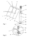
- a lateral, downwardly extending guide element 7, 12 is arranged for the respective curtain edge, which is designed to be curved at its upper end the course of the casting surface 8.
- Each guide element 7, 12 extends over the length of the casting surface 8 and beyond its end parallel to the curtain C, down, see Figure 4, to near the web to be coated 13.
- the guide elements 7, 12 are transversely adjustable on the casting surface 8 attached, while the Querverstellen can either manually or automatically, eg B. via a linear actuator pneumatic, electric or hydraulic, done.
- the guide elements 7, 12 serve to counteract a constriction of the free-falling curtain C at its edges due to the surface tension of the coating material.
- the strip-shaped guide elements 7, 12 have a curtain C facing the inside, which is formed flat.
- the inside of each guide element 7, 12 can be flushed with a surface tension reducing auxiliary liquid, for example with water or the curtain liquid itself.
- the auxiliary liquid flowing down from above on the guide elements 7, 12 causes the curtain C to adhere to the guide elements 7, 12.
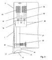
- the auxiliary liquid is supplied via a channel 14 which opens at a short distance above the discharge edge 6 of the casting surface 8 and is connected to a supply line 15, as shown in FIG.
- a suction element 16 is attached, the curtain C facing the inside is aligned with the inside of the guide member 12.
- the suction slot 18 extends perpendicular to the curtain C, its measured length in the web running direction is 0.5 mm to 15 mm, preferably 5 mm to 12 mm, so that the suction function is ensured with appropriate variations of the curtain C. Its height is 0.1 mm to 2 mm, preferably 0.5 mm to 1 mm, and it is arranged on the underside of the suction element 16 so that its distance from the web 13 is 0.5 mm to 3 mm.
- the suction channel is closed at the bottom with a thin, only slightly inclined to the path bottom 19, which ends in the suction slot 18 in a sharp edge.
- the suction of the thickened edge of the coating material thus takes place substantially in a horizontal direction.
- the sharp edge ensures a secure detachment of the coating material, without the so-called "Teapot effect" occurs.
- a suitable rinsing liquid for example with water.
- two flushing lines 20 lead substantially parallel to the suction to the suction slot 18. The rinsing liquid is led away together with the extracted coating material via the suction line 17.
- the impact on the web 13 edge of the curtain C can be set transversely to the web running limited, the two guide elements 12 are made in their lower, the curtain C delimiting part of a limited flexible, elastically bendable material, preferably made of spring steel, as shown in FIG 3 shown.
- the support bar 21 is definitely made of a stiffer material than the guide element and z. B. made of stainless steel and ends at a small distance in front of the suction 16.
- a movable against the guide member 12 adjusting screw 22 is mounted in the lower part of the support bar 21 .
- the adjusting screw 22 makes it possible to adjust the free end of the guide element 12 with the attached suction element 16 limited transversely to the web running direction to adjust the position of the suction slot 18 exactly.
- the course of the guide element 12 can also be limitedly varied with the adjusting screw 22 in order to optimally adjust the guidance and adhesion of the curtain edge.
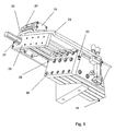
- the guide elements 7, 12 with the elements attached thereto are mounted transversely and steplessly adjustable over the casting surface 8, as shown in FIG.
- the lower guide member 12 is fixed to a cover plate 23.
- the curtain-side edge of the cover plate 23 simultaneously forms the upper guide element 7.
- angle 24 are fixed, which are mounted on one side to a linear unit 25.
- the linear unit 25 in turn is attached to a support plate 26.
- Via a linear guide unit 27, the support plate 26 is manually or automatically displaced.
- the recording of the support plate 26 in the linear guide unit 27 can be seen in FIG.
- FIG. 5 also shows that a further lateral support plate 28 is fastened to the angled lower region of the carrier plate 26.
- the lateral support plate 28 serves to guide and attach guide rods 29, at the ends of inserts are attached.
- the guide rods 29 extend into the distribution chambers 2 and are circumferentially guided in a sealing plate 30 in radial seals.
- the cover plate 23 is moved forward in the web running direction by means of the linear unit 25. This raises the cover plate 23, which rests in the operating state on the casting surface 8, lifted from the casting surface 8. But it is also possible to attach to the front edge of the cover plate 23 a storage, so that the cover plate 23 is pivotally mounted in the web running direction and so can be lifted from the sliding surface.
- the carrier plate 26, 28 is now moved transversely to the curtain C. The method can be done manually, via a simple pulling or pressing on the support plate 26, 28 or via a drive, not shown. During the displacement of the support plate 26, 28 slides the support plate 26, 28 in guides which are connected to the linear guide unit 27.
- the guide rods 29 are moved into the seal plate 30 or out of the seal plate 30.
- the inserts 31 are attached.
- the inserts 31 are guided in the distribution chambers 2 and limit the distribution chambers 2, exactly to the inner edge of the cover plate, which in turn forms the upper guide element 7.
- the insert 31 is preferably made of plastic and provided with threaded inserts 32 in which the guide rods 29 are attached.
- the insert 31 limits the distribution chambers across the curtain and thus limits the width of the outlet slots 9.
- the cover plate 23 is moved back again by means of the linear unit, so that the cover plate 23 rests flush again on the casting surface 8.
- the cover plate 23 serves at its curtain-side edge again as a guide element 7 and at the same time as a seal for the outlet slots 9 above the inserts 31 and outside the coating width for sealing the distribution chambers 2, which are not acted upon by the casting liquid.
- the cavity forming behind the inserts 31 in the distribution chambers 2, ie the area facing away from the curtain C, can optionally be filled with auxiliary liquid.
- the nozzle can be operated with or without auxiliary liquid in the cavity behind the inserts 31. 5
- an angle fitting 33 is introduced into the sealing plate 30 via which the distribution chambers 2 are supplied with the auxiliary liquid, wherein the auxiliary liquid can also be guided via the guide rods 29 to the sliding surface of the insert 31.
- auxiliary liquid By means of the auxiliary liquid is ensured that the adjustment of the width of the outlet slots 9 is possible at any time. It is thus possible to adjust the width of the outlet slots 9 and thus the width of the casting surface 8 continuously and at any time, without the components must be dismantled. It is of course obvious that the described width adjustment is possible on both sides of the nozzle, wherein the two sides of the nozzle are constructed in mirror image.
- the insert 31 is z. B. plastic and preferably has metallic threaded inserts 32. On a thin base plate 34, a wedge-shaped 35 and a cuboid body 36 is formed. The upper part of the base plate 34 extends into the outlet slot 9 and the attached elements 35, 36 run as a sealing body in the distribution chambers 2. In the threaded inserts 32, the guide rods 29 are screwed. The opposite end of the insert 31 limits the distribution chamber 2 to the coating width of the curtain. The insert 31 thus forms a lateral seal between the outlet slot 9 and the distribution chamber 2, which is filled with the casting solution for the curtain C, wherein the auxiliary liquid located behind the insert 31 is intended to prevent sticking of the insert 31.
- the displacement of the inserts 31 takes place in each case by means of two guide rods 29, which are fastened on one side to the side of the insert 31, on the other hand to the lateral support plate 28.
- the lateral support plate 28 is located laterally adjacent to the casting container 1 and is fixedly connected to the support plate 26 so that it can be moved with this transversely to the web running direction by a drive.
- the inserts 31 fixed to the guide rods 29 are positioned so that their inner side is aligned with the inner surface of the guide members 7, so that the width of the distribution chambers 2 coincides exactly with the width of the casting surface 8 and the curtain C. It thus occurs only coating material in width, which corresponds to the desired width of the coating. This ensures that at any set coating width no coating material is lost or must be recirculated.
- the inserts 31 do not stick in the distribution chambers 2 during operation and thus can no longer be moved, they are rinsed from the outside with a rinsing liquid, for example water or a solvent.
- a rinsing liquid for example water or a solvent.
- 30 channels are arranged in the sealing wall, which lead to the individual distribution chambers 2 and are externally connected to a supply with an angle fitting 33 for the rinsing liquid.
- the inserts 31 are arranged with a small clearance in the distribution chambers 2, so that some rinsing liquid can pass through and exits through the outlet slots 9 on the casting surface 8, preferably the rinsing liquid is introduced with an overpressure in the distribution chambers.
- the rinsing liquid can thus also serve as auxiliary liquid for the curtain edges, which improves the adhesion to the guide elements 7.
- the separate supply of auxiliary liquid to the guide elements 7 can thus be spared.
- the rinsing and auxiliary liquid then flows through the casting surface 8 on the inside of the guide elements 7 to the end of the lower guide elements 12 with and ensures a secure adhesion of the curtain edge.
- FIG. 1 shows the structure and the attachment of the guide member 12 on the cover plate 23.
- the guide member 12 is releasably secured by means of a thumbscrew 34 to the cover plate 23. The operator is thus able to release the lower guide element 12 very quickly from the cover plate 23.
- the guide element 12 consists on both sides of two thumbscrews 34, a receptacle 35, a support bar 21 with an adjusting screw 22 and the guide member 12 and attached to the lower end of the guide member 12 suction 16.
- the two thumbscrews 34 sit in recesses 36 and reach with their threads into the recordings, as shown in Figure 2 in section.
- the support bar 21 is rigidly attached.
- the lower guide member 12 is movable in contrast to the support bar 21.
- the guide element 12 can be adjusted transversely to the curtain C, by means of the adjusting screw 22 over a small angular range, designated W in FIG.
Landscapes
- Coating Apparatus (AREA)
- Reverberation, Karaoke And Other Acoustics (AREA)
Claims (8)
- Dispositif pour enduire une bande de matériau en mouvement (13) comprenant un récipient de coulée (1),
qui présente :- une surface de coulée (8) pour distribuer le matériau d'enduction en un rideau tombant librement (C),- au moins une chambre de distribution (2) s'étendant transversalement à la direction d'avance de la bande, comprenant une alimentation (10) pour du matériau de revêtement et une fente de sortie (9) sur la surface de coulée (8) et- deux éléments de guidage latéraux (7, 12) pour les bords du rideau (C), qui s'étendent à chaque fois sur la longueur de la surface de coulée (8) et au-delà de son extrémité parallèlement au rideau (C) vers le bas, et qui sont configurés à leur extrémité supérieure avec une courbure correspondant à l'allure de la surface de coulée (8),caractérisé en ce que les éléments de guidage latéraux (7, 12) de la surface de coulée (8) sont fixés de manière déplaçable transversalement et en ce que l'apport de matériau d'enduction (10) débouche dans la région centrale du récipient de coulée (1) dans la chambre de distribution (2). - Dispositif selon la revendication 1, caractérisé en ce qu'à l'extrémité inférieure de chaque élément de guidage (7, 12) est fixé un élément d'aspiration (16), dont le côté intérieur tourné vers le rideau (C) est en affleurement avec le côté intérieur de l'élément de guidage (7, 12) et à travers lequel passe un canal d'aspiration (17) raccordé à une conduite d'aspiration et qui débouche dans une fente d'aspiration (18).
- Dispositif selon la revendication 1 ou 2, caractérisé par, dans chaque cas, un insert d'étanchéité (31) de chaque côté d'une chambre de distribution (2), dont la section transversale est adaptée à la section transversale de la chambre de distribution (2) et de la fente de sortie (9) et qui peut être déplacé transversalement pour l'ajustement de la largeur efficace de la chambre à la largeur de revêtement.
- Dispositif selon l'une quelconque des revendications 1 à 3, caractérisé en ce que le réglage transversal des éléments de guidage (7, 12) s'effectue de manière accouplée au réglage transversal des inserts (31).
- Dispositif selon l'une quelconque des revendications 1 à 4, caractérisé en ce que le réglage transversal s'effectue automatiquement, notamment par moteur, de préférence au moyen d'un entraînement linéaire.
- Dispositif selon l'une quelconque des revendications 1 à 5, caractérisé en ce que les éléments de guidage (7, 12) sont fixés dans chaque cas à une plaque de support (26, 28) déplaçable en continu et transversalement, qui est connectée fixement à des barres de guidage (29) auxquelles est fixé l'insert (31).
- Dispositif selon l'une quelconque des revendications 1 à 6, caractérisé en ce que la plaque de recouvrement (23) peut être déplacée dans la direction d'avance de la bande par le biais d'une unité linéaire (25), de sorte que la plaque de recouvrement (23) puisse être soulevée de la surface de coulée (8).
- Dispositif selon l'une quelconque des revendications 1 à 7, caractérisé en ce que des éléments de guidage inférieurs (12) peuvent être détachés de la plaque de recouvrement au moyen de vis moletées (34).
Applications Claiming Priority (2)
| Application Number | Priority Date | Filing Date | Title |
|---|---|---|---|
| DE10316999A DE10316999A1 (de) | 2003-04-11 | 2003-04-11 | Vorrichtung zum Beschichten einer laufenden Materialbahn |
| PCT/EP2004/002481 WO2004089555A1 (fr) | 2003-04-11 | 2004-03-11 | Dispositif pour enduire une bande de materiau mobile |
Publications (2)
| Publication Number | Publication Date |
|---|---|
| EP1613439A1 EP1613439A1 (fr) | 2006-01-11 |
| EP1613439B1 true EP1613439B1 (fr) | 2007-05-02 |
Family
ID=33039072
Family Applications (1)
| Application Number | Title | Priority Date | Filing Date |
|---|---|---|---|
| EP04719370A Expired - Lifetime EP1613439B1 (fr) | 2003-04-11 | 2004-03-11 | Dispositif pour enduire une bande de materiau mobile |
Country Status (6)
| Country | Link |
|---|---|
| US (1) | US7556692B2 (fr) |
| EP (1) | EP1613439B1 (fr) |
| CN (1) | CN100398220C (fr) |
| AT (1) | ATE361153T1 (fr) |
| DE (2) | DE10316999A1 (fr) |
| WO (1) | WO2004089555A1 (fr) |
Families Citing this family (14)
| Publication number | Priority date | Publication date | Assignee | Title |
|---|---|---|---|---|
| FI117176B (fi) * | 2005-01-27 | 2006-07-14 | Metso Paper Inc | Laite tasolta syöttävän verhopäällystimen applikointileveyden säätämiseksi |
| DE102005059966B4 (de) * | 2005-12-15 | 2007-10-31 | Polytype Converting S.A. | Vorhangbeschichter mit seitlich verstellbarer Abkantung |
| FI118925B (fi) * | 2006-10-03 | 2008-05-15 | Metso Paper Inc | Menetelmä ja järjestely kuiturainan verhopäällystyksen yhteydessä |
| JP5239008B2 (ja) * | 2007-07-13 | 2013-07-17 | ボイス パテント ゲーエムベーハー | 塗工機の塗工幅調整装置 |
| JP5228226B2 (ja) * | 2007-07-20 | 2013-07-03 | ボイス パテント ゲーエムベーハー | 感熱紙の製造装置 |
| JP2009101321A (ja) * | 2007-10-25 | 2009-05-14 | Voith Patent Gmbh | 塗工幅調整装置 |
| DE102008040403A1 (de) * | 2008-07-15 | 2010-01-21 | Voith Patent Gmbh | Vorhang-Auftragswerk |
| DE102008040406A1 (de) * | 2008-07-15 | 2010-01-21 | Voith Patent Gmbh | Vorhang-Auftragswerk |
| DE102009054737A1 (de) * | 2009-12-16 | 2011-06-22 | Voith Patent GmbH, 89522 | Vorhang-Auftragswerk |
| EP2412446A1 (fr) | 2010-07-30 | 2012-02-01 | Polytype Converting S.A. | Guide de bord pour procédé d'enduction par rideau |
| DE102012004875B3 (de) * | 2012-03-10 | 2012-07-19 | Andritz Küsters Gmbh | Vorrichtung zur Vorhangbeschichtung einer laufenden Warenbahn |
| DE102014102610A1 (de) * | 2014-02-27 | 2015-08-27 | Windmöller & Hölscher Kg | Absaugkanal für eine Absaugvorrichtung zur Förderung von geschnittenen Abfallstreifen einer Folienbahn |
| CN107405924B (zh) * | 2015-04-14 | 2020-05-12 | 惠普深蓝有限责任公司 | 在打印系统中施加流体的装置和方法以及打印系统 |
| CN112657764B (zh) * | 2020-12-18 | 2022-08-09 | 领驰慧润滑科技(河北)有限公司 | 一种可充分浸油且避免油浪费的汽车零配件加工用浸油装置 |
Family Cites Families (16)
| Publication number | Priority date | Publication date | Assignee | Title |
|---|---|---|---|---|
| GB1300746A (en) * | 1969-03-26 | 1972-12-20 | Kodak Ltd | Coating apparatus |
| FR2039983A5 (en) * | 1969-03-26 | 1971-01-15 | Eastman Kodak Co | Photographic coating unit |
| GB1429260A (en) * | 1973-10-12 | 1976-03-24 | Ciba Geigy Ag | Coating apparatus |
| US4135477A (en) | 1975-09-22 | 1979-01-23 | Ciba-Geigy Ag | Curtain coating apparatus |
| GB2165784B (en) * | 1984-10-24 | 1988-01-06 | Nippon Kokan Kk | Nozzle header for producing a flat laminar flow |
| US4659302A (en) * | 1985-01-22 | 1987-04-21 | Jyohoku Seiko Co., Ltd. | Deckle structure for a film extrusion die |
| US4851268A (en) * | 1988-01-29 | 1989-07-25 | Eastman Kodak Company | Curtain coating start-up method and apparatus |
| KR100272064B1 (ko) | 1992-10-27 | 2000-12-01 | 미우라 아끼라 | 다이 도장기 |
| DE4328626A1 (de) * | 1993-08-27 | 1995-03-02 | Motan Verfahrenstechnik | Verfahren zum Betrieb einer Förderleitung mit Dichtstromförderung und Vorrichtung zur Ausübung des Verfahrens |
| DE19513531A1 (de) * | 1995-04-10 | 1996-10-17 | Du Pont Deutschland | Verfahren und Vorrichtung zur Verminderung von Störungen beim Vorhanggießen |
| JPH09253552A (ja) * | 1996-03-21 | 1997-09-30 | Konica Corp | カーテン塗布装置 |
| US6423144B1 (en) * | 1996-08-07 | 2002-07-23 | Matsushita Electric Industrial Co., Ltd. | Coating apparatus and coating method |
| JP3903080B2 (ja) * | 1997-09-26 | 2007-04-11 | 富士フイルム株式会社 | スライドビード塗布方法及び装置、並びに多層塗布方法及び装置 |
| JP2000254567A (ja) * | 1999-03-09 | 2000-09-19 | Mitsubishi Paper Mills Ltd | 塗布方法および塗布装置 |
| DE19962844A1 (de) | 1999-12-23 | 2001-07-05 | Bachofen & Meier Ag Maschf | Verfahren und Vorrichtung zum Beschichten einer laufenden Materialbahn |
| DE10117668A1 (de) | 2001-04-09 | 2002-10-10 | Bachofen & Meier Ag Buelach | Vorrichtung zum Beschichten einer laufenden Materialbahn |
-
2003
- 2003-04-11 DE DE10316999A patent/DE10316999A1/de not_active Withdrawn
-
2004
- 2004-03-11 WO PCT/EP2004/002481 patent/WO2004089555A1/fr active IP Right Grant
- 2004-03-11 DE DE502004003691T patent/DE502004003691D1/de not_active Expired - Lifetime
- 2004-03-11 US US10/552,822 patent/US7556692B2/en not_active Expired - Fee Related
- 2004-03-11 CN CNB2004800057748A patent/CN100398220C/zh not_active Expired - Fee Related
- 2004-03-11 EP EP04719370A patent/EP1613439B1/fr not_active Expired - Lifetime
- 2004-03-11 AT AT04719370T patent/ATE361153T1/de active
Also Published As
| Publication number | Publication date |
|---|---|
| WO2004089555A1 (fr) | 2004-10-21 |
| ATE361153T1 (de) | 2007-05-15 |
| US7556692B2 (en) | 2009-07-07 |
| CN100398220C (zh) | 2008-07-02 |
| CN1756604A (zh) | 2006-04-05 |
| US20060201421A1 (en) | 2006-09-14 |
| EP1613439A1 (fr) | 2006-01-11 |
| DE502004003691D1 (de) | 2007-06-14 |
| DE10316999A1 (de) | 2004-10-28 |
Similar Documents
| Publication | Publication Date | Title |
|---|---|---|
| EP1613439B1 (fr) | Dispositif pour enduire une bande de materiau mobile | |
| DE69936725T2 (de) | Verfahren und vorrichtung zum auftragen von viskosem oder pastösem material auf ein substrat | |
| EP1040227B1 (fr) | Buse fendue pour enduire des bandes de materiau, notamment des bandes de papier ou de carton avec une sauce de couchage au pigment | |
| DE3927680A1 (de) | Auftragsvorrichtung | |
| DE2100771A1 (de) | Gerät zum Auftragen von Fluiden | |
| EP1749586A1 (fr) | Procédé et dispositif de régulation de la largeur et/ou de la densité d'une masse liquide | |
| DE3541784C1 (de) | Vorrichtung zum Auftragen von fluessigem Klebstoff,insbesondere von Schmelzklber(hot melt) | |
| DE2504701C2 (de) | Verfahren und Vorrichtung zum beidseitigen Beschichten einer von unten nach oben bewegten Bahn | |
| DE19651739A1 (de) | Auftragwerk zum direkten oder indirekten Auftragen eines flüssigen oder pastösen Streichmediums auf eine laufende Materialbahn, insbesondere aus Papier oder Karton | |
| DE2359413C3 (de) | Vorrichtung zum Beschichten laufender Werkstoffbahnen aus Papier, Karton, Kunststoff o.dgl. | |
| EP0406529B1 (fr) | Dispositif d'enduction | |
| EP0882839B1 (fr) | Dispositif pour appliquer un matériau liquide ou pâteux sur une bande en mouvement | |
| DE112004001664B4 (de) | Papier- / Kartonbahnstreichvorrichtung | |
| WO2010091986A1 (fr) | Dispositif d'enduction au rideau | |
| EP1239974B1 (fr) | Dispositif de revetement d'une bande de materiau circulante | |
| DE10117668A1 (de) | Vorrichtung zum Beschichten einer laufenden Materialbahn | |
| EP0967327A2 (fr) | Dispositif pour appliquer directement ou indirectement une enduction fluide ou pâteuse sur une bande en mouvement | |
| DE20321262U1 (de) | Vorrichtung zum Beschichten einer laufenden Materialbahn | |
| EP1598115B1 (fr) | Appareil de couchage par rideau | |
| EP2055832A2 (fr) | Dispositif destiné au réglage de la largeur de revêtement d'un revêtement devant être appliqué à l'aide d'une machine de couchage de rideau | |
| EP2014376A2 (fr) | Machine de revêtement par rideau | |
| DE3120716A1 (de) | "verfahren und vorrichtung zum unter-druck-zufuehren eines beschichtungsmaterials auf eine bewegte bahn" | |
| DE8533284U1 (de) | Schlitzdüse | |
| DE2944393C2 (de) | Vorrichtung zum Aufbringen einer dünnen Schicht eines Beschichtungsmaterials auf eine laufende Materialbahn | |
| DE4402626A1 (de) | Vorrichtung zum Streichen einer Papierbahn |
Legal Events
| Date | Code | Title | Description |
|---|---|---|---|
| PUAI | Public reference made under article 153(3) epc to a published international application that has entered the european phase |
Free format text: ORIGINAL CODE: 0009012 |
|
| 17P | Request for examination filed |
Effective date: 20050729 |
|
| AK | Designated contracting states |
Kind code of ref document: A1 Designated state(s): AT BE BG CH CY CZ DE DK EE ES FI FR GB GR HU IE IT LI LU MC NL PL PT RO SE SI SK TR |
|
| AX | Request for extension of the european patent |
Extension state: AL LT LV MK |
|
| DAX | Request for extension of the european patent (deleted) | ||
| RBV | Designated contracting states (corrected) |
Designated state(s): AT CH DE FI LI |
|
| GRAP | Despatch of communication of intention to grant a patent |
Free format text: ORIGINAL CODE: EPIDOSNIGR1 |
|
| GRAS | Grant fee paid |
Free format text: ORIGINAL CODE: EPIDOSNIGR3 |
|
| GRAA | (expected) grant |
Free format text: ORIGINAL CODE: 0009210 |
|
| AK | Designated contracting states |
Kind code of ref document: B1 Designated state(s): AT CH DE FI LI |
|
| REG | Reference to a national code |
Ref country code: CH Ref legal event code: EP Ref country code: CH Ref legal event code: NV Representative=s name: E. BLUM & CO. AG PATENT- UND MARKENANWAELTE VSP |
|
| REF | Corresponds to: |
Ref document number: 502004003691 Country of ref document: DE Date of ref document: 20070614 Kind code of ref document: P |
|
| PLBE | No opposition filed within time limit |
Free format text: ORIGINAL CODE: 0009261 |
|
| STAA | Information on the status of an ep patent application or granted ep patent |
Free format text: STATUS: NO OPPOSITION FILED WITHIN TIME LIMIT |
|
| 26N | No opposition filed |
Effective date: 20080205 |
|
| REG | Reference to a national code |
Ref country code: DE Ref legal event code: R082 Ref document number: 502004003691 Country of ref document: DE Representative=s name: THUL PATENTANWALTSGESELLSCHAFT MBH, DE Effective date: 20120802 Ref country code: DE Ref legal event code: R081 Ref document number: 502004003691 Country of ref document: DE Owner name: ANDRITZ KUESTERS GMBH, DE Free format text: FORMER OWNER: BACHOFEN + MEIER AG MASCHINENFABRIK, BUELACH, CH Effective date: 20120802 |
|
| REG | Reference to a national code |
Ref country code: CH Ref legal event code: PUE Owner name: ANDRITZ KUESTERS GMBH Free format text: BACHOFEN + MEIER AG MASCHINENFABRIK#FELDSTRASSE 80#CH-8180 BUELACH (CH) -TRANSFER TO- ANDRITZ KUESTERS GMBH#EDUARD-KUESTERS-STRASSE 1#47805 KREFELD (DE) |
|
| REG | Reference to a national code |
Ref country code: AT Ref legal event code: PC Ref document number: 361153 Country of ref document: AT Kind code of ref document: T Owner name: ANDRITZ KUESTERS GMBH, DE Effective date: 20121005 |
|
| PGFP | Annual fee paid to national office [announced via postgrant information from national office to epo] |
Ref country code: AT Payment date: 20140324 Year of fee payment: 11 |
|
| PGFP | Annual fee paid to national office [announced via postgrant information from national office to epo] |
Ref country code: CH Payment date: 20140418 Year of fee payment: 11 |
|
| REG | Reference to a national code |
Ref country code: CH Ref legal event code: PL |
|
| REG | Reference to a national code |
Ref country code: AT Ref legal event code: MM01 Ref document number: 361153 Country of ref document: AT Kind code of ref document: T Effective date: 20150311 |
|
| PG25 | Lapsed in a contracting state [announced via postgrant information from national office to epo] |
Ref country code: LI Free format text: LAPSE BECAUSE OF NON-PAYMENT OF DUE FEES Effective date: 20150331 Ref country code: CH Free format text: LAPSE BECAUSE OF NON-PAYMENT OF DUE FEES Effective date: 20150331 |
|
| PG25 | Lapsed in a contracting state [announced via postgrant information from national office to epo] |
Ref country code: AT Free format text: LAPSE BECAUSE OF NON-PAYMENT OF DUE FEES Effective date: 20150311 |
|
| PGFP | Annual fee paid to national office [announced via postgrant information from national office to epo] |
Ref country code: FI Payment date: 20210322 Year of fee payment: 18 |
|
| PGFP | Annual fee paid to national office [announced via postgrant information from national office to epo] |
Ref country code: DE Payment date: 20210319 Year of fee payment: 18 |
|
| REG | Reference to a national code |
Ref country code: DE Ref legal event code: R119 Ref document number: 502004003691 Country of ref document: DE |
|
| REG | Reference to a national code |
Ref country code: FI Ref legal event code: MAE |
|
| PG25 | Lapsed in a contracting state [announced via postgrant information from national office to epo] |
Ref country code: FI Free format text: LAPSE BECAUSE OF NON-PAYMENT OF DUE FEES Effective date: 20220311 |
|
| PG25 | Lapsed in a contracting state [announced via postgrant information from national office to epo] |
Ref country code: DE Free format text: LAPSE BECAUSE OF NON-PAYMENT OF DUE FEES Effective date: 20221001 |