EP1612089A2 - Kraftfahrzeugsitz - Google Patents
Kraftfahrzeugsitz Download PDFInfo
- Publication number
- EP1612089A2 EP1612089A2 EP05013451A EP05013451A EP1612089A2 EP 1612089 A2 EP1612089 A2 EP 1612089A2 EP 05013451 A EP05013451 A EP 05013451A EP 05013451 A EP05013451 A EP 05013451A EP 1612089 A2 EP1612089 A2 EP 1612089A2
- Authority
- EP
- European Patent Office
- Prior art keywords
- upper rail
- bracket
- lock mechanism
- predetermined position
- lock
- Prior art date
- Legal status (The legal status is an assumption and is not a legal conclusion. Google has not performed a legal analysis and makes no representation as to the accuracy of the status listed.)
- Granted
Links
- 230000007246 mechanism Effects 0.000 claims abstract description 83
- 210000000078 claw Anatomy 0.000 description 18
- 238000003825 pressing Methods 0.000 description 12
- 230000000694 effects Effects 0.000 description 1
- 238000004519 manufacturing process Methods 0.000 description 1
- 238000000034 method Methods 0.000 description 1
Images


Classifications
-
- B—PERFORMING OPERATIONS; TRANSPORTING
- B60—VEHICLES IN GENERAL
- B60N—SEATS SPECIALLY ADAPTED FOR VEHICLES; VEHICLE PASSENGER ACCOMMODATION NOT OTHERWISE PROVIDED FOR
- B60N2/00—Seats specially adapted for vehicles; Arrangement or mounting of seats in vehicles
- B60N2/02—Seats specially adapted for vehicles; Arrangement or mounting of seats in vehicles the seat or part thereof being movable, e.g. adjustable
- B60N2/04—Seats specially adapted for vehicles; Arrangement or mounting of seats in vehicles the seat or part thereof being movable, e.g. adjustable the whole seat being movable
- B60N2/06—Seats specially adapted for vehicles; Arrangement or mounting of seats in vehicles the seat or part thereof being movable, e.g. adjustable the whole seat being movable slidable
- B60N2/062—Seats specially adapted for vehicles; Arrangement or mounting of seats in vehicles the seat or part thereof being movable, e.g. adjustable the whole seat being movable slidable transversally slidable
-
- B—PERFORMING OPERATIONS; TRANSPORTING
- B60—VEHICLES IN GENERAL
- B60N—SEATS SPECIALLY ADAPTED FOR VEHICLES; VEHICLE PASSENGER ACCOMMODATION NOT OTHERWISE PROVIDED FOR
- B60N2/00—Seats specially adapted for vehicles; Arrangement or mounting of seats in vehicles
- B60N2/02—Seats specially adapted for vehicles; Arrangement or mounting of seats in vehicles the seat or part thereof being movable, e.g. adjustable
- B60N2/04—Seats specially adapted for vehicles; Arrangement or mounting of seats in vehicles the seat or part thereof being movable, e.g. adjustable the whole seat being movable
- B60N2/06—Seats specially adapted for vehicles; Arrangement or mounting of seats in vehicles the seat or part thereof being movable, e.g. adjustable the whole seat being movable slidable
- B60N2/07—Slide construction
- B60N2/0702—Slide construction characterised by its cross-section
- B60N2/0705—Slide construction characterised by its cross-section omega-shaped
-
- B—PERFORMING OPERATIONS; TRANSPORTING
- B60—VEHICLES IN GENERAL
- B60N—SEATS SPECIALLY ADAPTED FOR VEHICLES; VEHICLE PASSENGER ACCOMMODATION NOT OTHERWISE PROVIDED FOR
- B60N2/00—Seats specially adapted for vehicles; Arrangement or mounting of seats in vehicles
- B60N2/02—Seats specially adapted for vehicles; Arrangement or mounting of seats in vehicles the seat or part thereof being movable, e.g. adjustable
- B60N2/04—Seats specially adapted for vehicles; Arrangement or mounting of seats in vehicles the seat or part thereof being movable, e.g. adjustable the whole seat being movable
- B60N2/06—Seats specially adapted for vehicles; Arrangement or mounting of seats in vehicles the seat or part thereof being movable, e.g. adjustable the whole seat being movable slidable
- B60N2/07—Slide construction
- B60N2/0722—Constructive details
- B60N2/0727—Stop members for limiting sliding movement
-
- B—PERFORMING OPERATIONS; TRANSPORTING
- B60—VEHICLES IN GENERAL
- B60N—SEATS SPECIALLY ADAPTED FOR VEHICLES; VEHICLE PASSENGER ACCOMMODATION NOT OTHERWISE PROVIDED FOR
- B60N2/00—Seats specially adapted for vehicles; Arrangement or mounting of seats in vehicles
- B60N2/02—Seats specially adapted for vehicles; Arrangement or mounting of seats in vehicles the seat or part thereof being movable, e.g. adjustable
- B60N2/04—Seats specially adapted for vehicles; Arrangement or mounting of seats in vehicles the seat or part thereof being movable, e.g. adjustable the whole seat being movable
- B60N2/06—Seats specially adapted for vehicles; Arrangement or mounting of seats in vehicles the seat or part thereof being movable, e.g. adjustable the whole seat being movable slidable
- B60N2/08—Seats specially adapted for vehicles; Arrangement or mounting of seats in vehicles the seat or part thereof being movable, e.g. adjustable the whole seat being movable slidable characterised by the locking device
- B60N2/0812—Location of the latch
- B60N2/0825—Location of the latch outside the rail
-
- B—PERFORMING OPERATIONS; TRANSPORTING
- B60—VEHICLES IN GENERAL
- B60N—SEATS SPECIALLY ADAPTED FOR VEHICLES; VEHICLE PASSENGER ACCOMMODATION NOT OTHERWISE PROVIDED FOR
- B60N2/00—Seats specially adapted for vehicles; Arrangement or mounting of seats in vehicles
- B60N2/02—Seats specially adapted for vehicles; Arrangement or mounting of seats in vehicles the seat or part thereof being movable, e.g. adjustable
- B60N2/04—Seats specially adapted for vehicles; Arrangement or mounting of seats in vehicles the seat or part thereof being movable, e.g. adjustable the whole seat being movable
- B60N2/06—Seats specially adapted for vehicles; Arrangement or mounting of seats in vehicles the seat or part thereof being movable, e.g. adjustable the whole seat being movable slidable
- B60N2/08—Seats specially adapted for vehicles; Arrangement or mounting of seats in vehicles the seat or part thereof being movable, e.g. adjustable the whole seat being movable slidable characterised by the locking device
- B60N2/0831—Movement of the latch
- B60N2/0837—Movement of the latch pivoting
- B60N2/0843—Movement of the latch pivoting about a longitudinal axis
Definitions
- the present invention relates to a seat device for controlling a slide of a vehicle seat.
- a known seat device for a vehicle disclosed in H10-100753A includes a seat cushion, a stepped portion and a stopper unit.
- the seat cushion is attached to a slide rail so as to be slidabe, the stepped portion protrudes toward the slide rail, and the stopper unit moves in an upward/downward direction in conjunction with a rotation of the seat cushion.
- the stopper unit moves downward so as to contact to the stepped portion, and when the seat cushion is rotated so as to be tilt backward, the stopper unit moves upward so as to disengage from the stepped portion.
- the slide rail becomes slidable.
- the stopper unit contacts with an upper surface of the stepped portions so as not to move toward an advancing end, as a result, the rotation of the seat cushion is limited.
- the seat cushion is limited so as not to move to outside the range X
- outside the range X the seat is limited so as not to tilt forward. In this circumstances, the seat cushion cannot be seated outside the range X:
- a range in which the seat body (seat cushion) can slide is changed depending on the rotational position of the seat cushion, however, because the seat body can be slid within the range without any limitation, the seat body may hit, for example an interior equipment, which is positioned within the range.
- the seat body is moved widely in a longitudinal direction, in accordance with this movement, an inertial force is applied to the interior equipment, and when the seat body hits the interior equipment, large impact force is applied to the interior equipment.
- a seat device for a vehicle comprises a lower rail (11) fixed on the vehicle floor (10) so as to extend in a longitudinal direction of the vehicle, an upper rail (12) mounted to the lower rail (11) so as to be slidable and supporting a seat body (15), a first lock mechanism (20) (20) for locking the upper rail (12) at a first position to the lower rail (11), a second lock mechanism (30) for limiting the upper rail (12) at a predetermined position so as not to move further back than the predetermined position, characterized in that the second lock mechanism (30) is locked for limiting the upper rail (12) at the predetermined position so as not to move further back than the predetermined position when the upper rail (12) is unlocked by means of the first lock mechanism (20), and the second lock mechanism (30) is unlocked when the upper rail (12) is locked by means of the first lock mechanism (20).
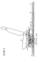
- Fig. 1 illustrates a side view indicating a seat device for a vehicle, which is mounted to a vehicle such as an automobile.
- the seat device for a vehicle includes a pair of lower rails 11 and a pair of upper rails 12.
- the lower rails 11 are extending in a longitudinal direction of the vehicle and fixed on a vehicle floor 10 in a vehicle compartment, and one of the upper rails 12 is slidably attached to one of the lower rails 11, and the other of the upper rails 12 is also slidably attached to the other of the lower rails 11.
- the seat device for a vehicle further includes a supporting plate 13, a pair of slide rails 14 and a seat body 15. Specifically, the supporting plate 13 is supported by the upper rails 12, the slide rails 14 are provided onto the supporting plate 13 so as to extend in a vehicle width direction, and the seat body 15 is slidably supported by the slide rails 14.
- the seat body 15 can slide in a longitudinal direction on the lower rails 11, and also slide in a vehicle width direction on the slide rails 14.
- the seat device for a vehicle further includes a first lock mechanism 20 for fixing the upper rails 12 at a certain position and a second lock mechanism 30 for limiting the upper rails 12 at a predetermined position so as not to move further back than the predetermined position.
- Fig.2 illustrates a cross section of one lower rail 11 and one upper rail 12 along a II-II line in Fig.1.
- a structure of the lower rail 11 will be explained in accordance with Fig.2.
- the lower rail 11 is formed in a U-shape in cross section so as to open on upper portion thereof.
- the lower rail 11 includes two outer side wall portions 11c, two upper surface portions 11a and two inner side wall portions 11b.
- each of the outer side wall portions 11c is extending in a vertical direction, and a top end of each of the outer side wall portions 11c is bent and extending inward so as to form the upper surface portions 11a.
- each of the upper surface portions 11a is bent at an inner portion thereof and extending in a downward direction so as to form the inner side wall portions 11b. Furthermore, as shown in Fig.1, each of the inner side wall portions 11b includes plural lock holes 11d. As described later, the lock holes 11d are used when the upper rails 12 slide on the lower rails 11.
- the upper rail 12 is formed in an inverted U-shape in cross section so as to open on lower portion thereof.
- the upper rail 12 includes two inner side wall portions 12b, two lower surface portions 12c and two outer side wall portions 12a.
- each of the inner side wall portions 12b are extending in a vertical direction, and a lower end of each of the inner side wall portions 12b are bent and extending outward so as to form the lower surface portions 12c.
- each of the lower surface portions 12c is bent at an outer portion thereof and extending in an upper direction so as to form each of the outer side wall portions 12a.
- the upper rail 12 is mounted to the lower rail 11 in a manner where each of the outer side wall portions 12a of the upper rail 12 is positioned between each of the outer side wall portions 11c and each of the inner side wall portions 11b.
- each of the roller members 16 includes a roller 16a, which rolls on an inner surface of each of the upper surface portions 11a of the lower rail 11, and a roller 16b, which rolls on an inner surface of each of the outer side wall portions 11c of the lower rail 11.
- An elastic member 16 being elastically deformed in an inversed U-shape in cross section, is provided between the inner side wall portions 12b of the upper rail 12 in order to apply a force to the each of the inner side wall portions 12b in an outward direction.
- each of the rollers 16b of each of the roller members 16 can firmly contact to each of the outer side wall portions 11c of the lower rail 11, as a result, the upper rail 2 can slides on the lower rail 11 in a manner where each of the rollers 16b rolls on each of the outer side wall portions 11c.
- Fig.3 illustrates a cross section of the seat device for a vehicle along a III-III line in Fig.1.
- the first lock mechanism 20 locks, the upper rail 12 is locked to the lower rail 11 so as not to move in a longitudinal direction of the rails.
- the first lock mechanism 20 includes a bracket 21, which is fixed to the upper rail 12, and a lock lever 23, which is supported by the bracket 21 so as to be rotatable relative to a shaft 22.
- the lock lever 23 includes three lock claws 23, which are inserted in the lock holes 11d of the lower rail 11 as shown in Fig.1, and an actuating piece 23b by which the lock lever 23 is rotated relative to the shaft 22.
- the actuating piece 23b is positioned so as to be pressed down by means of the pressing lever 18, which will be described later.
- the lock lever 23 In a normal state, the lock lever 23 is positioned in a manner where the lock claws 23a thereof is inserted into the lock holes 11d as shown in a solid line in Fig.3.
- the actuating piece 23b When the actuating piece 23b is pressed in a downward direction, the lock lever 23 is rotated relative to the shaft 22 in a clockwise direction so that the lock claws 23a are disengaged from the lock holes 11d (an unlock state).
- the upper rail 12 (seat body 15) becomes slidable on the lower rail 11 in a longitudinal direction thereof.
- the upper rail 12 includes an opening so that the lock lever 23 can be rotated within such opening as shown in a chain double-dashed line in Fig.3.
- the lock holes 11d of the first lock mechanism 20 are formed within an entire length of the lower rail 11 in a longitudinal direction thereof, and the three lock claws 23a of the lock lever 23 are engaged with any three of the lock holes 11d.
- the upper rail 12 is maintained to the lower rail 11 at plural portions, specifically, the upper rail 12 is locked to the lower rail 11 at a first position, which is selected from the plural portions.
- FIG.4(A) illustrates a cross section of a part of the seat device for a vehicle shown in Fig.1 along a IV-IV line
- Fig.4(B) illustrates a flat view of Fig.4(A) seen from the upper side thereof
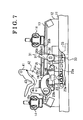
- Fig.5 illustrates a flat view of an interior of the vehicle in the present embodiment
- the Fig.6(A) illustrates a flat view for explaining the first lock mechanism and the second lock mechanism of the embodiment
- Fig.6(B) illustrates a side view of the first and second lock mechanisms shown in Fig.6(A)
- Fig.7 illustrates a side view for explaining an actuation of the seat device for a vehicle
- Fig.8(A) illustrates an enlarged view of the cross section in Fig.4(A) in which a stopper unit 31 is supported by the stopper bracket
- Fig.8(B) illustrates a side view of the vehicle seat mechanism shown in Fig.4(A)
- the second lock mechanism 30 By means of the second lock mechanism 30, the upper rail 12, which becomes slidable in a longitudinal direction of the vehicle after the first lock mechanism 20 is unlocked, can be limited so as not to move further back than predetermined positions (a first predetermined position and a second predetermined position) of the upper rail 12.
- the second lock mechanism 30 includes a stopper unit 31, and the stopper unit 31 is maintained by means of an engaging lever 35 or a stopper bracket 36 so as to be in an upright position (engaged state) in order to limit the upper rail 12 so as not to move further back than a position of a first bracket 32 or a second bracket 33.
- the bracket 32 is attached to a bottom portion of the lower rail 11 at rear of a central portion of the lower rail 11, and the bracket 33 is also attached to a bottom portion of the lower rail 11 at rear of the bracket 32.
- the stopper unit 31 is fixed to the upper rail 12 so as to be rotatable, and a spiral spring 34 is provided at a central point of the rotation of the stopper unit 31 in order to restore and maintain the stopper unit 31, which is rotated by means of the brackets 32 and 33, so as to be in a upright position (a position shown in Fig.4 (A)) at which the spiral spring 34 can be engaged with the brackets 32 and 33.
- a position of the seat body 15 at which the stopper unit 31 engaged with the first bracket 32 is set as a first predetermined position
- a position of the seat boy 15 at which the stopper unit 31 engages with the second bracket 33 is set as a second predetermined position.
- the second lock mechanism 30 limits the upper rail 12 (seat body 15) at the first predetermined position so as not slide in a rearward direction by means of the stopper unit 31, the second bracket 33 and the engaging lever 35.
- a configuration where the seat body 15 is limited at a second predetermined position so as not to move further back than the position of the second bracket 33 will be explained below.
- the engaging lever 35 includes a central point 35a, at which the engaging lever 35 is fixed to the upper rail 12 so as to be rotatable, and a top end portion 35b, which is bent so as to be engaged with the upper end portion of the stopper unit 31.
- the stopper unit 31 is maintained in the upright position (engaged state) in a manner where the upper end portion thereof is engaged with the engaging lever 35.
- a coil spring 37 is provided in order to apply a force to the engaging lever 35 in an anticlockwise direction so as to disengage the top end portion 35b of the engaging lever 35 from the top end portion of the stopper unit 31.
- a connecting portion 35c to which a second connecting member 42 is connected, is provided. By means of the second connecting member 42, the operation force is transmitted from the unlock lever 41 to the engaging lever 35.
- the engaging lever 35 When a force is transmitted from the unlock lever 41 to the engaging lever 35, the engaging lever 35 is rotated in a clockwise direction so as to be engaged at an upper end portion 35b thereof with an top end portion of the stopper unit 31. Specifically, when the unlock lever 41 is operated, the top end portion 35b of the engaging lever 35 is engaged with the upper end portion of the stopper unit 31, so that the stopper unit 31 is maintained so as to be in the upright position.
- the stopper unit 31 maintained in the upright position becomes engaged with the second bracket 33, as a result, the upper rail 12 (seat body 15) is limited so as not to move further back than the position of the second bracket 33.
- the stopper unit 31 is engaged with the second bracket 33.
- the pressing lever 18 is provided on the top of the actuating piece 23b of the lock lever 23. Specifically, the pressing lever 18 is supported by the upper rail 12 so as to be rotatable relative to the central point 18a of the pressing lever 18. As shown in Fig. 6(B), when the pressing lever 18 is rotated in a clockwise direction in Fig. 6(B) relative to the central point 18a, the actuating piece 23b of the lock lever 23 is pressed from the above thereof by means of a top end portion 18b of the pressing lever 18.
- a connecting portion 18c is provided to which a first connecting member 43 is connected.
- the unlock lever 41 when the unlock lever 41 is operated, the pressing lever 18 is rotated so that the actuating piece 23b of the lock lever 23 is pressed from the above thereof, and then the lock lever 23 is unlocked, as a result, the upper rail 12 becomes slidable on the lower rail 11.
- the engaging lever 35 is connected to the unlock lever 41 as mentioned above, the engaging lever 35 is also rotated so that the stopper unit 31 is maintained so as to be in the upright position (engaged state).
- the upper rail 12 is limited at the second predetermined position by means of the second bracket 33 so as not to move further back than the position of the bracket 33.
- the second lock mechanism 30 when the second lock mechanism 30 is unlocked as shown in a chain double-dashed line in Fig.7, the top end portion 35b of the engaging lever 35, the stopper unit 31 and the lock lever 23 become movable. More specifically, the top end portion 35b of the engaging lever 35 is rotated so as to disengage from the upper end portion of the stopper unit 31, and then the stopper unit 31 is rotated, as a result, the upper rail 12 becomes movable in a backward direction. Then, when the upper rail is further moved in a backward direction, because the lock lever 23 is positioned so as to be able to insert into the lock hole 11d, the first lock mechanism 20 becomes capable of being locked.
- the upper rail 12 can be stopped at the second predetermined position, and then, when the second lock mechanism 30 becomes unlocked, the upper rail 12 becomes capable of sliding in a backward direction, as a result, the first lock mechanism 20 becomes capable of being locked.
- the second lock mechanism 30 limits the upper rail 12 (seat body 15) at the first predetermined position so as not slide in a backward direction by means of the stopper unit 31, the first bracket 32, the second bracket 33 and the stopper bracket 36.
- the stopper unit 31 is maintained so as to be in the upright position in a manner where the top end portion of the stopper unit 31 is engaged with the stopper bracket 36.
- the stopper bracket 36 is fixed to the seat body 15, and when the seat body 15 is positioned within a predetermined range in a vehicle width direction, the stopper bracket 36 limits the stopper unit 31 so as not to rotate in a first direction (in a clockwise direction in Fig.8 (B)), as a result the stopper unit 31 is maintained so as to be in the upright position (engaged position).
- the stopper unit 31 is maintained in the upright position at the first predetermined position by means of the stopper bracket 36 so as not to move further backward.
- the stopper unit 31 is not engaged with the stopper bracket 36. In other words, the stopper unit 31 is disengaged from the stopper bracket 36 so that the seat body 15 becomes capable of sliding in a backward direction.
- the seat device for a vehicle comprises a lower rail fixed to a vehicle floor so as to position in a longitudinal direction of a vehicle, an upper rail mounted to the lower rail so as to be slidable, a lock lever rotatably supported by the upper rail, a lock claw formed on the lock lever, lock holes formed on the lower rail continuously in a longitudinal direction thereof, a first lock mechanism by which the lock claw is engaged with at least one of the lock holes in order to lock the upper rail at a first position to the lower rail, a stopper unit rotatably supported by the upper rail, a bracket fixed on the lower rail, an engaging lever rotatably fixed to the upper rail for maintaining the stopper unit in an engaged state, and a second lock mechanism for limiting the upper rail so as not to move further back than a predetermined position by rotating the engaging lever in order to maintain the stopper unit in the engaged state, in which the stopper unit is engaged with the bracket.
- bracket is positioned where the upper rail is limited so as not to move further back than the predetermined position while the lock claw contacts to a side surface of the lower rail.
- the seat device further includes an operating portion to which a first connecting member and a second connecting member are connected, the first connecting member transmitting an operation force for unlocking the lock lever, and the second connecting member transmitting a force for rotating the engaging lever.
- the engaging lever is provided on top of the upper rail so as to be rotatable.
- the seat device for a vehicle comprises a lower rail fixed on the vehicle floor so as to extend in a longitudinal direction of the vehicle, an upper rail mounted to the lower rail so as to be slidable, a slide rail provided on top of the upper rail in a vehicle width direction and supporting the seat body so as to be slidable, a lock lever rotatably supported by the upper rail, a lock claw formed on the lock lever, lock holes formed on the lower rail continuously in a longitudinal direction thereof, a first lock mechanism by which the lock claw is engaged with at least one of the lock holes in order to lock the upper rail at a first position to the lower rail, a stopper unit rotatably supported by the upper rail, a bracket fixed on the lower rail, a stopper bracket for maintaining the stopper unit so as to be in a engaged state when the seat body is in a range of a vehicle width direction, and a second lock mechanism for limiting the upper rail so as not to move further back than a predetermined position by maintaining the stopper unit so as to be in the engaged state,
- stopper bracket is fixed to the seat body. Furthermore, the stopper bracket is positioned in a rotational range of the stopper unit.
- the embodiment may be modified as follow.
- Either one of the engaging lever 35 or the stopper bracket 36 may be provided in order to maintain the stopper unit 31 of the second lock mechanism 30 so as to be in the engaged state.
- the slide rail 14 in the embodiment may not be provided, and only the engaging lever 35 may be provided in order to maintain the stopper unit 31 of the second lock mechanism 30 so as to be in the upright position.
- the force for operating the unlock lever 41 is transmitted to the pressing lever 18 or the engaging lever 35, however, operation portions to which the force is transmitted respectively may be connected to the pressing lever 18 and the engaging lever 35.
- the operation portion may be connected to the first lock mechanism 20 (pressing lever 18), and the operation portion may also be connected to the second lock mechanism 30 (engaging lever 35).
- the movement of the seat body 15 in a rearward direction is temporally stopped at two positions, however, the movement of the seat body 15 may be modified depending on an inner structure of the vehicle.
- the seat body 15 may be stopped at only one position, or may be stopped at three positions.
- the engaging structure such as the roller members provided between the lower rail 11 and the upper rail 12 in the embodiment may be modified.
- the number of the lower rails 11 and the upper rails 12 may be limited to the embodiment, for example, more than three lower rails 11 or the upper rails 11 may be provided to the seat body 15. Even when strength and stability of the vehicle seat is secured, only one lower rail 11 and the upper rail 12 may be provided to the seat body 15.
- the upper rail when the first lock mechanism is unlocked so that the upper rail is slid in a backward direction, the upper rail is limited at the predetermined position by means of the second lock mechanism so as not to move further backward. Further, when the second lock mechanism is unlocked at the predetermined position, the upper rail becomes capable of sliding in a backward direction. Thus, when the upper rail is moved widely in a longitudinal direction, because the upper rail is stopped at the first position, it can be prevented that the seat body hits an interior equipment with a large impact force.
- the stopper unit being maintained at the engaged state is engaged with the bracket so that the upper rail is limited so as not to move further back than the predetermined position.
- stopper unit can be moved in a backward direction from the predetermined position. Specifically, the seat body can be stopped at the predetermined position for a while, and then moved further in a backward direction.
- the bracket is positioned in a manner where the lock claw of the lock lever is contact to the side surface of the lower rail, in other words, the lock claw is not engaged with the lock hole when the stopper unit is engaged with the bracket.
- the first lock mechanism is not locked at the predetermined position.
- the upper rail can be moved in a backward direction by unlocking the second lock mechanism, as a result, operationality can be improved.
- a force for unlocking the first lock mechanism is transmitted to the lock lever by means of the first connecting member
- a force for rotating the engaging lever so as to be engaged with the stopper unit is transmitted by means of the second connecting member.
- the second lock mechanism can be unlocked while the first lock mechanism is incapable of being locked.
- the operating portion is operated in order to slide the upper rail in a backward direction and stop at the predetermined position, and at this position, the operating portion is released in order to further slide the upper rail in a backward direction.
- the upper rail can be slid sequentially only by operating the operating portion, as a result, operationality can be improved.
- the stopper unit maintained in the engaged state is engaged with the bracket, as a result, the upper rail is limited so as not to move further back than the predetermined position.
- the upper rail can be slidable in a backward direction from the predetermined position.
- the seat body can be stopped at the predetermined position, and then the seat body can be further slid in the backward direction.
Applications Claiming Priority (1)
| Application Number | Priority Date | Filing Date | Title |
|---|---|---|---|
| JP2004190398A JP4631327B2 (ja) | 2004-06-28 | 2004-06-28 | 車両用シート装置 |
Publications (3)
| Publication Number | Publication Date |
|---|---|
| EP1612089A2 true EP1612089A2 (de) | 2006-01-04 |
| EP1612089A3 EP1612089A3 (de) | 2009-12-16 |
| EP1612089B1 EP1612089B1 (de) | 2011-10-19 |
Family
ID=35045136
Family Applications (1)
| Application Number | Title | Priority Date | Filing Date |
|---|---|---|---|
| EP05013451A Expired - Fee Related EP1612089B1 (de) | 2004-06-28 | 2005-06-22 | Kraftfahrzeugsitz |
Country Status (4)
| Country | Link |
|---|---|
| US (1) | US7665703B2 (de) |
| EP (1) | EP1612089B1 (de) |
| JP (1) | JP4631327B2 (de) |
| CN (1) | CN1715098B (de) |
Cited By (1)
| Publication number | Priority date | Publication date | Assignee | Title |
|---|---|---|---|---|
| US9108535B2 (en) | 2010-12-20 | 2015-08-18 | Keiper Gmbh & Co. Kg | Longitudinally adjustable vehicle seat |
Families Citing this family (23)
| Publication number | Priority date | Publication date | Assignee | Title |
|---|---|---|---|---|
| GB0616733D0 (en) * | 2006-08-23 | 2006-10-04 | Accuride Int Ltd | A sliding support assembly |
| JP5200438B2 (ja) * | 2007-07-20 | 2013-06-05 | マツダ株式会社 | 車両のシート装置 |
| JP5374073B2 (ja) * | 2008-06-02 | 2013-12-25 | デルタ工業株式会社 | 車両用シート |
| US8245994B2 (en) * | 2009-01-29 | 2012-08-21 | Aisin Seiki Kabushiki Kaisha | Seat apparatus for vehicle |
| WO2011030434A1 (ja) * | 2009-09-10 | 2011-03-17 | トヨタ自動車株式会社 | 車両用シート |
| WO2011041911A1 (en) * | 2009-10-08 | 2011-04-14 | Magna Seating Inc. | Sliding easy entry release mechanism with rest in full rear position |
| WO2012049725A1 (ja) * | 2010-10-12 | 2012-04-19 | テイ・エス テック株式会社 | 乗物用シート |
| JP5594092B2 (ja) | 2010-11-29 | 2014-09-24 | トヨタ紡織株式会社 | 車両用シート |
| DE102011108652B4 (de) * | 2011-07-25 | 2017-10-19 | Adient Luxembourg Holding S.à.r.l. | Fahrzeugsitz, insbesondere Kraftfahrzeugsitz |
| JP5787368B2 (ja) | 2012-02-13 | 2015-09-30 | トヨタ車体株式会社 | シートスライド装置 |
| JP5948946B2 (ja) * | 2012-02-22 | 2016-07-06 | アイシン精機株式会社 | 車両用シートスライド装置 |
| FI125965B (en) | 2012-09-25 | 2016-04-29 | Upm Kymmene Corp | Three-dimensional cell culture |
| JP2016020164A (ja) * | 2014-07-15 | 2016-02-04 | アイシン精機株式会社 | 車両用シートスライド装置 |
| US9937821B2 (en) | 2015-05-22 | 2018-04-10 | AISIN Technical Center of America, Inc. | Center seat stopper control |
| US9849808B2 (en) | 2016-03-08 | 2017-12-26 | Honda Motor Co., Ltd. | End bracket for lateral slide rail for removable seat |
| DE102019206304B4 (de) * | 2018-05-04 | 2022-01-27 | Lear Corporation | Schienenanordnung |
| JP7017490B2 (ja) * | 2018-09-27 | 2022-02-08 | トヨタ自動車株式会社 | 車両用シート構造 |
| CN110575336B (zh) * | 2019-09-29 | 2021-05-28 | 广东博智林机器人有限公司 | 一种锁定定位组件及轮椅床 |
| US11772517B2 (en) | 2020-11-09 | 2023-10-03 | Ford Global Technologies, Llc | Vehicular system capable of adjusting a passenger compartment from a child seat arrangement to a second arrangement |
| US11772520B2 (en) | 2020-11-09 | 2023-10-03 | Ford Global Technologies, Llc | Remote notification and adjustment of a passenger compartment arrangement |
| US11904732B2 (en) | 2020-11-09 | 2024-02-20 | Ford Global Technologies, Llc | Vehicular system capable of adjusting a passenger compartment from a first arrangement to a child care arrangement |
| US11731535B2 (en) | 2020-11-09 | 2023-08-22 | Ford Global Technologies, Llc | Vehicular system capable of adjusting a passenger compartment from a child care arrangement to a second arrangement |
| US11772519B2 (en) | 2020-11-09 | 2023-10-03 | Ford Global Technologies, Llc | Vehicular system capable of adjusting a passenger compartment from a first arrangement to a child seat arrangement |
Citations (3)
| Publication number | Priority date | Publication date | Assignee | Title |
|---|---|---|---|---|
| JPH10100753A (ja) * | 1996-09-30 | 1998-04-21 | Toyota Auto Body Co Ltd | スライドシート |
| JPH10203210A (ja) * | 1997-01-28 | 1998-08-04 | Takashimaya Nippatsu Kogyo Kk | 自動車用シート |
| DE10231097A1 (de) * | 2002-07-10 | 2004-01-22 | Bayerische Motoren Werke Ag | Fahrzeugsitz |
Family Cites Families (42)
| Publication number | Priority date | Publication date | Assignee | Title |
|---|---|---|---|---|
| JPS6224609Y2 (de) * | 1980-08-14 | 1987-06-23 | ||
| BE899282A (fr) * | 1984-03-29 | 1984-07-16 | Ieteren N V Sa D | Dispositif pour modifier la position laterale d'un siege de vehicule. |
| JPH065255Y2 (ja) * | 1988-06-30 | 1994-02-09 | 株式会社タチエス | ウォークイン装置付自動車用シート |
| US4964608A (en) * | 1989-02-09 | 1990-10-23 | Hoover Universal, Inc. | Vehicle seat adjuster with integral positive locking traveling seat belt anchorage |
| FR2682332B1 (fr) * | 1991-10-11 | 1993-12-17 | Faure Automobile Bertrand | Glissiere pour siege de vehicule a position de retour fixe. |
| JPH0618058U (ja) * | 1992-08-21 | 1994-03-08 | シロキ工業株式会社 | シートトラック装置 |
| FR2695885B1 (fr) * | 1992-09-22 | 1994-12-02 | Faure Bertrand Automobile | Glissière de positionnement d'un siège à mémoire interne coopérant avec le profilé fixe de la glissière. |
| JP3142204B2 (ja) | 1994-05-11 | 2001-03-07 | 難波プレス工業株式会社 | 車両用シート |
| FR2722149B1 (fr) * | 1994-07-08 | 1996-09-20 | Faure Bertrand Equipements Sa | Glissiere pour siege de vehicule, et siege de vehicule equipe d'une telle glissiere |
| JPH08282346A (ja) * | 1995-04-13 | 1996-10-29 | Delta Kogyo Co Ltd | 車両用シートスライダのストッパ機構 |
| CA2215220C (en) * | 1996-09-26 | 2001-01-30 | Hatuo Hayakawa | Automotive seat slide device |
| US5800015A (en) * | 1996-10-16 | 1998-09-01 | Tachi-S Co., Ltd. | Long slide rail device for vehicle seat |
| JPH10194020A (ja) * | 1997-01-16 | 1998-07-28 | Ikeda Bussan Co Ltd | 自動車リヤシートのスライド装置 |
| JP3269433B2 (ja) * | 1997-04-03 | 2002-03-25 | トヨタ車体株式会社 | 車両用回転座席 |
| US6102478A (en) * | 1998-01-16 | 2000-08-15 | Lear Corporation | Vehicle seat slide mechanism |
| FR2778613B1 (fr) * | 1998-05-12 | 2000-07-21 | Faure Bertrand Equipements Sa | Glissiere pour siege de vehicule a memoire de reglage longitudinale et siege comportant une telle glissiere |
| US6059345A (en) * | 1998-06-18 | 2000-05-09 | Tachi-S Co., Ltd. | Slide rail device for vehicle seat |
| JP2000085421A (ja) * | 1998-09-16 | 2000-03-28 | Toyo Seat Co Ltd | 車両用シートのスライド装置 |
| JP4106137B2 (ja) * | 1998-11-13 | 2008-06-25 | アイシン精機株式会社 | 車両用シートスライド装置 |
| JP4120078B2 (ja) * | 1998-12-25 | 2008-07-16 | アイシン精機株式会社 | 車両シートのウォークイン装置 |
| JP3560846B2 (ja) * | 1999-05-11 | 2004-09-02 | 富士機工株式会社 | シートスライド装置 |
| JP2003527990A (ja) * | 1999-09-22 | 2003-09-24 | マグナ シーティング システムズ インコーポレイテッド | 乗込みの容易なシート軌道組立体 |
| JP4465835B2 (ja) * | 2000-08-28 | 2010-05-26 | アイシン精機株式会社 | 車両用シート装置 |
| DE10050959B4 (de) * | 2000-10-13 | 2005-11-24 | Keiper Gmbh & Co.Kg | Sitzlängsverstellung |
| JP3635639B2 (ja) | 2001-10-16 | 2005-04-06 | 本田技研工業株式会社 | 車両用シート |
| KR100442746B1 (ko) * | 2001-11-08 | 2004-08-02 | 주식회사다스 | 자동차용 시트레일의 로킹시스템 |
| JP3678191B2 (ja) * | 2001-11-12 | 2005-08-03 | アイシン精機株式会社 | シートスライド装置 |
| JP4249931B2 (ja) * | 2002-02-28 | 2009-04-08 | アイシン精機株式会社 | 車両用シートスライド装置 |
| JP3906740B2 (ja) * | 2002-05-14 | 2007-04-18 | マツダ株式会社 | 車両のシート装置 |
| JP4080268B2 (ja) * | 2002-07-19 | 2008-04-23 | 富士機工株式会社 | シートスライド装置のロック部構造及びその組付方法 |
| JP4103524B2 (ja) * | 2002-09-30 | 2008-06-18 | アイシン精機株式会社 | 車両シートのウォークイン装置 |
| JP4104969B2 (ja) * | 2002-12-19 | 2008-06-18 | 富士機工株式会社 | 車両のシートスライド装置 |
| US6869057B2 (en) * | 2002-12-20 | 2005-03-22 | Fuji Kiko Co., Ltd. | Seat slide device |
| US7243995B2 (en) * | 2003-06-20 | 2007-07-17 | Mazda Motor Corporation | Seat structure for vehicle |
| JP2005145232A (ja) * | 2003-11-14 | 2005-06-09 | Aisin Seiki Co Ltd | シートスライド装置 |
| CN1660625B (zh) * | 2004-02-24 | 2010-05-05 | 爱信精机株式会社 | 用于车辆的座椅滑动装置 |
| JP4649864B2 (ja) * | 2004-04-15 | 2011-03-16 | マツダ株式会社 | 車両用シート装置システム |
| KR100590963B1 (ko) * | 2004-05-07 | 2006-06-19 | 기아자동차주식회사 | 차량용 탈착식 시트를 위한 롱 슬라이드형 레일 |
| JP4433925B2 (ja) * | 2004-07-27 | 2010-03-17 | アイシン精機株式会社 | シートスライド装置 |
| JP4479482B2 (ja) * | 2004-11-24 | 2010-06-09 | アイシン精機株式会社 | 車両用シート装置 |
| US7328877B2 (en) * | 2004-12-20 | 2008-02-12 | Aisin Seiki Kabushiki Kaisha | Seat slide apparatus for a vehicle |
| JP4363531B2 (ja) * | 2006-01-13 | 2009-11-11 | トヨタ紡織株式会社 | 車両のスライドレール構造 |
-
2004
- 2004-06-28 JP JP2004190398A patent/JP4631327B2/ja not_active Expired - Fee Related
-
2005
- 2005-06-22 EP EP05013451A patent/EP1612089B1/de not_active Expired - Fee Related
- 2005-06-24 US US11/165,334 patent/US7665703B2/en not_active Expired - Fee Related
- 2005-06-28 CN CN200510080226.8A patent/CN1715098B/zh not_active Expired - Fee Related
Patent Citations (3)
| Publication number | Priority date | Publication date | Assignee | Title |
|---|---|---|---|---|
| JPH10100753A (ja) * | 1996-09-30 | 1998-04-21 | Toyota Auto Body Co Ltd | スライドシート |
| JPH10203210A (ja) * | 1997-01-28 | 1998-08-04 | Takashimaya Nippatsu Kogyo Kk | 自動車用シート |
| DE10231097A1 (de) * | 2002-07-10 | 2004-01-22 | Bayerische Motoren Werke Ag | Fahrzeugsitz |
Cited By (1)
| Publication number | Priority date | Publication date | Assignee | Title |
|---|---|---|---|---|
| US9108535B2 (en) | 2010-12-20 | 2015-08-18 | Keiper Gmbh & Co. Kg | Longitudinally adjustable vehicle seat |
Also Published As
| Publication number | Publication date |
|---|---|
| CN1715098B (zh) | 2010-05-05 |
| EP1612089B1 (de) | 2011-10-19 |
| EP1612089A3 (de) | 2009-12-16 |
| JP2006008028A (ja) | 2006-01-12 |
| US7665703B2 (en) | 2010-02-23 |
| CN1715098A (zh) | 2006-01-04 |
| US20050285007A1 (en) | 2005-12-29 |
| JP4631327B2 (ja) | 2011-02-16 |
Similar Documents
| Publication | Publication Date | Title |
|---|---|---|
| EP1612089B1 (de) | Kraftfahrzeugsitz | |
| EP1705054B1 (de) | Fahrzeugsitz | |
| JP4863051B2 (ja) | 車両用ウォークイン装置 | |
| EP1621391B1 (de) | Sitzgleitschiene | |
| CA2534770C (en) | Locking mechanism for seat track assembly | |
| JPH065255Y2 (ja) | ウォークイン装置付自動車用シート | |
| US8740265B2 (en) | Dual pawl latch mechanism for a dual door assembly | |
| CA2577618A1 (en) | Easy entry seat track release mechanism | |
| JP2009241919A (ja) | シートスライド装置 | |
| EP2748027B1 (de) | Positiv eingerastete verriegelung für sitzeinstellungsanordnung | |
| EP1780070B1 (de) | Sitzvorrichtung für ein Fahrzeug | |
| JP2003252086A (ja) | シートスライド装置 | |
| WO2009145045A1 (ja) | シートスライド装置 | |
| EP1950100A2 (de) | Pedaleinheit für ein Kraftfahrzeug | |
| KR101755828B1 (ko) | 도어 열림 방지를 위한 도어 래치 링크구조 | |
| JP3942084B2 (ja) | 車両用シート | |
| WO2009139348A1 (ja) | シートスライド装置 | |
| GB2410057A (en) | Inertia controlled seat track locking mechanism | |
| JP3755428B2 (ja) | 車両用シートのスライド装置 | |
| JPH0228979Y2 (de) | ||
| JP5278780B2 (ja) | 車両用ウォークイン装置 | |
| EP4037932B1 (de) | Sitzanordnung mit rücklaufsperrelement | |
| KR100507306B1 (ko) | 자동차의 시트용 롱 슬라이드 록킹구조 | |
| JP2788644B2 (ja) | シートスライド装置 | |
| JPH03277301A (ja) | バックル装置 |
Legal Events
| Date | Code | Title | Description |
|---|---|---|---|
| PUAI | Public reference made under article 153(3) epc to a published international application that has entered the european phase |
Free format text: ORIGINAL CODE: 0009012 |
|
| AK | Designated contracting states |
Kind code of ref document: A2 Designated state(s): AT BE BG CH CY CZ DE DK EE ES FI FR GB GR HU IE IS IT LI LT LU MC NL PL PT RO SE SI SK TR |
|
| AX | Request for extension of the european patent |
Extension state: AL BA HR LV MK YU |
|
| PUAL | Search report despatched |
Free format text: ORIGINAL CODE: 0009013 |
|
| AK | Designated contracting states |
Kind code of ref document: A3 Designated state(s): AT BE BG CH CY CZ DE DK EE ES FI FR GB GR HU IE IS IT LI LT LU MC NL PL PT RO SE SI SK TR |
|
| AX | Request for extension of the european patent |
Extension state: AL BA HR LV MK YU |
|
| 17P | Request for examination filed |
Effective date: 20091214 |
|
| AKX | Designation fees paid |
Designated state(s): DE FR |
|
| RIC1 | Information provided on ipc code assigned before grant |
Ipc: B60N 2/08 20060101ALI20110321BHEP Ipc: B60N 2/07 20060101AFI20110321BHEP |
|
| GRAP | Despatch of communication of intention to grant a patent |
Free format text: ORIGINAL CODE: EPIDOSNIGR1 |
|
| GRAS | Grant fee paid |
Free format text: ORIGINAL CODE: EPIDOSNIGR3 |
|
| GRAA | (expected) grant |
Free format text: ORIGINAL CODE: 0009210 |
|
| RIN1 | Information on inventor provided before grant (corrected) |
Inventor name: TANAKA, TOSHIYUKI,C/O INTELLECTUAL PROPERTY DEPT., |
|
| AK | Designated contracting states |
Kind code of ref document: B1 Designated state(s): DE FR |
|
| REG | Reference to a national code |
Ref country code: DE Ref legal event code: R096 Ref document number: 602005030659 Country of ref document: DE Effective date: 20111215 |
|
| PLBE | No opposition filed within time limit |
Free format text: ORIGINAL CODE: 0009261 |
|
| STAA | Information on the status of an ep patent application or granted ep patent |
Free format text: STATUS: NO OPPOSITION FILED WITHIN TIME LIMIT |
|
| 26N | No opposition filed |
Effective date: 20120720 |
|
| REG | Reference to a national code |
Ref country code: DE Ref legal event code: R097 Ref document number: 602005030659 Country of ref document: DE Effective date: 20120720 |
|
| PGFP | Annual fee paid to national office [announced via postgrant information from national office to epo] |
Ref country code: DE Payment date: 20140618 Year of fee payment: 10 |
|
| PGFP | Annual fee paid to national office [announced via postgrant information from national office to epo] |
Ref country code: FR Payment date: 20140609 Year of fee payment: 10 |
|
| REG | Reference to a national code |
Ref country code: DE Ref legal event code: R119 Ref document number: 602005030659 Country of ref document: DE |
|
| REG | Reference to a national code |
Ref country code: FR Ref legal event code: ST Effective date: 20160229 |
|
| PG25 | Lapsed in a contracting state [announced via postgrant information from national office to epo] |
Ref country code: DE Free format text: LAPSE BECAUSE OF NON-PAYMENT OF DUE FEES Effective date: 20160101 |
|
| PG25 | Lapsed in a contracting state [announced via postgrant information from national office to epo] |
Ref country code: FR Free format text: LAPSE BECAUSE OF NON-PAYMENT OF DUE FEES Effective date: 20150630 |