EP1607357B1 - Folding machine and process for producing article being fixed - Google Patents
Folding machine and process for producing article being fixed Download PDFInfo
- Publication number
- EP1607357B1 EP1607357B1 EP04722079A EP04722079A EP1607357B1 EP 1607357 B1 EP1607357 B1 EP 1607357B1 EP 04722079 A EP04722079 A EP 04722079A EP 04722079 A EP04722079 A EP 04722079A EP 1607357 B1 EP1607357 B1 EP 1607357B1
- Authority
- EP
- European Patent Office
- Prior art keywords
- web
- section
- roller
- folded
- folding
- Prior art date
- Legal status (The legal status is an assumption and is not a legal conclusion. Google has not performed a legal analysis and makes no representation as to the accuracy of the status listed.)
- Expired - Lifetime
Links
- 238000000034 method Methods 0.000 title claims description 11
- 230000008569 process Effects 0.000 title description 6
- 230000008859 change Effects 0.000 claims abstract description 6
- 230000002745 absorbent Effects 0.000 claims description 13
- 239000002250 absorbent Substances 0.000 claims description 13
- 229910052770 Uranium Inorganic materials 0.000 claims description 11
- 229910052720 vanadium Inorganic materials 0.000 claims description 11
- 238000004519 manufacturing process Methods 0.000 claims description 8
- 238000011144 upstream manufacturing Methods 0.000 claims description 7
- 238000005520 cutting process Methods 0.000 claims description 4
- 230000009471 action Effects 0.000 claims description 3
- OKTJSMMVPCPJKN-UHFFFAOYSA-N Carbon Chemical compound [C] OKTJSMMVPCPJKN-UHFFFAOYSA-N 0.000 description 6
- 238000001514 detection method Methods 0.000 description 6
- 230000008602 contraction Effects 0.000 description 4
- 238000006073 displacement reaction Methods 0.000 description 4
- 229910052799 carbon Inorganic materials 0.000 description 3
- 229910002804 graphite Inorganic materials 0.000 description 3
- 239000010439 graphite Substances 0.000 description 3
- 239000000463 material Substances 0.000 description 3
- 229910052751 metal Inorganic materials 0.000 description 3
- 239000002184 metal Substances 0.000 description 3
- GDOPTJXRTPNYNR-UHFFFAOYSA-N CC1CCCC1 Chemical compound CC1CCCC1 GDOPTJXRTPNYNR-UHFFFAOYSA-N 0.000 description 2
- XEEYBQQBJWHFJM-UHFFFAOYSA-N Iron Chemical compound [Fe] XEEYBQQBJWHFJM-UHFFFAOYSA-N 0.000 description 2
- 230000005856 abnormality Effects 0.000 description 2
- 230000007246 mechanism Effects 0.000 description 2
- 230000003287 optical effect Effects 0.000 description 2
- 230000004044 response Effects 0.000 description 2
- 238000007789 sealing Methods 0.000 description 2
- 230000003746 surface roughness Effects 0.000 description 2
- 241001123248 Arma Species 0.000 description 1
- 230000004075 alteration Effects 0.000 description 1
- 229910052782 aluminium Inorganic materials 0.000 description 1
- XAGFODPZIPBFFR-UHFFFAOYSA-N aluminium Chemical compound [Al] XAGFODPZIPBFFR-UHFFFAOYSA-N 0.000 description 1
- 238000013528 artificial neural network Methods 0.000 description 1
- 230000008901 benefit Effects 0.000 description 1
- 238000012790 confirmation Methods 0.000 description 1
- 239000007799 cork Substances 0.000 description 1
- -1 e.g. Substances 0.000 description 1
- 238000005530 etching Methods 0.000 description 1
- 229910052742 iron Inorganic materials 0.000 description 1
- 238000010422 painting Methods 0.000 description 1
- 238000005192 partition Methods 0.000 description 1
- 238000003825 pressing Methods 0.000 description 1
- 230000009467 reduction Effects 0.000 description 1
- 239000011265 semifinished product Substances 0.000 description 1
- 230000000087 stabilizing effect Effects 0.000 description 1
- 229910052721 tungsten Inorganic materials 0.000 description 1
- 238000004804 winding Methods 0.000 description 1
Images


Classifications
-
- B—PERFORMING OPERATIONS; TRANSPORTING
- B65—CONVEYING; PACKING; STORING; HANDLING THIN OR FILAMENTARY MATERIAL
- B65H—HANDLING THIN OR FILAMENTARY MATERIAL, e.g. SHEETS, WEBS, CABLES
- B65H23/00—Registering, tensioning, smoothing or guiding webs
- B65H23/02—Registering, tensioning, smoothing or guiding webs transversely
- B65H23/0204—Sensing transverse register of web
-
- A—HUMAN NECESSITIES
- A61—MEDICAL OR VETERINARY SCIENCE; HYGIENE
- A61F—FILTERS IMPLANTABLE INTO BLOOD VESSELS; PROSTHESES; DEVICES PROVIDING PATENCY TO, OR PREVENTING COLLAPSING OF, TUBULAR STRUCTURES OF THE BODY, e.g. STENTS; ORTHOPAEDIC, NURSING OR CONTRACEPTIVE DEVICES; FOMENTATION; TREATMENT OR PROTECTION OF EYES OR EARS; BANDAGES, DRESSINGS OR ABSORBENT PADS; FIRST-AID KITS
- A61F13/00—Bandages or dressings; Absorbent pads
- A61F13/15—Absorbent pads, e.g. sanitary towels, swabs or tampons for external or internal application to the body; Supporting or fastening means therefor; Tampon applicators
- A61F13/15577—Apparatus or processes for manufacturing
- A61F13/15707—Mechanical treatment, e.g. notching, twisting, compressing, shaping
- A61F13/15747—Folding; Pleating; Coiling; Stacking; Packaging
-
- B—PERFORMING OPERATIONS; TRANSPORTING
- B65—CONVEYING; PACKING; STORING; HANDLING THIN OR FILAMENTARY MATERIAL
- B65H—HANDLING THIN OR FILAMENTARY MATERIAL, e.g. SHEETS, WEBS, CABLES
- B65H23/00—Registering, tensioning, smoothing or guiding webs
- B65H23/02—Registering, tensioning, smoothing or guiding webs transversely
- B65H23/032—Controlling transverse register of web
- B65H23/038—Controlling transverse register of web by rollers
-
- B—PERFORMING OPERATIONS; TRANSPORTING
- B65—CONVEYING; PACKING; STORING; HANDLING THIN OR FILAMENTARY MATERIAL
- B65H—HANDLING THIN OR FILAMENTARY MATERIAL, e.g. SHEETS, WEBS, CABLES
- B65H45/00—Folding thin material
- B65H45/02—Folding limp material without application of pressure to define or form crease lines
- B65H45/06—Folding webs
- B65H45/08—Folding webs longitudinally
- B65H45/09—Doubling, i.e. folding into half of width
-
- B—PERFORMING OPERATIONS; TRANSPORTING
- B65—CONVEYING; PACKING; STORING; HANDLING THIN OR FILAMENTARY MATERIAL
- B65H—HANDLING THIN OR FILAMENTARY MATERIAL, e.g. SHEETS, WEBS, CABLES
- B65H45/00—Folding thin material
- B65H45/12—Folding articles or webs with application of pressure to define or form crease lines
- B65H45/22—Longitudinal folders, i.e. for folding moving sheet material parallel to the direction of movement
Definitions
- the present invention relates to a web folding apparatus and a method for producing a worn article.
- a semi-finished product thereof e.g., a web
- a web is sometimes folded in two (for example, United States Patent No. 3,828,367 ).
- a web is folded in two, it is ideally folded with the edges on both sides being aligned with each other.
- it is typically difficult to fold a web in such a manner.
- a web guider slightly turns the orientation of a pair of guide rollers about a vertical line V, thereby changing the angle of the guide rollers with respect to the running direction of the web, and adjusts the tension on each side edge of the web (the tension along the web running direction) so that the web moves along a predetermined path (see e.g. page 3, paragraph [0045]).
- the web guider is positioned in a region wherein the web is drastically bended, so the web guider can not be positioned between the abutting member and the nipping member. It follows that the web guider positioned before the folding step makes the response of controlling the running direction of the web slow.
- An object of present invention is to provide a folding apparatus and a method for producing a worn article in which the tension of the web is not drastically changed, yet improving the speed in response for controlling the web, while the opposite side portion (side edge) of the web can be brought into a predetermined positional relationship when folding the web in two.
- a folding apparatus comprising: an abutting member provided so as to extend in a running direction between opposites side edges of a continuous web, wherein the abutting member abuts against the web to fold the web into a V or U shape; a nipping member provided downstream of the abutting member for nipping the web folded by the abutting member so as to fold the web in two; a contact section provided between an upstream end of the abutting member and the nipping member for contacting an inner surface and/or an outer surface of the web being folded in the V or U shape; and a detecting section for detecting a reference portion of the web to be used as a reference in a web folding operation so as to output a positional information regarding a position of the detected reference portion, wherein the folding apparatus controls an action of the contact section based on the positional information so as to bring a positional relationship between the opposite side of edges of the web closer to a predetermined positional relationship, whereby the contact section comprises at least one roller
- the folding apparatus characterized in that the contact section comprises a first roller and a second roller, the first roller and the second roller contact a first and a second side surface of the web, standing face to face each other, folded in the V or U shape by the abutting member.
- the reference portion of the web is detected, and the running direction of the web is corrected so as to reduce the diversion of the path of the web.
- the tension acting upon the opposite side edge portions of the web is adjusted by changing the state of contact of the contact section.
- the path of the web is adjusted, and the positional relationship between the opposite side edges of the web is brought closer to a predetermined positional relationship. Therefore, it is possible to fold the web into a predetermined state.
- the web guider directly corrects the moving direction of the web by exerting an external force on the web in the folding section, i.e., exerting an external force on a portion of the web that has started to be folded. Therefore, even if the web runs at a high speed, it is possible to fold the web in two so that the opposite side edges of the web are in a predetermined positional relationship with respect to each other.
- the method for "changing the state of contact” may be changing the inclination angle of the contact section contacting the web with respect to the running direction of the web, or changing the rotation speed or the rotation resistance of the rollers contacting the web.
- the detecting section typically, the detecting section generates the positional information by using each of the opposite side edges of the web as a "reference portion".
- a reference portion In a case where a graphical pattern or a picture is printed on the web, such a graphical pattern or a picture may alternatively be used as the reference portion, in which case the detecting section generates the positional information of the web by detecting the reference portion and performing an image processing operation.
- the detecting section for detecting the reference portion may be an ultrasonic sensor, an optical sensor (e.g., an infrared sensor), an air sensor, etc.
- the deviation of the web may be detected by processing an image obtained by using a CCD camera or a linear sensor (line sensor).
- the type of a sensor is appropriately selected depending on the type of the web. For example, in a case where the air can be easily passed through the web, it is preferred to use an ultrasonic sensor or an optical sensor. In a case where the web is transparent or semitransparent, it is preferred to use an ultrasonic sensor or an air sensor.
- the detection of the opposite side edges, as the reference portions, is preferably performed before the web is completely folded in two. It is generally preferred that the detection is performed when the web not folded at all is starting to be folded, or immediately before the web is completely folded in two. More specifically, it is preferred that the detection is performed upstream and/or downstream of the abutting member for folding the web in two in the folding section.
- the position at which the detection of the present invention is performed is not limited to any particular position. Alternatively, even after the web is folded, a deviation (misalignment) between the edges of the folded web may be detected by using a detector having a high precision.
- the "folding section” refers to a section responsible for the process of folding the web so that the opposite side edges of the web are in a predetermined positional relationship with respect to each other, starting from a state where the web is not folded at all.
- a sensor for detecting at least the side edges is located in the "folding section”.
- the web is typically folded in two so that the positions of the opposite side edges are aligned with each other.
- the web is folded in two while correcting the path of the web so as to "bring the relationship between the opposite side edges closer to a predetermined relationship (a relative positional relationship)".
- the web may be folded in two so that one of the opposite side edges of the web is protruding past the other side edge by a predetermined amount.
- opposite side edges of a web refers to a pair of side edges thereof that are parallel to the running direction of the web.
- the path of the web can be corrected by adjusting the tension acting upon the opposite side edge portions of the web while the web is being carried.
- the abutting member may be controlled based on the positional information to be moved in the width direction and in the vertical direction.
- the present invention does not limit the structure of the mechanism or apparatus for correcting the relative position of the web with respect to the abutting member.
- a method for producing a worn article of the present invention includes the steps of: placing an absorbent body on a surface along the running direction of a continuous web; folding the web in two in a folding section so that opposite side edges of the web are close to or aligned with each other; detecting a reference portion of the web to be used as a reference in a folding operation to generate positional information regarding a position of the detected reference portion; correcting a path of the web based on the positional information so that the opposite side edges of the folded web are in a predetermined positional relationship with respect to each other by a contact section contacting with the web in the folding section; bonding portions of the folded web to each other to form a bonded portion; and cutting the bonded web along the bonded portion.
- the contact section uses at least one roller extending in a direction of an axis along a width direction of the web folded by an abutting member.
- a driving section is driven to change an orientation of the at least one roller with the web so as to change an inclination angle of the axis of the at least one roller with respect to the running direction of the web while the at least one roller contacts the web folded in the V or U shape, each of the opposite side edges of the web (W) being spaced apart from each other, thereby correcting a path of the web based on the positional information so that the opposite side edges of the folded web are in the predetermined positional relationship with respect to each other by changing an external force transmitted from the at least one roller to the web.
- worn article includes a sanitary napkin, and the like, as well as a disposable diaper and disposable pants.
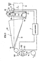
- FIG. 1 is a schematic perspective view showing a production apparatus for producing a disposable worn article according to an embodiment of the present invention.
- FIG. 2 is a schematic side view showing an attachment section.
- FIG. 3 is a schematic side view showing a folding section.
- FIGs. 4(a), 4(b), 4(c) and 4(d) are transverse sectional views each showing a contact section.
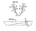
- FIGs. 5(a) and 5(b) are a transverse sectional view and a perspective view, respectively, showing another example of a contact section.
- a production apparatus shown in FIG. 1 includes a placement section 10 , an attachment section 20 , a hole-forming section 30 , a folding section 40 , a twisting section 50 , and a bonding/cutting section 60 .
- this apparatus continuously carries a web W while performing various processes in the sections 10 , 20 , ..., 60 .
- absorbent bodies C are placed at regular intervals on the web W .
- the absorbent body C may be placed directly onto the web W by a drum 11 , or the like, or the absorbent body C may be first placed on another web, which is then placed over the web W .
- a waist elastic member F is introduced onto the web W on which the absorbent bodies C are placed.
- a waist elastic member F2 may be introduced between the web W and the other web 12 denoted by a broken line.
- the leg elastic member L and the waist elastic member F2 may be simultaneously attached onto the web W.
- the waist elastic member F2 and the leg elastic member L are fixed between the web W and the other web 12 while being passed between nip rollers 70 and 71.
- the leg elastic member L is introduced between the webs W and 12 by an inserting section 80 moving in the width direction of the web W.
- the absorbent body C is placed by a drum 72 onto the web W with the other web 12, etc., placed thereon.
- holes H to be leg holes are formed by a leg hole cutter (the anvil roller is not shown) at regular intervals in the web W , onto which the waist elastic member F has been introduced.
- the cut-off portions are ejected out of the production line by means of vacuum, or the like.
- the holes H to be leg holes may be formed before the waist elastic member F is introduced or before the absorbent body C is placed.
- the web W is passed to the folding section 40.
- the web W is folded into a approximately V or U shape as shown in FIGs. 4(a) to 4(d) , and then folded in two so that a first side edge W1 and a second side edge W2 of the web W are aligned with each other (so that the positions of the side edges W1 and W2 coincide with each other).
- the web may alternatively be folded in two so that one of the opposite side edges of the web is protruding past the other side edge by a predetermined amount.
- the folding section 40 of FIG. 1 includes a folding sailor (the abutting member) 1.
- the bottom portion of the folding sailor 1 is in contact with the approximately central portion of the web W in the width direction thereof, and the web is folded in two so that the first side edge W1 and the second side edge W2 of the web W are aligned with each other (so that the positions of the side edges W1 and W2 coincide with each other).
- the folding sailor 1 may have a three-dimensional shape such as a boat shape or may be formed by frames that together form a predetermined shape. Note that the details of the folding section 40 will be described later.
- the web W is folded in two by the sailor 1, the web W is nipped (sandwiched) between a plurality of guide bars (an example of the nipping member) 51 so as to be completely folded in two, while the web W is twisted by approximately 90° by the 90°-twisting section 50 including a plurality of the guide bars 51.
- the twisting section 50 may be a twisting section as described in Japanese Patent Laid-Open No. 2003-38566 , for example.
- the web W being twisted by the twisting section 50 is sealed (bonded) on a drum 61 of the bonding/cutting section 60.
- the web W may be sealed by, for example, a heat sealing method as shown in Japanese Patent Laid-Open No. 2000-255518 or by an ultrasonic sealing method.
- a bonded portion Wc formed by the seal partitions adjacent diapers P and P from each other.
- the bonded portion Wc of the web formed by the seal is cut by a cutter (not shown), whereby the diaper P is separated from the web W.
- the orientation (direction) of the diaper P may be turned by about 90°, and the interval between the adjacent diapers P and P may be altered.
- the diaper P may be placed on a pad moving on a drum, and the orientation (direction) of the pad may be rotated by about 90° or the speed thereof may be changed, thereby altering the orientation (direction) of the diaper P or the interval between the diapers P and P.
- An example of such an apparatus is disclosed in International Publication WO 01/044086 , etc.
- the folding section 40 includes the folding sailor (an example of the correction section and an example of the abutting member) 1 for folding the web W in two, a first sensor (an example of the detecting section) 41 for detecting a positional misalignment (displacement) of the web W , a control section 3 receiving a signal from the first sensor 41, and a web guider 90.
- the first sensor 41 detects the side edges (reference portions) W1 and W2 of the web W, which are used as a reference in the operation of folding the web W in two, and generates positional information indicating whether the web W is deviating toward the side edge W1 or the side edge W2 and the amount of deviation.
- the first sensor 41 is provided in the folding section 40, and generates the positional information of the side edges W1 and W2 before the web W is completely folded.
- the first sensor 41 is provided downstream of the web guider 90. Such an arrangement allows for confirmation of the correction made by the web guider 90.
- the first sensor 41 is provided in a position where it can detect the positional information of the side edges W1 and W2 of the web W before the web W is completely folded. Detecting a deviation of the side edges W1 and W2 of the web W before the web W is completely folded gives an advantage that an expensive sensor is not needed. Note that it is also possible to detect a deviation of the web W by processing an image after the web W is completely folded.
- a pair of first sensors 41 may be provided.
- the control section 3 may correct the path of the web W as follows. First, the value of positional information from one of the first sensors 41 is subtracted from the value of positional information from the other first sensor 41 to obtain a subtraction value. Then, the subtraction value is squared to obtain a calculated value. The path of the web W can be corrected so as to bring the calculated value closer to a target value (e.g., "0"). Such a control provides a better detection accuracy than that in a case where there is only one first sensor 41.
- a target value e.g., "0"
- the positional information of the web W can still be obtained by using the other first sensor 41.
- the control section 3 detects an abnormality in one of the first sensors 41, the control section 3 generates positional information based on the positional information from the other first sensor 41 that is operating normally. Note that detection of an abnormality in a sensor is disclosed in Japanese Patent Laid-Open No. 2003-38566 .
- the first sensor 41 and a second sensor 103 to be described later may be a chase-type detector provided with a mechanism for chasing or following the displacement of the side edges W1 and W2 of the web W to calculate the displacement of the side edges W1 and W2 based on the amount of chasing.
- the web guider 90 includes a contact section 91 that contact the outer surface and/or the inner surface of the web W , and a driving section 92 for driving the contact section 91.
- two contact sections 91 are provided on opposite sides of the web W so as to contact an outer surface W3 of the web W.
- the contact section 91 is provided between an upstream end 19 of the folding sailor (the abutting member) 1 and the guide bars (the nipping member) 51.
- the outer surface W3 of the web W is one surface of the web W on which the absorbent body C is not placed.
- the inner surface W4 of the web W is another surface of the web W on which the absorbent body C is placed.
- the change in the path of the web W is detected by the first sensor 41 of FIG. 3 as the positional information of the web W.
- the control section 3 produces control information so that the positional information is brought to the target value.
- the driving section 92 receives the control information. Based on the control information, the driving section 92 drives an expansion/contraction section 93 to expand/contract the expansion/contraction section 93 , whereby the driving section 92 changes the orientation of the contact section 91.
- the positions of the two side edges W1 and W2 of the web W can be aligned with each other.
- a compensator may be provided for modeling the web guider 90 system in an autoregressive model or an ARMA model (autoregressive moving average model) based on the positional information and the control information, thus stabilizing the web guider 90 system.
- the web guider 90 system may be controlled by a neural network or a fuzzy control.
- the driving section 92 may be controlled by providing a state feedback instead of directly feeding back the positional information.
- the web guider 90 system may be controlled by an optimizing control method.
- a state observer may be used to estimate the state.
- the state observer may be a filter such as a Kalman filter.
- the contact section 91 can change the tension on the web W by contacting the surface W3 and/or W4 of the web W in the folding section 40. Possible shapes of the contact section 91 include a cone, etc.
- the contact section 91 is a rotatable roller. The use of a rotatable roller allows for a reduction in the deviation of variations in the tension on the web W.
- the contact section 91 includes at least one roller 91.
- the roller 91 is revolvable on a central shaft 91c.
- One end of the central shaft 91c of the roller 91 is attached to a frame 94 so that the roller 91 is rotatable about the center of rotation O1 with respect to the frame 94.
- the other end of the central shaft 91c of the roller 91 is rotatably attached to one end O2 of the expansion/contraction section 93.
- the roller 91 contacts the surface of the web W and is revolvable.
- the alteration changes the dynamic friction force between the roller 91 and the web W, thereby varying the external force acting upon the web W.
- the material of the roller 91 may be a metal, such as iron or aluminum, or a carbon graphite.
- at least the surface of the roller 91 is preferably made of a material providing a larger friction force with the web W than a metal or a carbon graphite, e.g., rubber, cork, or the like.
- a metal or a carbon graphite having an increased surface roughness, which provides a large friction with the web W can be used as a material of the surface of the roller 91.
- the surface of the roller 91 may be subjected to a process such as painting or etching.
- the web W is continuously carried (moved) in a direction Y perpendicular to the axis of the roller 91.
- the web W is carried (moved) in the tangential direction of the rotation of the roller 91 at the contact line (point) between the roller 91 and the web W.
- the side edge W1 or W2 of the web W near the roller 91 is displaced toward the lower portion 91b so that the running direction Y of the web W is perpendicular to the axis of the roller 91.
- the side edge W1 or W2 of the web W near the roller 91 is displaced toward the upper portion 91a so that the running direction Y of the web W is perpendicular to the axis of the roller 91.
- the structure of the web guider 90 is not limited to that shown in FIG. 4(a) as long as the tension on the web W can be changed.
- the contact section 91 may be provided for only one of the side edges W1 and W2 so as to contact one outer surface W3 of the web W.
- the contact section 91 may be provided for both of the side edges W1 and W2 or for only one of the side edges W1 and W2 so as to contact the inner surface W4 of the web W, as shown in FIG. 4(c) or 4(d) .
- At least two rollers 91 may be provided on each side as shown in FIGs. 5(a) and 5(b) so that the tension on the web W is changed by nipping the inner surface W4 and the outer surface W3 of the web W by the rollers 91, by winding the web W around two rollers 91, or by pressing two rollers 91 against the web W.
- a pair of first sensors 41 may be provided.
- the control section 3 may correct the path of the web W as follows. First, the value of positional information from one of the first sensors 41 is subtracted from the value of positional information from the other first sensor 41 to obtain a subtraction value. Then, the subtraction value is squared to obtain a calculated value. The path of the web W can be corrected so as to bring the calculated value closer to a target value (e.g., "0").
- a target value e.g., "0"
- the folding sailor 1 may be movable in the width direction and in the vertical direction by the control section 3.
- the control section 3 may control both of the folding sailor 1 and the web guider 90.
- another web guider 100 for guiding the web W to the center of the folding sailor 1 may be provided upstream of the folding section 40 so that the center of the web W is guided to the center of the folding sailor (the abutting member) i.e., the center of the folding section 40.
- the web guider 100 includes another contact section 101 contacting the web W , and another driving section 102 for driving the contact section 101.
- the second sensor 103 is provided upstream or downstream of the other web guider 100 for detecting a positional misalign (displacement) of the web W and outputting the obtained information to the control section 3.
- the control section 3 controls the driving section 102 based on the information.
- the present invention can be used, for example, for folding a web used in a worn article, etc.
Landscapes
- Health & Medical Sciences (AREA)
- Engineering & Computer Science (AREA)
- Life Sciences & Earth Sciences (AREA)
- Public Health (AREA)
- Epidemiology (AREA)
- Biomedical Technology (AREA)
- Heart & Thoracic Surgery (AREA)
- Vascular Medicine (AREA)
- Mechanical Engineering (AREA)
- Animal Behavior & Ethology (AREA)
- General Health & Medical Sciences (AREA)
- Manufacturing & Machinery (AREA)
- Veterinary Medicine (AREA)
- Folding Of Thin Sheet-Like Materials, Special Discharging Devices, And Others (AREA)
- Absorbent Articles And Supports Therefor (AREA)
- Treatment Of Fiber Materials (AREA)
- Auxiliary Devices For And Details Of Packaging Control (AREA)
- Manufacturing And Processing Devices For Dough (AREA)
- Shaping Of Tube Ends By Bending Or Straightening (AREA)
Applications Claiming Priority (3)
| Application Number | Priority Date | Filing Date | Title |
|---|---|---|---|
| JP2003087427 | 2003-03-27 | ||
| JP2003087427 | 2003-03-27 | ||
| PCT/JP2004/003800 WO2004085300A1 (ja) | 2003-03-27 | 2004-03-19 | 折り装置及び着用物品の製造方法 |
Publications (3)
| Publication Number | Publication Date |
|---|---|
| EP1607357A1 EP1607357A1 (en) | 2005-12-21 |
| EP1607357A4 EP1607357A4 (en) | 2007-07-25 |
| EP1607357B1 true EP1607357B1 (en) | 2010-05-19 |
Family
ID=33095097
Family Applications (1)
| Application Number | Title | Priority Date | Filing Date |
|---|---|---|---|
| EP04722079A Expired - Lifetime EP1607357B1 (en) | 2003-03-27 | 2004-03-19 | Folding machine and process for producing article being fixed |
Country Status (7)
| Country | Link |
|---|---|
| US (1) | US7632366B2 (ja) |
| EP (1) | EP1607357B1 (ja) |
| JP (1) | JP4704912B2 (ja) |
| CN (1) | CN100475675C (ja) |
| AT (1) | ATE468292T1 (ja) |
| DE (1) | DE602004027222D1 (ja) |
| WO (1) | WO2004085300A1 (ja) |
Families Citing this family (27)
| Publication number | Priority date | Publication date | Assignee | Title |
|---|---|---|---|---|
| JP4920424B2 (ja) | 2004-12-24 | 2012-04-18 | 株式会社瑞光 | 使い捨て着用物品の製造方法 |
| ITMI20050561A1 (it) * | 2005-04-05 | 2006-10-06 | Texma S R L | Macchina doppiatrice di tessuti |
| DE102005032221A1 (de) * | 2005-07-09 | 2007-01-18 | Paul Hartmann Ag | Verfahren zum Herstellen einer Vielzahl von elastischen, Körperflüssigkeiten absorbierenden Wegwerfinkontinenzwindeln |
| JP4736661B2 (ja) * | 2005-09-16 | 2011-07-27 | 富士ゼロックス株式会社 | 画像形成装置 |
| GB2457009A (en) * | 2007-08-29 | 2009-08-05 | Sca Hygiene Prod Ab | Method for controlling a web |
| US20090211070A1 (en) * | 2008-02-26 | 2009-08-27 | Uwe Schneider | Apparatus And Method For Centering And Spreading A Web |
| JP5264562B2 (ja) * | 2009-03-02 | 2013-08-14 | ユニ・チャーム株式会社 | 吸収性物品の製造装置及び製造方法 |
| JP2010227545A (ja) * | 2009-03-02 | 2010-10-14 | Uni Charm Corp | 折り装置及び吸収性物品の製造方法 |
| JP2010227546A (ja) * | 2009-03-02 | 2010-10-14 | Uni Charm Corp | 搬送装置及び吸収性物品の製造方法 |
| JP5366697B2 (ja) * | 2009-07-31 | 2013-12-11 | ユニ・チャーム株式会社 | ウェブ接合装置及びウェブ接合方法 |
| RU2519992C2 (ru) * | 2010-02-16 | 2014-06-20 | Ска Хайджин Продактс Аб | Способ изготовления впитывающих изделий, устройство для изготовления впитывающих изделий и одноразовых трусов |
| JP5486370B2 (ja) * | 2010-03-25 | 2014-05-07 | ユニ・チャーム株式会社 | 連続ウエブの処理装置 |
| JP5449027B2 (ja) * | 2010-05-24 | 2014-03-19 | Ckd株式会社 | 巻取装置 |
| JP5755918B2 (ja) * | 2011-03-24 | 2015-07-29 | ユニ・チャーム株式会社 | 吸収性物品の製造方法 |
| USD684613S1 (en) * | 2011-04-14 | 2013-06-18 | Curt G. Joa, Inc. | Sliding guard structure |
| ITTO20111085A1 (it) | 2011-11-24 | 2012-02-23 | Fameccanica Data Spa | Apparecchiatura e procedimento per piegare in due un nastro |
| US9526662B2 (en) * | 2012-02-08 | 2016-12-27 | The Procter & Gamble Company | Apparatuses and methods for folding absorbent articles |
| US20140196403A1 (en) * | 2013-01-11 | 2014-07-17 | Stork Fabricators, Inc. | Automated Systems and Methods for Combining Cards and Products |
| JP6177926B2 (ja) * | 2013-09-30 | 2017-08-09 | 株式会社瑞光 | 使い捨て着用物品の製造装置及び使い捨て着用物品の製造方法 |
| JP2015113238A (ja) * | 2013-12-09 | 2015-06-22 | ケイディケイ株式会社 | 折り畳み装置 |
| CN104133488B (zh) * | 2014-07-18 | 2017-02-15 | 重庆编福科技有限公司 | 基于双鉴位移传感器的网络化智能软定位的纠偏导向系统 |
| CN104337622B (zh) * | 2014-11-12 | 2017-02-01 | 晋江市顺昌机械制造有限公司 | 一种用于纸尿裤的单边固定折叠装置 |
| EP3250491B1 (en) * | 2015-01-26 | 2022-06-01 | Curt G. Joa, Inc. | Product turner and placer |
| JP6857162B2 (ja) * | 2018-08-27 | 2021-04-14 | 花王株式会社 | 二つ折りシートの製造方法及び製造装置 |
| CN109350369B (zh) * | 2018-12-03 | 2023-05-05 | 广东佰分爱卫生用品有限公司 | 一种在纸尿裤生产中用于无纺布自动包裹芯体的设备 |
| JP7092737B2 (ja) * | 2019-12-13 | 2022-06-28 | 花王株式会社 | パンツ型着用物品の製造方法 |
| CN111605168B (zh) * | 2020-06-03 | 2022-05-24 | 珠海格力智能装备有限公司 | 生产设备 |
Family Cites Families (20)
| Publication number | Priority date | Publication date | Assignee | Title |
|---|---|---|---|---|
| NL30885C (ja) | 1930-12-12 | |||
| US2619057A (en) | 1951-02-15 | 1952-11-25 | Dwight W Ellis Jr | Web folder and stitcher apparatus |
| US2900934A (en) | 1955-04-20 | 1959-08-25 | David N Judelson | Combination material doubler and seam opener |
| US3013513A (en) * | 1956-06-07 | 1961-12-19 | Judelshon Inc Oscar I | Edge registry mechanism |
| DE1944633A1 (de) | 1969-09-03 | 1971-03-04 | Erhardt & Leimer Kg | Vorrichtung zum gleichmaessigen Ausrichten von Kanten einer zu doublierenden Gewebebahn |
| FR2112075B1 (ja) | 1970-09-18 | 1973-12-07 | Elastelle Fontanille Il | |
| US3745947A (en) | 1971-05-06 | 1973-07-17 | Riegel Textile Corp | Diaper machine |
| US3759198A (en) * | 1971-05-24 | 1973-09-18 | Rimoldi C Spa Virginio | Apparatus for the closure in piping of opened fabrics to wind up rolls for producing bias tapes |
| JPS6232838Y2 (ja) * | 1984-09-28 | 1987-08-22 | ||
| JPS6232838A (ja) | 1985-08-05 | 1987-02-12 | Kotaro Kanda | 茄子の冷凍漬の製造法 |
| JPH04197963A (ja) * | 1990-11-28 | 1992-07-17 | Otaru Seisakusho:Kk | 柔軟な帯状物の二つ折り方法 |
| US5711832A (en) | 1995-05-31 | 1998-01-27 | Kimberly-Clark Worldwide, Inc. | Process for making a training pant having a separate waist elastic system |
| JP4359357B2 (ja) | 1999-03-09 | 2009-11-04 | 株式会社瑞光 | ヒートシール装置 |
| ATE346001T1 (de) | 1999-12-16 | 2006-12-15 | Zuiko Corp | Verfahren und vorrichtung zum fördern |
| JP3910478B2 (ja) | 2001-05-23 | 2007-04-25 | 株式会社瑞光 | 使い捨て着用物品の製造方法および装置 |
| US6913664B2 (en) | 2001-05-23 | 2005-07-05 | Zuiko Corporation | Method and apparatus for producing disposable worn article |
| US7637919B2 (en) * | 2002-01-30 | 2009-12-29 | Olympus Corporation | Anastomosis system for performing anastomosis in body |
| US6955323B2 (en) | 2002-05-14 | 2005-10-18 | Zuiko Corporation | Web guider |
| JP4198519B2 (ja) | 2002-05-14 | 2008-12-17 | 株式会社瑞光 | ウエブガイダ |
| US7097725B2 (en) * | 2002-10-16 | 2006-08-29 | Zuiko Corporation | Placement device |
-
2004
- 2004-03-19 WO PCT/JP2004/003800 patent/WO2004085300A1/ja active Application Filing
- 2004-03-19 EP EP04722079A patent/EP1607357B1/en not_active Expired - Lifetime
- 2004-03-19 JP JP2005504029A patent/JP4704912B2/ja not_active Expired - Lifetime
- 2004-03-19 AT AT04722079T patent/ATE468292T1/de not_active IP Right Cessation
- 2004-03-19 CN CNB2004800084459A patent/CN100475675C/zh not_active Ceased
- 2004-03-19 US US10/549,470 patent/US7632366B2/en active Active
- 2004-03-19 DE DE602004027222T patent/DE602004027222D1/de not_active Expired - Lifetime
Also Published As
| Publication number | Publication date |
|---|---|
| CN1767992A (zh) | 2006-05-03 |
| JPWO2004085300A1 (ja) | 2006-06-29 |
| US7632366B2 (en) | 2009-12-15 |
| CN100475675C (zh) | 2009-04-08 |
| JP4704912B2 (ja) | 2011-06-22 |
| US20060196594A1 (en) | 2006-09-07 |
| EP1607357A4 (en) | 2007-07-25 |
| EP1607357A1 (en) | 2005-12-21 |
| DE602004027222D1 (de) | 2010-07-01 |
| WO2004085300A1 (ja) | 2004-10-07 |
| ATE468292T1 (de) | 2010-06-15 |
Similar Documents
| Publication | Publication Date | Title |
|---|---|---|
| EP1607357B1 (en) | Folding machine and process for producing article being fixed | |
| EP1270480B1 (en) | Method and apparatus for producing disposable worn article or garment | |
| US6957160B2 (en) | Method and system for registering pre-produced webs with variable pitch length | |
| US8273003B2 (en) | Web folding apparatus, web folding method, and worn article producing method | |
| US20030136495A1 (en) | Method and system for registering pre-produced webs with variable pitch length | |
| US7097725B2 (en) | Placement device | |
| CA2129381C (en) | Method and apparatus for registration of a seal | |
| AU2002363025B2 (en) | Feedforward control system for an elastic material | |
| CA1302544C (en) | Web lateral position control | |
| JP4246020B2 (ja) | 吸収性物品の製造方法 | |
| US20120178608A1 (en) | Folding machine and method for manufacturing absorbent article | |
| CA2318999A1 (en) | Registration system for phasing simultaneously advancing webs of material having variable pitch lengths | |
| JP2007169009A (ja) | 複合シート及び物品の製造方法並びに製造装置 | |
| JP3910478B2 (ja) | 使い捨て着用物品の製造方法および装置 | |
| EP3123991A1 (en) | Cutter device for composite sheet of absorbent article, manufacturing apparatus for absorbent article, and method for cutting composite sheet of absorbent article | |
| JP4121722B2 (ja) | プラスチックフィルムの印刷ピッチ矯正装置 | |
| US20070293382A1 (en) | Method and Apparatus for Making Bags | |
| US8447425B2 (en) | Device and method for controlling a web | |
| US20050239621A1 (en) | Method for monitoring the position of a sheet transported in a folding machine | |
| JP2007125407A (ja) | 使い捨て着用物品の製造装置 | |
| KR102241393B1 (ko) | 마스크 제조장치 | |
| JP2010155674A (ja) | 複合シート搬送工程における搬送軌道の制御方法及び制御装置 | |
| EP3473219B1 (en) | Method and device for manufacturing sheet member for absorbent article | |
| CN107920927A (zh) | 用于制造与吸收性物品相关联的片状构件的方法和设备 | |
| JP2004155586A (ja) | 配置装置 |
Legal Events
| Date | Code | Title | Description |
|---|---|---|---|
| PUAI | Public reference made under article 153(3) epc to a published international application that has entered the european phase |
Free format text: ORIGINAL CODE: 0009012 |
|
| 17P | Request for examination filed |
Effective date: 20051012 |
|
| AK | Designated contracting states |
Kind code of ref document: A1 Designated state(s): AT BE BG CH CY CZ DE DK EE ES FI FR GB GR HU IE IT LI LU MC NL PL PT RO SE SI SK TR |
|
| AX | Request for extension of the european patent |
Extension state: AL LT LV MK |
|
| DAX | Request for extension of the european patent (deleted) | ||
| RAP1 | Party data changed (applicant data changed or rights of an application transferred) |
Owner name: ZUIKO CORPORATION |
|
| A4 | Supplementary search report drawn up and despatched |
Effective date: 20070625 |
|
| 17Q | First examination report despatched |
Effective date: 20071217 |
|
| GRAP | Despatch of communication of intention to grant a patent |
Free format text: ORIGINAL CODE: EPIDOSNIGR1 |
|
| GRAS | Grant fee paid |
Free format text: ORIGINAL CODE: EPIDOSNIGR3 |
|
| GRAA | (expected) grant |
Free format text: ORIGINAL CODE: 0009210 |
|
| AK | Designated contracting states |
Kind code of ref document: B1 Designated state(s): AT BE BG CH CY CZ DE DK EE ES FI FR GB GR HU IE IT LI LU MC NL PL PT RO SE SI SK TR |
|
| REG | Reference to a national code |
Ref country code: GB Ref legal event code: FG4D |
|
| REG | Reference to a national code |
Ref country code: CH Ref legal event code: EP |
|
| REG | Reference to a national code |
Ref country code: IE Ref legal event code: FG4D |
|
| REF | Corresponds to: |
Ref document number: 602004027222 Country of ref document: DE Date of ref document: 20100701 Kind code of ref document: P |
|
| REG | Reference to a national code |
Ref country code: NL Ref legal event code: T3 |
|
| REG | Reference to a national code |
Ref country code: SE Ref legal event code: TRGR |
|
| PG25 | Lapsed in a contracting state [announced via postgrant information from national office to epo] |
Ref country code: ES Free format text: LAPSE BECAUSE OF FAILURE TO SUBMIT A TRANSLATION OF THE DESCRIPTION OR TO PAY THE FEE WITHIN THE PRESCRIBED TIME-LIMIT Effective date: 20100830 |
|
| PG25 | Lapsed in a contracting state [announced via postgrant information from national office to epo] |
Ref country code: FI Free format text: LAPSE BECAUSE OF FAILURE TO SUBMIT A TRANSLATION OF THE DESCRIPTION OR TO PAY THE FEE WITHIN THE PRESCRIBED TIME-LIMIT Effective date: 20100519 Ref country code: SI Free format text: LAPSE BECAUSE OF FAILURE TO SUBMIT A TRANSLATION OF THE DESCRIPTION OR TO PAY THE FEE WITHIN THE PRESCRIBED TIME-LIMIT Effective date: 20100519 Ref country code: AT Free format text: LAPSE BECAUSE OF FAILURE TO SUBMIT A TRANSLATION OF THE DESCRIPTION OR TO PAY THE FEE WITHIN THE PRESCRIBED TIME-LIMIT Effective date: 20100519 |
|
| PG25 | Lapsed in a contracting state [announced via postgrant information from national office to epo] |
Ref country code: CY Free format text: LAPSE BECAUSE OF FAILURE TO SUBMIT A TRANSLATION OF THE DESCRIPTION OR TO PAY THE FEE WITHIN THE PRESCRIBED TIME-LIMIT Effective date: 20100519 Ref country code: GR Free format text: LAPSE BECAUSE OF FAILURE TO SUBMIT A TRANSLATION OF THE DESCRIPTION OR TO PAY THE FEE WITHIN THE PRESCRIBED TIME-LIMIT Effective date: 20100820 Ref country code: PL Free format text: LAPSE BECAUSE OF FAILURE TO SUBMIT A TRANSLATION OF THE DESCRIPTION OR TO PAY THE FEE WITHIN THE PRESCRIBED TIME-LIMIT Effective date: 20100519 |
|
| PG25 | Lapsed in a contracting state [announced via postgrant information from national office to epo] |
Ref country code: PT Free format text: LAPSE BECAUSE OF FAILURE TO SUBMIT A TRANSLATION OF THE DESCRIPTION OR TO PAY THE FEE WITHIN THE PRESCRIBED TIME-LIMIT Effective date: 20100920 Ref country code: DK Free format text: LAPSE BECAUSE OF FAILURE TO SUBMIT A TRANSLATION OF THE DESCRIPTION OR TO PAY THE FEE WITHIN THE PRESCRIBED TIME-LIMIT Effective date: 20100519 Ref country code: EE Free format text: LAPSE BECAUSE OF FAILURE TO SUBMIT A TRANSLATION OF THE DESCRIPTION OR TO PAY THE FEE WITHIN THE PRESCRIBED TIME-LIMIT Effective date: 20100519 |
|
| PG25 | Lapsed in a contracting state [announced via postgrant information from national office to epo] |
Ref country code: RO Free format text: LAPSE BECAUSE OF FAILURE TO SUBMIT A TRANSLATION OF THE DESCRIPTION OR TO PAY THE FEE WITHIN THE PRESCRIBED TIME-LIMIT Effective date: 20100519 Ref country code: BE Free format text: LAPSE BECAUSE OF FAILURE TO SUBMIT A TRANSLATION OF THE DESCRIPTION OR TO PAY THE FEE WITHIN THE PRESCRIBED TIME-LIMIT Effective date: 20100519 Ref country code: CZ Free format text: LAPSE BECAUSE OF FAILURE TO SUBMIT A TRANSLATION OF THE DESCRIPTION OR TO PAY THE FEE WITHIN THE PRESCRIBED TIME-LIMIT Effective date: 20100519 Ref country code: SK Free format text: LAPSE BECAUSE OF FAILURE TO SUBMIT A TRANSLATION OF THE DESCRIPTION OR TO PAY THE FEE WITHIN THE PRESCRIBED TIME-LIMIT Effective date: 20100519 |
|
| PLBE | No opposition filed within time limit |
Free format text: ORIGINAL CODE: 0009261 |
|
| STAA | Information on the status of an ep patent application or granted ep patent |
Free format text: STATUS: NO OPPOSITION FILED WITHIN TIME LIMIT |
|
| PG25 | Lapsed in a contracting state [announced via postgrant information from national office to epo] |
Ref country code: IT Free format text: LAPSE BECAUSE OF FAILURE TO SUBMIT A TRANSLATION OF THE DESCRIPTION OR TO PAY THE FEE WITHIN THE PRESCRIBED TIME-LIMIT Effective date: 20100519 |
|
| 26N | No opposition filed |
Effective date: 20110222 |
|
| REG | Reference to a national code |
Ref country code: DE Ref legal event code: R097 Ref document number: 602004027222 Country of ref document: DE Effective date: 20110221 |
|
| PG25 | Lapsed in a contracting state [announced via postgrant information from national office to epo] |
Ref country code: MC Free format text: LAPSE BECAUSE OF NON-PAYMENT OF DUE FEES Effective date: 20110331 |
|
| REG | Reference to a national code |
Ref country code: CH Ref legal event code: PL |
|
| GBPC | Gb: european patent ceased through non-payment of renewal fee |
Effective date: 20110319 |
|
| REG | Reference to a national code |
Ref country code: IE Ref legal event code: MM4A |
|
| PG25 | Lapsed in a contracting state [announced via postgrant information from national office to epo] |
Ref country code: LI Free format text: LAPSE BECAUSE OF NON-PAYMENT OF DUE FEES Effective date: 20110331 Ref country code: CH Free format text: LAPSE BECAUSE OF NON-PAYMENT OF DUE FEES Effective date: 20110331 Ref country code: IE Free format text: LAPSE BECAUSE OF NON-PAYMENT OF DUE FEES Effective date: 20110319 |
|
| PG25 | Lapsed in a contracting state [announced via postgrant information from national office to epo] |
Ref country code: GB Free format text: LAPSE BECAUSE OF NON-PAYMENT OF DUE FEES Effective date: 20110319 |
|
| PG25 | Lapsed in a contracting state [announced via postgrant information from national office to epo] |
Ref country code: LU Free format text: LAPSE BECAUSE OF NON-PAYMENT OF DUE FEES Effective date: 20110319 |
|
| PG25 | Lapsed in a contracting state [announced via postgrant information from national office to epo] |
Ref country code: TR Free format text: LAPSE BECAUSE OF FAILURE TO SUBMIT A TRANSLATION OF THE DESCRIPTION OR TO PAY THE FEE WITHIN THE PRESCRIBED TIME-LIMIT Effective date: 20100519 Ref country code: BG Free format text: LAPSE BECAUSE OF FAILURE TO SUBMIT A TRANSLATION OF THE DESCRIPTION OR TO PAY THE FEE WITHIN THE PRESCRIBED TIME-LIMIT Effective date: 20100819 |
|
| PG25 | Lapsed in a contracting state [announced via postgrant information from national office to epo] |
Ref country code: HU Free format text: LAPSE BECAUSE OF FAILURE TO SUBMIT A TRANSLATION OF THE DESCRIPTION OR TO PAY THE FEE WITHIN THE PRESCRIBED TIME-LIMIT Effective date: 20100519 |
|
| REG | Reference to a national code |
Ref country code: FR Ref legal event code: PLFP Year of fee payment: 13 |
|
| REG | Reference to a national code |
Ref country code: FR Ref legal event code: PLFP Year of fee payment: 14 |
|
| REG | Reference to a national code |
Ref country code: FR Ref legal event code: PLFP Year of fee payment: 15 |
|
| PGFP | Annual fee paid to national office [announced via postgrant information from national office to epo] |
Ref country code: NL Payment date: 20210319 Year of fee payment: 18 |
|
| REG | Reference to a national code |
Ref country code: NL Ref legal event code: MM Effective date: 20220401 |
|
| PG25 | Lapsed in a contracting state [announced via postgrant information from national office to epo] |
Ref country code: NL Free format text: LAPSE BECAUSE OF NON-PAYMENT OF DUE FEES Effective date: 20220401 |
|
| PGFP | Annual fee paid to national office [announced via postgrant information from national office to epo] |
Ref country code: FR Payment date: 20230322 Year of fee payment: 20 |
|
| PGFP | Annual fee paid to national office [announced via postgrant information from national office to epo] |
Ref country code: SE Payment date: 20230314 Year of fee payment: 20 Ref country code: DE Payment date: 20220620 Year of fee payment: 20 |
|
| P01 | Opt-out of the competence of the unified patent court (upc) registered |
Effective date: 20230621 |
|
| REG | Reference to a national code |
Ref country code: DE Ref legal event code: R071 Ref document number: 602004027222 Country of ref document: DE |
|
| REG | Reference to a national code |
Ref country code: SE Ref legal event code: EUG |