EP1605451B1 - High-density disk recording medium having a protruding side on a clamping zone - Google Patents
High-density disk recording medium having a protruding side on a clamping zone Download PDFInfo
- Publication number
- EP1605451B1 EP1605451B1 EP05013739A EP05013739A EP1605451B1 EP 1605451 B1 EP1605451 B1 EP 1605451B1 EP 05013739 A EP05013739 A EP 05013739A EP 05013739 A EP05013739 A EP 05013739A EP 1605451 B1 EP1605451 B1 EP 1605451B1
- Authority
- EP
- European Patent Office
- Prior art keywords
- disk
- clamping
- thickness
- area
- density
- Prior art date
- Legal status (The legal status is an assumption and is not a legal conclusion. Google has not performed a legal analysis and makes no representation as to the accuracy of the status listed.)
- Expired - Lifetime
Links
- 230000003287 optical effect Effects 0.000 claims abstract description 21
- 230000004075 alteration Effects 0.000 description 1
- 239000012141 concentrate Substances 0.000 description 1
- 238000001514 detection method Methods 0.000 description 1
- 238000007373 indentation Methods 0.000 description 1
- 238000000926 separation method Methods 0.000 description 1
Images


Classifications
-
- G—PHYSICS
- G11—INFORMATION STORAGE
- G11B—INFORMATION STORAGE BASED ON RELATIVE MOVEMENT BETWEEN RECORD CARRIER AND TRANSDUCER
- G11B7/00—Recording or reproducing by optical means, e.g. recording using a thermal beam of optical radiation by modifying optical properties or the physical structure, reproducing using an optical beam at lower power by sensing optical properties; Record carriers therefor
- G11B7/002—Recording, reproducing or erasing systems characterised by the shape or form of the carrier
-
- G—PHYSICS
- G11—INFORMATION STORAGE
- G11B—INFORMATION STORAGE BASED ON RELATIVE MOVEMENT BETWEEN RECORD CARRIER AND TRANSDUCER
- G11B7/00—Recording or reproducing by optical means, e.g. recording using a thermal beam of optical radiation by modifying optical properties or the physical structure, reproducing using an optical beam at lower power by sensing optical properties; Record carriers therefor
- G11B7/08—Disposition or mounting of heads or light sources relatively to record carriers
- G11B7/085—Disposition or mounting of heads or light sources relatively to record carriers with provision for moving the light beam into, or out of, its operative position or across tracks, otherwise than during the transducing operation, e.g. for adjustment or preliminary positioning or track change or selection
- G11B7/08505—Methods for track change, selection or preliminary positioning by moving the head
- G11B7/08511—Methods for track change, selection or preliminary positioning by moving the head with focus pull-in only
-
- G—PHYSICS
- G11—INFORMATION STORAGE
- G11B—INFORMATION STORAGE BASED ON RELATIVE MOVEMENT BETWEEN RECORD CARRIER AND TRANSDUCER
- G11B23/00—Record carriers not specific to the method of recording or reproducing; Accessories, e.g. containers, specially adapted for co-operation with the recording or reproducing apparatus ; Intermediate mediums; Apparatus or processes specially adapted for their manufacture
- G11B23/0014—Record carriers not specific to the method of recording or reproducing; Accessories, e.g. containers, specially adapted for co-operation with the recording or reproducing apparatus ; Intermediate mediums; Apparatus or processes specially adapted for their manufacture record carriers not specifically of filamentary or web form
- G11B23/0021—Record carriers not specific to the method of recording or reproducing; Accessories, e.g. containers, specially adapted for co-operation with the recording or reproducing apparatus ; Intermediate mediums; Apparatus or processes specially adapted for their manufacture record carriers not specifically of filamentary or web form discs
- G11B23/0028—Details
- G11B23/0035—Details means incorporated in the disc, e.g. hub, to enable its guiding, loading or driving
-
- G—PHYSICS
- G11—INFORMATION STORAGE
- G11B—INFORMATION STORAGE BASED ON RELATIVE MOVEMENT BETWEEN RECORD CARRIER AND TRANSDUCER
- G11B7/00—Recording or reproducing by optical means, e.g. recording using a thermal beam of optical radiation by modifying optical properties or the physical structure, reproducing using an optical beam at lower power by sensing optical properties; Record carriers therefor
- G11B7/24—Record carriers characterised by shape, structure or physical properties, or by the selection of the material
- G11B7/24097—Structures for detection, control, recording operation or replay operation; Special shapes or structures for centering or eccentricity prevention; Arrangements for testing, inspecting or evaluating; Containers, cartridges or cassettes
Definitions
- the present invention relates to a high-density disk structure preventing collision of an optical pickup's objective lens with a high-density disk which is placed upside down in a disk device being able to reproduce and record signals from/to a high-density disk such as a high-density digital versatile disk (called "HD-DVD” hereinafter).
- a high-density disk such as a high-density digital versatile disk (called "HD-DVD” hereinafter).
- a compact disk is 1.2mm in thickness and 120mm in diameter as shown in Fig. 1 .
- a CD has a center hole of 15mm diameter and a clamping zone of 44mm, which encircles the center hole where the clamping zone is clamped by a clamper on a spindle or a turntable installed in a disk device.
- a CD When a CD is normally placed into a disk device, its recording layer, which has pit patterns, is approximately 1.2mm from an objective lens of an optical pickup equipped in the disk device.
- the objective lens for a CD has a numerical aperture (NA) of 0.45, which is relatively small.
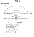
- a digital versatile disk is 1.2mm in thickness and 120mm in diameter like a CD as shown in Fig. 2 .
- a DVD also has a center hole of 15mm diameter and a clamping zone of 44mm encircling the center hole.
- a DVD When a DVD is normally placed into a disk device, its recording layer, which has pit patterns, is approximately 0.6mm from an objective lens of an optical pickup equipped in the disk device.
- the objective lens for a DVD has a NA of 0.6, which is relatively large.
- a HD-DVD which is currently being commercialized, is 1.2mm in thickness and 120mm in diameter, like a CD as shown in Fig. 3 .
- a HD-DVD also has a center hole of 15mm diameter and a clamping zone of 44mm encircling the center hole. If a HD-DVD is normally placed into a disk device, there will be a 0.1mm gap between its recording layer, which also has pit patterns, and an objective lens of an optical pickup for a HD-DVD, which has the largest NA of 0.85.
- the optical pickup for a HD-DVD uses a laser beam of shorter wavelength than for a CD or a DVD to record or reproduce signals in high density.
- HD-DVD uses an objective lens that is situated closer to the recording layer, that uses a laser beam of shorter wavelength, and that has a greater NA. According to these conditions, it is possible to concentrate a stronger intensity of light on a smaller beam spot formed on the high-density pit patterns of the recording layer of the HD-DVD. Consequently, the transmitting distance of a laser beam of shorter wavelength is shortened, and the variation of the laser beam and its spherical aberration are minimized.
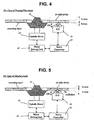
- a HD-DVD 10 is normally placed onto a turntable 11 installed in a disk device as shown in Fig. 4 , a conventional servo-controlling operation for a spindle motor 12 by a motor driving unit 13 and a servo controller 15 is conducted to rotate the placed HD-DVD 10 at a constant and high speed. While the HD-DVD 10 is rotating, a focusing-servo operation is conducted to focus a laser beam for an optical pickup 14 exactly onto the recording layer 9. This operation is performed by moving the objective lens OL of the optical pickup 14 in an up and down direction within an operating distance OD. If a laser beam is exactly in focus, then reproduction (or recording) of high-density pit patterns can be accomplished.
- the HD-DVD 10 when the HD-DVD 10 is misplaced onto the turntable 11 by, for example, being placed upside down as shown in Fig. 5 , the HD-DVD 10 will still be rotated at a constant and high speed by the combined servo-controlling operation by the spindle motor 12, the motor driving unit 13, and the servo controller 15. However, if the HD-DVD 10 has been placed upside down, the gap between the recording layer 9 and the objective lens OL of the optical pickup 14 is 1.1mm greater in comparison with a normally-placed HD-DVD.
- the servo controller 15 supervising the focusing-servo operation continues to move the objective lens OL upward to the maximum movable distance 'OD_Max' until the laser beam is correctly focused.
- the objective lens OL will collide with the misplaced HD-DVD 10. Consequently, the HD-DVD 10, the objective lens OL, and/or the servo-mechanism would be irreparably damaged.
- JP 2000322765 A EP 0 567 318 B1 , US 5,418,766 A EP 1 067 538 A1 and JP 10269620 .
- a recording medium for storing data comprises a disk having first and second surfaces, the disk including a recording area and a clamping area and defining a center hole for receiving a spindle therein, wherein the clamping area includes corresponding first and second clamping surfaces; a recording layer coplanarly disposed in the disk, wherein the recording layer is in closer proximity to the second surface of the disk; and the clamping area at least partially having a protruding portion on the first clamping surface so that the disk is raised from the spindle when the disk is inserted by placing the first clamping surface on the spindle.
- the clamping area at the protruding portion has first and second thicknesses measured from a center plane of the disk, the first thickness measured in a direction extending from the center plane of the disk toward the first surface of the disk and the second thickness measured in a direction toward the second surface, wherein the first thickness is greater than the second thickness.
- the difference between the first and the second thicknesses is approximately 0.1mm to 0.6mm.
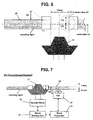
- Fig. 6 is a sectional view of the first preferred embodiment of a high-density disk structured according to the present invention.
- the embodiment of a high-density disk for example, a HD-DVD according to the present invention has same dimension as a conventional HD-DVD depicted in Fig. 3 , namely, 1.2mm in thickness and 120mm in diameter, a center hole of 15mm diameter and a clamping zone (or clamping area) of 44mm diameter encircling the center hole.
- a conventional HD-DVD depicted in Fig. 3 namely, 1.2mm in thickness and 120mm in diameter, a center hole of 15mm diameter and a clamping zone (or clamping area) of 44mm diameter encircling the center hole.
- the present HD-DVD 20 of Fig. 6 is normally placed into a disk device, its recording layer, which contains pit patterns, would be approximately 0.1mm from the objective lens of an optical pickup as mentioned before.
- the present HD-DVD 20 in Fig. 6 has a clamping zone structured such that the thickness (P1 and P2) of each side, P1 and P2, are different, namely and preferably P1 is greater than P2.
- P1 and P2 are created by bisecting the clamping zone with an imaginary longitudinal center plane "c."
- the opposite side of the recording side which is the recording layer, protrudes above the disk's upper surface, indicated by D1 in Fig. 6 .
- the clamping zone may have partial regions that are protruding or raised with respect to the recording or reading area of the disk.
- the height D 1 preferably ranges from about 0.1mm to 0.6mm and guarantees a marginal gap between the present disk and the objective lens for preventing a collision between the objective lens of an optical pickup even though the objective lens moves upward to the maximum movable distance on the condition that the present high-density disk has been placed upside down.
- other suitable height D1 may also be used without deviating from the present invention.
- the disk 20 structured as above is placed normally on a spindle or turntable 11 equipped in a disk device as shown in Fig. 7 , the non-protruding side of the clamping zone of the present disk 20 is in contact with the turntable 11. Consequently, the disk 20 is normally clamped the same as a conventional disk.
- a conventional servo-controlling operation characterized by the operation of the spindle motor 12, the motor driving unit 13 and the servo controller 15, is conducted to rotate the right-clamped disk 20 at a constant and high speed.
- a focusing-servo operation is conducted to focus a laser beam exactly onto a recording layer by moving the objective lens OL of the optical pickup 14 up and down within the operating distance OD. Once the laser beam is exactly focused, reproduction (or recording) of the high-density pit patterns begins.
- the present disk 20 is placed upside down on the turntable 11 as shown in Fig. 8 , the protruding side of the clamping zone of the present disk 20 is in contact with the turntable 11. Consequently, the surface of the disk 20 is raised by the height D 1 over normal placement, which ranges from about 0.1mm to 0.6mm. In other words, the separation distance between the objective lens and the disk 20 has increased due to the added thickness of the clamping zone.
- the objective lens OL of the optical pickup 14 moves up to the maximum distance to acquire the exact focus while the misplaced disk 20 is rotating at a high speed, the objective lens OL will not collide with the surface of the misplaced disk 20, due to the marginal gap D 1 created by the protruding side of the clamping zone. Furthermore, because the recording layer, and the high-density pit patterns contained within, is also further apart from the objective lens OL than in normal placement, the focusing operation will fail. As a result, the misplacement of the disk would be judged as "no disk.” Because a judgment of "no disk" ceases the focusing operation, a collision between the objective lens OL and the disk 20 is avoided.
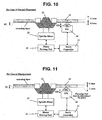
- Fig. 9 is a sectional view of the second preferred embodiment of a high-density disk structured according to the present invention.
- the second embodiment of a high-density disk 21 according to the present invention has a clamping zone structured such that the thickness of each side, P1 and P2, which are created by bisecting the clamping zone with an imaginary longitudinal center plane "c," are different. Namely, P1 is greater than P2, where both P1 and P2 are both greater than one-half of the whole thickness of the disk 21 as shown in Fig. 9 .
- the side opposite to the recording side protrudes from disk surface a greater distance than of the recording side. As shown in Fig. 9 , the height D1, which ranges approximately from 0.1mm to 0.6mm, is greater than D2, which is located on the recording side.
- the protruding height D2 of the recording side is preferably determined to be within a range that ensures a successful focus of the pit patterns within the recording layer by the objective lens OL as it moves up and down within the operating distance OD on the condition that the disk 21 has been normally placed.
- the recording layer of the disk 21 is further apart from the objective lens OL by the small protruding height D2 than that of a conventional disk.
- the distance D2 is within a range ensuring successful focus as described above, it is possible to focus a light beam on the recording layer so that reproduction (or recording) of the high-density pit patterns can be conducted.
- the objective lens OL of the optical pickup 14 can move up to the maximum distance to acquire an exact focus while the misplaced disk 21 is rotating at a high speed without colliding with the surface of the misplaced disk 21.
- the recording layer is further apart from the objective lens OL by the height D1
- the focusing operation will fail, resulting in that the disk misplacement would be judged as "no disk.” Because judgment of 'no disk' ceases all focusing operations, a collision between the objective lens OL and the disk 21 is avoided.
- Fig. 12 is a sectional view of the third preferred embodiment of a high-density disk structured according to the present invention.
- the third embodiment of a high-density disk 22 according to the present invention has a clamping zone structured such that the thickness of each side, P1 and P2, which are created by bisecting the high-density disk 22 with an imaginary longitudinal center plane "c."
- P1 is greater than P2 and P1 is thicker than one-half of the whole thickness of the disk 22 but P2 is thinner than one-half of the whole thickness of the disk 22.
- the side opposite to the recording side protrudes from disk surface by the height D1, which ranges from approximately 0.1mm to 0.6mm, whereas the clamping zone on the recording side is indented by a height less than D1.
- the indented side of the clamping zone which is in contact with a holder of the turntable 11, allows the recording layer of the disk 22 to be appropriately apart from the optical pickup 14.
- the distance between the recording layer and the objective lens OL for this embodiment is longer within the acceptable range for a conventional disk.
- the surface of the disk 22 is raised by a height D1, which ranges from 0.1mm to 0.6mm. Therefore, although the objective lens OL of the optical pickup 14 can move up to the maximum distance to acquire an exact focus on the recording layer, the objective lens OL will not collide with the surface of the misplaced disk 22. As described above, the misplacement would result in a reading of "no disk,” which would cease the focusing operation and avoiding a collision between the objective lens OL and the disk 22.
- the protrusion and/or indentation of the claming zone may be shaped variously other than the aforementioned embodiments, for example, a clamping zone may be protruded or indented partially.
- the invention may be applicable to a rewritable high-density disk as well as a read-only high-density disk.
- the present invention may also be applied to any other rewritable or read-only type disk medium.
- the present embodiments are therefore to be considered in all respects as illustrative and not restrictive, the scope of the invention being indicated by the appended claims.
Applications Claiming Priority (3)
| Application Number | Priority Date | Filing Date | Title |
|---|---|---|---|
| KR10-2001-0026250A KR100378086B1 (ko) | 2001-05-14 | 2001-05-14 | 클랭핑 영역의 상하면이 서로다른 높이를 갖는 고밀도 광디스크 |
| KR2001026250 | 2001-05-14 | ||
| EP02005461A EP1258872B1 (en) | 2001-05-14 | 2002-03-09 | High-density disk having a protruding portion on a clamping zone |
Related Parent Applications (1)
| Application Number | Title | Priority Date | Filing Date |
|---|---|---|---|
| EP02005461A Division EP1258872B1 (en) | 2001-05-14 | 2002-03-09 | High-density disk having a protruding portion on a clamping zone |
Publications (2)
| Publication Number | Publication Date |
|---|---|
| EP1605451A1 EP1605451A1 (en) | 2005-12-14 |
| EP1605451B1 true EP1605451B1 (en) | 2009-04-08 |
Family
ID=19709456
Family Applications (2)
| Application Number | Title | Priority Date | Filing Date |
|---|---|---|---|
| EP05013739A Expired - Lifetime EP1605451B1 (en) | 2001-05-14 | 2002-03-09 | High-density disk recording medium having a protruding side on a clamping zone |
| EP02005461A Expired - Lifetime EP1258872B1 (en) | 2001-05-14 | 2002-03-09 | High-density disk having a protruding portion on a clamping zone |
Family Applications After (1)
| Application Number | Title | Priority Date | Filing Date |
|---|---|---|---|
| EP02005461A Expired - Lifetime EP1258872B1 (en) | 2001-05-14 | 2002-03-09 | High-density disk having a protruding portion on a clamping zone |
Country Status (10)
| Country | Link |
|---|---|
| US (2) | US7012880B2 (ko) |
| EP (2) | EP1605451B1 (ko) |
| JP (1) | JP4094877B2 (ko) |
| KR (1) | KR100378086B1 (ko) |
| CN (3) | CN100372007C (ko) |
| AT (2) | ATE445898T1 (ko) |
| DE (2) | DE60231924D1 (ko) |
| ES (2) | ES2332036T3 (ko) |
| HK (1) | HK1100193A1 (ko) |
| PT (1) | PT1258872E (ko) |
Families Citing this family (17)
| Publication number | Priority date | Publication date | Assignee | Title |
|---|---|---|---|---|
| KR100378086B1 (ko) * | 2001-05-14 | 2003-03-29 | 엘지전자 주식회사 | 클랭핑 영역의 상하면이 서로다른 높이를 갖는 고밀도 광디스크 |
| US6667953B2 (en) * | 2001-12-21 | 2003-12-23 | Seth Matson | Optical disk protector and method of use |
| US7617507B2 (en) * | 2003-06-03 | 2009-11-10 | Lg Electronics Inc. | High-density recording medium and recording and/or reproducing device therefor |
| KR100944992B1 (ko) * | 2003-06-03 | 2010-03-05 | 엘지전자 주식회사 | 정보 영역의 두께와 클램핑 영역의 두께가 서로 다르게형성된 고밀도 광디스크와, 그에 따른 광디스크 장치 |
| KR100987437B1 (ko) | 2003-08-14 | 2010-10-13 | 엘지전자 주식회사 | 기록매체, 기록방법 및 기록장치 |
| CN100449623C (zh) * | 2003-10-31 | 2009-01-07 | 巨擘科技股份有限公司 | 光盘片基板、光盘片及其制造方法 |
| CN100444263C (zh) * | 2004-04-06 | 2008-12-17 | 建兴电子科技股份有限公司 | 具有侦测倒置功能的光驱及其方法 |
| KR101074737B1 (ko) | 2005-04-22 | 2011-10-19 | 주식회사 히타치엘지 데이터 스토리지 코리아 | 라벨 프린팅이 가능한 광디스크 및 이의 포커싱방법 |
| FR2887678B1 (fr) * | 2005-06-28 | 2007-09-28 | Digital Valley | Disque numerique universel |
| JP2007026507A (ja) * | 2005-07-14 | 2007-02-01 | Matsushita Electric Ind Co Ltd | 光ピックアップ装置 |
| EP1923873A1 (en) * | 2006-11-15 | 2008-05-21 | ODS Technology GmbH | EcoDisc |
| DE06023769T1 (de) * | 2006-11-15 | 2008-10-23 | Ods Technology Gmbh | EcoDisc |
| EP2117003A3 (en) * | 2006-11-20 | 2010-01-13 | EcoDisc Technology AG | Smart video card |
| WO2008108676A1 (fr) * | 2007-03-06 | 2008-09-12 | Andrei Vladimirovich Tropillo | Support d'informations sous forme de disque |
| CN101807414A (zh) * | 2010-04-21 | 2010-08-18 | 江苏新广联科技股份有限公司 | 薄型光盘夹持区粘贴增厚的光盘和方法 |
| EP3699218A1 (de) * | 2019-02-22 | 2020-08-26 | Covestro Deutschland AG | Neue zweikomponenten-deckbeschichtungssysteme enthaltend polyasparaginsäureester |
| CN113412295B (zh) * | 2019-02-22 | 2023-08-25 | 科思创知识产权两合公司 | 包含多天冬氨酸酯的新型双组分清漆体系 |
Family Cites Families (34)
| Publication number | Priority date | Publication date | Assignee | Title |
|---|---|---|---|---|
| JPS59116942A (ja) * | 1982-12-23 | 1984-07-06 | Olympus Optical Co Ltd | オ−トフォ−カス装置 |
| JPH0636253B2 (ja) | 1983-08-18 | 1994-05-11 | シャープ株式会社 | 光メモリ円板 |
| US5448547A (en) * | 1987-12-01 | 1995-09-05 | Mitsui Petrochemical Industries, Ltd. | Information recording discs |
| JPH0731422Y2 (ja) * | 1987-12-01 | 1995-07-19 | 三井石油化学工業株式会社 | 光ディスク |
| US5235581A (en) * | 1990-08-09 | 1993-08-10 | Matsushita Electric Industrial Co., Ltd. | Optical recording/reproducing apparatus for optical disks with various disk substrate thicknesses |
| JPH05225609A (ja) | 1992-02-06 | 1993-09-03 | Tdk Corp | 光ディスク用基板および光ディスク |
| JP3377048B2 (ja) * | 1992-04-24 | 2003-02-17 | パイオニア株式会社 | 追記型光ディスクの再生装置および再生方法 |
| JPH0814929B2 (ja) * | 1992-12-28 | 1996-02-14 | ティアック株式会社 | 光ディスク装置 |
| JP2973155B2 (ja) * | 1993-10-29 | 1999-11-08 | 株式会社名機製作所 | ディスク基板並びに該ディスク基板の成形に用いる成形金型 |
| KR100200838B1 (ko) * | 1995-01-24 | 1999-06-15 | 윤종용 | 다층 디스크 |
| DE19631319A1 (de) | 1995-08-15 | 1997-02-20 | Minnesota Mining & Mfg | Platte zur optischen Datenspeicherung |
| JPH09204686A (ja) | 1996-01-29 | 1997-08-05 | Sony Disc Technol:Kk | 光デイスク及び光デイスクの製造方法 |
| JPH10188508A (ja) | 1996-12-25 | 1998-07-21 | Sony Corp | 光学ディスク |
| JPH10283683A (ja) | 1997-02-05 | 1998-10-23 | Sony Corp | 光記録媒体及びその製造方法 |
| JPH10269621A (ja) * | 1997-03-25 | 1998-10-09 | Sony Corp | 光ディスク基板及びこれを用いた光ディスク |
| JPH10269620A (ja) | 1997-03-26 | 1998-10-09 | Sanyo Electric Co Ltd | 光ディスク |
| JP3177485B2 (ja) * | 1997-08-05 | 2001-06-18 | 三洋電機株式会社 | 光ディスク |
| CN1224216A (zh) * | 1997-11-24 | 1999-07-28 | 三星电子株式会社 | 鉴别可重写光盘的装置和方法 |
| JP3988236B2 (ja) * | 1998-02-13 | 2007-10-10 | ヤマハ株式会社 | 光ディスク |
| US6214430B1 (en) * | 1998-04-10 | 2001-04-10 | Lg Electronics Inc. | Disc recording medium and method of fabricating the same |
| AU1078800A (en) | 1998-11-06 | 2000-05-29 | Hitachi Maxell, Ltd. | Optical disk, disk substrate, and drive |
| JP2000251324A (ja) | 1999-02-26 | 2000-09-14 | Sony Corp | 光記録媒体 |
| JP4158262B2 (ja) * | 1999-02-26 | 2008-10-01 | ソニー株式会社 | 情報記録再生装置および方法ならびに記録媒体 |
| JP2000322765A (ja) * | 1999-05-12 | 2000-11-24 | Sharp Corp | 光記録媒体 |
| JP2001006210A (ja) * | 1999-06-22 | 2001-01-12 | Sony Corp | 光記録媒体及びディスクカートリッジ |
| JP2001006264A (ja) * | 1999-06-22 | 2001-01-12 | Matsushita Electric Ind Co Ltd | 光ディスク記録再生装置 |
| JP4215923B2 (ja) | 2000-02-02 | 2009-01-28 | 株式会社ソニー・ディスクアンドデジタルソリューションズ | 光ディスク及びその射出圧縮成形用金型 |
| US6584067B2 (en) | 2000-03-03 | 2003-06-24 | Tosoh Corporation | Optical recording medium having a recording/reproducing area with a shaped region |
| EP1152407A3 (en) | 2000-04-25 | 2006-10-25 | Matsushita Electric Industrial Co., Ltd. | Optical disk, method for producing the same, and apparatus for producing the same |
| JP2002170279A (ja) | 2000-11-30 | 2002-06-14 | Sony Corp | 光学記録媒体およびその製造方法、ならびに射出成形装置 |
| KR100419211B1 (ko) | 2000-12-20 | 2004-02-19 | 삼성전자주식회사 | 디스크형 기록매체 |
| KR100378086B1 (ko) | 2001-05-14 | 2003-03-29 | 엘지전자 주식회사 | 클랭핑 영역의 상하면이 서로다른 높이를 갖는 고밀도 광디스크 |
| US6865745B2 (en) | 2001-08-10 | 2005-03-08 | Wea Manufacturing, Inc. | Methods and apparatus for reducing the shrinkage of an optical disc's clamp area and the resulting optical disc |
| KR100499479B1 (ko) | 2002-09-10 | 2005-07-05 | 엘지전자 주식회사 | 고밀도 광디스크 구조 |
-
2001
- 2001-05-14 KR KR10-2001-0026250A patent/KR100378086B1/ko active IP Right Grant
-
2002
- 2002-03-05 US US10/097,547 patent/US7012880B2/en not_active Expired - Lifetime
- 2002-03-09 DE DE60231924T patent/DE60231924D1/de not_active Expired - Lifetime
- 2002-03-09 EP EP05013739A patent/EP1605451B1/en not_active Expired - Lifetime
- 2002-03-09 ES ES02005461T patent/ES2332036T3/es not_active Expired - Lifetime
- 2002-03-09 AT AT02005461T patent/ATE445898T1/de not_active IP Right Cessation
- 2002-03-09 PT PT02005461T patent/PT1258872E/pt unknown
- 2002-03-09 AT AT05013739T patent/ATE428172T1/de not_active IP Right Cessation
- 2002-03-09 ES ES05013739T patent/ES2321950T3/es not_active Expired - Lifetime
- 2002-03-09 EP EP02005461A patent/EP1258872B1/en not_active Expired - Lifetime
- 2002-03-09 DE DE60233995T patent/DE60233995D1/de not_active Expired - Lifetime
- 2002-04-02 JP JP2002099720A patent/JP4094877B2/ja not_active Expired - Fee Related
- 2002-05-14 CN CNB2004100901409A patent/CN100372007C/zh not_active Expired - Lifetime
- 2002-05-14 CN CNB021191832A patent/CN1266691C/zh not_active Expired - Fee Related
- 2002-05-14 CN CN2006100923604A patent/CN1870154B/zh not_active Expired - Fee Related
-
2004
- 2004-07-16 US US10/892,879 patent/US7515524B2/en not_active Expired - Fee Related
-
2007
- 2007-05-29 HK HK07105729.0A patent/HK1100193A1/xx not_active IP Right Cessation
Also Published As
| Publication number | Publication date |
|---|---|
| EP1605451A1 (en) | 2005-12-14 |
| ES2332036T3 (es) | 2010-01-25 |
| CN1266691C (zh) | 2006-07-26 |
| US20040257941A1 (en) | 2004-12-23 |
| DE60231924D1 (de) | 2009-05-20 |
| CN1870154A (zh) | 2006-11-29 |
| ATE428172T1 (de) | 2009-04-15 |
| CN1870154B (zh) | 2012-05-23 |
| CN1385848A (zh) | 2002-12-18 |
| HK1100193A1 (en) | 2007-09-07 |
| CN100372007C (zh) | 2008-02-27 |
| DE60233995D1 (de) | 2009-11-26 |
| EP1258872A2 (en) | 2002-11-20 |
| KR100378086B1 (ko) | 2003-03-29 |
| JP2002342978A (ja) | 2002-11-29 |
| US7012880B2 (en) | 2006-03-14 |
| US7515524B2 (en) | 2009-04-07 |
| EP1258872B1 (en) | 2009-10-14 |
| PT1258872E (pt) | 2009-10-22 |
| EP1258872A3 (en) | 2004-03-24 |
| US20020167892A1 (en) | 2002-11-14 |
| ATE445898T1 (de) | 2009-10-15 |
| JP4094877B2 (ja) | 2008-06-04 |
| ES2321950T3 (es) | 2009-06-15 |
| CN1612244A (zh) | 2005-05-04 |
| KR20020087222A (ko) | 2002-11-22 |
Similar Documents
| Publication | Publication Date | Title |
|---|---|---|
| EP1605451B1 (en) | High-density disk recording medium having a protruding side on a clamping zone | |
| EP0810598A2 (en) | Optical disk apparatus | |
| JP4141622B2 (ja) | ピックアップ装置 | |
| EP1274075B1 (en) | High-density disk recording medium having a reflecting surface and manufacturing method thereof | |
| US20050007901A1 (en) | Optical disc apparatus | |
| US7484231B2 (en) | High-density disk recording medium having an asymmetrically-shaped center hole and manufacturing method thereof | |
| KR100713833B1 (ko) | 광디스크 오 삽입 검출장치 | |
| EP1488419B1 (en) | Servo-controlling method of an optical disk apparatus | |
| JP3575181B2 (ja) | 光学記録媒体の記録及び/又は再生装置及びそれに用いられる光学ピックアップ | |
| KR100944992B1 (ko) | 정보 영역의 두께와 클램핑 영역의 두께가 서로 다르게형성된 고밀도 광디스크와, 그에 따른 광디스크 장치 | |
| US20040240364A1 (en) | Optical recording medium and apparatus for recording/reproducing data on or from the same | |
| WO2004025634A1 (en) | High-density disk recording medium and a driving method thereof | |
| KR20030000899A (ko) | 고밀도 광디스크 및 그 구동장치 | |
| JP2708024B2 (ja) | 光ディスクの判別方法 | |
| KR20020087668A (ko) | 고밀도 광디스크 및 그 구동장치 | |
| KR20100003348A (ko) | 정보 영역의 두께와 클램핑 영역의 두께가 서로 다르게 형성된 고밀도 광디스크와, 그에 따른 광디스크 장치 | |
| KR20030000902A (ko) | 고밀도 광디스크 및 그 구동장치 | |
| KR20030001946A (ko) | 광디스크의 오 삽입 판별장치 및 방법 | |
| JPH0567362A (ja) | 光磁気記録装置 | |
| KR20030069544A (ko) | 고밀도 광디스크 및 그 광기록재생장치 | |
| TW200402692A (en) | Device and method for discriminating optical recording medium | |
| JP2004022065A (ja) | 光情報記録媒体及び光情報再生装置 | |
| KR20020097447A (ko) | 고밀도 광디스크 및 그 제조방법 |
Legal Events
| Date | Code | Title | Description |
|---|---|---|---|
| PUAI | Public reference made under article 153(3) epc to a published international application that has entered the european phase |
Free format text: ORIGINAL CODE: 0009012 |
|
| 17P | Request for examination filed |
Effective date: 20050625 |
|
| AC | Divisional application: reference to earlier application |
Ref document number: 1258872 Country of ref document: EP Kind code of ref document: P |
|
| AK | Designated contracting states |
Kind code of ref document: A1 Designated state(s): AT BE CH CY DE DK ES FI FR GB GR IE IT LI LU MC NL PT SE TR |
|
| AKX | Designation fees paid |
Designated state(s): AT BE CH CY DE DK ES FI FR GB GR IE IT LI LU MC NL PT SE TR |
|
| 17Q | First examination report despatched |
Effective date: 20071030 |
|
| GRAP | Despatch of communication of intention to grant a patent |
Free format text: ORIGINAL CODE: EPIDOSNIGR1 |
|
| GRAS | Grant fee paid |
Free format text: ORIGINAL CODE: EPIDOSNIGR3 |
|
| GRAA | (expected) grant |
Free format text: ORIGINAL CODE: 0009210 |
|
| AC | Divisional application: reference to earlier application |
Ref document number: 1258872 Country of ref document: EP Kind code of ref document: P |
|
| AK | Designated contracting states |
Kind code of ref document: B1 Designated state(s): AT BE CH CY DE DK ES FI FR GB GR IE IT LI LU MC NL PT SE TR |
|
| REG | Reference to a national code |
Ref country code: GB Ref legal event code: FG4D |
|
| REG | Reference to a national code |
Ref country code: CH Ref legal event code: EP |
|
| REG | Reference to a national code |
Ref country code: IE Ref legal event code: FG4D |
|
| REF | Corresponds to: |
Ref document number: 60231924 Country of ref document: DE Date of ref document: 20090520 Kind code of ref document: P |
|
| REG | Reference to a national code |
Ref country code: ES Ref legal event code: FG2A Ref document number: 2321950 Country of ref document: ES Kind code of ref document: T3 |
|
| PG25 | Lapsed in a contracting state [announced via postgrant information from national office to epo] |
Ref country code: PT Free format text: LAPSE BECAUSE OF FAILURE TO SUBMIT A TRANSLATION OF THE DESCRIPTION OR TO PAY THE FEE WITHIN THE PRESCRIBED TIME-LIMIT Effective date: 20090908 Ref country code: AT Free format text: LAPSE BECAUSE OF FAILURE TO SUBMIT A TRANSLATION OF THE DESCRIPTION OR TO PAY THE FEE WITHIN THE PRESCRIBED TIME-LIMIT Effective date: 20090408 |
|
| PG25 | Lapsed in a contracting state [announced via postgrant information from national office to epo] |
Ref country code: SE Free format text: LAPSE BECAUSE OF FAILURE TO SUBMIT A TRANSLATION OF THE DESCRIPTION OR TO PAY THE FEE WITHIN THE PRESCRIBED TIME-LIMIT Effective date: 20090708 |
|
| PG25 | Lapsed in a contracting state [announced via postgrant information from national office to epo] |
Ref country code: DK Free format text: LAPSE BECAUSE OF FAILURE TO SUBMIT A TRANSLATION OF THE DESCRIPTION OR TO PAY THE FEE WITHIN THE PRESCRIBED TIME-LIMIT Effective date: 20090408 |
|
| PLBE | No opposition filed within time limit |
Free format text: ORIGINAL CODE: 0009261 |
|
| STAA | Information on the status of an ep patent application or granted ep patent |
Free format text: STATUS: NO OPPOSITION FILED WITHIN TIME LIMIT |
|
| PG25 | Lapsed in a contracting state [announced via postgrant information from national office to epo] |
Ref country code: BE Free format text: LAPSE BECAUSE OF FAILURE TO SUBMIT A TRANSLATION OF THE DESCRIPTION OR TO PAY THE FEE WITHIN THE PRESCRIBED TIME-LIMIT Effective date: 20090408 |
|
| 26N | No opposition filed |
Effective date: 20100111 |
|
| PG25 | Lapsed in a contracting state [announced via postgrant information from national office to epo] |
Ref country code: MC Free format text: LAPSE BECAUSE OF NON-PAYMENT OF DUE FEES Effective date: 20100331 Ref country code: GR Free format text: LAPSE BECAUSE OF FAILURE TO SUBMIT A TRANSLATION OF THE DESCRIPTION OR TO PAY THE FEE WITHIN THE PRESCRIBED TIME-LIMIT Effective date: 20090709 |
|
| REG | Reference to a national code |
Ref country code: CH Ref legal event code: PL |
|
| PG25 | Lapsed in a contracting state [announced via postgrant information from national office to epo] |
Ref country code: IE Free format text: LAPSE BECAUSE OF NON-PAYMENT OF DUE FEES Effective date: 20100309 |
|
| PG25 | Lapsed in a contracting state [announced via postgrant information from national office to epo] |
Ref country code: LI Free format text: LAPSE BECAUSE OF NON-PAYMENT OF DUE FEES Effective date: 20100331 Ref country code: CH Free format text: LAPSE BECAUSE OF NON-PAYMENT OF DUE FEES Effective date: 20100331 |
|
| PG25 | Lapsed in a contracting state [announced via postgrant information from national office to epo] |
Ref country code: CY Free format text: LAPSE BECAUSE OF FAILURE TO SUBMIT A TRANSLATION OF THE DESCRIPTION OR TO PAY THE FEE WITHIN THE PRESCRIBED TIME-LIMIT Effective date: 20090408 |
|
| PG25 | Lapsed in a contracting state [announced via postgrant information from national office to epo] |
Ref country code: FI Free format text: LAPSE BECAUSE OF FAILURE TO SUBMIT A TRANSLATION OF THE DESCRIPTION OR TO PAY THE FEE WITHIN THE PRESCRIBED TIME-LIMIT Effective date: 20090408 Ref country code: LU Free format text: LAPSE BECAUSE OF NON-PAYMENT OF DUE FEES Effective date: 20100309 |
|
| PG25 | Lapsed in a contracting state [announced via postgrant information from national office to epo] |
Ref country code: TR Free format text: LAPSE BECAUSE OF FAILURE TO SUBMIT A TRANSLATION OF THE DESCRIPTION OR TO PAY THE FEE WITHIN THE PRESCRIBED TIME-LIMIT Effective date: 20090408 |
|
| REG | Reference to a national code |
Ref country code: FR Ref legal event code: PLFP Year of fee payment: 15 |
|
| REG | Reference to a national code |
Ref country code: FR Ref legal event code: PLFP Year of fee payment: 16 |
|
| REG | Reference to a national code |
Ref country code: FR Ref legal event code: PLFP Year of fee payment: 17 |
|
| PGFP | Annual fee paid to national office [announced via postgrant information from national office to epo] |
Ref country code: NL Payment date: 20210209 Year of fee payment: 20 Ref country code: FR Payment date: 20210216 Year of fee payment: 20 Ref country code: IT Payment date: 20210309 Year of fee payment: 20 |
|
| PGFP | Annual fee paid to national office [announced via postgrant information from national office to epo] |
Ref country code: DE Payment date: 20210208 Year of fee payment: 20 Ref country code: GB Payment date: 20210216 Year of fee payment: 20 |
|
| PGFP | Annual fee paid to national office [announced via postgrant information from national office to epo] |
Ref country code: ES Payment date: 20210413 Year of fee payment: 20 |
|
| REG | Reference to a national code |
Ref country code: DE Ref legal event code: R071 Ref document number: 60231924 Country of ref document: DE Ref country code: NL Ref legal event code: MK Effective date: 20220308 |
|
| REG | Reference to a national code |
Ref country code: GB Ref legal event code: PE20 Expiry date: 20220308 |
|
| PG25 | Lapsed in a contracting state [announced via postgrant information from national office to epo] |
Ref country code: GB Free format text: LAPSE BECAUSE OF EXPIRATION OF PROTECTION Effective date: 20220308 |
|
| REG | Reference to a national code |
Ref country code: ES Ref legal event code: FD2A Effective date: 20220624 |
|
| PG25 | Lapsed in a contracting state [announced via postgrant information from national office to epo] |
Ref country code: ES Free format text: LAPSE BECAUSE OF EXPIRATION OF PROTECTION Effective date: 20220310 |