EP1258872B1 - High-density disk having a protruding portion on a clamping zone - Google Patents
High-density disk having a protruding portion on a clamping zone Download PDFInfo
- Publication number
- EP1258872B1 EP1258872B1 EP02005461A EP02005461A EP1258872B1 EP 1258872 B1 EP1258872 B1 EP 1258872B1 EP 02005461 A EP02005461 A EP 02005461A EP 02005461 A EP02005461 A EP 02005461A EP 1258872 B1 EP1258872 B1 EP 1258872B1
- Authority
- EP
- European Patent Office
- Prior art keywords
- disk
- clamping
- density
- objective lens
- clamping zone
- Prior art date
- Legal status (The legal status is an assumption and is not a legal conclusion. Google has not performed a legal analysis and makes no representation as to the accuracy of the status listed.)
- Expired - Lifetime
Links
- 230000003287 optical effect Effects 0.000 claims abstract description 27
- 239000000758 substrate Substances 0.000 description 2
- 230000004075 alteration Effects 0.000 description 1
- 239000012141 concentrate Substances 0.000 description 1
- 238000001514 detection method Methods 0.000 description 1
- 238000007373 indentation Methods 0.000 description 1
- 238000000926 separation method Methods 0.000 description 1
Images


Classifications
-
- G—PHYSICS
- G11—INFORMATION STORAGE
- G11B—INFORMATION STORAGE BASED ON RELATIVE MOVEMENT BETWEEN RECORD CARRIER AND TRANSDUCER
- G11B7/00—Recording or reproducing by optical means, e.g. recording using a thermal beam of optical radiation by modifying optical properties or the physical structure, reproducing using an optical beam at lower power by sensing optical properties; Record carriers therefor
- G11B7/002—Recording, reproducing or erasing systems characterised by the shape or form of the carrier
-
- G—PHYSICS
- G11—INFORMATION STORAGE
- G11B—INFORMATION STORAGE BASED ON RELATIVE MOVEMENT BETWEEN RECORD CARRIER AND TRANSDUCER
- G11B7/00—Recording or reproducing by optical means, e.g. recording using a thermal beam of optical radiation by modifying optical properties or the physical structure, reproducing using an optical beam at lower power by sensing optical properties; Record carriers therefor
- G11B7/08—Disposition or mounting of heads or light sources relatively to record carriers
- G11B7/085—Disposition or mounting of heads or light sources relatively to record carriers with provision for moving the light beam into, or out of, its operative position or across tracks, otherwise than during the transducing operation, e.g. for adjustment or preliminary positioning or track change or selection
- G11B7/08505—Methods for track change, selection or preliminary positioning by moving the head
- G11B7/08511—Methods for track change, selection or preliminary positioning by moving the head with focus pull-in only
-
- G—PHYSICS
- G11—INFORMATION STORAGE
- G11B—INFORMATION STORAGE BASED ON RELATIVE MOVEMENT BETWEEN RECORD CARRIER AND TRANSDUCER
- G11B23/00—Record carriers not specific to the method of recording or reproducing; Accessories, e.g. containers, specially adapted for co-operation with the recording or reproducing apparatus ; Intermediate mediums; Apparatus or processes specially adapted for their manufacture
- G11B23/0014—Record carriers not specific to the method of recording or reproducing; Accessories, e.g. containers, specially adapted for co-operation with the recording or reproducing apparatus ; Intermediate mediums; Apparatus or processes specially adapted for their manufacture record carriers not specifically of filamentary or web form
- G11B23/0021—Record carriers not specific to the method of recording or reproducing; Accessories, e.g. containers, specially adapted for co-operation with the recording or reproducing apparatus ; Intermediate mediums; Apparatus or processes specially adapted for their manufacture record carriers not specifically of filamentary or web form discs
- G11B23/0028—Details
- G11B23/0035—Details means incorporated in the disc, e.g. hub, to enable its guiding, loading or driving
-
- G—PHYSICS
- G11—INFORMATION STORAGE
- G11B—INFORMATION STORAGE BASED ON RELATIVE MOVEMENT BETWEEN RECORD CARRIER AND TRANSDUCER
- G11B7/00—Recording or reproducing by optical means, e.g. recording using a thermal beam of optical radiation by modifying optical properties or the physical structure, reproducing using an optical beam at lower power by sensing optical properties; Record carriers therefor
- G11B7/24—Record carriers characterised by shape, structure or physical properties, or by the selection of the material
- G11B7/24097—Structures for detection, control, recording operation or replay operation; Special shapes or structures for centering or eccentricity prevention; Arrangements for testing, inspecting or evaluating; Containers, cartridges or cassettes
Definitions
- the present invention relates to a high-density disk structure preventing collision of ain optical pickup's objective lens with a high-density disk which is placed upside down in a disk device being able to reproduce and record signals from/to a high-density disk such as a high-density digital versatile disk (called "HD-DVD” hereinafter).
- a high-density disk such as a high-density digital versatile disk (called "HD-DVD” hereinafter).
- JP 10269620 (abstract) relates to an optical disk having a substrate which passes light beams for reading and writing. With respect to a center plane of the disk, a recording layer is located in a portion of the disk which is distant from a light beam entrance side. A central portion of the substrate has a protrusion on the light beam entrance side.
- a compact disk is 1.2mm in thickness and 120mm in diameter as shown in Fig. 1 .
- a CD has a center hole of 15mm diameter and a clamping zone of 44mm, which encircles the center hole where the clamping zone is clamped by a clamper on a spindle or a turntable installed in a disk device.
- a CD When a CD is normally placed into a disk device, its recording layer, which has pit patterns, is approximately 1.2mm from an objective lens of an optical pickup equipped in the disk device.
- the objective lens for a CD has a numerical aperture (NA) of 0.45, which is relatively small.
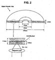
- a digital versatile disk is 1.2mm in thickness and 120mm in diameter like a CD as shown in Fig 2 .
- a DVD also has a center hole of 15mm diameter and a clamping zone of 44mm encircling the center hole.
- a DVD When a DVD is normally placed into a disk device, its recording layer, which has pit patterns, is approximately 0.6mm from an objective lens of an optical pickup equipped in the disk device.
- the objective lens for a DVD has a NA of 0.6, which is relatively large.
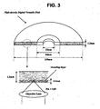
- a HD-DVD which is currently being commercialized, is 1.2mm in thickness and 120mm in diameter, like a CD as shown in Fig. 3 .
- a HD-DVD also has a center hole of 15mm diameter and a clamping zone of 44mm encircling the center hole. If a HD-DVD is normally placed into a disk device, there will be a 0.1 mm gap between its recording layer, which also has pit patterns, and an objective lens of an optical pickup for a HD-DVD, which has the largest NA of 0.85.
- the optical pickup for a HD-DVD uses a laser beam of shorter wavelength than for a CD or a DVD to record or reproduce signals in high density.
- HD-DVD uses an objective lens that is situated closer to the recording layer, that uses a laser beam of shorter wavelength, and that has a greater NA. According to these conditions, it is possible to concentrate a stronger intensity of light on a smaller beam spot formed on the high-density pit patterns of the recording layer of the HD-DVD. Consequently, the transmitting distance of a laser beam of shorter wavelength is shortened, and the variation of the laser beam and its spherical aberration are minimized.
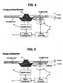
- a HD-DVD 10 is normally placed onto a turntable 11 installed in a disk device as shown in Fig. 4 , a conventional servo-controlling operation for a spindle motor 12 by a motor driving unit 13 and a servo controller 15 is conducted to rotate the placed HD-DVD 10 at a constant and high speed. While the HD-DVD 10 is rotating, a focusing-servo operation is conducted to focus a laser beam for an optical pickup 14 exactly onto the recording layer 9. This operation is performed by moving the objective lens OL of the optical pickup 14 in an up and down direction within an operating distance OD. If a laser beam is exactly in focus, then reproduction (or recording) of high-density pit patterns can be accomplished.
- the HD-DVD 10 when the HD-DVD 10 is misplaced onto the turntable 11 by, for example, being placed upside down as shown in Fig. 5 , the HD-DVD 10 will still be rotated at a constant and high speed by the combined servo-controlling operation by the spindle motor 12, the motor driving unit 13, and the servo controller 15. However, if the HD-DVD 10 has been placed upside down, the gap between the recording layer 9 and the objective lens OL of the optical pickup 14 is 1.1mm greater in comparison with a normally-placed HD-DVD.
- the servo controller 15 supervising the focusing-servo operation continues to move the objective lens OL upward to the maximum movable distance 'OD_Max' until the laser beam is correctly focused.
- the objective lens OL will collide with the misplaced HD-DVD 10. Consequently, the HD-DVD 10, the objective lens OL, and/or the servo-mechanism would be irreparably damaged.
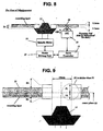
- Fig. 6 is a sectional view of the first preferred embodiment of a high-density disk structured according to the present invention.
- the embodiment of a high-density disk for example, a HD-DVD according to the present invention has same dimension as a conventional HD-DVD depicted in Fig. 3 , namely, 1.2mm in thickness and 120mm in diameter, a center hole of 15mm diameter and a clamping zone (or clamping area) of 44mm diameter encircling the center hole.
- a conventional HD-DVD depicted in Fig. 3 namely, 1.2mm in thickness and 120mm in diameter, a center hole of 15mm diameter and a clamping zone (or clamping area) of 44mm diameter encircling the center hole.
- the present HD-DVD 20 of Fig. 6 is normally placed into a disk device, its recording layer, which contains pit patterns, would be approximately 0.1mm from the objective lens of an optical pickup as mentioned before.
- the present HD-DVD 20 in Fig. 6 has a clamping zone structured such that the thickness (P1 and P2) of each side, P1 and P2, are different, namely and preferably P1 is greater than P2.
- P1 and P2 are created by bisecting the clamping zone with an imaginary longitudinal center plane "c."
- the opposite side of the recording side which is the recording layer, protrudes above the disk's upper surface, indicated by D1 in Fig. 6 .
- the clamping zone may have partial regions that are protruding or raised with respect to the recording or reading area of the disk.
- the height D1 preferably ranges from about 0.1mm to 0.6mm and guarantees a marginal gap between the present disk and the objective lens for preventing a collision between the objective lens of an optical pickup even though the objective lens moves upward to the maximum movable distance on the condition that the present high-density disk has been placed upside down.
- other suitable height D1 may also be used without deviating from the present invention.
- the disk 20 structured as above is placed normally on a spindle or turntable 11 equipped in a disk device as shown in Fig. 7 , the non-protruding side of the clamping zone of the present disk 20 is in contact with the turntable 11. Consequently, the disk 20 is normally clamped the same as a conventional disk.
- a conventional servo-controlling operation characterized by the operation of the spindle motor 12, the motor driving unit 13 and the servo controller 15, is conducted to rotate the right-clamped disk 20 at a constant and high speed.
- a focusing-servo operation is conducted to focus a laser beam exactly onto a recording layer by moving the objective lens OL of the optical pickup 14 up and down within the operating distance OD. Once the laser beam is exactly focused, reproduction (or recording) of the high-density pit patterns begins.
- the present disk 20 is placed upside down on the turntable 11 as shown in Fig. 8 , the protruding side of the clamping zone of the present disk 20 is in contact with the turntable 11. Consequently, the surface of the disk 20 is raised by the height D1 over normal placement, which ranges from about 0.1mm to 0.6mm. In other words, the separation distance between the objective lens and the disk 20 has increased due to the added thickness of the clamping zone.
- the objective lens OL of the optical pickup 14 moves up to the maximum distance to acquire the exact focus while the misplaced disk 20 is rotating at a high speed, the objective lens OL will not collide with the surface of the misplaced disk 20, due to the marginal gap D1 created by the protruding side of the clamping zone. Furthermore, because the recording layer, and the high-density pit patterns contained within, is also further apart from the objective lens OL than in normal placement, the focusing operation will fail. As a result, the misplacement of the disk would be judged as "no disk.” Because a judgment of "no disk" ceases the focusing operation, a collision between the objective lens OL and the disk 20 is avoided.
- Fig. 9 is a sectional view of the second preferred embodiment of a high-density disk structured according to the present invention.
- the second embodiment of a high-density disk 21 according to the present invention has a clamping zone structured such that the thickness of each side, P1 and P2, which are created by bisecting the clamping zone with an imaginary longitudinal center plane "c," are different. Namely, P1 is greater than P2, where both P1 and P2 are both greater than one-half of the whole thickness of the disk 21 as shown in Fig. 9 .
- the side opposite to the recording side protrudes from disk surface a greater distance than of the recording side. As shown in Fig. 9 , the height D1, which ranges approximately from 0.1mm to 0.6mm, is greater than D2, which is located on the recording side.
- the protruding height D2 of the recording side is preferably determined to be within a range that ensures a successful focus of the pit patterns within the recording layer by the objective lens OL as it moves up and down within the operating distance OD on the condition that the disk 21 has been normally placed.
- the recording layer of the disk 21 is further apart from the objective lens OL by the small protruding height D2 than that of a conventional disk.
- the distance D2 is within a range ensuring successful focus as described above, it is possible to focus a light beam on the recording layer so that reproduction (or recording) of the high-density pit patterns can be conducted.
- the objective lens OL of the optical pickup 14 can move up to the maximum distance to acquire an exact focus while the misplaced disk 21 is rotating at a high speed without colliding with the surface of the misplaced disk 21.
- the recording layer is further apart from the objective lens OL by the height D1
- the focusing operation will fail, resulting in that the disk misplacement would be judged as "no disk.” Because judgment of 'no disk' ceases all focusing operations, a collision between the objective lens OL and the disk 21 is avoided.
- Fig. 12 is a sectional view of the third preferred embodiment of a high-density disk structured according to the present invention.
- the third embodiment of a high-density disk 22 according to the present invention has a clamping zone structured such that the thickness of each side, P1 and P2, which are created by bisecting the high-density disk 22 with an imaginary longitudinal center plane "c."
- P1 is greater than P2 and P1 is thicker than one-half of the whole thickness of the disk 22 but P2 is thinner than one-half of the whole thickness of the disk 22.
- the side opposite to the recording side protrudes from disk surface by the height D1, which ranges from approximately 0.1mm to 0.6mm, whereas the clamping zone on the recording side is indented by a height less than D1.
- the indented side of the clamping zone which is in contact with a holder of the turntable 11, allows the recording layer of the disk 22 to be appropriately apart from the optical pickup 14.
- the distance between the recording layer and the objective lens OL for this embodiment is longer within the acceptable range for a conventional disk.
- the surface of the disk 22 is raised by a height D1, which ranges from 0.1mm to 0.6mm. Therefore, although the objective lens OL of the optical pickup 14 can move up to the maximum distance to acquire an exact focus on the recording layer, the objective lens OL will not collide with the surface of the misplaced disk 22. As described above, the misplacement would result in a reading of "no disk,” which would cease the focusing operation and avoiding a collision between the objective lens OL and the disk 22.
- the protrusion and/or indentation of the claming zone may be shaped variously other than the aforementioned embodiments, for example, a clamping zone may be protruded or indented partially.
- the invention may be applicable to a rewritable high-density disk as well as a read-only high-density disk without departing from the sprit or essential characteristics thereof.
- the present invention may also be applied to any other rewritable or read-only type disk medium.
- the present embodiments are therefore to be considered in all respects as illustrative and not restrictive, the scope of the invention being indicated by the appended claims rather than by the foregoing description.
Landscapes
- Optical Record Carriers And Manufacture Thereof (AREA)
- Optical Recording Or Reproduction (AREA)
- Holding Or Fastening Of Disk On Rotational Shaft (AREA)
- Optical Head (AREA)
- Manufacturing Of Magnetic Record Carriers (AREA)
- Magnetic Record Carriers (AREA)
Abstract
Description
- The present invention relates to a high-density disk structure preventing collision of ain optical pickup's objective lens with a high-density disk which is placed upside down in a disk device being able to reproduce and record signals from/to a high-density disk such as a high-density digital versatile disk (called "HD-DVD" hereinafter).
-
JP 10269620
A central portion of the substrate has a protrusion on the light beam entrance side. - A compact disk, usually called "CD," is 1.2mm in thickness and 120mm in diameter as shown in
Fig. 1 . A CD has a center hole of 15mm diameter and a clamping zone of 44mm, which encircles the center hole where the clamping zone is clamped by a clamper on a spindle or a turntable installed in a disk device. - When a CD is normally placed into a disk device, its recording layer, which has pit patterns, is approximately 1.2mm from an objective lens of an optical pickup equipped in the disk device. The objective lens for a CD has a numerical aperture (NA) of 0.45, which is relatively small.
- A digital versatile disk, usually called "DVD," is 1.2mm in thickness and 120mm in diameter like a CD as shown in
Fig 2 . A DVD also has a center hole of 15mm diameter and a clamping zone of 44mm encircling the center hole. - When a DVD is normally placed into a disk device, its recording layer, which has pit patterns, is approximately 0.6mm from an objective lens of an optical pickup equipped in the disk device. The objective lens for a DVD has a NA of 0.6, which is relatively large.
- A HD-DVD, which is currently being commercialized, is 1.2mm in thickness and 120mm in diameter, like a CD as shown in
Fig. 3 . A HD-DVD also has a center hole of 15mm diameter and a clamping zone of 44mm encircling the center hole. If a HD-DVD is normally placed into a disk device, there will be a 0.1 mm gap between its recording layer, which also has pit patterns, and an objective lens of an optical pickup for a HD-DVD, which has the largest NA of 0.85. The optical pickup for a HD-DVD uses a laser beam of shorter wavelength than for a CD or a DVD to record or reproduce signals in high density. - Therefore, in comparison with a CD or a DVD, HD-DVD uses an objective lens that is situated closer to the recording layer, that uses a laser beam of shorter wavelength, and that has a greater NA. According to these conditions, it is possible to concentrate a stronger intensity of light on a smaller beam spot formed on the high-density pit patterns of the recording layer of the HD-DVD. Consequently, the transmitting distance of a laser beam of shorter wavelength is shortened, and the variation of the laser beam and its spherical aberration are minimized.
- If a HD-
DVD 10 is normally placed onto aturntable 11 installed in a disk device as shown inFig. 4 , a conventional servo-controlling operation for aspindle motor 12 by amotor driving unit 13 and aservo controller 15 is conducted to rotate the placed HD-DVD 10 at a constant and high speed. While the HD-DVD 10 is rotating, a focusing-servo operation is conducted to focus a laser beam for anoptical pickup 14 exactly onto the recording layer 9. This operation is performed by moving the objective lens OL of theoptical pickup 14 in an up and down direction within an operating distance OD. If a laser beam is exactly in focus, then reproduction (or recording) of high-density pit patterns can be accomplished. - However, when the HD-
DVD 10 is misplaced onto theturntable 11 by, for example, being placed upside down as shown inFig. 5 , the HD-DVD 10 will still be rotated at a constant and high speed by the combined servo-controlling operation by thespindle motor 12, themotor driving unit 13, and theservo controller 15. However, if the HD-DVD 10 has been placed upside down, the gap between the recording layer 9 and the objective lens OL of theoptical pickup 14 is 1.1mm greater in comparison with a normally-placed HD-DVD. - In this misplacement, a laser beam cannot be focused within the conventional operating distance of the objective lens OL of the
pickup 14. Therefore, theservo controller 15 supervising the focusing-servo operation continues to move the objective lens OL upward to the maximum movable distance 'OD_Max' until the laser beam is correctly focused. However, in this case, the objective lens OL will collide with the misplaced HD-DVD 10. Consequently, the HD-DVD 10, the objective lens OL, and/or the servo-mechanism would be irreparably damaged. - It is an object of the present invention to provide a high-density disk structured to prevent the collision of an objective lens of an optical pickup and the high-density disk even though the objective lens moves upward to maximum movable distance, and to enable the detection of the misplacement of a high-density disk as no disk state through a conventional focusing operation on the condition that the high-density disk has been placed upside down.
- Additional features and advantages of the invention will be set forth in the description which follows, and in part will be apparent from the description, or may be learned by practice of the invention. The objectives and other advantages of the invention will be realized and attained by the structure particularly pointed out in the written description and claims hereof as well as the appended drawings. The invention is defined by the appended claims.
- It is to be understood that both the foregoing general description and the following detailed description are exemplary and explanatory and are intended to provide a further explanation of the invention as claimed.
- The accompanying drawings, which are included to provide a further understanding of the invention, illustrate the preferred embodiments of the invention, and together with the description, serve to explain the principles of the present invention.
-
Fig. 1 shows the structure of a conventional compact disk (CD); -
Fig. 2 shows the structure of a conventional digital versatile disk (DVD); -
Fig. 3 shows the structure of a conventional high-density DVD (HD-DVD); -
Figs. 4 and 5 show normal placement and misplacement of a conventional high-density DVD, respectively; -
Fig. 6 is a sectional view of the first embodiment of, for example, a high-density disk structured according to the present invention; -
Figs. 7 and8 show normal placement and misplacement, respectively, of the first embodiment of a high-density disk structured according to the present invention; -
Fig. 9 is a sectional view of the second embodiment of a high-density disk structured according to the present invention; -
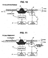
Figs. 10 and 11 show normal placement and misplacement, respectively, of the second embodiment of a high-density disk structured according to the present invention; -
Fig. 12 is a sectional view of the third embodiment of a high-density disk structured according to the present invention; and -
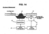
Figs. 13 and14 show normal placement and misplacement, respectively, of the third embodiment of a high-density disk structured according to the present invention. - In order that the invention may be fully understood, a preferred embodiment thereof will now be described with reference to the accompanying drawings.
-
Fig. 6 is a sectional view of the first preferred embodiment of a high-density disk structured according to the present invention. The embodiment of a high-density disk, for example, a HD-DVD according to the present invention has same dimension as a conventional HD-DVD depicted inFig. 3 , namely, 1.2mm in thickness and 120mm in diameter, a center hole of 15mm diameter and a clamping zone (or clamping area) of 44mm diameter encircling the center hole. In addition, when the present HD-DVD 20 ofFig. 6 is normally placed into a disk device, its recording layer, which contains pit patterns, would be approximately 0.1mm from the objective lens of an optical pickup as mentioned before. - However, the present HD-
DVD 20 inFig. 6 has a clamping zone structured such that the thickness (P1 and P2) of each side, P1 and P2, are different, namely and preferably P1 is greater than P2. P1 and P2 are created by bisecting the clamping zone with an imaginary longitudinal center plane "c." In order for both sides to have different thicknesses, the opposite side of the recording side, which is the recording layer, protrudes above the disk's upper surface, indicated by D1 inFig. 6 . Because it is not necessary for the entire clamping zone to have a different thickness, the clamping zone may have partial regions that are protruding or raised with respect to the recording or reading area of the disk. - The height D1 preferably ranges from about 0.1mm to 0.6mm and guarantees a marginal gap between the present disk and the objective lens for preventing a collision between the objective lens of an optical pickup even though the objective lens moves upward to the maximum movable distance on the condition that the present high-density disk has been placed upside down. Alternatively, other suitable height D1 may also be used without deviating from the present invention.
- If the
disk 20 structured as above is placed normally on a spindle orturntable 11 equipped in a disk device as shown inFig. 7 , the non-protruding side of the clamping zone of thepresent disk 20 is in contact with theturntable 11. Consequently, thedisk 20 is normally clamped the same as a conventional disk. - After successful clamping of the high-
density disk 20, a conventional servo-controlling operation, characterized by the operation of thespindle motor 12, themotor driving unit 13 and theservo controller 15, is conducted to rotate the right-clampeddisk 20 at a constant and high speed. Subsequently, a focusing-servo operation is conducted to focus a laser beam exactly onto a recording layer by moving the objective lens OL of theoptical pickup 14 up and down within the operating distance OD. Once the laser beam is exactly focused, reproduction (or recording) of the high-density pit patterns begins. - However, if the
present disk 20 is placed upside down on theturntable 11 as shown inFig. 8 , the protruding side of the clamping zone of thepresent disk 20 is in contact with theturntable 11. Consequently, the surface of thedisk 20 is raised by the height D1 over normal placement, which ranges from about 0.1mm to 0.6mm. In other words, the separation distance between the objective lens and thedisk 20 has increased due to the added thickness of the clamping zone. - Therefore, although the objective lens OL of the
optical pickup 14 moves up to the maximum distance to acquire the exact focus while themisplaced disk 20 is rotating at a high speed, the objective lens OL will not collide with the surface of themisplaced disk 20, due to the marginal gap D1 created by the protruding side of the clamping zone. Furthermore, because the recording layer, and the high-density pit patterns contained within, is also further apart from the objective lens OL than in normal placement, the focusing operation will fail. As a result, the misplacement of the disk would be judged as "no disk." Because a judgment of "no disk" ceases the focusing operation, a collision between the objective lens OL and thedisk 20 is avoided. -
Fig. 9 is a sectional view of the second preferred embodiment of a high-density disk structured according to the present invention. The second embodiment of a high-density disk 21 according to the present invention has a clamping zone structured such that the thickness of each side, P1 and P2, which are created by bisecting the clamping zone with an imaginary longitudinal center plane "c," are different. Namely, P1 is greater than P2, where both P1 and P2 are both greater than one-half of the whole thickness of thedisk 21 as shown inFig. 9 . The side opposite to the recording side protrudes from disk surface a greater distance than of the recording side. As shown inFig. 9 , the height D1, which ranges approximately from 0.1mm to 0.6mm, is greater than D2, which is located on the recording side. - The protruding height D2 of the recording side is preferably determined to be within a range that ensures a successful focus of the pit patterns within the recording layer by the objective lens OL as it moves up and down within the operating distance OD on the condition that the
disk 21 has been normally placed. - Therefore, if the high-
density disk 21 structured as above is placed normally on theturntable 11, the recording layer of thedisk 21 is further apart from the objective lens OL by the small protruding height D2 than that of a conventional disk. However, because the distance D2 is within a range ensuring successful focus as described above, it is possible to focus a light beam on the recording layer so that reproduction (or recording) of the high-density pit patterns can be conducted. - If the high-
density disk 21 is placed upside down on theturntable 11 as shown inFig. 11 , the surface containing the protruding side of the clamping zone that measures in height D1 is situated higher by the same height D1, similar to the situation depicted inFig. 8 . Consequently, the objective lens OL of theoptical pickup 14 can move up to the maximum distance to acquire an exact focus while themisplaced disk 21 is rotating at a high speed without colliding with the surface of themisplaced disk 21. Also, because the recording layer is further apart from the objective lens OL by the height D1, the focusing operation will fail, resulting in that the disk misplacement would be judged as "no disk." Because judgment of 'no disk' ceases all focusing operations, a collision between the objective lens OL and thedisk 21 is avoided. -
Fig. 12 is a sectional view of the third preferred embodiment of a high-density disk structured according to the present invention. The third embodiment of a high-density disk 22 according to the present invention has a clamping zone structured such that the thickness of each side, P1 and P2, which are created by bisecting the high-density disk 22 with an imaginary longitudinal center plane "c." In this case, P1 is greater than P2 and P1 is thicker than one-half of the whole thickness of thedisk 22 but P2 is thinner than one-half of the whole thickness of thedisk 22. The side opposite to the recording side protrudes from disk surface by the height D1, which ranges from approximately 0.1mm to 0.6mm, whereas the clamping zone on the recording side is indented by a height less than D1. - Therefore, if the high-
density disk 22 structured as above is placed normally on theturntable 11, the indented side of the clamping zone, which is in contact with a holder of theturntable 11, allows the recording layer of thedisk 22 to be appropriately apart from theoptical pickup 14. However, the distance between the recording layer and the objective lens OL for this embodiment is longer within the acceptable range for a conventional disk. - In this situation, an exact focus on the recording layer is acquired through moving the objective lens OL up and down within the operating distance OD, which can then result in the reproduction (or recording) of high-density pit patterns.
- If the
present disk 22 is placed upside down on theturntable 11 as shown inFig. 14 , the surface of thedisk 22 is raised by a height D1, which ranges from 0.1mm to 0.6mm. Therefore, although the objective lens OL of theoptical pickup 14 can move up to the maximum distance to acquire an exact focus on the recording layer, the objective lens OL will not collide with the surface of themisplaced disk 22. As described above, the misplacement would result in a reading of "no disk," which would cease the focusing operation and avoiding a collision between the objective lens OL and thedisk 22. - In addition, the protrusion and/or indentation of the claming zone may be shaped variously other than the aforementioned embodiments, for example, a clamping zone may be protruded or indented partially.
- The invention may be applicable to a rewritable high-density disk as well as a read-only high-density disk without departing from the sprit or essential characteristics thereof. Alternatively, the present invention may also be applied to any other rewritable or read-only type disk medium. The present embodiments are therefore to be considered in all respects as illustrative and not restrictive, the scope of the invention being indicated by the appended claims rather than by the foregoing description.
Claims (9)
- An optical disk (20, 21, 22) for storing data havingfirst and second surfaces, the second surface being an entrance surface with respect to a recording or reproducing light beam and being parallel to the first surface;a clamping area including first and second clamping surfaces;a first side having the first surface and the first clamping surface;a second side having the second surface and the second clamping surface;a center plane (c) being located in the middle between the first surface and the second surface;a center hole having a predetermined diameter; anda recording layer being located between the center plane (c) and the second surface, characterized in thatthe clamping area has a protruding portion on the first clamping surface,
wherein the clamping area at the protruding portion has first and second thickness (P1, P2) measured from the center plane of the disk (20, 21, 22), the first thickness (P1) measured in a direction extending from the center plane (c) of the disk (20, 21, 22) toward the first clamping surface of the clamping area and the second thickness (P2) measured in a direction toward the second clamping surface, wherein the first thickness (P1) is greater than the second thickness (P2) and wherein the recording layer is located at about 0.1mm from the second surface. - The optical disk (20, 21, 22) of claim 1, wherein a difference between the first and the second thicknesses (P1, P2) is approximately 0.1mm to 0.6mm.
- The optical disk (20) of one of the preceding claims, wherein:the second clamping surface is located concentrically within the second side and is level with the second surface of the second side; andthe first clamping surface is located concentrically within the first side and protrudes from the first surface of the first sides.
- The optical disk (21) of one of claims 1 to 2, wherein:the first clamping surface is located concentrically within the first side and protrudes from the first surface of the first side; andthe second clamping surface is located concentrically within the second side and protrudes from the second surface of the second side.
- The optical disk (21) of claim 4, wherein the first side clamping zone protrudes from the first surface of the first side a distance (D1) greater than the distance (D2) the second side clamping zone protrudes from the second surface of the second side.
- The optical disc (22) of one of claims 1 to 2, comprising:the second clamping surface is located concentrically within the second sided and is indented from the second surface of the second side; andthe first clamping surface is located concentrically within the first side and protrudes from the first surface of the first side.
- The optical disk (21, 22) of one of claims 4 to 6, wherein the first side clamping zone protrudes from the first surface of the first side a distance (D1) of about 0.1mm to 0.6mm.
- The optical disk (22) of one of claims 6 or 7, wherein the second side clamping zone is indented from the second surface of the second side a distance (D1) of about 0.1mm to 0.6mm.
- Recording medium comprising an optical disk (20, 21, 22) according to one of the preceding claims.
Priority Applications (1)
| Application Number | Priority Date | Filing Date | Title |
|---|---|---|---|
| EP05013739A EP1605451B1 (en) | 2001-05-14 | 2002-03-09 | High-density disk recording medium having a protruding side on a clamping zone |
Applications Claiming Priority (2)
| Application Number | Priority Date | Filing Date | Title |
|---|---|---|---|
| KR10-2001-0026250A KR100378086B1 (en) | 2001-05-14 | 2001-05-14 | High density optical disc having a difference hight of upper and lower surface in clamping area |
| KR2001026250 | 2001-05-14 |
Related Child Applications (1)
| Application Number | Title | Priority Date | Filing Date |
|---|---|---|---|
| EP05013739A Division EP1605451B1 (en) | 2001-05-14 | 2002-03-09 | High-density disk recording medium having a protruding side on a clamping zone |
Publications (3)
| Publication Number | Publication Date |
|---|---|
| EP1258872A2 EP1258872A2 (en) | 2002-11-20 |
| EP1258872A3 EP1258872A3 (en) | 2004-03-24 |
| EP1258872B1 true EP1258872B1 (en) | 2009-10-14 |
Family
ID=19709456
Family Applications (2)
| Application Number | Title | Priority Date | Filing Date |
|---|---|---|---|
| EP05013739A Expired - Lifetime EP1605451B1 (en) | 2001-05-14 | 2002-03-09 | High-density disk recording medium having a protruding side on a clamping zone |
| EP02005461A Expired - Lifetime EP1258872B1 (en) | 2001-05-14 | 2002-03-09 | High-density disk having a protruding portion on a clamping zone |
Family Applications Before (1)
| Application Number | Title | Priority Date | Filing Date |
|---|---|---|---|
| EP05013739A Expired - Lifetime EP1605451B1 (en) | 2001-05-14 | 2002-03-09 | High-density disk recording medium having a protruding side on a clamping zone |
Country Status (10)
| Country | Link |
|---|---|
| US (2) | US7012880B2 (en) |
| EP (2) | EP1605451B1 (en) |
| JP (1) | JP4094877B2 (en) |
| KR (1) | KR100378086B1 (en) |
| CN (3) | CN100372007C (en) |
| AT (2) | ATE445898T1 (en) |
| DE (2) | DE60231924D1 (en) |
| ES (2) | ES2332036T3 (en) |
| HK (1) | HK1100193A1 (en) |
| PT (1) | PT1258872E (en) |
Families Citing this family (17)
| Publication number | Priority date | Publication date | Assignee | Title |
|---|---|---|---|---|
| KR100378086B1 (en) * | 2001-05-14 | 2003-03-29 | 엘지전자 주식회사 | High density optical disc having a difference hight of upper and lower surface in clamping area |
| US6667953B2 (en) * | 2001-12-21 | 2003-12-23 | Seth Matson | Optical disk protector and method of use |
| US7617507B2 (en) * | 2003-06-03 | 2009-11-10 | Lg Electronics Inc. | High-density recording medium and recording and/or reproducing device therefor |
| KR100944992B1 (en) * | 2003-06-03 | 2010-03-05 | 엘지전자 주식회사 | High density optical disc having a difference thickness between information area and clamping area, and optical disc device therof |
| KR100987437B1 (en) | 2003-08-14 | 2010-10-13 | 엘지전자 주식회사 | Recording medium,recording method and recording apparatus |
| CN100449623C (en) * | 2003-10-31 | 2009-01-07 | 巨擘科技股份有限公司 | Optical disk base board, opticaldisk and its manufacturing method |
| CN100444263C (en) * | 2004-04-06 | 2008-12-17 | 建兴电子科技股份有限公司 | Optical driver with detecting inversing function and method thereof |
| KR101074737B1 (en) | 2005-04-22 | 2011-10-19 | 주식회사 히타치엘지 데이터 스토리지 코리아 | Light Scribe Disc and method for focusing thereof |
| FR2887678B1 (en) * | 2005-06-28 | 2007-09-28 | Digital Valley | UNIVERSAL DIGITAL DISK |
| JP2007026507A (en) * | 2005-07-14 | 2007-02-01 | Matsushita Electric Ind Co Ltd | Optical pickup device |
| EP1923873A1 (en) * | 2006-11-15 | 2008-05-21 | ODS Technology GmbH | EcoDisc |
| DE06023769T1 (en) * | 2006-11-15 | 2008-10-23 | Ods Technology Gmbh | EcoDisc |
| EP2117003A3 (en) * | 2006-11-20 | 2010-01-13 | EcoDisc Technology AG | Smart video card |
| WO2008108676A1 (en) * | 2007-03-06 | 2008-09-12 | Andrei Vladimirovich Tropillo | Disc information carrier |
| CN101807414A (en) * | 2010-04-21 | 2010-08-18 | 江苏新广联科技股份有限公司 | Optical disk and method for bonding and thickening clamping area of thin optical disk |
| EP3699218A1 (en) * | 2019-02-22 | 2020-08-26 | Covestro Deutschland AG | Novel two-component coating systems containing polyaspartic acid ester |
| CN113412295B (en) * | 2019-02-22 | 2023-08-25 | 科思创知识产权两合公司 | Novel two-component varnish system comprising polyaspartic esters |
Family Cites Families (34)
| Publication number | Priority date | Publication date | Assignee | Title |
|---|---|---|---|---|
| JPS59116942A (en) * | 1982-12-23 | 1984-07-06 | Olympus Optical Co Ltd | Auto-focusing device |
| JPH0636253B2 (en) | 1983-08-18 | 1994-05-11 | シャープ株式会社 | Optical memory disc |
| US5448547A (en) * | 1987-12-01 | 1995-09-05 | Mitsui Petrochemical Industries, Ltd. | Information recording discs |
| JPH0731422Y2 (en) * | 1987-12-01 | 1995-07-19 | 三井石油化学工業株式会社 | optical disk |
| US5235581A (en) * | 1990-08-09 | 1993-08-10 | Matsushita Electric Industrial Co., Ltd. | Optical recording/reproducing apparatus for optical disks with various disk substrate thicknesses |
| JPH05225609A (en) | 1992-02-06 | 1993-09-03 | Tdk Corp | Optical disk base plate and optical disk |
| JP3377048B2 (en) * | 1992-04-24 | 2003-02-17 | パイオニア株式会社 | Playback apparatus and playback method for write-once optical disc |
| JPH0814929B2 (en) * | 1992-12-28 | 1996-02-14 | ティアック株式会社 | Optical disk drive |
| JP2973155B2 (en) * | 1993-10-29 | 1999-11-08 | 株式会社名機製作所 | Disk substrate and molding die used for molding the disk substrate |
| KR100200838B1 (en) * | 1995-01-24 | 1999-06-15 | 윤종용 | Multilayered disk |
| DE19631319A1 (en) | 1995-08-15 | 1997-02-20 | Minnesota Mining & Mfg | Optical disc for digital data recording |
| JPH09204686A (en) | 1996-01-29 | 1997-08-05 | Sony Disc Technol:Kk | Optical disk and production thereof |
| JPH10188508A (en) | 1996-12-25 | 1998-07-21 | Sony Corp | Optical disc |
| JPH10283683A (en) | 1997-02-05 | 1998-10-23 | Sony Corp | Optical recording medium and its manufacture |
| JPH10269621A (en) * | 1997-03-25 | 1998-10-09 | Sony Corp | Optical disk substrate and optical disk using the substrate |
| JPH10269620A (en) | 1997-03-26 | 1998-10-09 | Sanyo Electric Co Ltd | Optical disk |
| JP3177485B2 (en) * | 1997-08-05 | 2001-06-18 | 三洋電機株式会社 | optical disk |
| CN1224216A (en) * | 1997-11-24 | 1999-07-28 | 三星电子株式会社 | Method and apparatus for discriminating rewritable discs |
| JP3988236B2 (en) * | 1998-02-13 | 2007-10-10 | ヤマハ株式会社 | optical disk |
| US6214430B1 (en) * | 1998-04-10 | 2001-04-10 | Lg Electronics Inc. | Disc recording medium and method of fabricating the same |
| AU1078800A (en) | 1998-11-06 | 2000-05-29 | Hitachi Maxell, Ltd. | Optical disk, disk substrate, and drive |
| JP2000251324A (en) | 1999-02-26 | 2000-09-14 | Sony Corp | Optical recording medium |
| JP4158262B2 (en) * | 1999-02-26 | 2008-10-01 | ソニー株式会社 | Information recording / reproducing apparatus and method, and recording medium |
| JP2000322765A (en) * | 1999-05-12 | 2000-11-24 | Sharp Corp | Optical recording medium |
| JP2001006210A (en) * | 1999-06-22 | 2001-01-12 | Sony Corp | Optical recording medium and disk cartridge |
| JP2001006264A (en) * | 1999-06-22 | 2001-01-12 | Matsushita Electric Ind Co Ltd | Optical disk recording and reproducing device |
| JP4215923B2 (en) | 2000-02-02 | 2009-01-28 | 株式会社ソニー・ディスクアンドデジタルソリューションズ | Optical disc and mold for injection compression molding thereof |
| US6584067B2 (en) | 2000-03-03 | 2003-06-24 | Tosoh Corporation | Optical recording medium having a recording/reproducing area with a shaped region |
| EP1152407A3 (en) | 2000-04-25 | 2006-10-25 | Matsushita Electric Industrial Co., Ltd. | Optical disk, method for producing the same, and apparatus for producing the same |
| JP2002170279A (en) | 2000-11-30 | 2002-06-14 | Sony Corp | Optical recording medium, its manufacturing method and injection molding machine |
| KR100419211B1 (en) | 2000-12-20 | 2004-02-19 | 삼성전자주식회사 | Disk type recording medium |
| KR100378086B1 (en) | 2001-05-14 | 2003-03-29 | 엘지전자 주식회사 | High density optical disc having a difference hight of upper and lower surface in clamping area |
| US6865745B2 (en) | 2001-08-10 | 2005-03-08 | Wea Manufacturing, Inc. | Methods and apparatus for reducing the shrinkage of an optical disc's clamp area and the resulting optical disc |
| KR100499479B1 (en) | 2002-09-10 | 2005-07-05 | 엘지전자 주식회사 | Digital Versatile Disc of high density |
-
2001
- 2001-05-14 KR KR10-2001-0026250A patent/KR100378086B1/en active IP Right Grant
-
2002
- 2002-03-05 US US10/097,547 patent/US7012880B2/en not_active Expired - Lifetime
- 2002-03-09 DE DE60231924T patent/DE60231924D1/en not_active Expired - Lifetime
- 2002-03-09 EP EP05013739A patent/EP1605451B1/en not_active Expired - Lifetime
- 2002-03-09 ES ES02005461T patent/ES2332036T3/en not_active Expired - Lifetime
- 2002-03-09 AT AT02005461T patent/ATE445898T1/en not_active IP Right Cessation
- 2002-03-09 PT PT02005461T patent/PT1258872E/en unknown
- 2002-03-09 AT AT05013739T patent/ATE428172T1/en not_active IP Right Cessation
- 2002-03-09 ES ES05013739T patent/ES2321950T3/en not_active Expired - Lifetime
- 2002-03-09 EP EP02005461A patent/EP1258872B1/en not_active Expired - Lifetime
- 2002-03-09 DE DE60233995T patent/DE60233995D1/en not_active Expired - Lifetime
- 2002-04-02 JP JP2002099720A patent/JP4094877B2/en not_active Expired - Fee Related
- 2002-05-14 CN CNB2004100901409A patent/CN100372007C/en not_active Expired - Lifetime
- 2002-05-14 CN CNB021191832A patent/CN1266691C/en not_active Expired - Fee Related
- 2002-05-14 CN CN2006100923604A patent/CN1870154B/en not_active Expired - Fee Related
-
2004
- 2004-07-16 US US10/892,879 patent/US7515524B2/en not_active Expired - Fee Related
-
2007
- 2007-05-29 HK HK07105729.0A patent/HK1100193A1/en not_active IP Right Cessation
Non-Patent Citations (1)
| Title |
|---|
| NARAHARA ET AL: "Optical Disc System for Digital Video Recording", JAPANESE JOURNAL OF APPLIED PHYSICS, vol. 39, no. 2B, February 2000 (2000-02-01), pages 912 - 919, XP001005912 * |
Also Published As
| Publication number | Publication date |
|---|---|
| EP1605451A1 (en) | 2005-12-14 |
| ES2332036T3 (en) | 2010-01-25 |
| CN1266691C (en) | 2006-07-26 |
| US20040257941A1 (en) | 2004-12-23 |
| EP1605451B1 (en) | 2009-04-08 |
| DE60231924D1 (en) | 2009-05-20 |
| CN1870154A (en) | 2006-11-29 |
| ATE428172T1 (en) | 2009-04-15 |
| CN1870154B (en) | 2012-05-23 |
| CN1385848A (en) | 2002-12-18 |
| HK1100193A1 (en) | 2007-09-07 |
| CN100372007C (en) | 2008-02-27 |
| DE60233995D1 (en) | 2009-11-26 |
| EP1258872A2 (en) | 2002-11-20 |
| KR100378086B1 (en) | 2003-03-29 |
| JP2002342978A (en) | 2002-11-29 |
| US7012880B2 (en) | 2006-03-14 |
| US7515524B2 (en) | 2009-04-07 |
| PT1258872E (en) | 2009-10-22 |
| EP1258872A3 (en) | 2004-03-24 |
| US20020167892A1 (en) | 2002-11-14 |
| ATE445898T1 (en) | 2009-10-15 |
| JP4094877B2 (en) | 2008-06-04 |
| ES2321950T3 (en) | 2009-06-15 |
| CN1612244A (en) | 2005-05-04 |
| KR20020087222A (en) | 2002-11-22 |
Similar Documents
| Publication | Publication Date | Title |
|---|---|---|
| EP1258872B1 (en) | High-density disk having a protruding portion on a clamping zone | |
| US8199616B2 (en) | Assembly method of optical pickup and optical pickup apparatus | |
| EP0810598A2 (en) | Optical disk apparatus | |
| JP4141622B2 (en) | Pickup device | |
| US7761887B2 (en) | Recording medium having a reflector to prevent traveling of beam to recording layer | |
| JP3291444B2 (en) | Optical pickup device | |
| JP2896110B2 (en) | Optical recording medium identification device | |
| KR100713833B1 (en) | Apparatus for detecting an error insert optical disc | |
| JP3575181B2 (en) | Recording and / or reproducing apparatus for optical recording medium and optical pickup used therein | |
| EP1488419B1 (en) | Servo-controlling method of an optical disk apparatus | |
| JPH1097755A (en) | Optical disk recording and reproducing device | |
| KR20040024014A (en) | High-density optical disc and method for driving them | |
| KR20030000899A (en) | High density optical disc and method for driving them | |
| KR100712775B1 (en) | High density optical disc and method for manufacturing them | |
| KR20020087668A (en) | High density optical disc and, apparatus for driving them | |
| JP2708024B2 (en) | Optical disc identification method | |
| KR20040104284A (en) | High density optical disc having a difference thickness between information area and clamping area, and optical disc device therof | |
| KR20100003348A (en) | High density optical disc having a difference thickness between information area and clamping area, and optical disc device therof | |
| KR20030000902A (en) | High density optical disc and apparatus for driving them | |
| JPH0567362A (en) | Magneto-optical recorder | |
| JPH09204729A (en) | Optical disk device | |
| JPH11175986A (en) | Optical disk recording/reproducing device | |
| KR20030069544A (en) | High density optical disk driver, optical recorder thereof | |
| KR20030001946A (en) | Apparatus and method for determining an error insert for optical disc | |
| KR20050088631A (en) | Method for discriminating thickness of high density-optical disk |
Legal Events
| Date | Code | Title | Description |
|---|---|---|---|
| PUAI | Public reference made under article 153(3) epc to a published international application that has entered the european phase |
Free format text: ORIGINAL CODE: 0009012 |
|
| AK | Designated contracting states |
Kind code of ref document: A2 Designated state(s): AT BE CH CY DE DK ES FI FR GB GR IE IT LI LU MC NL PT SE TR |
|
| AX | Request for extension of the european patent |
Free format text: AL;LT;LV;MK;RO;SI |
|
| PUAL | Search report despatched |
Free format text: ORIGINAL CODE: 0009013 |
|
| AK | Designated contracting states |
Kind code of ref document: A3 Designated state(s): AT BE CH CY DE DK ES FI FR GB GR IE IT LI LU MC NL PT SE TR |
|
| AX | Request for extension of the european patent |
Extension state: AL LT LV MK RO SI |
|
| 17P | Request for examination filed |
Effective date: 20040709 |
|
| 17Q | First examination report despatched |
Effective date: 20041027 |
|
| AKX | Designation fees paid |
Designated state(s): AT BE CH CY DE DK ES FI FR GB GR IE IT LI LU MC NL PT SE TR |
|
| GRAP | Despatch of communication of intention to grant a patent |
Free format text: ORIGINAL CODE: EPIDOSNIGR1 |
|
| GRAC | Information related to communication of intention to grant a patent modified |
Free format text: ORIGINAL CODE: EPIDOSCIGR1 |
|
| GRAC | Information related to communication of intention to grant a patent modified |
Free format text: ORIGINAL CODE: EPIDOSCIGR1 |
|
| GRAS | Grant fee paid |
Free format text: ORIGINAL CODE: EPIDOSNIGR3 |
|
| GRAA | (expected) grant |
Free format text: ORIGINAL CODE: 0009210 |
|
| AK | Designated contracting states |
Kind code of ref document: B1 Designated state(s): AT BE CH CY DE DK ES FI FR GB GR IE IT LI LU MC NL PT SE TR |
|
| REG | Reference to a national code |
Ref country code: GB Ref legal event code: FG4D |
|
| REG | Reference to a national code |
Ref country code: CH Ref legal event code: EP |
|
| REG | Reference to a national code |
Ref country code: PT Ref legal event code: SC4A Free format text: AVAILABILITY OF NATIONAL TRANSLATION Effective date: 20091016 |
|
| REG | Reference to a national code |
Ref country code: IE Ref legal event code: FG4D |
|
| REF | Corresponds to: |
Ref document number: 60233995 Country of ref document: DE Date of ref document: 20091126 Kind code of ref document: P |
|
| REG | Reference to a national code |
Ref country code: ES Ref legal event code: FG2A Ref document number: 2332036 Country of ref document: ES Kind code of ref document: T3 |
|
| PG25 | Lapsed in a contracting state [announced via postgrant information from national office to epo] |
Ref country code: SE Free format text: LAPSE BECAUSE OF FAILURE TO SUBMIT A TRANSLATION OF THE DESCRIPTION OR TO PAY THE FEE WITHIN THE PRESCRIBED TIME-LIMIT Effective date: 20091014 |
|
| PG25 | Lapsed in a contracting state [announced via postgrant information from national office to epo] |
Ref country code: BE Free format text: LAPSE BECAUSE OF FAILURE TO SUBMIT A TRANSLATION OF THE DESCRIPTION OR TO PAY THE FEE WITHIN THE PRESCRIBED TIME-LIMIT Effective date: 20091014 Ref country code: AT Free format text: LAPSE BECAUSE OF FAILURE TO SUBMIT A TRANSLATION OF THE DESCRIPTION OR TO PAY THE FEE WITHIN THE PRESCRIBED TIME-LIMIT Effective date: 20091014 |
|
| PG25 | Lapsed in a contracting state [announced via postgrant information from national office to epo] |
Ref country code: DK Free format text: LAPSE BECAUSE OF FAILURE TO SUBMIT A TRANSLATION OF THE DESCRIPTION OR TO PAY THE FEE WITHIN THE PRESCRIBED TIME-LIMIT Effective date: 20091014 |
|
| PLBE | No opposition filed within time limit |
Free format text: ORIGINAL CODE: 0009261 |
|
| STAA | Information on the status of an ep patent application or granted ep patent |
Free format text: STATUS: NO OPPOSITION FILED WITHIN TIME LIMIT |
|
| 26N | No opposition filed |
Effective date: 20100715 |
|
| PG25 | Lapsed in a contracting state [announced via postgrant information from national office to epo] |
Ref country code: GR Free format text: LAPSE BECAUSE OF FAILURE TO SUBMIT A TRANSLATION OF THE DESCRIPTION OR TO PAY THE FEE WITHIN THE PRESCRIBED TIME-LIMIT Effective date: 20100115 Ref country code: MC Free format text: LAPSE BECAUSE OF NON-PAYMENT OF DUE FEES Effective date: 20100331 |
|
| REG | Reference to a national code |
Ref country code: CH Ref legal event code: PL |
|
| PG25 | Lapsed in a contracting state [announced via postgrant information from national office to epo] |
Ref country code: IE Free format text: LAPSE BECAUSE OF NON-PAYMENT OF DUE FEES Effective date: 20100309 |
|
| PG25 | Lapsed in a contracting state [announced via postgrant information from national office to epo] |
Ref country code: LI Free format text: LAPSE BECAUSE OF NON-PAYMENT OF DUE FEES Effective date: 20100331 Ref country code: CH Free format text: LAPSE BECAUSE OF NON-PAYMENT OF DUE FEES Effective date: 20100331 |
|
| PG25 | Lapsed in a contracting state [announced via postgrant information from national office to epo] |
Ref country code: CY Free format text: LAPSE BECAUSE OF FAILURE TO SUBMIT A TRANSLATION OF THE DESCRIPTION OR TO PAY THE FEE WITHIN THE PRESCRIBED TIME-LIMIT Effective date: 20091014 |
|
| PG25 | Lapsed in a contracting state [announced via postgrant information from national office to epo] |
Ref country code: LU Free format text: LAPSE BECAUSE OF NON-PAYMENT OF DUE FEES Effective date: 20100309 |
|
| PGFP | Annual fee paid to national office [announced via postgrant information from national office to epo] |
Ref country code: DE Payment date: 20150211 Year of fee payment: 14 |
|
| REG | Reference to a national code |
Ref country code: FR Ref legal event code: PLFP Year of fee payment: 15 |
|
| PGFP | Annual fee paid to national office [announced via postgrant information from national office to epo] |
Ref country code: ES Payment date: 20160222 Year of fee payment: 15 Ref country code: TR Payment date: 20160304 Year of fee payment: 15 |
|
| PGFP | Annual fee paid to national office [announced via postgrant information from national office to epo] |
Ref country code: NL Payment date: 20160216 Year of fee payment: 15 Ref country code: GB Payment date: 20160216 Year of fee payment: 15 Ref country code: FR Payment date: 20160217 Year of fee payment: 15 Ref country code: FI Payment date: 20160212 Year of fee payment: 15 Ref country code: PT Payment date: 20160229 Year of fee payment: 15 |
|
| PGFP | Annual fee paid to national office [announced via postgrant information from national office to epo] |
Ref country code: IT Payment date: 20160318 Year of fee payment: 15 |
|
| REG | Reference to a national code |
Ref country code: DE Ref legal event code: R119 Ref document number: 60233995 Country of ref document: DE |
|
| PG25 | Lapsed in a contracting state [announced via postgrant information from national office to epo] |
Ref country code: DE Free format text: LAPSE BECAUSE OF NON-PAYMENT OF DUE FEES Effective date: 20161001 |
|
| PG25 | Lapsed in a contracting state [announced via postgrant information from national office to epo] |
Ref country code: FI Free format text: LAPSE BECAUSE OF NON-PAYMENT OF DUE FEES Effective date: 20170309 |
|
| REG | Reference to a national code |
Ref country code: NL Ref legal event code: MM Effective date: 20170401 |
|
| GBPC | Gb: european patent ceased through non-payment of renewal fee |
Effective date: 20170309 |
|
| PG25 | Lapsed in a contracting state [announced via postgrant information from national office to epo] |
Ref country code: PT Free format text: LAPSE BECAUSE OF NON-PAYMENT OF DUE FEES Effective date: 20170911 |
|
| REG | Reference to a national code |
Ref country code: FR Ref legal event code: ST Effective date: 20171130 |
|
| PG25 | Lapsed in a contracting state [announced via postgrant information from national office to epo] |
Ref country code: FR Free format text: LAPSE BECAUSE OF NON-PAYMENT OF DUE FEES Effective date: 20170331 Ref country code: NL Free format text: LAPSE BECAUSE OF NON-PAYMENT OF DUE FEES Effective date: 20170401 |
|
| PG25 | Lapsed in a contracting state [announced via postgrant information from national office to epo] |
Ref country code: IT Free format text: LAPSE BECAUSE OF NON-PAYMENT OF DUE FEES Effective date: 20170309 Ref country code: GB Free format text: LAPSE BECAUSE OF NON-PAYMENT OF DUE FEES Effective date: 20170309 |
|
| REG | Reference to a national code |
Ref country code: ES Ref legal event code: FD2A Effective date: 20180629 |
|
| PG25 | Lapsed in a contracting state [announced via postgrant information from national office to epo] |
Ref country code: ES Free format text: LAPSE BECAUSE OF NON-PAYMENT OF DUE FEES Effective date: 20170310 |
|
| PG25 | Lapsed in a contracting state [announced via postgrant information from national office to epo] |
Ref country code: TR Free format text: LAPSE BECAUSE OF NON-PAYMENT OF DUE FEES Effective date: 20170309 |