EP1591675B1 - Verbindungsanordnung mit einem Kunststoff-Trägerteil und einem Kunststoff-Gewindeelement - Google Patents
Verbindungsanordnung mit einem Kunststoff-Trägerteil und einem Kunststoff-Gewindeelement Download PDFInfo
- Publication number
- EP1591675B1 EP1591675B1 EP05009142A EP05009142A EP1591675B1 EP 1591675 B1 EP1591675 B1 EP 1591675B1 EP 05009142 A EP05009142 A EP 05009142A EP 05009142 A EP05009142 A EP 05009142A EP 1591675 B1 EP1591675 B1 EP 1591675B1
- Authority
- EP
- European Patent Office
- Prior art keywords
- thread
- threaded
- joining assembly
- threaded element
- support member
- Prior art date
- Legal status (The legal status is an assumption and is not a legal conclusion. Google has not performed a legal analysis and makes no representation as to the accuracy of the status listed.)
- Expired - Lifetime
Links
Images


Classifications
-
- F—MECHANICAL ENGINEERING; LIGHTING; HEATING; WEAPONS; BLASTING
- F16—ENGINEERING ELEMENTS AND UNITS; GENERAL MEASURES FOR PRODUCING AND MAINTAINING EFFECTIVE FUNCTIONING OF MACHINES OR INSTALLATIONS; THERMAL INSULATION IN GENERAL
- F16B—DEVICES FOR FASTENING OR SECURING CONSTRUCTIONAL ELEMENTS OR MACHINE PARTS TOGETHER, e.g. NAILS, BOLTS, CIRCLIPS, CLAMPS, CLIPS OR WEDGES; JOINTS OR JOINTING
- F16B35/00—Screw-bolts; Stay-bolts; Screw-threaded studs; Screws; Set screws
- F16B35/005—Set screws; Locking means therefor
-
- F—MECHANICAL ENGINEERING; LIGHTING; HEATING; WEAPONS; BLASTING
- F16—ENGINEERING ELEMENTS AND UNITS; GENERAL MEASURES FOR PRODUCING AND MAINTAINING EFFECTIVE FUNCTIONING OF MACHINES OR INSTALLATIONS; THERMAL INSULATION IN GENERAL
- F16B—DEVICES FOR FASTENING OR SECURING CONSTRUCTIONAL ELEMENTS OR MACHINE PARTS TOGETHER, e.g. NAILS, BOLTS, CIRCLIPS, CLAMPS, CLIPS OR WEDGES; JOINTS OR JOINTING
- F16B25/00—Screws that cut thread in the body into which they are screwed, e.g. wood screws
- F16B25/10—Screws performing an additional function to thread-forming, e.g. drill screws or self-piercing screws
-
- F—MECHANICAL ENGINEERING; LIGHTING; HEATING; WEAPONS; BLASTING
- F16—ENGINEERING ELEMENTS AND UNITS; GENERAL MEASURES FOR PRODUCING AND MAINTAINING EFFECTIVE FUNCTIONING OF MACHINES OR INSTALLATIONS; THERMAL INSULATION IN GENERAL
- F16B—DEVICES FOR FASTENING OR SECURING CONSTRUCTIONAL ELEMENTS OR MACHINE PARTS TOGETHER, e.g. NAILS, BOLTS, CIRCLIPS, CLAMPS, CLIPS OR WEDGES; JOINTS OR JOINTING
- F16B25/00—Screws that cut thread in the body into which they are screwed, e.g. wood screws
- F16B25/001—Screws that cut thread in the body into which they are screwed, e.g. wood screws characterised by the material of the body into which the screw is screwed
- F16B25/0015—Screws that cut thread in the body into which they are screwed, e.g. wood screws characterised by the material of the body into which the screw is screwed the material being a soft organic material, e.g. wood or plastic
-
- F—MECHANICAL ENGINEERING; LIGHTING; HEATING; WEAPONS; BLASTING
- F16—ENGINEERING ELEMENTS AND UNITS; GENERAL MEASURES FOR PRODUCING AND MAINTAINING EFFECTIVE FUNCTIONING OF MACHINES OR INSTALLATIONS; THERMAL INSULATION IN GENERAL
- F16B—DEVICES FOR FASTENING OR SECURING CONSTRUCTIONAL ELEMENTS OR MACHINE PARTS TOGETHER, e.g. NAILS, BOLTS, CIRCLIPS, CLAMPS, CLIPS OR WEDGES; JOINTS OR JOINTING
- F16B25/00—Screws that cut thread in the body into which they are screwed, e.g. wood screws
- F16B25/0036—Screws that cut thread in the body into which they are screwed, e.g. wood screws characterised by geometric details of the screw
- F16B25/0042—Screws that cut thread in the body into which they are screwed, e.g. wood screws characterised by geometric details of the screw characterised by the geometry of the thread, the thread being a ridge wrapped around the shaft of the screw
- F16B25/0047—Screws that cut thread in the body into which they are screwed, e.g. wood screws characterised by geometric details of the screw characterised by the geometry of the thread, the thread being a ridge wrapped around the shaft of the screw the ridge being characterised by its cross-section in the plane of the shaft axis
-
- F—MECHANICAL ENGINEERING; LIGHTING; HEATING; WEAPONS; BLASTING
- F16—ENGINEERING ELEMENTS AND UNITS; GENERAL MEASURES FOR PRODUCING AND MAINTAINING EFFECTIVE FUNCTIONING OF MACHINES OR INSTALLATIONS; THERMAL INSULATION IN GENERAL
- F16B—DEVICES FOR FASTENING OR SECURING CONSTRUCTIONAL ELEMENTS OR MACHINE PARTS TOGETHER, e.g. NAILS, BOLTS, CIRCLIPS, CLAMPS, CLIPS OR WEDGES; JOINTS OR JOINTING
- F16B25/00—Screws that cut thread in the body into which they are screwed, e.g. wood screws
- F16B25/0036—Screws that cut thread in the body into which they are screwed, e.g. wood screws characterised by geometric details of the screw
- F16B25/0042—Screws that cut thread in the body into which they are screwed, e.g. wood screws characterised by geometric details of the screw characterised by the geometry of the thread, the thread being a ridge wrapped around the shaft of the screw
- F16B25/0052—Screws that cut thread in the body into which they are screwed, e.g. wood screws characterised by geometric details of the screw characterised by the geometry of the thread, the thread being a ridge wrapped around the shaft of the screw the ridge having indentations, notches or the like in order to improve the cutting behaviour
-
- F—MECHANICAL ENGINEERING; LIGHTING; HEATING; WEAPONS; BLASTING
- F16—ENGINEERING ELEMENTS AND UNITS; GENERAL MEASURES FOR PRODUCING AND MAINTAINING EFFECTIVE FUNCTIONING OF MACHINES OR INSTALLATIONS; THERMAL INSULATION IN GENERAL
- F16B—DEVICES FOR FASTENING OR SECURING CONSTRUCTIONAL ELEMENTS OR MACHINE PARTS TOGETHER, e.g. NAILS, BOLTS, CIRCLIPS, CLAMPS, CLIPS OR WEDGES; JOINTS OR JOINTING
- F16B33/00—Features common to bolt and nut
- F16B33/006—Non-metallic fasteners using screw-thread
-
- F—MECHANICAL ENGINEERING; LIGHTING; HEATING; WEAPONS; BLASTING
- F16—ENGINEERING ELEMENTS AND UNITS; GENERAL MEASURES FOR PRODUCING AND MAINTAINING EFFECTIVE FUNCTIONING OF MACHINES OR INSTALLATIONS; THERMAL INSULATION IN GENERAL
- F16B—DEVICES FOR FASTENING OR SECURING CONSTRUCTIONAL ELEMENTS OR MACHINE PARTS TOGETHER, e.g. NAILS, BOLTS, CIRCLIPS, CLAMPS, CLIPS OR WEDGES; JOINTS OR JOINTING
- F16B33/00—Features common to bolt and nut
- F16B33/02—Shape of thread; Special thread-forms
-
- Y—GENERAL TAGGING OF NEW TECHNOLOGICAL DEVELOPMENTS; GENERAL TAGGING OF CROSS-SECTIONAL TECHNOLOGIES SPANNING OVER SEVERAL SECTIONS OF THE IPC; TECHNICAL SUBJECTS COVERED BY FORMER USPC CROSS-REFERENCE ART COLLECTIONS [XRACs] AND DIGESTS
- Y10—TECHNICAL SUBJECTS COVERED BY FORMER USPC
- Y10S—TECHNICAL SUBJECTS COVERED BY FORMER USPC CROSS-REFERENCE ART COLLECTIONS [XRACs] AND DIGESTS
- Y10S411/00—Expanded, threaded, driven, headed, tool-deformed, or locked-threaded fastener
- Y10S411/904—Fastener or fastener element composed of nonmetallic material
- Y10S411/908—Resinous material
Definitions
- the present invention relates to a connection arrangement with a carrier part made of plastic and a threaded element made of plastic, which is screwed into a receiving bore of the carrier part and has a core and an external thread which forms a counter-thread in the receiving bore when screwed into the smooth-walled receiving bore of the carrier part ( DE 203 07 622 U1).
- the invention further relates to a threaded element in the form of a screw or threaded bushing for such a connection arrangement.
- connection arrangements with a plastic carrier part and a plastic threaded element in the form of a screw or a threaded bushing with a "self-tapping" external thread are known, s. z.
- the threaded elements used here are usually equipped with a very special thread profile so that they can fulfill their self-tapping function.
- DE 42 27 272 A1 discloses a threaded element with a so-called round profile, in which the thread has an arcuate profile in an axial section, wherein the turns of the thread are separated in the axial direction by small gaps.
- a threaded bushing with an external thread is known, whose thread has an increasing in the screwing from a minimum value to a maximum value thread height to form the largest value of the thread height a paragraph that will serve as Austaxsperre.
- the thread is formed in this case as a pointed thread.
- a self-tapping plastic screw is known, are formed in the longitudinally extending grooves in each thread, two diametrically opposed cutting edges, which are effective in the screwing to screwing the screw into the receiving bore of the support member to the counter thread to cut.
- the present invention has for its object to provide a connection assembly of the type specified above, a threaded element in the form of a screw or a threaded bushing therefor and a tool and a method for producing such a connection arrangement, which optimizes the connection assembly and its threaded member with respect to Allow thread forming, strength, load capacity, dimensional stability and safety against unintentional release.
- the external thread of the threaded element has a very special thread profile, which is defined in claim 1, wherein specific embodiments of this profile in the claims 2 to 6 are defined.
- the external thread can be formed as a fine thread or as a multi-start thread.
- the external thread of the threaded element has a specially designed cutting geometry, which is defined in claim 9, wherein specific embodiments of the cutting geometry are defined in claims 10 to 14. Further details of the external thread of the threaded element will be apparent from the claims 15 to 17.
- the threaded element is expediently provided at its one end with a specially designed gate region, which is defined in claims 18 to 22.
- the threaded element is designed as a screw
- the transition region between the screw shaft and the screw head is formed in a special manner, as can be seen from claims 23 to 27.
- the threaded element can also be formed as a threaded bush, as is apparent from the claims 28 and 29.
- the invention relates in addition to the connection arrangement, the threaded element itself, which may be a screw or a threaded bushing (claim 32).
- Fig. 1 shows a connection assembly 1 with a support part 2 made of plastic and a threaded element in the form of a screw 4, also made of plastic.
- the connection assembly 1 is formed as a screw in which the screw 4 braces the carrier part 2 with a further component 3. If, however, the threaded element is designed as a threaded bushing 6 (FIGS. 7 to 12), then the connecting arrangement consists only of the threaded bushing and the carrier part 2.
- the screw 4 consists of a screw shaft with a solid core 8 and an external thread 10 with a single thread 11, a screw head 12, a transition region 14 between the screw shaft and the screw head 12, a drive means 16 and a Gating region 18 at the end facing away from the screw head of the core.
- Fig. 1 shows the arrangement on the left side before and on the right side after screwing the screw 4 in the receiving bore 20.
- the receiving bore 20 is smooth-walled before screwing the screw 4.
- the external thread 10 of the screw 4 is formed "self-tapping" or thread-forming, so that it forms a counter-thread 26 in the receiving bore 20 when screwing the screw 4 into the receiving bore 20, as will be explained in more detail below.
- the support member 2 has a counterbore 22, the diameter D 2 is slightly larger than the diameter D 1 of the receiving bore 20 and substantially corresponds to the outer diameter of the external thread 10.
- the component 3 has a through hole 24 whose diameter D 3 is slightly larger than the diameter D 1 and D 2 .
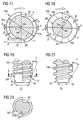
- the in Figs. 2 to 6 illustrated screws 4A and 4B differ from the screw 4 in Fig. 1 only in terms of the design of the screw head, which is provided in the case of the screws 4A and 4B as a multi-function head with an outer and inner drive means 16.
- the drive means can be formed in any manner.
- the outer drive means is formed as a hexagon with collar support, while the inner drive means is a hexalobular, but may also be for example a Phillips.
- the screws 4A and 4B in turn differ in terms of their thread profile, as will be explained in more detail below.
- the thread profile of the plastic screw or threaded bush according to the invention is designed so that it optimally forms the mating thread 26 when penetrating into the receiving bore 20 of the support part 2.
- the shaping of the counter thread 26 can be done by a cutting process or by a material deformation or by a combination of both processes.
- the present invention is based on the recognition that in support parts of a material that predominantly requires a cutting process for forming the counter thread, a slightly different thread profile of the plastic screw or threaded bushing than in support parts of a material that requires predominantly a material deformation for forming the counter thread , is appropriate.
- a slightly different thread profile of the plastic screw or threaded bushing than in support parts of a material that requires predominantly a material deformation for forming the counter thread is appropriate.
- two different embodiments A and B are shown in particular for hard, solid materials of the support part, in which for the penetration into the material of the support member predominantly a cutting operation is required
- the embodiment B is intended for materials of high elongation and impact strength, for forming the counter-thread predominantly one Require material deformation.
- the external threads 10A and 10B each have a thread 11 extending over several turns around the core 8A and 8B, respectively.
- the thread 11 has, seen in an axial section, a symmetrical profile formed by two rectilinear flanks 30 which are arranged symmetrically with respect to a radial line.
- the flanks 30 are at their flank tip in each case by a - preferably circular arc - rounded 31 connected to the radius R1.
- the core 8A or 8B has between the turns of the thread 11, a cylindrical outer surface 32, which are connected to the flanks 30 of the thread 11 each by a - preferably circular arc - - rounded 33.
- the axial distance between the turns of the thread 11 is selected so that the space between the turns of the thread 11 has a larger volume than the thread.
- the profile angle ⁇ , the flanks 30 of the thread 11 include each other, is chosen relatively small for reasons to be explained.
- the profile angle ⁇ is suitably in the range between 30 ° and 50 ° and is preferably about 40 °.
- P is the pitch
- Z the profile height
- R1 the radius of curvature of the curves 31 at the flank tip
- R2 the radius of curvature of the curves 33 between the cylindrical outer surface 32 of the core 8 and the flanks 30 of the thread
- D A is the outer diameter of the thread 11th , as is apparent from Figures 13 to 16.
- a relatively small profile angle ⁇ has the advantage that the thread 11 when screwing into the receiving bore 20 of the support member 2 a relatively large axial force F axially , but only a small radial force F radially on the material of the support member 2 exerts.
- This - in conjunction with the relatively large radius R1 of the rounding 31 - ensures that when forming the counter thread 26 material of the support member 2 in an optimal manner, in particular without harmful notch effect and damage-free without clamping effect, penetrate into the space between the turns of the thread 11 can.
- the volume of the clearance between the turns of the thread 11 is significantly greater than the volume of the thread 11, it is avoided that material of the support part comes into contact with the cylindrical outer surface 30 of the core 8A and 8B, which otherwise could lead to a damaging clamping effect.
- Another advantage of this dimensioning of the free space is that relatively large amounts of material of the carrier part is present in the region of an imaginary cylinder enveloping the flank tips. In an axial pull-out force exerted on the connection arrangement 1, the material of the carrier part is under shear load in the region of this imaginary enveloping cylinder. The larger volume and the favorable notch effect number of the material of the carrier part in the shear load range then provide a certain compensation against the lower strength of the material of the carrier part in comparison to the material of the plastic screw or threaded bushing.
- the in Figs. 13 to 16 shown thread profile has only one thread.
- the external thread 10A or 10B can also be formed as a multi-start thread by increasing the pitch P up to values at the upper end of the preferred value range (up to 0.9 ⁇ D A ). Even with these relatively large values of the pitch, the pitch angle of the external thread 10A or 10B is still smaller than the self-locking angle of the plastic pairing threaded element / carrier part.
- the multi-course Thread then has the advantage that the plastic screw or threaded bush, similar to a quick release, can be introduced only a few turns in the receiving bore of the support member.
- the plastic screw or threaded bush can be easily reinstalled after loosening, whereby the self-locking ensures a secure fit of the screw or threaded bushing in the receiving bore.
- the thread profiles of the embodiments A and B are provided with cutting edges 36 and a clearance angle ⁇ at their outlines to facilitate the penetration of the plastic screw or - threaded bushing in the material of the support member.
- This cutting geometry of the thread profiles is shown in FIGS. 17 and 18 shown.
- the plastic screw (or the threaded bush) is composed of a plurality of angle segments, wherein in the illustrated embodiments A and B of FIGS. 17 and 18, two angle segments 34a and 34b are provided.
- the angle segments 34a and 34b have arcuate contours on both the thread 11 and the core 8A and 8B, the centers of curvature Ma, Mb are offset with respect to the central axis M of the core 8A and 8B in opposite radial directions by an amount X.
- the result is that the angle segments 34a, 34b are stepped against each other both on the circumference of the core and on the circumference of the thread, whereby a respective cutting edge 36 is formed.
- the cutting edges 36 are arranged so that they are effective in the screwing in order to facilitate penetration into the material of the support member.
- the nominal diameter D nominal of the angle segments 34a and 34b is twice the radius R of the arcuate contours of the thread turn 11.
- the threaded element is composed of two radially offset from each other angle segments. It should be noted, however, that in particular with a larger diameter of the threaded element more than two angle segments could be provided.
- the threaded bushing 6b of FIG. 11 consists of four angular segments with four cutting edges 36 and four flutes 38.
- the above-described geometry of the thread profile in particular the described cutting geometry, on the one hand ensures a small insertion torque when screwing into the mounting hole and on the other hand for a high level of security against an independent loosening by turning against the screwing-in direction.
- a significant contribution to achieving a small insertion torque is provided by the cutting edges 36 formed by the radial offset of the angle segments 34a and 34b.
- the cutting edges 36 are arranged in an axial plane, which is in the manufacture of the threaded element by injection molding in the parting plane of the injection molds. This ensures the creation of sharp cutting edges.
- connection arrangement 1 The security against unintentional loosening of the connection arrangement 1 results from several factors:
- a thread lock is created in the threaded element made of plastic from the relaxation of the plastic of the support part in a radially inward direction around the thread profile.
- the threaded element is screwed into the receiving bore of the carrier part
- relaxation of the plastic of the carrier part causes material of the carrier part to penetrate into the "free space" formed by the clearance angle ⁇ between the outline of the thread 11 and the imaginary surrounding circle K. This prevents rotation of the threaded element against the screwing and thus ensures a high level of security against unintentional release of the connection arrangement 1.
- the release torque of the connection assembly is greater by a factor than the insertion torque.
- connection arrangement 1 Another contribution to securing the connection arrangement 1 against unintentional loosening results from the self-locking, which sets itself due to the specified values for the pitch and the coefficient of friction of the plastic pair thread member / carrier part.
- the thread profile of the embodiment A is a pitch angle of about 4.5 ° and in the embodiment B of about 6 °. These pitch angles are well below the limit of the self-locking angle for the plastic pair thread member / carrier part.
- the receiving bore 20 of the carrier part 2 (FIG. 1) is to be matched to the thread profile with respect to the cutting or displacement behavior of the material of the carrier part with respect to its diameter D 1 such that the outer surface 32 of the core 8A and 8B ( Figures 13 to 16) remains free when screwing the threaded element into the receiving bore of the resulting material deformation.
- the provided in the inlet region of the support member 2 counterbore 22 (Fig. 1), whose diameter D 2 corresponds to the outer diameter of the external thread 10 of the screw 4 (with a tolerance of + 0.5 mm) and the depth T is approximately equal to the pitch P, provides for a relief of the tension in the threaded inlet area.
- the screw 4 has at its end facing away from the screw head axial end a conical-shaped gate portion 18 with a gate chamfer 40 of a predetermined chamfer angle ⁇ and designated as a gate diameter D F smallest diameter.
- a different design of the gate area 18 for the alternative embodiments A and B of the thread profile is appropriate.
- the chamfer angle ⁇ of the chamfer chamfer 40 is preferably about 20 ° and the chamfer diameter D F is about 0.7 times the maximum outer diameter D A of the external thread.
- the chamfer angle ⁇ is preferably about 30 °, and the chamfer diameter D F is preferably about 0.5 - D A.
- a chip space is expediently provided 42 whose height is 2 x P (Fig. 19) and the depth 3 ⁇ Z (Fig. 20) and having a radius R S in cross section.
- a chip space is not required.
- the gate area 18 first engages the material of the carrier part and thus takes over the first load bearing for the cutting or displacement work in forming the counter thread. Lets the stamina of the gate area after screwing the threaded element into the mounting hole (by the gate is "dull"), so take the following turns of the thread profile with the above-described cutting geometry, the cutting or displacement work on further penetration into the mounting hole.
- the outer surface 32 of the core 10 of the screw shaft is connected to the underside of the screw head 12 via a conical surface 44, which is provided at their ends with a rounding of a radius R a and R b .
- the rounding R b is followed by a short cylindrical projection, which merges into the underside of the screw head 12 by a rounding with the radius R c .
- the conical surface 44 encloses with the central axis M of the screw an angle ⁇ in the order of 30 °.
- the described conical shape of the transition region 14 thus provides for a distribution of the voltage which is established in the transition region 14 when the connection assembly 1 is under tension after tightening the screw. Stress concentrations in the transition region 14 are avoided in this way.
- the transition region 14 is configured to have a wall thickness W between the core 10 of the bolt shank and the bolt head 12 that is greater than 0.5 times the diameter of the outer surface 32 of the core 10. This ensures that during injection molding of the screw plastic can flow unhindered and without voids formation in the head area.
- this design of the transition region with the relatively large wall thickness W ensures sufficient load distribution in the tensioned state, whereby the risk of breakage in the transition region 14 is reduced.
- centering ribs 46 are provided on the outer surface of the transition region 14 in axial planes.
- the outer edges of the centering ribs 46 close to the central axis M an angle ⁇ of, for example, 20 °.
- the maximum diameter D Z of the centering ribs 46 is equal to the diameter D 3 of the through hole 24 of the component 3 (FIG. 1) plus 0.5 mm.
- the centering ribs 46 therefore lie against the peripheral wall of the through hole 24 of the component 3 when the carrier part 2 is screwed to the further component 3 (FIG. 1). They fulfill both a centering effect as well as a supporting action for receiving a transverse load when screwing the screw 4 into the receiving bore 20th
- the screw head 12 is concave on its underside formed so that in its outer region a virtually circular ring bearing 48 results, with which the screw head 12 rests against the top of the component 3.
- the ring support 48 may optionally penetrate into the softer material of the component 3 and / or the screw head 12 may deform due to the elasticity of its material, whereby stress spikes are reduced, which otherwise due to the axial biasing force, the axial load bearing or would adjust at temperature-induced changes in shape of the screw.
- the threaded element (screw or threaded bush) consists of a high-performance plastic of high temperature resistance, high rigidity and high strength with low water absorption. With regard to the size of these properties, the greatest possible gradient must be that of the plastic of the support part, in order to obtain the desired dimensional stability in the thread profile and in the cutting geometry in the cutting work for forming the counter-thread.
- PPA-GF polyphthalamide-GF
- Copolyamide based on polyphthalamide-GF PPA-GF
- PEI-GF Polyetherimide-GF
- PEEK-GF Polyetheretherketone-GF
- Polyamide - high glass filled Polyphthalamide - carbon fiber reinforced
- Polyphthalamide - carbon fiber reinforced and glass fiber reinforced Copolyamide based on polyphthalamide - carbon fiber reinforced
- Copolyamide based on polyphthalamide - carbon fiber reinforced and glass fiber reinforced thermosetting plastics.
- Embodiments of the threaded bushing 6 are shown in Figures 7 to 12.
- the threaded bushing 6 has an internal thread 50 which extends over the entire axial length of the threaded bushing 6.
- the tool for screwing the threaded bushing 6 in the Receiving bore of the support member must therefore engage the internal thread 50, as will be explained in more detail below.
- the threaded bush 6a is provided in addition to the internal thread 50 with an internal drive means 52, which is formed in the illustrated embodiment as a hexalobular, which is provided only at one axial end of the threaded bush 6a.
- an internal polygon could be incorporated into the internal thread 50 of the threaded bush 6a.
- Figures 11 and 12 show a threaded bush 6b, in which the external thread 10A is formed as a fine thread.
- the fine thread 10A is formed by using the preferred thread profile according to the embodiments A and B, wherein only the outer diameter D A is correspondingly increased.
- the threaded bushing 6b of FIGS. 11, 12 is composed of four radially offset angular segments, so that four cutting edges 36 result.
- the cutting edges 36 are associated with four flutes 38 in the illustrated embodiment. Due to the greater number of cutting edges 36 results in an improved distribution of the cutting force over the circumference and a better centering of the threaded bushing in the receiving bore.
- the threaded bushing is subsequently introduced into the cylindrically shaped or drilled receiving bore of the carrier part, which may be a plastic molding of low strength.
- the carrier part which may be a plastic molding of low strength.
- a complicated Gewindentformen is no longer required.
- the existing of a high performance plastic threaded bush thus evaluates the plastic molded part in its function by their high-strength thread.
- the internal thread 50 of the threaded bushing 6 or 6a and 6b can be with a thread locking by a special shaping of the thread, for example in the form of a pitch offset, a change in diameter or by a partial unthreaded area are provided to clamp the screwed-in screw (not shown) in the internal thread.
- the tool shown in Fig. 24 is used for introducing the threaded bushing 6 according to Figures 7 and 8 in the receiving bore 20 of a plastic molding formed as a support member 2a.
- the tool consists of a rotatably drivable tool body 54, which has an axially extending mandrel 56, a stop section 58 of larger diameter adjacent thereto and a drive section 60 adjoining thereto.
- the mandrel 56 is formed as an axially extending bolt with a relatively short threaded portion 62 adjacent to the abutment portion 58 and a cylindrical support portion 64 adjacent thereto.
- the thread of the threaded portion 62 fits to the internal thread 50 of the threaded bushing 6, while the diameter of the cylindrical portion 64 corresponds to the core diameter of the internal thread 50.
- the threaded bushing 6 is first "spindled” onto the short threaded section 62 until the threaded bushing 6 abuts against the abutment section 58.
- the threaded bushing 6 can now be screwed into the receiving bore 20 with the aid of the tool body 54.
- the cylindrical portion 64 of the mandrel 56 supports the threaded bushing 6 from the inside.
- the assembly process is completed.
- the mandrel 56 can now be “spindled” by rotating the tool body 54 in the opposite direction. Due to the short length of the threaded portion 62, the screwing in and out requires little time.
- the tool shown in Fig. 25 is used for introducing the threaded bushing 6a shown in Figures 9 and 10, which is provided with an internal drive means 52.
- the tool in turn has a rotationally drivable tool body 54a with a receiving mandrel 56a, a stop section 58 and a drive section 60.
- the take-up mandrel 56a is formed as a thread-free bolt having a cylindrical portion 66 and a drive portion having a drive means 68 mating with the inner drive means 52 of the threaded bush 6a.
- the assembly process is significantly simplified in this tool, since the threaded bushing 6a at the beginning of the assembly process only has to be axially attached to the mandrel 56a, while at the end of the assembly process, the mandrel 56a can be easily pulled axially out of the threaded bushing 6a.
- the tool of Fig. 25 also has the advantage that it allows after the screwing an axial adjustment of the threaded bush 6a in the receiving bore. It is thus possible a fine adjustment of the threaded bushing 6a with respect to their axial position in the sense that the threaded bushing protrudes axially from the receiving bore 20 by a predetermined amount in order to be brought into abutment with a mating surface (not shown).
- the threaded element screw or threaded bush
- the threaded element can be introduced by a simple screwing in the smooth-walled receiving bore of the support member. It then creates a connection assembly 1, in which the threaded element can be removed by "unscrewing” again from the receiving bore.
- the threaded element made of plastic can be introduced into the receiving bore of the carrier part in such a way that a non-detachable, gas and liquid-tight connection between the threaded element and the carrier part is formed.
- the threaded element (plastic screw or threaded bush) is screwed into the smooth-walled receiving bore of the support member at such a high speed that the plastic of the support member, which is a high-strength glass-filled plastic in the form of a thermoplastic acts, is plasticized by the frictional heat.
- the external thread of the threaded element promotes the plasticized plastic of the support member against the screwing.
- This plasticized plastic forms after its solidification a closed enclosure of the external thread of the threaded element.
- the speed is suddenly reduced to zero (without overtravel). Otherwise, the structure of the closed enclosure of the threaded element would be torn open again, so that the desired tightness would not exist. Due to the "property gradient" or the different melting temperatures of the two plastics (threaded element / carrier part), the threaded element remains undamaged. With this "rotary friction method", assembly times of less than 2 s can be achieved.
Landscapes
- Engineering & Computer Science (AREA)
- General Engineering & Computer Science (AREA)
- Mechanical Engineering (AREA)
- Physics & Mathematics (AREA)
- Geometry (AREA)
- Wood Science & Technology (AREA)
- Chemical & Material Sciences (AREA)
- Dispersion Chemistry (AREA)
- Life Sciences & Earth Sciences (AREA)
- Mutual Connection Of Rods And Tubes (AREA)
- Slide Fasteners, Snap Fasteners, And Hook Fasteners (AREA)
- Lining Or Joining Of Plastics Or The Like (AREA)
- Pens And Brushes (AREA)
- Connection Of Plates (AREA)
- Connections Arranged To Contact A Plurality Of Conductors (AREA)
- Moulds For Moulding Plastics Or The Like (AREA)
- Surgical Instruments (AREA)
Priority Applications (3)
| Application Number | Priority Date | Filing Date | Title |
|---|---|---|---|
| PL05009142T PL1591675T3 (pl) | 2004-04-30 | 2005-04-26 | Układ łączący z elementem nośnym z tworzywa sztucznego i elementem gwintowanym z tworzywa sztucznego |
| PL06008935T PL1715198T3 (pl) | 2004-04-30 | 2005-04-26 | Układ połączeniowy z częścią nośną z tworzywa sztucznego i elementem gwintującym z tworzywa sztucznego |
| EP06008935A EP1715198B1 (de) | 2004-04-30 | 2005-04-26 | Verbindungsanordnung mit einem Kunststoff-Trägerteil und einem Kunststoff-Gewindeelement |
Applications Claiming Priority (2)
| Application Number | Priority Date | Filing Date | Title |
|---|---|---|---|
| DE102004021484.0A DE102004021484B4 (de) | 2004-04-30 | 2004-04-30 | Verfahren zum Herstellen einer Verbindungsanordnung |
| DE102004021484 | 2004-04-30 |
Related Child Applications (1)
| Application Number | Title | Priority Date | Filing Date |
|---|---|---|---|
| EP06008935A Division EP1715198B1 (de) | 2004-04-30 | 2005-04-26 | Verbindungsanordnung mit einem Kunststoff-Trägerteil und einem Kunststoff-Gewindeelement |
Publications (3)
| Publication Number | Publication Date |
|---|---|
| EP1591675A2 EP1591675A2 (de) | 2005-11-02 |
| EP1591675A3 EP1591675A3 (de) | 2006-06-07 |
| EP1591675B1 true EP1591675B1 (de) | 2006-12-06 |
Family
ID=34935772
Family Applications (2)
| Application Number | Title | Priority Date | Filing Date |
|---|---|---|---|
| EP05009142A Expired - Lifetime EP1591675B1 (de) | 2004-04-30 | 2005-04-26 | Verbindungsanordnung mit einem Kunststoff-Trägerteil und einem Kunststoff-Gewindeelement |
| EP06008935A Expired - Lifetime EP1715198B1 (de) | 2004-04-30 | 2005-04-26 | Verbindungsanordnung mit einem Kunststoff-Trägerteil und einem Kunststoff-Gewindeelement |
Family Applications After (1)
| Application Number | Title | Priority Date | Filing Date |
|---|---|---|---|
| EP06008935A Expired - Lifetime EP1715198B1 (de) | 2004-04-30 | 2005-04-26 | Verbindungsanordnung mit einem Kunststoff-Trägerteil und einem Kunststoff-Gewindeelement |
Country Status (11)
| Country | Link |
|---|---|
| US (2) | US7658581B2 (https=) |
| EP (2) | EP1591675B1 (https=) |
| JP (2) | JP4118899B2 (https=) |
| CN (2) | CN101216062B (https=) |
| AT (2) | ATE386888T1 (https=) |
| BR (1) | BRPI0501444B1 (https=) |
| CA (1) | CA2505770C (https=) |
| DE (3) | DE102004021484B4 (https=) |
| ES (2) | ES2277308T3 (https=) |
| MX (1) | MXPA05004625A (https=) |
| PL (2) | PL1591675T3 (https=) |
Families Citing this family (83)
| Publication number | Priority date | Publication date | Assignee | Title |
|---|---|---|---|---|
| US7329077B2 (en) | 2004-07-01 | 2008-02-12 | Curtis David A W | Fastener apparatus for roofing and steel building construction |
| DE102005048088A1 (de) † | 2005-09-30 | 2007-04-05 | Adolf Würth GmbH & Co. KG | Gewindebuchse, Verfahren zum Erneuern eines Gewindes und Werkzeug hierfür |
| DE102006002238C5 (de) * | 2006-01-17 | 2019-02-28 | Böllhoff Verbindungstechnik GmbH | Verfahren zum Herstellen einer Nagelverbindung sowie Nagel hierfür |
| DE202006016165U1 (de) * | 2006-10-21 | 2008-02-28 | Rehau Ag + Co. | Extrudiertes Fenster- oder Tür-Hohlkammerprofil |
| US20080232926A1 (en) * | 2007-03-22 | 2008-09-25 | Tai-Ping Hsu | Screw |
| DE102007014601B4 (de) * | 2007-03-23 | 2009-05-20 | Kautex Textron Gmbh & Co. Kg | Extrusionsblasgeformtes Bauteil aus thermoplastischem Kunststoff |
| JP2008275062A (ja) * | 2007-04-27 | 2008-11-13 | Nitto Seiko Co Ltd | 高硬度アルミニウム合金製ねじ |
| WO2008156425A1 (en) * | 2007-06-20 | 2008-12-24 | Unisteel Technology International Limited | Thread forming screw thread and corresponding thread roll die |
| EP2019210A1 (fr) * | 2007-07-25 | 2009-01-28 | Lisi Automotive Rapid | Dispositif de fixation du type à vis en matière plastique et écrou |
| ES2525817T3 (es) | 2007-08-13 | 2014-12-30 | Research Engineering&Amp;Manufacturing, Inc. | Elemento de fijación que forma una rosca |
| EP2065888A1 (en) * | 2007-11-30 | 2009-06-03 | Hitachi Global Storage Technologies Netherlands B.V. | Disk drive device and clearence control method thereof |
| DE202007016945U1 (de) | 2007-12-05 | 2008-05-15 | Böllhoff Verbindungstechnik GmbH | Verstellelement |
| US20090180840A1 (en) * | 2008-01-11 | 2009-07-16 | Slatter Matthew S | Dome headed roof bolt |
| JP5269431B2 (ja) * | 2008-02-14 | 2013-08-21 | ヱトー株式会社 | タッピンねじ |
| GB2460092B (en) * | 2008-05-16 | 2011-12-21 | Psm Ip Ltd | An insert kit and installation method |
| US9441661B2 (en) | 2008-12-31 | 2016-09-13 | Microfabrica Inc. | Microscale and millimeter scale devices including threaded elements, methods for designing, and methods for making |
| WO2010080666A1 (en) * | 2009-01-06 | 2010-07-15 | Alcoa Inc. | Advanced nut and bolt |
| JP2012518136A (ja) * | 2009-02-16 | 2012-08-09 | ユニスティール テクノロジー インターナショナル リミテッド | セルフタッピング型のねじ山形成ねじ、および、対応のねじ転造ダイ |
| JP5462508B2 (ja) * | 2009-03-19 | 2014-04-02 | 日東精工株式会社 | ねじ部品 |
| JP4954248B2 (ja) * | 2009-07-16 | 2012-06-13 | 株式会社東京鋲兼 | セルフタッピングねじ |
| DE102009053852A1 (de) | 2009-11-19 | 2011-05-26 | Audi Ag | Verfahren zur Herstellung einer Nagelverbindung zwischen vorgelochten Bauteilen |
| TW201126071A (en) * | 2010-01-29 | 2011-08-01 | Shehkai Prec Co Ltd | Tightening bolt |
| US20110218580A1 (en) * | 2010-03-08 | 2011-09-08 | Stryker Trauma Sa | Bone fixation system with curved profile threads |
| JP5083396B2 (ja) * | 2010-09-21 | 2012-11-28 | 株式会社ユニオン精密 | 締結ねじの製造方法 |
| ES2557581T3 (es) | 2010-12-23 | 2016-01-27 | Straumann Holding Ag | Cabeza de tornillo mejorada |
| DE102011002637A1 (de) * | 2011-01-13 | 2012-07-19 | Hilti Aktiengesellschaft | Schraubanker und Verfahren zur Herstellung eines Schraubankers |
| DE102011001176A1 (de) | 2011-03-09 | 2012-09-13 | Rampa Verbindungstechnik GmbH & Co. KG | Gewindehülse |
| US8801379B2 (en) * | 2011-06-15 | 2014-08-12 | Honeywell International Inc. | Wheel and replaceable nose piece |
| DE102011051961A1 (de) * | 2011-07-20 | 2013-01-24 | Zf Lenksysteme Gmbh | Vorrichtung zur Lagesicherung einer Einheit |
| US8573911B2 (en) | 2011-09-28 | 2013-11-05 | Apple Inc. | Floating fasteners |
| JP2012215301A (ja) * | 2012-06-25 | 2012-11-08 | Union Seimitsu:Kk | 締結ねじ |
| DE102012214407A1 (de) * | 2012-08-13 | 2014-02-13 | Schunk Kohlenstofftechnik Gmbh | Bauteilverbindung mit zumindest zwei CFC-Komponenten |
| DE102012107861A1 (de) * | 2012-08-27 | 2014-02-27 | Artur Fischer | Befestigungsvorrichtung |
| US8790057B2 (en) | 2012-12-27 | 2014-07-29 | Tyco Electronics Brasil Ltda | Threaded fastener |
| DE102013210476C5 (de) * | 2013-06-04 | 2021-04-29 | Baier & Michels Gmbh & Co. Kg | Verfahren zur Herstellung einer Schraube, insbesondere zur Verwendung in Kunststoffbauteilen |
| WO2015081099A1 (en) | 2013-11-26 | 2015-06-04 | Alcoa Inc. | Advanced nut and bolt |
| US10655669B2 (en) | 2013-11-26 | 2020-05-19 | Arconic Inc. | Advanced nut and bolt |
| US9150145B2 (en) | 2014-02-07 | 2015-10-06 | Volkswagen Ag | Vehicle headlight assembly with self-adjusting fasteners |
| KR101604979B1 (ko) | 2014-08-13 | 2016-03-21 | 에스엘 주식회사 | 셀프 태핑 나사 |
| JP6432246B2 (ja) * | 2014-09-26 | 2018-12-05 | 株式会社豊田自動織機 | ねじ部材及び電極組立体の製造装置 |
| DE102014114165B4 (de) * | 2014-09-30 | 2022-11-10 | Lisa Dräxlmaier GmbH | Schraubverbindung für bauteil aus thermoplastischem kunststoff |
| JP6584066B2 (ja) * | 2014-11-21 | 2019-10-02 | 三菱重工業株式会社 | 繊維強化樹脂ネジ |
| EP3064786A1 (de) * | 2015-03-02 | 2016-09-07 | HILTI Aktiengesellschaft | Befestigungselement und Verfahren |
| US9644665B2 (en) * | 2015-03-27 | 2017-05-09 | Mathread Inc. | Method for correcting translational misalignment between male and female fastener members |
| US9644664B2 (en) * | 2015-03-27 | 2017-05-09 | Mathread Inc. | Male anti-false thread fastener member |
| US9644663B2 (en) * | 2015-03-27 | 2017-05-09 | Mathread Inc. | Anti-false threading fastener system |
| DE102015108210A1 (de) | 2015-05-26 | 2016-12-01 | Knorr-Bremse Systeme für Nutzfahrzeuge GmbH | Gehäusebauteil eines Gehäuses einer Druckmittel führenden Vorrichtung eines Fahrzeugs |
| DE102015111456A1 (de) * | 2015-07-15 | 2017-01-19 | Airbus Operations Gmbh | Schraube für eine elektrische Kontaktverbindung |
| DE102015220862A1 (de) * | 2015-10-26 | 2017-04-27 | Schaeffler Technologies AG & Co. KG | Befestigungsanordnung sowie Verfahren zur Bildung der Befestigungsanordnung |
| DE102016101910A1 (de) * | 2016-02-03 | 2017-08-03 | Böllhoff Verbindungstechnik GmbH | Kunststoff-Gewindeelement sowie Verbindungsanordnung bestehend aus einem Kunststoffträgerteil und einem Kunststoff-Gewindeelement |
| DE102016103931A1 (de) * | 2016-03-04 | 2017-09-07 | Lisa Dräxlmaier GmbH | Schraube für Bauteile aus geschäumten Kunststoff |
| DE102016204921A1 (de) * | 2016-03-24 | 2017-09-28 | Swg Schraubenwerk Gaisbach Gmbh | Verbinder und Verfahren zum Verbinden von Balken aus Holzwerkstoff |
| DE102016112014A1 (de) | 2016-06-30 | 2018-01-04 | Böllhoff Verbindungstechnik GmbH | Befestiger mit Dämpfungsfunktion |
| DE102016112357A1 (de) | 2016-07-06 | 2018-01-11 | Spax International Gmbh & Co. Kg | "Dübelschraube" |
| JP6371005B1 (ja) * | 2016-11-01 | 2018-08-08 | オーエスジー株式会社 | 先端交換式切削工具の本体部及び先端交換式切削工具 |
| DE102016124210B4 (de) * | 2016-12-13 | 2020-06-18 | Lisa Dräxlmaier GmbH | System zum lösbaren Verbinden mittels einer Schlagschraube |
| US20180172045A1 (en) * | 2016-12-17 | 2018-06-21 | Ford Global Technologies, Llc | Friction Element Weld Element Modification To Increase Corrosion Resistance of Thermal Mechanical Joint |
| DE102016225685A1 (de) * | 2016-12-20 | 2018-06-21 | Sgl Carbon Se | Neuartiger Verbund |
| DE202018100151U1 (de) | 2018-01-12 | 2018-02-21 | Ctg Carbon Team Germany Gmbh | Carbonfaserschraube |
| DE102018207462A1 (de) * | 2018-05-15 | 2019-11-21 | Hyundai Motor Company | Verbindungssystem |
| DE102018212363A1 (de) * | 2018-07-25 | 2020-01-30 | Audi Ag | Bauteil |
| DE102018126958A1 (de) | 2018-10-29 | 2020-04-30 | Böllhoff Verbindungstechnik GmbH | Verbindungseinheit zum Verbinden von zwei Bauteilen mit einem Abstand dazwischen |
| DE102018132192A1 (de) * | 2018-12-13 | 2020-06-18 | Böllhoff Verbindungstechnik GmbH | Hohlzylinderförmiges Basiselement einer Verbindungseinheit |
| DE102019001871A1 (de) * | 2019-03-16 | 2020-09-17 | Hydac Fluidtechnik Gmbh | Verbindungsvorrichtung |
| EP3741485B1 (de) * | 2019-05-20 | 2024-07-03 | Andreas Stihl AG & Co. KG | Arbeitsgerät und stehbolzen für ein arbeitsgerät |
| DE102019116780A1 (de) * | 2019-06-21 | 2020-12-24 | Airbus Operations Gmbh | Verfahren zur Demontage eines zweiteiligen Verbinders in einer Werkstückanordnung |
| DE202019104970U1 (de) | 2019-09-09 | 2020-12-10 | Böllhoff Verbindungstechnik GmbH | Kugelbolzen |
| DE102019130009A1 (de) * | 2019-11-07 | 2021-05-12 | EMUGE-Werk Richard Glimpel GmbH & Co. KG Fabrik für Präzisionswerkzeuge | Werkzeug zur spanlosen Erzeugung oder Nachbearbeitung eines Gewindes, Verfahren zum Herstellen des Werkzeugs und Verfahren zum Herstellen eines Gewindes |
| EP3910126A1 (de) * | 2020-05-12 | 2021-11-17 | Brinkhus Kunststoffverarbeitung GmbH | Abstandhalter zur montage von kunststoffprofilplatten mit reibfläche |
| US20230272886A1 (en) * | 2020-07-27 | 2023-08-31 | Signify Holding B.V. | Lamp screw cap |
| CN112049852B (zh) * | 2020-09-11 | 2025-04-22 | 鸿基伟业(苏州)汽车零部件有限公司 | 一种塑料自攻螺纹件 |
| CN112415575A (zh) * | 2020-10-10 | 2021-02-26 | 山东大学 | 用于双护盾tbm地震波超前探测的辅助信号采集装置及系统 |
| US20240149372A1 (en) * | 2021-03-24 | 2024-05-09 | Jfe Steel Corporation | Element, method of friction element welding, and method of manufacturing friction-element-welded joint |
| US20220307537A1 (en) * | 2021-03-26 | 2022-09-29 | Mathread Inc. | Assembly Improving, Low Mass, Fastener Head |
| CN115120323A (zh) * | 2021-03-26 | 2022-09-30 | 健宝生技股份有限公司 | 骨骼锁定系统及方法 |
| CN113119407B (zh) * | 2021-04-26 | 2022-12-16 | 江西联益光学有限公司 | 一种适于内螺牙塑件加工的注塑模具 |
| DE102021124476A1 (de) * | 2021-09-22 | 2023-03-23 | Lisa Dräxlmaier GmbH | Verfahren zum herstellen einer fluiddichten verschraubung an einem profil, einlegeteil und batteriekasten |
| CN115111254A (zh) * | 2022-05-19 | 2022-09-27 | 嘉兴意动能源有限公司 | 一种异型防松螺纹结构 |
| CN115681289A (zh) * | 2022-10-20 | 2023-02-03 | 一汽奔腾轿车有限公司 | 一种带接地功能的焊接螺栓及其安装方法 |
| CN115585182B (zh) * | 2022-11-07 | 2025-08-08 | 嘉兴市成丰五金有限公司 | 防松动组合螺栓件 |
| DE102023104264A1 (de) * | 2023-02-21 | 2024-08-22 | Kamax Holding Gmbh & Co. Kg | Verbindungsmittel, Verbindungsmittelrohling und Verfahren zum Herstellen eines Verbindungsmittels |
| CN116833690A (zh) * | 2023-09-01 | 2023-10-03 | 北京航为高科连接技术有限公司 | 航空耐热螺栓的加工方法以及螺栓 |
| CN119802066B (zh) * | 2025-01-15 | 2025-11-14 | 上海群力紧固件制造有限公司 | 一种重力支撑用超级螺栓螺母 |
Family Cites Families (65)
| Publication number | Priority date | Publication date | Assignee | Title |
|---|---|---|---|---|
| DE4227C (de) | 1879-03-14 | E. MESSTER, Optiker, in Berlin. - Vom 2=;. [uni 1878 ab | Neuerungen an Mikroskopen | |
| DE8303394U1 (de) | 1983-06-23 | Rockenfeller KG Befestigungselemente, 5912 Hilchenbach | Holzschraube | |
| US2263424A (en) * | 1940-08-14 | 1941-11-18 | Nat Screw & Mfg Company | Self tapping screw |
| US3426820A (en) * | 1967-10-05 | 1969-02-11 | Res Eng & Mfg | High friction screw |
| JPS5227653B2 (https=) | 1972-04-17 | 1977-07-21 | ||
| IT960373B (it) | 1972-05-04 | 1973-11-20 | Altissimo Aimone & Co Spa | Procedimento per l accoppiamento di viti di materiale plastico con sedi non filettate pure di materia le plastico |
| GB1482624A (en) | 1974-08-20 | 1977-08-10 | Barnsdale A | Self-tapping screw threaded members |
| DE2457683A1 (de) | 1974-12-06 | 1976-06-10 | Boellhoff & Co | Selbstfurchender gewindeeinsatz |
| DE2811747C2 (de) | 1978-03-17 | 1985-11-28 | Böllhof & Co, 4800 Bielefeld | Vorrichtung zum Einbringen einer Gewindebuchse |
| DE2754870C3 (de) | 1977-12-09 | 1981-03-19 | Eberhard Jaeger Gmbh & Co Kg, 5928 Laasphe | Selbstfurchende Schraube |
| AT365750B (de) * | 1978-08-30 | 1982-02-10 | Fischer Artur Dr H C | Aus spreizduebel und befestigungsschraube bestehender befestigungssatz |
| DE8103990U1 (de) | 1981-02-13 | 1982-09-30 | Jaeger Eberhard Gmbh & Co Kg, 5928 Laasphe | Selbstfurchende Schraube |
| DE3207975A1 (de) * | 1982-03-05 | 1983-09-15 | Richard Bergner GmbH & Co, 8540 Schwabach | Gewindeselbstformende schraube |
| DE8226885U1 (de) | 1982-09-24 | 1986-01-02 | Eberhard Jaeger Gmbh & Co Kg, 5928 Laasphe | Selbstformende Schraube |
| DE3336277A1 (de) * | 1982-11-30 | 1984-05-30 | Siemens AG, 1000 Berlin und 8000 München | Selbstschneidendes gewindeelement |
| US4534690A (en) | 1983-10-26 | 1985-08-13 | Illinois Tool Works Inc. | Assymetrically shaped thread forming screw and method of making same |
| DE3421056C2 (de) * | 1984-06-06 | 1987-04-30 | Feldmühle AG, 4000 Düsseldorf | Kieferimplantat mit einem Tragabschnitte aufweisenden Unterteil |
| JPH06447B2 (ja) | 1984-08-20 | 1994-01-05 | マツダ株式会社 | ハイドロニユ−マチツクサスペンシヨン |
| DE3530083A1 (de) | 1985-08-22 | 1987-03-05 | Boellhoff & Co | Selbstschneidende gewindebuchse fuer kunststoffe |
| US4673323A (en) * | 1986-04-07 | 1987-06-16 | Peter Russo | Self tapping stud |
| US4776737A (en) * | 1986-12-23 | 1988-10-11 | Phillips Plastics Corporation | Re-usable two-piece blind fastener |
| US4943094A (en) * | 1988-09-30 | 1990-07-24 | Centron Corporation | Threaded pin and box construction for composite tubulars |
| CN2050105U (zh) * | 1988-12-21 | 1989-12-27 | 吴仕式 | 高强度锥形自攻螺钉 |
| FR2653503B1 (https=) | 1989-10-25 | 1992-01-24 | Legrand Sa | |
| US5252016A (en) * | 1989-11-13 | 1993-10-12 | Isolink Inc. | Fixing element for low strength materials |
| FR2658876B1 (fr) * | 1990-02-09 | 1994-07-08 | Itw De France | Procede d'implantation d'un element d'assemblage dans un support en matiere tendre moulee, element d'assemblage convenant a la mise en óoeuvre de ce procede, fixation comportant ledit element d'assemblage, et support en matiere tendre moulee obtenu selon ledit procede. |
| DE4039831C1 (en) | 1990-12-13 | 1992-06-04 | Upat Gmbh & Co, 7830 Emmendingen, De | Object fastener to lightweight wall - has tool stem on setting tool as flat rod, whose drill tip is movable through insert inner cavity |
| DE9115162U1 (de) | 1991-03-01 | 1992-07-02 | Richard Bergner GmbH & Co, 8540 Schwabach | Gewindeselbstformende Schraube |
| JPH0571521A (ja) | 1991-05-29 | 1993-03-23 | Toopura:Kk | ドリリングねじ |
| US5413445A (en) * | 1991-11-22 | 1995-05-09 | Aceros Cartellone, S.A. | End link and swivel assemblies for chaincables |
| US5156616A (en) * | 1992-02-10 | 1992-10-20 | Meadows Bruce F | Apparatus and method for suture attachment |
| DE4206884C2 (de) | 1992-03-05 | 1995-09-14 | Schuermann & Hilleke Gmbh | Gewindeformende Schraube |
| WO1994004834A1 (de) * | 1992-08-18 | 1994-03-03 | Böllhoff & Co. GmbH & Co. KG | Verwendung eines befestigungselements aus kunststoff |
| DE4227272A1 (de) | 1992-08-18 | 1994-02-24 | Boellhoff & Co | Verwendung eines Befestigungselements aus Kunststoff |
| DE4227274C2 (de) | 1992-08-18 | 1996-07-18 | Boellhoff & Co | Hülsenförmiges Befestigungselement |
| DE4342415C2 (de) * | 1993-12-13 | 1998-04-16 | Haerle Anton | Spannungsoptimiertes Gewindeprofil |
| DE19508454A1 (de) | 1995-03-09 | 1996-09-12 | Georg Haus | Mittel zur Vermeidung von Sprengrissen und unsauberen Kopfeindrücken beim Befestigen von verformbaren Teilen, insbesondere Holzschrauben in Holz |
| DE19508921A1 (de) | 1995-03-11 | 1996-09-12 | Mann & Hummel Filter | Kunststoffgehäuse |
| DE29508852U1 (de) | 1995-05-29 | 1996-09-26 | EJOT Verbindungstechnik GmbH & Co. KG, 57334 Bad Laasphe | Senkkopfschraube |
| CN1205056A (zh) * | 1996-09-25 | 1999-01-13 | Ejot连接技术合资有限公司 | 用于连接板状部件的塑料螺母 |
| JPH10246215A (ja) | 1997-03-07 | 1998-09-14 | Akira Miyake | インサートボルト |
| JPH10331831A (ja) * | 1997-05-27 | 1998-12-15 | Aoyama Seisakusho Co Ltd | 弛み止めボルト |
| DE19749845A1 (de) | 1997-11-11 | 1999-05-12 | Ejot Verbindungstech Gmbh & Co | Befestigungsschraube mit selbstfurchendem Gewinde |
| KR20000068651A (ko) * | 1997-07-29 | 2000-11-25 | 코헤르샤이트 크리스챤 에프. | 나사홈 형성 나삿니를 갖춘 조임 나사 |
| US6371709B1 (en) * | 1997-11-10 | 2002-04-16 | Hanstock Fasteners Pty Limited | Screws and threadforms |
| JPH11270530A (ja) | 1998-03-18 | 1999-10-05 | Sanko Kinzoku Kk | 樹脂製締結具 |
| CA2234040A1 (en) * | 1998-04-03 | 1999-10-03 | Uli Walther | Screw for use as a fastener in fibrous material such as wood |
| JPH11325019A (ja) | 1998-05-19 | 1999-11-26 | Ishihara Akio | 合成樹脂製ねじ |
| DE19860085B4 (de) | 1998-12-17 | 2007-10-04 | Böllhoff GmbH | Selbstschneidendes metallisches Gewindeteil |
| US6283973B1 (en) * | 1998-12-30 | 2001-09-04 | Depuy Orthopaedics, Inc. | Strength fixation device |
| DE19927431A1 (de) | 1999-06-16 | 2000-12-21 | Mannesmann Sachs Ag | Anschluß mit einem an einer Leitung stoffschlüssig befestigten Stecker |
| WO2001001000A1 (en) | 1999-06-28 | 2001-01-04 | Aoyama Seisakusho Co., Ltd. | Tapping screw |
| DE19944589A1 (de) * | 1999-09-16 | 2001-03-22 | Ejot Verbindungstech Gmbh & Co | Schraubverbindung |
| DE19960287C1 (de) * | 1999-12-14 | 2001-07-26 | Ejot Verbindungstech Gmbh & Co | Selbstfurchende Schraube |
| US6454891B1 (en) | 2000-06-02 | 2002-09-24 | Textron Inc. | Spin weld assembly |
| US6561741B2 (en) * | 2000-12-19 | 2003-05-13 | Michael A. Garver | Fastener with aligning lead thread |
| WO2002077466A1 (fr) * | 2001-03-26 | 2002-10-03 | Daiki Industries Co., Ltd. | Boulon et procede de fabrication afferent |
| JP2002323031A (ja) | 2001-04-23 | 2002-11-08 | Maruzen Byora:Kk | ゆるみ止め雌ねじ部材 |
| US7101134B2 (en) * | 2001-06-19 | 2006-09-05 | Illinois Tool Works Inc. | Fastener having multiple lobed thread |
| US6561841B2 (en) * | 2001-08-27 | 2003-05-13 | Trompeter Electronics, Inc. | Connector assembly having visual indicator |
| JP4298948B2 (ja) | 2001-12-27 | 2009-07-22 | 日東精工株式会社 | 雌ねじ成形屑吸着タッピンねじ |
| JP2003222116A (ja) * | 2002-01-31 | 2003-08-08 | Honda Motor Co Ltd | セルフタッピングボルト |
| DE20307622U1 (de) | 2003-05-16 | 2003-08-14 | Böllhoff GmbH, 33649 Bielefeld | Abgedichtete Schraubverbindung mit selbstfurchender Kunststoffschraube |
| DE20311263U1 (de) * | 2003-07-22 | 2003-09-11 | Böllhoff GmbH, 33649 Bielefeld | Schraubverbindungsanordnung zum Verbinden zweier Bauteile |
| JP4225546B2 (ja) * | 2003-10-09 | 2009-02-18 | 株式会社青山製作所 | タッピンねじ |
-
2004
- 2004-04-30 DE DE102004021484.0A patent/DE102004021484B4/de not_active Expired - Lifetime
-
2005
- 2005-04-26 PL PL05009142T patent/PL1591675T3/pl unknown
- 2005-04-26 ES ES05009142T patent/ES2277308T3/es not_active Expired - Lifetime
- 2005-04-26 DE DE502005002919T patent/DE502005002919D1/de not_active Expired - Lifetime
- 2005-04-26 ES ES06008935T patent/ES2302273T3/es not_active Expired - Lifetime
- 2005-04-26 AT AT06008935T patent/ATE386888T1/de not_active IP Right Cessation
- 2005-04-26 PL PL06008935T patent/PL1715198T3/pl unknown
- 2005-04-26 JP JP2005128373A patent/JP4118899B2/ja not_active Expired - Fee Related
- 2005-04-26 EP EP05009142A patent/EP1591675B1/de not_active Expired - Lifetime
- 2005-04-26 DE DE502005000215T patent/DE502005000215D1/de not_active Expired - Lifetime
- 2005-04-26 EP EP06008935A patent/EP1715198B1/de not_active Expired - Lifetime
- 2005-04-26 AT AT05009142T patent/ATE347659T1/de not_active IP Right Cessation
- 2005-04-27 CA CA002505770A patent/CA2505770C/en not_active Expired - Lifetime
- 2005-04-29 US US11/119,247 patent/US7658581B2/en not_active Expired - Lifetime
- 2005-04-29 CN CN2007101816835A patent/CN101216062B/zh not_active Expired - Lifetime
- 2005-04-29 CN CNB2005100684030A patent/CN100467887C/zh not_active Expired - Lifetime
- 2005-04-29 MX MXPA05004625A patent/MXPA05004625A/es active IP Right Grant
- 2005-04-29 BR BRPI0501444-1A patent/BRPI0501444B1/pt not_active IP Right Cessation
-
2007
- 2007-08-31 JP JP2007224962A patent/JP4118940B2/ja not_active Expired - Fee Related
-
2008
- 2008-03-24 US US12/079,050 patent/US20080213065A1/en not_active Abandoned
Also Published As
| Publication number | Publication date |
|---|---|
| CA2505770A1 (en) | 2005-10-30 |
| US7658581B2 (en) | 2010-02-09 |
| JP4118940B2 (ja) | 2008-07-16 |
| EP1591675A2 (de) | 2005-11-02 |
| PL1591675T3 (pl) | 2007-04-30 |
| ES2302273T3 (es) | 2008-07-01 |
| PL1715198T3 (pl) | 2008-07-31 |
| DE502005000215D1 (de) | 2007-01-18 |
| CN100467887C (zh) | 2009-03-11 |
| JP2005315425A (ja) | 2005-11-10 |
| DE102004021484A1 (de) | 2005-11-24 |
| EP1715198A3 (de) | 2007-06-06 |
| ATE386888T1 (de) | 2008-03-15 |
| DE102004021484B4 (de) | 2018-11-29 |
| JP2007315609A (ja) | 2007-12-06 |
| CN1693723A (zh) | 2005-11-09 |
| BRPI0501444A (pt) | 2006-01-10 |
| BRPI0501444B1 (pt) | 2018-05-29 |
| JP4118899B2 (ja) | 2008-07-16 |
| US20050244249A1 (en) | 2005-11-03 |
| CN101216062A (zh) | 2008-07-09 |
| EP1591675A3 (de) | 2006-06-07 |
| DE502005002919D1 (de) | 2008-04-03 |
| EP1715198A2 (de) | 2006-10-25 |
| EP1715198B1 (de) | 2008-02-20 |
| CN101216062B (zh) | 2011-10-12 |
| ATE347659T1 (de) | 2006-12-15 |
| CA2505770C (en) | 2009-02-24 |
| ES2277308T3 (es) | 2007-07-01 |
| US20080213065A1 (en) | 2008-09-04 |
| MXPA05004625A (es) | 2005-11-03 |
Similar Documents
| Publication | Publication Date | Title |
|---|---|---|
| EP1591675B1 (de) | Verbindungsanordnung mit einem Kunststoff-Trägerteil und einem Kunststoff-Gewindeelement | |
| EP0927309B1 (de) | Schraube mit selbstfurchendem gewinde | |
| EP2310697B1 (de) | Schraube | |
| EP2806174A1 (de) | Schraubelement | |
| DE1400883B1 (de) | Spanlos gewindeherstellende Schraube | |
| EP3405686B1 (de) | Kunststoff-gewindeelement sowie verbindungsanordnung bestehend aus einem kunststoffträgerteil und einem kunststoff-gewindeelement | |
| WO2006111412A1 (de) | Holz- und kunststoffschraube | |
| DE60318117T2 (de) | Schneidschraube für die verwendung in gering dehnbaren materialien | |
| EP1918596A1 (de) | Blindnietelement sowie Verwendung hierfür | |
| EP2982874B1 (de) | Schraubdom zum befestigen eines bauteils | |
| DE69509522T2 (de) | Schneideinsatz mit gewindezentralbohrung | |
| EP3374649B1 (de) | Gewindeformende schraube | |
| DE10200964B4 (de) | System zum Verbinden zweier Profilstäbe | |
| WO2014044677A1 (de) | Gewindehülse, profilverbindung sowie verfahren zum herstellen einer profilverbindung | |
| EP0504782B1 (de) | Schraube, Verfahren und Walzbacken zu ihrer Herstellung | |
| DE102015223473A1 (de) | Buchse, Befestigungselement und Verfahren zum Anordnen eines Befestigungselements an einem Werkstück | |
| EP2811181B1 (de) | Schraube | |
| DE2157373A1 (de) | Selbsthaltendes Befestigungselement und Werkzeug zu seiner Herstellung | |
| DE102021126035A1 (de) | Holzschraube | |
| DE19541839A1 (de) | Selbstschneidende Schraube | |
| EP0940228B1 (de) | Schraubenausdreher | |
| DE102005050919A1 (de) | Ganzstahlsicherungsgewinde | |
| DE102004002559B4 (de) | Verfahren zur drehfesten Verbindung eines Gewindestiftes mit einem eine Bohrung aufweisenden Bauteil | |
| DE1575167C (de) | Bohrschraube | |
| DE102024110187A1 (de) | Verbindungselement mit Räumabschnitt, Rohteil zur Herstellung dieses Verbindungselements und Schraubverbindung mit diesem Verbindungselement |
Legal Events
| Date | Code | Title | Description |
|---|---|---|---|
| PUAI | Public reference made under article 153(3) epc to a published international application that has entered the european phase |
Free format text: ORIGINAL CODE: 0009012 |
|
| AK | Designated contracting states |
Kind code of ref document: A2 Designated state(s): AT BE BG CH CY CZ DE DK EE ES FI FR GB GR HU IE IS IT LI LT LU MC NL PL PT RO SE SI SK TR |
|
| AX | Request for extension of the european patent |
Extension state: AL BA HR LV MK YU |
|
| 17P | Request for examination filed |
Effective date: 20050926 |
|
| PUAL | Search report despatched |
Free format text: ORIGINAL CODE: 0009013 |
|
| AK | Designated contracting states |
Kind code of ref document: A3 Designated state(s): AT BE BG CH CY CZ DE DK EE ES FI FR GB GR HU IE IS IT LI LT LU MC NL PL PT RO SE SI SK TR |
|
| AX | Request for extension of the european patent |
Extension state: AL BA HR LV MK YU |
|
| GRAP | Despatch of communication of intention to grant a patent |
Free format text: ORIGINAL CODE: EPIDOSNIGR1 |
|
| GRAS | Grant fee paid |
Free format text: ORIGINAL CODE: EPIDOSNIGR3 |
|
| GRAA | (expected) grant |
Free format text: ORIGINAL CODE: 0009210 |
|
| AK | Designated contracting states |
Kind code of ref document: B1 Designated state(s): AT BE BG CH CY CZ DE DK EE ES FI FR GB GR HU IE IS IT LI LT LU MC NL PL PT RO SE SI SK TR |
|
| PG25 | Lapsed in a contracting state [announced via postgrant information from national office to epo] |
Ref country code: DK Free format text: LAPSE BECAUSE OF FAILURE TO SUBMIT A TRANSLATION OF THE DESCRIPTION OR TO PAY THE FEE WITHIN THE PRESCRIBED TIME-LIMIT Effective date: 20061206 Ref country code: FI Free format text: LAPSE BECAUSE OF FAILURE TO SUBMIT A TRANSLATION OF THE DESCRIPTION OR TO PAY THE FEE WITHIN THE PRESCRIBED TIME-LIMIT Effective date: 20061206 Ref country code: IE Free format text: LAPSE BECAUSE OF FAILURE TO SUBMIT A TRANSLATION OF THE DESCRIPTION OR TO PAY THE FEE WITHIN THE PRESCRIBED TIME-LIMIT Effective date: 20061206 Ref country code: LT Free format text: LAPSE BECAUSE OF FAILURE TO SUBMIT A TRANSLATION OF THE DESCRIPTION OR TO PAY THE FEE WITHIN THE PRESCRIBED TIME-LIMIT Effective date: 20061206 Ref country code: CZ Free format text: LAPSE BECAUSE OF FAILURE TO SUBMIT A TRANSLATION OF THE DESCRIPTION OR TO PAY THE FEE WITHIN THE PRESCRIBED TIME-LIMIT Effective date: 20061206 Ref country code: SK Free format text: LAPSE BECAUSE OF FAILURE TO SUBMIT A TRANSLATION OF THE DESCRIPTION OR TO PAY THE FEE WITHIN THE PRESCRIBED TIME-LIMIT Effective date: 20061206 Ref country code: RO Free format text: LAPSE BECAUSE OF FAILURE TO SUBMIT A TRANSLATION OF THE DESCRIPTION OR TO PAY THE FEE WITHIN THE PRESCRIBED TIME-LIMIT Effective date: 20061206 Ref country code: SI Free format text: LAPSE BECAUSE OF FAILURE TO SUBMIT A TRANSLATION OF THE DESCRIPTION OR TO PAY THE FEE WITHIN THE PRESCRIBED TIME-LIMIT Effective date: 20061206 Ref country code: NL Free format text: LAPSE BECAUSE OF FAILURE TO SUBMIT A TRANSLATION OF THE DESCRIPTION OR TO PAY THE FEE WITHIN THE PRESCRIBED TIME-LIMIT Effective date: 20061206 |
|
| REG | Reference to a national code |
Ref country code: GB Ref legal event code: FG4D Free format text: NOT ENGLISH |
|
| REG | Reference to a national code |
Ref country code: CH Ref legal event code: EP |
|
| REG | Reference to a national code |
Ref country code: IE Ref legal event code: FG4D Free format text: LANGUAGE OF EP DOCUMENT: GERMAN |
|
| REF | Corresponds to: |
Ref document number: 502005000215 Country of ref document: DE Date of ref document: 20070118 Kind code of ref document: P |
|
| REG | Reference to a national code |
Ref country code: DE Ref legal event code: R096 Ref document number: 502005000215 Country of ref document: DE Effective date: 20070118 |
|
| AKX | Designation fees paid |
Designated state(s): AT BE BG CH CY CZ DE DK EE ES FI FR GB GR HU IE IS IT LI LT LU MC NL PL PT RO SE SI SK TR |
|
| REG | Reference to a national code |
Ref country code: SE Ref legal event code: TRGR |
|
| GBT | Gb: translation of ep patent filed (gb section 77(6)(a)/1977) |
Effective date: 20070125 |
|
| PG25 | Lapsed in a contracting state [announced via postgrant information from national office to epo] |
Ref country code: BG Free format text: LAPSE BECAUSE OF FAILURE TO SUBMIT A TRANSLATION OF THE DESCRIPTION OR TO PAY THE FEE WITHIN THE PRESCRIBED TIME-LIMIT Effective date: 20070306 |
|
| PG25 | Lapsed in a contracting state [announced via postgrant information from national office to epo] |
Ref country code: IS Free format text: LAPSE BECAUSE OF FAILURE TO SUBMIT A TRANSLATION OF THE DESCRIPTION OR TO PAY THE FEE WITHIN THE PRESCRIBED TIME-LIMIT Effective date: 20070406 |
|
| REG | Reference to a national code |
Ref country code: PL Ref legal event code: T3 |
|
| PG25 | Lapsed in a contracting state [announced via postgrant information from national office to epo] |
Ref country code: PT Free format text: LAPSE BECAUSE OF FAILURE TO SUBMIT A TRANSLATION OF THE DESCRIPTION OR TO PAY THE FEE WITHIN THE PRESCRIBED TIME-LIMIT Effective date: 20070507 |
|
| NLV1 | Nl: lapsed or annulled due to failure to fulfill the requirements of art. 29p and 29m of the patents act | ||
| ET | Fr: translation filed | ||
| REG | Reference to a national code |
Ref country code: ES Ref legal event code: FG2A Ref document number: 2277308 Country of ref document: ES Kind code of ref document: T3 |
|
| PLBE | No opposition filed within time limit |
Free format text: ORIGINAL CODE: 0009261 |
|
| STAA | Information on the status of an ep patent application or granted ep patent |
Free format text: STATUS: NO OPPOSITION FILED WITHIN TIME LIMIT |
|
| 26N | No opposition filed |
Effective date: 20070907 |
|
| REG | Reference to a national code |
Ref country code: DE Ref legal event code: R097 Ref document number: 502005000215 Country of ref document: DE Effective date: 20070906 |
|
| BERE | Be: lapsed |
Owner name: BOLLHOFF VERBINDUNGSTECHNIK G.M.B.H. Effective date: 20070430 |
|
| PG25 | Lapsed in a contracting state [announced via postgrant information from national office to epo] |
Ref country code: BE Free format text: LAPSE BECAUSE OF NON-PAYMENT OF DUE FEES Effective date: 20070430 |
|
| PG25 | Lapsed in a contracting state [announced via postgrant information from national office to epo] |
Ref country code: GR Free format text: LAPSE BECAUSE OF FAILURE TO SUBMIT A TRANSLATION OF THE DESCRIPTION OR TO PAY THE FEE WITHIN THE PRESCRIBED TIME-LIMIT Effective date: 20070307 |
|
| PG25 | Lapsed in a contracting state [announced via postgrant information from national office to epo] |
Ref country code: AT Free format text: LAPSE BECAUSE OF NON-PAYMENT OF DUE FEES Effective date: 20070426 |
|
| PG25 | Lapsed in a contracting state [announced via postgrant information from national office to epo] |
Ref country code: EE Free format text: LAPSE BECAUSE OF FAILURE TO SUBMIT A TRANSLATION OF THE DESCRIPTION OR TO PAY THE FEE WITHIN THE PRESCRIBED TIME-LIMIT Effective date: 20061206 |
|
| PG25 | Lapsed in a contracting state [announced via postgrant information from national office to epo] |
Ref country code: MC Free format text: LAPSE BECAUSE OF NON-PAYMENT OF DUE FEES Effective date: 20070430 |
|
| PG25 | Lapsed in a contracting state [announced via postgrant information from national office to epo] |
Ref country code: LU Free format text: LAPSE BECAUSE OF NON-PAYMENT OF DUE FEES Effective date: 20070426 Ref country code: CY Free format text: LAPSE BECAUSE OF FAILURE TO SUBMIT A TRANSLATION OF THE DESCRIPTION OR TO PAY THE FEE WITHIN THE PRESCRIBED TIME-LIMIT Effective date: 20061206 |
|
| PG25 | Lapsed in a contracting state [announced via postgrant information from national office to epo] |
Ref country code: HU Free format text: LAPSE BECAUSE OF FAILURE TO SUBMIT A TRANSLATION OF THE DESCRIPTION OR TO PAY THE FEE WITHIN THE PRESCRIBED TIME-LIMIT Effective date: 20070607 Ref country code: TR Free format text: LAPSE BECAUSE OF FAILURE TO SUBMIT A TRANSLATION OF THE DESCRIPTION OR TO PAY THE FEE WITHIN THE PRESCRIBED TIME-LIMIT Effective date: 20061206 |
|
| REG | Reference to a national code |
Ref country code: CH Ref legal event code: PL |
|
| PG25 | Lapsed in a contracting state [announced via postgrant information from national office to epo] |
Ref country code: CH Free format text: LAPSE BECAUSE OF NON-PAYMENT OF DUE FEES Effective date: 20090430 Ref country code: LI Free format text: LAPSE BECAUSE OF NON-PAYMENT OF DUE FEES Effective date: 20090430 |
|
| REG | Reference to a national code |
Ref country code: FR Ref legal event code: PLFP Year of fee payment: 12 |
|
| REG | Reference to a national code |
Ref country code: FR Ref legal event code: PLFP Year of fee payment: 13 |
|
| REG | Reference to a national code |
Ref country code: FR Ref legal event code: PLFP Year of fee payment: 14 |
|
| PGFP | Annual fee paid to national office [announced via postgrant information from national office to epo] |
Ref country code: IT Payment date: 20230428 Year of fee payment: 19 Ref country code: FR Payment date: 20230417 Year of fee payment: 19 Ref country code: ES Payment date: 20230517 Year of fee payment: 19 |
|
| PGFP | Annual fee paid to national office [announced via postgrant information from national office to epo] |
Ref country code: SE Payment date: 20230419 Year of fee payment: 19 Ref country code: PL Payment date: 20230406 Year of fee payment: 19 |
|
| PGFP | Annual fee paid to national office [announced via postgrant information from national office to epo] |
Ref country code: GB Payment date: 20230420 Year of fee payment: 19 |
|
| PGFP | Annual fee paid to national office [announced via postgrant information from national office to epo] |
Ref country code: DE Payment date: 20240626 Year of fee payment: 20 |
|
| REG | Reference to a national code |
Ref country code: SE Ref legal event code: EUG |
|
| GBPC | Gb: european patent ceased through non-payment of renewal fee |
Effective date: 20240426 |
|
| PG25 | Lapsed in a contracting state [announced via postgrant information from national office to epo] |
Ref country code: GB Free format text: LAPSE BECAUSE OF NON-PAYMENT OF DUE FEES Effective date: 20240426 |
|
| PG25 | Lapsed in a contracting state [announced via postgrant information from national office to epo] |
Ref country code: FR Free format text: LAPSE BECAUSE OF NON-PAYMENT OF DUE FEES Effective date: 20240430 |
|
| PG25 | Lapsed in a contracting state [announced via postgrant information from national office to epo] |
Ref country code: GB Free format text: LAPSE BECAUSE OF NON-PAYMENT OF DUE FEES Effective date: 20240426 Ref country code: FR Free format text: LAPSE BECAUSE OF NON-PAYMENT OF DUE FEES Effective date: 20240430 |
|
| REG | Reference to a national code |
Ref country code: DE Ref legal event code: R071 Ref document number: 502005000215 Country of ref document: DE |
|
| PG25 | Lapsed in a contracting state [announced via postgrant information from national office to epo] |
Ref country code: IT Free format text: LAPSE BECAUSE OF NON-PAYMENT OF DUE FEES Effective date: 20240426 |
|
| REG | Reference to a national code |
Ref country code: ES Ref legal event code: FD2A Effective date: 20250530 |
|
| PG25 | Lapsed in a contracting state [announced via postgrant information from national office to epo] |
Ref country code: PL Free format text: LAPSE BECAUSE OF NON-PAYMENT OF DUE FEES Effective date: 20240426 |
|
| PG25 | Lapsed in a contracting state [announced via postgrant information from national office to epo] |
Ref country code: ES Free format text: LAPSE BECAUSE OF NON-PAYMENT OF DUE FEES Effective date: 20240427 |
|
| PG25 | Lapsed in a contracting state [announced via postgrant information from national office to epo] |
Ref country code: SE Free format text: LAPSE BECAUSE OF NON-PAYMENT OF DUE FEES Effective date: 20240427 |