EP1588880A2 - Rollo für ein Schiebedachsystem - Google Patents
Rollo für ein Schiebedachsystem Download PDFInfo
- Publication number
- EP1588880A2 EP1588880A2 EP04025214A EP04025214A EP1588880A2 EP 1588880 A2 EP1588880 A2 EP 1588880A2 EP 04025214 A EP04025214 A EP 04025214A EP 04025214 A EP04025214 A EP 04025214A EP 1588880 A2 EP1588880 A2 EP 1588880A2
- Authority
- EP
- European Patent Office
- Prior art keywords
- roller blind
- guide element
- guide
- blind according
- blind
- Prior art date
- Legal status (The legal status is an assumption and is not a legal conclusion. Google has not performed a legal analysis and makes no representation as to the accuracy of the status listed.)
- Granted
Links
Images


Classifications
-
- B—PERFORMING OPERATIONS; TRANSPORTING
- B60—VEHICLES IN GENERAL
- B60J—WINDOWS, WINDSCREENS, NON-FIXED ROOFS, DOORS, OR SIMILAR DEVICES FOR VEHICLES; REMOVABLE EXTERNAL PROTECTIVE COVERINGS SPECIALLY ADAPTED FOR VEHICLES
- B60J7/00—Non-fixed roofs; Roofs with movable panels, e.g. rotary sunroofs
- B60J7/0007—Non-fixed roofs; Roofs with movable panels, e.g. rotary sunroofs moveable head-liners, screens, curtains or blinds for ceilings
- B60J7/0015—Non-fixed roofs; Roofs with movable panels, e.g. rotary sunroofs moveable head-liners, screens, curtains or blinds for ceilings roller blind
Definitions
- the invention relates to a roller blind for a sunroof system, which consists of a consists of flexible material and has two guide elements extending along extend the longitudinal edges of the blinds and are intended to be in a Guidance for the corresponding longitudinal edge intervene.
- Such a roller blind may be below an opening in a vehicle roof be attached to the opening more or less as desired by the vehicle occupants less cover. If the opening is to be released, the roller blind is on wound up a winding axis. From this it can be deducted, so that it covering the opening. So that the blind, if it is below the opening in the Vehicle roof is located, not hanging in the vehicle interior, are the longitudinal edges of the roller blind received in a guide so that it is transverse to the Displacement direction can be kept taut.
- the Angled longitudinal edges of the blind and in guide grooves of a guide rail introduced. In this way, the desired tension in the transverse direction be applied.
- the disadvantage here is that due to the angled Longitudinal edges a larger height is required. This reduces the Headroom in the vehicle interior.
- the transition region of the winding axis until entry into the guide grooves of a veneer be covered, which leads to the delusion is wider.
- the object of the invention is to provide a roller blind, which with added little effort and small footprint in a guide can be so that it can be kept taut in the transverse direction.
- the invention provides that the Guide element is a flat strip, which at the corresponding longitudinal edge is fixed so that it can be wound up together with the roller blind.
- the Invention is based on the fundamental consideration, the blind no longer Angled sideways to introduce it into a guide to make it taut can be held, but along the longitudinal edges of the blinds as flat strips running guide elements to apply, which is substantially straight, so that they do not have to be angled, in a corresponding guide can run associated longitudinal edge.
- the Guide elements are included in the guide so that the desired Bias can be obtained in the transverse direction.
- the guide element in the initial state has a first cross-sectional shape, which serves to receive the guide element in the guide, and it in one second cross-sectional shape can be brought, which allows the roller blind wind.
- Particularly suitable for this is a curved Cross-sectional shape of the guide element.
- the guide element is curved is, it has a comparatively high altitude, which is to secure anchorage in the Inside the appropriate leadership can be used. If that Guide element, however, is pressed flat, it has a comparatively low Height that essentially corresponds to the material thickness. In this state can rolled up the guide element together with the roller blind to save space become.
- the guide element as a flat strip with a rectangular cross-section is executed. This can, in particular if he only partially with the Rollo is connected, also for secure anchorage in the leadership be used.
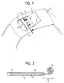
- a vehicle roof 5 can be seen, which with an opening. 7 is provided.
- the opening 7 is a cover 9 of a sliding roof system assigned.
- the lid 9 can between a closed position, in which it closes the opening 7, and an open position shown in Figure 1 be adjusted.
- Below the lid 9 and also below the opening 7 is a roller blind 10 is arranged.
- the blind 10 can, based on the vehicle, after be moved front and back. When the shade 10 is completely back is pushed, the opening 7 is fully released. Fresh air and Sunlight then has free access to the vehicle interior. When the roller blind 10 is pushed completely forward, the opening 7 is covered by the roller blind. Fresh air and sunlight can thus only to a limited extent in the Get inside the vehicle.
- the roller blind 10 is made of a flexible material, such as fabric or a plastic film. At its front edge a bow 12 is provided at a vehicle occupant can attack to the blind to the front or back to move. Laterally along the opening 7, two guides 14 extend, in where the two longitudinal edges of the roller blind, so in the vehicle longitudinal direction considered the right and left edges of the shade 10, are included. in the Area of the rear end of the opening 7 is a winding axis 16, on the blind 10 can be wound up. The winding axis 16 is usually acted upon by a spring, so that the roller blind 10 automatically on the Winding axle 16 is received when the bow 12 to the rear is moved.
- each roller blind is provided with a guide element 18, in the embodiment of Figure 3 as a thin metal strip Spring plate is formed.
- the guide member 18 has in his Initial state, so if there are no external forces acting on it, in Figure 3 visible, curved cross-sectional shape.
- the shade 10 is with the Guide element 18 only on the outer half of the guide element 18 with this connected, so from the outer edge to about the vertex of the guide element 18.
- This area is indicated in FIG. 3 by the reference numeral 20 denotes.
- the roller blind 10 can with the guide member 18 in particular be glued.
- the guide 14 has a generally rectangular cross-section, in section the interior of the guide member 18 together with the at him attached edge portion of the blind 10 is attached.
- the guide On the to the vehicle center directed side, the guide has a leg 22 which is between the roller blind 10 and the vehicle center directed portion of the guide element 18th engages, ie in the area in which the blind 10 is not with the Guide element 18 is glued.
- the guide element 18 can thereby support below the leg to the blind 10 stretched in the transverse direction hold.
- the Guide element 18 In order to wind the blind 10 on the winding axis 16, the Guide element 18 from the first cross-sectional shape shown in Figure 3 in a brought second cross-sectional shape. This is shown in Figure 4 (see the with the Arrow P designated transition region). After leaving the guide 14 and when winding on the winding axis 16, the guide member 18 is flat compressed so that it has a rectangular cross-section whose height the material thickness of the guide element 18 corresponds. In this state can rolled up the shade 10 together with the guide elements 18 to save space become.
- the guide member 18 In addition to the curvature in the transverse direction, the guide member 18 also be curved in the longitudinal direction, so that it rolls up automatically. To this Way can be dispensed with the usual Aufrollfeder on the winding axis 16 become. At the same time you get a constant pulling force. Another effect is an increase in the displacement force, so that it is a self-locking receives. Thus, a manually operated roller blind remains in any intermediate position stand, without an additional roller brake is necessary.
- FIG. 5 shows an alternative embodiment.
- those of the first Embodiment known components will be the same reference numerals used, and it is in this regard referred to the above explanations.
- the guide element shown in Figure 5 18 from a house has flat, rectangular cross-section.
- the blind 10 with only one Half of the guide member 18 connected so that the other half behind the Leg 22 can be added.
Landscapes
- Engineering & Computer Science (AREA)
- Mechanical Engineering (AREA)
- Operating, Guiding And Securing Of Roll- Type Closing Members (AREA)
- Curtains And Furnishings For Windows Or Doors (AREA)
Abstract
Description
- Figur 1 eine perspektivische Ansicht eines Fahrzeugdaches mit einem erfindungsgemäßen Rollo;
- Figur 2 eine schematische Seitenansicht eines erfindungsgemäßen Rollos;
- Figur 3 schematisch einen Schnitt entlang der Ebene III-III von Figur 1;
- Figur 4 in vergrößertem Maßstab den Ausschnitt IV von Figur 2; und
- Figur 5 in einer Ansicht entsprechend derjenigen von Figur 3 eine alternative Ausführungsform der Erfindung.
- 5
- Fahrzeugdach
- 7
- Öffnung
- 9
- Deckel
- 10
- Rollo
- 12
- Spriegel
- 14
- Führung
- 16
- Wickelachse
- 18
- Führungselement
- 20
- Verbindungsbereich
- 22
- Schenkel
Claims (11)
- Rollo (10) für ein Schiebedachsystem, das aus einem flexiblen Material besteht und zwei Führungselemente (18) aufweist, die sich entlang den Längsrändern des Rollos (10) erstrecken und dafür vorgesehen sind, in eine Führung (14) für den entsprechenden Längsrand einzugreifen, dadurch gekennzeichnet, daß das Führungselement (18) ein flacher Streifen ist, der an dem entsprechenden Längsrand befestigt ist, so daß er zusammen mit dem Rollo (10) aufgewickelt werden kann.
- Rollo nach Anspruch 1, dadurch gekennzeichnet, daß das Führungselement (18) im Ausgangszustand eine erste Querschnittsform aufweist, die zur Aufnahme des Führungselementes (18) in der Führung (14) dient, und es in eine zweite Querschnittsform gebracht werden kann, die es ermöglicht, das Rollo (10) platzsparend aufzuwickeln.
- Rollo nach Anspruch 2, dadurch gekennzeichnet, daß das Führungselement (18), wenn es die erste Querschnittsform hat, im Schnitt betrachtet gekrümmt verläuft.
- Rollo nach Anspruch 3, dadurch gekennzeichnet, daß das Rollo (10) auf der vom Krümmungsmittelpunkt abgewandten Seite des Führungselementes (18) befestigt ist.
- Rollo nach Anspruch 1, dadurch gekennzeichnet, daß das Führungselement (18) einen rechteckigen Querschnitt hat.
- Rollo nach einem der vorhergehenden Ansprüche, dadurch gekennzeichnet, daß das Rollo (10), in Längsrichtung betrachtet, nur auf der außenliegenden Seite (20) des Führungselementes (18) befestigt ist.
- Rollo nach einem der vorhergehenden Ansprüche, dadurch gekennzeichnet, daß das Führungselement (18) ein Metallstreifen ist.
- Rollo nach Anspruch 7, dadurch gekennzeichnet, daß das Führungselement (18) aus Federstahl besteht.
- Rollo nach einem der Ansprüche 1 bis 6, dadurch gekennzeichnet, daß das Führungselement (18) ein Kunststoffstreifen ist.
- Rollo nach einem der vorhergehenden Ansprüche, dadurch gekennzeichnet, daß zwei Führungsschienen (14) vorgesehen sind, in denen jeweils ein Längsrand mit dem zugehörigen Führungselement (18) verschiebbar aufgenommen ist.
- Rollo nach Anspruch 10, dadurch gekennzeichnet, daß die Führungsschiene (14) im Schnitt betrachtet einen Schenkel (22) aufweist, der zwischen das Rollo (10) und das Führungselement (18) greift.
Applications Claiming Priority (2)
| Application Number | Priority Date | Filing Date | Title |
|---|---|---|---|
| DE102004017459A DE102004017459A1 (de) | 2004-04-08 | 2004-04-08 | Rollo für ein Schiebedachsystem |
| DE102004017459 | 2004-04-08 |
Publications (4)
| Publication Number | Publication Date |
|---|---|
| EP1588880A2 true EP1588880A2 (de) | 2005-10-26 |
| EP1588880A3 EP1588880A3 (de) | 2007-10-17 |
| EP1588880B1 EP1588880B1 (de) | 2013-03-20 |
| EP1588880B2 EP1588880B2 (de) | 2018-09-19 |
Family
ID=34895536
Family Applications (2)
| Application Number | Title | Priority Date | Filing Date |
|---|---|---|---|
| EP04025215A Revoked EP1584509B1 (de) | 2004-04-08 | 2004-10-22 | Rollo für ein Schiebedachsystem |
| EP04025214.0A Expired - Lifetime EP1588880B2 (de) | 2004-04-08 | 2004-10-22 | Rollo für ein Schiebedachsystem |
Family Applications Before (1)
| Application Number | Title | Priority Date | Filing Date |
|---|---|---|---|
| EP04025215A Revoked EP1584509B1 (de) | 2004-04-08 | 2004-10-22 | Rollo für ein Schiebedachsystem |
Country Status (5)
| Country | Link |
|---|---|
| US (2) | US7114767B2 (de) |
| EP (2) | EP1584509B1 (de) |
| KR (1) | KR20060045572A (de) |
| CN (2) | CN1680127B (de) |
| DE (1) | DE102004017459A1 (de) |
Cited By (11)
| Publication number | Priority date | Publication date | Assignee | Title |
|---|---|---|---|---|
| WO2010022769A1 (en) * | 2008-08-27 | 2010-03-04 | Inalfa Roof Systems Group B.V. | Sunshade assembly and open roof construction provided therewith |
| US8474510B2 (en) | 2009-12-23 | 2013-07-02 | Inalfa Roof Systems Group B.V. | Sunshade assembly and open roof construction provided therewith |
| DE102011010568B4 (de) * | 2011-02-07 | 2013-07-18 | Michael Heidan | Dachsystem für ein Fahrzeug mit einem Heizelement |
| US9090147B2 (en) | 2008-12-02 | 2015-07-28 | Inalfa Roof Systems Group B.V. | Sunshade assembly and open roof construction provided therewith |
| US9840134B2 (en) | 2015-03-04 | 2017-12-12 | Inalfa Roof Systems Group B.V. | Sunshade assembly and open roof construction provided therewith |
| US9969245B2 (en) | 2016-03-21 | 2018-05-15 | Inalfa Roof Systems Group B.V. | Sliding support arrangement and roof assembly for a vehicle |
| EP3003753B1 (de) | 2013-05-31 | 2020-11-04 | Webasto SE | Rolloanordnung |
| US10960740B2 (en) | 2016-05-31 | 2021-03-30 | Inalfa Roof Systems Group B. V. | Open roof construction for a vehicle and rollo assembly for use therein |
| US11414925B2 (en) | 2014-11-06 | 2022-08-16 | Inalfa Roof Systems Group B.V. | Flexible sunscreen and sunshade assembly provided therewith |
| US11752845B2 (en) | 2019-03-20 | 2023-09-12 | Inalfa Roof Systems Group B.V. | Sunshade system and method of manufacturing |
| US12024001B2 (en) | 2019-08-27 | 2024-07-02 | Inalfa Roof Systems Group B.V. | Sunshade system and method of manufacturing parts thereof |
Families Citing this family (40)
| Publication number | Priority date | Publication date | Assignee | Title |
|---|---|---|---|---|
| DE102005024657C5 (de) | 2004-11-19 | 2016-04-21 | Webasto Ag | Rolloanordnung für ein Fahrzeug |
| DE102005048207B3 (de) * | 2005-10-07 | 2006-11-23 | Webasto Ag | Rolloanordnung für ein Kraftfahrzeug |
| DE102006017538B4 (de) | 2006-04-13 | 2010-08-12 | Webasto Ag | Rolloanordnung für ein Fahrzeug |
| DE102006023370A1 (de) * | 2006-05-16 | 2007-11-22 | Brose Fahrzeugteile Gmbh & Co. Kommanditgesellschaft, Coburg | Rollo für Fensterscheiben von Kraftfahrzeugen |
| EP1900560B1 (de) * | 2006-09-13 | 2010-02-24 | ArvinMeritor GmbH | Rollosystem für ein Schiebedach |
| EP1908616B1 (de) * | 2006-10-06 | 2013-04-17 | Inalfa Roof Systems Group B.V. | Sonnenblende und Schiebedachkonstruktion mit solch einer Sonnenblende |
| DE102006057273A1 (de) * | 2006-11-23 | 2008-05-29 | Bos Gmbh & Co. Kg | Schutzvorrichtung für einen Laderaum eines Kraftfahrzeugs |
| DE102006062542A1 (de) | 2006-12-29 | 2008-07-03 | Webasto Ag | Abschattungsvorrichtung eines Fahrzeuges mit einem flexiblen Abdeckelement |
| EP1953018B1 (de) * | 2007-01-31 | 2010-03-17 | ArvinMeritor GmbH | Führungssystem für ein Rollo eines Schiebedachsystems |
| DE102007021049B4 (de) * | 2007-05-04 | 2009-12-03 | Webasto Ag | Rollovorrichtung, insbesondere für ein Schiebedachsystem |
| EP1992511B1 (de) * | 2007-05-04 | 2009-08-19 | Webasto AG | Rollovorrichtung, insbesondere für ein Schiebedachsystem |
| DE102007041298B4 (de) * | 2007-08-31 | 2010-06-10 | Webasto Ag | Rolloanordnung für ein Kraftfahrzeug |
| DE102007047758B4 (de) * | 2007-09-28 | 2009-07-23 | Bos Gmbh & Co. Kg | Schutzvorrichtung für einen Fahrzeuginnenraum |
| DE102008008941B4 (de) | 2008-02-13 | 2023-10-12 | PS : DESIGN+PRODUCTS GmbH | Sonnenschutzanlage mit einem wickelbaren Behang |
| US8316736B2 (en) * | 2008-10-06 | 2012-11-27 | Honda Motor Co., Ltd. | Steering column cover |
| JP5458695B2 (ja) * | 2009-06-29 | 2014-04-02 | アイシン精機株式会社 | ロールシェード装置 |
| DE102010008766C5 (de) * | 2010-02-22 | 2014-04-17 | Webasto SE | Rolloanordnung für ein Kraftfahrzeug |
| JP2011230705A (ja) † | 2010-04-28 | 2011-11-17 | Toyota Motor Corp | 車両用シェード装置 |
| CN102180121A (zh) * | 2011-04-18 | 2011-09-14 | 南车眉山车辆有限公司 | 一种车厢顶盖密封系统 |
| JP2012240500A (ja) * | 2011-05-17 | 2012-12-10 | Aisin Seiki Co Ltd | 車両用ロールシェード装置 |
| EP2529965B1 (de) | 2011-06-01 | 2014-03-12 | Roof Systems Germany GmbH | Rollo für ein Schiebedachsystem |
| DE102011113207B4 (de) * | 2011-09-08 | 2014-07-03 | Webasto Ag | Fahrzeugrolloanordnung und Fahrzeugdach |
| TW201331062A (zh) * | 2012-01-19 | 2013-08-01 | Macauto Ind Co Ltd | 捲簧式天窗遮陽簾 |
| JP5993593B2 (ja) * | 2012-03-21 | 2016-09-14 | 八千代工業株式会社 | サンシェード装置 |
| JP5989378B2 (ja) * | 2012-04-04 | 2016-09-07 | ベバスト ジャパン株式会社 | ロールシェード装置 |
| JP6250917B2 (ja) * | 2012-04-04 | 2017-12-20 | ベバスト ジャパン株式会社 | ロールシェード装置 |
| JP2014189064A (ja) | 2013-03-26 | 2014-10-06 | Aisin Seiki Co Ltd | 車両用ロールシェード装置 |
| JP5713077B2 (ja) * | 2013-10-04 | 2015-05-07 | アイシン精機株式会社 | ロールシェード装置 |
| US10216066B2 (en) | 2013-10-24 | 2019-02-26 | Stephen Pilby | Flexible light control grid with collapsible frame |
| DE102014002961A1 (de) * | 2014-03-06 | 2015-09-24 | Roof Systems Germany Gmbh | Rollosystem für ein Schiebedach |
| EP3109080B1 (de) * | 2015-06-22 | 2018-09-19 | Inalfa Roof Systems Group B.V. | Sonnenschutzanordnung und damit ausgestattete offene dachkonstruktion |
| WO2017123992A1 (en) * | 2016-01-13 | 2017-07-20 | Ciw Enterprises, Inc. | Roll-up doors and method for securing same |
| CN105818655B (zh) * | 2016-04-26 | 2019-12-31 | 昆山隆泰汽车配件有限公司 | 自动翻边防脱式汽车天窗遮阳帘 |
| DE102017129328B4 (de) * | 2017-12-08 | 2023-02-02 | Roof Systems Germany Gmbh | Sonnenschutzrollosystem für ein Kraftfahrzeug |
| DE102019103081A1 (de) * | 2019-02-07 | 2020-08-13 | Webasto SE | Verfahren zur Herstellung eines Textilmoduls für eine Rollobahn |
| WO2020252253A1 (en) | 2019-06-12 | 2020-12-17 | Shanghai Yanfeng Jinqiao Automotive Trim Systems Co. Ltd. | Vehicle component |
| WO2021199862A1 (ja) * | 2020-04-02 | 2021-10-07 | 八千代工業株式会社 | シェードガイド構造 |
| CN112193033A (zh) * | 2020-10-16 | 2021-01-08 | 北京汽车集团越野车有限公司 | 防水帘总成及车辆 |
| SMT202400505T1 (it) | 2021-11-26 | 2025-01-14 | Gluetex Gmbh | Insieme di articoli piatti |
| CN115027229A (zh) * | 2022-05-17 | 2022-09-09 | 杭州福笙家居有限公司 | 一种新能源汽车双曲面不平行天窗遮阳帘 |
Citations (4)
| Publication number | Priority date | Publication date | Assignee | Title |
|---|---|---|---|---|
| DE1269782B (de) | 1965-12-16 | 1968-06-06 | Griesser & Cie | Vorrichtung zur Fuehrung seitlicher Raender eines Vorhanges im Innern von Gleitschienen mit schmalem Schlitz |
| GB1416431A (en) | 1972-02-08 | 1975-12-03 | Hawker Siddeley Aviation Ltd | Window blinds especially for aircraft passenger cabins |
| US4825921A (en) | 1986-05-07 | 1989-05-02 | Rigter Steven M | Blinds, screens, partitions and doors |
| EP1010559A1 (de) | 1997-09-11 | 2000-06-21 | Meritor Automotive GmbH | Sonnenrollo für ein Kraftfahrzeugdach |
Family Cites Families (18)
| Publication number | Priority date | Publication date | Assignee | Title |
|---|---|---|---|---|
| US1882982A (en) † | 1930-11-25 | 1932-10-18 | August J Schmiedeskamp | Rolling screen retaining means |
| US2874770A (en) † | 1955-07-15 | 1959-02-24 | Gen Motors Corp | Self-supporting blind |
| DE1401266A1 (de) † | 1958-11-21 | 1968-10-24 | Tigrett John B | Zu einer Spirale gewickeltes Federband |
| GB1304727A (de) † | 1970-09-15 | 1973-01-31 | ||
| US4707018A (en) * | 1986-02-07 | 1987-11-17 | Irvin Industries, Inc. | Free standing sunshade assembly |
| DE4202342C1 (en) † | 1992-01-29 | 1993-03-18 | Mercedes-Benz Aktiengesellschaft, 7000 Stuttgart, De | Roller blind for motor car windows - has strip of material wound on rod with cross-strip attached to end of material and can be force down against spiral springs |
| US6309076B1 (en) † | 1994-12-29 | 2001-10-30 | Mcvicker Richard E. | Light barrier, screen or reflector |
| CN2251504Y (zh) * | 1995-10-13 | 1997-04-09 | 周小祥 | 车用遮阳通风窗帘 |
| FR2741658B1 (fr) * | 1995-11-29 | 1999-02-26 | Farnier Et Penin Snc | Store de garniture et d'isolation pour toit ouvrant de vehicule automobile |
| US6047762A (en) † | 1998-03-20 | 2000-04-11 | Prince Corporation | Shade control for a vehicle window |
| CN2409077Y (zh) * | 1999-12-21 | 2000-12-06 | 萧世理 | 改良的汽车窗帘轨道 |
| DE10019644B4 (de) * | 2000-04-19 | 2004-09-09 | Webasto Vehicle Systems International Gmbh | Sonnenschutzvorrichtung für ein Fahrzeug |
| DE10140412C1 (de) † | 2001-08-23 | 2002-11-14 | Daimler Chrysler Ag | Rollo zum Abschirmen eines Fahrzeugfensters |
| DE10216186A1 (de) † | 2002-04-04 | 2003-10-16 | Brose Fahrzeugteile | Sonnenschutzrollo für ein Fahrzeugfenster |
| DE10225360C1 (de) * | 2002-06-06 | 2003-10-23 | Webasto Vehicle Sys Int Gmbh | Rollo mit seitlicher Führung |
| FR2841204B1 (fr) * | 2002-06-21 | 2005-01-14 | Webasto Systemes Carrosserie | Module de pavillon pour vehicule automobile |
| DE10253816B3 (de) † | 2002-11-18 | 2004-02-05 | Webasto Vehicle Systems International Gmbh | Rollovorrichtung für ein Fahrzeug |
| DE20309690U1 (de) † | 2003-06-24 | 2003-09-11 | Kuhlemann, Horst, 32825 Blomberg | Sonnenschutzrollo, insbesondere für Kraftfahrzeugfenster |
-
2004
- 2004-04-08 DE DE102004017459A patent/DE102004017459A1/de not_active Ceased
- 2004-10-22 EP EP04025215A patent/EP1584509B1/de not_active Revoked
- 2004-10-22 EP EP04025214.0A patent/EP1588880B2/de not_active Expired - Lifetime
- 2004-10-25 CN CN2004100877132A patent/CN1680127B/zh not_active Expired - Lifetime
- 2004-10-25 US US10/973,081 patent/US7114767B2/en not_active Expired - Lifetime
- 2004-10-25 US US10/973,080 patent/US7114766B2/en not_active Expired - Lifetime
- 2004-10-25 CN CN2004100877170A patent/CN1680128B/zh not_active Ceased
-
2005
- 2005-04-07 KR KR1020050029021A patent/KR20060045572A/ko not_active Withdrawn
Patent Citations (4)
| Publication number | Priority date | Publication date | Assignee | Title |
|---|---|---|---|---|
| DE1269782B (de) | 1965-12-16 | 1968-06-06 | Griesser & Cie | Vorrichtung zur Fuehrung seitlicher Raender eines Vorhanges im Innern von Gleitschienen mit schmalem Schlitz |
| GB1416431A (en) | 1972-02-08 | 1975-12-03 | Hawker Siddeley Aviation Ltd | Window blinds especially for aircraft passenger cabins |
| US4825921A (en) | 1986-05-07 | 1989-05-02 | Rigter Steven M | Blinds, screens, partitions and doors |
| EP1010559A1 (de) | 1997-09-11 | 2000-06-21 | Meritor Automotive GmbH | Sonnenrollo für ein Kraftfahrzeugdach |
Cited By (12)
| Publication number | Priority date | Publication date | Assignee | Title |
|---|---|---|---|---|
| WO2010022769A1 (en) * | 2008-08-27 | 2010-03-04 | Inalfa Roof Systems Group B.V. | Sunshade assembly and open roof construction provided therewith |
| DE212008000124U1 (de) | 2008-08-27 | 2011-05-26 | Inalfa Roof Systems Group B.V. | Sonnenblendenanordnung und damit versehene Offendachkonstruktion |
| US9090147B2 (en) | 2008-12-02 | 2015-07-28 | Inalfa Roof Systems Group B.V. | Sunshade assembly and open roof construction provided therewith |
| US8474510B2 (en) | 2009-12-23 | 2013-07-02 | Inalfa Roof Systems Group B.V. | Sunshade assembly and open roof construction provided therewith |
| DE102011010568B4 (de) * | 2011-02-07 | 2013-07-18 | Michael Heidan | Dachsystem für ein Fahrzeug mit einem Heizelement |
| EP3003753B1 (de) | 2013-05-31 | 2020-11-04 | Webasto SE | Rolloanordnung |
| US11414925B2 (en) | 2014-11-06 | 2022-08-16 | Inalfa Roof Systems Group B.V. | Flexible sunscreen and sunshade assembly provided therewith |
| US9840134B2 (en) | 2015-03-04 | 2017-12-12 | Inalfa Roof Systems Group B.V. | Sunshade assembly and open roof construction provided therewith |
| US9969245B2 (en) | 2016-03-21 | 2018-05-15 | Inalfa Roof Systems Group B.V. | Sliding support arrangement and roof assembly for a vehicle |
| US10960740B2 (en) | 2016-05-31 | 2021-03-30 | Inalfa Roof Systems Group B. V. | Open roof construction for a vehicle and rollo assembly for use therein |
| US11752845B2 (en) | 2019-03-20 | 2023-09-12 | Inalfa Roof Systems Group B.V. | Sunshade system and method of manufacturing |
| US12024001B2 (en) | 2019-08-27 | 2024-07-02 | Inalfa Roof Systems Group B.V. | Sunshade system and method of manufacturing parts thereof |
Also Published As
| Publication number | Publication date |
|---|---|
| US20050225123A1 (en) | 2005-10-13 |
| US7114767B2 (en) | 2006-10-03 |
| EP1584509A2 (de) | 2005-10-12 |
| EP1588880A3 (de) | 2007-10-17 |
| US20050225122A1 (en) | 2005-10-13 |
| CN1680128B (zh) | 2010-09-15 |
| EP1588880B1 (de) | 2013-03-20 |
| EP1584509A3 (de) | 2007-10-17 |
| EP1588880B2 (de) | 2018-09-19 |
| DE102004017459A1 (de) | 2005-10-27 |
| CN1680128A (zh) | 2005-10-12 |
| US7114766B2 (en) | 2006-10-03 |
| EP1584509B1 (de) | 2013-04-03 |
| CN1680127B (zh) | 2010-04-28 |
| CN1680127A (zh) | 2005-10-12 |
| KR20060045572A (ko) | 2006-05-17 |
Similar Documents
| Publication | Publication Date | Title |
|---|---|---|
| EP1588880B2 (de) | Rollo für ein Schiebedachsystem | |
| EP1953018B1 (de) | Führungssystem für ein Rollo eines Schiebedachsystems | |
| DE69202677T2 (de) | Motorisiertes Fensterrolle für gebogenes Fenster. | |
| EP1393939A2 (de) | Rollobahn als Sonnenschutz | |
| DE102011113207B4 (de) | Fahrzeugrolloanordnung und Fahrzeugdach | |
| DE10064513B4 (de) | Rollo | |
| EP2036771A1 (de) | Schutzvorrichtung für einen Innenraum eines Kraftfahrzeugs und Führungsanordnung hierfür | |
| DE2815821C2 (de) | Blendschutz für Fahrzeuge | |
| EP1900560B1 (de) | Rollosystem für ein Schiebedach | |
| DE10225360C1 (de) | Rollo mit seitlicher Führung | |
| DE19856868C2 (de) | Dachanordnung | |
| DE102007021049B4 (de) | Rollovorrichtung, insbesondere für ein Schiebedachsystem | |
| EP2098676A2 (de) | Sonnenschutzanlage mit einem wickelbaren Behang | |
| EP0897821B1 (de) | Rolldach eines Kraftfahrzeugs, insbesondere Personenkraftwagens | |
| DE19738283B4 (de) | Rolldach eines Fahrzeugs | |
| DE202005006415U1 (de) | Baugruppe mit einem Rollo | |
| DE102007002857B4 (de) | Rolloanordnung mit Führungselement | |
| EP1885571B1 (de) | Verdunkelungsvorrichtung mit aufrollbarer rollobahn für eine lichtdurchlässige scheibe | |
| DE202006003831U1 (de) | Rollo für ein Schiebedachsystem | |
| DE10316785A1 (de) | Rollovorrichtung | |
| DE69509010T2 (de) | Sperreinrichtung für Rolladen | |
| DE60222372T2 (de) | Fensterrollo für Kraftfahrzeug mit Zugstange mit mobiler Abdeckung | |
| DE102020108874A1 (de) | Verdunkelungsvorrichtung für ein Kraftfahrzeug, Fahrzeugdach und Kraftfahrzeug | |
| DE3429687C2 (de) | ||
| DE3107001A1 (de) | Tragvorrichtung zur anbringung auf dem dach eines fahrzeuges, insbesondere eines personenkraftwagens |
Legal Events
| Date | Code | Title | Description |
|---|---|---|---|
| PUAI | Public reference made under article 153(3) epc to a published international application that has entered the european phase |
Free format text: ORIGINAL CODE: 0009012 |
|
| AK | Designated contracting states |
Kind code of ref document: A2 Designated state(s): AT BE BG CH CY CZ DE DK EE ES FI FR GB GR HU IE IT LI LU MC NL PL PT RO SE SI SK TR |
|
| AX | Request for extension of the european patent |
Extension state: AL HR LT LV MK |
|
| PUAL | Search report despatched |
Free format text: ORIGINAL CODE: 0009013 |
|
| AK | Designated contracting states |
Kind code of ref document: A3 Designated state(s): AT BE BG CH CY CZ DE DK EE ES FI FR GB GR HU IE IT LI LU MC NL PL PT RO SE SI SK TR |
|
| AX | Request for extension of the european patent |
Extension state: AL HR LT LV MK |
|
| 17P | Request for examination filed |
Effective date: 20080318 |
|
| AKX | Designation fees paid |
Designated state(s): DE FR NL |
|
| 17Q | First examination report despatched |
Effective date: 20100920 |
|
| RAP1 | Party data changed (applicant data changed or rights of an application transferred) |
Owner name: ROOF SYSTEMS GERMANY GMBH |
|
| GRAP | Despatch of communication of intention to grant a patent |
Free format text: ORIGINAL CODE: EPIDOSNIGR1 |
|
| GRAS | Grant fee paid |
Free format text: ORIGINAL CODE: EPIDOSNIGR3 |
|
| GRAA | (expected) grant |
Free format text: ORIGINAL CODE: 0009210 |
|
| AK | Designated contracting states |
Kind code of ref document: B1 Designated state(s): DE FR NL |
|
| REG | Reference to a national code |
Ref country code: DE Ref legal event code: R096 Ref document number: 502004014069 Country of ref document: DE Effective date: 20130516 |
|
| REG | Reference to a national code |
Ref country code: NL Ref legal event code: T3 |
|
| PLBI | Opposition filed |
Free format text: ORIGINAL CODE: 0009260 |
|
| PLBI | Opposition filed |
Free format text: ORIGINAL CODE: 0009260 |
|
| 26 | Opposition filed |
Opponent name: BOS GMBH & CO. KG Effective date: 20131218 |
|
| PLAX | Notice of opposition and request to file observation + time limit sent |
Free format text: ORIGINAL CODE: EPIDOSNOBS2 |
|
| 26 | Opposition filed |
Opponent name: ADVANCED COMFORT SYSTEMS FRANCE SAS-ACS FRANCE Effective date: 20131220 Opponent name: WEBASTO SE Effective date: 20131220 |
|
| REG | Reference to a national code |
Ref country code: DE Ref legal event code: R026 Ref document number: 502004014069 Country of ref document: DE Effective date: 20131218 |
|
| PLAF | Information modified related to communication of a notice of opposition and request to file observations + time limit |
Free format text: ORIGINAL CODE: EPIDOSCOBS2 |
|
| PLBB | Reply of patent proprietor to notice(s) of opposition received |
Free format text: ORIGINAL CODE: EPIDOSNOBS3 |
|
| PLAB | Opposition data, opponent's data or that of the opponent's representative modified |
Free format text: ORIGINAL CODE: 0009299OPPO |
|
| R26 | Opposition filed (corrected) |
Opponent name: ADVANCED COMFORT SYSTEMS FRANCE SAS-ACS FRANCE Effective date: 20131220 |
|
| PLCK | Communication despatched that opposition was rejected |
Free format text: ORIGINAL CODE: EPIDOSNREJ1 |
|
| APBM | Appeal reference recorded |
Free format text: ORIGINAL CODE: EPIDOSNREFNO |
|
| APBP | Date of receipt of notice of appeal recorded |
Free format text: ORIGINAL CODE: EPIDOSNNOA2O |
|
| APAH | Appeal reference modified |
Free format text: ORIGINAL CODE: EPIDOSCREFNO |
|
| REG | Reference to a national code |
Ref country code: FR Ref legal event code: PLFP Year of fee payment: 12 |
|
| APBM | Appeal reference recorded |
Free format text: ORIGINAL CODE: EPIDOSNREFNO |
|
| APBP | Date of receipt of notice of appeal recorded |
Free format text: ORIGINAL CODE: EPIDOSNNOA2O |
|
| APBQ | Date of receipt of statement of grounds of appeal recorded |
Free format text: ORIGINAL CODE: EPIDOSNNOA3O |
|
| APBQ | Date of receipt of statement of grounds of appeal recorded |
Free format text: ORIGINAL CODE: EPIDOSNNOA3O |
|
| REG | Reference to a national code |
Ref country code: FR Ref legal event code: PLFP Year of fee payment: 13 |
|
| REG | Reference to a national code |
Ref country code: FR Ref legal event code: PLFP Year of fee payment: 14 |
|
| APBU | Appeal procedure closed |
Free format text: ORIGINAL CODE: EPIDOSNNOA9O |
|
| PUAH | Patent maintained in amended form |
Free format text: ORIGINAL CODE: 0009272 |
|
| STAA | Information on the status of an ep patent application or granted ep patent |
Free format text: STATUS: PATENT MAINTAINED AS AMENDED |
|
| 27A | Patent maintained in amended form |
Effective date: 20180919 |
|
| AK | Designated contracting states |
Kind code of ref document: B2 Designated state(s): DE FR NL |
|
| REG | Reference to a national code |
Ref country code: DE Ref legal event code: R102 Ref document number: 502004014069 Country of ref document: DE |
|
| REG | Reference to a national code |
Ref country code: FR Ref legal event code: PLFP Year of fee payment: 15 |
|
| REG | Reference to a national code |
Ref country code: NL Ref legal event code: FP |
|
| PGFP | Annual fee paid to national office [announced via postgrant information from national office to epo] |
Ref country code: NL Payment date: 20231019 Year of fee payment: 20 |
|
| PGFP | Annual fee paid to national office [announced via postgrant information from national office to epo] |
Ref country code: FR Payment date: 20231023 Year of fee payment: 20 Ref country code: DE Payment date: 20231026 Year of fee payment: 20 |
|
| P01 | Opt-out of the competence of the unified patent court (upc) registered |
Effective date: 20240117 |
|
| REG | Reference to a national code |
Ref country code: DE Ref legal event code: R071 Ref document number: 502004014069 Country of ref document: DE |
|
| REG | Reference to a national code |
Ref country code: NL Ref legal event code: MK Effective date: 20241021 |