EP1588078B1 - Hydrostatisches getriebe - Google Patents
Hydrostatisches getriebe Download PDFInfo
- Publication number
- EP1588078B1 EP1588078B1 EP04704185A EP04704185A EP1588078B1 EP 1588078 B1 EP1588078 B1 EP 1588078B1 EP 04704185 A EP04704185 A EP 04704185A EP 04704185 A EP04704185 A EP 04704185A EP 1588078 B1 EP1588078 B1 EP 1588078B1
- Authority
- EP
- European Patent Office
- Prior art keywords
- hydraulic motor
- speed
- hydrostatic transmission
- hydraulic
- vehicle
- Prior art date
- Legal status (The legal status is an assumption and is not a legal conclusion. Google has not performed a legal analysis and makes no representation as to the accuracy of the status listed.)
- Expired - Lifetime
Links
- 230000002706 hydrostatic effect Effects 0.000 title claims abstract description 20
- 230000005540 biological transmission Effects 0.000 title claims description 23
- 239000012530 fluid Substances 0.000 claims description 13
- 230000009467 reduction Effects 0.000 claims description 11
- 230000003044 adaptive effect Effects 0.000 claims description 4
- 238000013459 approach Methods 0.000 claims description 2
- 230000001105 regulatory effect Effects 0.000 claims 1
- 238000006073 displacement reaction Methods 0.000 description 25
- 230000001133 acceleration Effects 0.000 description 10
- 230000006870 function Effects 0.000 description 4
- 241000219098 Parthenocissus Species 0.000 description 3
- 230000008859 change Effects 0.000 description 3
- 230000001419 dependent effect Effects 0.000 description 3
- 238000010586 diagram Methods 0.000 description 3
- 238000010521 absorption reaction Methods 0.000 description 2
- 238000002485 combustion reaction Methods 0.000 description 1
- 238000004891 communication Methods 0.000 description 1
- 238000010276 construction Methods 0.000 description 1
- 230000000694 effects Effects 0.000 description 1
- 238000000034 method Methods 0.000 description 1
- 230000008569 process Effects 0.000 description 1
- 230000004044 response Effects 0.000 description 1
- 230000002441 reversible effect Effects 0.000 description 1
- 210000002023 somite Anatomy 0.000 description 1
- 230000007704 transition Effects 0.000 description 1
Images

Classifications
-
- B—PERFORMING OPERATIONS; TRANSPORTING
- B60—VEHICLES IN GENERAL
- B60W—CONJOINT CONTROL OF VEHICLE SUB-UNITS OF DIFFERENT TYPE OR DIFFERENT FUNCTION; CONTROL SYSTEMS SPECIALLY ADAPTED FOR HYBRID VEHICLES; ROAD VEHICLE DRIVE CONTROL SYSTEMS FOR PURPOSES NOT RELATED TO THE CONTROL OF A PARTICULAR SUB-UNIT
- B60W10/00—Conjoint control of vehicle sub-units of different type or different function
- B60W10/10—Conjoint control of vehicle sub-units of different type or different function including control of change-speed gearings
- B60W10/101—Infinitely variable gearings
- B60W10/103—Infinitely variable gearings of fluid type
-
- F—MECHANICAL ENGINEERING; LIGHTING; HEATING; WEAPONS; BLASTING
- F16—ENGINEERING ELEMENTS AND UNITS; GENERAL MEASURES FOR PRODUCING AND MAINTAINING EFFECTIVE FUNCTIONING OF MACHINES OR INSTALLATIONS; THERMAL INSULATION IN GENERAL
- F16H—GEARING
- F16H61/00—Control functions within control units of change-speed- or reversing-gearings for conveying rotary motion ; Control of exclusively fluid gearing, friction gearing, gearings with endless flexible members or other particular types of gearing
- F16H61/38—Control of exclusively fluid gearing
- F16H61/40—Control of exclusively fluid gearing hydrostatic
- F16H61/46—Automatic regulation in accordance with output requirements
-
- B—PERFORMING OPERATIONS; TRANSPORTING
- B60—VEHICLES IN GENERAL
- B60K—ARRANGEMENT OR MOUNTING OF PROPULSION UNITS OR OF TRANSMISSIONS IN VEHICLES; ARRANGEMENT OR MOUNTING OF PLURAL DIVERSE PRIME-MOVERS IN VEHICLES; AUXILIARY DRIVES FOR VEHICLES; INSTRUMENTATION OR DASHBOARDS FOR VEHICLES; ARRANGEMENTS IN CONNECTION WITH COOLING, AIR INTAKE, GAS EXHAUST OR FUEL SUPPLY OF PROPULSION UNITS IN VEHICLES
- B60K31/00—Vehicle fittings, acting on a single sub-unit only, for automatically controlling vehicle speed, i.e. preventing speed from exceeding an arbitrarily established velocity or maintaining speed at a particular velocity, as selected by the vehicle operator
- B60K31/06—Vehicle fittings, acting on a single sub-unit only, for automatically controlling vehicle speed, i.e. preventing speed from exceeding an arbitrarily established velocity or maintaining speed at a particular velocity, as selected by the vehicle operator including fluid pressure actuated servomechanism in which the vehicle velocity affecting element is actuated by fluid pressure
- B60K31/10—Vehicle fittings, acting on a single sub-unit only, for automatically controlling vehicle speed, i.e. preventing speed from exceeding an arbitrarily established velocity or maintaining speed at a particular velocity, as selected by the vehicle operator including fluid pressure actuated servomechanism in which the vehicle velocity affecting element is actuated by fluid pressure and means for comparing one electrical quantity, e.g. voltage, pulse, waveform, flux, or the like, with another quantity of a like kind, which comparison means is involved in the development of a pressure which is fed into the controlling means
-
- B—PERFORMING OPERATIONS; TRANSPORTING
- B60—VEHICLES IN GENERAL
- B60T—VEHICLE BRAKE CONTROL SYSTEMS OR PARTS THEREOF; BRAKE CONTROL SYSTEMS OR PARTS THEREOF, IN GENERAL; ARRANGEMENT OF BRAKING ELEMENTS ON VEHICLES IN GENERAL; PORTABLE DEVICES FOR PREVENTING UNWANTED MOVEMENT OF VEHICLES; VEHICLE MODIFICATIONS TO FACILITATE COOLING OF BRAKES
- B60T13/00—Transmitting braking action from initiating means to ultimate brake actuator with power assistance or drive; Brake systems incorporating such transmitting means, e.g. air-pressure brake systems
- B60T13/10—Transmitting braking action from initiating means to ultimate brake actuator with power assistance or drive; Brake systems incorporating such transmitting means, e.g. air-pressure brake systems with fluid assistance, drive, or release
- B60T13/66—Electrical control in fluid-pressure brake systems
-
- B—PERFORMING OPERATIONS; TRANSPORTING
- B60—VEHICLES IN GENERAL
- B60W—CONJOINT CONTROL OF VEHICLE SUB-UNITS OF DIFFERENT TYPE OR DIFFERENT FUNCTION; CONTROL SYSTEMS SPECIALLY ADAPTED FOR HYBRID VEHICLES; ROAD VEHICLE DRIVE CONTROL SYSTEMS FOR PURPOSES NOT RELATED TO THE CONTROL OF A PARTICULAR SUB-UNIT
- B60W10/00—Conjoint control of vehicle sub-units of different type or different function
- B60W10/04—Conjoint control of vehicle sub-units of different type or different function including control of propulsion units
- B60W10/06—Conjoint control of vehicle sub-units of different type or different function including control of propulsion units including control of combustion engines
-
- B—PERFORMING OPERATIONS; TRANSPORTING
- B60—VEHICLES IN GENERAL
- B60W—CONJOINT CONTROL OF VEHICLE SUB-UNITS OF DIFFERENT TYPE OR DIFFERENT FUNCTION; CONTROL SYSTEMS SPECIALLY ADAPTED FOR HYBRID VEHICLES; ROAD VEHICLE DRIVE CONTROL SYSTEMS FOR PURPOSES NOT RELATED TO THE CONTROL OF A PARTICULAR SUB-UNIT
- B60W10/00—Conjoint control of vehicle sub-units of different type or different function
- B60W10/10—Conjoint control of vehicle sub-units of different type or different function including control of change-speed gearings
-
- B—PERFORMING OPERATIONS; TRANSPORTING
- B60—VEHICLES IN GENERAL
- B60W—CONJOINT CONTROL OF VEHICLE SUB-UNITS OF DIFFERENT TYPE OR DIFFERENT FUNCTION; CONTROL SYSTEMS SPECIALLY ADAPTED FOR HYBRID VEHICLES; ROAD VEHICLE DRIVE CONTROL SYSTEMS FOR PURPOSES NOT RELATED TO THE CONTROL OF A PARTICULAR SUB-UNIT
- B60W10/00—Conjoint control of vehicle sub-units of different type or different function
- B60W10/18—Conjoint control of vehicle sub-units of different type or different function including control of braking systems
-
- B—PERFORMING OPERATIONS; TRANSPORTING
- B60—VEHICLES IN GENERAL
- B60W—CONJOINT CONTROL OF VEHICLE SUB-UNITS OF DIFFERENT TYPE OR DIFFERENT FUNCTION; CONTROL SYSTEMS SPECIALLY ADAPTED FOR HYBRID VEHICLES; ROAD VEHICLE DRIVE CONTROL SYSTEMS FOR PURPOSES NOT RELATED TO THE CONTROL OF A PARTICULAR SUB-UNIT
- B60W30/00—Purposes of road vehicle drive control systems not related to the control of a particular sub-unit, e.g. of systems using conjoint control of vehicle sub-units
- B60W30/18—Propelling the vehicle
- B60W30/1819—Propulsion control with control means using analogue circuits, relays or mechanical links
-
- F—MECHANICAL ENGINEERING; LIGHTING; HEATING; WEAPONS; BLASTING
- F16—ENGINEERING ELEMENTS AND UNITS; GENERAL MEASURES FOR PRODUCING AND MAINTAINING EFFECTIVE FUNCTIONING OF MACHINES OR INSTALLATIONS; THERMAL INSULATION IN GENERAL
- F16H—GEARING
- F16H61/00—Control functions within control units of change-speed- or reversing-gearings for conveying rotary motion ; Control of exclusively fluid gearing, friction gearing, gearings with endless flexible members or other particular types of gearing
- F16H61/38—Control of exclusively fluid gearing
- F16H61/40—Control of exclusively fluid gearing hydrostatic
- F16H61/4157—Control of braking, e.g. preventing pump over-speeding when motor acts as a pump
-
- F—MECHANICAL ENGINEERING; LIGHTING; HEATING; WEAPONS; BLASTING
- F16—ENGINEERING ELEMENTS AND UNITS; GENERAL MEASURES FOR PRODUCING AND MAINTAINING EFFECTIVE FUNCTIONING OF MACHINES OR INSTALLATIONS; THERMAL INSULATION IN GENERAL
- F16H—GEARING
- F16H61/00—Control functions within control units of change-speed- or reversing-gearings for conveying rotary motion ; Control of exclusively fluid gearing, friction gearing, gearings with endless flexible members or other particular types of gearing
- F16H61/38—Control of exclusively fluid gearing
- F16H61/40—Control of exclusively fluid gearing hydrostatic
- F16H61/42—Control of exclusively fluid gearing hydrostatic involving adjustment of a pump or motor with adjustable output or capacity
- F16H61/421—Motor capacity control by electro-hydraulic control means, e.g. using solenoid valves
-
- F—MECHANICAL ENGINEERING; LIGHTING; HEATING; WEAPONS; BLASTING
- F16—ENGINEERING ELEMENTS AND UNITS; GENERAL MEASURES FOR PRODUCING AND MAINTAINING EFFECTIVE FUNCTIONING OF MACHINES OR INSTALLATIONS; THERMAL INSULATION IN GENERAL
- F16H—GEARING
- F16H61/00—Control functions within control units of change-speed- or reversing-gearings for conveying rotary motion ; Control of exclusively fluid gearing, friction gearing, gearings with endless flexible members or other particular types of gearing
- F16H61/38—Control of exclusively fluid gearing
- F16H61/40—Control of exclusively fluid gearing hydrostatic
- F16H61/46—Automatic regulation in accordance with output requirements
- F16H61/47—Automatic regulation in accordance with output requirements for achieving a target output speed
-
- F—MECHANICAL ENGINEERING; LIGHTING; HEATING; WEAPONS; BLASTING
- F16—ENGINEERING ELEMENTS AND UNITS; GENERAL MEASURES FOR PRODUCING AND MAINTAINING EFFECTIVE FUNCTIONING OF MACHINES OR INSTALLATIONS; THERMAL INSULATION IN GENERAL
- F16H—GEARING
- F16H61/00—Control functions within control units of change-speed- or reversing-gearings for conveying rotary motion ; Control of exclusively fluid gearing, friction gearing, gearings with endless flexible members or other particular types of gearing
- F16H61/38—Control of exclusively fluid gearing
- F16H61/40—Control of exclusively fluid gearing hydrostatic
- F16H61/46—Automatic regulation in accordance with output requirements
- F16H61/472—Automatic regulation in accordance with output requirements for achieving a target output torque
-
- B—PERFORMING OPERATIONS; TRANSPORTING
- B60—VEHICLES IN GENERAL
- B60K—ARRANGEMENT OR MOUNTING OF PROPULSION UNITS OR OF TRANSMISSIONS IN VEHICLES; ARRANGEMENT OR MOUNTING OF PLURAL DIVERSE PRIME-MOVERS IN VEHICLES; AUXILIARY DRIVES FOR VEHICLES; INSTRUMENTATION OR DASHBOARDS FOR VEHICLES; ARRANGEMENTS IN CONNECTION WITH COOLING, AIR INTAKE, GAS EXHAUST OR FUEL SUPPLY OF PROPULSION UNITS IN VEHICLES
- B60K17/00—Arrangement or mounting of transmissions in vehicles
- B60K17/04—Arrangement or mounting of transmissions in vehicles characterised by arrangement, location, or kind of gearing
- B60K17/10—Arrangement or mounting of transmissions in vehicles characterised by arrangement, location, or kind of gearing of fluid gearing
-
- B—PERFORMING OPERATIONS; TRANSPORTING
- B60—VEHICLES IN GENERAL
- B60W—CONJOINT CONTROL OF VEHICLE SUB-UNITS OF DIFFERENT TYPE OR DIFFERENT FUNCTION; CONTROL SYSTEMS SPECIALLY ADAPTED FOR HYBRID VEHICLES; ROAD VEHICLE DRIVE CONTROL SYSTEMS FOR PURPOSES NOT RELATED TO THE CONTROL OF A PARTICULAR SUB-UNIT
- B60W2510/00—Input parameters relating to a particular sub-units
- B60W2510/10—Change speed gearings
- B60W2510/107—Temperature
-
- B—PERFORMING OPERATIONS; TRANSPORTING
- B60—VEHICLES IN GENERAL
- B60W—CONJOINT CONTROL OF VEHICLE SUB-UNITS OF DIFFERENT TYPE OR DIFFERENT FUNCTION; CONTROL SYSTEMS SPECIALLY ADAPTED FOR HYBRID VEHICLES; ROAD VEHICLE DRIVE CONTROL SYSTEMS FOR PURPOSES NOT RELATED TO THE CONTROL OF A PARTICULAR SUB-UNIT
- B60W2720/00—Output or target parameters relating to overall vehicle dynamics
- B60W2720/10—Longitudinal speed
- B60W2720/106—Longitudinal acceleration
-
- F—MECHANICAL ENGINEERING; LIGHTING; HEATING; WEAPONS; BLASTING
- F16—ENGINEERING ELEMENTS AND UNITS; GENERAL MEASURES FOR PRODUCING AND MAINTAINING EFFECTIVE FUNCTIONING OF MACHINES OR INSTALLATIONS; THERMAL INSULATION IN GENERAL
- F16H—GEARING
- F16H59/00—Control inputs to control units of change-speed-, or reversing-gearings for conveying rotary motion
- F16H59/36—Inputs being a function of speed
- F16H59/38—Inputs being a function of speed of gearing elements
- F16H59/40—Output shaft speed
-
- F—MECHANICAL ENGINEERING; LIGHTING; HEATING; WEAPONS; BLASTING
- F16—ENGINEERING ELEMENTS AND UNITS; GENERAL MEASURES FOR PRODUCING AND MAINTAINING EFFECTIVE FUNCTIONING OF MACHINES OR INSTALLATIONS; THERMAL INSULATION IN GENERAL
- F16H—GEARING
- F16H59/00—Control inputs to control units of change-speed-, or reversing-gearings for conveying rotary motion
- F16H59/50—Inputs being a function of the status of the machine, e.g. position of doors or safety belts
- F16H59/54—Inputs being a function of the status of the machine, e.g. position of doors or safety belts dependent on signals from the brakes, e.g. parking brakes
-
- F—MECHANICAL ENGINEERING; LIGHTING; HEATING; WEAPONS; BLASTING
- F16—ENGINEERING ELEMENTS AND UNITS; GENERAL MEASURES FOR PRODUCING AND MAINTAINING EFFECTIVE FUNCTIONING OF MACHINES OR INSTALLATIONS; THERMAL INSULATION IN GENERAL
- F16H—GEARING
- F16H59/00—Control inputs to control units of change-speed-, or reversing-gearings for conveying rotary motion
- F16H59/68—Inputs being a function of gearing status
- F16H59/70—Inputs being a function of gearing status dependent on the ratio established
-
- F—MECHANICAL ENGINEERING; LIGHTING; HEATING; WEAPONS; BLASTING
- F16—ENGINEERING ELEMENTS AND UNITS; GENERAL MEASURES FOR PRODUCING AND MAINTAINING EFFECTIVE FUNCTIONING OF MACHINES OR INSTALLATIONS; THERMAL INSULATION IN GENERAL
- F16H—GEARING
- F16H59/00—Control inputs to control units of change-speed-, or reversing-gearings for conveying rotary motion
- F16H59/68—Inputs being a function of gearing status
- F16H59/72—Inputs being a function of gearing status dependent on oil characteristics, e.g. temperature, viscosity
Definitions
- the invention relates to a hydrostatic transmission according to the closer defined in the preamble of claim 1.
- Generic hydrostatic transmission as shown in DE 43 12 716 are known, for example, in construction machines, such as wheeled excavators, used to drive the mobile vehicle.
- a hydraulic pump is operated with a hydraulic motor in the open circuit, wherein the hydraulic pump takes pressure fluid from a pressure fluid reservoir and supplies them via a working line to the hydraulic motor.
- the hydraulic motor downstream of a switchable transmission.
- the hydraulic fluid flow leaving the hydraulic motor may be limited by pressure relief valves to prevent improper acceleration of the vehicle when driving downhill.
- the brake valve limits the hydraulic fluid flow of the hydraulic motor so that a hydraulic pressure builds up in the return line, which generates a braking torque together with the set displacement of the hydraulic motor.
- This braking torque is changed by the change in the displacement of the hydraulic motor and acts, depending on the ratio of the downstream transmission and thus the engaged gear on the drive wheels. If the minimum displacement of the hydraulic motor is set and the downward force acting on the vehicle by the gradient of the slope exceeds the possible braking torque which the hydraulic motor generates with the aid of the brake valves, this can lead to dangerous driving situations.
- the EP 0 530 842 B1 discloses a reversible hydrostatic transmission with brake valve in which the displacement of the hydraulic motor is adjusted in response to the hydraulic pressure generated by the brake valve.
- the hydraulic motor is swung when driving on a steep slope to its maximum displacement, creating a maximum to be generated braking torque of the hydraulic motor is generated. Since the adjustment of the hydraulic motor takes place exclusively as a function of the dynamic pressure generated by the brake valve, it is not possible to influence the delay generated by this braking torque. Also, this delay, depending on the set ratio of the downstream reduction gear, has different effects on the vehicle.
- the present invention has for its object to provide a hydrostatic transmission, which brings the vehicle even in overrun operation in no impermissible driving situations.
- the object is achieved with a, including the characterizing features of the main claim having, generic hydrostatic transmission.
- the hydraulic motor is controlled by an electronic control unit so that its absorption volume is adjusted such that a required speed request is achieved with the vehicle.
- the desired speed of the electronic control unit is supplied, which, for example, from the accelerator pedal position or the position of the main control valve or by means of a pressure sensor in the control pressure of the accelerator pedal to Main control valve or a rotary encoder on the accelerator pedal is determined.
- the electronic control receives a signal which corresponds to the vehicle speed, which can be taken, for example, an output speed of the transmission or the hydraulic motor speed in combination with the reduction of the gearbox.
- the minimum intake volume of the engine is not mechanically limited.
- the displacement of the hydraulic motor is adjusted so that the desired vehicle speed corresponds to the actual vehicle speed.
- a control pressure-dependent adjustable or an electrically proportionally adjustable hydraulic motor with superimposed pressure control is used.
- a brake valve is mounted on the engine and there are secondary pressure relief valves between the engine and the brake valve.
- the hydraulic motor adjusts its displacement according to the control pressure, which results from the given pressure fluid quantity and the available driving performance. If the current speed of the setpoint speed approaches, the control signal to the hydraulic motor is adapted accordingly, depending on the current vehicle acceleration and / or the derived difference between the setpoint and actual speed (characteristic field), so that the deviation from the setpoint and actual Speed is as small as possible.
- the same thing Map is also used when the current speed is greater than the target speed.
- the electronic controller controls the hydraulic motor so that it is adjusted to a larger displacement the speed is reduced.
- the inlet pressure to the hydraulic motor drops below a defined value, the brake valve begins to close, whereby a hydraulic pressure is built up on the hydraulic motor, which generates a brake pressure and thus a braking torque in conjunction with the set displacement of the hydraulic motor. Due to the degree of displacement in brake mode, it is possible to influence the degree of deceleration.
- the displacement adjustment is electronically controlled in braking mode as a function of the deviation between the desired value of the delay, which takes the electronic control a stored map, and the deceleration actual value. It is possible to select multiple thresholds, such as "hard”, “medium” and “soft”, for the target value delay.
- the actual deceleration is determined by the electronic control from the change of the output speed. Thus, regardless of the switched ratio of the downstream reduction gear, always the same delay is adjusted. It is possible to perform the electronic control so that the "hard” deceleration is automatically set when the driver simultaneously operates the service brake. As a result, the service brakes are less heavily loaded.
- the transition from the normal driving state to the crawl speed is transferred according to the preselected deceleration.
- the hydrostatic transmission according to the invention thus makes it possible to achieve the predetermined vehicle deceleration or acceleration independently of the pressure fluid temperature, the quantity of hydraulic fluid and downstream reduction stages. It also ensures that no driving critical conditions can occur even when driving downhill.
- the electronic control unit and the hydraulic motor control valve can also be arranged in the undercarriage.
- first gear there is a single map for all vehicle speed classes, for example 20 km / h, 25 km / h, 34 km / h maximum speed, d. h., in first gear the maximum working speed is the same.
- second gear there is a map for each speed class. This map or the function is stored in the electronic control.
Landscapes
- Engineering & Computer Science (AREA)
- Mechanical Engineering (AREA)
- General Engineering & Computer Science (AREA)
- Chemical & Material Sciences (AREA)
- Combustion & Propulsion (AREA)
- Transportation (AREA)
- Fluid Mechanics (AREA)
- Physics & Mathematics (AREA)
- Automation & Control Theory (AREA)
- Control Of Fluid Gearings (AREA)
- Control Of Transmission Device (AREA)
- Crystals, And After-Treatments Of Crystals (AREA)
- Transmission Of Braking Force In Braking Systems (AREA)
Description
- Die Erfindung bezieht sich auf ein hydrostatisches Getriebe nach der im Oberbegriff von Anspruch 1 näher definierten Art.
- Gattungsgemäße hydrostatische Getriebe, wie aus der
DE 43 12 716 bekannt, werden beispielsweise in Baumaschinen, wie Radbagger, zum Antrieb des mobilen Fahrzeugs verwendet. Hierbei wird eine hydraulische Pumpe mit einem hydraulischen Motor im offenen Kreislauf betrieben, wobei die hydraulische Pumpe Druckflüssigkeit aus einem Druckflüssigkeitsreservoir entnimmt und diese über eine Arbeitsleitung dem hydraulischen Motor zuführt. Häufig ist dem hydraulischen Motor ein schaltbares Getriebe nachgeordnet. Der Druckflüssigkeitsstrom, welcher den Hydraulikmotor verläßt, kann über Druckbegrenzungsventile begrenzt werden, um ein unzulässiges Beschleunigen des Fahrzeugs bei einer Fahrt hangabwärts zu verhindern. Hierbei begrenzt das Bremsventil den Druckflüssigkeitsstrom des Hydromotors so, dass sich in der rückfließenden Arbeitsleitung ein hydraulischer Druck aufbaut, welcher zusammen mit dem eingestellten Schluckvolumen des Hydromotors ein Bremsmoment erzeugt. Dieses Bremsmoment verändert sich durch die Veränderung des Schluckvolumens des Hydromotors und wirkt, je nach Untersetzung des nachgeschalteten Getriebes und somit des eingelegten Ganges, auf die Antriebsräder. Ist das minimale Schluckvolumen des Hydromotors eingestellt und die Hangabtriebskraft, welche durch die Steigung des Hangs auf das Fahrzeug wirkt, übersteigt das mögliche Bremsmoment, welches der Hydromotor mit Hilfe der Bremsventile erzeugt, so kann es zu gefährlichen Fahrsituationen kommen. - Die
EP 0 530 842 B1 offenbart ein reversierbares hydrostatisches Getriebes mit Bremsventil, bei welchem das Schluckvolumen des Hydromotors in Abhängigkeit von dem durch das Bremsventil erzeugten hydraulischen Druck verstellt wird. Somit wird der Hydromotor bei Fahrt in starkem Gefälle auf sein maximales Schluckvolumen ausgeschwenkt, wodurch ein maximal zu erzeugendes Bremsmoment-des Hydromotors erzeugt wird. Da die Verstellung des Hydromotors ausschließlich in Abhängigkeit des von dem Bremsventil erzeugten Staudrucks erfolgt, ist es nicht möglich, die durch dieses Bremsmoment erzeugte Verzögerung zu beeinflussen. Auch wirkt sich diese Verzögerung, je nach eingestellter Untersetzung des nachgeschalteten Untersetzungsgetriebes, unterschiedlich auf das Fahrzeug aus. - Vorliegender Erfindung liegt die Aufgabe zugrunde, ein hydrostatisches Getriebe zu schaffen, welches das Fahrzeug auch im Schubbetrieb in keine unzulässigen Fahrsituationen bringt.
- Die Aufgabe wird mit einem, auch die kennzeichnenden Merkmale des Hauptanspruchs aufweisenden, gattungsgemäßen hydrostatischen Getriebe gelöst.
- Erfindungsgemäß wird der Hydromotor von einer elektronischen Steuereinheit so angesteuert, dass sein Schluckvolumen derart verstellt wird, dass ein geforderter Geschwindigkeitswunsch mit dem Fahrzeug erreicht wird. Hierzu wird der Geschwindigkeitswunsch der elektronischen Steuereinheit zugeführt, welcher beispielsweise aus der Fahrpedalstellung oder der Stellung des Hauptsteuerventils oder mit Hilfe eines Drucksensors im Steuerdruck des Fahrpedals zum Hauptsteuerventil oder einem Drehwinkelgeber am Fahrpedal ermittelt wird. Des weiteren erhält die elektronische Steuerung ein Signal, welches der Fahrzeuggeschwindigkeit entspricht, welche beispielsweise einer Abtriebsdrehzahl des Getriebes oder der Hydromotordrehzahl in Kombination mit der Untersetzung des Schaltgetriebes entnommen werden kann. Das minimale Schluckvolumen des Motors wird nicht mechanisch begrenzt. Weicht die gemessene Fahrzeuggeschwindigkeit von der gewünschten Fahrzeuggeschwindigkeit ab, so wird das Schluckvolumen des Hydromotors so verstellt, dass die gewünschte Fahrzeuggeschwindigkeit der tatsächlichen Fahrzeuggeschwindigkeit entspricht. Hierzu wird ein steuerdruckabhängig verstellbarer oder ein elektrisch proportional verstellbarer Hydromotor mit überlagerter Druckregelung verwendet. An dem Motor ist ein Bremsventil angebaut, und es befinden sich zwischen dem Motor und dem Bremsventil sekundär wirkende Druckbegrenzungsventile. Im Beschleunigungsvorgang, dem Zugbetrieb, wird das Steuersignal der elektronischen Steuerung zum Hydromotor entsprechend der aktuellen Dieselmotor-Drehzahl und der Fahrpedalstellung, somit dem Volumenstrom, so eingestellt, dass damit die entsprechend mögliche Geschwindigkeit erreicht werden kann, d. h., das Signal ist voreilend.
- Der Hydromotor verstellt sein Schluckvolumen entsprechend dem Regeldruck, welcher sich aus der gegebenen Druckflüssigkeitsmenge und der verfügbaren Fahrleistung ergibt. Nähert sich die aktuelle Geschwindigkeit der Soll-Geschwindigkeit, wird, abhängig von der aktuellen Fahrzeugbeschleunigung und/oder der abgeleiteten Differenz von Soll- und Ist-Geschwindigkeit (Kennfeld), das Steuersignal zum Hydromotor entsprechend angepaßt, damit die Abweichung von Soll- und Ist-Geschwin-digkeit möglichst klein ist. Dasselbe Kennfeld wird auch dann verwendet, wenn die aktuelle Geschwindigkeit größer als die Soll-Geschwindigkeit ist.
- Weist das Fahrzeug eine höhere Ist-Geschwindigkeit gegenüber der Soll-Geschwindigkeit auf, welche beispielsweise durch eine Hangabwärtsfahrt oder die Veränderung des Fahrpedals auf geringere Geschwindigkeit entsteht, so steuert die elektronische Steuerung den Hydromotor so an, dass dieser auf ein größeres Schluckvolumen verstellt wird, wodurch die Geschwindigkeit verringert wird. Sinkt hierdurch der Zulaufdruck zum Hydromotor unter einen definierten Wert, so beginnt das Bremsventil zu schließen, wodurch am Hydromotor ablaufseitig ein hydraulischer Druck aufgebaut wird, welcher in Verbindung mit dem eingestellten Schluckvolumen des Hydromotors einen Bremsdruck und somit ein Bremsmoment erzeugt. Durch den Grad der Schluckvolumenverstellung im Bremsbetrieb besteht die Möglichkeit, den Grad der Verzögerung zu beeinflussen. Die Schluckvolumenverstellung wird im Bremsbetrieb in Abhängigkeit von der Abweichung zwischen dem Soll-Wert der Verzögerung, welche die elektronische Steuerung einem abgespeicherten Kennfeld entnimmt, und dem Verzögerungs-Ist-Wert elektronisch geregelt. Es besteht die Möglichkeit, mehrere Grenzwerte, beispielsweise "Hart", "Mittel" und "Weich", für die Soll-Wert-Verzögerung zu wählen. Die Ist-Verzögerung ermittelt die elektronische Steuerung aus der Änderung der Abtriebsdrehzahl. Somit wird, unabhängig von der geschalteten Untersetzung des nachgeschalteten Untersetzungsgetriebes, immer die gleiche Verzögerung eingeregelt. Es besteht die Möglichkeit, die elektronische Steuerung so auszuführen, dass automatisch die Verzögerung "Hart" eingestellt wird, wenn gleichzeitig der Fahrer die Betriebsbremse betätigt. Hierdurch werden die Betriebsbremsen weniger stark belastet.
- In einer weiteren Ausgestaltungsform befindet sich ein Temperatursensor im Hydrauliktank, mit dessen Signal bei Übertemperatur die zulässige Fahrgeschwindigkeit reduziert wird. In einer weiteren Ausgestaltungsform besteht die Möglichkeit, bei der Warmlaufphase im Winterbetrieb die maximale Geschwindigkeit zu begrenzen, bis die Betriebstemperatur erreicht ist.
- In einer weiteren Ausgestaltungsform besteht die Möglichkeit, die Geschwindigkeit in Abhängigkeit der Ölqualität zu begrenzen.
- In einer weiteren Ausgestaltungsform besteht die Möglichkeit, das Schluckvolumen des Hydromotors in seinem maximalen Schluckvolumen zu halten, solange sich das Fahrzeug in der Stellung für den Kriechgang befindet.
- Der Übergang vom normalen Fahrzustand in den Kriechgang wird entsprechend der vorgewählten Verzögerung übergeleitet.
- Indem bei dem hydrostatischen Getriebe ein steuerdruckabhängig verstellbarer Hydromotor oder ein elektrisch proportional verstellter Hydromotor mit überlagerter Druckregelung verwendet wird, besteht die Möglichkeit, im Zugbetrieb, bei welchem der an der Druckregelung eingestellte Hochdruck überschritten wird, den Hydromotor automatisch auf ein größeres Schluckvolumen zu verstellen. Hierdurch ist gewährleistet, dass das Fahrzeug die benötigte Zugkraft erbringen kann.
- Durch das erfindungsgemäße hydrostatische Getriebe besteht somit die Möglichkeit, unabhängig von der Druckflüssigkeitstemperatur, der Druckflüssigkeitsmenge sowie nachgeschalteten Untersetzungsstufen, die vorgegebene Fahrzeugverzögerung oder -beschleunigung zu erreichen. Ebenso ist sichergestellt, dass auch bei Talabfahrt keine fahrkritischen Zustände auftreten können.
- Weitere Merkmale sind der Figuren-Beschreibung zu entnehmen.
Es zeigen: - Fig. 1
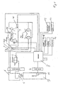
- ein Block-Diagramm des hydrostatischen Getriebes und
- Fig. 2
- ein Diagramm der Hydromotorverstellung.
- Fig. 1:
Eine Antriebsmaschine 1 treibt eine Hydropumpe 2 an, welche Druckflüssigkeit aus einem Druckflüssigkeitsreservoir 3 entnimmt. Die Hydropumpe 2 ist über ein Hauptsteüerventil 4 mit dem Hydromotor 5 verbunden. Der Hydromotor 5 ist über zwei Arbeitsleitungen 6 mit dem Hauptsteuerventil 4 verbunden, welches, je nach Auslenkung, eine Arbeitsleitung mit der Hydropumpe 2 und eine Arbeitsleitung mit dem Druckflüssigkeitsreservoir 3 verbindet. Der Hydromotor 5 ist ein steuerdruckabhängig verstellbarer Hydromotor mit überlagerter Druckregelung, welcher ein nicht dargestelltes Bremsventil und sekundär, nicht dargestellte, wirkende Druckbegrenzungsventile aufweist. Dem hydraulischen Motor 5 ist ein schaltbares Untersetzungsgetriebe 7 nachgeschaltet angeordnet, welches mit den Fahrzeugrädern in Verbindung steht. Eine elektronische Steuereinheit 8 erhält über einen Sensor 9 die Auslenkung des Hauptsteuerventils 4, welches direkt mit einem Fahrpedal 10 in Verbindung steht. Über einen Drehzahlsensor 11 erhält die elektronische Steuereinheit 8 das Abtriebsdrehzahlsignal, welches einer Fahrgeschwindigkeit des Fahrzeugs entspricht. Zusätzlich ist die elektronische Steuereinheit 8 mit einem Verzögerungswählschalter 12, mit welchem beispielsweise drei Verzögerungsstufen "Weich", "Mittel", "Hart" gewählt werden können, sowie einem Kriechgangschalter 13, bei dessen Aktivierung die elektronische Steuereinheit 8 das Schluckvolumen des Hydromotors 5 auf sein maximales-Schluckvolumen einstellt, einem Bremsschalter 14, bei dessen Betätigung die elektronische Steuereinheit 8 automatisch auf die Verzögerung "Hart" eingestellt wird, sowie einer Eingabemöglichkeit 15, bei welcher Fahrzeugdaten definiert werden, verbunden. Ein Temperatursensor 16 ermittelt die Temperatur im Druckflüssigkeitsreservoir 3, wodurch die elektronische Steuereinheit 8 in Abhängigkeit von dieser Temperatur das Schluckvolumen des Hydromotors 5 einstellt. Über einen Drehzahlsensor 16 und einen Sensor 17 ermittelt die elektronische Steuereinheit 8 den Förderstrom der Hydropumpe 2. - Die elektronische Steuereinheit und das Hydromotor-Steuerventil können auch im Unterwagen angeordnet sein.
- Somit besteht die Möglichkeit, den Hydromotor 5 so zu verstellen, dass die Geschwindigkeit des Fahrzeugs der Wunschgeschwindigkeit, welche vom Fahrer über das Fahrpedal eingestellt wird, erreicht. Ebenso verzögert das Fahrzeug, unabhängig von der geschalteten Untersetzung des Untersetzungsgetriebes 7, gleichmäßig mit einer von dem Fahrer definierbaren Verzögerung "Hart", "Mittel" oder "Weich".
- Fig. 2:
Im Diagramm ist dargestellt, wie die Geschwindigkeitsregelung stattfindet. Der Fahrerwunsch und somit die Soll-Fahrgeschwindigkeit wird aus der Fahrpedalposition oder der Stellung des Hauptsteuerventils oder mit Hilfe eines Drucksensors im Steuerdruck des Fahrpedals und der Verbrennungsmotordrehzahl ermittelt. Auf der Ordinate ist die Differenz zwischen Ist- und Soll-Geschwindigkeit aufgetragen. Auf der Abszisse ist das Schluckvolumen des Hydromotors aufgetragen. In diesem Kennfeld sind, abhängig von der aktuellen Beschleunigung, welche aus der gemessenen Hydromotor- und Abtriebsdrehzahl mit der aktuellen Übersetzung des Untersetzungsgetriebes errechnet wird, verschiedene Kennlinien eingetragen. Der Kleinstwert des Hydromotor-Scluckvolumens, beispielsweise 54,50 cm3/U, entspricht dem theoretisch notwendigen, minimalen Schluckvolumen, um bei maximaler Verbrennungsmotordrehzahl und vollständig betätigtem Fahrpedal die maximale Fahrgeschwindigkeit, welche abhängig von der Geschwindigkeitsklasse des Fahrzeugs, beispielsweise 20,25 km/h oder 34,00 km/h, ist, zu erreichen. Der Größtwert des Hydromotor-Schluckvolumens ist entweder das maximale Schluckvolumen des verwendeten Hydromotors bzw. ein reduzierter Wert, wenn dabei das maximal zulässige Antriebsdrehmoment im Schubbetrieb für das Getriebe überschritten würde. Ist die aktuelle Fahrzeugbeschleunigung positiv und sehr hoch, beispielsweise a = 2, was der Linie 18 entspricht und beispielsweise während einer Beschleunigungsfahrt in eine Gefällstrecke auftritt, wird das Hydromotor-Schluckvolumen q_HM bereits 4 km/h vor der Soll-Geschwindigkeit vergrößert, damit einem Übertouren vorgehalten werden kann. Ist die aktuelle Fahrzeugbeschleunigung nahezu Null, a = 0, was der Linie 19 entspricht und beispielsweise in der Ebene auftritt, wird das Hydromotor-Schluckvolumen q_HM bis zur Erreichung der Soll-Geschwindigkeit nicht verändert. Steigt die Geschwindigkeit v_Ist über die Soll-Geschwindigkeit v_Soll, wird das Hydromotor-Schluckvolumen q_HM anfänglich sehr geringfügig erhöht und bei weiter steigender Ist-Geschwindigkeit v_Ist exponentiell erhöht. Dies verhindert Schwingungen beim Fahren in der Ebene. Ist die aktuelle Fahrzeugbeschleunigung negativ, beispielsweise a = -2, was in der Linie 20 dargestellt ist, so bleibt das Hydromotor-Schluckvolumen q_HM bis zu einer Geschwindigkeitsüberschreitung von beispielsweise 4 km/h unverändert und steigt bei weiter steigender Ist-Geschwindigkeit v_Ist bis auf den maximalen Wert an. Zwischenwerte können interpoliert werden. - Bei Verwendung eines nachgeschalteten Untersetzungsgetriebes mit zwei Gängen besteht folgende Möglichkeit: Für den ersten Gang existiert ein einziges Kennfeld für alle Fahrzeuggeschwindigkeitsklassen, beispielsweise 20 km/h, 25 km/h, 34 km/h Maximalgeschwindigkeit, d. h., im ersten Gang ist die maximale Arbeitsgeschwindigkeit gleich. Für den zweiten Gang existiert für jede Geschwindigkeitsklasse ein Kennfeld. Dieses Kennfeld oder die Funktion ist in der elektronischen Steuerung abgelegt.
- Der in Fig. 2 enthaltene kleinste Wert für das Hydromotor-Schluckvolumen q_HM, welches so klein ist, dass die maximale Fahrzeuggeschwindigkeit v_max in jedem Fall auch bei unterschiedlichen Toleranzen erreicht werden kann, wird theoretisch errechnet (= f(Q_Fahren, n_soll)). Somit ist es nicht notwendig, im Fahrzeug zu kalibrieren.
Durch eine adaptive Regelung wird das tatsächliche, minimal notwendige Hydromotor-Schluckvolumen q_HM ermittelt. In stationären Betriebszuständen, beispielsweise wenn der Verbrennungsmotor bei seiner maximalen Drehzahl betrieben wird, das Fahrpedal voll betätigt und/oder die aktuelle Beschleunigung nahezu Null und die Ist-Geschwindigkeit größer der Soll-Geschwindigkeit ist, wird der kleinste Hydromotor-schluckvolumenwert q_HM-Wert im Kennfeld so lange vergrößert, bis die Regelabweichung nahezu Null.wird. Durch diese adaptive Regelung werden vorhandene Toleranzen, wie beispielsweise die Einstellung der Pumpe, Einstellung der Mengenregelung im Hauptschieber, Kennung des Steuerdruckkolbenhubs des Hauptschiebers, Kennung der Fahrpedalposition-Steuerdruck, Kennung Steuerstrom-Steuerdruck vom HDD-Control und Kennung Steuerdruck-q_HM im Hydromotor, ausgeglichen.
Der Wert vom Schluckvolumen des Hydromotors q_HM, den die adaptive Regelung ermittelt, wird in einem nicht flüchtigen Speicherbereich der elektronischen Steuereinheit abgelegt. -
- 1
- Antriebsmaschine
- 2
- Hydropumpe
- 3
- Druckflüssigkeitsreservoir
- 4
- Hauptsteuerventil
- 5
- Hydromotor
- 6
- Arbeitsleitung
- 7
- Untersetzungsgetriebe
- 8
- elektronische Steuereinheit
- 9
- Sensor
- 10
- Fahrpedal
- 11
- Drehzahlsensor
- 12
- Verzögerungswählschalter
- 13
- Kriechgangschalter
- 14
- Bremsschalter
- 15
- Eingabemöglichkeit
- 16
- Drehzahlsensor
- 17
- Sensor
- 18
- Linie
- 19
- Linie
- 20
- Linie
Claims (10)
- Hydrostatisches Getriebe für ein mobiles Fahrzeug mit mindestens einer Hydropumpe (2) und wenigstens einem, in seinem Schluckvolumen verstellbaren Hydromotor (5), welcher an zwei Arbeitsleitungen (6) angeschlossen ist, wobei die Hydropumpe (2) Druckmittel aus einem Druckmittelreservoir (3) entnimmt, und über wenigstens eine Arbeitsleitung (6) dem Hydromotor (5) zuführt, und einem Bremsventil, welches es ermöglicht, einen Druckmittelstrom, welcher den Hydromotor (5) verläßt, zu begrenzen, dadurch gekennzeichnet, dass ein Sensor (11) eine Fahrzeuggeschwindigkeit bzw. eine Abtriebsdrehzahl, welche dieser Fahrzeuggeschwindigkeit entspricht, ermittelt, und einer elektronischen Steuereinheit (8) zuführt, welche in Abhängigkeit eines Geschwindigkeitswunsches eine diesem entsprechende Fahrzeuggeschwindigkeit bzw. Abtriebsdrehzahl errechnet und das Schluckvolumen des Hydromotors (5) so verstellt, dass die vom Sensor (11) ermittelte Fahrzeuggeschwindigkeit bzw. Abtriebsdrehzahl der errechneten Fahrzeuggeschwindigkeit bzw. Abtriebsdrehzahl nahezu entspricht, wobei bei einem Bremsvorgang, der Hydromotor so verstellt wird, dass ein zuvor definierter Verzögerungsgrad erreicht wird.
- Hydrostatisches Getriebe nach Anspruch 1, dadurch gekennzeichnet, dass die elektronische Steuerung (8) den Hydromotor (5) so verstellt, dass die Verzögerung des Fahrzeugs einen konstanten, zuvor definierten Wert annimmt.
- Hydrostatisches Getriebe nach Anspruch 2, dadurch gekennzeichnet, dass der zuvor definierte Wert veränderbar ist.
- Hydrostatisches Getriebe nach Anspruch 2, dadurch gekennzeichnet, dass die Verzögerung anhand eines zuvor definierten Kennfeldes geregelt wird.
- Hydrostatisches Getriebe nach Anspruch 1, dadurch gekennzeichnet, dass durch Betätigen einer Betriebsbremse (14) des Fahrzeugs der Hydromotor (5) automatisch so verstellt wird, dass die maximale, zuvor definierte Verzögerung erreicht wird.
- Hydrostatisches Getriebe nach Anspruch 1, dadurch gekennzeichnet, dass dem Hydromotor (5) ein schaltbares Untersetzungsgetriebe (7) nachgeschaltet angeordnet ist und die elektronische Steuerung (8) die geschaltete Übersetzung berücksichtigt.
- Hydrostatisches Getriebe nach Anspruch 1, dadurch gekennzeichnet , dass ein Steuersignal, mittels welchem der Hydromotor (5) verstellt wird, entsprechend angepaßt wird, wenn sich die aktuelle Geschwindigkeit der Soll-Geschwindigkeit annähert.
- Hydrostatisches Getriebe nach Anspruch 1, dadurch gekennzeichnet, dass durch ein manuell betätigbares Signal (13) die elektronische Steuerung (8) den Hydromotor (5) auf seinem maximalen Schluckvolumen hält.
- Hydrostatisches Getriebe nach Anspruch 1, dadurch gekennzeichnet, dass ein Sensor (16) die Temperatur der Hydraulikflüssigkeit ermittelt und die elektronische Steuerung (8) den Hydromotor (5) so verstellt, dass eine definierte Temperatur nicht überschritten wird.
- Hydrostatisches Getriebe nach Anspruch 1, dadurch gekennzeichnet , dass ein minimal notwendiges Schluckvolumen des Hydromotors von der elektronischen Steuereinheit errechnet wird, das tatsächliche minimale Schluckvolumen mit diesem verglichen wird und anschließend eine adaptive Regelung das tatsächlich notwendige Schluckvolumen des Hydromotors ermittelt und die abgelegten Werte so lange verändert, bis eine Regelabweichung nahezu Null wird.
Applications Claiming Priority (3)
| Application Number | Priority Date | Filing Date | Title |
|---|---|---|---|
| DE10303206 | 2003-01-28 | ||
| DE10303206A DE10303206A1 (de) | 2003-01-28 | 2003-01-28 | Hydrostatisches Getriebe |
| PCT/EP2004/000492 WO2004068005A2 (de) | 2003-01-28 | 2004-01-22 | Hydrostatisches getriebe |
Publications (2)
| Publication Number | Publication Date |
|---|---|
| EP1588078A2 EP1588078A2 (de) | 2005-10-26 |
| EP1588078B1 true EP1588078B1 (de) | 2007-08-29 |
Family
ID=32602987
Family Applications (1)
| Application Number | Title | Priority Date | Filing Date |
|---|---|---|---|
| EP04704185A Expired - Lifetime EP1588078B1 (de) | 2003-01-28 | 2004-01-22 | Hydrostatisches getriebe |
Country Status (8)
| Country | Link |
|---|---|
| US (1) | US7841442B2 (de) |
| EP (1) | EP1588078B1 (de) |
| JP (1) | JP2006516708A (de) |
| KR (1) | KR101009184B1 (de) |
| CN (1) | CN100417845C (de) |
| AT (1) | ATE371824T1 (de) |
| DE (2) | DE10303206A1 (de) |
| WO (1) | WO2004068005A2 (de) |
Families Citing this family (26)
| Publication number | Priority date | Publication date | Assignee | Title |
|---|---|---|---|---|
| JP5264091B2 (ja) * | 2007-03-09 | 2013-08-14 | カヤバ工業株式会社 | メカニカルスロットル車両のオートモーティブ制御装置 |
| US7798277B2 (en) | 2007-05-31 | 2010-09-21 | Caterpillar Inc | Machine retarder |
| ITBO20080577A1 (it) * | 2008-09-19 | 2010-03-20 | Cnh Italia Spa | Veicolo agricolo a trasmissione variabile continua |
| CN102529967A (zh) * | 2010-12-29 | 2012-07-04 | 天津市友达机电液成套设备有限公司 | 轮式车辆液压行走马达限速保护方法及其装置 |
| US9096230B2 (en) * | 2011-11-01 | 2015-08-04 | Caterpillar Paving Products Inc. | Hystat drive system having coasting functionality |
| US9097341B2 (en) * | 2012-01-26 | 2015-08-04 | Caterpillar Inc. | Brake system having a brake capacity test mode for a machine having a hydrostatic drivetrain |
| JP5113946B1 (ja) * | 2012-03-27 | 2013-01-09 | 株式会社小松製作所 | 作業車両及び作業車両の制御方法 |
| DE102012020632A1 (de) * | 2012-10-19 | 2014-04-24 | Robert Bosch Gmbh | Verfahren und Steuergerät zum Ansteuern einer Hydraulikmaschine |
| CN102922993B (zh) * | 2012-10-31 | 2015-05-20 | 吴亚利 | 汽车电控液力独立轴端驱动系统控制装置 |
| ITMO20120298A1 (it) * | 2012-11-29 | 2014-05-30 | Cnh Italia Spa | Un metodo per stimare la coppia a valle della trasmissione di un veicolo. |
| DE102012221943A1 (de) * | 2012-11-30 | 2014-06-05 | Zf Friedrichshafen Ag | Vorrichtung, Verfahren und Computerprogramm zur Einstellung eines hydrostatischen Antriebs, Antrieb und Bau- oder Landmaschine |
| US9347554B2 (en) * | 2013-03-14 | 2016-05-24 | Caterpillar Inc. | Hydrostatic drive system |
| CA2809495C (en) * | 2013-03-15 | 2014-06-03 | Westport Power Inc. | Temperature control of a fluid discharged from a heat exchanger |
| CN104141780B (zh) * | 2013-05-10 | 2018-04-27 | 林德液压两合公司 | 用于对传动装置的换挡变速器进行换挡的方法 |
| US9512918B2 (en) * | 2013-06-14 | 2016-12-06 | Danfoss Power Solutions Inc. | Speed control system for a hydrostatic transmission |
| DE102013213896A1 (de) * | 2013-07-16 | 2015-01-22 | Robert Bosch Gmbh | Verfahren und System zum Regeln eines Drucks |
| DE102014206123B4 (de) * | 2014-04-01 | 2023-12-07 | Robert Bosch Gmbh | Hydrostatischer Fahrantrieb in geschlossenem hydraulischen Kreis und Verfahren zur Steuerung des hydrostatischen Fahrantriebs |
| JP6648136B2 (ja) * | 2015-07-13 | 2020-02-14 | 住友建機株式会社 | アスファルトフィニッシャ |
| DE102016221126A1 (de) * | 2016-10-26 | 2018-04-26 | Zf Friedrichshafen Ag | Verfahren zum Durchführen eines Kaltstarts |
| DE102016223873A1 (de) | 2016-11-30 | 2018-05-30 | Zf Friedrichshafen Ag | Verfahren zum Steuern eines stufenlosen Getriebes für ein Fahrzeug |
| CN106945520B (zh) * | 2017-04-13 | 2019-01-25 | 威海市华塔建筑机械有限公司 | 静液传动车辆油门减小及滑行时的速度控制方法 |
| US10393261B2 (en) * | 2017-12-06 | 2019-08-27 | Cnh Industrial America Llc | High ambient temperature propulsion speed control of a self-propelled agricultural product applicator |
| DE102018206908A1 (de) | 2018-05-04 | 2019-11-07 | Robert Bosch Gmbh | Elektronisches Überwachungssystem für hydrostatische Fahrantriebe und Fahrantrieb mit elektronischem Überwachungssystem |
| CN109249801A (zh) * | 2018-09-22 | 2019-01-22 | 江苏悦达专用车有限公司 | 一种静液压低速行走系统 |
| CN109630494B (zh) * | 2019-02-11 | 2024-07-26 | 西安汇鑫传动控制有限责任公司 | 基于双角度感应的径向柱塞马达转速测量控制系统及方法 |
| DE102019210644A1 (de) | 2019-07-18 | 2021-01-21 | Wirtgen Gmbh | Selbstfahrende Baumaschine und Verfahren zum Bearbeiten von Bodenbelägen |
Family Cites Families (26)
| Publication number | Priority date | Publication date | Assignee | Title |
|---|---|---|---|---|
| DE2740024A1 (de) * | 1977-09-06 | 1978-09-14 | Losenhausen Maschinenbau Ag | Hydrostatischer fahrantrieb fuer baumaschinen |
| EP0377953B1 (de) * | 1988-11-18 | 1994-12-14 | Honda Giken Kogyo Kabushiki Kaisha | Steuerungssystem für ein automatisches Fahrzeuggetriebe |
| JPH03186663A (ja) * | 1989-12-14 | 1991-08-14 | Nippon Air Brake Co Ltd | 油圧モータの制御回路 |
| JPH04258570A (ja) | 1991-02-14 | 1992-09-14 | Kubota Corp | 作業車 |
| DE4129667A1 (de) | 1991-09-06 | 1993-03-18 | Hydromatik Gmbh | Hydrostatisches getriebe mit offenem kreislauf und bremsventil |
| JP3193431B2 (ja) * | 1992-01-10 | 2001-07-30 | 本田技研工業株式会社 | 油圧装置の補給油供給制御装置 |
| US5678462A (en) * | 1992-03-04 | 1997-10-21 | Hydromatik Gmbh | Hydrostatic travelling drive |
| DE4234826C1 (de) * | 1992-10-15 | 1993-10-28 | Hydromatik Gmbh | Hydrostatisches Getriebe |
| JP3402639B2 (ja) | 1992-12-19 | 2003-05-06 | マツダ株式会社 | 車両の駆動装置 |
| DE4330391B4 (de) * | 1993-03-31 | 2008-02-07 | Robert Bosch Gmbh | Verfahren zum Betrieb eines Fahrzeugs mit kontinuierlich verstellbarem Getriebe |
| DE4312716A1 (de) | 1993-04-20 | 1994-10-27 | Zahnradfabrik Friedrichshafen | Doppelt wirkendes Bremsventil |
| US5435131A (en) | 1994-04-11 | 1995-07-25 | Caterpillar Inc. | Adaptive overspeed control for a hydrostatic transmission |
| DE19505691C2 (de) * | 1995-02-20 | 1998-11-26 | Sauer Sundstrand Gmbh & Co | Hydrostatisches Getriebe mit einem hubvolumenverstellbaren Hydromotor |
| US5575735A (en) * | 1995-04-06 | 1996-11-19 | Caterpillar Inc. | Integrated power transmitting system |
| DE19524669C2 (de) | 1995-07-06 | 1999-03-18 | Sauer Sundstrand Gmbh & Co | Steuer- und Regeleinrichtung zur Inbetriebnahme eines Fahrzeuges mit automotivem hydrostatischem Getriebe |
| US6135231A (en) * | 1998-04-27 | 2000-10-24 | Sauer Inc. | Method and means for providing a steer-assist and anti-spin system for hydrostatically propelled vehicles |
| JPH11351384A (ja) * | 1998-06-12 | 1999-12-24 | Daikin Ind Ltd | 車両の動力回収運転時におけるハイドロメカニカルトランスミッションの入力軸回転数制御方法 |
| JP2000193086A (ja) * | 1998-12-28 | 2000-07-14 | Hitachi Constr Mach Co Ltd | 無段変速油圧走行駆動装置 |
| US6138069A (en) | 1999-05-24 | 2000-10-24 | Textron Inc. | Utility vehicle with work-performing attachment |
| US6260440B1 (en) * | 1999-12-17 | 2001-07-17 | Caterpillar Inc. | Method and apparatus for shifting ranges in a continuously variable transmission |
| JP2001280465A (ja) * | 2000-03-31 | 2001-10-10 | Honda Motor Co Ltd | 無段変速機の制御方法 |
| US20040074691A1 (en) | 2000-12-11 | 2004-04-22 | Joel Bombardier | Virtual braking system for hydrostatically driven vehicle |
| DE60138652D1 (de) | 2001-01-19 | 2009-06-18 | Hitachi Construction Machinery | Hydraulikmotor-störungsdetektor und hydraulisch angetriebenes fahrzeug |
| FR2849142B1 (fr) * | 2002-12-20 | 2007-01-26 | Poclain Hydraulics Ind | Systeme de freinage pour un vehicule entraine par au moins un moteur hydraulique alimente en circuit ferme |
| US6916697B2 (en) * | 2003-10-08 | 2005-07-12 | Lam Research Corporation | Etch back process using nitrous oxide |
| JP4258570B2 (ja) | 2008-02-08 | 2009-04-30 | 住友電気工業株式会社 | 風速レーダ |
-
2003
- 2003-01-28 DE DE10303206A patent/DE10303206A1/de not_active Withdrawn
-
2004
- 2004-01-22 US US10/543,725 patent/US7841442B2/en not_active Expired - Fee Related
- 2004-01-22 KR KR1020057013824A patent/KR101009184B1/ko active IP Right Grant
- 2004-01-22 JP JP2006501574A patent/JP2006516708A/ja active Pending
- 2004-01-22 CN CNB2004800030463A patent/CN100417845C/zh not_active Expired - Fee Related
- 2004-01-22 AT AT04704185T patent/ATE371824T1/de not_active IP Right Cessation
- 2004-01-22 WO PCT/EP2004/000492 patent/WO2004068005A2/de active IP Right Grant
- 2004-01-22 EP EP04704185A patent/EP1588078B1/de not_active Expired - Lifetime
- 2004-01-22 DE DE502004004806T patent/DE502004004806D1/de not_active Expired - Lifetime
Also Published As
| Publication number | Publication date |
|---|---|
| EP1588078A2 (de) | 2005-10-26 |
| JP2006516708A (ja) | 2006-07-06 |
| CN100417845C (zh) | 2008-09-10 |
| US7841442B2 (en) | 2010-11-30 |
| DE502004004806D1 (de) | 2007-10-11 |
| CN1745262A (zh) | 2006-03-08 |
| KR20050098266A (ko) | 2005-10-11 |
| DE10303206A1 (de) | 2004-07-29 |
| ATE371824T1 (de) | 2007-09-15 |
| WO2004068005A3 (de) | 2004-12-29 |
| US20060230920A1 (en) | 2006-10-19 |
| WO2004068005A2 (de) | 2004-08-12 |
| KR101009184B1 (ko) | 2011-01-18 |
Similar Documents
| Publication | Publication Date | Title |
|---|---|---|
| EP1588078B1 (de) | Hydrostatisches getriebe | |
| DE69529082T2 (de) | Drehzahländerer einer hydraulischen antriebsvorrichtung und steuerungsverfahren dafür | |
| EP0339202B1 (de) | Antriebseinrichtung für Maschinen und Fahrzeuge | |
| DE112005001920B4 (de) | Laststeuervorrichtung für den Motor eines Arbeitsfahrzeugs | |
| DE60215889T2 (de) | Geschwindigkeitsregelung eines Fahrzeugs | |
| DE10037676C1 (de) | Vorrichtung zur Regelung eines Antriebssystems für ein Flurförderzeug | |
| EP2050961B1 (de) | Hydraulisches Antriebssystem | |
| DE112008000724T5 (de) | Steuerung eines Fahrzeugs mit hydrostatischem, stufenlos variablem Getriebe | |
| DE112007002112T5 (de) | Baufahrzeug | |
| DE102007003800B3 (de) | Verfahren zur Regelung eines hydrostatischen Antriebssystems | |
| DE112012004575T5 (de) | Hystat-Antriebssystem mit Ausrollfunktionalität | |
| DE102007041087B4 (de) | Verfahren und System zur dynamischen Steuerung einer Drehmomentwandlerkupplung | |
| DE4301591A1 (de) | ||
| EP3587795A1 (de) | Hydrostatischer fahrantrieb mit druckabschneidung und verfahren zum kalibrieren der druckabschneidung | |
| DE60214953T2 (de) | Kontrollsystem für eine vorwärts-rückwärts Getriebeeinheit | |
| DE102005037032A1 (de) | Die Bremsen betätigendes Getriebesteuersystem | |
| EP1608526B1 (de) | Antriebsstrang zum antrieb eines mobil-fahrzeugs | |
| DE10360479A1 (de) | Fluiddrucksteuervorrichtung für einen Sperrmechanismus | |
| DE112012004582T5 (de) | Hystat-Antriebssystem mit Brennkraftmaschinendrehzahlsteuerung | |
| DE19830950A1 (de) | Verfahren und Vorrichtung zur Betätigung einer Kraftfahrzeug-Kupplungsvorrichtung | |
| DE102013113205A1 (de) | Verfahren zur Grenzlastregelung eines hydrostatischen Antriebssystems | |
| DE19823766B4 (de) | Vorrichtung und Verfahren zur Steuerung des von einer automatisierten Kupplung übertragbaren Drehmomentes | |
| DE10154651C1 (de) | Kettenfahrzeug mit einem Antriebssystem | |
| WO2008000382A1 (de) | Verfahren zur steuerung eines übersetzungsverhältnisses | |
| EP1608525B1 (de) | Verfahren zum betrieb eines antriebsstrangs zum antrieb eines mobil-fahrzeugs |
Legal Events
| Date | Code | Title | Description |
|---|---|---|---|
| PUAI | Public reference made under article 153(3) epc to a published international application that has entered the european phase |
Free format text: ORIGINAL CODE: 0009012 |
|
| 17P | Request for examination filed |
Effective date: 20050714 |
|
| AK | Designated contracting states |
Kind code of ref document: A2 Designated state(s): AT BE BG CH CY CZ DE DK EE ES FI FR GB GR HU IE IT LI LU MC NL PT RO SE SI SK TR |
|
| AX | Request for extension of the european patent |
Extension state: AL LT LV MK |
|
| DAX | Request for extension of the european patent (deleted) | ||
| GRAP | Despatch of communication of intention to grant a patent |
Free format text: ORIGINAL CODE: EPIDOSNIGR1 |
|
| GRAS | Grant fee paid |
Free format text: ORIGINAL CODE: EPIDOSNIGR3 |
|
| GRAA | (expected) grant |
Free format text: ORIGINAL CODE: 0009210 |
|
| AK | Designated contracting states |
Kind code of ref document: B1 Designated state(s): AT BE BG CH CY CZ DE DK EE ES FI FR GB GR HU IE IT LI LU MC NL PT RO SE SI SK TR |
|
| REG | Reference to a national code |
Ref country code: GB Ref legal event code: FG4D Free format text: NOT ENGLISH |
|
| GBT | Gb: translation of ep patent filed (gb section 77(6)(a)/1977) |
Effective date: 20070829 |
|
| REG | Reference to a national code |
Ref country code: CH Ref legal event code: EP |
|
| REG | Reference to a national code |
Ref country code: IE Ref legal event code: FG4D Free format text: LANGUAGE OF EP DOCUMENT: GERMAN |
|
| REF | Corresponds to: |
Ref document number: 502004004806 Country of ref document: DE Date of ref document: 20071011 Kind code of ref document: P |
|
| ET | Fr: translation filed | ||
| REG | Reference to a national code |
Ref country code: SE Ref legal event code: TRGR |
|
| PG25 | Lapsed in a contracting state [announced via postgrant information from national office to epo] |
Ref country code: NL Free format text: LAPSE BECAUSE OF FAILURE TO SUBMIT A TRANSLATION OF THE DESCRIPTION OR TO PAY THE FEE WITHIN THE PRESCRIBED TIME-LIMIT Effective date: 20070829 Ref country code: FI Free format text: LAPSE BECAUSE OF FAILURE TO SUBMIT A TRANSLATION OF THE DESCRIPTION OR TO PAY THE FEE WITHIN THE PRESCRIBED TIME-LIMIT Effective date: 20070829 Ref country code: ES Free format text: LAPSE BECAUSE OF FAILURE TO SUBMIT A TRANSLATION OF THE DESCRIPTION OR TO PAY THE FEE WITHIN THE PRESCRIBED TIME-LIMIT Effective date: 20071210 |
|
| NLV1 | Nl: lapsed or annulled due to failure to fulfill the requirements of art. 29p and 29m of the patents act | ||
| REG | Reference to a national code |
Ref country code: IE Ref legal event code: FD4D |
|
| PG25 | Lapsed in a contracting state [announced via postgrant information from national office to epo] |
Ref country code: GR Free format text: LAPSE BECAUSE OF FAILURE TO SUBMIT A TRANSLATION OF THE DESCRIPTION OR TO PAY THE FEE WITHIN THE PRESCRIBED TIME-LIMIT Effective date: 20071130 Ref country code: DK Free format text: LAPSE BECAUSE OF FAILURE TO SUBMIT A TRANSLATION OF THE DESCRIPTION OR TO PAY THE FEE WITHIN THE PRESCRIBED TIME-LIMIT Effective date: 20070829 |
|
| PG25 | Lapsed in a contracting state [announced via postgrant information from national office to epo] |
Ref country code: SK Free format text: LAPSE BECAUSE OF FAILURE TO SUBMIT A TRANSLATION OF THE DESCRIPTION OR TO PAY THE FEE WITHIN THE PRESCRIBED TIME-LIMIT Effective date: 20070829 Ref country code: PT Free format text: LAPSE BECAUSE OF FAILURE TO SUBMIT A TRANSLATION OF THE DESCRIPTION OR TO PAY THE FEE WITHIN THE PRESCRIBED TIME-LIMIT Effective date: 20080129 Ref country code: IE Free format text: LAPSE BECAUSE OF FAILURE TO SUBMIT A TRANSLATION OF THE DESCRIPTION OR TO PAY THE FEE WITHIN THE PRESCRIBED TIME-LIMIT Effective date: 20070829 Ref country code: CZ Free format text: LAPSE BECAUSE OF FAILURE TO SUBMIT A TRANSLATION OF THE DESCRIPTION OR TO PAY THE FEE WITHIN THE PRESCRIBED TIME-LIMIT Effective date: 20070829 |
|
| PG25 | Lapsed in a contracting state [announced via postgrant information from national office to epo] |
Ref country code: RO Free format text: LAPSE BECAUSE OF FAILURE TO SUBMIT A TRANSLATION OF THE DESCRIPTION OR TO PAY THE FEE WITHIN THE PRESCRIBED TIME-LIMIT Effective date: 20070829 |
|
| PLBE | No opposition filed within time limit |
Free format text: ORIGINAL CODE: 0009261 |
|
| STAA | Information on the status of an ep patent application or granted ep patent |
Free format text: STATUS: NO OPPOSITION FILED WITHIN TIME LIMIT |
|
| 26N | No opposition filed |
Effective date: 20080530 |
|
| PG25 | Lapsed in a contracting state [announced via postgrant information from national office to epo] |
Ref country code: MC Free format text: LAPSE BECAUSE OF NON-PAYMENT OF DUE FEES Effective date: 20080131 |
|
| REG | Reference to a national code |
Ref country code: CH Ref legal event code: PL |
|
| PG25 | Lapsed in a contracting state [announced via postgrant information from national office to epo] |
Ref country code: LI Free format text: LAPSE BECAUSE OF NON-PAYMENT OF DUE FEES Effective date: 20080131 Ref country code: CH Free format text: LAPSE BECAUSE OF NON-PAYMENT OF DUE FEES Effective date: 20080131 |
|
| PG25 | Lapsed in a contracting state [announced via postgrant information from national office to epo] |
Ref country code: EE Free format text: LAPSE BECAUSE OF FAILURE TO SUBMIT A TRANSLATION OF THE DESCRIPTION OR TO PAY THE FEE WITHIN THE PRESCRIBED TIME-LIMIT Effective date: 20070829 |
|
| PG25 | Lapsed in a contracting state [announced via postgrant information from national office to epo] |
Ref country code: AT Free format text: LAPSE BECAUSE OF NON-PAYMENT OF DUE FEES Effective date: 20080122 |
|
| PG25 | Lapsed in a contracting state [announced via postgrant information from national office to epo] |
Ref country code: SI Free format text: LAPSE BECAUSE OF FAILURE TO SUBMIT A TRANSLATION OF THE DESCRIPTION OR TO PAY THE FEE WITHIN THE PRESCRIBED TIME-LIMIT Effective date: 20070829 |
|
| PG25 | Lapsed in a contracting state [announced via postgrant information from national office to epo] |
Ref country code: CY Free format text: LAPSE BECAUSE OF FAILURE TO SUBMIT A TRANSLATION OF THE DESCRIPTION OR TO PAY THE FEE WITHIN THE PRESCRIBED TIME-LIMIT Effective date: 20070829 |
|
| PG25 | Lapsed in a contracting state [announced via postgrant information from national office to epo] |
Ref country code: BG Free format text: LAPSE BECAUSE OF FAILURE TO SUBMIT A TRANSLATION OF THE DESCRIPTION OR TO PAY THE FEE WITHIN THE PRESCRIBED TIME-LIMIT Effective date: 20071129 |
|
| PGFP | Annual fee paid to national office [announced via postgrant information from national office to epo] |
Ref country code: BE Payment date: 20100125 Year of fee payment: 7 |
|
| PG25 | Lapsed in a contracting state [announced via postgrant information from national office to epo] |
Ref country code: LU Free format text: LAPSE BECAUSE OF NON-PAYMENT OF DUE FEES Effective date: 20080122 Ref country code: HU Free format text: LAPSE BECAUSE OF FAILURE TO SUBMIT A TRANSLATION OF THE DESCRIPTION OR TO PAY THE FEE WITHIN THE PRESCRIBED TIME-LIMIT Effective date: 20080301 |
|
| PG25 | Lapsed in a contracting state [announced via postgrant information from national office to epo] |
Ref country code: TR Free format text: LAPSE BECAUSE OF FAILURE TO SUBMIT A TRANSLATION OF THE DESCRIPTION OR TO PAY THE FEE WITHIN THE PRESCRIBED TIME-LIMIT Effective date: 20070829 |
|
| BERE | Be: lapsed |
Owner name: ZF FRIEDRICHSHAFEN A.G. Effective date: 20110131 |
|
| PG25 | Lapsed in a contracting state [announced via postgrant information from national office to epo] |
Ref country code: BE Free format text: LAPSE BECAUSE OF NON-PAYMENT OF DUE FEES Effective date: 20110131 |
|
| PGFP | Annual fee paid to national office [announced via postgrant information from national office to epo] |
Ref country code: IT Payment date: 20150116 Year of fee payment: 12 |
|
| PGFP | Annual fee paid to national office [announced via postgrant information from national office to epo] |
Ref country code: SE Payment date: 20150113 Year of fee payment: 12 |
|
| REG | Reference to a national code |
Ref country code: FR Ref legal event code: PLFP Year of fee payment: 13 |
|
| PG25 | Lapsed in a contracting state [announced via postgrant information from national office to epo] |
Ref country code: SE Free format text: LAPSE BECAUSE OF NON-PAYMENT OF DUE FEES Effective date: 20160123 |
|
| REG | Reference to a national code |
Ref country code: FR Ref legal event code: PLFP Year of fee payment: 14 |
|
| PG25 | Lapsed in a contracting state [announced via postgrant information from national office to epo] |
Ref country code: IT Free format text: LAPSE BECAUSE OF NON-PAYMENT OF DUE FEES Effective date: 20160122 |
|
| REG | Reference to a national code |
Ref country code: FR Ref legal event code: PLFP Year of fee payment: 15 |
|
| PGFP | Annual fee paid to national office [announced via postgrant information from national office to epo] |
Ref country code: FR Payment date: 20191216 Year of fee payment: 17 |
|
| PGFP | Annual fee paid to national office [announced via postgrant information from national office to epo] |
Ref country code: GB Payment date: 20200115 Year of fee payment: 17 |
|
| GBPC | Gb: european patent ceased through non-payment of renewal fee |
Effective date: 20210122 |
|
| PG25 | Lapsed in a contracting state [announced via postgrant information from national office to epo] |
Ref country code: FR Free format text: LAPSE BECAUSE OF NON-PAYMENT OF DUE FEES Effective date: 20210131 |
|
| PG25 | Lapsed in a contracting state [announced via postgrant information from national office to epo] |
Ref country code: GB Free format text: LAPSE BECAUSE OF NON-PAYMENT OF DUE FEES Effective date: 20210122 |
|
| PGFP | Annual fee paid to national office [announced via postgrant information from national office to epo] |
Ref country code: DE Payment date: 20221130 Year of fee payment: 20 |
|
| P01 | Opt-out of the competence of the unified patent court (upc) registered |
Effective date: 20230528 |
|
| REG | Reference to a national code |
Ref country code: DE Ref legal event code: R071 Ref document number: 502004004806 Country of ref document: DE |