EP1583243B1 - Linearity compensation by harmonic cancellation - Google Patents
Linearity compensation by harmonic cancellation Download PDFInfo
- Publication number
- EP1583243B1 EP1583243B1 EP05252069.9A EP05252069A EP1583243B1 EP 1583243 B1 EP1583243 B1 EP 1583243B1 EP 05252069 A EP05252069 A EP 05252069A EP 1583243 B1 EP1583243 B1 EP 1583243B1
- Authority
- EP
- European Patent Office
- Prior art keywords
- harmonic
- input
- input signal
- signal
- phase
- Prior art date
- Legal status (The legal status is an assumption and is not a legal conclusion. Google has not performed a legal analysis and makes no representation as to the accuracy of the status listed.)
- Expired - Lifetime
Links
- 238000012937 correction Methods 0.000 claims description 47
- 230000003111 delayed effect Effects 0.000 claims description 8
- 238000012545 processing Methods 0.000 claims description 4
- 230000007246 mechanism Effects 0.000 description 15
- 230000010363 phase shift Effects 0.000 description 14
- 230000004044 response Effects 0.000 description 10
- 230000001934 delay Effects 0.000 description 7
- 238000000034 method Methods 0.000 description 7
- 230000003252 repetitive effect Effects 0.000 description 5
- 238000013461 design Methods 0.000 description 4
- 238000001914 filtration Methods 0.000 description 4
- 238000013459 approach Methods 0.000 description 3
- 238000010586 diagram Methods 0.000 description 3
- 230000008569 process Effects 0.000 description 3
- 230000008901 benefit Effects 0.000 description 2
- 239000000872 buffer Substances 0.000 description 2
- 230000000694 effects Effects 0.000 description 2
- 238000013139 quantization Methods 0.000 description 2
- 101100042630 Caenorhabditis elegans sin-3 gene Proteins 0.000 description 1
- 230000015572 biosynthetic process Effects 0.000 description 1
- 238000000354 decomposition reaction Methods 0.000 description 1
- 230000001419 dependent effect Effects 0.000 description 1
- 238000012938 design process Methods 0.000 description 1
- 230000003467 diminishing effect Effects 0.000 description 1
- 230000003993 interaction Effects 0.000 description 1
- 238000005259 measurement Methods 0.000 description 1
- 238000001228 spectrum Methods 0.000 description 1
Images

Classifications
-
- H—ELECTRICITY
- H03—ELECTRONIC CIRCUITRY
- H03M—CODING; DECODING; CODE CONVERSION IN GENERAL
- H03M1/00—Analogue/digital conversion; Digital/analogue conversion
- H03M1/06—Continuously compensating for, or preventing, undesired influence of physical parameters
- H03M1/0617—Continuously compensating for, or preventing, undesired influence of physical parameters characterised by the use of methods or means not specific to a particular type of detrimental influence
- H03M1/0626—Continuously compensating for, or preventing, undesired influence of physical parameters characterised by the use of methods or means not specific to a particular type of detrimental influence by filtering
-
- H—ELECTRICITY
- H03—ELECTRONIC CIRCUITRY
- H03M—CODING; DECODING; CODE CONVERSION IN GENERAL
- H03M1/00—Analogue/digital conversion; Digital/analogue conversion
- H03M1/06—Continuously compensating for, or preventing, undesired influence of physical parameters
- H03M1/0614—Continuously compensating for, or preventing, undesired influence of physical parameters of harmonic distortion
-
- H—ELECTRICITY
- H03—ELECTRONIC CIRCUITRY
- H03M—CODING; DECODING; CODE CONVERSION IN GENERAL
- H03M1/00—Analogue/digital conversion; Digital/analogue conversion
- H03M1/12—Analogue/digital converters
-
- H—ELECTRICITY
- H03—ELECTRONIC CIRCUITRY
- H03M—CODING; DECODING; CODE CONVERSION IN GENERAL
- H03M1/00—Analogue/digital conversion; Digital/analogue conversion
- H03M1/12—Analogue/digital converters
- H03M1/14—Conversion in steps with each step involving the same or a different conversion means and delivering more than one bit
- H03M1/16—Conversion in steps with each step involving the same or a different conversion means and delivering more than one bit with scale factor modification, i.e. by changing the amplification between the steps
- H03M1/164—Conversion in steps with each step involving the same or a different conversion means and delivering more than one bit with scale factor modification, i.e. by changing the amplification between the steps the steps being performed sequentially in series-connected stages
-
- H—ELECTRICITY
- H03—ELECTRONIC CIRCUITRY
- H03M—CODING; DECODING; CODE CONVERSION IN GENERAL
- H03M1/00—Analogue/digital conversion; Digital/analogue conversion
- H03M1/12—Analogue/digital converters
- H03M1/34—Analogue value compared with reference values
- H03M1/38—Analogue value compared with reference values sequentially only, e.g. successive approximation type
- H03M1/44—Sequential comparisons in series-connected stages with change in value of analogue signal
Definitions
- the present invention relates to linearity error correction, and more particularly to a method of linearity compensation by cancelling harmonics generated in signal processing systems, such as analog-to-digital converters (ADCs).
- ADCs analog-to-digital converters
- Distortion is generated by all types of non-linear systems, i.e., systems S() where S f t + g t ⁇ S f t + S g t where f(t) and g(t) are two signals. If an input to a non-linear system is repetitive over a certain period T, then its passage through a memory-less non-linear system is also repetitive over the same period.
- S() where S f t + g t ⁇ S f t + S g t where f(t) and g(t) are two signals.
- a repetitive signal may then be defined in terms of T and two finite sets of M amplitudes ⁇ A ⁇ and phase ⁇ P ⁇ .
- the output consists of the fundamental itself and its various harmonics.
- the amplitude of each harmonic of the system output relative to the amplitude of the fundamental is a measure of its harmonic distortion.
- Spurious Free Dynamic Range is a measure of the relative size of the largest harmonic with respect to the fundamental for a defined range of pure sine-wave input frequencies.
- ADCs usually have a much better measured SFDR for specially complicated inputs when dither signals are added.
- more than one path may create a given harmonic. If the different paths are subject to different delays, than a comb response may result. This may appear as rapid changes in amplitude of the harmonic as a function of input frequency, although much less variation than with quantization distortion. Combing may make some harmonics very difficult to neutralize.
- the even harmonics may be canceled by finding the largest even harmonic and calibrating the correct amplitude/phase to cancel it. Then find the residual harmonic in the input signal that is two lower and add in the term that also is two lower, i.e., the 4 th harmonic introduced when correcting the 6 th harmonic, while accounting for differences in their amplitude and phase. A cos( ⁇ t) 4 term is then generated with its own amplitude/gain response to cancel this combined 4 th residual harmonic. Both the 4 th and 6 th harmonic corrections introduce 2 nd harmonics. A final squaring term cancels the result of combining these with any 2 nd harmonic distortion in the input. For any degree of harmonics this process may be applied to calibration correction until all even harmonics are canceled, and is performed over the required input frequency range. A similar method is applied to cancel each of the odd harmonics.
- the frequencies used for calibration are chosen to be close enough to assume adequately smooth behavior for changes in harmonic delay and amplitude over all possible frequencies in the desired range. In general evenly spaced frequencies make the design of the delay and amplitude compensation easier.
- a set of discrete Fourier Transforms may be used to design a set of filter coefficients for each harmonic. For properly chosen, regularly spaced calibration frequencies the set of DFTs may be efficiently implemented as a fast Fourier Transform (FFT).
- FFT fast Fourier Transform
- the filter effectively provides a function that delays the input X(t) and adjusts its amplitude. Each filter is placed before its power function generator.
- Q n ⁇ t n P n , X t n X 1 + D n , X t n
- P n , X t K n , X t 1 / n
- a phase shift is a property of the filter coefficient design, not the sample clock frequency. If the clock frequency changes after calibration, the phase shift at a frequency corresponds to a different actual delay, and compensation does not work correctly. It is important to use fixed sample rates in linearity error compensation systems.
- the complexity of interaction between harmonics in this calibration process makes precise harmonic cancellation difficult when higher order harmonics are involved, as the filters need to be more precise to ensure that accurate cancellation occurs. Precise calibration may be more difficult if noise, quantization distortion or self-aliasing comb-filtering effects in ADCs are present.
- each harmonic cancellation system generates lower order harmonics which may be larger than the corrected value and have to be removed in lower order harmonic correction.
- US 2004/0051654 discloses a D/A converter in which harmonic distortion otherwise caused by a pulse width modulator is removed using a distortion-correcting component generating circuit for generating a correction component corresponding to the harmonic distortion for subtraction from the input signal and a phase correcting circuit so that the input signal and the correction component have opposite phases in the pulse width modulator.
- the present invention provides linearity compensation by harmonic cancellation by generating a separate harmonic correction component for each harmonic of a fundamental frequency of the input signal within a frequency range of interest.
- the harmonic correction components are summed with a delayed version of the input signal to produce a corrected input signal for input to the non-linear system.
- the separate harmonic correction components are generated by respective harmonic correction units, each having a programmable input filter, a Hilbert Transformer filter and a plurality of phase shifters.
- the input signal passes through the programmable input filter first, which is usually a finite impulse response (FIR) filter, to the input of the Hilbert Transformer filter and to a compensating delay.
- the output from the Hilbert Transformer filter and a delayed version of the filtered input signal from the compensating delay are input to parallel phase shifters, and the respective outputs from the phase shifters are multiplied together to produce the separate harmonic correction components for each harmonic correction unit.
- FIR finite impulse response
- Self-modulating harmonic distortion mechanisms are based on the formation of a product of delayed versions of an input signal within a non-linear system, such as a multi-stage ADC. It is difficult to infer the delays on each path of the input signal to this system. In the special case where they have the same phase, the above-described harmonic profile of the prior art is appropriate. In actual systems any combination of phases is possible. In another particular case a set of evenly spaced phase relationships produce only the desired harmonic. This has the advantage that each harmonic may be independently calibrated for cancellation. The disadvantage is that some additional processing is involved.
- the Hilbert Transformer filter is effectively able to phase shift by ⁇ /2 to all input frequencies with a target accuracy in its designed input frequency range. It does not work for all possible input frequencies, as the filter must then be infinitely long.
- the Hilbert Transformer filter is usually implemented as a finite impulse response (FIR) filter, so it is linear and can simultaneously phase shift all frequencies on its input by ⁇ /2.
- FIR finite impulse response
- This product may be implemented with a single Hilbert Transformer filter, as Hilbert Transformer filter output H(f(t)) is independent of the product loop variable k.
- the input filtered f(t) signal is delayed to match the delay through the Hilbert Transformer filter.
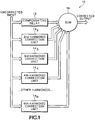
- the outputs from the individual harmonic correction units 14 2-M and the compensating delay circuit 12 are then input to a summer 16 to produce a harmonic corrected signal.
- a harmonic correction unit 14 has an input amplitude and phase correction filter 18 followed by a Hilbert Transformer filter 20 and in parallel another compensating delay circuit 22 to produce S and C (sin and cos) signals that are input in parallel to subsequent phase shift units 24 0-(n-1) .
- the outputs of the phase shift units 24 0-(n-1) are provided as harmonic corrected outputs to a multiplier 26 , the output of which is the output from the harmonic correction unit 14 that is input to the summer 16 .
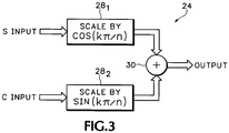
- each phase shift unit 24 receives the S and C inputs in respective scalers 28 1-2 .
- the scale factor is cos(k ⁇ /n)
- the scale factor is sin(k ⁇ /n).
- the scaled S and C outputs are input to phase summer 30 to provide the phase shift output from the phase shift unit 24 to the multiplier 26 .
- the calibration procedure is simpler than for the power-based solution, as each harmonic is calibrated independently of the others. First the amplitude/phase compensation filters 18 are bypassed so that they do not interfere with subsequent amplitude/phase measurements. Then the calibration follows the steps below:
- the present invention provides linearity compensation using harmonic cancellation by generating a separate harmonic correction component for each harmonic within a frequency range of interest using Hilbert Transformer filters and phase shifting, and summing the separate harmonic correction components to provide a corrected output.
Landscapes
- Engineering & Computer Science (AREA)
- Theoretical Computer Science (AREA)
- Amplifiers (AREA)
- Filters And Equalizers (AREA)
Applications Claiming Priority (2)
| Application Number | Priority Date | Filing Date | Title |
|---|---|---|---|
| US10/817,203 US6911925B1 (en) | 2004-04-02 | 2004-04-02 | Linearity compensation by harmonic cancellation |
| US817203 | 2006-06-27 |
Publications (3)
| Publication Number | Publication Date |
|---|---|
| EP1583243A2 EP1583243A2 (en) | 2005-10-05 |
| EP1583243A3 EP1583243A3 (en) | 2006-06-28 |
| EP1583243B1 true EP1583243B1 (en) | 2017-06-07 |
Family
ID=34679453
Family Applications (1)
| Application Number | Title | Priority Date | Filing Date |
|---|---|---|---|
| EP05252069.9A Expired - Lifetime EP1583243B1 (en) | 2004-04-02 | 2005-04-01 | Linearity compensation by harmonic cancellation |
Country Status (4)
| Country | Link |
|---|---|
| US (1) | US6911925B1 (ja) |
| EP (1) | EP1583243B1 (ja) |
| JP (1) | JP4498184B2 (ja) |
| CN (1) | CN1677870B (ja) |
Families Citing this family (22)
| Publication number | Priority date | Publication date | Assignee | Title |
|---|---|---|---|---|
| ES2541927T3 (es) | 2002-07-12 | 2015-07-28 | Ricoh Company, Ltd. | Dispositivo de calentamiento, dispositivo de suministro de potencia auxiliar, sistema de suministro de potencia auxiliar, dispositivo de fijación, y aparato de formación de imagen |
| US7348908B2 (en) * | 2004-11-04 | 2008-03-25 | Tektronix, Inc. | Linearity corrector using filter products |
| US7161511B2 (en) * | 2005-06-03 | 2007-01-09 | General Electric Company | Linearization system and method |
| US7460043B2 (en) * | 2005-06-03 | 2008-12-02 | General Electric Company | Analog-to-digital converter compensation system and method |
| GB2442265A (en) * | 2006-09-30 | 2008-04-02 | Univ Cardiff | Nonlinear signal processing |
| US20090091487A1 (en) * | 2007-10-04 | 2009-04-09 | Texas Instruments Incorporated | Spurious Free Dynamic Range Of An Analog To Digital Converter |
| JP2010117338A (ja) * | 2008-10-16 | 2010-05-27 | Advantest Corp | 信号処理装置、試験システム、歪検出装置、信号補償装置、解析信号生成装置、プログラム、記憶媒体、歪検出方法、信号補償方法、および、解析信号生成方法 |
| US8625813B2 (en) * | 2008-12-23 | 2014-01-07 | Stmicroelectronics, Inc. | Asymmetric polynomial psychoacoustic bass enhancement |
| JP5609684B2 (ja) * | 2011-02-01 | 2014-10-22 | ソニー株式会社 | Ad変換装置および信号処理システム |
| CN103023498A (zh) * | 2012-12-31 | 2013-04-03 | 深圳市九洲电器有限公司 | 一种提高数模转换器非线性失真性能的方法及装置 |
| US9112457B1 (en) | 2013-01-29 | 2015-08-18 | Teledyne Lecroy, Inc. | Decompressor |
| US10241031B2 (en) | 2014-07-08 | 2019-03-26 | Osaka University | Measuring device and measuring method |
| CN107040214B (zh) * | 2017-03-03 | 2021-01-29 | 北京东方计量测试研究所 | 一种基于多点补偿方案的低杂散正弦信号发生器 |
| US11489847B1 (en) * | 2018-02-14 | 2022-11-01 | Nokomis, Inc. | System and method for physically detecting, identifying, and diagnosing medical electronic devices connectable to a network |
| US10574250B1 (en) * | 2019-02-28 | 2020-02-25 | Nxp Usa, Inc. | Digital calibration systems and methods for multi-stage analog-to-digital converters |
| CN111277267A (zh) * | 2020-03-05 | 2020-06-12 | 中国人民解放军国防科技大学 | 双通道tiadc的时延失配补偿方法、装置及电子设备 |
| CN111682912B (zh) * | 2020-05-29 | 2022-03-08 | 中国科学院微电子研究所 | 一种基于fpga的超宽带功放谐波消除装置及方法 |
| CN112084732B (zh) * | 2020-08-12 | 2024-03-01 | 中电科思仪科技股份有限公司 | 一种基于fpga的谐波补偿方法 |
| WO2022150744A1 (en) | 2021-01-11 | 2022-07-14 | Ysi, Inc. | Induced crosstalk circuit for improved sensor linearity |
| CN112763769B (zh) * | 2021-04-08 | 2021-07-06 | 深圳市鼎阳科技股份有限公司 | 一种具有超低谐波失真的信号发生器 |
| CN114123205B (zh) * | 2021-11-01 | 2023-12-22 | 深圳供电局有限公司 | 谐波补偿系统及其相位校正方法与装置 |
| CN114283857B (zh) * | 2021-12-16 | 2024-05-28 | 上海艾为电子技术股份有限公司 | 分频信号的延时补偿、分频方法、系统和分频器 |
Family Cites Families (17)
| Publication number | Priority date | Publication date | Assignee | Title |
|---|---|---|---|---|
| US4615038A (en) * | 1984-06-06 | 1986-09-30 | At&T Information Systems Inc. | Equalization of modulated data signals utilizing tentative and final decisions and replication of non-linear channel distortion |
| JPS61129908A (ja) * | 1984-11-28 | 1986-06-17 | Toshiba Corp | 3逓倍回路 |
| JPH07118649B2 (ja) | 1986-01-08 | 1995-12-18 | ヤマハ株式会社 | デイザ回路 |
| JPS63121916U (ja) * | 1987-01-30 | 1988-08-08 | ||
| US5168526A (en) * | 1990-10-29 | 1992-12-01 | Akg Acoustics, Inc. | Distortion-cancellation circuit for audio peak limiting |
| GB9026906D0 (en) * | 1990-12-11 | 1991-01-30 | B & W Loudspeakers | Compensating filters |
| US5196851A (en) * | 1991-05-24 | 1993-03-23 | Samsung Electronics Co., Ltd. | Linearizing non-linear analog-to-digital process and circuit |
| JPH07321613A (ja) * | 1994-05-24 | 1995-12-08 | Kokusai Electric Co Ltd | 周波数逓倍器、波形整形回路、可変位相シフト回路 |
| US5617058A (en) * | 1995-11-13 | 1997-04-01 | Apogee Technology, Inc. | Digital signal processing for linearization of small input signals to a tri-state power switch |
| JPH10303708A (ja) * | 1997-04-24 | 1998-11-13 | Nec Corp | 周波数逓倍回路 |
| JPH1117749A (ja) * | 1997-06-24 | 1999-01-22 | Nec Corp | 復調回路 |
| US6177893B1 (en) * | 1998-09-15 | 2001-01-23 | Scott R. Velazquez | Parallel processing analog and digital converter |
| US6198416B1 (en) | 1999-04-16 | 2001-03-06 | Scott R. Velazquez | Linearity error compensator |
| US6584205B1 (en) * | 1999-08-26 | 2003-06-24 | American Technology Corporation | Modulator processing for a parametric speaker system |
| US6424275B1 (en) | 2001-01-18 | 2002-07-23 | Scott R. Velazquez | Linearity error compensator |
| JP3772970B2 (ja) * | 2001-10-29 | 2006-05-10 | ソニー株式会社 | D/a変換器および出力増幅回路 |
| US6570514B1 (en) | 2001-12-21 | 2003-05-27 | Scott R. Velazquez | Linearity error compensator |
-
2004
- 2004-04-02 US US10/817,203 patent/US6911925B1/en not_active Expired - Lifetime
-
2005
- 2005-03-23 JP JP2005083845A patent/JP4498184B2/ja not_active Expired - Lifetime
- 2005-04-01 EP EP05252069.9A patent/EP1583243B1/en not_active Expired - Lifetime
- 2005-04-01 CN CN2005100651465A patent/CN1677870B/zh not_active Expired - Lifetime
Also Published As
| Publication number | Publication date |
|---|---|
| EP1583243A3 (en) | 2006-06-28 |
| CN1677870B (zh) | 2010-06-09 |
| US6911925B1 (en) | 2005-06-28 |
| CN1677870A (zh) | 2005-10-05 |
| EP1583243A2 (en) | 2005-10-05 |
| JP2005295542A (ja) | 2005-10-20 |
| JP4498184B2 (ja) | 2010-07-07 |
Similar Documents
| Publication | Publication Date | Title |
|---|---|---|
| EP1583243B1 (en) | Linearity compensation by harmonic cancellation | |
| US8917125B1 (en) | Interleaving analog-to-digital converter (ADC) with background calibration | |
| Mishali et al. | Xampling: Analog to digital at sub-Nyquist rates | |
| CN109936366B (zh) | 信号路径线性化 | |
| EP1655838B1 (en) | Linearity corrector using filter products | |
| US8410843B2 (en) | Polyphase nonlinear digital predistortion | |
| US9030340B1 (en) | N-path interleaving analog-to-digital converter (ADC) with background calibration | |
| US9945901B1 (en) | Measuring and correcting non-idealities of a system | |
| US20090033538A1 (en) | Ramp Linearization for FMCW Radar Using Digital Down-Conversion of a Sampled VCO Signal | |
| KR20100080391A (ko) | 2채널의 타임 인터리빙 아날로그 디지털 변환기 및 그의 오차 측정 및 정정 방법 | |
| US6600438B2 (en) | Broadband IF conversion using two ADCs | |
| JPWO2006075505A1 (ja) | 改良された時間インタリーブ方式のアナログ−デジタル変換装置及びそれを用いる高速信号処理システム | |
| US8842033B1 (en) | Dynamic linearity corrector for digital-to-analog converters | |
| JP4076553B2 (ja) | 校正装置及び線形補正器校正方法 | |
| US6950048B1 (en) | Dither system for a quantizing device | |
| JP2004328436A (ja) | A/d変換装置 | |
| US20150180495A1 (en) | Converter arrangement and method for converting an analogue input signal into a digital output signal | |
| US7038602B1 (en) | Method for correcting periodic sampling errors | |
| JP4451486B2 (ja) | アナログ/デジタル変換装置およびデジタル/アナログ変換装置 | |
| CN1790916B (zh) | 使用滤波器乘积的线性校正器的校准系统 | |
| JP7734235B2 (ja) | 位相ノイズ影響除去用の補正システムとそれを含むアナログ・デジタル変換装置 | |
| JP6512092B2 (ja) | 周波数特性補正回路 | |
| CN114024627A (zh) | 针对宽带调制信号实现快速全频段频响补偿处理的方法、装置、处理器及其存储介质 | |
| Mankovskyy et al. | Digital Method of SSB Modulation | |
| EP1933459A1 (en) | Linearity corrector using filter products |
Legal Events
| Date | Code | Title | Description |
|---|---|---|---|
| PUAI | Public reference made under article 153(3) epc to a published international application that has entered the european phase |
Free format text: ORIGINAL CODE: 0009012 |
|
| AK | Designated contracting states |
Kind code of ref document: A2 Designated state(s): AT BE BG CH CY CZ DE DK EE ES FI FR GB GR HU IE IS IT LI LT LU MC NL PL PT RO SE SI SK TR |
|
| AX | Request for extension of the european patent |
Extension state: AL BA HR LV MK YU |
|
| PUAL | Search report despatched |
Free format text: ORIGINAL CODE: 0009013 |
|
| AK | Designated contracting states |
Kind code of ref document: A3 Designated state(s): AT BE BG CH CY CZ DE DK EE ES FI FR GB GR HU IE IS IT LI LT LU MC NL PL PT RO SE SI SK TR |
|
| AX | Request for extension of the european patent |
Extension state: AL BA HR LV MK YU |
|
| 17P | Request for examination filed |
Effective date: 20060731 |
|
| 17Q | First examination report despatched |
Effective date: 20061208 |
|
| AKX | Designation fees paid |
Designated state(s): DE FR GB IT |
|
| RAP1 | Party data changed (applicant data changed or rights of an application transferred) |
Owner name: TEKTRONIX, INC. |
|
| GRAP | Despatch of communication of intention to grant a patent |
Free format text: ORIGINAL CODE: EPIDOSNIGR1 |
|
| STAA | Information on the status of an ep patent application or granted ep patent |
Free format text: STATUS: GRANT OF PATENT IS INTENDED |
|
| INTG | Intention to grant announced |
Effective date: 20161123 |
|
| GRAS | Grant fee paid |
Free format text: ORIGINAL CODE: EPIDOSNIGR3 |
|
| GRAA | (expected) grant |
Free format text: ORIGINAL CODE: 0009210 |
|
| STAA | Information on the status of an ep patent application or granted ep patent |
Free format text: STATUS: THE PATENT HAS BEEN GRANTED |
|
| AK | Designated contracting states |
Kind code of ref document: B1 Designated state(s): DE FR GB IT |
|
| REG | Reference to a national code |
Ref country code: GB Ref legal event code: FG4D |
|
| GRAA | (expected) grant |
Free format text: ORIGINAL CODE: 0009210 |
|
| REG | Reference to a national code |
Ref country code: DE Ref legal event code: R096 Ref document number: 602005052071 Country of ref document: DE |
|
| PG25 | Lapsed in a contracting state [announced via postgrant information from national office to epo] |
Ref country code: IT Free format text: LAPSE BECAUSE OF FAILURE TO SUBMIT A TRANSLATION OF THE DESCRIPTION OR TO PAY THE FEE WITHIN THE PRESCRIBED TIME-LIMIT Effective date: 20170607 |
|
| REG | Reference to a national code |
Ref country code: DE Ref legal event code: R097 Ref document number: 602005052071 Country of ref document: DE |
|
| PLBE | No opposition filed within time limit |
Free format text: ORIGINAL CODE: 0009261 |
|
| STAA | Information on the status of an ep patent application or granted ep patent |
Free format text: STATUS: NO OPPOSITION FILED WITHIN TIME LIMIT |
|
| 26N | No opposition filed |
Effective date: 20180308 |
|
| PGFP | Annual fee paid to national office [announced via postgrant information from national office to epo] |
Ref country code: GB Payment date: 20180427 Year of fee payment: 14 |
|
| PG25 | Lapsed in a contracting state [announced via postgrant information from national office to epo] |
Ref country code: FR Free format text: LAPSE BECAUSE OF NON-PAYMENT OF DUE FEES Effective date: 20180430 |
|
| GBPC | Gb: european patent ceased through non-payment of renewal fee |
Effective date: 20190401 |
|
| PG25 | Lapsed in a contracting state [announced via postgrant information from national office to epo] |
Ref country code: GB Free format text: LAPSE BECAUSE OF NON-PAYMENT OF DUE FEES Effective date: 20190401 |
|
| P01 | Opt-out of the competence of the unified patent court (upc) registered |
Effective date: 20230530 |
|
| PGFP | Annual fee paid to national office [announced via postgrant information from national office to epo] |
Ref country code: DE Payment date: 20240429 Year of fee payment: 20 |
|
| REG | Reference to a national code |
Ref country code: DE Ref legal event code: R071 Ref document number: 602005052071 Country of ref document: DE |