EP1582938A2 - Tonerbehälter, Entwicklungsgerät, Bilderzeugungsgerät - Google Patents
Tonerbehälter, Entwicklungsgerät, Bilderzeugungsgerät Download PDFInfo
- Publication number
- EP1582938A2 EP1582938A2 EP05102531A EP05102531A EP1582938A2 EP 1582938 A2 EP1582938 A2 EP 1582938A2 EP 05102531 A EP05102531 A EP 05102531A EP 05102531 A EP05102531 A EP 05102531A EP 1582938 A2 EP1582938 A2 EP 1582938A2
- Authority
- EP
- European Patent Office
- Prior art keywords
- toner
- chamber
- screw conveyor
- partition wall
- agitating member
- Prior art date
- Legal status (The legal status is an assumption and is not a legal conclusion. Google has not performed a legal analysis and makes no representation as to the accuracy of the status listed.)
- Granted
Links
Images



Classifications
-
- G—PHYSICS
- G03—PHOTOGRAPHY; CINEMATOGRAPHY; ANALOGOUS TECHNIQUES USING WAVES OTHER THAN OPTICAL WAVES; ELECTROGRAPHY; HOLOGRAPHY
- G03G—ELECTROGRAPHY; ELECTROPHOTOGRAPHY; MAGNETOGRAPHY
- G03G21/00—Arrangements not provided for by groups G03G13/00 - G03G19/00, e.g. cleaning, elimination of residual charge
- G03G21/10—Collecting or recycling waste developer
- G03G21/12—Toner waste containers
-
- G—PHYSICS
- G03—PHOTOGRAPHY; CINEMATOGRAPHY; ANALOGOUS TECHNIQUES USING WAVES OTHER THAN OPTICAL WAVES; ELECTROGRAPHY; HOLOGRAPHY
- G03G—ELECTROGRAPHY; ELECTROPHOTOGRAPHY; MAGNETOGRAPHY
- G03G15/00—Apparatus for electrographic processes using a charge pattern
- G03G15/06—Apparatus for electrographic processes using a charge pattern for developing
- G03G15/08—Apparatus for electrographic processes using a charge pattern for developing using a solid developer, e.g. powder developer
- G03G15/0822—Arrangements for preparing, mixing, supplying or dispensing developer
- G03G15/0848—Arrangements for testing or measuring developer properties or quality, e.g. charge, size, flowability
- G03G15/0849—Detection or control means for the developer concentration
- G03G15/0855—Detection or control means for the developer concentration the concentration being measured by optical means
-
- G—PHYSICS
- G03—PHOTOGRAPHY; CINEMATOGRAPHY; ANALOGOUS TECHNIQUES USING WAVES OTHER THAN OPTICAL WAVES; ELECTROGRAPHY; HOLOGRAPHY
- G03G—ELECTROGRAPHY; ELECTROPHOTOGRAPHY; MAGNETOGRAPHY
- G03G15/00—Apparatus for electrographic processes using a charge pattern
- G03G15/06—Apparatus for electrographic processes using a charge pattern for developing
- G03G15/08—Apparatus for electrographic processes using a charge pattern for developing using a solid developer, e.g. powder developer
- G03G15/0822—Arrangements for preparing, mixing, supplying or dispensing developer
- G03G15/0865—Arrangements for supplying new developer
-
- G—PHYSICS
- G03—PHOTOGRAPHY; CINEMATOGRAPHY; ANALOGOUS TECHNIQUES USING WAVES OTHER THAN OPTICAL WAVES; ELECTROGRAPHY; HOLOGRAPHY
- G03G—ELECTROGRAPHY; ELECTROPHOTOGRAPHY; MAGNETOGRAPHY
- G03G15/00—Apparatus for electrographic processes using a charge pattern
- G03G15/06—Apparatus for electrographic processes using a charge pattern for developing
- G03G15/08—Apparatus for electrographic processes using a charge pattern for developing using a solid developer, e.g. powder developer
- G03G15/0822—Arrangements for preparing, mixing, supplying or dispensing developer
- G03G15/0865—Arrangements for supplying new developer
- G03G15/0875—Arrangements for supplying new developer cartridges having a box like shape
-
- G—PHYSICS
- G03—PHOTOGRAPHY; CINEMATOGRAPHY; ANALOGOUS TECHNIQUES USING WAVES OTHER THAN OPTICAL WAVES; ELECTROGRAPHY; HOLOGRAPHY
- G03G—ELECTROGRAPHY; ELECTROPHOTOGRAPHY; MAGNETOGRAPHY
- G03G21/00—Arrangements not provided for by groups G03G13/00 - G03G19/00, e.g. cleaning, elimination of residual charge
- G03G21/10—Collecting or recycling waste developer
- G03G21/105—Arrangements for conveying toner waste
Definitions
- the present invention generally relates to a toner cartridge, a developing unit, and an image forming apparatus.
- Fig. 15 is a side cross-sectional view of a waste toner chamber 105 of a conventional toner cartridge 102 for use in an electrophotographic printer.
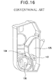
- Fig. 16 is a perspective view of a lid mounted to close one end of the toner cartridge 102 that extends in a longitudinal direction.
- the toner cartridge 102 includes a fresh toner chamber 104 that holds fresh toner therein and a waste toner chamber 105 that holds waste toner therein.
- the fresh toner chamber 104 and waste toner chamber 105 extend in their longitudinal directions and are divided by a longitudinally extending partition wall.
- the fresh toner chamber 104 includes an agitating bar 106 for agitating the fresh toner in the fresh toner chamber 104.
- the agitating bar 106 is connected to a drive gear 107, which is driven to rotate by an external drive source.
- the waste toner chamber 105 incorporates a screw conveyor 143 that moves the waste toner, collected form the developing unit, into the waste toner chamber 105.
- the agitating bar 106 in the fresh toner chamber 104 and the screw conveyor 143 need to be driven by separate drive sources. Driving the toner agitating bar 106 and screw conveyor 143 by separate drive sources makes the construction complicated and results in an increased number of parts.
- the present invention was made to solve the problems of the aforementioned conventional art.
- An object of the invention is to provide a toner cartridge of simple construction that requires a small number of parts.
- a toner cartridge holds toner therein.
- a toner holding chamber (5+4) holds toner therein.
- the toner holding chamber includes a first chamber (5 or 4) and a second chamber (4 or 5) .
- a partition wall (3) divides the toner holding chamber (5+4) into the first chamber (5 or 4) and the second chamber (4 or 5).
- a toner moving member (43, 8) causes the toner in the first chamber (5 or 4) to move.
- An agitating member (6, 6a) agitates the toner in the second chamber (4 or 5) .
- the toner moving member (43) and the agitating member (6) are operatively coupled so that when one of the toner moving member (43) and the agitating member (6) is driven in rotation, the other of the toner moving member (43) and the agitating member (6) also rotates.
- the first chamber (5 or 4) and the second chamber (4 or 5) are aligned in a longitudinal direction of the toner cartridge.
- the second chamber (4) has a larger toner-holding capacity than the first chamber (5).
- the toner moving member (43) is a first screw conveyor (43, 43a).
- the first screw conveyor (43, 43a) causes the toner in the first chamber (5) to move.
- the first screw conveyor (43, 43a) spans across substantially half a length of the first chamber (5).
- the first chamber (5 or 4) has a first opening (42) through which waste toner is received from an external section into the first chamber (5 or 4).
- the second chamber (4 or 5) has a second opening (40) through which fresh toner is discharged from the second chamber (4), the second opening (40) being located under the agitating member (6, 6a).
- the agitating member (6) is a toner agitating bar (6a) that agitates the toner in the second chamber (4) when the agitating member (6, 6a) is driven to rotate.
- the agitating member (6, 6a) has a second screw conveyor (12) that causes the toner to move in the second chamber (4) when the agitating member (6, 6a) is driven to rotate.
- the toner moving member (43) and the agitating member (6, 6a) are coupled through a coupling mechanism that extends through an opening formed in the partition wall (3).
- the partition wall (3) has a leakage preventing structure that prevents the toner from leaking between the first chamber (5 or 4) and the second chamber (4 or 5).
- the leakage preventing structure includes a third screw conveyor (8) formed on the toner moving member (43) in the vicinity of the partition wall (3).
- the partition wall (3) includes a hollow cylinder (9) that projects from the partition wall (3) into the first chamber (5) in such a way that at least a part of the third screw conveyor (8) is rotatably received.
- the first opening (42) is formed in a first wall (45) that opposes the partition wall (3).
- the toner moving member (43, 43a) has a screw conveyor (43, 43a) under the first opening (42).
- the agitating member (6) has an agitator bar (6a). When the agitating member (6) is rotated, the agitator bar (6a) agitates the toner in the second chamber (4) and the second screw conveyor (12) causes the toner in the first chamber (4) to move.
- the second chamber (4) has a second wall that opposes the partition wall (3).
- the second screw conveyor (12) is on a side close to the second wall and the agitator bar (6a) is on a side close to the partition wall (3).
- a developing apparatus includes a toner cartridge attached to it.
- the developing apparatus (1) includes a toner reservoir, a developing roller, and a toner supplying roller.
- the toner reservoir (41) holds toner therein.
- the developing roller (22) supplies the toner to a photoconductive drum (24).
- the toner supplying roller (21) supplies the toner to the developing roller (22).
- the toner cartridge (2) includes a toner holding chamber, a partition wall, a toner moving member, and an agitating member.
- the toner holding chamber (5, 4) holds toner therein and includes a first chamber (5) and a second chamber (4) .
- the first chamber (5) has a first opening (42) through which waste toner is received from an external section into the first chamber (5), and the second chamber (4) has a second opening (40) through which the toner is discharged from the second chamber (4) .
- the second opening (40) is located under the agitating member (6, 6a).
- the partition wall (3) divides the toner holding chamber (5+4) into the first chamber (5) and the second chamber (4).
- the toner moving member (43, 43a, 8) causes the toner in the first chamber (5) .
- the agitating member (6, 6a) agitates the toner in the second chamber (4).
- the toner moving member (43, 43a, 8) and the agitating member (6, 6a) are operatively coupled in such a way that when one of the toner moving member (43, 43a, 8) and the agitating member (6, 6a) is driven in rotation, the other of the toner moving member (43, 43a, 8) and the agitating member (6, 6a) also rotate.
- the toner moving member causes the toner in the first chamber to move and the toner in the second chamber (4) is agitated by the agitating member (6, 6a) and discharged into the developing apparatus through the second opening (40).
- the toner cartridge is detachably attached to the developing apparatus (1).
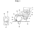
- Fig. 1 is a schematic view of an image forming section of an image forming apparatus such as a printer.
- a toner cartridge 2 according to a first embodiment is attached to a developing unit 1 and toner is supplied through a toner exit 40.
- a charging roller 27 is driven by a drive source, not shown, to rotate in contact with a surface of a photoconductive drum 24, thereby charging the surface of the photoconductive drum 24 to a predetermined potential.
- An exposing unit 25 provided on the body of the printer illuminates the uniformly charged surface of the photoconductive drum 24 to form an electrostatic latent image in accordance with print data.
- a toner cartridge 2 is detachably attached to a developing unit 1. Fresh, unused toner is supplied from the toner cartridge 2 into the developing unit 1.
- the developing unit 1 is detachably attached to the image forming apparatus.
- a toner-supplying roller 21 supplies the toner to a developing roller 22 while rotating.
- a developing blade 23 is in contact with the developing roller 22. When the developing roller 22 rotates, the developing blade 23 forms a thin layer of toner on the surface of the developing roller 22.
- the toner layer is brought into contact with the electrostatic latent image so that the electrostatic latent image is developed into a toner image.
- a recording medium 20 is fed from a paper cassette, not shown, and passes a transfer point defined between the photoconductive drum 24 and a transfer roller 26, the toner image is transferred onto the recording medium 20.
- the recording medium 20 having the toner image on it is then transported in a direction shown by arrow P to a fixing unit 29.
- the fixing unit 29 includes fixing rollers 30 and 31 that incorporate a heat source, not shown.
- the recording medium 20 passes a fixing point defined between the fixing rollers 30 and 31, the toner image on the recording medium 20 is subjected to heat and pressure so that the toner image is fused into a permanent image.
- the recording medium 20 is then discharged by a mechanism, not shown, to the outside of the image forming apparatus.
- waste toner on the photoconductive drum 24 fails to be transferred onto the recording medium 20, and remains as waste toner on the photoconductive drum 24.
- a cleaning blade 28 scrapes the residual toner from the photoconductive drum 24 and the scraped toner is received into a waste toner reservoir 32.
- the waste toner in the waste toner reservoir 32 is transferred by a transporting means, not shown, to a side wall 33 (Fig. 3).
- the waste toner arrives at the side wall 33 and is transported by a transporting mechanism, not shown, incorporated in the side wall 33, to a waste toner exit 34.
- the waste toner is collected through the waste toner exit 34 into a waste toner chamber 5 (Fig. 5) of the toner cartridge 2 attached to the developing unit 1.
- Fig. 2 is a perspective view of the toner cartridge 2 attached to the developing unit 1.
- Fig. 3 is a front view of the developing unit 1.
- Fig. 4 is a front view of the toner cartridge 2 attached to the developing unit 1.
- a toner level sensor monitors the toner level in a fresh toner chamber 4 (Fig. 5) .
- the image forming apparatus indicates when the toner level reaches a predetermined value.
- the user operates a lever 19 to close the toner exit 40 and cause the toner cartridge 2 to disengage from the developing unit 1. Then, the user detaches the toner cartridge 2. At this moment, the amount of waste toner held in the waste toner chamber 5 may be large or may be small, depending on the type of printing performed up to that time.
- the toner cartridge 2 is attached to the developing unit 1 in such a way that the toner cartridge 2 and the developing unit 1 communicate with each other through a waste toner inlet 42 (Fig. 5) and the waste toner exit 34 formed in the side wall 33 (Fig. 3) of the developing unit 1, thereby completely attaching the toner cartridge 2 to the developing unit 1. Then, when the operator rotates the lever 19, an engagement portion, not shown, of the toner cartridge 2 engages an engagement portion of the developing unit 1 and a drive gear 7 (Fig. 5) moves into meshing engagement with the driving mechanism on the developing unit 1 side.
- the toner exit 40 formed in the bottom of the toner cartridge 2 is operatively associated with the lever 19, so that when the user operates the lever 19, the fresh toner falls from the fresh toner chamber 4 into the developing unit 1 (Fig. 1).
- the toner exit 40 extends substantially across the full longitudinal length of the fresh toner chamber 4.
- Fig. 5 is a cross-sectional side view illustrating the details of the toner cartridge 2 according to the first embodiment.
- Fig. 6 is a fragmentary perspective view with a cross-section taken along line I-I of Fig. 5.
- Fig. 7 is a fragmentary perspective view with a cross-section taken along line II-II of Fig. 5.
- Figs. 6 and 7 illustrate pertinent portions of the toner cartridge 2 without details.
- the toner cartridge 2 is a hollow body extending in a longitudinal direction, and includes the fresh toner chamber 4 and the waste toner chamber 5 divided by a partition wall 3.
- the fresh toner chamber 4 has a larger toner-holding capacity than the waste toner chamber 5.
- a lid 45 closes one longitudinal end of the toner chamber 2.
- the lid 45 incorporates a drive mechanism that drives a later described screw conveyor 43 and an agitator bar 6. This drive mechanism is driven by an external drive source.
- Another lid 46 closes another longitudinal end of the toner cartridge 2, and has the lever 19 that is operated by the user to open and close the toner exit 40.
- the screw conveyor 43 includes a longitudinally extending shaft 43b and a blade 43a that spirals around the shaft 43b.
- the screw conveyor 43 is rotatably supported.
- the agitator bar 6 has a crank 6a and extends in a longitudinal direction.
- the agitator bar 6 is rotatable about the longitudinal direction.
- the shaft 43b of the screw conveyor 43 has a large diameter portion 100a and the shaft 6b of the agitator bar 6 has a large diameter portion 100b.
- the shaft 43b and shaft 6b are coupled to each other through the large-diameter portions 100a and 100b, which are rotatably fitted into the partition wall 3.
- the waste toner entered into the waste toner chamber 5 falls onto the screw conveyor 43.
- the screw conveyor 43 rotates in the E direction, the toner is carried on the screw conveyor 43, while being dispersed little by little.
- One end of the shaft 6b of the agitator bar 6 is coupled to the shaft 43b of the screw conveyor 43 in such a way that the two shafts 6b and 43b are in line with each other.
- Another end of the shaft 6b of the agitator bar 6 is rotatably supported by the lid 46 that opposes the partition wall 3.
- the screw conveyor 43 and agitator bar 6 are required to have a certain mechanical strength, and thus, are made of ABS resin. Highly rigid ABS resin containing a glass fiber is highly desirable.
- the spiral blade 43a of the screw conveyor 43 according to the embodiment has a diameter and a pitch, which are about 10 mm, but are not limited to these values. The diameter and pitch may be of any values provided that the rotation of the spiral can disperse and move the waste toner in the waste toner chamber 5. In order that the collected waste toner is moved to the middle portion of the waste toner chamber 5, the spiral extends over only half the full length of the waste toner chamber 5. The aforementioned requirements may be modified as required.
- Fig. 8 illustrates the large-diameter portions 100a and 100b before they are assembled in a direction shown by arrow F into a hole 101 formed in the partition wall 3.
- Fig. 9 illustrates the large diameter portions 100a and 100b after the large diameter portions 100a and 100b are pushed into the hole 101.
- an annular projection 101a that defines the hole 101 deforms, allowing the large-diameter portions 100a and 100b to enter the hole 101.
- the partition wall 3 has a hollow cylinder portion 104 that extends toward the interior of the waste toner chamber 5.
- a disk-like stopper 103 adjacent to the large diameter portion 100a.
- the disk-like stopper 103 is concentric to the shaft 43b of the screw conveyor 43.
- the cylinder portion 104 has a smaller outer diameter than the disk-like stopper 103, and therefore abuts the disk-like stopper 103.
- the wall of the cylinder 104 is normal to the disk-like stopper 103.
- the ring shaped annular projection 101a has a surface normal to the direction in which the large-diameter portion 100b enters the partition wall 3.
- the annular projection 101a serves as a stopper against the large diameter portion 100b, preventing the large-diameter portion 100b from moving into the waste toner chamber 5.
- Fig. 10 illustrates the details of the structure of the large diameter portion.
- the screw conveyor 43 and the agitator bar 6 in Figs. 8 and 9 are coupled together by means of a screw, i.e., mechanical coupling.
- the shaft 6b of the agitator bar 6 has a male screw S1 and the large-diameter portion 100a has a female screw S2.
- the screw conveyor 43 is rotated relative to the large-diameter portion 100a, thereby being fitted into the hole 101.
- the male screw is rotated into the female screw in such a direction that when the screw conveyor 43 is rotated, the male screw remains firmly screwed into the female screw.
- the agitator bar 6 of the fresh toner chamber 4 will now be described.
- the crank 6a should spans over the substantially full length of the fresh toner exit 40 while also being prevented from colliding with the inner wall of the fresh toner chamber 4.
- the crank 6a should extend substantially across the full length of the toner exit 40.
- the agitator bar 6 should be bent at angle ⁇ to form the crank 6a so that the agitator bar 6 can extend into the partition wall 3 through the hole formed in the partition wall 3. Taking the aforementioned requirements into account, the angle ⁇ is selected to be 60° in the embodiment.
- the agitator bar 6 may be any shapes provided that the toner in the fresh toner chamber 4 is properly agitated and discharged through the toner exit 40.
- the apparatus operates as follows:
- the waste toner collecting mechanism not shown, collects the waste toner resulting from failure of transfer of part of toner images, and transports the waste toner to the waste toner chamber 5.
- a drive source is provided on the developing unit side and is coupled to the drive gear 7.
- the drive source drives the drive gear 7 to rotate so that the drive gear 7 drives the screw conveyor 43 coupled to the drive gear 7 to rotate.
- the waste toner enters the waste toner chamber 5 through the waste toner inlet 42 and falls onto the screw conveyor 43.
- the screw conveyor 43 moves the waste toner toward the back end portion of the waste chamber 5 while dispersing the waste toner. In this manner, the waste toner is collected into the waste toner chamber 5.
- the agitator 6 also rotates.
- the fresh toner in the fresh toner chamber 4 continues to be supplied into the toner reservoir 41, while being agitated by the agitator bar 6.
- the screw conveyor 43 causes the waste toner to move in the waste toner chamber 5
- the toner exerts a force on the screw conveyor 43 acting to push back in a direction opposite to arrow A in Fig. 5.
- the large-diameter portion 100b abuts an annular projection 101a on the partition wall 3 to prevent the screw conveyor 43 and the agitator bar 6 from moving in their longitudinal directions, ensuring stable rotation of the screw conveyor 43.
- the toner cartridge 2 is designed to perform two modes of operations simultaneously.
- the agitator in the fresh toner chamber 4 does not have to be driven by a drive source separate from the screw conveyor in the waste toner chamber 5, so that the fresh toner holding space can be large to accommodate a large amount of fresh toner.
- Fig. 11 illustrates a toner cartridge 2 according to a second embodiment.
- the second embodiment differs from the first embodiment in that a screw conveyor 43 has a reverse screw conveyor 8.
- the waste toner is received in the waste toner chamber 5 through a waste toner inlet 42, and the screw conveyor 43 moves the waste toner toward the middle of the waste toner chamber 5 while dispersing the waste toner.
- an increase in the amount of waste toner gives rise to a possibility that the waste toner moving in the A direction leaks into the fresh toner chamber 4 through a hole 101 formed in a partition wall 3.
- the toner cartridge according to the second embodiment has the reverse screw conveyor 8 that has a blade 8a that spirals in the opposite direction to the screw conveyor 43.
- the reverse screw conveyor 8 causes the waste toner to move in a direction shown by arrow B opposite to the A direction, thereby preventing the waste toner from entering the hole 101.
- the reverse screw conveyor 8 is not enough to completely prevent the waste toner from entering the hole 101.
- the reverse screw conveyor 8 cooperates with a hollow cylinder 9 that projects from the partition wall 3.
- the hollow cylinder 9 has an inner diameter somewhat larger than that of the reverse screw conveyor 8.
- the hollow cylinder 9 loosely fits over the reverse screw conveyor 8, allowing the reverse screw conveyor 8 to rotate in the cylinder 9.
- the cylinder 9 is somewhat shorter than the reverse screw conveyor 8, so that the reverse screw conveyor 8 effectively causes the waste toner to move out of the hollow cylinder 9.
- the hollow cylinder 9 is preferably made in one piece with the partition wall 3.
- the fresh toner in the fresh toner chamber 4 is agitated by the agitator bar 6 and is discharged through the toner exit 40 into a developing unit 1.
- a toner-collecting mechanism collects residual toner into the waste toner chamber 5 of the toner cartridge 2.
- the screw conveyor 43 and the agitator bar 6 are coupled together by means of a mechanism, for example, that shown in Fig. 10.
- the second embodiment has both the reverse spiral 8 and the screw conveyor 43, and the reverse screw conveyor 8 is loosely fitted into the hollow cylinder 9, thereby further ensuring that the waste toner does not enter into the fresh toner chamber 4.
- An advantage of the second embodiment is that the configuration does not require any special sealing member.
- the provision of the reverse screw conveyor 8 prevents an excessive amount of waste toner from entering the hole 101 formed in the partition wall 3, thereby decreasing the mechanical load on the rotating agitator bar 6. Because the load on the agitator bar 6 is reduced, the agitator bar 6 may be made of a non-metal, light, and inexpensive material such as ABS resin.
- the screw conveyor 43 rotates to move the waste toner in the waste toner chamber 5
- the waste toner exerts a force on the screw conveyor 43 in the opposite direction to the A direction.
- the large-diameter portion 100b abuts the annular projection 101a of the partition wall 3 serving as a stopper, so that the screw conveyor 43 and agitator bar 6 are prevented from moving in their longitudinal directions. Therefore, this ensures stable, reliable rotation of the screw conveyor 43.
- Fig. 12 illustrates a toner cartridge according to a third embodiment.
- the third embodiment further improves the shapes of an agitator bar 6 and a partition wall 3 according to the second embodiment.
- an agitator bar 6 has a shaft 6b rotatably supported by a partition wall 3.
- the agitator 6 has a blade attached to a part of the shaft 6b, the blade describing a spiral about the shaft 6b to form a screw conveyor 10.
- the partition wall 3 has a hollow cylinder 11 that extends toward the middle portion of the fresh toner chamber 4.
- the shaft 43b of the screw conveyor 43 and the shaft 6b of the agitator bar 6 are in line with each other and are coupled through the same mechanism as that in Figs. 8-10.
- the hollow cylinder 11 has an inner diameter larger than an outer diameter of the screw conveyor 10, so that the hollow cylinder 11 receives the screw conveyor 10 therein and the screw conveyor10 is rotatable relative to the hollow cylinder 11.
- the hollow cylinder 11 is shorter than the screw conveyor 10 to ensure that the screw conveyor 10 pushes the fresh toner completely out of the hollow cylinder 11 in a direction shown by arrow C. This prevents the fresh toner from leaking into the waste toner chamber 5.
- a toner collecting mechanism collects the waste toner resulting from the transfer of toner images into the waste toner chamber 5 through a waste toner inlet 42.
- the rotation of the drive gear 7 causes the screw conveyor 43 to rotate, so that the spiral blade 43a of the screw conveyor 43 pushes the waste toner toward the partition wall 3 while dispersing the waste toner.
- the shaft 43b of the screw conveyor 43 has another spiral blade 8a that describes a spiral in the opposite direction to the screw conveyor 43.
- the spiral blade 8a on the shaft 43b forms a reverse screw conveyor 8.
- the reverse screw conveyor 8 and the screw conveyor 43 cause the waste toner to move in the opposite directions, thereby preventing the waste toner from entering the fresh toner chamber 4 through gaps between the coupling mechanism in Fig. 8-10 and the partition wall 3.
- the screw conveyor 10 mounted to the agitator bar 6 cooperates with the hollow cylinder 11 to prevent the fresh toner from entering the waste toner chamber 5.
- a fourth embodiment is directed to an improvement of the shape of the agitator bar 6 according to the third embodiment.
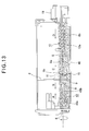
- Fig. 13 is a cross-sectional side view of a toner cartridge 2 according to the fourth embodiment.
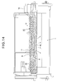
- Fig. 14 illustrates the toner cartridge 2 attached to a developing unit 1.
- the agitator bar 6 has a shorter crank 6c than the third embodiment.
- the agitator bar 6 has a screw conveyor 10 and a reverse screw conveyor 12 having a blade 12a that describes a spiral around a shaft 6b in a direction opposite to the screw conveyor 10.
- a shaft 43b of the screw conveyor 43 and a shaft 6b of the agitator bar 6 are in line with each other and are coupled through the same mechanism as that in Figs. 8-10.
- the screw conveyor 43 rotates to move waste toner toward a partition wall 3 while dispersing the waste toner.
- the agitator bar 6 also rotates to agitate fresh toner in a fresh toner chamber 4. Because the reverse screw conveyor 12 rotates to move the fresh toner toward a toner exit 40, the fresh toner is supplied more evenly across the longitudinal length of the developing unit 1 . The fresh toner is discharged from the fresh toner chamber 4 into the developing unit 1 through the toner exit 40.
- the toner exit 40 extends across substantially 2/3 of the longitudinal length of the fresh toner chamber 4 and therefore there is a tendency of the supply of fresh toner to be uneven across the length of the developing unit 1.
- the reverse screw conveyor 12 spans substantially half the length of the fresh toner chamber 4 and moves the fresh toner toward the partition wall 3 in a direction shown by arrow D, the fresh toner being supplied into the developing unit 1 through the toner exit 40 formed substantially in the longitudinally middle portion of the fresh toner chamber 4.
- the waste toner exerts a force on the blade 43a of the screw conveyor 43, acting in a direction shown by arrow A.
- the large-diameter portion 100b abuts the annular projection 101a that serves as a stopper, so that the screw conveyor 43 and the agitator bar 6 are prevented from moving in their longitudinal directions. This ensures stable, reliable rotation of the screw conveyor 43.
- the fresh toner is prevented from being distributed unevenly across the longitudinal direction of the developing unit 1, and the fresh toner is consumed efficiently in the developing unit 1.
Landscapes
- Physics & Mathematics (AREA)
- General Physics & Mathematics (AREA)
- Life Sciences & Earth Sciences (AREA)
- Engineering & Computer Science (AREA)
- Environmental & Geological Engineering (AREA)
- Sustainable Development (AREA)
- Dry Development In Electrophotography (AREA)
- Cleaning In Electrography (AREA)
- Screw Conveyors (AREA)
Applications Claiming Priority (2)
| Application Number | Priority Date | Filing Date | Title |
|---|---|---|---|
| JP2004105616A JP4545474B2 (ja) | 2004-03-31 | 2004-03-31 | トナー収容器、現像装置及び画像形成装置 |
| JP2004105616 | 2004-03-31 |
Publications (3)
| Publication Number | Publication Date |
|---|---|
| EP1582938A2 true EP1582938A2 (de) | 2005-10-05 |
| EP1582938A3 EP1582938A3 (de) | 2013-11-20 |
| EP1582938B1 EP1582938B1 (de) | 2016-08-17 |
Family
ID=34880073
Family Applications (1)
| Application Number | Title | Priority Date | Filing Date |
|---|---|---|---|
| EP05102531.0A Ceased EP1582938B1 (de) | 2004-03-31 | 2005-03-31 | Tonerbehälter, Entwicklungsgerät, Bilderzeugungsgerät |
Country Status (4)
| Country | Link |
|---|---|
| US (1) | US7272346B2 (de) |
| EP (1) | EP1582938B1 (de) |
| JP (1) | JP4545474B2 (de) |
| CN (1) | CN100555103C (de) |
Cited By (1)
| Publication number | Priority date | Publication date | Assignee | Title |
|---|---|---|---|---|
| EP3153929A4 (de) * | 2014-06-03 | 2018-01-17 | Kyocera Document Solutions Inc. | Tonerbehälter und bilderzeugungsvorrichtung |
Families Citing this family (22)
| Publication number | Priority date | Publication date | Assignee | Title |
|---|---|---|---|---|
| JP4083722B2 (ja) * | 2004-09-30 | 2008-04-30 | シャープ株式会社 | 現像剤収納容器 |
| JP4844222B2 (ja) * | 2006-04-28 | 2011-12-28 | 富士ゼロックス株式会社 | トナーカートリッジ |
| JP2008040222A (ja) * | 2006-08-08 | 2008-02-21 | Fuji Xerox Co Ltd | 現像剤カートリッジ及び画像形成装置 |
| JP2008090048A (ja) * | 2006-10-03 | 2008-04-17 | Fuji Xerox Co Ltd | トナーカートリッジ及び画像形成装置 |
| JP5003935B2 (ja) * | 2006-10-05 | 2012-08-22 | 富士ゼロックス株式会社 | 収容容器及び画像形成装置 |
| JP4413912B2 (ja) * | 2006-11-29 | 2010-02-10 | 株式会社沖データ | 粉体カートリッジ、現像装置、及び画像形成装置 |
| JP2009036920A (ja) * | 2007-07-31 | 2009-02-19 | Brother Ind Ltd | 画像形成装置 |
| JP4608535B2 (ja) | 2007-11-27 | 2011-01-12 | 株式会社沖データ | 現像剤回収容器、現像剤カートリッジ、現像ユニット、及び画像形成装置 |
| US7962063B2 (en) * | 2008-03-17 | 2011-06-14 | Xerox Corporation | Waste toner recovery system and method |
| US8175493B2 (en) * | 2008-03-21 | 2012-05-08 | Katun Corporation | Toner cartridge having magnetic coupling |
| JP4809863B2 (ja) * | 2008-04-09 | 2011-11-09 | 株式会社沖データ | 現像剤収容装置、画像形成ユニット及び画像形成装置 |
| JP4780627B2 (ja) * | 2008-06-27 | 2011-09-28 | 株式会社沖データ | 現像装置及び画像形成装置 |
| JP4756065B2 (ja) * | 2008-11-04 | 2011-08-24 | 株式会社沖データ | 現像剤収容器、現像装置及び画像形成装置 |
| JP5436497B2 (ja) * | 2011-07-01 | 2014-03-05 | 株式会社沖データ | 現像ユニット及び画像形成装置 |
| JP5526103B2 (ja) * | 2011-10-24 | 2014-06-18 | 京セラドキュメントソリューションズ株式会社 | 現像剤収容容器及びこれが適用された画像形成装置 |
| JP6260129B2 (ja) | 2012-10-31 | 2018-01-17 | ブラザー工業株式会社 | 画像形成装置 |
| JP5680612B2 (ja) * | 2012-11-19 | 2015-03-04 | 京セラドキュメントソリューションズ株式会社 | トナー容器及び画像形成装置 |
| JP6402822B2 (ja) * | 2015-03-06 | 2018-10-10 | 京セラドキュメントソリューションズ株式会社 | 現像剤容器およびこれを備える画像形成装置 |
| JP6511313B2 (ja) | 2015-03-26 | 2019-05-15 | 株式会社沖データ | 画像形成ユニット、現像剤収容体、および画像形成装置 |
| JP2018124362A (ja) | 2017-01-31 | 2018-08-09 | 株式会社沖データ | 画像形成装置 |
| US10745351B2 (en) | 2017-09-19 | 2020-08-18 | Wellisen Nutracenticals PVT, LTD | Method of producing phycocyanin powder |
| KR20230152865A (ko) * | 2022-04-27 | 2023-11-06 | 휴렛-팩커드 디벨롭먼트 컴퍼니, 엘.피. | 토너 운반 부재와 연결되어 구동되는 폐토너 분산 부재를 갖는 토너 카트리지 |
Family Cites Families (12)
| Publication number | Priority date | Publication date | Assignee | Title |
|---|---|---|---|---|
| JPH0353232Y2 (de) * | 1985-03-20 | 1991-11-20 | ||
| JPS63298369A (ja) * | 1987-05-29 | 1988-12-06 | Canon Inc | 現像装置 |
| JPH03282489A (ja) * | 1990-03-30 | 1991-12-12 | Canon Inc | 現像装置 |
| JPH0555161U (ja) * | 1991-12-28 | 1993-07-23 | 京セラ株式会社 | 画像形成装置 |
| JPH0844179A (ja) * | 1994-07-28 | 1996-02-16 | Ricoh Co Ltd | トナーカートリッジ及び該カートリッジを備えた画像形成装置 |
| US5812916A (en) * | 1996-07-04 | 1998-09-22 | Mita Industrial Co., Ltd. | Conveyer device and toner cartridge equipped with conveyer device |
| JPH10333408A (ja) * | 1997-06-02 | 1998-12-18 | Canon Inc | トナー収納装置及び現装置及びプロセスカートリッジ及び画像形成装置 |
| JP4183319B2 (ja) | 1998-12-14 | 2008-11-19 | 株式会社沖データ | トナーカートリッジ及び画像形成装置 |
| US6363233B1 (en) * | 2000-06-13 | 2002-03-26 | Oki Data Corporation | Compact toner cartridge with fresh and waste toner chambers |
| US6567631B2 (en) * | 2000-11-24 | 2003-05-20 | Sharp Kabushiki Kaisha | Toner cartridge and image forming apparatus |
| JP4074930B2 (ja) * | 2002-06-28 | 2008-04-16 | シャープ株式会社 | トナーカートリッジ、現像装置および画像形成装置 |
| JP2004240083A (ja) * | 2003-02-05 | 2004-08-26 | Oki Data Corp | 画像形成装置 |
-
2004
- 2004-03-31 JP JP2004105616A patent/JP4545474B2/ja not_active Expired - Fee Related
-
2005
- 2005-03-28 US US11/090,285 patent/US7272346B2/en not_active Expired - Lifetime
- 2005-03-31 CN CN200510062972.4A patent/CN100555103C/zh not_active Expired - Fee Related
- 2005-03-31 EP EP05102531.0A patent/EP1582938B1/de not_active Ceased
Cited By (1)
| Publication number | Priority date | Publication date | Assignee | Title |
|---|---|---|---|---|
| EP3153929A4 (de) * | 2014-06-03 | 2018-01-17 | Kyocera Document Solutions Inc. | Tonerbehälter und bilderzeugungsvorrichtung |
Also Published As
| Publication number | Publication date |
|---|---|
| US20050220498A1 (en) | 2005-10-06 |
| EP1582938A3 (de) | 2013-11-20 |
| EP1582938B1 (de) | 2016-08-17 |
| JP2005292366A (ja) | 2005-10-20 |
| US7272346B2 (en) | 2007-09-18 |
| JP4545474B2 (ja) | 2010-09-15 |
| CN1677269A (zh) | 2005-10-05 |
| CN100555103C (zh) | 2009-10-28 |
Similar Documents
| Publication | Publication Date | Title |
|---|---|---|
| US7272346B2 (en) | Toner holding apparatus, developing apparatus, and image forming apparatus | |
| JP5171890B2 (ja) | 現像搬送装置およびそれを備えた現像装置、トナーカートリッジおよびクリーニングユニット | |
| JP4918127B2 (ja) | 現像剤収容器、現像装置及び画像形成装置 | |
| US10108142B2 (en) | Drive coupler | |
| US6792230B2 (en) | Image forming apparatus and process cartridge and developing unit for the image forming apparatus with efficient toner replenishing | |
| EP3282321A1 (de) | Entwicklungskartusche und vorrichtung zur erzeugung elektrofotografischer bilder, die diese annimmt | |
| JP4676341B2 (ja) | 現像装置及び画像形成装置 | |
| KR20180054025A (ko) | 현상제 카트리지 및 이를 채용한 전자사진방식 화상형성장치 | |
| CN109661619B (zh) | 粉末容器,处理卡盒和图像形成设备 | |
| US7088943B2 (en) | Image forming apparatus, apparatus for supplying toner and developing apparatus using therefor | |
| JP5515706B2 (ja) | 現像装置、プロセスカートリッジ、及び、画像形成装置 | |
| US8218998B2 (en) | Developer storing container having a seal to prevent toner leakage | |
| US7346297B2 (en) | Developing cartridge having a lid with a changeable shape | |
| JP2000321872A (ja) | 画像形成装置 | |
| JP7451928B2 (ja) | 軸受、現像装置、現像剤収納容器、プロセスカートリッジ、現像剤補給装置及び画像形成装置 | |
| JP3313933B2 (ja) | 現像装置 | |
| JP4665583B2 (ja) | 粉体供給装置及びこれを用いた粉体処理装置 | |
| JP3267455B2 (ja) | 画像形成装置 | |
| JP5282943B2 (ja) | 現像剤容器、画像形成装置、及び、現像装置 | |
| JP2010026487A (ja) | 現像装置及びそれを備える画像形成装置 | |
| JP4687191B2 (ja) | 現像装置及びこれを用いたプロセスカートリッジ並びに画像形成装置 | |
| JP2021089420A (ja) | 回転部材、現像剤収納容器、現像装置、プロセスカートリッジ、及び、画像形成装置 | |
| JPH08123170A (ja) | 現像装置 | |
| JP4804174B2 (ja) | 現像装置、プロセスカートリッジ、及び電子写真画像形成装置 | |
| JPH1130903A (ja) | 画像形成装置 |
Legal Events
| Date | Code | Title | Description |
|---|---|---|---|
| PUAI | Public reference made under article 153(3) epc to a published international application that has entered the european phase |
Free format text: ORIGINAL CODE: 0009012 |
|
| AK | Designated contracting states |
Kind code of ref document: A2 Designated state(s): AT BE BG CH CY CZ DE DK EE ES FI FR GB GR HU IE IS IT LI LT LU MC NL PL PT RO SE SI SK TR |
|
| AX | Request for extension of the european patent |
Extension state: AL BA HR LV MK YU |
|
| RIC1 | Information provided on ipc code assigned before grant |
Ipc: G03G 21/10 20060101ALI20130426BHEP Ipc: G03G 21/12 20060101ALI20130426BHEP Ipc: G03G 15/08 20060101AFI20130426BHEP |
|
| RIN1 | Information on inventor provided before grant (corrected) |
Inventor name: ITO, JUNICHI |
|
| PUAL | Search report despatched |
Free format text: ORIGINAL CODE: 0009013 |
|
| AK | Designated contracting states |
Kind code of ref document: A3 Designated state(s): AT BE BG CH CY CZ DE DK EE ES FI FR GB GR HU IE IS IT LI LT LU MC NL PL PT RO SE SI SK TR |
|
| AX | Request for extension of the european patent |
Extension state: AL BA HR LV MK YU |
|
| RIC1 | Information provided on ipc code assigned before grant |
Ipc: G03G 15/08 20060101AFI20131011BHEP Ipc: G03G 21/12 20060101ALI20131011BHEP Ipc: G03G 21/10 20060101ALI20131011BHEP |
|
| 17P | Request for examination filed |
Effective date: 20140520 |
|
| RBV | Designated contracting states (corrected) |
Designated state(s): AT BE BG CH CY CZ DE DK EE ES FI FR GB GR HU IE IS IT LI LT LU MC NL PL PT RO SE SI SK TR |
|
| AKX | Designation fees paid |
Designated state(s): DE FR GB NL |
|
| 17Q | First examination report despatched |
Effective date: 20140703 |
|
| GRAP | Despatch of communication of intention to grant a patent |
Free format text: ORIGINAL CODE: EPIDOSNIGR1 |
|
| INTG | Intention to grant announced |
Effective date: 20160408 |
|
| GRAS | Grant fee paid |
Free format text: ORIGINAL CODE: EPIDOSNIGR3 |
|
| GRAA | (expected) grant |
Free format text: ORIGINAL CODE: 0009210 |
|
| AK | Designated contracting states |
Kind code of ref document: B1 Designated state(s): DE FR GB NL |
|
| REG | Reference to a national code |
Ref country code: GB Ref legal event code: FG4D |
|
| REG | Reference to a national code |
Ref country code: DE Ref legal event code: R081 Ref document number: 602005049979 Country of ref document: DE Owner name: OKI ELECTRIC INDUSTRY CO., LTD., JP Free format text: FORMER OWNER: OKI DATA CORP., TOKIO/TOKYO, JP |
|
| REG | Reference to a national code |
Ref country code: NL Ref legal event code: FP |
|
| REG | Reference to a national code |
Ref country code: DE Ref legal event code: R096 Ref document number: 602005049979 Country of ref document: DE |
|
| REG | Reference to a national code |
Ref country code: FR Ref legal event code: PLFP Year of fee payment: 13 |
|
| REG | Reference to a national code |
Ref country code: DE Ref legal event code: R097 Ref document number: 602005049979 Country of ref document: DE |
|
| PLBE | No opposition filed within time limit |
Free format text: ORIGINAL CODE: 0009261 |
|
| STAA | Information on the status of an ep patent application or granted ep patent |
Free format text: STATUS: NO OPPOSITION FILED WITHIN TIME LIMIT |
|
| 26N | No opposition filed |
Effective date: 20170518 |
|
| REG | Reference to a national code |
Ref country code: FR Ref legal event code: PLFP Year of fee payment: 14 |
|
| REG | Reference to a national code |
Ref country code: DE Ref legal event code: R081 Ref document number: 602005049979 Country of ref document: DE Owner name: OKI ELECTRIC INDUSTRY CO., LTD., JP Free format text: FORMER OWNER: OKI DATA CORPORATION, TOKYO, JP |
|
| REG | Reference to a national code |
Ref country code: GB Ref legal event code: 732E Free format text: REGISTERED BETWEEN 20220317 AND 20220323 |
|
| REG | Reference to a national code |
Ref country code: NL Ref legal event code: PD Owner name: OKI ELECTRIC INDUSTRY CO., LTD.; JP Free format text: DETAILS ASSIGNMENT: CHANGE OF OWNER(S), MERGE; FORMER OWNER NAME: OKI DATA CORPORATION Effective date: 20220308 |
|
| PGFP | Annual fee paid to national office [announced via postgrant information from national office to epo] |
Ref country code: NL Payment date: 20230215 Year of fee payment: 19 |
|
| PGFP | Annual fee paid to national office [announced via postgrant information from national office to epo] |
Ref country code: FR Payment date: 20230208 Year of fee payment: 19 |
|
| PGFP | Annual fee paid to national office [announced via postgrant information from national office to epo] |
Ref country code: GB Payment date: 20230209 Year of fee payment: 19 Ref country code: DE Payment date: 20230131 Year of fee payment: 19 |
|
| REG | Reference to a national code |
Ref country code: DE Ref legal event code: R119 Ref document number: 602005049979 Country of ref document: DE |
|
| REG | Reference to a national code |
Ref country code: NL Ref legal event code: MM Effective date: 20240401 |
|
| GBPC | Gb: european patent ceased through non-payment of renewal fee |
Effective date: 20240331 |
|
| PG25 | Lapsed in a contracting state [announced via postgrant information from national office to epo] |
Ref country code: NL Free format text: LAPSE BECAUSE OF NON-PAYMENT OF DUE FEES Effective date: 20240401 |
|
| PG25 | Lapsed in a contracting state [announced via postgrant information from national office to epo] |
Ref country code: NL Free format text: LAPSE BECAUSE OF NON-PAYMENT OF DUE FEES Effective date: 20240401 |
|
| PG25 | Lapsed in a contracting state [announced via postgrant information from national office to epo] |
Ref country code: DE Free format text: LAPSE BECAUSE OF NON-PAYMENT OF DUE FEES Effective date: 20241001 |
|
| PG25 | Lapsed in a contracting state [announced via postgrant information from national office to epo] |
Ref country code: GB Free format text: LAPSE BECAUSE OF NON-PAYMENT OF DUE FEES Effective date: 20240331 |
|
| PG25 | Lapsed in a contracting state [announced via postgrant information from national office to epo] |
Ref country code: FR Free format text: LAPSE BECAUSE OF NON-PAYMENT OF DUE FEES Effective date: 20240331 |
|
| PG25 | Lapsed in a contracting state [announced via postgrant information from national office to epo] |
Ref country code: GB Free format text: LAPSE BECAUSE OF NON-PAYMENT OF DUE FEES Effective date: 20240331 Ref country code: FR Free format text: LAPSE BECAUSE OF NON-PAYMENT OF DUE FEES Effective date: 20240331 Ref country code: DE Free format text: LAPSE BECAUSE OF NON-PAYMENT OF DUE FEES Effective date: 20241001 |