EP1580622B1 - Process cartridge and assemblying method therefor - Google Patents
Process cartridge and assemblying method therefor Download PDFInfo
- Publication number
- EP1580622B1 EP1580622B1 EP04015345A EP04015345A EP1580622B1 EP 1580622 B1 EP1580622 B1 EP 1580622B1 EP 04015345 A EP04015345 A EP 04015345A EP 04015345 A EP04015345 A EP 04015345A EP 1580622 B1 EP1580622 B1 EP 1580622B1
- Authority
- EP
- European Patent Office
- Prior art keywords
- gear
- process cartridge
- driving force
- developing device
- device frame
- Prior art date
- Legal status (The legal status is an assumption and is not a legal conclusion. Google has not performed a legal analysis and makes no representation as to the accuracy of the status listed.)
- Expired - Lifetime
Links
- 238000000034 method Methods 0.000 title claims description 108
- 230000005540 biological transmission Effects 0.000 claims description 45
- 239000002184 metal Substances 0.000 claims 1
- 230000002093 peripheral effect Effects 0.000 description 27
- 230000001105 regulatory effect Effects 0.000 description 18
- 230000015572 biosynthetic process Effects 0.000 description 12
- 239000010410 layer Substances 0.000 description 11
- 238000004140 cleaning Methods 0.000 description 4
- 239000007787 solid Substances 0.000 description 3
- 229920002430 Fibre-reinforced plastic Polymers 0.000 description 2
- 229910000831 Steel Inorganic materials 0.000 description 2
- XAGFODPZIPBFFR-UHFFFAOYSA-N aluminium Chemical compound [Al] XAGFODPZIPBFFR-UHFFFAOYSA-N 0.000 description 2
- 229910052782 aluminium Inorganic materials 0.000 description 2
- 210000000078 claw Anatomy 0.000 description 2
- 230000006835 compression Effects 0.000 description 2
- 238000007906 compression Methods 0.000 description 2
- 239000011151 fibre-reinforced plastic Substances 0.000 description 2
- 229920005989 resin Polymers 0.000 description 2
- 239000011347 resin Substances 0.000 description 2
- 239000010959 steel Substances 0.000 description 2
- 238000003756 stirring Methods 0.000 description 2
- 239000000919 ceramic Substances 0.000 description 1
- 230000001186 cumulative effect Effects 0.000 description 1
- 230000000694 effects Effects 0.000 description 1
- 238000010438 heat treatment Methods 0.000 description 1
- 238000004519 manufacturing process Methods 0.000 description 1
- 238000003825 pressing Methods 0.000 description 1
- 239000002356 single layer Substances 0.000 description 1
- 239000000126 substance Substances 0.000 description 1
- 239000002699 waste material Substances 0.000 description 1
Images


Classifications
-
- G—PHYSICS
- G03—PHOTOGRAPHY; CINEMATOGRAPHY; ANALOGOUS TECHNIQUES USING WAVES OTHER THAN OPTICAL WAVES; ELECTROGRAPHY; HOLOGRAPHY
- G03G—ELECTROGRAPHY; ELECTROPHOTOGRAPHY; MAGNETOGRAPHY
- G03G21/00—Arrangements not provided for by groups G03G13/00 - G03G19/00, e.g. cleaning, elimination of residual charge
- G03G21/16—Mechanical means for facilitating the maintenance of the apparatus, e.g. modular arrangements
- G03G21/18—Mechanical means for facilitating the maintenance of the apparatus, e.g. modular arrangements using a processing cartridge, whereby the process cartridge comprises at least two image processing means in a single unit
- G03G21/1803—Arrangements or disposition of the complete process cartridge or parts thereof
- G03G21/181—Manufacturing or assembling, recycling, reuse, transportation, packaging or storage
-
- G—PHYSICS
- G03—PHOTOGRAPHY; CINEMATOGRAPHY; ANALOGOUS TECHNIQUES USING WAVES OTHER THAN OPTICAL WAVES; ELECTROGRAPHY; HOLOGRAPHY
- G03G—ELECTROGRAPHY; ELECTROPHOTOGRAPHY; MAGNETOGRAPHY
- G03G21/00—Arrangements not provided for by groups G03G13/00 - G03G19/00, e.g. cleaning, elimination of residual charge
- G03G21/16—Mechanical means for facilitating the maintenance of the apparatus, e.g. modular arrangements
- G03G21/18—Mechanical means for facilitating the maintenance of the apparatus, e.g. modular arrangements using a processing cartridge, whereby the process cartridge comprises at least two image processing means in a single unit
- G03G21/1803—Arrangements or disposition of the complete process cartridge or parts thereof
- G03G21/1814—Details of parts of process cartridge, e.g. for charging, transfer, cleaning, developing
-
- G—PHYSICS
- G03—PHOTOGRAPHY; CINEMATOGRAPHY; ANALOGOUS TECHNIQUES USING WAVES OTHER THAN OPTICAL WAVES; ELECTROGRAPHY; HOLOGRAPHY
- G03G—ELECTROGRAPHY; ELECTROPHOTOGRAPHY; MAGNETOGRAPHY
- G03G21/00—Arrangements not provided for by groups G03G13/00 - G03G19/00, e.g. cleaning, elimination of residual charge
- G03G21/16—Mechanical means for facilitating the maintenance of the apparatus, e.g. modular arrangements
- G03G21/18—Mechanical means for facilitating the maintenance of the apparatus, e.g. modular arrangements using a processing cartridge, whereby the process cartridge comprises at least two image processing means in a single unit
- G03G21/1803—Arrangements or disposition of the complete process cartridge or parts thereof
- G03G21/1817—Arrangements or disposition of the complete process cartridge or parts thereof having a submodular arrangement
- G03G21/1821—Arrangements or disposition of the complete process cartridge or parts thereof having a submodular arrangement means for connecting the different parts of the process cartridge, e.g. attachment, positioning of parts with each other, pressure/distance regulation
-
- G—PHYSICS
- G03—PHOTOGRAPHY; CINEMATOGRAPHY; ANALOGOUS TECHNIQUES USING WAVES OTHER THAN OPTICAL WAVES; ELECTROGRAPHY; HOLOGRAPHY
- G03G—ELECTROGRAPHY; ELECTROPHOTOGRAPHY; MAGNETOGRAPHY
- G03G21/00—Arrangements not provided for by groups G03G13/00 - G03G19/00, e.g. cleaning, elimination of residual charge
- G03G21/16—Mechanical means for facilitating the maintenance of the apparatus, e.g. modular arrangements
- G03G21/18—Mechanical means for facilitating the maintenance of the apparatus, e.g. modular arrangements using a processing cartridge, whereby the process cartridge comprises at least two image processing means in a single unit
- G03G21/1839—Means for handling the process cartridge in the apparatus body
- G03G21/1857—Means for handling the process cartridge in the apparatus body for transmitting mechanical drive power to the process cartridge, drive mechanisms, gears, couplings, braking mechanisms
-
- G—PHYSICS
- G03—PHOTOGRAPHY; CINEMATOGRAPHY; ANALOGOUS TECHNIQUES USING WAVES OTHER THAN OPTICAL WAVES; ELECTROGRAPHY; HOLOGRAPHY
- G03G—ELECTROGRAPHY; ELECTROPHOTOGRAPHY; MAGNETOGRAPHY
- G03G21/00—Arrangements not provided for by groups G03G13/00 - G03G19/00, e.g. cleaning, elimination of residual charge
- G03G21/16—Mechanical means for facilitating the maintenance of the apparatus, e.g. modular arrangements
- G03G21/18—Mechanical means for facilitating the maintenance of the apparatus, e.g. modular arrangements using a processing cartridge, whereby the process cartridge comprises at least two image processing means in a single unit
- G03G21/1839—Means for handling the process cartridge in the apparatus body
- G03G21/1867—Means for handling the process cartridge in the apparatus body for electrically connecting the process cartridge to the apparatus, electrical connectors, power supply
Definitions
- the present invention relates to a process cartridge removably mountable in the main assembly of an electrophotographic image forming apparatus and an assemblying method for the process cartridge.
- an electrophotographic image forming apparatus means an apparatus for forming an image on recording medium, with the use of one of the electrophotographic image formation processes.
- it includes an electrophotographic copying machine, an electrophotographic printer (for example, laser beam printer, LED (light-emitting diode) printer, etc.), an electrophotographic facsimileing apparatus, etc.
- a process cartridge means a cartridge in which a minimum of a developing means as a processing means, and an electrophotographic photosensitive member are integrally disposed, and which is removably mountable in the main assembly of an electrophotographic image forming apparatus.
- a driving force transmitting apparatus which is applicable to a process cartridge of an image forming apparatus.
- This apparatus comprises a gear for transmitting the driving force.
- EP 0 907 114 A2 discloses a gear train for transmitting the driving force to a process cartridge.
- the primary object of the present invention is to provide a process cartridge which can be downsized, and a process cartridge assembling method therefore.
- Another object of the present invention is to provide a process cartridge and a process cartridge assembling method, wherein a first gear having a driving force receiving gear portion for receiving the driving force through engagement with a main assembly gear, and a second gear for transmitting the driving force received by the first gear to a developer supply roller, can be supported accurately.
- a further object of the present invention is to provide a process cartridge which has a structure convenient in assemblying, and an assemblying method therefor.
- a process cartridge detachably mountable to a main assembly of an electrophotographic image forming apparatus, said process cartridge comprising an electrophotographic photosensitive drum; a developer accommodating portion for accommodating a developer; a developing roller for developing an electrostatic latent image formed on said electrophotographic photosensitive drum using the developer accommodated in said accommodating portion; a developer supply roller for supplying t said developer to said developing roller; a developing device frame supporting said developing roller and said developer supply roller and having said developer accommodating portion; a first gear provided at one longitudinal end side of said developing device frame, said first gear has a driving force receiving gear portion which is engaged with a main assembly gear provided in the main assembly of said image forming apparatus when said process cartridge is mounted to the main assembly of said image forming apparatus; a second gear provided inside said driving force receiving gear portion in a longitudinal direction of said developing device frame, said second gear being effective to transmit t driving force received by said first gear to said developer supply roller; and a supporting member, disposed between said first gear and said second gear
- an assembling method for a process cartridge detachably mountable to a main assembly of an electrophotographic image forming apparatus wherein said process cartridge includes an electrophotographic photosensitive drum, a developer accommodating portion for accommodating a developer, developing roller for developing an electrostatic latent image formed on said electrophotographic photosensitive drum using the developer accommodated in said developer accommodating portion, a developer supply roller for supplying t said developer to said developing roller, and a developing device frame supporting said developing roller and said developer supply roller and having said developer accommodating portion
- said method comprising (i) a roller mounting step of mounting said developing roller and said developer supply roller to said developing device frame; (ii) a second gear mounting step of mounting second gear to said developing device frame, wherein said second gear is effective to transmit a driving force received by a first engaged with a main assembly gear provided in the main assembly of the image forming apparatus to the developer supply roller; (iii) a supporting member mounting step of mounting a supporting member to said developing device frame to support said second gear by said
- a color image forming apparatus as an example of an image forming apparatus in which a process cartridge is removably mountable will be roughly described regarding its general structure.
- the color image forming apparatus in this embodiment is a color laser printer.
- the color laser printer A has four image formation stations PY, PM, PC, and PK, which employ yellow Y, magenta M, cyan C, and black B process cartridges 20 (20Y, 20M, 20C, 20K), respectively, and has an intermediary transfer unit 40 for temporarily holding a color image formed through multilayer transfer of a plurality of visible images (image formed of toners), as shown in Figure 1 .
- the four process cartridges 20 are individually and removably mountable in the main assembly B of the printer.
- each process cartridge 20 (20Y, 20M, 20C, and 20K) is provided with an electrophotographic photosensitive drum 21 (21Y, 21M, 21C, and 21K) (which hereinafter will be described simply as “photosensitive drum") which is rotated at a predetermined peripheral velocity, a charging means 22 (22Y, 22M, 22C, and 22K), a developing means 25 (25Y, 25M, 25C, and 25K), and a cleaning means 24 (24Y, 24M, 24C, and 24K).
- a process cartridge 20 forms a toner image on the photosensitive drum 21.
- An exposing means 50 is a part of the main assembly B of the apparatus.
- the unit 40 conveys the color toner images, which the unit 40 is holding, to the transfer station, in which the color toner images are transferred onto a recording medium P conveyed from a recording medium feed station.
- the recording medium P is conveyed to the fixation station 60, in which the toner images are fixed to the recording medium P. Thereafter, the recording medium P is discharged by a group of discharge roller pairs 71, 72, 73, and 74, into the delivery tray 70 which constitutes a part of the top surface of the apparatus main assembly B.
- the process cartridge 20 (20Y, 20M, 20C, and 20K) will be roughly described.
- the cartridges 20Y, 20M, 20C, and 20K are the same in structure.
- FIG. 2 is a sectional view of the cartridge 20.
- the cartridge 20 contains developer (toner), the amount of which is reduced by image formation, the photosensitive drum 21, and processing means such as a charge roller 22 as the charging means, a development roller 25a as the developing means 25, etc., making it possible to replenish the apparatus main assembly B with a fresh supply of developer, and/or replace together these processing means, by replacing the cartridge 20.
- the photosensitive drum 21, charging means 22, and developing means 25 will be described later in detail.
- the full-color image forming apparatus in this embodiment is of the in-line type, and employs four process cartridges, that is, yellow Y, magenta M, cyan C, and black B process cartridges 20 (20Y, 20M, 20C, 20K), which are different in the color of the developer they contain, and independent from each other, making it possible to individually replaces the cartridges 20. Therefore, the four cartridges, which become different in the length of service life, depending upon what kind of images are outputted by the image forming apparatus, can be more efficiently used.
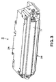
- FIG. 3 is a schematic perspective view of the cartridge 20
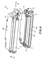
- Figure 4 is a schematic perspective view of the partially disassembled cartridge 20.
- the yellow Y, magenta M, cyan C, and black K cartridges 20Y, 20M, 20C, and 20K are identical in structure.
- the cartridge 20 is separable into a photosensitive drum unit 20A (which hereinafter will be referred to simply as "drum unit 20A") and a development unit 20B.
- the drum unit 20A comprises the photosensitive drum 21, charging means 22, and cleaning means 24.
- the development unit 20B comprises the developing means 25 for developing an electrostatic latent image formed on the photosensitive drum 21.
- the drum unit 20A has a drum frame 26, to which the electrophotographic photosensitive drum 21 is rotatably attached, with the interposition of a pair of bearings (unshown).
- the charge roller 22 as the primary charging means for uniformly charging the peripheral surface of the photosensitive drum 21, and a cleaning blade 24a for removing the residual developer (toner), that is, the developer (toner) remaining on the peripheral surface of the photosensitive drum 21, are disposed.
- the residual toner removed from the peripheral surface of the photosensitive drum 21 by the cleaning blade 24a is sent by a toner conveying mechanism 24b to a waste toner chamber 24c located in the rear portion of the drum frame 26.
- the photosensitive drum 21 is rotated in the counterclockwise direction (indicated by arrow mark a in Figure 2 ) by a motor (unshown) in synchronism with the progression of an image forming operation.
- the development unit 20B has a developer container 27, which includes a developing chamber 27a provided with a developing roller 25a rotatable in a direction indicated by an arrow b by contact with the drum 21 and a toner container 27b containing a developer (toner).
- the development roller 25a is rotatably supported by the developing means container 27a, with the interposition of a pair of bearing members 75 and 76.
- a developer (toner) supply roller 25b which is rotated in the direction indicated by an arrow mark c, in contact with the development roller 25a, and the development blade 23, are located.
- a stirring member 28 (which hereinafter may be referred to as “toner conveying member") for conveying the toner in the toner container 27b to the toner supply roller 25b while stirring the toner is disposed.
- the development unit 20B is connected to the photosensitive drum unit 20A with the use of a pair of pins 29 inserted in the holes 77 of the bearing members 75 and 76 attached to the lengthwise ends of the development unit 20B, one for one, being enabled to oscillatorily move relative to the photosensitive drum unit 20A about the axial lines of the holes 77 (pins 29). Further, the development unit 20B is kept pressured by a pair of compression springs 24d so that the development roller 25a is kept in contact with the photosensitive drum 21 by the torque generated by the pair of compression springs 24d in the direction to rotate the development unit 20B about the axial lines of the holes 77 and pins 29.
- Each photosensitive drum 21 (21Y, 21M, 21C, 21K) comprises an aluminum cylinder, and a layer of organic photoconductive substance coated on the peripheral surface of the aluminum cylinder.
- the photosensitive drum 21 is placed in the drum frame 26, being supported by the drum frame 26.
- the drum unit 20A and the development unit 20B are integrally joined with each other, forming thereby the process cartridge 20.
- Each cartridge 20 (20Y, 20M, 20C, and 20K) is removably supported by the printer main assembly 100, being enabled to be easily replaced as the service life of the photosensitive drum 21 therein expires, or the developer therein is depleted.
- the charge roller 2 (2Y, 2M, 2C, and 2K) as a charging means is of a contact type. That is, the charge roller 2 is an electrically conductive roller, and is placed in contact with the peripheral surface of the photosensitive drum 21, so that as voltage is applied to the charge roller 22, the peripheral surface of the photosensitive drum 21 is uniformly charged.
- the process for exposing the photosensitive drum 21 is carried out by a scanner as an exposing means 50.
- the scanner in this embodiment has two polygon mirrors (52YM and 52CK) although the image forming apparatus is provided with the four image formation stations PY, PM, PC, and PK.
- image formation signals are sent to a laser diode
- the laser diode projects a beam of image formation light 51 (51Y, 51M, 51C, and 51K) modulated with the image formation signals, to the polygon mirrors 52 (52YM and 52CK), which are being rotated at a high speed, and deflect (reflect) the beam of image formation light 51.
- the beam of image formation light 51 deflected by the polygon mirrors 51 is changed in direction by a deflection (reflection) mirror 54 (54Y, 54M, 54C, and 54K), travels through the focal lens 53 (53Y, 53M, 53C, and 53K), and selectively exposes the numerous points of the peripheral surface of the photosensitive drum 21 (21Y, 21M, 21C, and 21K) which is being rotated at a predetermined peripheral velocity. As a result, an electrostatic latent image is formed on the photosensitive drum 21.
- the developing means 25 (25Y, 25M, 25C, and 25K) stores in its toner container 27b the color developer (toner) for developing an electrostatic latent image on the photosensitive drum 21, into a visible image, as described above.
- the stored developer is conveyed by the toner conveying member 28 to the toner supply roller 25b, which is being rotated in the direction (indicated by arrow mark c), with its peripheral surface being kept in contact with the peripheral surface of the development roller 25a.
- the two surfaces rub against each other, causing thereby the developer on the peripheral surface of the toner supply roller 25b to transfer onto the peripheral surface of the development roller 25a to be borne thereon.
- the toner borne on the development roller 25a reaches the development blade 23, which regulates the amount by which the toner is allowed to remain adhered to the peripheral surface of the development roller 25a, while giving the toner a desired amount of electrical charge.
- the toner on the peripheral surface of the development roller 25a is formed into a thin layer with a predetermined thickness.
- the thin layer of toner is conveyed to the development station, in which the peripheral surfaces of the photosensitive drum 21 and development roller 25a are in contact with each other, and in which the toner is made to move from the development roller 25a onto the photosensitive drum 21, by the development bias (DC voltage) applied to the development roller 25a from a power source (unshown).
- the latent image on the photosensitive drum 21 is turned into a visible image (toner image, or image formed of toner).
- the toner remaining on the peripheral surface of the development roller 25a is rubbed away from the peripheral surface of the development roller 25a by the toner supply roller 25b, and is recovered into the developing means container, in which it is mixed into the main body of the toner in the developing means container.
- a contact type developing method that is, a developing method in which the photosensitive drum 21 and development roller 25a are kept in contact with each other as they are in this embodiment
- the photosensitive drum 21 is rigid
- the development roller 25a is provided with an elastic layer.
- this elastic layer a single layer of solid rubber, a combination of a layer of solid rubber and a resin layer coated on the solid rubber layer in consideration of the charging of the toner, etc., are used.
- the intermediary transfer unit 40 comprising an intermediary transferring member 40a transfers in layers onto the intermediary transferring member 40a the toner images (visible images) formed on the photosensitive drums 21, one for one, by the developing means 25 during a color image forming operation.
- the intermediary transferring member 40a is rotated in the clockwise direction (indicated by arrow mark in Figure 1 ) at the same peripheral velocity as that of the photosensitive drum 21.
- the toner images formed on the photosensitive drums 21 are transferred onto the intermediary transferring member 40a in the primary transfer stations T1 (T1Y, T1M, T1C, and T1K), which are the contact areas between the primary transfer rollers 42 (42Y, 42M, 42C, and 42K) and intermediary transferring member 40a, respectively.
- T1Y, T1M, T1C, and T1K are the contact areas between the primary transfer rollers 42 (42Y, 42M, 42C, and 42K) and intermediary transferring member 40a, respectively.
- Each transfer roller 42 is positioned so that its peripheral surface is kept pressed against the peripheral surface of the photosensitive drum 21, with the transferring member 40a sandwiched between the two peripheral surfaces. Further, voltage is applied to the transfer roller 42.
- the portion of the intermediary transferring member 40a, which is bearing the multiple images, is moved through the secondary transfer station T2, in which the intermediary transferring member 40a is kept in contact with a secondary transfer roller 5, along with a recording medium P, while keeping a recording medium P sandwiched between the intermediary transferring member 40a and transfer roller 5.
- the toner images, different in color, on the intermediary transferring member 40a are transferred all at once in layers onto the recording medium P.
- the intermediary transferring member 40a is stretched around three rollers (shafts), that is, a drive roller 41, a counter roller 43 (roller against which secondary transfer roller 42 is kept pressed), and a tension roller 44, being thereby supported by them.
- the tension roller 44 is kept pressured outward of the loop of the intermediary transferring member 40a by the pressure applied to the lengthwise end portions of the tension roller 44 by a pair of springs, so that even if the circumferential dimension of the intermediary transferring member 40a changes due to the changes in the temperature and/or humidity in the apparatus main assembly, and/or cumulative usage of the intermediary transferring member 40a, the changes in the tension of the intermediary transferring member 40a can be absorbed.
- the recording medium feed station is a station for feeding a recording medium P into the image formation station.
- the feed station comprises a cassette 1 storing a substantial number of recording mediums P, a feed roller 2, and a pair of registration rollers 3.
- the feed roller 2 is rotationally driven in synchronism with the progression of the image forming operation, and the recording mediums P in the cassettes 1 are sequentially fed into the apparatus main assembly by the feed roller 2, while being separated. Then, each recording medium P is conveyed to the pair of registration rollers 3, which carries out, according to a predetermined sequence, the non-rotational operation, that is, the operation for keeping the recording medium P on standby, and the rotational operation, that is, the operation for releasing the recording medium P to allow the recording medium P to be conveyed toward the intermediary transferring member 40a.
- the pair of registration rollers 3 releases the recording medium P so that the recording medium P aligns with an image during the following process, that is, the image transfer process.
- the secondary transfer station T2 is provided with the secondary transfer roller 5 as described before.
- the secondary transfer roller 5 is moved by a cam (unshown), in synchronism with the transfer of color images onto the recording medium P, into the top position in which it is kept pressed against the intermediary transferring member 40a, with the recording medium P sandwiched between the secondary transfer roller 5 and intermediary transferring member 40a.
- transfer bias (voltage) is applied to the transfer roller 5.
- the toner images on the intermediary transferring member 40a are transferred onto the recording medium P.
- the intermediary transferring member 40a and secondary transfer roller 5 are individually driven. Therefore, the recording medium P is conveyed in the leftward direction of the drawing, at a predetermined speed, while remaining pinched between the intermediary transferring member 40a and transfer roller 5 so that the toner images are transferred onto the recording medium P. Then, the recording medium P is further conveyed to the fixation station, in which the next process is carried out.
- the fixation station 60 is a station in which the toner images which have just been transferred onto the recording medium P are fixed.
- the fixation station 60 comprises: a film guide unit 61 containing a ceramic heater 63 for heating the recording medium P, and a pressure roller 62 for keeping the recording medium P pressed against the film guide unit 61.
- the transfer medium P bearing the transferred toner images is conveyed by the film guide unit 61 and pressure roller 62, while heat and pressure are applied to the recording medium P. As a result, the toner images are fixed to the recording medium P.
- the feed roller 2 shown in Figure 1 is rotated to separate one of the recording mediums P in the cassette 17 from the rest, and the separated recording medium P is conveyed to the pair of registration rollers 3.
- the photosensitive drum 21 and intermediary transferring member 40a are rotated (in the direction indicated by an arrow mark) at a predetermined peripheral velocity (process speed).
- the latent image is developed.
- the above described image formation steps are carried out to form yellow, magenta, cyan, and black images in the listed order.
- the formed yellow, magenta, cyan, and black toner images are transferred onto the intermediary transferring member 40a by the corresponding primary transfer rollers 42 (42Y, 42M, 42C, and 42K), in the primary transfer stations T1 (T1Y, T1M, TC1, and TK1), respectively.
- a full-color image made up of four different toners (yellow, magenta, cyan, and black toners) is formed on the surface of the intermediary transferring member 40a.
- Figure 5 is a schematic side view of the development unit 20B as seen from the direction of one of the lengthwise ends of the development unit 20B
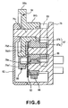
- Figure 6 is a schematic sectional view of the lengthwise end of the development unit 20B shown in Figure 5
- Figure 7 is a perspective view of the partially disassembled development unit 20B, showing the general structure thereof.
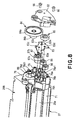
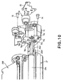
- Figures 8 - 10 are perspective views of the partially disassembled lengthwise end portion of the development unit 20B, shown in Figure 5 , different in disassembly stage and perspective.
- the development unit 20B has the main frame 27 and pair of bearing members 75 and 76.
- the development unit frame 27 comprises the developing means container 27a, and the toner container 27b which stores toner.
- the bearing members 75 and 76 are located at the lengthwise ends of the developing means container 27a, one for one, to support the development roller 25a and toner supply roller 25b.
- the development unit 20B is provided with an end cover 82 as a first end cover, bearing member 76 as a first bearing member, and a supporting member 83, which are attached to the same lengthwise end of the main frame 27 of the development unit 20B. Further, the development unit 20B is provided with a gear train which is for driving the development roller 25a, toner supply roller 25b, and toner conveying member 28 by receiving driving force from a gear (unshown) of the apparatus main assembly, and which is attached to the same lengthwise end of the frame 27 as the aforementioned end to which the end cover 82, etc., are attached.
- a gear train which is for driving the development roller 25a, toner supply roller 25b, and toner conveying member 28 by receiving driving force from a gear (unshown) of the apparatus main assembly, and which is attached to the same lengthwise end of the frame 27 as the aforementioned end to which the end cover 82, etc., are attached.
- the driving force reception gear 84 for receiving driving force from the apparatus main assembly B a development roller gear 85 with which one (which hereinafter will be referred to as first lengthwise end) of the lengthwise ends of the development roller 25a is fitted, a toner supply roller gear 86 with which the first lengthwise ends of the toner supply roller 25b is fitted, first driving force transmission gear 87, second driving force transmission gear 88, and a toner conveying member gear 89 with which the first lengthwise end of the toner conveying member 28 is fitted, are located at the aforementioned first lengthwise end of the development unit 20B.
- the driving force reception gear 84 comprises a first driving force receiving portion 84a, and a second driving force receiving portion 84b.
- the first driving force transmission gear 87 comprises a first driving force transmitting portion 87a and a second driving force transmitting portion 87b.
- the bearing member 76 has holes 76a and 76b, through which the aforementioned lengthwise end portion 25a1 of the shaft of the development roller 25a, and the aforementioned lengthwise end portion 25b1 of the shaft of the toner supply roller 25b, are put to be rotatably supported by the bearing member 76 ( Figure 10 ). Further, the bearing member 76 has gear shafts 76c, 76d, and 76e around which the driving force reception gear 84, first driving force transmission gear 87, and second driving force transmission gear 88, are fitted to be rotatably supported. In addition, the bearing member 76 has positioning projections 76h and 76i which are fitted into the holes of a regulating member 83.
- the toner conveying member gear 89 is fitted around a toner conveying member gear shaft 90 rotatably supported by the development unit main frame 27.
- the driving force reception gear 84 of the development unit 20B receives driving force from the apparatus main assembly B, and transmits the driving force to the development roller 25a, toner supply roller 25b, and toner conveying member 28.
- the transmission of the driving force from the driving force reception gear 84 to the development roller 25a is accomplished by the meshing of the driving force receiving portion 84a of the driving force reception gear 84 with the development roller gear 85.
- the driving force transmission gear portion 84b is engaged with the second transmission gear portion 87b.
- the first transmission gear portion 87a is engaged with the toner feeding member gear 89 to transmit the driving force.
- the supporting member 83 is located at the aforementioned first lengthwise end of the development unit 20B. It is positioned outward of the first driving force transmission gear 87 for transmitting driving force to the toner supply roller 25b. Further, it is positioned outward of the second driving force transmission gear 88 and toner supply roller gear 86.
- the regulating member 83 in this embodiment is a piece of metallic plate such as steel plate. Obviously, the regulating member 83 does not need to be made of steel plate; it may be made of resin, FRP (fiber-reinforced plastic), or the like.
- the supporting member 83 is provided with positioning holes 83a and 83b into which the positioning projections 76h an 76i of the bearing member 76 are fitted, holes 83c and 83d into which the end portions 76d1 and 76e1 of the gear shafts 76d and 76e for supporting the first and second driving force transmission gears 87 and 88 are fitted, and hole 83e into which an elastic claw 76k, as the supporting member retaining member, of the bearing member 76 engages.
- the supporting member 83 is precisely positioned relative to the development unit main frame 27, as the positioning projections 76h and 76i of the bearing member 76 are fitted into the positioning holes 83a and 83b of the supporting member 83.
- the holes 83c and 83d of the regulating member (supporting member) 83 the end portions 76d1 and 76e1 of the bearing member 76 fit into them, one for one.
- the gear shaft 76d for supporting the first driving force transmission gear 87 cannot be supported by the shaft attached to the end cover 82, because of the presence of the driving force reception gear 84 between the first driving force transmission gear 87 and end cover 82. However, the end portion of the gear shaft 76d is fitted in the hole of the supporting member 83, being thereby prevented from wobbling when driving force is transmitted to the first driving force transmission gear 87.
- the gear shaft 76e for supporting the second driving force transmission gear 88 no gear is present between it and the end cover 82, and therefore, it is supported by the gear shaft 76e supported by the supporting member 83 and end cover 82.
- the second driving force transmission gear 88 may be supported by a gear shaft attached to only one of the supporting member 83 and end cover 82.
- the elastic claw 76k (supporting member retaining portion) of the bearing member 76 is fitted in the hole 83e of the supporting member 83, making it thereby difficult for the supporting member 83 to become separated from the bearing member 76.
- the supporting member 83 is sandwiched between the bearing member 76 and end cover 82; parts (portions surrounding positioning holes) of the supporting member 83 are placed in contact with the end cover 82, keeping thereby the supporting member 83 kept pressed on the bearing member 76.
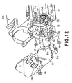
- Figures 11 and 12 are schematic perspective views, different in perspective, of the partially disassembled second lengthwise end portion of the development unit 20B, depicting the bearing member 75 (second bearing member) and end cover 81 (second end cover) located at the second lengthwise end of the development unit 20B.
- the first lengthwise end portion of the developing means container 27a of the development unit main frame 27 is provided with positioning holes 71a and 71b, and screw holes 71c and 71d. Further, the bearing member 76 is provided with positioning projections 76m and 76n ( Figure 10 ), which fit into the positioning holes 71a and 71b of the developing means container 27a.
- the projections 76m and 76n are fitted into the holes 71a and 72b, accurately positioning the bearing member 76 relative to the developing means container 27a. Then, the bearing member 76 is screwed to the developing means container 27a with the use of screws 93 and 94. The screws 93 and 94 are put through the through holes 76p and 76q, and screwed into the screw holes 71c and 71d of the developing means container 27a, solidly fixing the bearing member 76 to the developing means container 27a.
- the toner supply roller gear 86 is fitted around the first lengthwise end portion 25b1 of the shaft of the toner supply roller 25b (toner conveying gear attachment process).
- the first driving force transmission gear 87 is fitted around the gear shaft 76d of the bearing member 76, being rotatably supported by the bearing member 76 (gear shaft 76d).
- the first driving force transmitting portion 87a of the first driving force transmission gear 87 meshes with the toner conveying member gear 79.
- the second driving force transmission gear 88 is fitted around the gear shaft 76e of the bearing member 76, being rotatably supported by the bearing member 76 (gear shaft 76e). Further, the second driving force transmission gear 88 meshes with the second driving force transmitting portion 87b of the first driving force transmission gear 87, and the toner supply roller gear 86.
- the supporting member 83 is accurately positioned relative to the bearing member 76, as the positioning projections 76h and 76i of the bearing member 76 fit into the positioning holes 83a and 83b of the supporting member 83. Further, the end portion 76d1 of the gear shaft 76d of the bearing member 76, and the end portion of the gear shaft 76e of the bearing member 76, fit into the positioning holes 83c and 83d of the supporting member 83, preventing thereby the gear shafts 76d and 76e from wobbling when driving force is transmitted, and also, assuring that the distance between the rotational axes of the gear 88 and 87 is kept constant (second gear attachment process, and third gear attachment process).
- the first driving force transmission gear 87 and second driving force transmission gear 88, and toner supply roller gear 86 are at least partially covered by the supporting member 83. Further, as the supporting member 83 is brought to the bearing member 76 to be attached to the bearing member 76, the craw 76k of the bearing member 76 is elastically bent, and then, snaps into the hole 83e of the supporting member 83, firmly holding the supporting member 83 to the bearing member 76 while making it thereby difficult for the supporting member 83 to become separated from the bearing member 76. Therefore, it is unlikely for the first driving force transmission gear 87, second driving force transmission gear 88, and toner supply roller gear 86 to become disengaged from the bearing member 76 (supporting member attachment process).
- the development roller gear 85 is fitted around the aforementioned shaft 25a1, and the driving force reception gear 84 is fitted around the gear shaft 76c of the bearing member 76, being thereby rotatably supported by the bearing member 76 (gear shaft 76c) (first gear attachment process).
- the development roller gear 85 meshes with the first driving force receiving portion 84a of the driving force reception gear 84, and the second driving force receiving portion 84b of the driving force reception gear 84 meshes with the second driving force transmitting portion 87b of the first driving force transmission gear 87.
- the positioning projections 76h and 76i of the bearing member 76 are fitted into the positioning holes 82a and 82b of the end cover 82, accurately positioning thereby the end cover 82 relative to the bearing member 76.
- the end cover 82 is screwed to the bearing member 76 with the use of the screws 95 and 96 (cover attachment process).
- the screws 95 and 96 are put through the through holes 82c and 82d of the end cover 82, and screwed into the screw holes 76r and 76s of the bearing member 76, securely fixing the end cover 82 to the bearing member 76.
- the second end portion 25a2 and second end portion 25b2 of the shafts of the development roller 25a and toner supply roller 25b, respectively, are put through the holes 75a and 75b of the bearing member 75, being thereby rotatably supported by the bearing member 75.
- the positioning projections 75m and 75n of the bearing member 75 are fitted into the positioning holes 71e and 71f of the development unit main frame 27 located at the second lengthwise end of the development unit main frame 27.
- the bearing member 75 is accurately positioned relative to the developing means container 27a. Thereafter, the bearing member 75 is screwed to the development unit main frame 27 with the use of the screws 97 and 98.
- the screws 97 and 98 are put through the through holes 75p and 75q of the bearing member 75, and screwed into the screw holes 71g and 71h of the development unit main frame 27, securely fixing the bearing member 75 to the developing means container 27a.
- the positioning projections 75h and 75i of the bearing member 75 are put, accurately positioning the end cover 81 relative to the bearing member 75. Then, the end cover 81 is screwed to the development unit main frame 27 with the use of the screw 99. The screw 99 is put through the through hole 81p of the end cover 81, and screwed into the screw hole of the development unit main frame 27, securely fixing the end cover 81 to the development unit main frame 27.
- the regulating member 83 is mounted to the one end bearing member 76 by engagement of the gear shaft holes 83c, 83d of the regulating member 83 with the gear shaft 76d (shaft end portion 76d1) of the first driving force transmission gear 87 and the gear shaft 76e (shaft end portion 76e1) of the second driving force transmission gear 88, and by engagement of the positioning holes 83a, 83b of the regulating member 83 with positioning projections 76h, 76i of the one end bearing member 76.
- the method further comprises (D) an one end covering member mounting step of mounting the one end covering member 82 to the one end bearing member 76 so as to interpose the regulating member 83 therebetween and to partly contacted to the regulating member 83 to confine the regulating member 83 to the one end bearing member 76.
- the one end covering member 82 is engaged with the positioning projections 76h, 76i to determine the mounting position relative to the one end bearing member 76.
- the regulating member 83 may be locked with the locking hole 83e of the regulating member 83 such that locking portion 76k provided on the one end bearing member 76 is elastically locked.
- the assemblying method may further comprises a toner feeding member gear mounting step, prior to the roller mounting step, of mounting the toner feeding member gear 89 for transmitting the driving force received from the main assembly of the apparatus to the toner feeding member 28 for feeding the developer accommodated in the developer accommodating portion 27b at the one longitudinal end of the developing device frame 27.
- the assemblying method further comprises, after the regulating member mounting step, a driving force reception gear mounting step of mounting the driving force reception gear 84 for receiving the driving force from the main assembly of the apparatus when the process cartridge 20 is mounted to the main assembly of the apparatus to the gear shaft 76c provided on the one end bearing member 76, and a developing roller gear mounting step of mounting the developing roller gear 85 for transmitting driving force received from the main assembly of the apparatus by the driving force reception gear 84 to the developing roller 25a, wherein after the driving force reception gear 84 and the developing roller gear 85 are mounted to the one end bearing member 76, the one end covering member 82 is mounted to the one end bearing member 76.
- the present invention offers the following effects.
- the supporting member at least partially covers the first driving force transmission gear, second driving force transmission gear, and developer supply roller gear, and is attached to the first bearing member, preventing thereby these gears from accidentally falling off. Therefore, more latitude is afforded in terms of the cartridge attitude during the assembly thereof, as well as the order in which the cartridge assembly processes are carried out, improving thereby process cartridge assembly efficiency.
- the present invention makes it possible to reduce the size of a process cartridge. It also makes it possible to precisely support the second gear for transmitting the driving force received by the first gear to the development supply roller. Further, it improves process cartridge assembly efficiency.
Landscapes
- Engineering & Computer Science (AREA)
- Computer Vision & Pattern Recognition (AREA)
- Physics & Mathematics (AREA)
- General Physics & Mathematics (AREA)
- Life Sciences & Earth Sciences (AREA)
- Manufacturing & Machinery (AREA)
- Sustainable Development (AREA)
- Electrophotography Configuration And Component (AREA)
- Dry Development In Electrophotography (AREA)
Applications Claiming Priority (2)
| Application Number | Priority Date | Filing Date | Title |
|---|---|---|---|
| JP2003400799A JP4086766B2 (ja) | 2003-11-28 | 2003-11-28 | プロセスカートリッジ及びプロセスカートリッジ組立方法 |
| JP2003400799 | 2003-11-28 |
Publications (3)
| Publication Number | Publication Date |
|---|---|
| EP1580622A2 EP1580622A2 (en) | 2005-09-28 |
| EP1580622A3 EP1580622A3 (en) | 2005-10-05 |
| EP1580622B1 true EP1580622B1 (en) | 2012-02-22 |
Family
ID=34616673
Family Applications (1)
| Application Number | Title | Priority Date | Filing Date |
|---|---|---|---|
| EP04015345A Expired - Lifetime EP1580622B1 (en) | 2003-11-28 | 2004-06-30 | Process cartridge and assemblying method therefor |
Country Status (5)
| Country | Link |
|---|---|
| US (1) | US7027756B2 (enExample) |
| EP (1) | EP1580622B1 (enExample) |
| JP (1) | JP4086766B2 (enExample) |
| KR (1) | KR100644307B1 (enExample) |
| CN (1) | CN100367132C (enExample) |
Families Citing this family (39)
| Publication number | Priority date | Publication date | Assignee | Title |
|---|---|---|---|---|
| JP3997817B2 (ja) * | 2002-04-02 | 2007-10-24 | ブラザー工業株式会社 | 現像装置および画像形成装置 |
| EP1630622A3 (en) * | 2004-08-30 | 2006-09-06 | Seiko Epson Corporation | Developing device, image forming apparatus, and image forming system |
| WO2006070904A1 (en) * | 2004-12-28 | 2006-07-06 | Canon Kabushiki Kaisha | Charging member, process cartridge and electrophotographic apparatus |
| JP4239100B2 (ja) * | 2005-01-31 | 2009-03-18 | ブラザー工業株式会社 | 現像カートリッジ及び画像形成装置 |
| JP4280753B2 (ja) * | 2005-04-27 | 2009-06-17 | キヤノン株式会社 | 電子写真画像形成装置及びプロセスカートリッジ |
| JP4684732B2 (ja) * | 2005-04-27 | 2011-05-18 | キヤノン株式会社 | 電子写真画像形成装置およびプロセスカートリッジ |
| KR20070095491A (ko) * | 2005-09-22 | 2007-10-01 | 삼성전자주식회사 | 현상유닛 및 이를 가지는 화상형성장치 |
| JP4667444B2 (ja) | 2006-12-13 | 2011-04-13 | キヤノン株式会社 | 電子写真画像形成装置 |
| US7856192B2 (en) * | 2006-12-28 | 2010-12-21 | Canon Kabushiki Kaisha | Process cartridge and electrophotographic image forming apparatus |
| JP5084257B2 (ja) * | 2006-12-28 | 2012-11-28 | キヤノン株式会社 | プロセスカートリッジ及びこれを用いた画像形成装置 |
| JP4280772B2 (ja) | 2006-12-28 | 2009-06-17 | キヤノン株式会社 | プロセスカートリッジ及び電子写真画像形成装置 |
| JP5094186B2 (ja) * | 2007-04-10 | 2012-12-12 | キヤノン株式会社 | プロセスカートリッジ及び電子写真画像形成装置 |
| JP4968957B2 (ja) | 2008-03-31 | 2012-07-04 | キヤノン株式会社 | 枠体ユニット、現像装置及びプロセスカートリッジ、並びに、枠体ユニット、現像装置及びプロセスカートリッジの製造方法 |
| JP5344538B2 (ja) * | 2008-05-27 | 2013-11-20 | キヤノン株式会社 | プロセスカートリッジの組立て方法、プロセスカートリッジの分解方法、プロセスカートリッジの再生産方法及びプロセスカートリッジ |
| JP4562206B2 (ja) * | 2008-09-29 | 2010-10-13 | キヤノン株式会社 | 電子写真画像形成装置 |
| JP2011186447A (ja) * | 2010-02-15 | 2011-09-22 | Canon Inc | 現像装置及びプロセスカートリッジ |
| JP5517732B2 (ja) | 2010-05-11 | 2014-06-11 | キヤノン株式会社 | プロセスカートリッジ及び画像形成装置 |
| JP5539038B2 (ja) | 2010-06-02 | 2014-07-02 | キヤノン株式会社 | 電子写真画像形成装置 |
| JP5106656B2 (ja) | 2010-06-22 | 2012-12-26 | キヤノン株式会社 | プロセスカートリッジ及び画像形成装置 |
| JP4846062B1 (ja) | 2010-08-20 | 2011-12-28 | キヤノン株式会社 | カートリッジ及び画像形成装置 |
| JP5392302B2 (ja) * | 2011-06-10 | 2014-01-22 | ブラザー工業株式会社 | 現像カートリッジ |
| JP5348209B2 (ja) | 2011-08-31 | 2013-11-20 | ブラザー工業株式会社 | カートリッジ |
| JP5413428B2 (ja) | 2011-08-31 | 2014-02-12 | ブラザー工業株式会社 | カートリッジ |
| JP5413427B2 (ja) | 2011-08-31 | 2014-02-12 | ブラザー工業株式会社 | 画像形成装置 |
| JP5182402B2 (ja) | 2011-08-31 | 2013-04-17 | ブラザー工業株式会社 | カートリッジ |
| JP5348211B2 (ja) | 2011-08-31 | 2013-11-20 | ブラザー工業株式会社 | 現像カートリッジ |
| CN103917922B (zh) | 2011-11-09 | 2017-11-17 | 佳能株式会社 | 盒和单元 |
| JP2013122489A (ja) | 2011-11-09 | 2013-06-20 | Canon Inc | カートリッジ及びユニット |
| TWI747249B (zh) | 2012-06-15 | 2021-11-21 | 日商佳能股份有限公司 | 製程卡匣 |
| JP6057651B2 (ja) | 2012-10-01 | 2017-01-11 | キヤノン株式会社 | プロセスカートリッジおよびプロセスカートリッジの製造方法 |
| CN105334711B (zh) * | 2014-07-25 | 2019-06-11 | 纳思达股份有限公司 | 一种处理盒及图像形成装置 |
| KR102500135B1 (ko) | 2015-02-27 | 2023-02-17 | 캐논 가부시끼가이샤 | 드럼 유닛, 카트리지 및 프로세스 카트리지 |
| JP6693302B2 (ja) * | 2016-06-30 | 2020-05-13 | ブラザー工業株式会社 | 現像カートリッジ |
| JP7058992B2 (ja) | 2017-12-13 | 2022-04-25 | キヤノン株式会社 | 画像形成装置およびカートリッジ |
| JP6665243B2 (ja) * | 2017-12-15 | 2020-03-13 | 株式会社スギノマシン | ノズルの検査方法およびその装置 |
| JP2019174625A (ja) * | 2018-03-28 | 2019-10-10 | ブラザー工業株式会社 | 現像カートリッジ |
| JP7059072B2 (ja) * | 2018-03-30 | 2022-04-25 | キヤノン株式会社 | 像担持ユニットの製造方法及びカートリッジの製造方法 |
| JP7057191B2 (ja) | 2018-03-30 | 2022-04-19 | キヤノン株式会社 | 像担持ユニットの製造方法及びカートリッジの製造方法 |
| CN109272574B (zh) * | 2018-09-10 | 2020-04-10 | 武汉大学 | 基于投影变换的线阵旋转扫描相机成像模型构建方法和标定方法 |
Family Cites Families (18)
| Publication number | Priority date | Publication date | Assignee | Title |
|---|---|---|---|---|
| US5966566A (en) | 1993-03-24 | 1999-10-12 | Canon Kabushiki Kaisha | Recycle method for process cartridge and image forming apparatus |
| JPH06314001A (ja) * | 1993-04-28 | 1994-11-08 | Canon Inc | ギアユニット及び画像形成装置 |
| JP2875203B2 (ja) * | 1995-03-27 | 1999-03-31 | キヤノン株式会社 | 電子写真画像形成装置、プロセスカートリッジ、駆動力伝達部品、及び、電子写真感光体ドラム |
| JP3382474B2 (ja) | 1996-09-30 | 2003-03-04 | キヤノン株式会社 | プロセスカートリッジ及び電子写真画像形成装置及びクリーニングローラの組み込み方法 |
| JP3466888B2 (ja) * | 1997-10-01 | 2003-11-17 | キヤノン株式会社 | プロセスカートリッジ及び電子写真画像形成装置 |
| JP2000194248A (ja) | 1998-12-28 | 2000-07-14 | Canon Inc | プロセスカ―トリッジ及び帯電ユニット及び現像ユニット |
| JP3679645B2 (ja) | 1999-03-29 | 2005-08-03 | キヤノン株式会社 | プロセスカートリッジ |
| JP3513447B2 (ja) * | 1999-10-29 | 2004-03-31 | キヤノン株式会社 | プロセスカートリッジ |
| JP3413173B2 (ja) | 2000-01-05 | 2003-06-03 | キヤノン株式会社 | プロセスカートリッジ及び電子写真画像形成装置 |
| JP3720707B2 (ja) | 2000-01-19 | 2005-11-30 | キヤノン株式会社 | プロセスカートリッジ及び電子写真画像形成装置 |
| JP4250294B2 (ja) | 2000-02-16 | 2009-04-08 | キヤノン株式会社 | カラー電子写真画像形成装置及びプロセスカートリッジ |
| JP4677093B2 (ja) * | 2000-12-25 | 2011-04-27 | キヤノン株式会社 | プロセスカートリッジ |
| JP3832815B2 (ja) | 2001-01-16 | 2006-10-11 | 株式会社リコー | 駆動伝達装置、およびそれを備える画像形成装置 |
| JP3566697B2 (ja) | 2001-02-09 | 2004-09-15 | キヤノン株式会社 | プロセスカートリッジ、電子写真画像形成装置、及び、離隔機構 |
| JP4672893B2 (ja) | 2001-03-30 | 2011-04-20 | キヤノン株式会社 | 現像剤補給容器、及び画像形成装置 |
| JP3890227B2 (ja) | 2001-12-21 | 2007-03-07 | キヤノン株式会社 | プロセス手段移動機構、帯電装置、プロセスカートリッジ及び電子写真画像形成装置 |
| JP4011930B2 (ja) | 2002-02-20 | 2007-11-21 | キヤノン株式会社 | 現像剤容器、現像装置、プロセスカートリッジおよび画像形成装置 |
| JP3720802B2 (ja) * | 2002-11-06 | 2005-11-30 | キヤノン株式会社 | プロセスカートリッジの再生産方法 |
-
2003
- 2003-11-28 JP JP2003400799A patent/JP4086766B2/ja not_active Expired - Fee Related
-
2004
- 2004-06-29 US US10/878,616 patent/US7027756B2/en not_active Expired - Lifetime
- 2004-06-30 EP EP04015345A patent/EP1580622B1/en not_active Expired - Lifetime
- 2004-06-30 CN CNB2004100626172A patent/CN100367132C/zh not_active Expired - Fee Related
- 2004-06-30 KR KR1020040049854A patent/KR100644307B1/ko not_active Expired - Fee Related
Also Published As
| Publication number | Publication date |
|---|---|
| CN1621971A (zh) | 2005-06-01 |
| EP1580622A2 (en) | 2005-09-28 |
| JP4086766B2 (ja) | 2008-05-14 |
| JP2005164751A (ja) | 2005-06-23 |
| EP1580622A3 (en) | 2005-10-05 |
| US7027756B2 (en) | 2006-04-11 |
| US20050117935A1 (en) | 2005-06-02 |
| KR20050052322A (ko) | 2005-06-02 |
| CN100367132C (zh) | 2008-02-06 |
| KR100644307B1 (ko) | 2006-11-15 |
Similar Documents
| Publication | Publication Date | Title |
|---|---|---|
| EP1580622B1 (en) | Process cartridge and assemblying method therefor | |
| EP1580618B1 (en) | Remanufacturing method for process cartridge | |
| EP1536297B1 (en) | Process cartridge, mounting method of electrophotographic photosensitive drum and replacing method of the photosensitive drum | |
| EP1522905B1 (en) | Process cartridge and electrophotographic image forming apparatus | |
| JP4444997B2 (ja) | プロセスカートリッジ及び電子写真画像形成装置 | |
| US8687994B2 (en) | Cartridge with roller shaft having an exposed electroconductive portion | |
| EP1336905B1 (en) | Stable mounting of a process cartridge and electrophotographic image forming apparatus | |
| US7450877B2 (en) | Process cartridge and electrophotographic image forming apparatus | |
| EP1536296B1 (en) | Process cartridge, positioning mechanism therefor and electrophotographic image forming apparatus | |
| US20140169835A1 (en) | Image forming apparatus | |
| JP2004012523A (ja) | 現像装置及び現像カートリッジ及びプロセスカートリッジ及び画像形成装置 | |
| CN101551619A (zh) | 组装盒的方法及重新组装盒的方法 | |
| JP2010033086A (ja) | プロセスカートリッジ及び電子写真画像形成装置 | |
| JP2005091792A (ja) | プロセスカートリッジ及び画像形成装置 | |
| JP2004037913A (ja) | 現像装置、現像カートリッジ、プロセスカートリッジ及び画像形成装置 | |
| JP2005140898A (ja) | 現像装置、プロセスカートリッジ及び現像装置の組立方法 |
Legal Events
| Date | Code | Title | Description |
|---|---|---|---|
| PUAI | Public reference made under article 153(3) epc to a published international application that has entered the european phase |
Free format text: ORIGINAL CODE: 0009012 |
|
| PUAL | Search report despatched |
Free format text: ORIGINAL CODE: 0009013 |
|
| 17P | Request for examination filed |
Effective date: 20040630 |
|
| AK | Designated contracting states |
Kind code of ref document: A2 Designated state(s): AT BE BG CH CY CZ DE DK EE ES FI FR GB GR HU IE IT LI LU MC NL PL PT RO SE SI SK TR |
|
| AX | Request for extension of the european patent |
Extension state: AL HR LT LV MK |
|
| AK | Designated contracting states |
Kind code of ref document: A3 Designated state(s): AT BE BG CH CY CZ DE DK EE ES FI FR GB GR HU IE IT LI LU MC NL PL PT RO SE SI SK TR |
|
| AX | Request for extension of the european patent |
Extension state: AL HR LT LV MK |
|
| AKX | Designation fees paid |
Designated state(s): DE FR GB IT |
|
| 17Q | First examination report despatched |
Effective date: 20110121 |
|
| GRAP | Despatch of communication of intention to grant a patent |
Free format text: ORIGINAL CODE: EPIDOSNIGR1 |
|
| GRAS | Grant fee paid |
Free format text: ORIGINAL CODE: EPIDOSNIGR3 |
|
| GRAA | (expected) grant |
Free format text: ORIGINAL CODE: 0009210 |
|
| AK | Designated contracting states |
Kind code of ref document: B1 Designated state(s): DE FR GB IT |
|
| REG | Reference to a national code |
Ref country code: GB Ref legal event code: FG4D |
|
| REG | Reference to a national code |
Ref country code: DE Ref legal event code: R096 Ref document number: 602004036559 Country of ref document: DE Effective date: 20120419 |
|
| PLBE | No opposition filed within time limit |
Free format text: ORIGINAL CODE: 0009261 |
|
| STAA | Information on the status of an ep patent application or granted ep patent |
Free format text: STATUS: NO OPPOSITION FILED WITHIN TIME LIMIT |
|
| 26N | No opposition filed |
Effective date: 20121123 |
|
| REG | Reference to a national code |
Ref country code: DE Ref legal event code: R097 Ref document number: 602004036559 Country of ref document: DE Effective date: 20121123 |
|
| PGFP | Annual fee paid to national office [announced via postgrant information from national office to epo] |
Ref country code: IT Payment date: 20140604 Year of fee payment: 11 |
|
| PGFP | Annual fee paid to national office [announced via postgrant information from national office to epo] |
Ref country code: FR Payment date: 20140625 Year of fee payment: 11 |
|
| PG25 | Lapsed in a contracting state [announced via postgrant information from national office to epo] |
Ref country code: IT Free format text: LAPSE BECAUSE OF NON-PAYMENT OF DUE FEES Effective date: 20150630 |
|
| REG | Reference to a national code |
Ref country code: FR Ref legal event code: ST Effective date: 20160229 |
|
| PG25 | Lapsed in a contracting state [announced via postgrant information from national office to epo] |
Ref country code: FR Free format text: LAPSE BECAUSE OF NON-PAYMENT OF DUE FEES Effective date: 20150630 |
|
| PGFP | Annual fee paid to national office [announced via postgrant information from national office to epo] |
Ref country code: DE Payment date: 20190830 Year of fee payment: 16 Ref country code: GB Payment date: 20190627 Year of fee payment: 16 |
|
| REG | Reference to a national code |
Ref country code: DE Ref legal event code: R119 Ref document number: 602004036559 Country of ref document: DE |
|
| GBPC | Gb: european patent ceased through non-payment of renewal fee |
Effective date: 20200630 |
|
| PG25 | Lapsed in a contracting state [announced via postgrant information from national office to epo] |
Ref country code: GB Free format text: LAPSE BECAUSE OF NON-PAYMENT OF DUE FEES Effective date: 20200630 |
|
| PG25 | Lapsed in a contracting state [announced via postgrant information from national office to epo] |
Ref country code: DE Free format text: LAPSE BECAUSE OF NON-PAYMENT OF DUE FEES Effective date: 20210101 |