EP1566810B1 - Resistivenspeicheranordnung mit stabilem Schreibverfahren - Google Patents
Resistivenspeicheranordnung mit stabilem Schreibverfahren Download PDFInfo
- Publication number
- EP1566810B1 EP1566810B1 EP05250287.9A EP05250287A EP1566810B1 EP 1566810 B1 EP1566810 B1 EP 1566810B1 EP 05250287 A EP05250287 A EP 05250287A EP 1566810 B1 EP1566810 B1 EP 1566810B1
- Authority
- EP
- European Patent Office
- Prior art keywords
- memory
- voltage
- resistance value
- memory element
- recording
- Prior art date
- Legal status (The legal status is an assumption and is not a legal conclusion. Google has not performed a legal analysis and makes no representation as to the accuracy of the status listed.)
- Expired - Lifetime
Links
Images


Classifications
-
- G—PHYSICS
- G11—INFORMATION STORAGE
- G11C—STATIC STORES
- G11C13/00—Digital stores characterised by the use of storage elements not covered by groups G11C11/00, G11C23/00, or G11C25/00
- G11C13/02—Digital stores characterised by the use of storage elements not covered by groups G11C11/00, G11C23/00, or G11C25/00 using elements whose operation depends upon chemical change
-
- G—PHYSICS
- G11—INFORMATION STORAGE
- G11C—STATIC STORES
- G11C13/00—Digital stores characterised by the use of storage elements not covered by groups G11C11/00, G11C23/00, or G11C25/00
- G11C13/0002—Digital stores characterised by the use of storage elements not covered by groups G11C11/00, G11C23/00, or G11C25/00 using resistive RAM [RRAM] elements
- G11C13/0009—RRAM elements whose operation depends upon chemical change
-
- G—PHYSICS
- G11—INFORMATION STORAGE
- G11C—STATIC STORES
- G11C13/00—Digital stores characterised by the use of storage elements not covered by groups G11C11/00, G11C23/00, or G11C25/00
- G11C13/0002—Digital stores characterised by the use of storage elements not covered by groups G11C11/00, G11C23/00, or G11C25/00 using resistive RAM [RRAM] elements
- G11C13/0021—Auxiliary circuits
- G11C13/0064—Verifying circuits or methods
-
- G—PHYSICS
- G11—INFORMATION STORAGE
- G11C—STATIC STORES
- G11C13/00—Digital stores characterised by the use of storage elements not covered by groups G11C11/00, G11C23/00, or G11C25/00
- G11C13/0002—Digital stores characterised by the use of storage elements not covered by groups G11C11/00, G11C23/00, or G11C25/00 using resistive RAM [RRAM] elements
- G11C13/0021—Auxiliary circuits
- G11C13/0069—Writing or programming circuits or methods
-
- G—PHYSICS
- G11—INFORMATION STORAGE
- G11C—STATIC STORES
- G11C13/00—Digital stores characterised by the use of storage elements not covered by groups G11C11/00, G11C23/00, or G11C25/00
- G11C13/0002—Digital stores characterised by the use of storage elements not covered by groups G11C11/00, G11C23/00, or G11C25/00 using resistive RAM [RRAM] elements
- G11C13/0021—Auxiliary circuits
- G11C13/0097—Erasing, e.g. resetting, circuits or methods
-
- G—PHYSICS
- G11—INFORMATION STORAGE
- G11C—STATIC STORES
- G11C8/00—Arrangements for selecting an address in a digital store
-
- H—ELECTRICITY
- H10—SEMICONDUCTOR DEVICES; ELECTRIC SOLID-STATE DEVICES NOT OTHERWISE PROVIDED FOR
- H10B—ELECTRONIC MEMORY DEVICES
- H10B63/00—Resistance change memory devices, e.g. resistive RAM [ReRAM] devices
- H10B63/30—Resistance change memory devices, e.g. resistive RAM [ReRAM] devices comprising selection components having three or more electrodes, e.g. transistors
-
- G—PHYSICS
- G11—INFORMATION STORAGE
- G11C—STATIC STORES
- G11C13/00—Digital stores characterised by the use of storage elements not covered by groups G11C11/00, G11C23/00, or G11C25/00
- G11C13/0002—Digital stores characterised by the use of storage elements not covered by groups G11C11/00, G11C23/00, or G11C25/00 using resistive RAM [RRAM] elements
- G11C13/0004—Digital stores characterised by the use of storage elements not covered by groups G11C11/00, G11C23/00, or G11C25/00 using resistive RAM [RRAM] elements comprising amorphous/crystalline phase transition cells
-
- G—PHYSICS
- G11—INFORMATION STORAGE
- G11C—STATIC STORES
- G11C13/00—Digital stores characterised by the use of storage elements not covered by groups G11C11/00, G11C23/00, or G11C25/00
- G11C13/0002—Digital stores characterised by the use of storage elements not covered by groups G11C11/00, G11C23/00, or G11C25/00 using resistive RAM [RRAM] elements
- G11C13/0021—Auxiliary circuits
- G11C13/0069—Writing or programming circuits or methods
- G11C2013/009—Write using potential difference applied between cell electrodes
-
- G—PHYSICS
- G11—INFORMATION STORAGE
- G11C—STATIC STORES
- G11C2213/00—Indexing scheme relating to G11C13/00 for features not covered by this group
- G11C2213/10—Resistive cells; Technology aspects
- G11C2213/11—Metal ion trapping, i.e. using memory material including cavities, pores or spaces in form of tunnels or channels wherein metal ions can be trapped but do not react and form an electro-deposit creating filaments or dendrites
-
- G—PHYSICS
- G11—INFORMATION STORAGE
- G11C—STATIC STORES
- G11C2213/00—Indexing scheme relating to G11C13/00 for features not covered by this group
- G11C2213/10—Resistive cells; Technology aspects
- G11C2213/15—Current-voltage curve
-
- G—PHYSICS
- G11—INFORMATION STORAGE
- G11C—STATIC STORES
- G11C2213/00—Indexing scheme relating to G11C13/00 for features not covered by this group
- G11C2213/30—Resistive cell, memory material aspects
- G11C2213/34—Material includes an oxide or a nitride
-
- G—PHYSICS
- G11—INFORMATION STORAGE
- G11C—STATIC STORES
- G11C2213/00—Indexing scheme relating to G11C13/00 for features not covered by this group
- G11C2213/70—Resistive array aspects
- G11C2213/79—Array wherein the access device being a transistor
-
- H—ELECTRICITY
- H10—SEMICONDUCTOR DEVICES; ELECTRIC SOLID-STATE DEVICES NOT OTHERWISE PROVIDED FOR
- H10N—ELECTRIC SOLID-STATE DEVICES NOT OTHERWISE PROVIDED FOR
- H10N70/00—Solid-state devices having no potential barriers, and specially adapted for rectifying, amplifying, oscillating or switching
- H10N70/011—Manufacture or treatment of multistable switching devices
- H10N70/021—Formation of switching materials, e.g. deposition of layers
- H10N70/026—Formation of switching materials, e.g. deposition of layers by physical vapor deposition, e.g. sputtering
-
- H—ELECTRICITY
- H10—SEMICONDUCTOR DEVICES; ELECTRIC SOLID-STATE DEVICES NOT OTHERWISE PROVIDED FOR
- H10N—ELECTRIC SOLID-STATE DEVICES NOT OTHERWISE PROVIDED FOR
- H10N70/00—Solid-state devices having no potential barriers, and specially adapted for rectifying, amplifying, oscillating or switching
- H10N70/20—Multistable switching devices, e.g. memristors
- H10N70/24—Multistable switching devices, e.g. memristors based on migration or redistribution of ionic species, e.g. anions, vacancies
- H10N70/245—Multistable switching devices, e.g. memristors based on migration or redistribution of ionic species, e.g. anions, vacancies the species being metal cations, e.g. programmable metallization cells
-
- H—ELECTRICITY
- H10—SEMICONDUCTOR DEVICES; ELECTRIC SOLID-STATE DEVICES NOT OTHERWISE PROVIDED FOR
- H10N—ELECTRIC SOLID-STATE DEVICES NOT OTHERWISE PROVIDED FOR
- H10N70/00—Solid-state devices having no potential barriers, and specially adapted for rectifying, amplifying, oscillating or switching
- H10N70/801—Constructional details of multistable switching devices
- H10N70/821—Device geometry
- H10N70/826—Device geometry adapted for essentially vertical current flow, e.g. sandwich or pillar type devices
-
- H—ELECTRICITY
- H10—SEMICONDUCTOR DEVICES; ELECTRIC SOLID-STATE DEVICES NOT OTHERWISE PROVIDED FOR
- H10N—ELECTRIC SOLID-STATE DEVICES NOT OTHERWISE PROVIDED FOR
- H10N70/00—Solid-state devices having no potential barriers, and specially adapted for rectifying, amplifying, oscillating or switching
- H10N70/801—Constructional details of multistable switching devices
- H10N70/881—Switching materials
- H10N70/883—Oxides or nitrides
- H10N70/8833—Binary metal oxides, e.g. TaOx
Definitions
- the present invention relates to a memory device in which a memory cell is formed using a memory element which stores information according to a state of electric resistance.
- a high-density DRAM that performs a high-speed operation is widely used as a random access memory.
- the DRAM is a volatile memory in which information disappears when a power supply is shut off, there has been a demand for a nonvolatile memory in which information does not disappear.
- FeRAM ferroelectric memory
- MRAM magnetic memory
- phase change memory phase change memory
- resistance change type memory such as a PMC (Programmable Metallization Cell) or an RRAM.
- a phase change memory is a memory which performs the recording by applying a voltage pulse having the same polarity and different magnitude.
- phase change memory Since the phase change memory generates switching in accordance with a temperature, there remains a problem of being sensitive to a change of environmental temperature.
- a material having a characteristic that a resistance value changes by applying a voltage or current is used for a memory layer in which information is stored.
- PMC has a structure in which an ionic conductor containing a certain metal is interposed between two electrodes, and one of those two electrodes is made to contain the metal which is contained in the ionic conductor, thereby using a characteristic in which an electrical property such as a resistance or capacitance of the ionic conductor changes when the voltage is applied between the two electrodes (for example, refer to patent reference 1).
- an ionic conductor is composed of a solid solution made of chalcogenide and a metal (for example, amorphous GeS or amorphous GeSe), and one of the two electrodes contains Ag, Cu or Zn (refer to the patent reference 1).
- a crystallization temperature of amorphous GeS or amorphous GeSe is approximately 200 degrees Celsius in the PMC and the characteristic becomes deteriorated when the ionic conductor is crystallized, there is a problem that PMC can not endure a high temperature in a process of actually producing the memory element, which is a process of forming a CVD insulation film or a protection film or the like, for example.
- a voltage pulse having a different polarity is applied at the time of recording (writing) information and at the time of erasing information.
- I-V characteristic of memory layer is shown in the non-patent reference 2, and a threshold voltage when recording and erasing is set to ⁇ 0.5 volt. Even in this structure, recording and erasure of information can be performed by applying a voltage pulse, and the required pulse voltage is assumed to be ⁇ 1.1 volts and the width thereof is 2 ms.
- high speed recording and erasing can be performed, and an operation at the voltage pulse width of 100 ns is reported.
- the required pulse voltage is ⁇ 5 volts.
- each material of the memory layer which is proposed in the structure of above mentioned RRAM is a crystalline material, there occur such problems as: heat treatment of approximately 600 degrees Celsius is required, it is very difficult to manufacture the monocrystal of proposed materials, the miniaturization becomes difficult due to the reason that there is an influence of grain boundary when the polycrystal is used, and so forth.
- the fact that the resistance value after recording is thus dependent on the pulse width of the recording indicates indirectly that the resistance value will also change when the same pulse is repeatedly applied.
- the resistance value after recording changes greatly depending on the pulse width when the pulse having the same polarity is applied. That shows a characteristic in which in the case where the pulse width is 50 ns or shorter, a rate of resistance change due to the recording becomes small; and in the case where the pulse width is 100 ns or longer, the resistance value does not saturate to a constant value but conversely, the longer the pulse width becomes, the closer it comes to the resistance value before recording.
- the rate of resistance change due to the recording is small and it becomes susceptible to the dispersion in the resistance value after recording, and therefore it is difficult to perform the recording stably.
- a process of reading and confirming the contents of information (the resistance value of the memory layer) which have been already recorded in the memory element is carried out before performing the recording, and the recording is to be performed correspondingly to a relation between the confirmed contents (resistance value) and the contents to be recorded from now on (resistance value).
- a process of reading and confirming the contents of information which are recorded in the memory element is carried out after performing the recording, for example, and when there exists a difference from a desired resistance value, re-recording is performed to obtain a desired resistance value corrected.
- the period of time required for recording becomes long, and it becomes difficult to perform overwriting of data or the like at a high speed, for example.
- WO 02091385 A1 disclose a memory cell with a pair of electrodes, and an active layer sandwiched between the electrodes.
- the memory cell includes a molecular system and ionic complexes distributed in the molecular system.
- the active layer has a high-impedance state and a low-impedance state and can be switched from high-impedance state to the low-impedance state (writing) and low-impedance state to the high-impedance state (erasing) using an appropriate writing or erasing signal.
- EP 1557841 A2 discloses a memory device for which recording of multi-valued data can be performed at a high speed and the recording of multi-valued data can be performed with a drive circuit having comparatively simple configuration.
- the memory device is formed of a memory cell including a memory element which stores information according to a state of electric resistance and a MIS transistor as a load connected in series to the memory element.
- An operation to change the memory cell from a state of high resistance value to a state of low resistance value is defined as writing and an operation to change the memory cell from the state of low resistance value to the state of high resistance value is defined as erasing.
- EP 1536474 A2 discloses a memory device having an arrangement in which a memory thin film is sandwiched between first and second electrodes.
- the memory device contains at least rare earth elements and any one of elements selected from Cu, Ag, Zn and Te, S, Se.
- the memory device can record and read information with ease stably, and can be manufactured easily by a relatively simple manufacturing method.
- WO 0049659 discloses the preamble of claim 1.
- At least an embodiment of the present invention aims to provide a memory device in which recording can be performed stably and the time required for recording information can be shortened.
- a method of operating memory device according to the present invention is defined by claim 1.
- the characteristic is obtained in which the combined resistance value of the memory element and the circuit element in the memory cell after writing becomes almost a constant value irrespective of the pulse width of said voltage, so that regardless of the resistance value of the memory element before writing being high or low, the combined resistance value of the memory cell after writing becomes almost the same in both the cases.
- the writing can be performed without fail not depending on the resistance value of the memory element before writing.
- the recorded information can be detected easily from an output signal based on the combined resistance value of the memory cell, and therefore a read-out error can be prevented from occurring.
- the writing can be performed without fail and the read-out error can be prevented from occurring, such process of verification that an erasure is performed prior to the recording (writing or erasing) of information to feed back a result of the read-out to a voltage control circuit becomes unnecessary.
- the process of verification becomes unnecessary and also there is no need to apply repeatedly the voltage pulse, the writing can be performed quickly. Further, since the read-out error can be prevented from occurring, there is no need to perform the reading again. Accordingly, the recording of information or the read-out of information can be performed at a high speed.
- the memory device includes a memory cell using a resistance change type memory element.
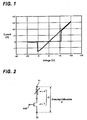
- FIG. 1 shows the change of voltage and current of the resistance change type memory element used in a memory device in an embodiment of the memory device according to the present invention.
- this resistance change type memory element is in a state where current can not flow easily, because a resistance value is large; however, when a voltage equal to or more than a writing threshold voltage (+1.1X [V] of FIG. 1 , which is several hundreds milli-volts, for example) is applied, the current flows and the resistance value is lowered.
- a writing threshold voltage (+1.1X [V] of FIG. 1 , which is several hundreds milli-volts, for example
- the memory element changes into that having Ohmic characteristic, so that a state where the current flows in proportion to the voltage is obtained.
- this resistance change type memory element has the above mentioned voltage-current characteristic, similarly to a conventional resistance change type memory element a nonvolatile memory which records 1-bit information can be obtained.
- This resistance change type memory element is the one capable of alone constituting a memory cell C of the memory device.
- the resistance change type memory element having the I-V characteristic as shown in FIG. 1 there can be listed one in which in a memory element composed of a memory layer interposed between a first electrode and a second electrode (for example, between a lower electrode and an upper electrode), the memory layer is made of an amorphous thin film such as a rare-earth oxide film.
- the film thickness of the memory layer is made to have 10 nm or less, and more preferably to have 5 nm or less.
- a metal such as Cu, Ag, or Zn which is easily ionized is contained in the rare-earth oxide film.
- an MIS transistor is particularly used for this resistance change type memory element as an active element for controlling an access to this memory element.
- an MIS transistor T is connected in series to a resistance change type memory element A to constitute the memory cell C of the memory device. Accordingly, the MIS transistor T also acts as a load to the resistance change type memory element A.
- a terminal voltage V1 is applied to a terminal of the resistance change type memory element A on the opposite side to a terminal which is connected to the MIS transistor T
- a terminal voltage V2 is applied to the other terminal (for example, on a source side) of the MIS transistor T on the opposite side to the terminal connected to the resistance change type memory element A
- a gate voltage V GS is applied to a gate of the MIS transistor T.
- an on-resistance value of the MIS transistor T is lower than the high resistance value of the resistance change type memory element A. It is more desirable that on-resistance value of the MIS transistor T is less than a fraction of the high resistance value of the resistance change type memory element A, for example, so as to become sufficiently low.
- the memory device of the present embodiment is structured so that the resistance value of the memory cell C after recording information can be almost constant irrespective of a value of the applied voltage (potential difference in FIG. 2 ) V to the memory cell C.
- FIG. 3 An electric circuit diagram of the memory device according to this embodiment is shown in FIG. 3 .
- This electric circuit diagram includes a voltage control circuit to apply each of the voltages (V1, V2 and VGS) shown in FIG. 2 .
- a memory device 100 is formed of the memory cells C of (m+1) columns and (n+1) rows disposed in matrix shape.
- the memory cell C has a structure in which one end of the resistance change type memory element A is connected to one end of the transistor T (here, a drain) as shown in FIG. 2 .
- the gate of the transistor T (T00 through Tmn) is connected to a word line W (W0 through Wm).
- the other end of the resistance change type memory element A is connected to a bit line B (B0 through Bn). Further, the other end (source) of the transistor T is connected to a source line S (S0 through Sm).
- bit line B (B0 through Bn) is connected to a bit decoder BD (BD0 through BDn) which is the voltage control circuit thereof.
- word line W (W0 through Wm) is connected to a row decoder RD (RD0 through RDm) which is the voltage control circuit thereof.
- source line S (S0 through Sm) is connected to a source decoder SD (SDO through SDm) which is the voltage control circuit thereof.
- information recording can be performed in the following manner, for example.
- the gate voltage V GS is applied by the row decoder RD to the word line W corresponding to the memory cell C on which the recording of information should be performed to turn on the gate of the MIS transistor T. Further, the terminal voltages V1 and V2 shown in FIG. 2 are applied by the bit decoder BD and the source decoder SD respectively to the bit line B and the source line S corresponding to the memory cell C. Accordingly, the voltage V can be applied to the resistance change type memory element A and the MIS transistor T in the memory cell C.
- the resistance value of the resistance change type memory element A falls from the state of high resistance and makes a transition to the state of low resistance.
- the recording (hereinafter, referred to as writing) of information (for example, data "1") can be performed on the resistance change type memory element A.
- the resistance value of the resistance change type memory element A when the resistance value of the resistance change type memory element A is in the state of low resistance, and when the gate of the MIS transistor T is turned on and the voltage V having a reverse polarity to that of writing is applied to the resistance change type memory element A and the MIS transistor T in the memory cell C, if the voltage applied to the both ends of the resistance change type memory element A is larger than the above mentioned erasure threshold voltage of the resistance change type memory element A, the resistance value of the resistance change type memory element A increases from the state of low resistance to make a transition to the state of high resistance.
- the recording (hereinafter, referred to as erasing) of information (for example, data "0") can be performed on the resistance change type memory element A.
- the gates of the MIS transistors T are turned on in all memory cells C of the same row at this time.
- the potential of the bit line B is set to be the same as the potential of the source line S or is set so that a potential difference from the source line S becomes sufficiently smaller than the threshold voltage (writing threshold voltage or erasure threshold voltage) of the resistance change type memory element A, and the recording is not performed thereon.
- the voltage V applied to the both ends of the memory cell C is divided and applied to the memory element A and the MIS transistor T.
- the voltage VA between the both ends of the memory element A decreases to a certain voltage Vmin ( ⁇ Vth)
- Vmin a certain voltage
- the decrease of the resistance value R1 of the memory element A stops and the resistance value R1 does not decrease any more. Accordingly, the voltage VA between the both ends of the memory element A also stops at the Vmin.
- the fall of the resistance value R1 of the memory element A stops in the state of having reached the I-V characteristic of the memory element A, and the voltages (VA, V-VA) which are applied between the both ends of each of the elements A and T become the constant values, respectively.
- this state is referred to as an operating point of this memory cell C.
- the recording operation (writing operation) of information stops at this operating point.
- the voltage at the both ends of each of the elements A and T and the current which flows in the memory cell C at this operating point can be obtained from the I-V characteristic of the memory element A and the I-V characteristic of the MIS transistor T.
- the applied voltage V is set such that the voltage VA applied between the both ends of the memory element A may become larger than the erasure threshold voltage of the memory element A.
- the recording (erasure) of information starts and the resistance value of the memory element A increases. Since the divided voltage to the memory element A, that is, the voltage VA applied between the both ends of the memory element A also increases along with the increase of the resistance value of the memory element A, the resistance value of the memory element A further increases. When the resistance value of the memory element A becomes large (high resistance) to some extent, the resistance value does not increase any further, so that the recording operation (erasing operation) of information stops at this point.
- the voltages at the both ends of each of the elements A and T and the current which flows in the memory cell C in this state can also be obtained from both the I-V characteristic of the memory element A and the I-V characteristic of the MIS transistor T.
- the recording of information that is, the writing or the erasure can be performed on the memory element A of that memory cell C.
- the resistance value of the memory cell after performing the recording (writing) differs depending on the resistance value of the memory element before performing the recording. In this case, it may become difficult to read the recorded information or there may occur a read-out error.
- the recording of information can be performed without fail not depending on the resistance value of the memory element A before performing the recording.
- the voltage required for making the memory cell C into the state of high resistance can be made small.
- the resistance change type memory element A and the MIS transistor T are connected in series to form the memory cell C, and when the voltage applied to the both ends of the memory cell C is equal to or more than a certain voltage which is larger than the writing threshold voltage V th of the resistance change type memory element A, having the characteristic in which the combined resistance value of the resistance value of the resistance change type memory element A and the resistance value of the MIS transistor T in the memory cell C after performing the writing becomes almost constant irrespective of the voltage applied to the memory cell C, the combined resistance value at the both ends of the memory cell C after performing the writing becomes almost constant irrespective of the resistance value of the resistance change type memory element A before performing the writing being high resistance or low resistance; and the combined resistance value at the both ends of the memory cell C does not fall excessively.
- writing can be performed without fail not depending on the resistance value of the resistance change type memory element A before performing the recording.
- the combined resistance value of the memory cell C after performing the writing becomes almost constant, and therefore when the information which has been recorded on the memory cell C is read, the contents of the recorded information can be detected easily from the output signal based on the combined resistance value of the memory cell C. Accordingly, read-out error can be prevented from occurring.
- the writing can be performed without fail and the read-out error can be prevented from occurring, a verification process in which the erasure is performed prior to the recording (writing or erasing) of information or the read-out is performed prior to the recording (writing or erasing) of information to feed back the result of this read-out to the voltage control circuit is not required.
- the writing can be performed at a high speed. Further, since the read-out error can be prevented from occurring, the read-out does not have to be done again.
- the recording of information or the reading of information can be performed at a high speed.
- writing can be performed stably without fail.
- the on-resistance of the MIS transistor T changes depending on the gate voltage V GS
- the on-resistance of the MIS transistor T can be controlled by performing control over the gate voltage V GS appropriately in the memory device 100 of this embodiment. Accordingly, with appropriately selecting both the voltage V applied to the memory cell C and the gate voltage V GS of the MIS transistor T, the resistance value of the memory cell C which becomes almost constant after performing the writing can be controlled.
- the explanation is made with respect to the case where the resistance change type memory element having the I-V characteristic shown in FIG. 1 is used as the resistance change type memory element A to form the memory cell C of the memory device 100; however, according to the present invention it is also possible to form a memory cell of the memory device by using a resistance change type memory element of another structure.
- a resistance change type memory element having a characteristic in which the resistance falls in a wide range of voltage from the threshold voltage can be used to form a memory cell.
- the fall of the resistance value at the operating point can be restrained and also the change of the resistance value of the memory cell by the magnitude of applied voltage can be made small. Further, the resistance value of the memory cell after recording information can also be made into almost a constant resistance value by appropriately setting the resistance value of the circuit element.
- a memory cell can be formed using a resistance change type memory element having such an I-V characteristic as that of a diode in which a threshold voltage exists only at one polarity between positive and negative polarities, for example.
- the measurement result of the I-V characteristic of such resistance change type memory element is shown in FIG. 4 .
- the measurement is made in FIG. 4 with limiting a current to -1.0 mA so that current beyond that can not flow, the current of -1.0 mA is applied even in a voltage range in which the current higher than that flows naturally.
- the resistance change type memory element whose I-V characteristic is shown in FIG. 4 has a characteristic in which when a positive voltage is applied, there is no specific threshold value and therefore the resistance value returns from low resistance to high resistance.
- the operating point of the circuit element exists on the negative voltage side of FIG. 4 , and similarly to the case of using the memory element having the threshold voltage on both positive and negative sides, the recording operation in this case can also be performed stably by restraining the fall of the resistance value.
- a memory element 10 whose cross section is shown in FIG. 5 has been produced as mentioned hereunder.
- a TiW film of 50 nm in thickness is deposited by a sputtering method on a substrate 1 having high electrical conductivity, for example, of a silicon substrate into which a high-concentration p-type impurity is doped.
- a Cu film of 10 nm in thickness and then a GeSbTeGd film are formed as a recording auxiliary layer 3 by using magnetron sputtering equipment, and further an amorphous Gd oxide film of 5 nm in thickness is formed as a rare-earth oxide film 4 by a reactive sputtering method based on oxygen gas introduction.
- This rare-earth oxide film 4 serves as a memory layer.
- a photo resist is formed to cover the amorphous Gd oxide film, and thereafter exposure and development are performed by photolithography to form an aperture (through-hole) in the photo resist on the amorphous Gd oxide film.
- the size of the aperture (through-hole) is set to 2. ⁇ m long and 2. ⁇ m wide.
- an insulation film 5 is formed as a hard cure resist which is stable to temperature, etching and the like.
- the hard cure resist is used for the insulation film 5, because that can be formed conveniently for an experiment; and when manufacturing a product, it is preferable to use another material (silicon oxide film or the like) for the insulation film 5.
- patterning is performed by the photolithography using plasma etching equipment to obtain the upper electrode 6 of 50 ⁇ m by 50 ⁇ m in size deposited on the insulation film 5 made of the hard cure resist.
- the memory element 10 having the structure shown in FIG. 5 has been produced as the memory element 10 of a sample 1.
- the result of measurement has shown generally similar tendency to the I-V characteristic of the memory element shown in FIG. 1 , and has shown a resistance value equal to or larger than approximately 10 k ⁇ to 100 k ⁇ .in the high resistance state.
- a memory cell 30 in which a resistance element 20 (resistance value R0) is connected in series to the memory element 10 (resistance value R1) whose cross section is shown in FIG. 5 has been produced.
- the lower electrode 2 on the side of the substrate 1 of the memory element 10 is connected to the ground potential and the resistance element 20 is connected to the upper electrode 6.
- memory cells 30 in which the resistance value R0 of the resistance element 20 is set to 1 k ⁇ , 2 k ⁇ and 5 k ⁇ respectively have been produced and made to be memory cells of samples 2 through 4.
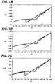
- the measurement result of the memory cell (sample 2) in which the resistance value R0 of the resistance element 20 is set to 1 k ⁇ is shown in FIG. 7A ; the measurement result of the memory cell (sample 3) in which the resistance value R0 of the resistance element 20 is set to 2 k ⁇ is shown in FIG. 7B ; and the measurement result of the memory cell (sample 4) in which the resistance value R0 of the resistance element 20 is set to 5 k ⁇ is shown in FIG. 7C .
- a resistance value Rcell combined resistance value of the memory element 10 and the resistance element 20 of the memory cell after recording the data "1" becomes an almost constant value irrespective of the change of voltage (amplitude) when an absolute value of the voltage V is larger than 0.8 volt.
- the resistance value R1 of the memory element 10 is also almost a constant value.
- FIG. 8 a horizontal axis shows a resistance value R0 of the resistance element 20, and a vertical axis shows a resistance value R1 of the memory element 10 when the resistance value of the memory cell becomes almost constant.
- the resistance value R1 of the memory element 10 after recording is determined correspondingly to the resistance value R0 of the resistance element 20 and changes almost linearly.
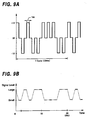
- the memory cell 30 whose circuit diagram is shown in FIG. 6 is produced; a pulse voltage of ⁇ 1 volt having a pulse width of 1 millisecond is applied in a random polarity to both ends of the memory cell 30 as shown in FIG. 9A ; and a signal level which is read out from the memory cell C has been measured by setting a read-out voltage to 0.1 volt immediately after each pulse is applied.
- a polarity pattern of the pulse voltage is set to 20 milliseconds per one cycle and is repeated.
- FIG. 9B The result of this measurement is shown in FIG. 9B .
- the magnitude of signal level is proportional to the resistance value of the memory element A, and the higher the resistance value of the memory element A is, the larger signal level can be obtained.
- the signal level corresponds to the polarity of the applied pulse voltage irrespective of the signal level before applying the pulse voltage.
- the magnitude of signal level does not change even if the voltage pulse having the same polarity is successively applied.
- the resistance value is almost constant not depending on the data pattern before performing the recording, even when the data "0" or "1" is recorded at random.
- the recording pulse width is made into 1 millisecond, because the longer the pulse width is, the more strictly data pattern dependence before recording can be evaluated; however, the similar result has also been obtained when the pulse width is short, for example, when it is 20 nanoseconds.
- FIG. 10 shows as a result of the measurement a relation between the pulse width of the pulse voltage and the combined resistance value of the memory cell 30 after recording.
- the resistance value of the memory cell 30 after recording becomes almost constant in a wide range from a pulse width of 10 -8 sec (10 nanoseconds) at the utmost left of the diagram to a pulse width of 10 -3 sec (1 millisecond) at the utmost right of the diagram.
- the recording can also be performed using the voltage pulse of short pulse width, the recording of information can be performed in a short period of time and at a high speed.
- a portion to determine the resistance value of the memory element 10 is an extremely thin region of 10 nm or less (more preferably, 5 nm or less) formed of such as the rare-earth oxide film 4 of the memory element 10 in FIG. 5 , for example, and also in the rare-earth oxide film containing a metal such as Cu, Ag, or Zn which can be easily ionized, there occurs high speed ion conduction or oxidation-reduction.
- the rare-earth oxide film is of an amorphous structure capable of operating uniformly even when processed into an extremely minute element, and furthermore a melting point thereof is high so as to operate stably against a temperature change.
- the range of desirable resistance value of the circuit element connected in series to the memory element is dependent on the I-V characteristic with respect to the voltage equal to or more than the threshold voltage of the memory element.
- the resistance value of the circuit element at least within the range between the minimum resistance value of the memory element and the maximum resistance value thereof.
- the circuit element connected in series to the memory element is not limited to the MIS transistor T or the resistance element, and an active element such as another kind of transistor or a diode can be used.
- an active element such as another kind of transistor or a diode can be used.
- a selection of memory cell can be performed by the active element.
- the verification after performing the recording of information becomes unnecessary, and therefore such an advantage that the time required for recording can be shortened to that extent can be obtained.
- the verification after recording may be performed in order to make certain that the recording of information is performed without fail in the memory device of the present invention.
- the verification can be performed as shown in flow charts of FIGS. 11A and 11B , for example.
- FIG. 11A shows a flow chart for the verification of writing.
- the writing is performed on the memory element of the memory cell.
- the verification of writing is performed in the memory cell in which the writing is performed. Specifically, a read-out operation is performed with respect to the memory cell in which the writing is performed to measure a resistance value of the memory cell.
- a step ST3 if the memory cell in which the writing is performed is in a state of being written (a state where the resistance value is a predetermined low resistance value) when measuring the resistance value of the memory cell, the writing is ended. On the other hand, when it is not in the sate of being written, it is judged that the writing has failed and the writing is again performed on the memory element of the memory cell after returning to the step ST1.
- FIG. 11B shows a flow chart for the verification of erasure.
- an erasure is performed on the memory element of the memory cell.
- the verification of erasure is performed in the memory cell to which the erasure is performed. Specifically, a read-out operation is performed with respect to the memory cell to which the erasure is performed to measure a resistance value of the memory cell.
- a step ST6 if the memory cell on which the erasure is performed is in a state of being erased (a state where the resistance value is a predetermined high resistance value) when measuring the resistance value of the memory cell, the erasure is ended. On the other hand, when it is not in the state of being erased, it is judged that the erasure has failed and the erasure is again performed on the memory element of the memory cell after returning to the step ST4.
Landscapes
- Engineering & Computer Science (AREA)
- Microelectronics & Electronic Packaging (AREA)
- Semiconductor Memories (AREA)
- Hall/Mr Elements (AREA)
- Read Only Memory (AREA)
Claims (1)
- Verfahren zum Betreiben einer Speichervorrichtung (100), wobei die Speichervorrichtung (100) Folgendes umfasst:eine Speicherzelle (30), die enthält:ein Speicherelement (100) mit einer Charakteristik, gemäß der sich ein Widerstandswert ändert, wenn zwischen beiden Enden hiervon eine Spannung angelegt wird, die gleich oder größer als eine Schwellenspannung ist,wobei das Speicherelement (10) aus einer Speicherschicht (4) gebildet ist, die zwischen eine erste und eine zweite Elektrode eingefügt ist, wobei dann, wenn zwischen der ersten und der zweiten Elektrode (2, 6) eine Spannung angelegt wird, die gleich oder größer als die Schwellenspannung ist, sich ein Widerstandswert der Speicherschicht (4) ändert, so dass sich ein Widerstandswert des Speicherelements (10) ändert; undein Schaltungselement (20) als eine mit dem Speicherelement in Reihe geschaltete Last; wobeieine Operation, um das Speicherelement (10) von einem Zustand mit hohem Widerstandswert zu einem Zustand mit niedrigem Widerstandswert zu ändern, als Schreiben definiert ist;wobei das Verfahren den Schritt des Schreibens durch Anlegen eines Spannungsimpulses zwischen beiden Enden des Speicherelements (10) und des Schaltungselements (20), der eine Amplitude besitzt, die gleich oder größer als ein bestimmter Spannungswert ist, der größer als die Schwellenspannung ist, und eine Impulsbreite im Bereich von 10-8 bis 10-3 Sekunden besitzt, umfasst;dadurch gekennzeichnet, dassdie Speicherschicht (4) des Speicherelements (10) aus einer dünnen amorphen Seltenerd-Oxidschicht gebildet ist und Cu, Ag oder Zn zu der dünnen amorphen Seltenerd-Oxidschicht hinzugefügt ist, wobei die Dicke der dünnen Schicht gleich oder kleiner als 10 nm ist, derart, dass ein kombinierter Widerstandswert des Speicherelements (10) und des Schaltungselements (20) in der Speicherzelle (30) nach der Ausführung des Schreibens unabhängig von der Impulsbreite der Spannung innerhalb des Bereichs von 10-8 bis 10-3 Sekunden ein nahezu konstanter Wert wird.
Applications Claiming Priority (2)
| Application Number | Priority Date | Filing Date | Title |
|---|---|---|---|
| JP2004022121A JP4385778B2 (ja) | 2004-01-29 | 2004-01-29 | 記憶装置 |
| JP2004022121 | 2004-01-29 |
Publications (3)
| Publication Number | Publication Date |
|---|---|
| EP1566810A2 EP1566810A2 (de) | 2005-08-24 |
| EP1566810A3 EP1566810A3 (de) | 2006-11-08 |
| EP1566810B1 true EP1566810B1 (de) | 2014-06-18 |
Family
ID=34709067
Family Applications (1)
| Application Number | Title | Priority Date | Filing Date |
|---|---|---|---|
| EP05250287.9A Expired - Lifetime EP1566810B1 (de) | 2004-01-29 | 2005-01-20 | Resistivenspeicheranordnung mit stabilem Schreibverfahren |
Country Status (6)
| Country | Link |
|---|---|
| US (1) | US7145791B2 (de) |
| EP (1) | EP1566810B1 (de) |
| JP (1) | JP4385778B2 (de) |
| KR (1) | KR101106402B1 (de) |
| CN (1) | CN100533595C (de) |
| TW (1) | TWI285895B (de) |
Families Citing this family (49)
| Publication number | Priority date | Publication date | Assignee | Title |
|---|---|---|---|---|
| JP4670252B2 (ja) | 2004-01-20 | 2011-04-13 | ソニー株式会社 | 記憶装置 |
| JP4646636B2 (ja) * | 2004-02-20 | 2011-03-09 | ルネサスエレクトロニクス株式会社 | 半導体装置 |
| JP5135406B2 (ja) * | 2004-02-20 | 2013-02-06 | ルネサスエレクトロニクス株式会社 | 半導体装置 |
| JP2006338784A (ja) | 2005-06-02 | 2006-12-14 | Sony Corp | 記憶装置及び半導体装置 |
| KR100937564B1 (ko) * | 2005-06-20 | 2010-01-19 | 후지쯔 가부시끼가이샤 | 비휘발성 반도체 기억 장치 및 그 기입 방법 |
| US7426128B2 (en) * | 2005-07-11 | 2008-09-16 | Sandisk 3D Llc | Switchable resistive memory with opposite polarity write pulses |
| WO2007046145A1 (ja) * | 2005-10-19 | 2007-04-26 | Fujitsu Limited | 不揮発性半導体記憶装置の書き込み方法 |
| JP2007184063A (ja) | 2006-01-10 | 2007-07-19 | Renesas Technology Corp | 不揮発性半導体記憶装置 |
| JP4203506B2 (ja) * | 2006-01-13 | 2009-01-07 | シャープ株式会社 | 不揮発性半導体記憶装置及びその書き換え方法 |
| JP2007294592A (ja) | 2006-04-24 | 2007-11-08 | Sony Corp | 記憶装置の駆動方法 |
| JP4742971B2 (ja) * | 2006-04-26 | 2011-08-10 | ソニー株式会社 | 記憶素子及び記憶装置 |
| WO2007132525A1 (ja) * | 2006-05-16 | 2007-11-22 | Fujitsu Limited | 不揮発性半導体記憶装置及びその書き込み方法 |
| JP4297136B2 (ja) * | 2006-06-07 | 2009-07-15 | ソニー株式会社 | 記憶装置 |
| WO2007145295A1 (ja) | 2006-06-16 | 2007-12-21 | Panasonic Corporation | 不揮発性メモリ装置 |
| JP4823316B2 (ja) * | 2006-09-05 | 2011-11-24 | 富士通株式会社 | 不揮発性半導体記憶装置の書き込み方法 |
| JP5092355B2 (ja) * | 2006-10-31 | 2012-12-05 | ソニー株式会社 | 記憶装置 |
| US7894243B2 (en) * | 2006-12-05 | 2011-02-22 | Spansion Llc | Methods of programming and erasing resistive memory devices |
| US7916523B2 (en) * | 2006-12-05 | 2011-03-29 | Spansion Llc | Method of erasing a resistive memory device |
| JP2008146740A (ja) | 2006-12-08 | 2008-06-26 | Sharp Corp | 半導体記憶装置 |
| WO2008075412A1 (ja) * | 2006-12-19 | 2008-06-26 | Fujitsu Limited | 抵抗変化素子及びその製造方法 |
| US7692999B2 (en) * | 2006-12-25 | 2010-04-06 | Semiconductor Energy Laboratory Co., Ltd | Nonvolatile memory and semiconductor device including nonvolatile memory |
| KR101080394B1 (ko) * | 2006-12-29 | 2011-11-07 | 샌디스크 코포레이션 | 비휘발성 저장장치에 대한 저항 감지 및 보상 |
| US7590002B2 (en) * | 2006-12-29 | 2009-09-15 | Sandisk Corporation | Resistance sensing and compensation for non-volatile storage |
| US7616498B2 (en) * | 2006-12-29 | 2009-11-10 | Sandisk Corporation | Non-volatile storage system with resistance sensing and compensation |
| WO2008126365A1 (ja) | 2007-03-29 | 2008-10-23 | Panasonic Corporation | 不揮発性記憶装置、不揮発性記憶素子および不揮発性記憶素子アレイ |
| US7813158B2 (en) * | 2007-05-14 | 2010-10-12 | Hong Kong Applied Science And Technology Research Institute Co., Ltd. | Recordable electrical memory |
| KR101162729B1 (ko) * | 2007-07-30 | 2012-07-05 | 삼성전자주식회사 | 전기장센서의 센싱감도향상방법, 전기장 센서를 채용한저장장치, 및 그 정보재생방법 |
| JP5012312B2 (ja) | 2007-08-15 | 2012-08-29 | ソニー株式会社 | 記憶装置の駆動方法 |
| CN101802921B (zh) | 2007-09-10 | 2013-08-28 | 松下电器产业株式会社 | 非易失性存储装置和向非易失性存储装置的数据写入方法 |
| US7965539B2 (en) * | 2007-09-28 | 2011-06-21 | Panasonic Corporation | Nonvolatile memory element, nonvolatile semiconductor memory apparatus, and reading method and writing method therefor |
| US8144509B2 (en) * | 2008-06-27 | 2012-03-27 | Qualcomm Incorporated | Write operation for spin transfer torque magnetoresistive random access memory with reduced bit cell size |
| US8331128B1 (en) | 2008-12-02 | 2012-12-11 | Adesto Technologies Corporation | Reconfigurable memory arrays having programmable impedance elements and corresponding methods |
| JP2010225221A (ja) * | 2009-03-23 | 2010-10-07 | Toshiba Corp | 半導体記憶装置 |
| US8294488B1 (en) * | 2009-04-24 | 2012-10-23 | Adesto Technologies Corporation | Programmable impedance element circuits and methods |
| US7957183B2 (en) * | 2009-05-04 | 2011-06-07 | Magic Technologies, Inc. | Single bit line SMT MRAM array architecture and the programming method |
| CN101882462A (zh) * | 2009-05-08 | 2010-11-10 | 复旦大学 | 一种电阻随机存储器的置位操作方法 |
| CN102077297A (zh) | 2009-05-14 | 2011-05-25 | 松下电器产业株式会社 | 非易失性存储装置和向非易失性存储装置写入数据的方法 |
| US8432727B2 (en) * | 2010-04-29 | 2013-04-30 | Qualcomm Incorporated | Invalid write prevention for STT-MRAM array |
| US8829482B1 (en) | 2010-09-23 | 2014-09-09 | Adesto Technologies Corporation | Variable impedance memory device structure and method of manufacture including programmable impedance memory cells and methods of forming the same |
| WO2012058324A2 (en) * | 2010-10-29 | 2012-05-03 | Rambus Inc. | Resistance change memory cell circuits and methods |
| CN103339680B (zh) | 2011-02-01 | 2016-04-13 | 松下电器产业株式会社 | 非易失性半导体存储装置 |
| KR101888468B1 (ko) * | 2011-06-08 | 2018-08-16 | 삼성전자주식회사 | Stdp 기능 셀을 위한 시냅스, stdp 기능 셀 및 stdp 기능 셀을 이용한 뉴로모픽 회로 |
| US8976568B1 (en) | 2012-01-20 | 2015-03-10 | Adesto Technologies Corporation | Circuits and methods for programming variable impedance elements |
| WO2013157261A1 (ja) * | 2012-04-20 | 2013-10-24 | パナソニック株式会社 | 不揮発性記憶素子の駆動方法および不揮発性記憶装置 |
| CN102709306B (zh) * | 2012-06-13 | 2015-02-11 | 北京大学 | 基于忆阻器和晶体管的存储器及实现多阻态的方法 |
| JP6229982B2 (ja) | 2012-11-20 | 2017-11-15 | パナソニックIpマネジメント株式会社 | 不揮発性半導体記憶装置 |
| KR102230784B1 (ko) * | 2013-05-30 | 2021-03-23 | 삼성전자주식회사 | Stdp 동작을 위한 시냅스 회로 및 시냅스 회로를 포함하는 뉴로모픽 시스템 |
| CN104746006B (zh) * | 2013-12-31 | 2017-06-06 | 北京北方微电子基地设备工艺研究中心有限责任公司 | 可调节TiW薄膜应力的TiW薄膜的磁控溅射制备工艺 |
| WO2016117134A1 (en) * | 2015-01-21 | 2016-07-28 | Nec Corporation | Reconfigurable circuit |
Citations (1)
| Publication number | Priority date | Publication date | Assignee | Title |
|---|---|---|---|---|
| WO2000049659A1 (en) * | 1999-02-17 | 2000-08-24 | International Business Machines Corporation | Microelectronic device for storing information and method thereof |
Family Cites Families (8)
| Publication number | Priority date | Publication date | Assignee | Title |
|---|---|---|---|---|
| WO2002091385A1 (en) * | 2001-05-07 | 2002-11-14 | Advanced Micro Devices, Inc. | Molecular memory cell |
| DE60130586T2 (de) * | 2001-08-13 | 2008-06-19 | Advanced Micro Devices, Inc., Sunnyvale | Speicherzelle |
| US6806526B2 (en) * | 2001-08-13 | 2004-10-19 | Advanced Micro Devices, Inc. | Memory device |
| JP4218527B2 (ja) * | 2002-02-01 | 2009-02-04 | 株式会社日立製作所 | 記憶装置 |
| US6791885B2 (en) * | 2002-02-19 | 2004-09-14 | Micron Technology, Inc. | Programmable conductor random access memory and method for sensing same |
| KR100464536B1 (ko) * | 2002-03-22 | 2005-01-03 | 주식회사 하이닉스반도체 | 자기 저항 램 |
| JP4792714B2 (ja) * | 2003-11-28 | 2011-10-12 | ソニー株式会社 | 記憶素子及び記憶装置 |
| JP4670252B2 (ja) | 2004-01-20 | 2011-04-13 | ソニー株式会社 | 記憶装置 |
-
2004
- 2004-01-29 JP JP2004022121A patent/JP4385778B2/ja not_active Expired - Fee Related
-
2005
- 2005-01-20 EP EP05250287.9A patent/EP1566810B1/de not_active Expired - Lifetime
- 2005-01-25 US US11/042,959 patent/US7145791B2/en not_active Expired - Lifetime
- 2005-01-28 CN CNB2005100697280A patent/CN100533595C/zh not_active Expired - Fee Related
- 2005-01-28 TW TW094102769A patent/TWI285895B/zh not_active IP Right Cessation
- 2005-01-28 KR KR1020050008020A patent/KR101106402B1/ko not_active Expired - Fee Related
Patent Citations (1)
| Publication number | Priority date | Publication date | Assignee | Title |
|---|---|---|---|---|
| WO2000049659A1 (en) * | 1999-02-17 | 2000-08-24 | International Business Machines Corporation | Microelectronic device for storing information and method thereof |
Also Published As
| Publication number | Publication date |
|---|---|
| KR101106402B1 (ko) | 2012-01-17 |
| TW200605076A (en) | 2006-02-01 |
| EP1566810A3 (de) | 2006-11-08 |
| JP2005216387A (ja) | 2005-08-11 |
| EP1566810A2 (de) | 2005-08-24 |
| CN100533595C (zh) | 2009-08-26 |
| CN1697081A (zh) | 2005-11-16 |
| US20050174854A1 (en) | 2005-08-11 |
| US7145791B2 (en) | 2006-12-05 |
| JP4385778B2 (ja) | 2009-12-16 |
| TWI285895B (en) | 2007-08-21 |
| KR20050077792A (ko) | 2005-08-03 |
Similar Documents
| Publication | Publication Date | Title |
|---|---|---|
| EP1566810B1 (de) | Resistivenspeicheranordnung mit stabilem Schreibverfahren | |
| US7471543B2 (en) | Storage device and semiconductor device | |
| US7457147B2 (en) | Two terminal memory array having reference cells | |
| KR101058856B1 (ko) | 기억소자 및 이를 이용한 기억장치 | |
| JP4529654B2 (ja) | 記憶素子及び記憶装置 | |
| CN100481254C (zh) | 存储装置及半导体装置 | |
| US7719873B2 (en) | Memory and semiconductor device with memory state detection | |
| US20070008770A1 (en) | Storage devices and semiconductor devices | |
| JP4465969B2 (ja) | 半導体記憶素子及びこれを用いた半導体記憶装置 | |
| US7372718B2 (en) | Storage and semiconductor device | |
| US7336520B2 (en) | Storage device and semiconductor apparatus | |
| US7382644B2 (en) | Two terminal memory array having reference cells | |
| JP5434967B2 (ja) | 記憶素子及び記憶装置 | |
| US7423902B2 (en) | Storage device and semiconductor apparatus |
Legal Events
| Date | Code | Title | Description |
|---|---|---|---|
| PUAI | Public reference made under article 153(3) epc to a published international application that has entered the european phase |
Free format text: ORIGINAL CODE: 0009012 |
|
| AK | Designated contracting states |
Kind code of ref document: A2 Designated state(s): AT BE BG CH CY CZ DE DK EE ES FI FR GB GR HU IE IS IT LI LT LU MC NL PL PT RO SE SI SK TR |
|
| AX | Request for extension of the european patent |
Extension state: AL BA HR LV MK YU |
|
| PUAL | Search report despatched |
Free format text: ORIGINAL CODE: 0009013 |
|
| AK | Designated contracting states |
Kind code of ref document: A3 Designated state(s): AT BE BG CH CY CZ DE DK EE ES FI FR GB GR HU IE IS IT LI LT LU MC NL PL PT RO SE SI SK TR |
|
| AX | Request for extension of the european patent |
Extension state: AL BA HR LV MK YU |
|
| RIC1 | Information provided on ipc code assigned before grant |
Ipc: H01L 45/00 20060101ALI20061005BHEP Ipc: G11C 13/00 20060101ALI20061005BHEP Ipc: G11C 16/02 20060101AFI20050525BHEP |
|
| 17P | Request for examination filed |
Effective date: 20070418 |
|
| AKX | Designation fees paid |
Designated state(s): DE FR GB |
|
| 17Q | First examination report despatched |
Effective date: 20080903 |
|
| GRAP | Despatch of communication of intention to grant a patent |
Free format text: ORIGINAL CODE: EPIDOSNIGR1 |
|
| INTG | Intention to grant announced |
Effective date: 20140107 |
|
| GRAS | Grant fee paid |
Free format text: ORIGINAL CODE: EPIDOSNIGR3 |
|
| GRAA | (expected) grant |
Free format text: ORIGINAL CODE: 0009210 |
|
| AK | Designated contracting states |
Kind code of ref document: B1 Designated state(s): DE FR GB |
|
| REG | Reference to a national code |
Ref country code: GB Ref legal event code: FG4D |
|
| REG | Reference to a national code |
Ref country code: DE Ref legal event code: R096 Ref document number: 602005043926 Country of ref document: DE Effective date: 20140724 |
|
| REG | Reference to a national code |
Ref country code: DE Ref legal event code: R097 Ref document number: 602005043926 Country of ref document: DE |
|
| PLBE | No opposition filed within time limit |
Free format text: ORIGINAL CODE: 0009261 |
|
| STAA | Information on the status of an ep patent application or granted ep patent |
Free format text: STATUS: NO OPPOSITION FILED WITHIN TIME LIMIT |
|
| 26N | No opposition filed |
Effective date: 20150319 |
|
| REG | Reference to a national code |
Ref country code: DE Ref legal event code: R097 Ref document number: 602005043926 Country of ref document: DE Effective date: 20150319 |
|
| REG | Reference to a national code |
Ref country code: DE Ref legal event code: R119 Ref document number: 602005043926 Country of ref document: DE |
|
| GBPC | Gb: european patent ceased through non-payment of renewal fee |
Effective date: 20150120 |
|
| PG25 | Lapsed in a contracting state [announced via postgrant information from national office to epo] |
Ref country code: GB Free format text: LAPSE BECAUSE OF NON-PAYMENT OF DUE FEES Effective date: 20150120 Ref country code: DE Free format text: LAPSE BECAUSE OF NON-PAYMENT OF DUE FEES Effective date: 20150801 |
|
| REG | Reference to a national code |
Ref country code: FR Ref legal event code: ST Effective date: 20150930 |
|
| PG25 | Lapsed in a contracting state [announced via postgrant information from national office to epo] |
Ref country code: FR Free format text: LAPSE BECAUSE OF NON-PAYMENT OF DUE FEES Effective date: 20150202 |