EP1566293B1 - Aufhängungssystem - Google Patents
Aufhängungssystem Download PDFInfo
- Publication number
- EP1566293B1 EP1566293B1 EP05002367A EP05002367A EP1566293B1 EP 1566293 B1 EP1566293 B1 EP 1566293B1 EP 05002367 A EP05002367 A EP 05002367A EP 05002367 A EP05002367 A EP 05002367A EP 1566293 B1 EP1566293 B1 EP 1566293B1
- Authority
- EP
- European Patent Office
- Prior art keywords
- lower arm
- coil spring
- seat member
- suspension system
- seat
- Prior art date
- Legal status (The legal status is an assumption and is not a legal conclusion. Google has not performed a legal analysis and makes no representation as to the accuracy of the status listed.)
- Ceased
Links
- 239000000725 suspension Substances 0.000 title description 30
- 238000005452 bending Methods 0.000 description 35
- 238000013461 design Methods 0.000 description 6
- 239000000463 material Substances 0.000 description 4
- 238000013459 approach Methods 0.000 description 3
- 239000000314 lubricant Substances 0.000 description 3
- 238000010586 diagram Methods 0.000 description 2
- 230000001747 exhibiting effect Effects 0.000 description 2
- 238000003780 insertion Methods 0.000 description 2
- 230000037431 insertion Effects 0.000 description 2
- 230000013011 mating Effects 0.000 description 2
- 238000012986 modification Methods 0.000 description 2
- 230000004048 modification Effects 0.000 description 2
- 238000005096 rolling process Methods 0.000 description 2
- 238000000926 separation method Methods 0.000 description 2
- 239000006096 absorbing agent Substances 0.000 description 1
- 238000004891 communication Methods 0.000 description 1
- 230000006835 compression Effects 0.000 description 1
- 238000007906 compression Methods 0.000 description 1
- 239000000470 constituent Substances 0.000 description 1
- 238000010276 construction Methods 0.000 description 1
- 230000000694 effects Effects 0.000 description 1
- 230000005489 elastic deformation Effects 0.000 description 1
- 230000010355 oscillation Effects 0.000 description 1
- 230000000630 rising effect Effects 0.000 description 1
- 230000035939 shock Effects 0.000 description 1
Images



Classifications
-
- B—PERFORMING OPERATIONS; TRANSPORTING
- B60—VEHICLES IN GENERAL
- B60G—VEHICLE SUSPENSION ARRANGEMENTS
- B60G7/00—Pivoted suspension arms; Accessories thereof
- B60G7/04—Buffer means for limiting movement of arms
-
- B—PERFORMING OPERATIONS; TRANSPORTING
- B60—VEHICLES IN GENERAL
- B60G—VEHICLE SUSPENSION ARRANGEMENTS
- B60G11/00—Resilient suspensions characterised by arrangement, location or kind of springs
- B60G11/14—Resilient suspensions characterised by arrangement, location or kind of springs having helical, spiral or coil springs only
- B60G11/16—Resilient suspensions characterised by arrangement, location or kind of springs having helical, spiral or coil springs only characterised by means specially adapted for attaching the spring to axle or sprung part of the vehicle
-
- B—PERFORMING OPERATIONS; TRANSPORTING
- B60—VEHICLES IN GENERAL
- B60G—VEHICLE SUSPENSION ARRANGEMENTS
- B60G3/00—Resilient suspensions for a single wheel
- B60G3/18—Resilient suspensions for a single wheel with two or more pivoted arms, e.g. parallelogram
- B60G3/20—Resilient suspensions for a single wheel with two or more pivoted arms, e.g. parallelogram all arms being rigid
- B60G3/202—Resilient suspensions for a single wheel with two or more pivoted arms, e.g. parallelogram all arms being rigid having one longitudinal arm and two parallel transversal arms, e.g. dual-link type strut suspension
-
- B—PERFORMING OPERATIONS; TRANSPORTING
- B60—VEHICLES IN GENERAL
- B60G—VEHICLE SUSPENSION ARRANGEMENTS
- B60G7/00—Pivoted suspension arms; Accessories thereof
- B60G7/001—Suspension arms, e.g. constructional features
-
- B—PERFORMING OPERATIONS; TRANSPORTING
- B60—VEHICLES IN GENERAL
- B60G—VEHICLE SUSPENSION ARRANGEMENTS
- B60G2200/00—Indexing codes relating to suspension types
- B60G2200/10—Independent suspensions
- B60G2200/14—Independent suspensions with lateral arms
- B60G2200/144—Independent suspensions with lateral arms with two lateral arms forming a parallelogram
-
- B—PERFORMING OPERATIONS; TRANSPORTING
- B60—VEHICLES IN GENERAL
- B60G—VEHICLE SUSPENSION ARRANGEMENTS
- B60G2200/00—Indexing codes relating to suspension types
- B60G2200/10—Independent suspensions
- B60G2200/14—Independent suspensions with lateral arms
- B60G2200/144—Independent suspensions with lateral arms with two lateral arms forming a parallelogram
- B60G2200/1442—Independent suspensions with lateral arms with two lateral arms forming a parallelogram including longitudinal rods
-
- B—PERFORMING OPERATIONS; TRANSPORTING
- B60—VEHICLES IN GENERAL
- B60G—VEHICLE SUSPENSION ARRANGEMENTS
- B60G2202/00—Indexing codes relating to the type of spring, damper or actuator
- B60G2202/10—Type of spring
- B60G2202/12—Wound spring
-
- B—PERFORMING OPERATIONS; TRANSPORTING
- B60—VEHICLES IN GENERAL
- B60G—VEHICLE SUSPENSION ARRANGEMENTS
- B60G2204/00—Indexing codes related to suspensions per se or to auxiliary parts
- B60G2204/10—Mounting of suspension elements
- B60G2204/12—Mounting of springs or dampers
- B60G2204/124—Mounting of coil springs
-
- B—PERFORMING OPERATIONS; TRANSPORTING
- B60—VEHICLES IN GENERAL
- B60G—VEHICLE SUSPENSION ARRANGEMENTS
- B60G2204/00—Indexing codes related to suspensions per se or to auxiliary parts
- B60G2204/10—Mounting of suspension elements
- B60G2204/12—Mounting of springs or dampers
- B60G2204/124—Mounting of coil springs
- B60G2204/1244—Mounting of coil springs on a suspension arm
-
- B—PERFORMING OPERATIONS; TRANSPORTING
- B60—VEHICLES IN GENERAL
- B60G—VEHICLE SUSPENSION ARRANGEMENTS
- B60G2204/00—Indexing codes related to suspensions per se or to auxiliary parts
- B60G2204/40—Auxiliary suspension parts; Adjustment of suspensions
- B60G2204/43—Fittings, brackets or knuckles
-
- B—PERFORMING OPERATIONS; TRANSPORTING
- B60—VEHICLES IN GENERAL
- B60G—VEHICLE SUSPENSION ARRANGEMENTS
- B60G2204/00—Indexing codes related to suspensions per se or to auxiliary parts
- B60G2204/40—Auxiliary suspension parts; Adjustment of suspensions
- B60G2204/44—Centering or positioning means
-
- B—PERFORMING OPERATIONS; TRANSPORTING
- B60—VEHICLES IN GENERAL
- B60G—VEHICLE SUSPENSION ARRANGEMENTS
- B60G2204/00—Indexing codes related to suspensions per se or to auxiliary parts
- B60G2204/40—Auxiliary suspension parts; Adjustment of suspensions
- B60G2204/45—Stops limiting travel
- B60G2204/4502—Stops limiting travel using resilient buffer
-
- B—PERFORMING OPERATIONS; TRANSPORTING
- B60—VEHICLES IN GENERAL
- B60G—VEHICLE SUSPENSION ARRANGEMENTS
- B60G2206/00—Indexing codes related to the manufacturing of suspensions: constructional features, the materials used, procedures or tools
- B60G2206/01—Constructional features of suspension elements, e.g. arms, dampers, springs
- B60G2206/10—Constructional features of arms
- B60G2206/11—Constructional features of arms the arm being a radius or track or torque or steering rod or stabiliser end link
-
- B—PERFORMING OPERATIONS; TRANSPORTING
- B60—VEHICLES IN GENERAL
- B60G—VEHICLE SUSPENSION ARRANGEMENTS
- B60G2206/00—Indexing codes related to the manufacturing of suspensions: constructional features, the materials used, procedures or tools
- B60G2206/01—Constructional features of suspension elements, e.g. arms, dampers, springs
- B60G2206/80—Manufacturing procedures
- B60G2206/81—Shaping
- B60G2206/8102—Shaping by stamping
-
- B—PERFORMING OPERATIONS; TRANSPORTING
- B60—VEHICLES IN GENERAL
- B60G—VEHICLE SUSPENSION ARRANGEMENTS
- B60G2206/00—Indexing codes related to the manufacturing of suspensions: constructional features, the materials used, procedures or tools
- B60G2206/01—Constructional features of suspension elements, e.g. arms, dampers, springs
- B60G2206/80—Manufacturing procedures
- B60G2206/82—Joining
- B60G2206/8201—Joining by welding
Definitions
- the present invention relates to a suspension system of a motor vehicle.
- motor vehicles such as minivans and wagons, generally employ in their rear suspension systems a structure in which coil springs are disposed separately from shock absorbers, or dampers, and mounted directly on lower suspension arms having an I-shaped cross section as shown in Japanese Unexamined Patent Publication No. 2002-293120 to provide as large an in-vehicle space as possible, rather than a structure in which each coil spring surrounds a damper in a coaxial configuration.
- great emphasis is placed on their performance to give a comfortable ride.
- the aforementioned Japanese Unexamined Patent Publication No. 2002-293120 proposes an independent suspension type rear suspension system employing a specially designed structure including coil springs placed between a vehicle body and left and right lower arms having an I-shaped cross section in which an upward opening dish-shaped (or recessed) coil spring seat portion is formed in each of the lower arms at about the middle of the length thereof for supporting the coil springs.
- this lower arm structure is intended to locate lower ends of the coil springs as low as possible so that the length of the coil springs can be increased. This approach is now widely taken for granted in the aforementioned kind of motor vehicles.
- each lower arm is significantly lowered due to the presence of the recessed coil spring seat portion and is greatly offset downward from a centerline of load applied by the compressive force caused by the side force acting on each lower arm and, therefore, a great downward bending force is exerted on each lower arm.
- US-A-3 069 149 discloses a coil spring suspension with an auxiliary overload bumper.
- a motor vehicle suspension comprises a helical spring disposed in compression between an upper and a lower spring seat, a depending elastic bumper attached to the upper spring seat, an upwardly extending elastic bumper attached to the lower spring seat, and a striker plate adapted to be contacted by the bumpers.
- the striker plate is fixedly attached to the helical spring between the free ends of the bumpers and normally spaced nearer the depending elastic bumper whereby the striker plate is sequentially engaged by the bumpers.
- US-A-2 455 343 discloses a universal joint construction having a first member with a ball portion, a second member having a socket and a lubricant groove extending about the socket, a lubricant fitting mounted in the second member in communication with the lubricant groove, a rubber shell formed of mating parts and mounted in the rubber shell and receiving the ball portion of the first member for relative sliding movement, the mating parts of the rubber shell being arranged with a slight space between each other.
- JP 11 217015 A discloses a lateral rod fitting structure.
- a spring seat is fixed to an upper side of a cylindrical part on each end side in the longitudinal direction of an axle housing.
- a fixing part of the lateral pin is inserted in a pin insertion hole in a side wall part suspended from an extension part to abut against a stopper part in the sidewall part.
- a lateral pin bracket is engaged between the side wall part of the spring seat and the cylindrical part of the axle housing from a lower side, and arranged parallel to the fixing part of the lateral pin inserted in the pin insertion hole in the side wall part, and the fixing part of the lateral pin is engaged with an engagement notched part.
- JP 2002 316228 A Another relevant arm having an I-shaped cross section and according to the preamble of claim 1, is disclosed in JP 2002 316228 A .
- a suspension system of the invention includes a lower arm having an I-shaped cross section disposed between a vehicle body and a wheel support member, and a coil spring which is placed between the vehicle body and a coil spring seat portion of the lower arm in a manner that the coil spring can be compressed along a vertical direction, wherein an inner end (one end) of the lower arm is attached to the vehicle body in such a way that the lower arm can swing up and down with respect to the vehicle body, while an outer end (the other) of the lower arm is attached to the wheel support member in such a way that the lower arm can swing up and down with respect to the wheel support member.
- a center of stiffness of the lower arm is located above with respect to a line, or a centerline of load applied to the lower arm, interconnecting a pivot axis of the lower arm at the inner end thereof and a pivot axis of the lower arm at the outer end thereof in such a way that the lower arm bends upward when a compressive force is applied thereto from the vehicle body and the wheel support member.
- the "center of stiffness" of any mechanical component refers to a point where that component exhibits maximum stiffness and the location of the center of stiffness of the component is determined by various factors, such as material, overall shape and cross-sectional shape of the component and how that component has been formed.
- the lower arm is not required to have so high a degree of stiffness and this makes it possible to reduce the weight of the lower arm. Also, the aforementioned structure of the suspension system makes it possible to reduce the modulus of elasticity of the coil spring and achieve an increased level of ride quality.
- FIG. 1 is a rear view showing a principal part of the suspension system A according to the preferred embodiment of the invention
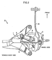
- FIG. 2 is a top view of the principal part of the suspension system A.
- the suspension system A is a wishbone-type rear suspension system which includes lower arms 3, 4 and an upper arm 5 interconnecting a vehicle body member 1 and a wheel support member 2 rotatably supporting a wheel (not shown), a coil spring 6 which is placed between the vehicle body member 1 and the lower arm 3 in a manner that the coil spring 6 can be compressed along a vertical direction, a damper 7 mounted between the vehicle body member 1 and the wheel support member 2, the damper 7 inclining from a lower part of the wheel support member 2 inward toward a centerline of the vehicle, and a swing arm 8 supported between a frame (not shown) under a floor of the vehicle body and the wheel support member 2.
- the lower arm 3 is attached swingably up and down to the vehicle body member 1 and the wheel support member 2. More specifically, one end of the lower arm 3 is attached to the vehicle body member 1 by means of a shaft 3a in such a way that the lower arm 3 can pivot up and down, while the other end of the lower arm 3 is attached to the wheel support member 2 by means of a shaft 3b in such a way that the lower arm 3 can pivot up and down with respect to the wheel support member 2.
- the lower arm 4 located on the front side of the lower arm 3 is attached swingably up and down to both the vehicle body member 1 and the wheel support member 2 by a similar structure as used for the lower arm 3.
- the upper arm 5 and the damper 7 are also attached swingably up and down to the vehicle body member 1 and the wheel support member 2. Further, the swing arm 8 is attached swingably up and down to the frame (not shown) under the floor of the vehicle body.
- the lower arms 3, 4, the upper arm 5 and the swing arm 8 together support the wheel support member 2 while confining movements of the wheel support member 2 to limited directions.
- the coil spring 6 helps maintain the wheel in contact with the ground by elastic deformation while the damper 7 serves to dampen impact to the vehicle body and attenuates vibrations of the coil spring 6.
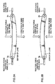
- FIGS. 3A and 3B are schematic diagrams showing loads exerted on a lower arm 3 according to a conventional design concept and on the lower arm 3 according to the technological concept of the present embodiment, respectively.
- a side force exerted on the wheel acts on the lower arm 3 via the wheel support member 2 during a cornering maneuver of the motor vehicle, for instance.
- the vehicle body member 1 exerts a reaction force on the lower arm 3 so that the lower arm 3 receives a compressive force acting along a longitudinal direction.
- a center of load exerted on the lower arm 3 is represented by an imaginary line interconnecting axes of the shaft 3a and the shaft 3b which serve as pivot axes as illustrated.
- the lower arm 3 receives a compressive force exerted by the coil spring 6 which acts to restore an original length from a compressed state.
- a middle portion of the lower arm 3 receives a downward-oriented reaction force exerted by the coil spring 6.
- part of the lower arm is recessed to form a dish-shaped coil spring seat portion.
- the direction of bend of the lower arm 3 due to the compressive force produced by the side force exerted from the wheel and the reaction force exerted from the vehicle body member 1 is downward as is the direction of the reaction force exerted by the coil spring 6 as shown in FIG. 3A . Therefore, the lower arm 3 receives superimposed loads which cause the lower arm 3 to bend downward, making it essential for the lower arm 3 to have high stiffness.
- a lower arm structure shown in FIG. 3B does not require so high a degree of stiffness of the lower arm 3 as the lower arm structure of FIG. 3A . Consequently, the lower arm structure of the embodiment shown in FIG. 3B makes it possible to reduce the weight of the lower arm 3 as well as the modulus of elasticity of the coil spring 6, yet ensuring an increased level of ride quality.
- the center of stiffness of the lower arm 3 and, in particular, the center of stiffness of a portion of the lower arm 3 receiving the reaction force from the coil spring 6, should be located above the aforementioned center of load exerted on the lower arm 3. If the lower arm 3 can be structured with the center of stiffness thus located, the bending force exerted on the lower arm 3 due to the compressive force applied thereto and the bending force exerted on the lower arm 3 due to the reaction force from the coil spring 6 cancel each other out. As a result, the weight of the lower arm 3 can be reduced while providing sufficient durability against the side force and the modulus of elasticity of the coil spring 6 can be reduced, yet ensuring a high level of ride quality.
- the center of stiffness of the lower arm 3 is located higher in the present embodiment.
- One approach to locating the center of stiffness of the lower arm 3 at a higher position is to increase the stiffness of an upper side of the lower arm 3.
- the present embodiment adopts a structure in which the location of the center of stiffness of the lower arm 3 is made higher by increasing the stiffness of the upper side of the lower arm 3 mainly with many constituent parts disposed on top of the lower arm 3..
- the center of stiffness of a lower arm can be obtained by the following steps of calculations:
- FIG. 4A is a perspective view showing the external appearance of the lower arm 3
- FIG. 4B is a side view of the lower arm 3
- FIG. 4C is a bottom view of the lower arm 3.
- the lower arm 3 includes an arm unit 31 fitted with the shaft 3a at one end and the shaft 3b at the other end, and a seat member 32 constituting a coil spring seat portion for supporting the coil spring 6.
- the seat member 32 is formed as a separate element and assembled with the arm unit 31.
- the seat member 32 is attached to a top surface of the arm unit 31 so that the seat member 32 is located, almost in its entirety, above the top surface of the arm unit 31.
- the seat member 32 Having a supporting surface 321 which forms a seat on which a lower end of the coil spring 6 rests, the seat member 32 is structured such that the supporting surface 321 is level with or located above the top surface of the arm unit 31.
- an upper part of the lower arm 3 where the coil spring seat portion receiving the reaction force from the coil spring 6 is located is given a high degree of stiffness and the center of stiffness of the lower arm 3 becomes higher than that of the aforementioned conventional dish-shaped coil spring seat structure.
- the seat member 32 has a hollow protruding part 322 extending upward from the supporting surface 321 into an internal space of the coil spring 6 as depicted in FIG. 1 , the supporting surface 321 surrounding the protruding part 322 generally in an annular shape.
- the provision of this protruding part 322 serves to increase the stiffness of the upper part of the lower arm 3 at the coil spring seat portion and make the center of stiffness of the lower arm 3 higher.
- a circular protruding rim 322a slightly rising upward from a central portion 322b of the upper end surface of the protruding part 322.
- the central portion 322b of the upper end surface of the protruding part 322 is not flat but has a concave shape, curved like an inner surface of a sphere sloping downward from the outer periphery (protruding rim 322a) toward the center.
- This structure serves to increase the stiffness of the protruding part 322. Consequently, the stiffness of the upper part of the lower arm 3 is further increased at the coil spring seat portion and the center of stiffness of the lower arm 3 is made still higher.
- the arm unit 31 includes a main arm member 311 which is curved slightly downward and a bracket member 312 disposed on top of the main arm member 311 for adjusting the vertical position of the seat member 32 which is attached to a top surface of the bracket member 312.
- the main arm member 311 has a generally U-shaped cross section opening upward while the bracket member 312 has a generally U-shaped cross section opening downward.
- the main arm member 311 and the bracket member 312 both having the generally U-shaped cross section serve to reduce the weight of the lower arm 3.
- the main arm member 311 is curved downward, it is possible to increase the total length of the coil spring 6.
- the vertical position of the seat member 32 can be adjusted due to the provision of the bracket member 312, it is possible to minimize a lowering of the center of stiffness of the lower arm 3.
- a central portion 311 a of a bottom surface of the arm unit 31 (that is, a bottom surface of the main arm member 311) located below the seat member 32 protrudes upward from a surrounding portion 311 b (refer to FIG. 4C ). As the central portion 311 a of the arm unit 31 bulges upward in this way, the center of stiffness of the lower arm 3 is made yet higher.
- the seat member 32 is attached to the bracket member 312 at an edge 32a on an inner side facing the vehicle body member 1 and at an edge 32b on an outer side facing the wheel support member 2. Since the seat member 32 is attached to the bracket member 312 at two points (32a, 32b) separated from each other along the longitudinal direction of the lower arm 3, the seat member 32 can effectively resist the bending force exerted on the lower arm 3.
- the location of the seat member 32 on the lower arm 3 is offset toward the side of the wheel support member 2 along the longitudinal direction of the lower arm 3 (refer to FIG. 4B ).
- the protruding part 322 of the seat member 32 is formed such that the protruding part 322 has a larger height on the inner side near the middle of the lower arm 3 than at the outer side facing the wheel support member 2 (refer to FIG. 4B ).
- the seat member 32 is offset from the middle of the lower arm 3 along the longitudinal direction thereof as mentioned above, so that it is desirable to enhance the stiffness of the middle portion of the lower arm 3 where the greatest bending force is applied. Since the protruding part 322 of the seat member 32 is made higher on the inner side near the middle of the lower arm 3 in this structure, it is possible to locate the center of stiffness of the lower arm 3 at a higher position at the middle portion of the lower arm 3.
- the seat member 32 further has a stopper portion 323 protruding upward from the supporting surface 321 of the seat member 32 for prohibiting the coil spring 6 from rotating about its own central (longitudinal) axis.
- the stopper portion 323 is a hollow structure bulging sideways from a cylindrical side surface of the protruding part 322 of the seat member 32.
- the stopper portion 323 is formed along the longitudinal direction of the lower arm 3 on the supporting surface 321 at a portion thereof closer to the vehicle body member 1. Since the seat member 32 is offset from the middle of the lower arm 3 along the longitudinal direction thereof as mentioned above, it is desirable to enhance the stiffness of the middle portion of the lower arm 3 where the greatest bending force is applied.
- the stopper portion 323 is formed along the longitudinal direction of the lower arm 3 on the supporting surface 321 at the portion thereof closer to the vehicle body member 1 (that is, close to the middle of the lower arm 3), so that the stopper portion 323 can serve as an element resisting the bending force applied to the middle portion of the lower arm 3.
- the seat member 32 further has a pair of facing flange portions 324 extending downward from the supporting surface 321, the flange portions 324 forming side surfaces of the seat member 32.
- the seat member 32 may be structured in such a way that the flange portions 324 extend upward from the supporting surface 321. Since the seat member 32 has the protruding part 322, however; this alternative structure would give the seat member 32 an extraordinarily high stiffness, causing the seat member 32 to exhibit a bending characteristic significantly differing from that of the arm unit 31 and leading to eventual separation of the arm unit 31 and the seat member 32, for instance. Under these circumstances, the seat member 32 is structured such that the flange portions 324 extend downward from the supporting surface 321 to give the seat member 32 an appropriate level of stiffness in the present embodiment.
- the flange portions 324 do not form a perfectly annular shape but has cutouts 324a located one each on the inner side facing the vehicle body member 1 and on the outer side facing the wheel support member 2 to allow the arm unit 31 to pass through.
- the provision of these cutouts 324a serves to facilitate the mounting of the seat member 32 on the arm unit 31 and prevents the seat member 32 from exhibiting a bending characteristic significantly differing from that of the arm unit 31, because the seat member 32 having the cutouts 324a has lower stiffness than a seat member 32 of which flange portion 324 forms an unbroken annular shape.
- FIG. 5A is a side view showing the center of load exerted on the lower arm 3 of the embodiment
- FIG. 5B is a cross-sectional view taken along lines X-X of FIG. 5A
- FIG. 5C is a cross-sectional view of a coil spring seat portion according to the aforementioned conventional lower arm structure showing the relationship between the location of the center of load and the location of the center of stiffness.
- the center of load exerted on the lower arm 3 is represented by an imaginary line interconnecting the axes of the shaft 3a and the shaft 3b which serve as the pivot axes.
- the center of stiffness of the lower arm 3 is located above the center of load exerted on the lower arm 3. Since the center of stiffness is located above the center of load in the lower arm 3 of the embodiment, the lower arm 3 bends upward when a compressive force acts on the lower arm 3 along the longitudinal direction thereof.
- the bending force exerted on the lower arm 3 due to the compressive force applied thereto and the bending force exerted on the lower arm 3 due to the reaction force from the coil spring 6 cancel each other out.
- the weight of the lower arm 3 can be reduced while providing sufficient durability against the side force and the modulus of elasticity of the coil spring 6 can be reduced, yet ensuring a high level of ride quality.
- the center of stiffness of the lower arm is markedly offset downward from the center of load exerted on the lower arm and, thus, the lower arm bends downward when a compressive force acts thereon as previously mentioned. Therefore, the conventional lower arm structure does not produce the same working and effects as the aforementioned structure of the present embodiment.
- the location (height) of the center of stiffness is so determined that the upward bending force exerted on the lower arm 3 due to the compressive force produced by the side force exerted from the wheel and the reaction force exerted from the vehicle body member 1 is approximately equal to the downward bending force exerted on the lower arm 3 due to the reaction force from the coil spring 6 when the side force exerted on the lower arm 3 is maximized, the upward bending force and the downward bending force exerted on the lower arm 3 cancel each other out almost completely. If the lower arm 3 is so structured, it is possible to further reduce the weight of the lower arm 3 as well as the modulus of elasticity of the coil spring 6.
- the center of stiffness of the lower arm 3 be positioned at the same height as or above the center of load exerted on the lower arm 3 not only in the area where the central axis of the coil spring 6 passes but in every area of the lower arm 3 located beneath the coil spring 6.
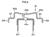
- the embodiment may be modified such that the lower arm 3 employs a main arm member 311' having a generally U-shaped cross section opening downward as shown in FIG. 6 .
- This variation of the embodiment serves to locate the center of stiffness of the lower arm 3 at a higher position than in the lower arm 3 employing the upward-opening main arm member 311.
- a suspension system of the invention includes a lower arm having an I-shaped cross section disposed between a vehicle body and a wheel support member, and a coil spring which is placed between the vehicle body and a coil spring seat portion of the lower arm in a manner that the coil spring can be compressed along a vertical direction, wherein an inner end (one end) of the lower arm is attached to the vehicle body in such a way that the lower arm can swing up and down with respect to the vehicle body, while an outer end (the other) of the lower arm is attached to the wheel support member in such a way that the lower arm can swing up and down with respect to the wheel support member.
- a center of stiffness of the lower arm is located above with respect to a line, or a centerline of load applied to the lower arm, interconnecting a pivot axis of the lower arm at the inner end thereof and a pivot axis of the lower arm at the outer end thereof in such a way that the lower arm bends upward when a compressive force is applied thereto from the vehicle body and the wheel support member.
- the "center of stiffness" of any mechanical component refers to a point where that component exhibits maximum stiffness and the location of the center of stiffness of the component is determined by various factors, such as material, overall shape and cross-sectional shape of the component and how that component has been formed.
- the lower arm is not required to have so high a degree of stiffness and this makes it possible to reduce the weight of the lower arm. Also, the aforementioned structure of the suspension system makes it possible to reduce the modulus of elasticity of the coil spring and achieve an increased level of ride quality.
- the location of the center of stiffness of the lower arm is preferably so determined that an upward bending force exerted on the lower arm due to a side force exerted on a wheel becomes approximately equal to a downward bending force exerted on the lower arm due to a reaction force from the coil spring when the side force is maximized.
- the aforementioned coil spring seat portion preferably includes a supporting surface for supporting the coil spring and a protruding part extending upward from the supporting surface into an internal space of the coil spring, the supporting surface surrounding the protruding part generally in an annular shape.
- this protruding part serves to increase the stiffness of an upper part of the lower arm at the coil spring seat portion and make the center of stiffness of the lower arm higher.
- the protruding part becomes structurally more rigid.
- the stiffness of the upper part of the lower arm is more increased at the coil spring seat portion and the center of stiffness of the lower arm is made even higher.
- the upper end surface of the protruding part of the coil spring seat portion preferably has a concave shape, curved like an inner surface of a sphere sloping downward from an outer periphery toward a central portion of the upper end surface of the protruding part.
- the upper end surface of the protruding part of the coil spring seat portion is formed into a concave shape, so that the stiffness of the protruding part is increased. Consequently, the stiffness of the upper part of the lower arm is further increased at the coil spring seat portion and the center of stiffness of the lower arm is made still higher.
- the protruding part of the coil spring seat portion is preferably made higher on an inner side along a longitudinal direction of the lower arm near a mid-length point thereof.
- the protruding part of the coil spring seat portion is made higher on the inner side near the middle of the lower arm where the greatest bending force is applied and, therefore, it is possible to locate the center of stiffness of the lower arm at a higher position at a middle portion of the lower arm.
- the lower arm includes an arm unit of which both ends constitute the aforementioned inner end and outer end of the lower arm, and a seat member including a supporting surface for supporting the coil spring and the coil spring seat portion, the seat member being an element formed separately from the arm unit, wherein the arm unit includes a main arm member which is curved downward and a bracket member disposed on top of the main arm member for adjusting the vertical position of the seat member, and wherein the seat member is attached to a top surface of the bracket member.
- the main arm member is curved downward in this structure, it is possible to increase the total length of the coil spring. Also, since the seat member is attached to the top surface of the bracket member, it is possible to locate the center of stiffness of the lower arm at a higher position. Additionally, since the vertical position of the seat member can be adjusted due to the provision of the bracket member, it is possible to minimize a lowering of the center of stiffness of the lower arm even when the main arm member is bent downward.
- the main arm member has a generally U-shaped cross section opening downward.
- the main arm member has a generally U-shaped cross section opening downward in this structure, it is possible to locate the center of stiffness of the lower arm at a higher position.
- the seat member is preferably attached to the bracket member at an end facing the vehicle body and at another end facing the wheel support member.
- the seat member is attached to the bracket member at two points separated from each other along the longitudinal direction of the lower arm, so that the seat member can effectively resist the bending force exerted on the lower arm.
- the lower arm includes an arm unit of which both ends constitute the inner end and the outer end of the lower arm, and a seat member including a supporting surface for supporting the coil spring and the coil spring seat portion, the seat member being an element formed separately from the arm unit, wherein the seat member is located at a position offset toward the wheel support member along a longitudinal direction of the lower arm, the seat member having a stopper portion protruding upward from the supporting surface of the seat member for prohibiting the coil spring from rotating about a longitudinal axis thereof, and wherein the stopper portion is formed along the longitudinal direction of the lower arm on the supporting surface at a portion thereof closer to the vehicle body.
- the stopper portion is formed along the longitudinal direction of the lower arm on the supporting surface at the portion thereof closer to the vehicle body, so that the stopper portion can serve as an element resisting the bending force applied to the middle portion of the lower arm.
- a central portion of a bottom surface of the lower arm located below the coil spring seat portion preferably protrudes upward from a surrounding portion.
- the lower arm includes an arm unit of which both ends constitute the inner end and the outer end of the lower arm, and a seat member including the supporting surface for supporting the coil spring and the coil spring seat portion, the seat member being an element formed separately from the arm unit, wherein the seat member has a flange extending downward from the supporting surface of the seat member, the flange forming a side surface of the seat member.
- the flange extends downward from the supporting surface of the seat member.
- the seat member may be structured in such a way that the flange extends upward from the supporting surface of the seat member. Since the seat member has the aforementioned protruding part, however, this alternative structure would give the seat member an extraordinarily high stiffness, causing the seat member to exhibit a bending characteristic significantly differing from that of the arm unit and leading to eventual separation of the arm unit and the seat member, for instance. Under these circumstances, the seat member is structured such that the flange extends downward from the supporting surface of the seat member in this invention to give the seat member an appropriate level of stiffness.
- the flange may have a cutout to allow the arm unit to pass through.
- the provision of the cutout formed in the flange serves to facilitate the mounting of the seat member on the arm unit and prevents the seat member from exhibiting a bending characteristic significantly differing from that of the arm unit, because the seat member having the cutout has lower stiffness than a seat member of which flange forms an unbroken annular shape.
- Another suspension system of the invention includes a lower arm having an I-shaped cross section disposed between a vehicle body and a wheel support member, and a coil spring which is placed between the vehicle body and a coil spring seat portion of the lower arm in a manner that the coil spring can be compressed along a vertical direction, wherein an inner end of the lower arm is attached to the vehicle body in such a way that the lower arm can swing up and down with respect to the vehicle body, while an outer end of the lower arm is attached to the wheel support member in such a way that the lower arm can swing up and down with respect to the wheel support member.
- the lower arm includes an arm unit of which both ends constitute the aforementioned inner end and outer end of the lower arm, and a seat member including a supporting surface for supporting the coil spring and the coil spring seat portion, the seat member being an element formed separately from the arm unit, wherein the seat member has a protruding part extending upward from the supporting surface into an internal space of the coil spring, and wherein the seat member is attached to a top surface of the arm unit so that the seat member is located almost in an entirety thereof above the top surface of the arm unit.
- the seat member is located almost in its entirety above the top surface of the arm unit and has the protruding part extending upward from the supporting surface. Therefore, an upper part of the lower arm, where the coil spring seat portion receiving a reaction force from the coil spring is located, is given a high degree of stiffness and the center of stiffness of the lower arm becomes considerably higher than that of the earlier-mentioned conventional dish-shaped coil spring seat structure.
Landscapes
- Engineering & Computer Science (AREA)
- Mechanical Engineering (AREA)
- Vehicle Body Suspensions (AREA)
- Springs (AREA)
- Vibration Prevention Devices (AREA)
Claims (12)
- Aufhängungssystem, umfassend:einen unteren Arm (3) mit 1-förmigen Querschnitt, der zwischen einem Fahrzeugkörper (1) und einem Radhalter- bzw. -stützglied (2) angeordnet ist, undeine Schraubenfeder (6), die zwischen dem Fahrzeugkörper (1) und einem Schraubenfeder-Sitzabschnitt (32) des unteren Arms (3) auf eine Art plaziert ist, dass die Schraubenfeder entlang einer vertikalen Richtung zusammengedrückt wird;wobei ein Ende (3a) des unteren Arms (3) an dem Fahrzeugkörper auf solch eine Weise angebracht ist, dass der untere Arm (3) bezüglich des Fahrzeugkörpers nach oben und unten schwenken kann, während das andere Ende (3b) des unteren Arms (3) an dem Radhalterglied auf solch eine Weise angebracht ist, dass der unter Arm (3) bezüglich des Radhalterglieds (2) nach oben und unten schwenken kann;
dadurch gekennzeichnet, dass
sich ein Steifigkeitszentrum des unteren Arms (3) oberhalb bezüglich einer Linie befindet, die eine Schwenkachse des unteren Arms an dem einen Ende davon mit einer Schwenkachse des unteren Arms an dem anderen Ende davon auf solche eine Weise miteinander verbindet, dass sich der untere Arm nach oben biegt, wenn von dem Fahrzeugkörper (1) und dem Radhalterglied (2) eine Druckkraft an den unteren Arm (3) durch eine Seitenkraft angelegt wird, die auf ein Rad während einer Kurvenfahrt ausgeübt wird. - Aufhängungssystem nach Anspruch 1, wobei der Schraubenfeder-Sitzabschnitt (32) ein Sitzglied (32) mit einer tragenden bzw. stützenden Oberfläche bzw. Fläche (321) zum Tragen bzw. Stützten der Schraubenfeder und einen vorstehenden Teil (322) enthält, der sich von der tragenden bzw. stützenden Oberfläche bzw. Fläche (321) nach oben in einen Innenraum der Schraubenfeder (6) erstreckt, wobei die tragende bzw. stützende Oberfläche bzw. Fläche (321) den vorstehenden Teil (322) im Allgemeinen in einer Ringform umgibt.
- Aufhängungssystem nach Anspruch 2, wobei ein kreisförmiger, vorstehender Rand (322a) an einer oberen Endfläche bzw. -oberfläche des vorstehenden Teils (322) des Sitzglieds (32) gebildet ist.
- Aufhängungssystem nach Anspruch 2 oder 3, wobei eine obere Endfläche bzw. -oberfläche des vorstehenden Teils (322) des Sitzglieds (32) eine konkave Form aufweist, bei der eine Oberfläche bzw. Fläche von einem Außenumfang zu einem zentralen Abschnitt der oberen Endfläche bzw. -oberfläche des vorstehenden Teils (322) hin abfällt.
- Aufhängungssystem nach einem der Ansprüche 2 bis 4, wobei der vorstehende Teil (322) des Sitzglieds (32) an einer Innenseite entlang einer Längsrichtung des unteren Arms (3) nahe einem Mittellängenpunkt davon höher ist.
- Aufhängungssystem nach Anspruch 1, wobei der untere Arm (3) ferner ein Sitzglied (32) einschließlich einer tragenden bzw. stützenden Oberfläche bzw. Fläche (321) zum Tragen bzw. Stützen der Schraubenfeder (6) enthält, das Sitzglied (32) ein Element ist, das separat von dem unteren Armglied (311) gebildet ist;
wobei der untere Arm (3) ferner ein Klammer- bzw. Halterglied (312) enthält, das auf dem Armglied (311) angeordnet ist, um die vertikale Position des Sitzglieds (32) einzustellen bzw. anzupassen; und
wobei das Sitzglied (32) an einer oberen Oberfläche bzw. Fläche des Klammerglieds (312) angebracht ist. - Aufhängungssystem nach Anspruch 6, wobei das Armglied (311) einen sich nach unten hin öffnenden, im Allgemeinen U-förmigen Querschnitt aufweist.
- Aufhängungssystem nach Anspruch 6, wobei das Sitzglied (32) an dem Klammerglied (312) an einem dem Fahrzeugkörper (1) zugewandten Ende und an einem weiteren, dem Radhalterglied (2) zugewandten Ende angebracht ist.
- Aufhängungssystem nach Anspruch 1, wobei der untere Arm (3) ferner ein Sitzglied (32) einschließlich einer tragenden bzw. stützenden Oberfläche bzw. Fläche (321) zum Tragen bzw. Stützen der Schraubenfeder enthält, das Sitzglied (32) ein Element ist, das separat von dem unteren Armglied (311) gebildet ist;
wobei das Sitzglied (32) an einer Position angeordnet ist, die zu dem Radhalterglied (2) entlang einer Längsrichtung des unteren Armglieds (311) versetzt ist, und einen Stopperabschnitt (323) aufweist, der von der tragenden bzw. stützenden Oberfläche bzw. Fläche (321) nach oben ragt, um die Schraubenfeder (6) daran zu hindern, sich um eine Längsachse davon zu drehen; und
wobei der Stopperabschnitt (323) entlang der Längsrichtung des unteren Armglieds (311) an der tragenden bzw. stützenden Oberfläche bzw. Fläche (321) an einem Abschnitt davon näher an dem Fahrzeugkörper (1) gebildet ist. - Aufhängungssystem nach einem der Ansprüche 1 bis 8, wobei ein zentraler Abschnitt einer unteren Oberfläche bzw. Fläche des unteren Armglieds (311), der bzw. das unterhalb des Schraubenfeder-Sitzabschnitts (32) angeordnet ist, von einem umgebenden Abschnitt nach oben ragt.
- Aufhängungssystem nach einem der Ansprüche 2 bis 5, wobei das Sitzglied (32) ein Element ist, das separat von der Armeinheit (31) gebildet ist; und
wobei das Sitzglied (32) einen Flansch (324) aufweist, der sich von der tragenden bzw. stützenden Oberfläche bzw. Fläche (321) nach unten erstreckt, wobei der Flansch (324) eine Seitenfläche bzw. -oberfläche des Sitzglieds (32) darstellt. - Aufhängungssystem nach Anspruch 11, wobei der Flansch einen Ausschnitt (324a) aufweist, um dem unteren Armglied (311) zu erlauben, durch diesen zu treten bzw. zu verlaufen.
Applications Claiming Priority (2)
| Application Number | Priority Date | Filing Date | Title |
|---|---|---|---|
| JP2004043316A JP4360227B2 (ja) | 2004-02-19 | 2004-02-19 | サスペンション装置 |
| JP2004043316 | 2004-02-19 |
Publications (2)
| Publication Number | Publication Date |
|---|---|
| EP1566293A1 EP1566293A1 (de) | 2005-08-24 |
| EP1566293B1 true EP1566293B1 (de) | 2010-01-13 |
Family
ID=34709125
Family Applications (1)
| Application Number | Title | Priority Date | Filing Date |
|---|---|---|---|
| EP05002367A Ceased EP1566293B1 (de) | 2004-02-19 | 2005-02-04 | Aufhängungssystem |
Country Status (5)
| Country | Link |
|---|---|
| US (1) | US7387307B2 (de) |
| EP (1) | EP1566293B1 (de) |
| JP (1) | JP4360227B2 (de) |
| CN (1) | CN100431860C (de) |
| DE (1) | DE602005018848D1 (de) |
Families Citing this family (40)
| Publication number | Priority date | Publication date | Assignee | Title |
|---|---|---|---|---|
| AU2004236571B2 (en) * | 2003-12-06 | 2011-06-16 | Hyundai Motor Company | Multi-link rear suspension system |
| JP4360227B2 (ja) * | 2004-02-19 | 2009-11-11 | マツダ株式会社 | サスペンション装置 |
| US7980576B2 (en) * | 2005-08-17 | 2011-07-19 | Honda Motor Co., Ltd. | Vehicular suspension arm |
| FR2892166B1 (fr) * | 2005-10-13 | 2010-08-13 | Renault Sas | Gaine pour ressort de suspension |
| US7661689B2 (en) * | 2006-01-20 | 2010-02-16 | Yamaha Hatsudoki Kabushiki Kaisha | All terrain vehicle |
| US7959168B2 (en) * | 2006-04-04 | 2011-06-14 | Magna International Inc. | Suspension link with integral pivot assembly |
| JP4692578B2 (ja) * | 2008-05-30 | 2011-06-01 | トヨタ自動車株式会社 | 車両のサスペンションアーム |
| JP5049235B2 (ja) * | 2008-09-09 | 2012-10-17 | 本田技研工業株式会社 | 車両のサスペンションアーム |
| US8690176B2 (en) * | 2009-03-20 | 2014-04-08 | Magna International Inc. | Suspension arm/link for motor vehicle and method for making same |
| JP5293340B2 (ja) * | 2009-03-30 | 2013-09-18 | スズキ株式会社 | スプリングシート及びスプリングシートの取り付け構造 |
| JP5621208B2 (ja) * | 2009-04-09 | 2014-11-12 | スズキ株式会社 | サスペンションアーム |
| KR100987943B1 (ko) * | 2009-12-08 | 2010-10-29 | 쌍용자동차 주식회사 | 차량 경량화를 위한 i 빔 형상의 스프링 링크 |
| JP5246297B2 (ja) * | 2011-05-16 | 2013-07-24 | 日産自動車株式会社 | サスペンション組み付け構造、スプリングシート、サスペンション組み付け方法 |
| JP5293770B2 (ja) * | 2011-05-16 | 2013-09-18 | 日産自動車株式会社 | サスペンション構造、サスペンションリンク配置方法 |
| JP2013001180A (ja) * | 2011-06-14 | 2013-01-07 | Toyota Motor Corp | 車両用懸架装置 |
| JPWO2013124972A1 (ja) * | 2012-02-21 | 2015-05-21 | 株式会社ヨロズ | 車両用のサスペンションアーム |
| CN104114384A (zh) * | 2012-02-21 | 2014-10-22 | 株式会社万 | 车辆用悬挂臂 |
| JP5653969B2 (ja) * | 2012-06-26 | 2015-01-14 | 本田技研工業株式会社 | サスペンション装置 |
| JP6105338B2 (ja) * | 2013-03-14 | 2017-03-29 | ダイキョーニシカワ株式会社 | インストルメントパネル |
| DE102013205686A1 (de) * | 2013-03-28 | 2014-10-02 | Ford Global Technologies, Llc | Verbundlenkerachse für Fahrzeuge |
| DE102013006253A1 (de) * | 2013-04-11 | 2014-10-16 | Audi Ag | Verfahren zur Herstellung einer Luftleiteinrichtung für einen Fahrwerkslenker und Fahrwerkslenker mit einer Luftleiteinrichtung |
| DE102014118518B4 (de) * | 2014-12-12 | 2022-03-24 | Benteler Automobiltechnik Gmbh | Mehrteiliger Federlenker |
| US9610820B1 (en) * | 2015-10-28 | 2017-04-04 | Fca Us Llc | Vehicle suspension with jounce bumper and striker |
| DE102016100666B4 (de) * | 2016-01-15 | 2026-08-06 | Benteler Automobiltechnik Gmbh | Federlenker aus Stahl |
| JP2018052214A (ja) * | 2016-09-27 | 2018-04-05 | 本田技研工業株式会社 | サスペンションアームの補強構造及び製造方法 |
| CN106427442B (zh) * | 2016-09-29 | 2019-03-01 | 北京汽车股份有限公司 | 后下控制臂及具有其的车辆 |
| DE102017218682B4 (de) * | 2017-10-19 | 2021-05-06 | Ford Global Technologies, Llc | Längsblattfedervorrichtung mit Anschlagpuffer-Einheit |
| DE102018218082A1 (de) * | 2018-10-23 | 2020-04-23 | Volkswagen Aktiengesellschaft | Federlenker in Blechkonstruktion |
| EP3904131B1 (de) * | 2018-12-26 | 2023-08-16 | Nippon Steel Corporation | Bauteil einer kraftfahrzeugaufhängung |
| DE102019108548B4 (de) * | 2019-04-02 | 2023-12-28 | Benteler Automobiltechnik Gmbh | Federlenker |
| EP3722121B1 (de) * | 2019-04-11 | 2021-11-24 | Autotech Engineering Deutschland GmbH | Einschaliger federlenker |
| CA3136964A1 (en) | 2019-04-30 | 2020-11-05 | Polaris Industries Inc. | Vehicle with removable final drive |
| US12415394B2 (en) * | 2019-04-30 | 2025-09-16 | Polaris Industries, Inc. | Vehicle |
| JP7336257B2 (ja) * | 2019-05-13 | 2023-08-31 | 日立Astemo株式会社 | ロアアーム |
| US12187127B2 (en) | 2020-05-15 | 2025-01-07 | Polaris Industries Inc. | Off-road vehicle |
| DE102020212778B4 (de) * | 2020-10-09 | 2025-09-25 | Zf Friedrichshafen Ag | Fahrwerkbauteil mit mindestens einem Verbindungsabschnitt zum Verbinden mit einem Befestigungsabschnitt eines Fahrwerkelements |
| WO2022120802A1 (zh) * | 2020-12-11 | 2022-06-16 | 武汉路特斯汽车有限公司 | 一种弹簧臂及车辆 |
| KR102929653B1 (ko) * | 2021-03-11 | 2026-02-20 | 현대자동차주식회사 | 차량용 현가장치 |
| JP7825223B2 (ja) * | 2022-08-30 | 2026-03-06 | スズキ株式会社 | スプリングシート及びそれを備えるサスペンション |
| USD1135764S1 (en) | 2024-06-25 | 2026-07-21 | Polaris Industries Inc. | Dashboard for an off-road vehicle |
Family Cites Families (27)
| Publication number | Priority date | Publication date | Assignee | Title |
|---|---|---|---|---|
| US1595317A (en) * | 1924-07-24 | 1926-08-10 | Cook Spring Company | Spring and seat therefor |
| US2162828A (en) * | 1937-05-05 | 1939-06-20 | Chrysler Corp | Wheel suspension |
| US2455343A (en) * | 1945-04-11 | 1948-11-30 | Chrysler Corp | Joint |
| US2483185A (en) * | 1945-09-18 | 1949-09-27 | George W Crabtree | Frictional spring control means and their mounting on vehicles |
| US2466094A (en) * | 1946-03-23 | 1949-04-05 | Frost Railway Supply Co | Railway car spring |
| FR1030793A (fr) * | 1951-01-08 | 1953-06-17 | Materiels Hispano Suiza S A So | Perfectionnements apportés aux systèmes de suspension pour roues indépendantes, notamment à ceux pour roues indépendantes motrices et directrices |
| FR1063269A (fr) * | 1951-07-10 | 1954-04-30 | Daimler Benz Ag | Dispositif de suspension de demi-essieux oscillants, en particulier pour véhicules |
| US3049359A (en) * | 1960-05-09 | 1962-08-14 | Gen Motors Corp | Rear wheel suspension system for vehicles |
| US3069149A (en) * | 1960-05-31 | 1962-12-18 | Gen Motors Corp | Coil spring suspension with auxiliary overload bumper |
| GB1084157A (de) * | 1965-06-17 | |||
| US3727939A (en) * | 1971-06-23 | 1973-04-17 | Gen Motors Corp | Vehicle suspension control arm |
| US3781033A (en) * | 1972-11-08 | 1973-12-25 | Gen Motors Corp | Vehicle height adjusting suspension arrangement |
| US3940161A (en) * | 1974-12-23 | 1976-02-24 | Ford Motor Company | Independent wheel suspension for a motor vehicle |
| FR2379731A1 (fr) * | 1977-02-08 | 1978-09-01 | Snecma | Ressort lineaire |
| DE2942135C2 (de) * | 1979-10-18 | 1987-05-14 | Volkswagen AG, 3180 Wolfsburg | Unterlage aus gummielastischem Material für Schraubenfedern einer Kraftfahrzeug-Federung |
| DE3012873A1 (de) * | 1980-04-02 | 1981-10-08 | Daimler-Benz Ag, 7000 Stuttgart | Daempferbein-achse fuer personenkraftwagen |
| US4690428A (en) * | 1984-11-15 | 1987-09-01 | Ford Motor Company | Double isolated jounce bumper system |
| US4989894A (en) * | 1989-10-30 | 1991-02-05 | Chrysler Corporation | Independent rear suspension |
| CN2128914Y (zh) * | 1992-03-20 | 1993-03-31 | 四川都江机械厂 | 双横臂扭杆弹簧独立悬架前轴总成 |
| JP3737837B2 (ja) * | 1994-06-24 | 2006-01-25 | トヨタ自動車株式会社 | 車両用サスペンションアーム |
| JP3191654B2 (ja) * | 1995-08-30 | 2001-07-23 | トヨタ自動車株式会社 | サスペンションアーム |
| JP3741301B2 (ja) * | 1998-01-30 | 2006-02-01 | スズキ株式会社 | ラテラルロッド取付構造 |
| EP0963866A3 (de) * | 1998-06-08 | 2003-09-24 | Dr.Ing. h.c.F. Porsche Aktiengesellschaft | Radaufhängung für ein Kraftfahrzeug |
| DE10106915C2 (de) * | 2001-02-15 | 2003-02-13 | Benteler Automobiltechnik Gmbh | Federungsanordnung |
| JP2002293120A (ja) * | 2001-03-29 | 2002-10-09 | Mazda Motor Corp | 自動車のサスペンション構造 |
| JP4698873B2 (ja) | 2001-04-18 | 2011-06-08 | 株式会社エフテック | 車両用サスペンションアームの製造方法 |
| JP4360227B2 (ja) * | 2004-02-19 | 2009-11-11 | マツダ株式会社 | サスペンション装置 |
-
2004
- 2004-02-19 JP JP2004043316A patent/JP4360227B2/ja not_active Expired - Fee Related
-
2005
- 2005-02-03 CN CNB2005100094103A patent/CN100431860C/zh not_active Expired - Fee Related
- 2005-02-04 DE DE602005018848T patent/DE602005018848D1/de not_active Expired - Lifetime
- 2005-02-04 EP EP05002367A patent/EP1566293B1/de not_active Ceased
- 2005-02-11 US US11/055,081 patent/US7387307B2/en not_active Expired - Fee Related
Also Published As
| Publication number | Publication date |
|---|---|
| US20050184481A1 (en) | 2005-08-25 |
| CN1657331A (zh) | 2005-08-24 |
| US7387307B2 (en) | 2008-06-17 |
| JP2005231512A (ja) | 2005-09-02 |
| JP4360227B2 (ja) | 2009-11-11 |
| DE602005018848D1 (de) | 2010-03-04 |
| EP1566293A1 (de) | 2005-08-24 |
| CN100431860C (zh) | 2008-11-12 |
Similar Documents
| Publication | Publication Date | Title |
|---|---|---|
| US7387307B2 (en) | Suspension system | |
| EP0174007B1 (de) | Aufbau eines Kraftfahrzeugfederbeines mit verstellbaren Tragflächen | |
| AU2004236571B2 (en) | Multi-link rear suspension system | |
| EP0071250B1 (de) | Aufhängung vom Schwenkarm-Typ mit Seitenstange für ein Kraftfahrzeug | |
| US8511698B2 (en) | Suspension system for a vehicle | |
| EP2062754B1 (de) | Sitzmontagestruktur mit niedriger Feder für Fahrzeugaufhängung | |
| CN101445027B (zh) | 用于车辆悬架的下弹簧座安装结构 | |
| EP0721855B1 (de) | Radaufhängung für ein Fahrzeug | |
| JPH1016527A (ja) | 車両用サスペンション | |
| US9579946B2 (en) | Trailing arm bush for coupled torsion beam axle | |
| JP6934276B2 (ja) | サスペンションアーム及び車両の懸架装置 | |
| CN100457481C (zh) | 多联杆后悬架系统 | |
| CA1065351A (en) | Independent suspension system | |
| JP2008201307A (ja) | スタビライザ装置 | |
| KR101361246B1 (ko) | 자동차의 커플드 토션 빔 액슬 | |
| JP2008201306A (ja) | スタビライザ装置 | |
| JPH11208233A (ja) | 車両のサスペンション装置 | |
| US20240326535A1 (en) | Suspension device | |
| JP2855883B2 (ja) | サスペンション装置 | |
| JP7501955B2 (ja) | 弾性体ブッシュの支持構造 | |
| JP2727771B2 (ja) | リヤサスペンション | |
| JPS595609Y2 (ja) | 車輪懸架装置のためのア−ム組立体 | |
| JPH11291736A (ja) | スタビライザの支持構造 | |
| KR100428132B1 (ko) | 현가장치의 스트럿어셈블리 | |
| EP1445128B1 (de) | Aufhängungssystem |
Legal Events
| Date | Code | Title | Description |
|---|---|---|---|
| PUAI | Public reference made under article 153(3) epc to a published international application that has entered the european phase |
Free format text: ORIGINAL CODE: 0009012 |
|
| AK | Designated contracting states |
Kind code of ref document: A1 Designated state(s): AT BE BG CH CY CZ DE DK EE ES FI FR GB GR HU IE IS IT LI LT LU MC NL PL PT RO SE SI SK TR |
|
| AX | Request for extension of the european patent |
Extension state: AL BA HR LV MK YU |
|
| 17P | Request for examination filed |
Effective date: 20051224 |
|
| AKX | Designation fees paid |
Designated state(s): DE |
|
| 17Q | First examination report despatched |
Effective date: 20060221 |
|
| GRAP | Despatch of communication of intention to grant a patent |
Free format text: ORIGINAL CODE: EPIDOSNIGR1 |
|
| GRAS | Grant fee paid |
Free format text: ORIGINAL CODE: EPIDOSNIGR3 |
|
| GRAA | (expected) grant |
Free format text: ORIGINAL CODE: 0009210 |
|
| AK | Designated contracting states |
Kind code of ref document: B1 Designated state(s): DE |
|
| REF | Corresponds to: |
Ref document number: 602005018848 Country of ref document: DE Date of ref document: 20100304 Kind code of ref document: P |
|
| PLBE | No opposition filed within time limit |
Free format text: ORIGINAL CODE: 0009261 |
|
| STAA | Information on the status of an ep patent application or granted ep patent |
Free format text: STATUS: NO OPPOSITION FILED WITHIN TIME LIMIT |
|
| 26N | No opposition filed |
Effective date: 20101014 |
|
| PGFP | Annual fee paid to national office [announced via postgrant information from national office to epo] |
Ref country code: DE Payment date: 20190122 Year of fee payment: 15 |
|
| REG | Reference to a national code |
Ref country code: DE Ref legal event code: R119 Ref document number: 602005018848 Country of ref document: DE |
|
| PG25 | Lapsed in a contracting state [announced via postgrant information from national office to epo] |
Ref country code: DE Free format text: LAPSE BECAUSE OF NON-PAYMENT OF DUE FEES Effective date: 20200901 |