EP1564899A1 - Empfangsvorrichtung - Google Patents
Empfangsvorrichtung Download PDFInfo
- Publication number
- EP1564899A1 EP1564899A1 EP03715673A EP03715673A EP1564899A1 EP 1564899 A1 EP1564899 A1 EP 1564899A1 EP 03715673 A EP03715673 A EP 03715673A EP 03715673 A EP03715673 A EP 03715673A EP 1564899 A1 EP1564899 A1 EP 1564899A1
- Authority
- EP
- European Patent Office
- Prior art keywords
- beam former
- arrival
- calculator
- correlators
- receiving
- Prior art date
- Legal status (The legal status is an assumption and is not a legal conclusion. Google has not performed a legal analysis and makes no representation as to the accuracy of the status listed.)
- Withdrawn
Links
Images


Classifications
-
- H—ELECTRICITY
- H01—ELECTRIC ELEMENTS
- H01Q—ANTENNAS, i.e. RADIO AERIALS
- H01Q21/00—Antenna arrays or systems
- H01Q21/06—Arrays of individually energised antenna units similarly polarised and spaced apart
- H01Q21/08—Arrays of individually energised antenna units similarly polarised and spaced apart the units being spaced along or adjacent to a rectilinear path
-
- H—ELECTRICITY
- H04—ELECTRIC COMMUNICATION TECHNIQUE
- H04B—TRANSMISSION
- H04B1/00—Details of transmission systems, not covered by a single one of groups H04B3/00 - H04B13/00; Details of transmission systems not characterised by the medium used for transmission
- H04B1/69—Spread spectrum techniques
- H04B1/707—Spread spectrum techniques using direct sequence modulation
- H04B1/7097—Interference-related aspects
- H04B1/711—Interference-related aspects the interference being multi-path interference
- H04B1/7115—Constructive combining of multi-path signals, i.e. RAKE receivers
- H04B1/7117—Selection, re-selection, allocation or re-allocation of paths to fingers, e.g. timing offset control of allocated fingers
-
- H—ELECTRICITY
- H04—ELECTRIC COMMUNICATION TECHNIQUE
- H04B—TRANSMISSION
- H04B7/00—Radio transmission systems, i.e. using radiation field
- H04B7/02—Diversity systems; Multi-antenna system, i.e. transmission or reception using multiple antennas
- H04B7/04—Diversity systems; Multi-antenna system, i.e. transmission or reception using multiple antennas using two or more spaced independent antennas
- H04B7/08—Diversity systems; Multi-antenna system, i.e. transmission or reception using multiple antennas using two or more spaced independent antennas at the receiving station
- H04B7/0837—Diversity systems; Multi-antenna system, i.e. transmission or reception using multiple antennas using two or more spaced independent antennas at the receiving station using pre-detection combining
- H04B7/0842—Weighted combining
- H04B7/086—Weighted combining using weights depending on external parameters, e.g. direction of arrival [DOA], predetermined weights or beamforming
Definitions
- the present invention relates to path detection and direction-of-arrival estimation techniques for use in a receiving apparatus in wireless communication equipment that uses an array antenna.
- a technique called RAKE receiving that gathers the received signals from the multiple paths and combines them into one signal.
- a receiving apparatus that performs RAKE receiving is equipped with a searcher for determining path timing, i.e., the phase of the despreading code to be applied to each RAKE finger.
- the searcher performs correlation using a matched filter to correlate each received signal with a prescribed code, obtains a delay profile by adding up its output, and obtains the path timing by detecting a peak in the delay profile.
- the wireless communication equipment at the above base station is equipped with an array antenna so that the antenna directivity (the direction of the beam formed by a beam former) can be adaptively changed according to the direction of the mobile unit, the number of mobile units that can be served by the base station can be increased. In that case, as the transmit power of each mobile unit is controlled to an even lower level, it becomes necessary to further enhance the path detection accuracy of the searcher.
- Patent Document 1 describes that the correlation results obtained for a plurality of antennas forming an array antenna are converted into power values and a delay profile is generated by simply summing the power values. Patent Document 1 further describes that corrections between the respective antennas are computed from the plurality of correlation results and their sum is used as an initial value for a beam former in a receiver section so that the reception can be started by making the weight to be applied to the beam former to converge immediately after achieving synchronization by the searcher.
- Patent Document 1
- Patent Document 1 has the problem that there is a limit to the extent to which the path detection and the accuracy can be improved because the delay profile is obtained by simply combining the power values of the correlation results obtained from the plurality of radiowaves arriving with different phases.
- An object of the present invention is to enhance the accuracy of path detection in a receiving apparatus that employs an array antenna.
- a receiving apparatus comprising a receiving section for performing RAKE receiving with a plurality of fingers and a searcher for detecting path timing to be given to each of the fingers of the receiving section, each of the fingers of the receiving section comprising a first beam former for performing beam forming based on signals received from a plurality of antennas forming an array antenna
- the searcher comprises: a plurality of correlators, each for performing correlation processing on the signal received from each of the plurality of antennas; a direction-of-arrival calculator for estimating direction of arrival based on outputs of the plurality of correlators; a second beam former for performing beam forming on the outputs of the plurality of correlators in accordance with an estimation result supplied from the direction-of-arrival calculator; and a path detector for detecting the path timing based on an output of the second beam former.
- the estimation result from the direction-of-arrival calculator can be used in the first beam former.
- the estimation result from the direction-of-arrival calculator can also be used in a third beam former provided in a transmitting apparatus.
- the receiving apparatus further comprises a delay circuit which is placed after the plurality of correlators and before the second beam former.
- the receiving apparatus further comprises a first averager which is placed after the second beam former and before the path detector, and which averages the output of the second beam former with a first averaging time constant
- the direction-of-arrival estimator includes a calculator for performing calculations to estimate the direction of arrival by receiving the outputs of the plurality of correlators, and a second averager for averaging an output of the calculator with a second averaging time constant which is different from the first averaging time constant.
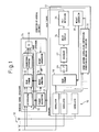
- Figure 1 shows the configuration of a receiver according to one embodiment of the present invention.
- a radio-frequency signal received by each antenna in an array antenna 10 is first converted by a frequency converter and a quadrature demodulator, not shown, into a baseband signal comprising I-phase and Q-phase components, and then sampled and quantized by an A/D converter, not shown, into a complex-valued digital baseband signal which is supplied to a searcher 12 for path timing detection and a received signal processor 14 for adaptive array reception.
- the searcher 12 of the present invention accepts at its inputs all the antenna signals supplied from the array antenna 10, and each received signal is correlated with a spreading code by a correlator 16 provided for each antenna.
- the correlated signal of each antenna is fed to a beam former 18 which forms a beam in the direction of arrival of the signal; then, by performing power conversion (20) and time averaging (22), a delay profile 24 is generated to perform path detection (26) achieving a beam forming gain.
- the weight to be applied to the beam former 18 in the searcher 12 is obtained by estimating the direction of arrival (DOA) using the correlated signal of each antenna (28) in the searcher 12 and by converting it into a weight (30).
- DOA direction of arrival
- Information of the path timing estimated by the searcher 12 is used for finger allocation 31 and despreading 32 in the array antenna received signal processor 14, while the DOA information can be used as DOA information in a weight updater 34 of a beam former 33 or as its initial value.
- the received signal processor 14 can initiate the receiving process immediately after synchronization is achieved by the searcher 12.
- the DOA information obtained by the searcher can also be used as DOA information for a beam former provided in a transmitting section not shown.
- FIG. 2 A specific configuration for implementing the processing performed in the searcher 12 described with reference to Figure 1 is illustrated in Figure 2 in block diagram form.
- the in-phase processing 16 in Figure 1 is implemented in a matched filter 40 and an in-phase adder 42 in Figure 2.
- the signals received by the respective antennas in the array antenna are each correlated with a spreading code in the matched filter 40 and are added in phase on a symbol-by-symbol basis in the in-phase adder 42.
- each antenna signal is used for beam forming (18).
- the signal after the beam forming is multiplied by a complex conjugate and thus converted into power, and then averaged over time to generate the power delay profile (44), and detection of an effective path is performed (26) based on a threshold value.
- the signals added in phase for the respective antennas can be used for DOA estimation by estimating the received phase difference between the respective antennas.
- a DOA estimator/calculator 45 whose details are shown in Figure 2
- a complex multiplication is performed between adjacent antennas (46) (here, a complex conjugate is used as the reference side as shown by *), all the outputs are complex-added as they are equally spaced apart (48), and the sum is averaged over time (50), thereby obtaining correlation between the antennas and thus estimating the DOA.
- the profile obtained by the time averaging and necessary for the DOA estimation is called the DOA profile.
- the DOA estimate is converted into a weight (30 in Figure 1) which is used as the weight for the beam forming for generating the delay profile. Further, in a DOA detector 52, by referring to the value of the DOA profile at the detected path timing, DOA information for each path can be obtained.
- Figure 3 shows another example of the processing performed in the searcher.
- the profile cannot be generated based on the beam forming until after the weight for the beam former is first set by performing the first DOA estimation. This does not present much of a problem when performing path searching on signals arriving in succession but, in the case of a signal arriving and completing in a short single burst, there can occur cases where when the weight is successfully estimated, the signal is already completed and the beam forming cannot be performed; in such cases, path detection or signal detection cannot be performed utilizing the effect of the array antenna.
- a delay circuit 60 is provided before the beam former 18 to delay the signal until the weight is obtained by estimating the DOA; this makes it possible to receive a short bursty signal while also making it possible to perform path detection by performing beam forming at all times.
- the averaging time for the delay profile in the profile generator 44 and the averaging time for the DOA estimation in the DOA profile generator 50 ( Figure 2) be made unequal to each other.
- the reason is that, if the delay profile averaging time and the DOA estimation averaging time are equal and become synchronized to each other, since the source of both profiles is the same signal which contains noise, beam forming is also performed for the noise, defeating the purpose of the beam forming that suppresses the noise.
- Figures 4a and 4b show the averaging time in the case of a moving average
- Figures 5a and 5b show the averaging time in the case of an exponential average.
- each figure shows the case where the DOA estimation averaging time is set longer than the delay profile averaging time, but conversely, the delay profile averaging time may be set longer.
- the searcher of the prevent invention can achieve highly accurate path searching and direction-of-arrival estimation
- the array antenna when the array antenna is applied to a CDMA mobile communication system, it becomes possible to suppress the degradation of the path searching characteristics as well as the increase in transmit power due to incompleteness of the formed beam.
- the system capacity can be increased, without causing degradation in characteristics, when applying the array antenna.
Landscapes
- Engineering & Computer Science (AREA)
- Computer Networks & Wireless Communication (AREA)
- Signal Processing (AREA)
- Radio Transmission System (AREA)
- Mobile Radio Communication Systems (AREA)
- Variable-Direction Aerials And Aerial Arrays (AREA)
Applications Claiming Priority (1)
| Application Number | Priority Date | Filing Date | Title |
|---|---|---|---|
| PCT/JP2003/004124 WO2004088867A1 (ja) | 2003-03-31 | 2003-03-31 | 受信装置 |
Publications (2)
| Publication Number | Publication Date |
|---|---|
| EP1564899A1 true EP1564899A1 (de) | 2005-08-17 |
| EP1564899A4 EP1564899A4 (de) | 2009-12-02 |
Family
ID=33105360
Family Applications (1)
| Application Number | Title | Priority Date | Filing Date |
|---|---|---|---|
| EP03715673A Withdrawn EP1564899A4 (de) | 2003-03-31 | 2003-03-31 | Empfangsvorrichtung |
Country Status (5)
| Country | Link |
|---|---|
| US (1) | US7505509B2 (de) |
| EP (1) | EP1564899A4 (de) |
| JP (1) | JP4148950B2 (de) |
| CN (1) | CN100444531C (de) |
| WO (1) | WO2004088867A1 (de) |
Cited By (1)
| Publication number | Priority date | Publication date | Assignee | Title |
|---|---|---|---|---|
| US12379443B2 (en) * | 2021-10-01 | 2025-08-05 | Industry-Academic Cooperation Foundation, Yonsei University | Apparatus and method for estimating angle of arrival based on ultra-wideband wireless communication |
Families Citing this family (13)
| Publication number | Priority date | Publication date | Assignee | Title |
|---|---|---|---|---|
| JP4148950B2 (ja) * | 2003-03-31 | 2008-09-10 | 富士通株式会社 | 受信装置 |
| US20050113141A1 (en) * | 2003-11-20 | 2005-05-26 | Telefonaktiebolaget Lm Ericsson (Publ) | Spatial joint searcher and channel estimators |
| CN101084633B (zh) * | 2004-12-17 | 2011-05-18 | 华为技术有限公司 | 多径搜索器、细化处理单元及进行波达方向估计的方法 |
| CN100401650C (zh) * | 2004-12-24 | 2008-07-09 | 中兴通讯股份有限公司 | 一种智能天线自适应波束形成及数据解调方法 |
| CN100388846C (zh) * | 2005-07-08 | 2008-05-14 | 中兴通讯股份有限公司 | 一种移动通信智能天线系统中的下行链路波束赋形方法 |
| CN101291165B (zh) * | 2007-04-17 | 2012-11-14 | 电信科学技术研究院 | 一种多天线系统的序列检测方法和装置 |
| US8340588B2 (en) * | 2009-09-18 | 2012-12-25 | Her Majesty The Queen In Right Of Canada As Represented By The Minister Of National Defence | Handheld synthetic antenna array |
| CA2693012C (en) * | 2009-09-18 | 2015-06-23 | Her Majesty The Queen In Right Of Canada As Represented By The Ministeof National Defence | Signal detection in fading environments |
| WO2015144233A1 (en) | 2014-03-27 | 2015-10-01 | Telefonaktiebolaget L M Ericsson (Publ) | A beam forming receiver |
| KR102207844B1 (ko) * | 2014-07-08 | 2021-01-26 | 한국전자통신연구원 | 적어도 하나의 안테나 배열에 입사하는 신호의 도착 방향을 추정하는 시스템, 방법, 그리고 컴퓨터 판독가능 매체 |
| CN106688194B (zh) * | 2014-12-31 | 2020-04-21 | 华为技术有限公司 | 一种阵列天线波束调整装置和方法 |
| JP6834284B2 (ja) * | 2016-09-20 | 2021-02-24 | カシオ計算機株式会社 | 方向推定装置、方向推定方法、及び、プログラム |
| US11616563B2 (en) * | 2020-04-06 | 2023-03-28 | Samsung Electronics Co., Ltd. | Systems and methods for updating beamforming codebooks for angle-of-arrival estimation using compressive sensing in wireless communications |
Family Cites Families (35)
| Publication number | Priority date | Publication date | Assignee | Title |
|---|---|---|---|---|
| JP2671595B2 (ja) * | 1990-10-25 | 1997-10-29 | 日本電気株式会社 | 復調装置 |
| JPH0974372A (ja) * | 1995-09-04 | 1997-03-18 | Matsushita Electric Ind Co Ltd | スペクトラム拡散無線伝送受信装置 |
| US6188736B1 (en) * | 1997-12-23 | 2001-02-13 | At&T Wireless Svcs. Inc. | Near-optimal low-complexity decoding of space-time codes for fixed wireless applications |
| JP3233088B2 (ja) * | 1998-01-22 | 2001-11-26 | 松下電器産業株式会社 | 指向性制御アンテナ装置 |
| JP3716398B2 (ja) * | 1998-03-05 | 2005-11-16 | 富士通株式会社 | アレーアンテナによる到来方向推定方法及び該方法を用いたds−cdma受信装置 |
| JPH11251959A (ja) * | 1998-03-05 | 1999-09-17 | Fujitsu Ltd | 干渉キャンセラ装置及び無線通信装置 |
| JPH11266180A (ja) * | 1998-03-18 | 1999-09-28 | Fujitsu Ltd | 無線基地局のアレーアンテナシステム |
| JP3406831B2 (ja) * | 1998-03-19 | 2003-05-19 | 富士通株式会社 | 無線基地局のアレーアンテナシステム |
| JP3465739B2 (ja) * | 1998-04-07 | 2003-11-10 | 日本電気株式会社 | Cdma適応アンテナ受信装置及び通信システム |
| JP2000013290A (ja) * | 1998-06-24 | 2000-01-14 | Matsushita Electric Ind Co Ltd | ダイバーシチ通信装置及び方法 |
| JP3028804B2 (ja) * | 1998-07-03 | 2000-04-04 | 日本電気株式会社 | Cdma受信方法及び受信回路 |
| JP3029030B2 (ja) * | 1998-08-05 | 2000-04-04 | 日本電気株式会社 | パイロット信号を含む受信信号の復調方法およびその装置 |
| JP3985883B2 (ja) * | 1998-10-09 | 2007-10-03 | 松下電器産業株式会社 | 電波到来方向推定アンテナ装置 |
| GB2344221B (en) * | 1998-11-30 | 2003-09-17 | Fujitsu Ltd | Receiving apparatus including adaptive beamformers |
| US6351238B1 (en) * | 1999-02-23 | 2002-02-26 | Matsushita Electric Industrial Co., Ltd. | Direction of arrival estimation apparatus and variable directional signal receiving and transmitting apparatus using the same |
| JP3344478B2 (ja) * | 1999-07-16 | 2002-11-11 | 日本電気株式会社 | Cdmaセルラシステムにおけるパスサーチ回路 |
| JP3872953B2 (ja) * | 1999-12-27 | 2007-01-24 | 株式会社東芝 | アダプティブアンテナを用いた無線通信装置 |
| JP2001203619A (ja) * | 2000-01-19 | 2001-07-27 | Matsushita Electric Ind Co Ltd | 無線基地局装置及び無線通信方法 |
| JP3515033B2 (ja) * | 2000-01-19 | 2004-04-05 | 松下電器産業株式会社 | 干渉信号除去装置及び干渉信号除去方法 |
| JP2001203620A (ja) * | 2000-01-19 | 2001-07-27 | Matsushita Electric Ind Co Ltd | 無線基地局装置及び無線通信方法 |
| WO2001067627A1 (en) * | 2000-03-06 | 2001-09-13 | Fujitsu Limited | Cdma receiver and searcher of the cdma receiver |
| JP4509297B2 (ja) * | 2000-04-26 | 2010-07-21 | 三菱電機株式会社 | スペクトル拡散受信装置 |
| JP4392109B2 (ja) * | 2000-05-12 | 2009-12-24 | パナソニック株式会社 | 到来方向推定装置 |
| JP3660209B2 (ja) * | 2000-05-25 | 2005-06-15 | 松下電器産業株式会社 | 無線通信装置 |
| US6421000B1 (en) * | 2000-06-08 | 2002-07-16 | Rockwell Collins, Inc. | GPS multipath mitigation using a multi-element antenna array |
| JP3699883B2 (ja) * | 2000-06-29 | 2005-09-28 | 松下電器産業株式会社 | 無線基地局装置及び無線通信方法 |
| JP4087549B2 (ja) * | 2000-09-06 | 2008-05-21 | 富士通株式会社 | アレーアンテナ無線通信装置 |
| JP2002084217A (ja) * | 2000-09-08 | 2002-03-22 | Matsushita Electric Ind Co Ltd | 基地局装置および到来方向推定方法 |
| AU2002219506A1 (en) * | 2000-12-21 | 2002-07-01 | Matsushita Electric Industrial Co., Ltd. | Base station device |
| JP2002237766A (ja) * | 2001-02-08 | 2002-08-23 | Nec Corp | 適応アンテナ受信装置 |
| JP4744725B2 (ja) * | 2001-05-25 | 2011-08-10 | 三菱電機株式会社 | 干渉キャンセラ |
| JP2003008483A (ja) * | 2001-06-18 | 2003-01-10 | Nec Corp | アダプティブアレイアンテナ受信装置 |
| JP3888189B2 (ja) * | 2002-03-12 | 2007-02-28 | 松下電器産業株式会社 | 適応アンテナ基地局装置 |
| US7295637B2 (en) * | 2002-11-04 | 2007-11-13 | Broadcom Corporation | Method and apparatus for diversity combining and co-channel interference suppression |
| JP4148950B2 (ja) * | 2003-03-31 | 2008-09-10 | 富士通株式会社 | 受信装置 |
-
2003
- 2003-03-31 JP JP2004570175A patent/JP4148950B2/ja not_active Expired - Fee Related
- 2003-03-31 CN CNB038252619A patent/CN100444531C/zh not_active Expired - Fee Related
- 2003-03-31 EP EP03715673A patent/EP1564899A4/de not_active Withdrawn
- 2003-03-31 WO PCT/JP2003/004124 patent/WO2004088867A1/ja not_active Ceased
-
2005
- 2005-04-22 US US11/112,205 patent/US7505509B2/en not_active Expired - Fee Related
Cited By (1)
| Publication number | Priority date | Publication date | Assignee | Title |
|---|---|---|---|---|
| US12379443B2 (en) * | 2021-10-01 | 2025-08-05 | Industry-Academic Cooperation Foundation, Yonsei University | Apparatus and method for estimating angle of arrival based on ultra-wideband wireless communication |
Also Published As
| Publication number | Publication date |
|---|---|
| JP4148950B2 (ja) | 2008-09-10 |
| US20050185703A1 (en) | 2005-08-25 |
| WO2004088867A1 (ja) | 2004-10-14 |
| CN100444531C (zh) | 2008-12-17 |
| US7505509B2 (en) | 2009-03-17 |
| JPWO2004088867A1 (ja) | 2006-07-06 |
| CN1701526A (zh) | 2005-11-23 |
| EP1564899A4 (de) | 2009-12-02 |
Similar Documents
| Publication | Publication Date | Title |
|---|---|---|
| US6385181B1 (en) | Array antenna system of wireless base station | |
| US8503509B2 (en) | Method and system for managing, controlling, and combining signals in a frequency selective multipath fading channel | |
| US6064338A (en) | Array antenna system of wireless base station | |
| JP4504567B2 (ja) | コヒーレント・ワイヤレス通信システムにおいて信号サーチを実施するための装置および方法 | |
| US20080069270A1 (en) | Power measurement of received CDMA signals using soft threshold preprocessing after correlation | |
| US20030012267A1 (en) | CDMA receiver, and searcher in a CDMA receiver | |
| EP0869577A1 (de) | Adaptive Sende-Diversityanordnung und adaptives Sende-Diversityverfahren | |
| JPH1051355A (ja) | スペクトル拡散通信装置 | |
| US7505509B2 (en) | Receiving communication apparatus using array antenna | |
| JP2001308764A (ja) | スペクトル拡散受信装置 | |
| KR20000047620A (ko) | 통신 단말 장치 및 무선 통신 방법 | |
| JP4087549B2 (ja) | アレーアンテナ無線通信装置 | |
| JP4022810B2 (ja) | アレーアンテナ無線通信装置及び受信装置 | |
| US6985106B2 (en) | Array antenna radio communication apparatus | |
| US7688774B2 (en) | Interference cancellation in radio system receiver | |
| US20040017844A1 (en) | Channel estimation in spread spectrum system | |
| KR20050107780A (ko) | 초기단계부터 지향성 빔의 우수한 수신품질을 갖는 적응형안테나 수신 장치 | |
| JP2001016148A (ja) | アレーアンテナを用いた干渉キャンセラ装置、干渉レプリカ生成ユニット | |
| JP2003060558A (ja) | 通信端末装置および基地局装置 | |
| JP4153616B2 (ja) | スペクトラム拡散通信装置 | |
| JP3897564B2 (ja) | 無線基地局装置及び無線通信方法 | |
| US7756191B2 (en) | Deconvolution searcher for wireless communication system | |
| JP2003324367A (ja) | 無線受信装置及び方法 |
Legal Events
| Date | Code | Title | Description |
|---|---|---|---|
| PUAI | Public reference made under article 153(3) epc to a published international application that has entered the european phase |
Free format text: ORIGINAL CODE: 0009012 |
|
| 17P | Request for examination filed |
Effective date: 20050609 |
|
| AK | Designated contracting states |
Kind code of ref document: A1 Designated state(s): AT BE BG CH CY CZ DE DK EE ES FI FR GB GR HU IE IT LI LU MC NL PT RO SE SI SK TR |
|
| RBV | Designated contracting states (corrected) |
Designated state(s): DE FR GB |
|
| A4 | Supplementary search report drawn up and despatched |
Effective date: 20091103 |
|
| STAA | Information on the status of an ep patent application or granted ep patent |
Free format text: STATUS: THE APPLICATION IS DEEMED TO BE WITHDRAWN |
|
| 18D | Application deemed to be withdrawn |
Effective date: 20100121 |