EP1564518B1 - Fahrzeug mit Schutz gegen die Wirkung einer Landmine - Google Patents
Fahrzeug mit Schutz gegen die Wirkung einer Landmine Download PDFInfo
- Publication number
- EP1564518B1 EP1564518B1 EP04029313A EP04029313A EP1564518B1 EP 1564518 B1 EP1564518 B1 EP 1564518B1 EP 04029313 A EP04029313 A EP 04029313A EP 04029313 A EP04029313 A EP 04029313A EP 1564518 B1 EP1564518 B1 EP 1564518B1
- Authority
- EP
- European Patent Office
- Prior art keywords
- module
- vehicle
- vehicle according
- drive motor
- main
- Prior art date
- Legal status (The legal status is an assumption and is not a legal conclusion. Google has not performed a legal analysis and makes no representation as to the accuracy of the status listed.)
- Expired - Lifetime
Links
Images


Classifications
-
- B—PERFORMING OPERATIONS; TRANSPORTING
- B60—VEHICLES IN GENERAL
- B60K—ARRANGEMENT OR MOUNTING OF PROPULSION UNITS OR OF TRANSMISSIONS IN VEHICLES; ARRANGEMENT OR MOUNTING OF PLURAL DIVERSE PRIME-MOVERS IN VEHICLES; AUXILIARY DRIVES FOR VEHICLES; INSTRUMENTATION OR DASHBOARDS FOR VEHICLES; ARRANGEMENTS IN CONNECTION WITH COOLING, AIR INTAKE, GAS EXHAUST OR FUEL SUPPLY OF PROPULSION UNITS IN VEHICLES
- B60K6/00—Arrangement or mounting of plural diverse prime-movers for mutual or common propulsion, e.g. hybrid propulsion systems comprising electric motors and internal combustion engines
- B60K6/20—Arrangement or mounting of plural diverse prime-movers for mutual or common propulsion, e.g. hybrid propulsion systems comprising electric motors and internal combustion engines the prime-movers consisting of electric motors and internal combustion engines, e.g. HEVs
- B60K6/42—Arrangement or mounting of plural diverse prime-movers for mutual or common propulsion, e.g. hybrid propulsion systems comprising electric motors and internal combustion engines the prime-movers consisting of electric motors and internal combustion engines, e.g. HEVs characterised by the architecture of the hybrid electric vehicle
- B60K6/46—Series type
-
- F—MECHANICAL ENGINEERING; LIGHTING; HEATING; WEAPONS; BLASTING
- F41—WEAPONS
- F41H—ARMOUR; ARMOURED TURRETS; ARMOURED OR ARMED VEHICLES; MEANS OF ATTACK OR DEFENCE, e.g. CAMOUFLAGE, IN GENERAL
- F41H7/00—Armoured or armed vehicles
- F41H7/02—Land vehicles with enclosing armour, e.g. tanks
-
- F—MECHANICAL ENGINEERING; LIGHTING; HEATING; WEAPONS; BLASTING
- F41—WEAPONS
- F41H—ARMOUR; ARMOURED TURRETS; ARMOURED OR ARMED VEHICLES; MEANS OF ATTACK OR DEFENCE, e.g. CAMOUFLAGE, IN GENERAL
- F41H7/00—Armoured or armed vehicles
- F41H7/02—Land vehicles with enclosing armour, e.g. tanks
- F41H7/04—Armour construction
- F41H7/042—Floors or base plates for increased land mine protection
-
- F—MECHANICAL ENGINEERING; LIGHTING; HEATING; WEAPONS; BLASTING
- F41—WEAPONS
- F41H—ARMOUR; ARMOURED TURRETS; ARMOURED OR ARMED VEHICLES; MEANS OF ATTACK OR DEFENCE, e.g. CAMOUFLAGE, IN GENERAL
- F41H7/00—Armoured or armed vehicles
- F41H7/02—Land vehicles with enclosing armour, e.g. tanks
- F41H7/04—Armour construction
- F41H7/048—Vehicles having separate armoured compartments, e.g. modular armoured vehicles
-
- B—PERFORMING OPERATIONS; TRANSPORTING
- B60—VEHICLES IN GENERAL
- B60W—CONJOINT CONTROL OF VEHICLE SUB-UNITS OF DIFFERENT TYPE OR DIFFERENT FUNCTION; CONTROL SYSTEMS SPECIALLY ADAPTED FOR HYBRID VEHICLES; ROAD VEHICLE DRIVE CONTROL SYSTEMS FOR PURPOSES NOT RELATED TO THE CONTROL OF A PARTICULAR SUB-UNIT
- B60W2300/00—Indexing codes relating to the type of vehicle
- B60W2300/26—Military
-
- Y—GENERAL TAGGING OF NEW TECHNOLOGICAL DEVELOPMENTS; GENERAL TAGGING OF CROSS-SECTIONAL TECHNOLOGIES SPANNING OVER SEVERAL SECTIONS OF THE IPC; TECHNICAL SUBJECTS COVERED BY FORMER USPC CROSS-REFERENCE ART COLLECTIONS [XRACs] AND DIGESTS
- Y02—TECHNOLOGIES OR APPLICATIONS FOR MITIGATION OR ADAPTATION AGAINST CLIMATE CHANGE
- Y02T—CLIMATE CHANGE MITIGATION TECHNOLOGIES RELATED TO TRANSPORTATION
- Y02T10/00—Road transport of goods or passengers
- Y02T10/60—Other road transportation technologies with climate change mitigation effect
- Y02T10/62—Hybrid vehicles
-
- Y—GENERAL TAGGING OF NEW TECHNOLOGICAL DEVELOPMENTS; GENERAL TAGGING OF CROSS-SECTIONAL TECHNOLOGIES SPANNING OVER SEVERAL SECTIONS OF THE IPC; TECHNICAL SUBJECTS COVERED BY FORMER USPC CROSS-REFERENCE ART COLLECTIONS [XRACs] AND DIGESTS
- Y10—TECHNICAL SUBJECTS COVERED BY FORMER USPC
- Y10S—TECHNICAL SUBJECTS COVERED BY FORMER USPC CROSS-REFERENCE ART COLLECTIONS [XRACs] AND DIGESTS
- Y10S903/00—Hybrid electric vehicles, HEVS
- Y10S903/902—Prime movers comprising electrical and internal combustion motors
- Y10S903/903—Prime movers comprising electrical and internal combustion motors having energy storing means, e.g. battery, capacitor
- Y10S903/951—Assembly or relative location of components
Definitions
- the invention relates to a vehicle with protection against the action of a landmine, in particular an armored wheeled vehicle, for the protection of persons as well as the vehicle body in armored vehicles in total against the effect of the explosion of mines, which are laid on or in the ground.
- a landmine in particular an armored wheeled vehicle
- Two-axle and multi-axle vehicles are known.
- the DE 196 31 715 C2 is the vehicle floor equipped with a wedge- or V-shaped to the bottom deflector, which can be arranged in the free volume between the deflector and the underside of the vehicle for support from inside and counteracting the explosion, a fillable airbag.
- a space cell is suspended separately as a crew room in the vehicle housing elastically, so as to eliminate shock effects that act on the vehicle from the outside, with respect to the persons in the vehicle.
- a mine protection device in particular for wheeled vehicles, in which a detection signal from an ignition and evaluation unit is detected from a detected shockwave / structure-borne sound wave or blast wave, which is connected to a pyrotechnic separating element and to a separation of the wheel assembly and the wheel of the vehicle structure leads.
- the pyrotechnic separation of the support structure can be done by a cutting charge or by suitable embodiments of the separation point by means of pyrotechnic separating screws.
- From the DE 102 33 274 A1 is an armored wheeled vehicle constructed of individual segments, which consists of two segments, a driving segment and a mission segment, and having electric drive motors in the wheel scars of both segments.
- the rear mission segment batteries are provided to supply the drive motors.
- the US 4 031 807 A describes an off-road vehicle that consists of a middle chassis, at both ends of which are each arranged transversely and longitudinally to the direction of travel axis pivoting chassis are arranged. Between this chassis and the chassis control means are provided for controlling the inclination of the chassis relative to the chassis about the axis directed transversely to the direction of travel. In each case a group drive is integrated in the front and in the rear chassis. A special mine protection for the crew is not considered.
- the object of the invention is to form a further protection system that a residual mobility for a vehicle is maintained when this experiences a defect by a run over mine or the like.
- the invention is based on the idea to accommodate front and rear each an electric drive motor or an electric and a normal drive motor normal.
- a vehicle with a normal drive it is provided that the wheels of a first vehicle axle are mechanically driven by means of an internal combustion engine and a separate electric drive can drive a second vehicle axle.
- the electric motor from its power a generator that is mounted on the internal combustion engine, or from a separate electric power generator or from batteries that have been previously charged and can store electricity for a certain mobility.
- Other memory such as high capacitive capacitors can be used here.
- Such hybrid drives are for example from the DE 197 18 709 A1 known.
- the one drive system replaces the other, if this other one has failed, in order to be able to create a residual mobility, especially in dangerous situations, in order to be able to move independently from the direct danger zone of a mine lock.
- two electric drives are used, one is integrated in the front area of the vehicle in addition to the front axle and the steering. In the rear area is next to the rear axle also a drive motor available. This has the advantage that a front engine and a rear engine can be operated simultaneously, so that a redundant drive created and also a residual mobility can be ensured.
- the vehicle is divided into several components or subdivided, which are connected to each other and from each other detachably.
- This vehicle is composed of a middle block, the so-called main building block, as well as a front and rear building block or part.
- Rear and front part can be flanged to the middle module or releasably secured by means of explosive bolts.
- the explosive bolts are ignited by means of a built-in charge and can be blasted off.
- the connection of the blocks with predetermined breaking points having bolts is also possible.
- the wheel axles are also preferably placed so that they are not under the crew compartment.
- the actual crew compartment is mounted in a further development as a cabin or protective cell in the vehicle housing, the main building block, and vibrationally decoupled.
- the support structure is held plastically deformable and the V-shaped subfloor is constructed without openings such as doors. So there is an elastic suspension in the roof area of the main block, which consists of plastically deformable, energy-absorbing, thin-walled hollow sections.
- a space created within the main module between the V-shaped bottom of the support structure and the flattened (down) cabin may serve to receive the drive shaft and / or cables.
- the building blocks are designed in such a way that mine blasting has the least possible harmful effects.
- each of the existing axles is provided with drives and a preferably tripartite in the vehicle body in a front module, a main block and a tail module grants a residual mobility when the front module or the rear block or parts thereof be separated after passing a mine from the main block.
- FIG. 1 an inventive biaxial example vehicle 4 with a plurality of building blocks, such as front building block 1, main building block 2 and rear building block 3, is shown.
- Marked 12 is an exit for a crew marked with 13.
- Vehicle 4 shown from the side has in the front module 1, here also referred to as engine block, a wheel axle 1a with a right and a left front wheel 1b.
- main building 2 here also as a crew room building block denotes a wheel axle 3a with a right and left rear wheel 3b.
- the wheel axles 1a, 3a here are preferably not arranged as usual under the crew compartment module 2.
- Engine and tail module 1, 3 can be flanged to the team room block 2 or releasably connected by means of sketchy indicated bolts / explosive bolts 4a with this.
- the front module 1, in addition to a steering, not shown, a drive motor 1c and an internal combustion engine 20 and attached thereto, for example flanged power generator 21, here a generator.
- a drive motor 3c is also provided.
- the Heckbaustein 3 additionally has a battery 22 which is connected to the drive motor 3c.
- the power supply generator 22 to the drive motor 1c and battery 23 to the drive motor 3c is conventionally via power lines 23rd
- a free space is preferably maintained around the wheels 1b, 3b vertically upwards.
- FIG. 3 is a hit, for example, by driving over a mine not shown on the vehicle 4 shown symbolically.
- the front part 1 has been blown off the main block 2.
- the remainder of the vehicle 4 has its own drive 3c, which ensures the vehicle 4' residual mobility.
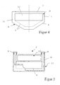
- FIG. 4 is the main building block 2 off FIG. 3 (alternatively FIG. 1 ) in cross-section with a chamfered bottom 6, which is double-walled 5, and a hollow section 7 is shown.
- the main building block 2 consists of an outer 2.1 and an inner area 2.2.
- the outer region 2.1 is formed as a trough 2.a and down V-shaped.
- the inner area 2.2, the actual crew compartment, is completely enclosed by a cabin or safety cell 9, 11 and is suspended in the outer part, the housing part 10, and fastened to the upper edge of the outer area 2.1.
- FIG. 5 the principle of the suspended cabin 9 is shown, which is mounted as a safety cell 9 by means of elastic suspensions 8 in the housing part 10.
- the housing part 10 has a plastically deformable support structure.
- the material of this cabin 9 is preferably aluminum to catch secondary splinters.
- the entire front module 1 is torn off or blown off.
- the entire axis 1a and the drive 20, 1c separated from the vehicle 4 without hitting the bottom of the main block 2, since the blocks 1, 2, 3 have a vertical dividing line.
- the residual impulse which then flows into the central main module 2, is converted by the double-walled construction in the lower part into deformation energy. Thereafter, the impulse hits thin-walled carriers in the upper area, which collapse.
- the then remaining residual pulse hits the elastic bearings or suspension 8 on the roof of the cabin 9, 11. There, the impulse is so long and flat that mechanical springs or similar.
- front and / or rear building block 1, 3 may have beveled floors that correspond to the bottom 6 of the main block 2.
- each wheel axle is provided with a drive motor and constitutes a separate separable segment.
Landscapes
- Engineering & Computer Science (AREA)
- General Engineering & Computer Science (AREA)
- Chemical & Material Sciences (AREA)
- Combustion & Propulsion (AREA)
- Transportation (AREA)
- Mechanical Engineering (AREA)
- Arrangement Or Mounting Of Propulsion Units For Vehicles (AREA)
- Body Structure For Vehicles (AREA)
- Hybrid Electric Vehicles (AREA)
Description
- Die Erfindung bezieht sich auf ein Fahrzeug mit Schutz gegen die Wirkung einer Landmine, insbesondere ein gepanzertes Radfahrzeug, für den Schutz von Personen sowie auch des Fahrzeuggehäuses in gepanzerten Fahrzeugen insgesamt gegen die Wirkung der Explosion von Minen, die auf oder im Erdboden verlegt sind. Bekannt sind dabei zwei- und mehrachsige Fahrzeuge.
- Diese Fahrzeuge haben am Chassis in der Regel einen glatten Unterboden und eine möglichst hohe Bodenfreiheit zwischen Unterboden und Erdboden, die von entsprechend ausgebildeten Rad- oder Kettenfahrwerken sichergestellt wird, damit sich das Fahrzeug auch im Gelände möglichst ungehindert fortbewegen kann. Die brisante Druckwirkung der unter dem Fahrzeug explodierenden Mine wirkt auf den relativ großflächigen Fahrzeug- oder Wannenboden, verformt und beschädigt diesen und kann erhebliche Schäden im Fahrzeug verursachen.
- Aus der
DE 31 19 786 A1 ist es zum Beispiel bekannt, zum Schutz gegen Minen auf der Unterseite des Fahrzeugs flächige Panzerungselemente anzubringen. - In der
DE 196 31 715 C2 ist der Fahrzeugboden mit einem keil- bzw. V- förmig zum Boden ausgebildeten Deflektor ausgerüstet, wobei im freien Volumen zwischen Deflektor und der Unterseite des Fahrzeugs zur Abstützung von innen und Gegenwirkung gegen die Explosion ein füllbarer Gassack angeordnet sein kann. - In der
DE 196 53 283 C1 wird eine Raumzelle als Besatzungsraum im Fahrzeuggehäuse separat elastisch aufgehängt, um damit auch Schockwirkungen, die von außen auf das Fahrzeug wirken, in Bezug auf die Personen im Fahrzeug zu beseitigen. - Aus der nach veröffentlichten
DE 10259918 A1 ist eine Minenschutzvorrichtung insbesondere für Radfahrzeuge bekannt, bei der aus einer detektierten Schockwelle / Körperschallwelle bzw. Blastwelle ein Detektionssignal von einer Zünd- und Auswerteeinheit erfasst wird, die an ein pyrotechnisches Trennelement angeschlossen ist und zu einer Trennung der Radbaugruppe bzw. des Rades von der Fahrzeugstruktur führt. Die pyrotechnische Trennung der Tragstruktur kann durch eine Schneidladung oder durch geeignete Ausführungen der Trennstelle mittels pyrotechnischen Trennschrauben erfolgen. - In der
WO 02/47958 A2 - Aus der
DE 102 33 274 A1 ist ein aus Einzelsegmenten aufgebautes gepanzertes Radfahrzeug bekannt, welches aus zwei Segmenten, einem Fahrsegment und einem Missionssegment, besteht und elektrische Antriebsmotoren in den Radnarben beider Segmente aufweist. Im hinteren Missionssegment sind Batterien zur Versorgung der Antriebsmotoren vorgesehen. - Die
US 4, 031. 807 A beschreibt ein geländefähiges Fahrzeug, dass aus einem mittleren Chassis besteht, an dessen beiden Enden je ein sich quer und längs zur Fahrtrichtung gerichtete Achse schwenkbares Fahrgestell angeordnet sind. Zwischen diesem Chassis und den Fahrgestellen sind Steuermittel zur Steuerung der Neigung der Fahrgestelle gegenüber dem Chassis um die quer zur Fahrtrichtung gerichtete Achse vorgesehen. Im vorderen als auch im hinteren Fahrgestell ist jeweils ein Gruppenantrieb eingebunden. Ein besonderer Minenschutz für die Besatzung ist nicht angedacht. - Aufgabe der Erfindung ist es, ein weiteres Schutzsystem auszubilden, dass eine Restmobilität für ein Fahrzeug erhalten bleibt, wenn dieses durch eine überfahrene Mine oder dergleichen einen Defekt erfährt.
- Diese Aufgabe wird erfindungsgemäß durch die Merkmale des Anspruchs 1 gelöst. Weitere bevorzugte Ausgestaltungen sind in den Unteransprüchen enthalten.
- Der Erfindung liegt die Idee zugrunde, front- und heckseitig jeweils einen elektrischen Antriebsmotor oder einen elektrischen und einen normalüblichen Antriebsmotor unterzubringen. Beim Fahrzeug mit normalüblichem Antrieb ist vorgesehen, dass mittels eines Verbrennungsmotors mechanisch die Räder einer ersten Fahrzeugachse angetrieben werden und ein separater elektrischer Antrieb eine zweite Fahrzeugachse antreiben kann. Dabei kann der Elektromotor seinen Strom aus einem Generator, der am Verbrennungsmotor angebaut ist, beziehen oder aus einem separaten elektrischen Energieerzeuger oder aus Batterien, die vorher aufgeladen wurden und entsprechend Strom für eine gewisse Beweglichkeit speichern können. Auch andere Speicher wie hochkapazitive Kondensatoren können hierbei zum Einsatz kommen. Derartige hybride Antriebe sind beispielsweise aus der
DE 197 18 709 A1 bekannt. Es ist jedoch vorgesehen, dass das eine Antriebssystem das andere ersetzt, wenn dieses andere ausgefallen ist, um eine Restmobilität insbesondere in Gefahrensituationen schaffen zu können, um sich dadurch selbständig aus dem direkten Gefahrenbereich einer Minensperre entfernen zu können. Bei Nutzung zweier elektrischer Antriebe ist einer im Frontbereich des Fahrzeugs neben der Vorderachse und der Lenkung eingebunden. Im Heckbereich ist dann neben der Hinterachse gleichfalls ein Antriebsmotor vorhanden. Dies hat den Vorteil, dass ein Frontmotor und ein Heckmotor gleichzeitig betrieben werden können, so dass ein redundanter Antrieb geschaffen und auch eine Restmobilität sichergestellt werden kann. - Für eine bessere Schutzwirkung ist das Fahrzeug in mehrere Bausteine getrennt bzw. unterteilt, die miteinander und voneinander loslösbar verbunden sind. Dieses Fahrzeug setzt sich dabei aus einem mittlerer Baustein, dem sogenannten Hauptbaustein, sowie einem Front- und Heckbaustein bzw. -teil zusammen. Heck- und Frontteil können an den mittleren Baustein angeflanscht oder mittels Sprengbolzen lösbar befestigt sein. Die Sprengbolzen werden mittels einer eingebauten Ladung gezündet und können so abgesprengt werden. Die Verbindung der Bausteine mit Sollbruchstellen aufweisenden Bolzen ist ebenfalls möglich. Die Radachsen werden vorzugsweise zudem so plaziert, dass sie nicht unter dem Mannschaftsraum liegen.
- Der eigentliche Mannschaftsraum wird in Weiterbildung als Kabine oder Schutzzelle in das Fahrzeuggehäuse, dem Hauptbaustein, eingehängt und schwingungsmäßig entkoppelt. Die Tragstruktur wir plastisch deformierbar gehalten und der V-förmige Unterboden wird ohne Durchbrüche wie zum Beispiel Türen aufgebaut. Es erfolgt also eine elastische Aufhängung im Dachbereich des Hauptbausteins, der aus plastisch verformbaren, Energie aufnehmenden, dünnwandigen Hohlprofilen besteht.
- Ein innerhalb des Hauptbausteins zwischen dem V-förmigen Boden der Tragstruktur und der (unten) abgeflachten Kabine entstehender Raum kann dazu dienen, die Antriebswelle und / oder Kabel aufzunehmen.
- Die Bausteine sind so konstruiert, dass Minensprengungen möglichst geringe schädliche Auswirkungen haben.
- Des Weiteren ist durch das einfache Anbringen der Kabine ein einfaches Aushängen der einen und das einfache Einhängen einer anderen Kabine möglich. Dies erleichtert eine Umrüstung der Hauptkabine in eine neue Fahrzeug-Variante.
- Vorgeschlagen wird also ein militärisches Radfahrzeug mit hohem Minenschutz, bei welchem die jede der vorhandenen Radachsen mit Antrieben versehen ist und eine vorzugsweise Dreiteilung im Fahrzeugaufbau in einen Frontbaustein, einen Hauptbaustein und einen Heckbaustein eine Restmobilität gewährt, wenn der Frontbaustein oder der Heckbaustein bzw. Teile davon nach dem Überfahren einer Mine vom Hauptbaustein abgetrennt werden.
- Weitere Vorteile ergeben sich aus den Unteransprüchen.
- Ausführungsbeispiele der Erfindung sind in den Zeichnungen schematisch dargestellt und werden im folgenden näher beschrieben. Es zeigen:
- Figur 1:
- Perspektivansicht eines Beispielfahrzeugs,
- Figur 2:
- Seitenansicht eines Fahrzeugs,
- Figur 3:
- Darstellung des Fahrzeugs in Seitenansicht nach dem Überfahren einer Mine,
- Figur 4:
- Querschnitt einer Sicherheitszelle für die Besatzung,
- Figur 5:
- Seitenansicht der aufgehängten Sicherheitszelle.
- In
Figur 1 wird ein erfindungsgemäßes zweiachsiges Beispielfahrzeug 4 mit mehreren Bausteinen, wie Frontbaustein 1, Hauptbaustein 2 und Heckbaustein 3, gezeigt. Mit 12 gekennzeichnet ist ein Ausstieg für eine mit 13 gekennzeichnete Besatzung. - Das in
Figur 2 von der Seite gezeigte Fahrzeug 4 besitzt im Frontbaustein 1, hier auch als Motorbaustein bezeichnet, eine Radachse 1a mit einem rechten und einem linken vorderen Rad 1b. Im Hauptbaustein 2, hier auch als Mannschaftsraumbaustein bezeichnet, befindet sich eine Radachse 3a mit einem rechten und linken hinteren Rad 3b. Die Radachsen 1a, 3a sind hierbei vorzugsweise nicht wie üblich unter dem Mannschaftsraumbaustein 2 angeordnet. Motor- und Heckbaustein 1, 3 können am Mannschaftraumbaustein 2 angeflanscht bzw. lösbar mittels skizzenhaft angedeuteten Bolzen / Sprengbolzen 4a mit diesem verbunden sein. Der Frontbaustein 1 weist neben einer nicht näher dargestellten Lenkung einen Antriebsmotor 1c sowie einen Verbrennungsmotor 20 und einen daran befestigten, beispielsweise angeflanschten Stromerzeuger 21, hier einen Generator auf. Auch im Heckbaustein 3 ist ebenfalls ein Antriebsmotor 3c vorgesehen. Der Heckbaustein 3 weist zusätzlich eine Batterie 22 auf, die mit dem Antriebsmotor 3c verbunden ist. Die Stromzuführung Generator 22 zum Antriebsmotor 1c und Batterie 23 zum Antriebsmotor 3c erfolgt herkömmlich über Stromleitungen 23. - In allen hier beschriebenen Ausführungen des Fahrzeugs 4 wird bevorzugt um die Räder 1b, 3b senkrecht nach oben ein Freiraum eingehalten.
- In
Figur 3 ist ein Treffer beispielsweise durch ein Überfahren einer nicht näher dargestellten Mine am Fahrzeug 4 symbolisch aufgezeigt. In dieser Situation ist das Frontteil 1 vom Hauptbaustein 2 abgesprengt worden. Der verbleibende Rest des Fahrzeugs 4' hat hier jedoch einen eigenen Antrieb 3c, der dem Fahrzeug 4' eine Restmobilität gewährleistet. - In
Figur 4 ist der Hauptbaustein 2 ausFigur 3 (alternativFigur 1 ) im Querschnitt mit einem abgeschrägten Boden 6, welcher doppelwandig 5 ausgeführt ist, und einem Hohlprofil 7 dargestellt. - Der Hauptbaustein 2 besteht aus einem äußeren 2.1 und einem inneren Bereich 2.2. Der äußere Bereich 2.1 ist als Wanne 2.a und nach unten hin V-förmig ausgebildet. Der innere Bereich 2.2, der eigentliche Mannschaftsraum, wird durch eine Kabine oder Sicherheitszelle 9, 11 voll umschlossen und ist in den äußeren Teil, dem Gehäuseteil 10, eingehängt und an der oberen Kante des äußeren Bereichs 2.1 befestigt.
- In
Figur 5 ist das Prinzip der aufgehängten Kabine 9 gezeigt, wobei diese als Sicherheitszelle 9 mittels elastischen Aufhängungen 8 in dem Gehäuseteil 10 eingehängt ist. Das Gehäuseteil 10 weist eine plastisch deformierbare Tragstruktur auf. Das Material dieser Kabine 9 ist vorzugsweise Aluminium, um Sekundärsplitter aufzufangen. - Bei einer Minenexplosion trifft eine nicht näher dargestellte Mine beispielsweise ein Rad bzw. beide Räder 1b, welche sich lösen und nach oben wegfliegen können. In solchen Fällen ist vorgesehen, dass der ganze Frontbaustein 1 abreißen bzw. abgesprengt wird. Dabei wird vorzugsweise die gesamte Achse 1a und der Antrieb 20, 1c von Fahrzeug 4 getrennt, ohne von unten in den Hauptbaustein 2 zu schlagen, da die Bausteine 1, 2, 3 eine vertikale Trennlinie haben. Der Restimpuls, der danach in den mittleren Hauptbaustein 2 fließt, wird durch die doppelwandige Bauweise im unteren Bereich in Verformungsenergie umgewandelt. Danach trifft der Impuls auf dünnwandige Träger im oberen Bereich, die sich zusammenstauchen. Der dann noch vorhandene Restimpuls trifft auf die elastischen Lager bzw. Aufhängung 8 am Dach der Kabine 9, 11. Dort ist der Impuls schon so lang und flach, dass mechanische Federn o.ä. eingesetzt werden können. Der Restimpuls, der über diese Federn in das Dach der Kabine 9, 11 fließt, ist weit genug gedämpft, um die Besatzung nicht mehr zu verletzen. Mittels des verbleibenden Antriebs 3c (oder, wenn der Heckbaustein 3 abgetrennt wurde, mittels 1c bzw. in Kombination mit Verbrennungsmotor 20) kann sich die Mannschaft des Fahrzeugs 4 bzw. den Resten des Fahrzeugs 4' eigenständig aus der Gefahrenzone in Sicherheit bringen.
- Es versteht sich, dass auch Front- und /oder Heckbaustein 1, 3 abgeschrägte Böden besitzen können, die dem Boden 6 des Hauptbausteins 2 entsprechen.
- Die vorgehende Beschreibung bezieht sich auf ein zweiachsiges Fahrzeug 4. Die Lösung läßt sich auch an mehrachsigen Fahrzeugen verwirklichen, die in mehreren Bausteinen unterteilt voneinander lösbar sind wie beschrieben. Diese Unterteilung kann dann auch innerhalb des Frontbauteils 1 oder des Heckbauteils 3 erfolgen. Beispielsweise kann vorgesehen sein, dass jede Radachse mit einem Antriebsmotor versehen ist und ein eigenes abtrennbares Segment darstellt.
-
- 1
- Front- bzw. Motorbaustein
- 1a
- Radachse
- 1b
- Rad
- 2
- Hauptbaustein, Mannschaftsraum- Baustein
- 2.1
- äußerer Bereich
- 2.2
- innerer Bereich
- 2.a
- Wanne
- 3
- Heckbaustein
- 3a
- Radachse
- 3b
- Rad
- 4
- Fahrzeug
- 4.a
- Bolzen / Sprengbolzen
- 5
- doppelwandiger Boden
- 6
- abgeschrägter Boden
- 7
- Hohlprofil
- 8
- elastische Aufhängung
- 9
- Sicherheitszelle
- 10
- Gehäuseteil
- 11
- Sicherheitszelle
- 20
- Verbrennungsmotor
- 21
- Generator
- 22
- Batterie
- 23
- Stromzuführung
Claims (12)
- Fahrzeug (4) mit Schutz gegen die Wirkung einer Landmine, insbesondere gepanzertes Radfahrzeug, bestehend aus mehreren Bausteinen (1, 2, 3), wobei- ein Frontbaustein (1) mit wenigstens einer Radachse (1a) und ein Heckbaustein (3) mit wenigstens einer Radachse (3a) an einem Hauptbaustein (2) vorn und hinten an diesem befestigt sind, dadurch gekennzeichnet dass,- der Hauptbaustein (2) einen V-förmigen Unterboden (6) besitzt,- ein elektrischer Antriebsmotor (1c) und ein Verbrennungsmotor (20) im Frontbaustein (1) und ein elektrischer Antriebsmotor (3c) im Heckbaustein (1, 3) oder- ein elektrischer Antriebsmotor (1c) im Frontbaustein (1) und ein elektrischer Antrieb (3c) und ein Verbrennungsmotor (20) im Heckbaustein (3) vorhanden sind,- der Front-(1) und der Heckbaustein (3) über Mittel (4a) lösbar am Hauptbaustein (2) befestigt sind, sodass,- wenn das Fahrzeug die Landmine überfährt, bei einer Minenexplosion der Front- oder Heckbaustein (1, 3) vom Hauptbaustein (2) getrennt wird, und- die jeweils wenigstens eine Radachse (1a, 3a) mittels des verbliebenen Antriebes (1c, 3c, 20) im Front- oder im Heckbaustein (1, 3) angetrieben und der Front- oder Heckbaustein (1, 3) mit dem Hauptbaustein (2) eigenständig aus der Gefahrenzone in Sicherheit gebracht wird.
- Fahrzeug nach Anspruch 1, dadurch gekennzeichnet, dass die Mittel (4a) Bolzen, welche Sollbruchstellen aufweisen, und / oder Sprengbolzen, welche mittels einer eingebauten Ladung gezündet und abgesprengt werden können, sind.
- Fahrzeug nach einem der Ansprüche 1 oder 2, dadurch gekennzeichnet, dass ein Freiraum senkrecht nach oben über den Rädern (1b, 3b) und den Radachsen (1a, 3a) eingehalten ist und die Radachsen (1a, 3a) des Fahrzeugs (4) so platziert sind, dass sie nicht unter dem Hauptbaustein (2) angebracht sind.
- Fahrzeug nach einem der vorgenannten Ansprüche 1 bis 3, dadurch gekennzeichnet, dass das Gehäuse des Hauptbausteins (2) als Wannengehäuse (2a) doppelwandig ausgeführt ist und aus dünnem Stahlblech besteht.
- Fahrzeug nach Anspruch 4, dadurch gekennzeichnet, dass das Wannengehäuse (2a) aus Hohlprofilen (7) gebildet wird.
- Fahrzeug nach einem der vorgenannten Ansprüche 1 bis 5, dadurch gekennzeichnet, dass der Hauptbaustein eine Kabine und / oder Schutzzelle (9, 11) enthält, welche mittels elastischer Aufhängungen (8) im Gehäuseteil (10) eingehängt und schwingungsmäßig entkoppelt wird.
- Fahrzeug nach Anspruch 6, dadurch gekennzeichnet, dass das Gehäuseteil (10) eine plastisch deformierbare Tragstruktur aufweist.
- Fahrzeug nach einem der vorgenannten Ansprüche 1 bis 7, dadurch gekennzeichnet, dass die Kabine (9, 11) aus dickwandigem, zähen Material, wie Aluminium besteht.
- Fahrzeug nach einem der vorgenannten Ansprüche 1 bis 8, dadurch gekennzeichnet, dass das Fahrzeug durch einfaches Aushängen der Kabine (9, 11) und Einhängen einer anderen Kabine (9, 11) in eine neue Fahrzeug-Version umgerüstet werden kann.
- Fahrzeug nach einem der Ansprüche 1 bis 9, dadurch gekennzeichnet, dass der elektrische Antriebsmotor (1c) im Frontbaustein (1) über einen Stromerzeuger (21) mit dem Verbrennungsmotor (20) und der elektrische Antrieb (3c) im Heckbaustein (3) mit einer Batterie (22) oder dergleichen mittels Stromleitungen (23) verbunden ist.
- Fahrzeug nach einem der Ansprüche 1 bis 10, dadurch gekennzeichnet, dass der elektrische Antriebsmotor (3c) im Heckbaustein (3) über einen Stromerzeuger (21) mit dem Verbrennungsmotor (20) und der elektrische Antrieb (1c) im Frontbaustein (1) mit einer Batterie (22) oder dergleichen mittels Stromleitungen (23) verbunden ist.
- Fahrzeug nach einem der Ansprüche 1 bis 11, dadurch gekennzeichnet, dass ein mehrachsiges Fahrzeug in mehrere Bausteine unterteilt voneinander lösbar ist, wobei die Unterteilung auch innerhalb des Frontbausteins (1) oder des Heckbausteins (3) erfolgen kann, jede Radachse mit einem Antriebsmotor versehen ist und ein eigenes abtrennbares Segment darstellt.
Applications Claiming Priority (4)
| Application Number | Priority Date | Filing Date | Title |
|---|---|---|---|
| DE102004024819 | 2004-02-11 | ||
| DE102004024819 | 2004-02-11 | ||
| DE102004026237 | 2004-05-28 | ||
| DE102004026237A DE102004026237A1 (de) | 2004-02-11 | 2004-05-28 | Fahrzeug mit Schutz gegen die Wirkung einer Landmine |
Publications (2)
| Publication Number | Publication Date |
|---|---|
| EP1564518A1 EP1564518A1 (de) | 2005-08-17 |
| EP1564518B1 true EP1564518B1 (de) | 2011-06-15 |
Family
ID=34702143
Family Applications (1)
| Application Number | Title | Priority Date | Filing Date |
|---|---|---|---|
| EP04029313A Expired - Lifetime EP1564518B1 (de) | 2004-02-11 | 2004-12-10 | Fahrzeug mit Schutz gegen die Wirkung einer Landmine |
Country Status (4)
| Country | Link |
|---|---|
| US (1) | US7228927B2 (de) |
| EP (1) | EP1564518B1 (de) |
| AT (1) | ATE513178T1 (de) |
| DE (1) | DE102004026237A1 (de) |
Families Citing this family (55)
| Publication number | Priority date | Publication date | Assignee | Title |
|---|---|---|---|---|
| DE102004006819B4 (de) * | 2004-02-11 | 2007-01-04 | Rheinmetall Landsysteme Gmbh | Fahrzeug mit Schutz gegen die Wirkung einer Landmine |
| IL162945A0 (en) * | 2004-07-08 | 2005-11-20 | Plasan Kibbutz Sasa | Truck cabin armor |
| DE202005006655U1 (de) * | 2005-04-12 | 2005-08-25 | Drehtainer Gmbh Spezial Container- Und Fahrzeugbau | Geschütztes Fahrzeug oder Schiff |
| US7401540B1 (en) * | 2006-08-21 | 2008-07-22 | Robert William Kocher | Highly survivable urban utility vehicle (HSUUV) |
| DE102006051870A1 (de) | 2005-11-18 | 2007-05-24 | Rheinmetall Landsysteme Gmbh | Gepanzertes Fahrzeug |
| US20070186762A1 (en) * | 2005-12-22 | 2007-08-16 | Blackwater Lodge And Training Center Llc | Armored vehicle with blast deflecting hull |
| FR2897677B1 (fr) * | 2006-02-17 | 2010-05-28 | Giat Ind Sa | Dispositif de protection d'un plancher de vehicule |
| WO2008060318A2 (en) * | 2006-03-23 | 2008-05-22 | Walters & Clune, Llc | Modular vehicle system and method |
| DE102006034689A1 (de) * | 2006-07-24 | 2008-01-31 | Rheinmetall Landsysteme Gmbh | Schutzeinrichtung für ein militärisches Fahrzeug, welches als Unterstützungsfahrzeug fungiert und alle pionier- und bergtechnischen Arbeiten ausführen kann |
| USD590743S1 (en) * | 2006-08-28 | 2009-04-21 | Walters & Clune, Llc | Modular vehicle |
| US20080066613A1 (en) * | 2006-09-15 | 2008-03-20 | Lockheed Martin Corporation | Perforated hull for vehicle blast shield |
| US20080173167A1 (en) * | 2006-09-15 | 2008-07-24 | Armor Holdings | Vehicular based mine blast energy mitigation structure |
| DE102007002576A1 (de) * | 2007-01-11 | 2008-07-17 | Rheinmetall Landsysteme Gmbh | Entkoppelte Pedaleinheit in einem minengeschützten, insbesondere militärischen Fahrzeug |
| FR2916528B1 (fr) * | 2007-05-23 | 2009-07-17 | Nexter Systems Sa | Vehicule blinde leger modulaire et cabine mise en oeuvre dans un tel vehicule |
| US8365649B1 (en) * | 2008-02-13 | 2013-02-05 | Andrews Mark D | Multi-layered composite belly plate and method of making and using |
| DE102008019656A1 (de) * | 2008-04-18 | 2009-10-22 | Krauss-Maffei Wegmann Gmbh & Co. Kg | Militärisches Kraftfahrzeug |
| DE102008020555A1 (de) | 2008-04-22 | 2009-10-29 | Esw Gmbh | Redundantes Antriebssystem für Hybridfahrzeuge |
| US8430196B2 (en) * | 2008-12-29 | 2013-04-30 | Hal-Tech Limited | Deformable armored land vehicle |
| US8205703B2 (en) * | 2008-12-29 | 2012-06-26 | Hal-Tech Limited | Deformable modular armored combat system |
| RU2399856C1 (ru) * | 2009-01-11 | 2010-09-20 | Открытое акционерное общество Конструкторское бюро транспортного машиностроения (ОАО КБТМ) | Унифицированное низкосилуэтное шасси для военных гусеничных машин (варианты) |
| IL196456A0 (en) * | 2009-01-12 | 2009-12-24 | Shlomo Birger | Uderbelly of armord vehicle |
| DE102009014401A1 (de) | 2009-03-26 | 2010-09-30 | Skoff, Gerhard, Dr. | Knickgelenktes Fahrzeug, insbesondere gepanzertes Fahrzeug |
| IL198017A (en) | 2009-04-05 | 2015-02-26 | Rafael Advanced Defense Sys | Means and method of protecting a fighter cell in a wheeled vehicle against explosives |
| US8656823B2 (en) * | 2009-06-05 | 2014-02-25 | Fox Factory, Inc. | Methods and apparatus for suspending a vehicle shield |
| IL202275A0 (en) | 2009-11-23 | 2010-11-30 | Plasan Sasa Ltd | A system for providing protection against an explosive threat |
| US8499677B2 (en) | 2009-11-30 | 2013-08-06 | General Dynamics Land Systems—Canada Corporation | W-shaped hull |
| US8584572B2 (en) * | 2009-12-18 | 2013-11-19 | Hardwire, Llc | Vehicle with structural vent channels for blast energy and debris dissipation |
| US8578834B2 (en) * | 2009-12-18 | 2013-11-12 | Hardwire, Llc | Vehicle with structural vent channels for blast energy and debris dissipation |
| DE102010008828B4 (de) * | 2010-02-22 | 2012-03-01 | Rheinmetall Landsysteme Gmbh | Schutzsystem für ein Fahrzeug oder dergleichen |
| GB2480081B (en) * | 2010-05-05 | 2014-10-29 | Np Aerospace Ltd | Vehicle |
| US8616617B2 (en) * | 2010-10-25 | 2013-12-31 | BAE Systems Tactical Vehicle Systems L.P. | Lightweight blast resistant armored cab for vehicles |
| US8752470B2 (en) * | 2011-01-31 | 2014-06-17 | Ideal Innovations Incorporated | Reduced size, symmetrical and asymmetrical crew compartment vehicle construction |
| DE102011000974A1 (de) | 2011-02-28 | 2012-08-30 | Krauss-Maffei Wegmann Gmbh & Co. Kg | Fahrzeug, insbesondere militärisches Fahrzeug |
| USD661224S1 (en) * | 2011-03-14 | 2012-06-05 | Marius Allaire | All-terrain vehicle |
| US8677876B2 (en) * | 2011-07-16 | 2014-03-25 | Kevin Mark Diaz | 4D simultaneous robotic containment with recoil |
| US8240239B1 (en) | 2011-07-16 | 2012-08-14 | Kevin Mark Diaz | Green energy mine defeat system |
| US9045014B1 (en) | 2012-03-26 | 2015-06-02 | Oshkosh Defense, Llc | Military vehicle |
| USD966958S1 (en) | 2011-09-27 | 2022-10-18 | Oshkosh Corporation | Grille element |
| DE102012001995B4 (de) * | 2012-02-03 | 2019-09-19 | Rheinmetall Man Military Vehicles Gmbh | Fahrzeug mit einem Zwischenboden |
| US10495419B1 (en) * | 2017-04-27 | 2019-12-03 | Oshkosh Defense, Llc | Vehicle armor systems and methods |
| US12491943B1 (en) | 2013-03-10 | 2025-12-09 | Oshkosh Defense, Llc | Systems and methods for a military vehicle |
| US9303715B2 (en) | 2013-03-10 | 2016-04-05 | Oshkosh Defense, Llc | Limiting system for a vehicle suspension component |
| WO2015078996A1 (en) * | 2013-11-27 | 2015-06-04 | Nederlandse Organisatie Voor Toegepast-Natuurwetenschappelijk Onderzoek Tno | Blast-protection element |
| US10184553B2 (en) * | 2014-02-12 | 2019-01-22 | Pratt & Miller Engineering and Fabrication, Inc. | Blast mitigating differential housing |
| EP3280676B1 (de) | 2016-04-08 | 2018-11-07 | Oshkosh Corporation | Niveauregulierungssystem für ein lift-gerät |
| US10173464B2 (en) * | 2016-06-12 | 2019-01-08 | Monolithic 3D, Inc. | Efficient wheel |
| US20180058820A1 (en) * | 2016-08-24 | 2018-03-01 | Pratt & Miller Engineering and Fabrication, Inc. | Multiple layer hull |
| US10647324B2 (en) * | 2016-09-28 | 2020-05-12 | Polaris Industries Inc. | Systems and methods for control of two independent powertrains in a vehicle |
| US10745065B2 (en) * | 2018-04-16 | 2020-08-18 | Howe & Howe Inc. | Vehicle with pneumatically suspended operator compartment |
| AU2020364175B2 (en) * | 2019-10-11 | 2024-02-01 | Howe & Howe Inc. | Modular tracked vehicle |
| US11731697B2 (en) | 2020-03-05 | 2023-08-22 | Howe & Howe Inc. | Vector steering for tracked vehicle |
| DE102021126173A1 (de) * | 2021-10-08 | 2023-04-13 | Rheinmetall Landsysteme Gmbh | Gepanzertes Fahrzeug mit Notausstiegsluke |
| DE102021126174A1 (de) * | 2021-10-08 | 2023-04-13 | Rheinmetall Landsysteme Gmbh | Gepanzertes Fahrzeug mit Notausstiegsluke |
| DE102022103396A1 (de) * | 2022-02-14 | 2023-08-17 | Rheinmetall Landsysteme Gmbh | Anordnung und geschütztes Fahrzeug |
| DE102022103469A1 (de) * | 2022-02-15 | 2023-08-17 | Audi Aktiengesellschaft | Antriebskonzept für gepanzerte Elektrofahrzeuge |
Family Cites Families (32)
| Publication number | Priority date | Publication date | Assignee | Title |
|---|---|---|---|---|
| US2716040A (en) * | 1949-01-26 | 1955-08-23 | Barenyi Bela | Motor vehicle having hinged end sections and attached lifting means |
| DE2430913A1 (de) * | 1974-06-27 | 1976-01-08 | Jourdan Klaus Dipl Ing | Knickgelenktes panzerbares bzw. gepanzertes radfahrzeug |
| FR2281263A1 (fr) * | 1974-08-08 | 1976-03-05 | Secmafer Sa | Engin tous terrains |
| FR2285591A1 (fr) * | 1974-09-20 | 1976-04-16 | Secmafer Sa | Char d'assaut |
| BE843531A (fr) * | 1976-06-29 | 1984-05-17 | Acec | Engin blindé auto-propulsé. |
| US4280393A (en) * | 1978-04-14 | 1981-07-28 | Creusot-Loire | Light weight armored vehicle |
| US4351558A (en) * | 1979-04-23 | 1982-09-28 | Mueller Frederick N | Truck body construction |
| JPS5951472B2 (ja) * | 1979-11-16 | 1984-12-14 | トヨタ自動車株式会社 | 組立式自動車 |
| DE3119786A1 (de) | 1981-05-19 | 1982-12-23 | Harry 7311 Hochdorf Apprich | Vorrichtung zur sicherung von flaechengebilden gegen die wirkung von sprengkoerpern |
| FR2510737A1 (fr) * | 1981-08-03 | 1983-02-04 | Fives Cail Babcock | Vehicule blinde de reconnaissance et de combat |
| DE3206794A1 (de) * | 1982-02-25 | 1983-09-01 | Hermann Dr.-Ing. 3302 Cremlingen Klaue | Gepanzertes kampffahrzeug |
| EP0278479B1 (de) * | 1987-02-10 | 1993-05-12 | Nissan Motor Co., Ltd. | Fahrzeugbau, insbesondere Rahmen |
| GB8709125D0 (en) * | 1987-04-15 | 1987-05-20 | Siren A O | All-terrain hydrofoil train |
| DE3719289C1 (en) * | 1987-06-10 | 1988-12-08 | Bundesrep Deutschland | Small combat vehicle system, configured in a modular manner, for wheeled or tracked vehicles (track-laying vehicles |
| US5176213A (en) * | 1987-12-09 | 1993-01-05 | Aisin Aw Co., Ltd. | Driving force distribution system for hybrid vehicles |
| US5245738A (en) * | 1988-09-19 | 1993-09-21 | Tini Alloy Company | Method for securing together and non-explosively separating multiple components |
| US5401056A (en) * | 1994-03-11 | 1995-03-28 | Eastman; Clayton | Modular vehicle constructed of front, rear and center vehicular sections |
| US5866839A (en) * | 1994-03-21 | 1999-02-02 | Ohayon; Shalom | High performance armor protection system for tank crews and fighting vehicles |
| US5558588A (en) * | 1995-02-16 | 1996-09-24 | General Motors Corporation | Two-mode, input-split, parallel, hybrid transmission |
| JP3861321B2 (ja) | 1996-05-02 | 2006-12-20 | トヨタ自動車株式会社 | ハイブリッド車 |
| DE19619865C2 (de) * | 1996-05-17 | 1999-07-29 | Mak System Gmbh | Umrüstbares straßen- und geländegeeignetes Fahrzeug |
| US5663520A (en) * | 1996-06-04 | 1997-09-02 | O'gara-Hess & Eisenhardt Armoring Co. | Vehicle mine protection structure |
| DE19631715C2 (de) * | 1996-08-06 | 2000-01-20 | Bundesrep Deutschland | Schutzsystem für Fahrzeuge gegen Minen |
| DE19653283C1 (de) * | 1996-12-20 | 1998-06-25 | Mak System Gmbh | Panzerfahrzeug |
| DE19756683C1 (de) * | 1997-12-19 | 1999-06-02 | Mak System Gmbh | Fahrantrieb für Kettenfahrzeuge |
| US7007761B1 (en) * | 1999-05-21 | 2006-03-07 | Johnson Iv John J | Emergency response vehicle |
| US6435071B1 (en) | 2000-10-26 | 2002-08-20 | John Bruce Campbell | Vehicle for traveling through hostile environments |
| DE10117575A1 (de) * | 2001-04-07 | 2002-10-10 | Krauss Maffei Wegmann Gmbh & C | Einrichtung zum Schutz der Besatzung eines militärischen Fahrzeugs bei Minenexplosion |
| JP4029592B2 (ja) * | 2001-09-05 | 2008-01-09 | 株式会社日立製作所 | 補助駆動装置およびこれを搭載した自動車 |
| DE10233274A1 (de) * | 2002-07-23 | 2004-02-05 | Krauss-Maffei Wegmann Gmbh & Co.Kg | Aus Einzelsegmenten aufgebautes gepanzertes Radfahrzeug |
| DE10256918A1 (de) | 2002-12-05 | 2004-07-15 | Herding Gmbh Filtertechnik | Verfahren zum Klären von Abwasser unter Bildung von Überschussschlamm und entsprechende Abwasser-Kläranlage |
| DE10259918B4 (de) * | 2002-12-20 | 2005-06-23 | Rheinmetall Landsysteme Gmbh | Minenschutzeinrichtung, insbesondere für Radfahrzeuge |
-
2004
- 2004-05-28 DE DE102004026237A patent/DE102004026237A1/de not_active Withdrawn
- 2004-12-10 AT AT04029313T patent/ATE513178T1/de active
- 2004-12-10 EP EP04029313A patent/EP1564518B1/de not_active Expired - Lifetime
-
2005
- 2005-02-11 US US11/055,772 patent/US7228927B2/en not_active Expired - Lifetime
Also Published As
| Publication number | Publication date |
|---|---|
| ATE513178T1 (de) | 2011-07-15 |
| US7228927B2 (en) | 2007-06-12 |
| US20050284682A1 (en) | 2005-12-29 |
| EP1564518A1 (de) | 2005-08-17 |
| DE102004026237A1 (de) | 2005-11-10 |
Similar Documents
| Publication | Publication Date | Title |
|---|---|---|
| EP1564519B1 (de) | Minenschutz-Fahrzeugsystem | |
| EP1564518A1 (de) | Fahrzeug mit Schutz gegen die Wirkung einer Landmine | |
| EP1275928B1 (de) | Minenschutzboden für ein Panzerfahrzeug | |
| EP2959258B1 (de) | Militärisches fahrzeug mit einer führungseinheit | |
| DE102013218811B4 (de) | Anordnung zur Lagerung mindestens eines, in einer Aufnahmevorrichtung angeordneten Antriebsenergiespeichers in einem Kraftfahrzeug | |
| DE102008019656A1 (de) | Militärisches Kraftfahrzeug | |
| DE102009014401A1 (de) | Knickgelenktes Fahrzeug, insbesondere gepanzertes Fahrzeug | |
| DE19605230A1 (de) | Minenschutzvorrichtung | |
| DE102012021269A1 (de) | Fahrzeug mit einer das Einschlagen eines Vorderrades zulassenden Kinematik bei einem teilüberdeckten Frontalaufprall | |
| EP1293747A2 (de) | Sicherheitsboden in gepanzerten Fahrzeugen | |
| EP2354754A2 (de) | Kampfpanzer mit einer Besatzung im Turm | |
| EP2362177A2 (de) | Schutzsystem für ein Fahrzeug | |
| DE102012001995B4 (de) | Fahrzeug mit einem Zwischenboden | |
| DE10133147B4 (de) | Gepanzertes Transportfahrzeug | |
| DE102015112237B4 (de) | Amphibienfahrzeug | |
| EP2589919A1 (de) | Gepanzertes minengefährdetes Fahrzeug | |
| DE102021005104A1 (de) | Sicherheitssystem für ein zumindest teilweise elektrisch betriebenes Kraftfahrzeug, sowie Verfahren zum Betreiben eines Sicherheitssystems | |
| EP1291609B1 (de) | Gepanzertes Transportfahrzeug mit Batterie-Schwenkmechanismus | |
| DE102023123416B4 (de) | Anordnung eines elektrischen Energiespeichers in einem elektrisch antreibbaren Sonderschutzkraftwagen | |
| DE102023123418B4 (de) | Speichergehäuseschutz für einen elektrischen Energiespeicher eines elektrisch antreibbaren Sonderschutzkraftwagens, Anordnung sowie Verfahren | |
| DE102022115403B3 (de) | Anordnung einer Schutzplatte in einem Unterbodenbereich eines Sonderschutzkraftwagens | |
| WO2025045302A1 (de) | Schutzplatte für einen elektrischen energiespeicher eines elektrisch antreibbaren sonderschutzkraftwagens sowie anordnung | |
| EP4438995B1 (de) | Geschütztes fahrzeug | |
| EP4438998B1 (de) | Überrollschutzsystem und geschütztes fahrzeug | |
| WO2026057642A1 (de) | Fahrerhaus und nutzfahrzeug |
Legal Events
| Date | Code | Title | Description |
|---|---|---|---|
| PUAI | Public reference made under article 153(3) epc to a published international application that has entered the european phase |
Free format text: ORIGINAL CODE: 0009012 |
|
| 17P | Request for examination filed |
Effective date: 20050601 |
|
| AK | Designated contracting states |
Kind code of ref document: A1 Designated state(s): AT BE BG CH CY CZ DE DK EE ES FI FR GB GR HU IE IS IT LI LT LU MC NL PL PT RO SE SI SK TR |
|
| AX | Request for extension of the european patent |
Extension state: AL BA HR LV MK YU |
|
| RAP1 | Party data changed (applicant data changed or rights of an application transferred) |
Owner name: RHEINMETALL LANDSYSTEME GMBH |
|
| AKX | Designation fees paid |
Designated state(s): AT BE BG CH CY CZ DE DK EE ES FI FR GB GR HU IE IS IT LI LT LU MC NL PL PT RO SE SI SK TR |
|
| 17Q | First examination report despatched |
Effective date: 20061121 |
|
| GRAP | Despatch of communication of intention to grant a patent |
Free format text: ORIGINAL CODE: EPIDOSNIGR1 |
|
| REG | Reference to a national code |
Ref country code: DE Ref legal event code: R079 Ref document number: 502004012596 Country of ref document: DE Free format text: PREVIOUS MAIN CLASS: F41H0007020000 Ipc: F41H0007040000 |
|
| GRAS | Grant fee paid |
Free format text: ORIGINAL CODE: EPIDOSNIGR3 |
|
| RIC1 | Information provided on ipc code assigned before grant |
Ipc: F41H 7/04 20060101AFI20110311BHEP Ipc: B60K 6/48 20071001ALI20110311BHEP |
|
| GRAA | (expected) grant |
Free format text: ORIGINAL CODE: 0009210 |
|
| AK | Designated contracting states |
Kind code of ref document: B1 Designated state(s): AT BE BG CH CY CZ DE DK EE ES FI FR GB GR HU IE IS IT LI LT LU MC NL PL PT RO SE SI SK TR |
|
| REG | Reference to a national code |
Ref country code: GB Ref legal event code: FG4D Free format text: NOT ENGLISH Ref country code: CH Ref legal event code: EP |
|
| REG | Reference to a national code |
Ref country code: IE Ref legal event code: FG4D Free format text: LANGUAGE OF EP DOCUMENT: GERMAN |
|
| REG | Reference to a national code |
Ref country code: DE Ref legal event code: R096 Ref document number: 502004012596 Country of ref document: DE Effective date: 20110721 |
|
| REG | Reference to a national code |
Ref country code: CH Ref legal event code: NV Representative=s name: OK PAT AG PATENTE MARKEN LIZENZEN |
|
| REG | Reference to a national code |
Ref country code: NL Ref legal event code: T3 |
|
| REG | Reference to a national code |
Ref country code: SE Ref legal event code: TRGR |
|
| PG25 | Lapsed in a contracting state [announced via postgrant information from national office to epo] |
Ref country code: LT Free format text: LAPSE BECAUSE OF FAILURE TO SUBMIT A TRANSLATION OF THE DESCRIPTION OR TO PAY THE FEE WITHIN THE PRESCRIBED TIME-LIMIT Effective date: 20110615 |
|
| REG | Reference to a national code |
Ref country code: ES Ref legal event code: FG2A Ref document number: 2368140 Country of ref document: ES Kind code of ref document: T3 Effective date: 20111114 |
|
| REG | Reference to a national code |
Ref country code: GR Ref legal event code: EP Ref document number: 20110402151 Country of ref document: GR Effective date: 20111013 |
|
| PG25 | Lapsed in a contracting state [announced via postgrant information from national office to epo] |
Ref country code: SI Free format text: LAPSE BECAUSE OF FAILURE TO SUBMIT A TRANSLATION OF THE DESCRIPTION OR TO PAY THE FEE WITHIN THE PRESCRIBED TIME-LIMIT Effective date: 20110615 Ref country code: CY Free format text: LAPSE BECAUSE OF FAILURE TO SUBMIT A TRANSLATION OF THE DESCRIPTION OR TO PAY THE FEE WITHIN THE PRESCRIBED TIME-LIMIT Effective date: 20110615 |
|
| REG | Reference to a national code |
Ref country code: IE Ref legal event code: FD4D |
|
| PG25 | Lapsed in a contracting state [announced via postgrant information from national office to epo] |
Ref country code: CZ Free format text: LAPSE BECAUSE OF FAILURE TO SUBMIT A TRANSLATION OF THE DESCRIPTION OR TO PAY THE FEE WITHIN THE PRESCRIBED TIME-LIMIT Effective date: 20110615 Ref country code: PT Free format text: LAPSE BECAUSE OF FAILURE TO SUBMIT A TRANSLATION OF THE DESCRIPTION OR TO PAY THE FEE WITHIN THE PRESCRIBED TIME-LIMIT Effective date: 20111017 Ref country code: IS Free format text: LAPSE BECAUSE OF FAILURE TO SUBMIT A TRANSLATION OF THE DESCRIPTION OR TO PAY THE FEE WITHIN THE PRESCRIBED TIME-LIMIT Effective date: 20111015 Ref country code: IE Free format text: LAPSE BECAUSE OF FAILURE TO SUBMIT A TRANSLATION OF THE DESCRIPTION OR TO PAY THE FEE WITHIN THE PRESCRIBED TIME-LIMIT Effective date: 20110615 Ref country code: EE Free format text: LAPSE BECAUSE OF FAILURE TO SUBMIT A TRANSLATION OF THE DESCRIPTION OR TO PAY THE FEE WITHIN THE PRESCRIBED TIME-LIMIT Effective date: 20110615 |
|
| PG25 | Lapsed in a contracting state [announced via postgrant information from national office to epo] |
Ref country code: SK Free format text: LAPSE BECAUSE OF FAILURE TO SUBMIT A TRANSLATION OF THE DESCRIPTION OR TO PAY THE FEE WITHIN THE PRESCRIBED TIME-LIMIT Effective date: 20110615 Ref country code: RO Free format text: LAPSE BECAUSE OF FAILURE TO SUBMIT A TRANSLATION OF THE DESCRIPTION OR TO PAY THE FEE WITHIN THE PRESCRIBED TIME-LIMIT Effective date: 20110615 Ref country code: PL Free format text: LAPSE BECAUSE OF FAILURE TO SUBMIT A TRANSLATION OF THE DESCRIPTION OR TO PAY THE FEE WITHIN THE PRESCRIBED TIME-LIMIT Effective date: 20110615 |
|
| PLBE | No opposition filed within time limit |
Free format text: ORIGINAL CODE: 0009261 |
|
| STAA | Information on the status of an ep patent application or granted ep patent |
Free format text: STATUS: NO OPPOSITION FILED WITHIN TIME LIMIT |
|
| 26N | No opposition filed |
Effective date: 20120316 |
|
| PG25 | Lapsed in a contracting state [announced via postgrant information from national office to epo] |
Ref country code: DK Free format text: LAPSE BECAUSE OF FAILURE TO SUBMIT A TRANSLATION OF THE DESCRIPTION OR TO PAY THE FEE WITHIN THE PRESCRIBED TIME-LIMIT Effective date: 20110615 |
|
| BERE | Be: lapsed |
Owner name: RHEINMETALL LANDSYSTEME G.M.B.H. Effective date: 20111231 |
|
| REG | Reference to a national code |
Ref country code: DE Ref legal event code: R097 Ref document number: 502004012596 Country of ref document: DE Effective date: 20120316 |
|
| PG25 | Lapsed in a contracting state [announced via postgrant information from national office to epo] |
Ref country code: MC Free format text: LAPSE BECAUSE OF NON-PAYMENT OF DUE FEES Effective date: 20111231 |
|
| PG25 | Lapsed in a contracting state [announced via postgrant information from national office to epo] |
Ref country code: BE Free format text: LAPSE BECAUSE OF NON-PAYMENT OF DUE FEES Effective date: 20111231 |
|
| PG25 | Lapsed in a contracting state [announced via postgrant information from national office to epo] |
Ref country code: LU Free format text: LAPSE BECAUSE OF NON-PAYMENT OF DUE FEES Effective date: 20111210 |
|
| PG25 | Lapsed in a contracting state [announced via postgrant information from national office to epo] |
Ref country code: BG Free format text: LAPSE BECAUSE OF FAILURE TO SUBMIT A TRANSLATION OF THE DESCRIPTION OR TO PAY THE FEE WITHIN THE PRESCRIBED TIME-LIMIT Effective date: 20110915 |
|
| PG25 | Lapsed in a contracting state [announced via postgrant information from national office to epo] |
Ref country code: HU Free format text: LAPSE BECAUSE OF FAILURE TO SUBMIT A TRANSLATION OF THE DESCRIPTION OR TO PAY THE FEE WITHIN THE PRESCRIBED TIME-LIMIT Effective date: 20110615 |
|
| REG | Reference to a national code |
Ref country code: DE Ref legal event code: R082 Ref document number: 502004012596 Country of ref document: DE Representative=s name: THUL PATENTANWALTSGESELLSCHAFT MBH, DE |
|
| REG | Reference to a national code |
Ref country code: FR Ref legal event code: PLFP Year of fee payment: 12 |
|
| REG | Reference to a national code |
Ref country code: FR Ref legal event code: PLFP Year of fee payment: 13 |
|
| REG | Reference to a national code |
Ref country code: FR Ref legal event code: PLFP Year of fee payment: 14 |
|
| REG | Reference to a national code |
Ref country code: CH Ref legal event code: PFUS Owner name: RHEINMETALL LANDSYSTEME GMBH, DE Free format text: FORMER OWNER: RHEINMETALL LANDSYSTEME GMBH, DE |
|
| REG | Reference to a national code |
Ref country code: DE Ref legal event code: R082 Ref document number: 502004012596 Country of ref document: DE |
|
| PGFP | Annual fee paid to national office [announced via postgrant information from national office to epo] |
Ref country code: GR Payment date: 20231221 Year of fee payment: 20 Ref country code: GB Payment date: 20231220 Year of fee payment: 20 |
|
| PGFP | Annual fee paid to national office [announced via postgrant information from national office to epo] |
Ref country code: TR Payment date: 20231208 Year of fee payment: 20 Ref country code: SE Payment date: 20231220 Year of fee payment: 20 Ref country code: NL Payment date: 20231220 Year of fee payment: 20 Ref country code: IT Payment date: 20231228 Year of fee payment: 20 Ref country code: FR Payment date: 20231221 Year of fee payment: 20 Ref country code: FI Payment date: 20231220 Year of fee payment: 20 Ref country code: DE Payment date: 20231214 Year of fee payment: 20 Ref country code: AT Payment date: 20231221 Year of fee payment: 20 |
|
| PGFP | Annual fee paid to national office [announced via postgrant information from national office to epo] |
Ref country code: ES Payment date: 20240124 Year of fee payment: 20 |
|
| PGFP | Annual fee paid to national office [announced via postgrant information from national office to epo] |
Ref country code: CH Payment date: 20240101 Year of fee payment: 20 |
|
| REG | Reference to a national code |
Ref country code: DE Ref legal event code: R071 Ref document number: 502004012596 Country of ref document: DE |
|
| REG | Reference to a national code |
Ref country code: NL Ref legal event code: MK Effective date: 20241209 |
|
| REG | Reference to a national code |
Ref country code: CH Ref legal event code: PL |
|
| REG | Reference to a national code |
Ref country code: GB Ref legal event code: PE20 Expiry date: 20241209 |
|
| REG | Reference to a national code |
Ref country code: ES Ref legal event code: FD2A Effective date: 20250103 |
|
| PG25 | Lapsed in a contracting state [announced via postgrant information from national office to epo] |
Ref country code: GB Free format text: LAPSE BECAUSE OF EXPIRATION OF PROTECTION Effective date: 20241209 |
|
| PG25 | Lapsed in a contracting state [announced via postgrant information from national office to epo] |
Ref country code: ES Free format text: LAPSE BECAUSE OF EXPIRATION OF PROTECTION Effective date: 20241211 |
|
| REG | Reference to a national code |
Ref country code: SE Ref legal event code: EUG |
|
| PG25 | Lapsed in a contracting state [announced via postgrant information from national office to epo] |
Ref country code: GB Free format text: LAPSE BECAUSE OF EXPIRATION OF PROTECTION Effective date: 20241209 Ref country code: ES Free format text: LAPSE BECAUSE OF EXPIRATION OF PROTECTION Effective date: 20241211 |
|
| REG | Reference to a national code |
Ref country code: AT Ref legal event code: MK07 Ref document number: 513178 Country of ref document: AT Kind code of ref document: T Effective date: 20241210 |