EP1564508A2 - Struktur eines Saugrohres eines Verdichters - Google Patents
Struktur eines Saugrohres eines Verdichters Download PDFInfo
- Publication number
- EP1564508A2 EP1564508A2 EP05100892A EP05100892A EP1564508A2 EP 1564508 A2 EP1564508 A2 EP 1564508A2 EP 05100892 A EP05100892 A EP 05100892A EP 05100892 A EP05100892 A EP 05100892A EP 1564508 A2 EP1564508 A2 EP 1564508A2
- Authority
- EP
- European Patent Office
- Prior art keywords
- compressor
- absorption pipe
- absorption
- pipe
- vibration
- Prior art date
- Legal status (The legal status is an assumption and is not a legal conclusion. Google has not performed a legal analysis and makes no representation as to the accuracy of the status listed.)
- Withdrawn
Links
Images

Classifications
-
- F—MECHANICAL ENGINEERING; LIGHTING; HEATING; WEAPONS; BLASTING
- F25—REFRIGERATION OR COOLING; COMBINED HEATING AND REFRIGERATION SYSTEMS; HEAT PUMP SYSTEMS; MANUFACTURE OR STORAGE OF ICE; LIQUEFACTION SOLIDIFICATION OF GASES
- F25B—REFRIGERATION MACHINES, PLANTS OR SYSTEMS; COMBINED HEATING AND REFRIGERATION SYSTEMS; HEAT PUMP SYSTEMS
- F25B31/00—Compressor arrangements
-
- A—HUMAN NECESSITIES
- A23—FOODS OR FOODSTUFFS; TREATMENT THEREOF, NOT COVERED BY OTHER CLASSES
- A23L—FOODS, FOODSTUFFS OR NON-ALCOHOLIC BEVERAGES, NOT OTHERWISE PROVIDED FOR; PREPARATION OR TREATMENT THEREOF
- A23L11/00—Pulses, i.e. fruits of leguminous plants, for production of food; Products from legumes; Preparation or treatment thereof
- A23L11/05—Mashed or comminuted pulses or legumes; Products made therefrom
- A23L11/07—Soya beans, e.g. oil-extracted soya bean flakes
-
- A—HUMAN NECESSITIES
- A23—FOODS OR FOODSTUFFS; TREATMENT THEREOF, NOT COVERED BY OTHER CLASSES
- A23L—FOODS, FOODSTUFFS OR NON-ALCOHOLIC BEVERAGES, NOT OTHERWISE PROVIDED FOR; PREPARATION OR TREATMENT THEREOF
- A23L5/00—Preparation or treatment of foods or foodstuffs, in general; Food or foodstuffs obtained thereby; Materials therefor
-
- F—MECHANICAL ENGINEERING; LIGHTING; HEATING; WEAPONS; BLASTING
- F25—REFRIGERATION OR COOLING; COMBINED HEATING AND REFRIGERATION SYSTEMS; HEAT PUMP SYSTEMS; MANUFACTURE OR STORAGE OF ICE; LIQUEFACTION SOLIDIFICATION OF GASES
- F25B—REFRIGERATION MACHINES, PLANTS OR SYSTEMS; COMBINED HEATING AND REFRIGERATION SYSTEMS; HEAT PUMP SYSTEMS
- F25B41/00—Fluid-circulation arrangements
- F25B41/40—Fluid line arrangements
-
- A—HUMAN NECESSITIES
- A23—FOODS OR FOODSTUFFS; TREATMENT THEREOF, NOT COVERED BY OTHER CLASSES
- A23V—INDEXING SCHEME RELATING TO FOODS, FOODSTUFFS OR NON-ALCOHOLIC BEVERAGES AND LACTIC OR PROPIONIC ACID BACTERIA USED IN FOODSTUFFS OR FOOD PREPARATION
- A23V2002/00—Food compositions, function of food ingredients or processes for food or foodstuffs
-
- A—HUMAN NECESSITIES
- A23—FOODS OR FOODSTUFFS; TREATMENT THEREOF, NOT COVERED BY OTHER CLASSES
- A23V—INDEXING SCHEME RELATING TO FOODS, FOODSTUFFS OR NON-ALCOHOLIC BEVERAGES AND LACTIC OR PROPIONIC ACID BACTERIA USED IN FOODSTUFFS OR FOOD PREPARATION
- A23V2300/00—Processes
- A23V2300/24—Heat, thermal treatment
-
- F—MECHANICAL ENGINEERING; LIGHTING; HEATING; WEAPONS; BLASTING
- F25—REFRIGERATION OR COOLING; COMBINED HEATING AND REFRIGERATION SYSTEMS; HEAT PUMP SYSTEMS; MANUFACTURE OR STORAGE OF ICE; LIQUEFACTION SOLIDIFICATION OF GASES
- F25B—REFRIGERATION MACHINES, PLANTS OR SYSTEMS; COMBINED HEATING AND REFRIGERATION SYSTEMS; HEAT PUMP SYSTEMS
- F25B13/00—Compression machines, plants or systems, with reversible cycle
-
- F—MECHANICAL ENGINEERING; LIGHTING; HEATING; WEAPONS; BLASTING
- F25—REFRIGERATION OR COOLING; COMBINED HEATING AND REFRIGERATION SYSTEMS; HEAT PUMP SYSTEMS; MANUFACTURE OR STORAGE OF ICE; LIQUEFACTION SOLIDIFICATION OF GASES
- F25B—REFRIGERATION MACHINES, PLANTS OR SYSTEMS; COMBINED HEATING AND REFRIGERATION SYSTEMS; HEAT PUMP SYSTEMS
- F25B2500/00—Problems to be solved
- F25B2500/01—Geometry problems, e.g. for reducing size
-
- F—MECHANICAL ENGINEERING; LIGHTING; HEATING; WEAPONS; BLASTING
- F25—REFRIGERATION OR COOLING; COMBINED HEATING AND REFRIGERATION SYSTEMS; HEAT PUMP SYSTEMS; MANUFACTURE OR STORAGE OF ICE; LIQUEFACTION SOLIDIFICATION OF GASES
- F25B—REFRIGERATION MACHINES, PLANTS OR SYSTEMS; COMBINED HEATING AND REFRIGERATION SYSTEMS; HEAT PUMP SYSTEMS
- F25B2500/00—Problems to be solved
- F25B2500/13—Vibrations
-
- Y—GENERAL TAGGING OF NEW TECHNOLOGICAL DEVELOPMENTS; GENERAL TAGGING OF CROSS-SECTIONAL TECHNOLOGIES SPANNING OVER SEVERAL SECTIONS OF THE IPC; TECHNICAL SUBJECTS COVERED BY FORMER USPC CROSS-REFERENCE ART COLLECTIONS [XRACs] AND DIGESTS
- Y10—TECHNICAL SUBJECTS COVERED BY FORMER USPC
- Y10S—TECHNICAL SUBJECTS COVERED BY FORMER USPC CROSS-REFERENCE ART COLLECTIONS [XRACs] AND DIGESTS
- Y10S181/00—Acoustics
- Y10S181/403—Refrigerator compresssor muffler
Definitions
- the present invention relates to an absorption pipe of a compressor, and more particularly, to an absorption pipe structure of the compressor that can improve noise and vibration occurring at the compressor and an outdoor unit of an air conditioner by improving a structure of an absorption pipe, which is an absorption conduit line to the compressor and is formed on the outdoor unit of the air conditioner.
- an air conditioner which is an apparatus for lowering down an indoor temperature by discharging to the inside a cooling air generated through compression, condensation, expansion, and evaporation of a refrigerant, is roughly divided into an outdoor unit installed in the outside and an indoor unit installed in the inside. More specifically, the air conditioner is an apparatus for maintaining an air of the inside at an appropriate temperature and humidity, by having heat exchange performed at the outdoor unit and heat exchange performed again at the indoor unit.
- the outdoor unit includes the compressor, a four-way valve, an outdoor heat exchanger, an outdoor fan, and an expansion valve, to perform heat exchange.
- the four-way valve switches a flowing direction of a refrigerant into a forward direction or a reverse direction, thereby having the air conditioner selectively operate as a heater or a cooler depending on cases.
- the noise from the outdoor unit is roughly divided into a noise occurring during operation of the outdoor fan and a noise occurring during operation of the compressor.
- the present invention is mainly directed to improve a noise occurring during operation of the compressor.
- the nose at the compressor occurs in form of rotational and translational motions of the compressor, and is generally transferred through the pipe connected to the compressor.
- the noise occurring at the compressor is transferred to an absorption side of the compressor and particularly intense and big noise is propagated through an absorption pipe of high stiffness and severe eccentricity.
- the absorpti on pipe is formed long in its length compared with other pipe, to reduce delivering force of the pipe, there is a problem that more big vibration of the absorption pipe is caused by resonance due to the long length of the absorption pipe.
- the absorption pipe is looped long in up-down direction. Thanks to the looped absorption pipe, an effect of reducing delivering force of vibration occurring at the compressor can be obtained, but the vibration has been amplified even more by resonance. An attempt for improving the absorption pipe to achieve above two objects of reduction in delivering force of such vibration and suppression of amplification of vibration due to resonance has not been made up to now.
- the present invention is directed to an absorption pipe structure of a compressor that substantially obviate one or more problems due to limitations and disadvantages of the related art.
- An object of the present invention to provide an absorption pipe structure of a compressor that can reduce vibration and noise at the absorption pipe of the compressor by properly suggesting a shape and a length of the absorption pipe of the compressor, connected to an absorption side of the compressor.
- Another object of the present invention is to provide an absorption pipe structure of a compressor that can reduce the manufacturing costs of an absorption pipe by designing the absorption pipe in a short length as much as possible, with optimized value capable of suppressing vibration transferred from the compressor.
- Still another object of the present invention is to provide an absorption pipe structure of a compressor that can construct an outdoor unit in a compact way on the whole, e.g., reduce a size of the outdoor unit by manufacturing the absorption pipe in a relatively small scale.
- an absorption pipe structure of a compressor including: a compressor where vibration occurs; a four-way valve for switching between a cooling and a heating operations of an air conditioner; and an absorption pipe for getting a refrigerant to flow into the compressor from the four-way valve, more than one place of which is looped, and a height of a lowest end of which is positioned at a place which corresponds to one third of the whole height of the compressor.
- an absorption pipe structure of a compressor including: a compressor for compressing a refrigerant; a refrigerant supplying part for supplying a refrigerant to the compressor; and an absorption pipe for connecting the compressor with the refrigerant supplying part, wherein at least more than one part is looped and a diameter of a curved part at the looped part is less than three times that of the pipe.
- an absorption pipe structure of a compressor including: a compressor for compressing a refrigerant; a refrigerant supplying part for supplying a refrigerant to the compressor; and an absorption pipe for connecting the compressor with the refrigerant supplying part, wherein at least more than one part is looped and on a portion directly connected to the compressor, a straight pipe part whose length is less than four times the pipe's diameter is formed.
- the who le vibration occurring at the outdoor unit can be reduced even more and the outdoor unit can be made small even more.
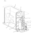
- Fig. 1 is a perspective view of an inside of the outdoor unit according to the present invention.
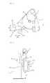
- Fig. 2 is a drawing showing in detail a construction related to the compressor and the absorption pipe connected to the compressor in Fig. 1;
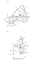
- Fig. 3 is a plan view of a construction related to the compressor and the absorption pipe connected to the compressor in Fig. 1;
- Fig. 4 is a side view of a construction related to the compressor and the absorption pipe connected to the compressor in Fig. 1;
- Fig. 5 is a drawing explaining a delivering state of rotational vibration of the compressor.
- Fig. 6 is a drawing explaining a delivering state of a right-left translational vibration of the compressor.
- Fig. 1 is a perspective view of an inside of the outdoor unit according to the present invention.
- the outdoor unit of the present invention includes for its inner construction: a compressor 1 for compressing a refrigerant; an outdoor heat exchanger 2 for exchanging heat of a refrigerant flowing in the inside; an outdoor fan 3 for forcibly sending an air to the outdoor heat exchanger 2; a four-way valve 7 for switching a flowing direction of a refrigerant; an absorption pipe 11 for connecting the compressor 1 with the four-way valve 7 so that a refrigerant may be absorbed into the compressor 1; a discharging pipe 12 for discharging a refrigerant compressed by the compressor 1; an indoor-connection pipe 13 for connecting the four -way valve 7 with the indoor unit; an outdoor-connection pipe 14 for connecting the four-way valve 7 with the outdoor heat exchanger 2; and concentrated mass 16 for reducing vibration of the absorption pipe 11. Also, on the part where the indoor - connection pipe 13 is projected, in its end, to the outside of the outdoor unit, a service valve 15 is formed.
- the absorption pipe 11 is projected approximately on the upper side of the compressor 1, extended toward the lower side of the compressor, and bent toward the upper side again, to be formed in an upward-rising shape.
- the absorption pipe 11 is looped approximately at the up and down parts of the compressor in this mann er, and the absorption pipe 11 of more than a predetermined length can be obtained.
- the absorption pipe 11 looped in the up -down direction, delivering force generated at the compressor and transferred by way of the absorption pipe 11 can be properly reduced.
- the present invention suggests the absorption pipe of a proper shape and length, capable of suppressing superposition/interference of vibration at the absorption pipe 11 and resonance occurring at the absorption pipe 11 due to vibration of the compressor, transferred to the absorption pipe 11.
- Fig. 2 is a drawing showing in detail a construction related to the compressor and the absorption pipe connected to the compressor in Fig. 1
- Fig. 3 is a plan view of a construction related to the compressor and the absorption pipe connected to the compressor
- Fig. 4 is a side view of a construction related to the compressor and the absorption pipe connected to the compressor.
- a compressor 1 for guiding a refrigerant into the inside of the compressor 1; an absorption pipe 11 for connecting the absorption port 4 with the four-way valve 7 so that a refrigerant may be absorbed into the inside of the compressor 1; a discharging pipe 12 for discharging the compressed refrigerant from the compressor 11 to the four -way valve 7, are provided. Also, for a vibration reducing member formed on a predetermined position of the absorption pipe 11, for reducing vibration of the absorption pipe 11, concentrated mas s 16 is provided.
- the absorption pipe 11 includes: a first straight pipe part 111 connected with the absorption port 4 on the whole and extended straight-upward direction; an upper curved part 112 bent toward the lower side from an end of the straig ht pipe part 111; a second straight pipe part 113 extended to the lower side from the upper curved part 112; a lower curved part 114 bent again toward the upper side from a lower end of the second straight pipe part 113; and a third straight pipe part 115 extended to the upper side from the lower curved part 114.
- One end of the third straight pipe part 115 is connected with the four-way valve 7 so that a refrigerant may flow inside the conduit line.
- the lower curved part 114 is looped in other direction different from the direction of the upper curved part 112, e.g., in a direction perpendicular to the direction of the upper curved part 112 , so that vibration may be counterbalanced.
- the present invention suggests a length L1 of the first straight pipe part 111, a diameter D2 of the upper curved part 112, a diameter D3 of the lower curved part 114.
- the present invention suggests correlation between the lowest height L3 of the absorption pipe 11 and the whole height of the compressor.
- the length L1 of the first straight pipe part 111 is limited below four times the diameter D1 of the absorption pipe. If the length of the first straight pipe part 111 is excessively long, vibration cannot be attenuated. Also, if the length of the first straight pipe part 111 is less than the diameter D1 of the absorption pipe, a process for connecting the absorption pipe 11 is difficult, which is not desirable.
- the diameter D2 of the upper curved part 112 is limited below three times the diameter D1 of the absorption pipe. If the diameter D2 of the upper curved part 112 is too big, since a distance between the compressor 1 and the end of the upper curved part 112 gets too long, rotational vibration of the compressor 1 is transferred to the absorption pipe 11 too much, therefore, the possibility that vibration is amplified gets increased as much as that, and the upper curved part 112 moves as a rigid body, whereby vibration reduction effect may become reduced. On the contrary, if the diameter D2 of the upper curved part 112 is limited below the diameter D1 of the absorption pipe, a flow of a refrigerant flowing inside the conduit line of the absorption pipe is not swift, which is not desirable.
- the lower end of the lower curved part 114 is positioned at th e height of more than one third of the whole height of the compressor.
- the height L3 of the lower end of the lower curved part 114 is positioned at the height of more than a predetermined level, the whole length of the second straight pipe part 113 is limited below a predetermined level.
- the reason why the length of the second straight pipe part 113 is limited is that if the length of the second straight pipe part 113 is long, vibration originating from right-left translational motion of the compressor 1 is transferred even much more and amplified, which is not desirable.
- the height L3 of the lower end of the lower curved part 114 is positioned at the position of more than three fourth of the compressor, the place at which the concentrated mass 16 is installed cannot be obtained, delivering force of the compressor is directly transferred to the four -way valve 7, and vibration of the outdoor unit itself gets big, which is not undesirable.
- the diameter D3 of the lower curved part 114 is limited below three times the diameter D1 of the absorption pipe. If the diameter D3 of the lower curved part 114 is too big, the lower curved part 114 moves as a rigid body, whereby vibration attenuation effect which can be obtained at the looped portion may not be obtained. Also, if the diameter D3 of the lower curved part 114 is limited below the diameter D of the absorption pipe, a flow of a refrigerant flowing inside the conduit line of the absorption pipe is not swift, which is not desirable.
- Fig. 5 is a drawing explaining a delivering state of rotational vibration of the compressor.
- Fig. 6 is a drawing explaining a delivering state of a right-left translational vibration of the compressor.
- the above -described absorption structure of the compressor is applied not only to the outdoor unit of the heat hump, which is the general cooling/heating system, but also to an outdoor unit of an air conditioner for cooling operation, an outdoor unit of a multi-type air conditioner, and an outdoor unit of an air conditioner having an accumulator as well.
- the absorption pipe structure of the outdoor unit in the air conditioner according to the sprit of the present invention can reduce vibration concentrated on the conventional absorption pipe, by designing the looping length of the absorption pipe short as much as possible within the range where compressor vibration suppression effect is maximized. Also, the present invention can reduce resonance that might occur at the absorption pipe and noise due to displacement.
Landscapes
- Engineering & Computer Science (AREA)
- Physics & Mathematics (AREA)
- General Engineering & Computer Science (AREA)
- Thermal Sciences (AREA)
- Mechanical Engineering (AREA)
- Life Sciences & Earth Sciences (AREA)
- Chemical & Material Sciences (AREA)
- Polymers & Plastics (AREA)
- Food Science & Technology (AREA)
- Health & Medical Sciences (AREA)
- Nutrition Science (AREA)
- Agronomy & Crop Science (AREA)
- Botany (AREA)
- Compressor (AREA)
- Other Air-Conditioning Systems (AREA)
Applications Claiming Priority (2)
| Application Number | Priority Date | Filing Date | Title |
|---|---|---|---|
| KR2004010077 | 2004-02-16 | ||
| KR1020040010077A KR100593084B1 (ko) | 2004-02-16 | 2004-02-16 | 에어컨 실외기의 흡입관 구조 |
Publications (2)
| Publication Number | Publication Date |
|---|---|
| EP1564508A2 true EP1564508A2 (de) | 2005-08-17 |
| EP1564508A3 EP1564508A3 (de) | 2011-07-06 |
Family
ID=34698992
Family Applications (1)
| Application Number | Title | Priority Date | Filing Date |
|---|---|---|---|
| EP05100892A Withdrawn EP1564508A3 (de) | 2004-02-16 | 2005-02-09 | Struktur eines Saugrohres eines Verdichters |
Country Status (5)
| Country | Link |
|---|---|
| US (1) | US7124599B2 (de) |
| EP (1) | EP1564508A3 (de) |
| JP (1) | JP2005233179A (de) |
| KR (1) | KR100593084B1 (de) |
| CN (1) | CN100427762C (de) |
Families Citing this family (15)
| Publication number | Priority date | Publication date | Assignee | Title |
|---|---|---|---|---|
| WO2009111024A2 (en) * | 2008-03-06 | 2009-09-11 | Carrier Corporation | Split discharge line with integrated muffler for a compressor |
| KR101721870B1 (ko) * | 2009-08-25 | 2017-03-31 | 엘지전자 주식회사 | 냉장고 |
| JP5575458B2 (ja) * | 2009-11-13 | 2014-08-20 | 日置電機株式会社 | 電気特性測定装置および電気特性測定方法 |
| CN102313405A (zh) * | 2010-07-08 | 2012-01-11 | 无锡松下冷机有限公司 | 冰箱 |
| CN103629867B (zh) * | 2012-08-20 | 2015-12-02 | 美的集团股份有限公司 | 一种压缩机配管系统及制冷装置 |
| CN104501379B (zh) * | 2014-12-19 | 2019-03-26 | 珠海格力电器股份有限公司 | 吸气配管管路、吸气结构、家用电器及除湿机 |
| CN105841409A (zh) * | 2016-03-21 | 2016-08-10 | 珠海格力电器股份有限公司 | 冷媒循环系统及具有其的空调器 |
| CN106121965B (zh) * | 2016-06-22 | 2019-02-12 | 青岛海信日立空调系统有限公司 | 压缩机吸气管路组件及空调室外机 |
| WO2019112307A1 (en) | 2017-12-05 | 2019-06-13 | Samsung Electronics Co., Ltd. | Air conditioner |
| JP6964526B2 (ja) * | 2018-01-17 | 2021-11-10 | 東芝キヤリア株式会社 | 熱源装置 |
| US11067299B2 (en) * | 2018-03-01 | 2021-07-20 | Haier Us Appliance Solutions, Inc. | Packaged terminal air conditioner unit with an inlet conduit hooked around an outlet conduit |
| CN109237637A (zh) * | 2018-09-25 | 2019-01-18 | 浙江佳中智能家居科技有限公司 | 一种输送冷媒的外机内压缩机所在腔室架构 |
| CN111648964A (zh) * | 2020-06-12 | 2020-09-11 | 四川长虹空调有限公司 | 用于空调压缩机的吸气管路结构 |
| CN112727735B (zh) * | 2020-12-28 | 2025-02-07 | 珠海格力电器股份有限公司 | 吸气管组件、双转子压缩机系统、空调器 |
| CN119393931B (zh) * | 2024-11-22 | 2025-12-09 | 深圳市英维克科技股份有限公司 | 管路系统 |
Family Cites Families (18)
| Publication number | Priority date | Publication date | Assignee | Title |
|---|---|---|---|---|
| GB927640A (en) * | 1960-02-11 | 1963-05-29 | Wilhelm Sydow Everett | A device for attenuating noises in fluid flow |
| JPS60117729A (ja) * | 1983-11-30 | 1985-06-25 | Canon Hanbai Kk | ノズルの位置合わせ装置 |
| JPS62127470A (ja) * | 1985-11-27 | 1987-06-09 | Hitachi Ltd | 薄膜形成装置 |
| IT1231284B (it) * | 1989-07-18 | 1991-11-28 | Delchi Carrier Spa | Apparecchiatura per il condizionamento dell'aria, a duplice possibilita' di funzionamento. |
| USH1317H (en) * | 1990-10-03 | 1994-06-07 | The United States Of America As Represented By The Secretary Of The Navy | Ring damper for structureborne noise suppression in piping systems |
| JPH0662676A (ja) * | 1992-08-11 | 1994-03-08 | Kureha Plast Kk | 人工ヘゴ材 |
| JPH0910673A (ja) * | 1995-04-27 | 1997-01-14 | Mitsubishi Heavy Ind Ltd | ダンピング構造体及びダンピング被膜形成方法 |
| JPH0953761A (ja) * | 1995-08-09 | 1997-02-25 | Calsonic Corp | 振動低減配管 |
| JPH0953759A (ja) * | 1995-08-09 | 1997-02-25 | Calsonic Corp | 振動低減配管 |
| JPH0953760A (ja) * | 1995-08-09 | 1997-02-25 | Calsonic Corp | 振動低減配管 |
| CN1143093C (zh) * | 1995-09-14 | 2004-03-24 | 大金工业株式会社 | 具有高热交换能力的空调机的紧凑式室外装置 |
| JPH09152232A (ja) * | 1995-09-27 | 1997-06-10 | Mitsubishi Electric Corp | 空気調和機用冷媒配管及びその製造方法 |
| JP2000145635A (ja) * | 1998-11-11 | 2000-05-26 | Toshiba Corp | 冷凍機の防振装置 |
| JP2000161817A (ja) * | 1998-11-24 | 2000-06-16 | Funai Electric Co Ltd | 圧縮機用配管の振動減衰装置 |
| JP2001214864A (ja) * | 2000-02-02 | 2001-08-10 | Sanyo Electric Co Ltd | 冷凍装置 |
| US6260373B1 (en) * | 2000-02-16 | 2001-07-17 | American Standard International Inc. | Heat exchanger with double vibration isolation |
| JP3711064B2 (ja) * | 2001-11-09 | 2005-10-26 | 三洋電機株式会社 | 空気調和装置 |
| JP2004324982A (ja) * | 2003-04-24 | 2004-11-18 | Matsushita Electric Ind Co Ltd | 空気調和機 |
-
2004
- 2004-02-16 KR KR1020040010077A patent/KR100593084B1/ko not_active Expired - Fee Related
- 2004-09-17 US US10/943,104 patent/US7124599B2/en not_active Expired - Fee Related
- 2004-10-12 CN CNB2004100850869A patent/CN100427762C/zh not_active Expired - Fee Related
-
2005
- 2005-01-17 JP JP2005008964A patent/JP2005233179A/ja active Pending
- 2005-02-09 EP EP05100892A patent/EP1564508A3/de not_active Withdrawn
Also Published As
| Publication number | Publication date |
|---|---|
| JP2005233179A (ja) | 2005-09-02 |
| US20050178140A1 (en) | 2005-08-18 |
| KR20050081714A (ko) | 2005-08-19 |
| CN1657782A (zh) | 2005-08-24 |
| EP1564508A3 (de) | 2011-07-06 |
| KR100593084B1 (ko) | 2006-06-26 |
| US7124599B2 (en) | 2006-10-24 |
| CN100427762C (zh) | 2008-10-22 |
Similar Documents
| Publication | Publication Date | Title |
|---|---|---|
| EP1564508A2 (de) | Struktur eines Saugrohres eines Verdichters | |
| US7121106B2 (en) | Pipe structure for outdoor unit of air conditioner | |
| EP1568954A2 (de) | Rohranordnung einer Ausseneinheit in einer Klimaanlage | |
| JP2005106367A (ja) | 空調室外機、空気調和機、及び圧縮機ユニット | |
| JP5217945B2 (ja) | 冷凍サイクル装置 | |
| US7111475B2 (en) | Pipe structure of air conditioner | |
| JP7199335B2 (ja) | 電動弁及び冷凍サイクルシステム | |
| US20050235690A1 (en) | Outdoor unit of air conditioning system | |
| CN110056982A (zh) | 空调室外机及其配管组件 | |
| JPWO2008102815A1 (ja) | 分岐管装置 | |
| CA2614318A1 (en) | Variable fin density coil | |
| KR100758910B1 (ko) | 공기조화기의 실외기 | |
| JP2004324982A (ja) | 空気調和機 | |
| KR102842814B1 (ko) | 차량용 에어컨 배관 | |
| CN219589076U (zh) | 空调器室外机 | |
| JPH0243017Y2 (de) | ||
| KR100412859B1 (ko) | 에어컨 컴프레서용 머플러 | |
| CN220583155U (zh) | 换热装置及冰箱 | |
| KR20030050932A (ko) | 공기조화기의 방진장치 | |
| US20190170374A1 (en) | Air conditioner | |
| CN220204089U (zh) | 排气管消音结构、压缩机、空调 | |
| CN210861788U (zh) | 用于换热系统的换向装置和换热系统 | |
| KR102233359B1 (ko) | 냉매 배관 시스템 | |
| KR100648948B1 (ko) | 공기조화기의 파이프 방진장치 | |
| KR100774002B1 (ko) | 배관용 진동 저감부재 |
Legal Events
| Date | Code | Title | Description |
|---|---|---|---|
| PUAI | Public reference made under article 153(3) epc to a published international application that has entered the european phase |
Free format text: ORIGINAL CODE: 0009012 |
|
| AK | Designated contracting states |
Kind code of ref document: A2 Designated state(s): AT BE BG CH CY CZ DE DK EE ES FI FR GB GR HU IE IS IT LI LT LU MC NL PL PT RO SE SI SK TR |
|
| AX | Request for extension of the european patent |
Extension state: AL BA HR LV MK YU |
|
| PUAL | Search report despatched |
Free format text: ORIGINAL CODE: 0009013 |
|
| AK | Designated contracting states |
Kind code of ref document: A3 Designated state(s): AT BE BG CH CY CZ DE DK EE ES FI FR GB GR HU IE IS IT LI LT LU MC NL PL PT RO SE SI SK TR |
|
| AX | Request for extension of the european patent |
Extension state: AL BA HR LV MK YU |
|
| RIC1 | Information provided on ipc code assigned before grant |
Ipc: F25B 31/00 20060101ALI20110629BHEP Ipc: F25B 41/00 20060101AFI20110629BHEP |
|
| AKY | No designation fees paid | ||
| REG | Reference to a national code |
Ref country code: DE Ref legal event code: R108 Effective date: 20120314 |
|
| STAA | Information on the status of an ep patent application or granted ep patent |
Free format text: STATUS: THE APPLICATION IS DEEMED TO BE WITHDRAWN |
|
| 18D | Application deemed to be withdrawn |
Effective date: 20120110 |