EP1555812B1 - Bildaufnahmevorrichtung und -verfahren - Google Patents
Bildaufnahmevorrichtung und -verfahren Download PDFInfo
- Publication number
- EP1555812B1 EP1555812B1 EP05250180.6A EP05250180A EP1555812B1 EP 1555812 B1 EP1555812 B1 EP 1555812B1 EP 05250180 A EP05250180 A EP 05250180A EP 1555812 B1 EP1555812 B1 EP 1555812B1
- Authority
- EP
- European Patent Office
- Prior art keywords
- ranging
- light
- fill
- focus
- imaging apparatus
- Prior art date
- Legal status (The legal status is an assumption and is not a legal conclusion. Google has not performed a legal analysis and makes no representation as to the accuracy of the status listed.)
- Ceased
Links
- 238000003384 imaging method Methods 0.000 title claims description 41
- 230000007246 mechanism Effects 0.000 claims description 18
- 238000005259 measurement Methods 0.000 claims description 4
- 230000001419 dependent effect Effects 0.000 claims 1
- 230000001678 irradiating effect Effects 0.000 claims 1
- 238000000034 method Methods 0.000 description 104
- 230000008569 process Effects 0.000 description 74
- 230000001276 controlling effect Effects 0.000 description 30
- 238000012545 processing Methods 0.000 description 11
- 230000003287 optical effect Effects 0.000 description 10
- 230000000875 corresponding effect Effects 0.000 description 8
- 238000006243 chemical reaction Methods 0.000 description 6
- 230000010354 integration Effects 0.000 description 6
- 238000004891 communication Methods 0.000 description 4
- 230000006870 function Effects 0.000 description 4
- 230000000977 initiatory effect Effects 0.000 description 4
- 230000001360 synchronised effect Effects 0.000 description 4
- 238000001514 detection method Methods 0.000 description 3
- 230000004907 flux Effects 0.000 description 3
- 239000004973 liquid crystal related substance Substances 0.000 description 3
- 230000000694 effects Effects 0.000 description 2
- 238000011156 evaluation Methods 0.000 description 2
- 238000003825 pressing Methods 0.000 description 2
- GGCZERPQGJTIQP-UHFFFAOYSA-N sodium;9,10-dioxoanthracene-2-sulfonic acid Chemical compound [Na+].C1=CC=C2C(=O)C3=CC(S(=O)(=O)O)=CC=C3C(=O)C2=C1 GGCZERPQGJTIQP-UHFFFAOYSA-N 0.000 description 2
- 238000003491 array Methods 0.000 description 1
- 230000008859 change Effects 0.000 description 1
- 230000006835 compression Effects 0.000 description 1
- 238000007906 compression Methods 0.000 description 1
- 230000002596 correlated effect Effects 0.000 description 1
- 238000001914 filtration Methods 0.000 description 1
- 238000012544 monitoring process Methods 0.000 description 1
- 230000005855 radiation Effects 0.000 description 1
- 230000009467 reduction Effects 0.000 description 1
- 238000005070 sampling Methods 0.000 description 1
- 230000003068 static effect Effects 0.000 description 1
Images


Classifications
-
- H—ELECTRICITY
- H04—ELECTRIC COMMUNICATION TECHNIQUE
- H04N—PICTORIAL COMMUNICATION, e.g. TELEVISION
- H04N23/00—Cameras or camera modules comprising electronic image sensors; Control thereof
- H04N23/60—Control of cameras or camera modules
- H04N23/67—Focus control based on electronic image sensor signals
- H04N23/671—Focus control based on electronic image sensor signals in combination with active ranging signals, e.g. using light or sound signals emitted toward objects
-
- H—ELECTRICITY
- H04—ELECTRIC COMMUNICATION TECHNIQUE
- H04N—PICTORIAL COMMUNICATION, e.g. TELEVISION
- H04N23/00—Cameras or camera modules comprising electronic image sensors; Control thereof
- H04N23/70—Circuitry for compensating brightness variation in the scene
- H04N23/74—Circuitry for compensating brightness variation in the scene by influencing the scene brightness using illuminating means
-
- H—ELECTRICITY
- H04—ELECTRIC COMMUNICATION TECHNIQUE
- H04N—PICTORIAL COMMUNICATION, e.g. TELEVISION
- H04N2101/00—Still video cameras
Definitions
- the present invention relates to an imaging apparatus and an imaging method of a passive type applicable to an automatic focussing device being useable in a digital camera, a silver salt camera and the other types of camera.
- the structure includes a plurality of arrays of photoelectric conversion elements disposed vertically with respect to a pair of images of the subject, an image processing unit for preparing image information from the output of the photoelectric conversion elements, and an image deviation detecting part for detecting an amount of deviation between the same portions of the subject based in the right and left image information prepared as described above (for reference, see Japanese Patent Laid-Open No. H8-334681 ).
- a structure using a flash device as a source of fill-light during an auto focus process In the structure, if a camera controlling part determines, as a result of measurement of light by a light measuring part, that focus detection is not possible when the brightness of the subject or contrast is low then a built-in flash or external flash is operated, and the light is used as the fill-light for an auto-focus ranging (for reference, see Japanese Patent Laid-Open No. H5-34577 ).
- a sequence is taken that AF (ranging), display of an AF result, and focussing are executed on a half-press (first step), and exposure, namely, shutter control is executed on a full-press (second step).
- the fill-light is emitted simultaneously with an AF operation on the half-press of the release.
- the fill-light is emitted simultaneously with the AF operation in the half-press of the release, if a subject photographed is a person, there is a problem that the person misunderstands that the photograph has been taken when emitting the fill-light in the half-press. In particular, this tendency is higher in case of using the strobe as the fill-light. Because the fill-light is emitted every time the release is half-pressed in these cameras, there is a problem that an operating life of a battery becomes short and so on.
- an auto-focus camera disclosed in Japanese Utility Model Laid-Open No. H7-22648 as a conventional art for driving a photographic lens in a focussing position by measuring automatically a distance to a subject when operating a release or shutter
- an illuminating device for photograph disclosed in Japanese Patent Laid-Open No. 2002-207236 as a conventional art for adjusting an emitted amount of light according to a distance to a subject
- an auxiliary illuminating device for an auto-focusing camera disclosed in Japanese Patent No. 2691206 as a conventional art for carrying out a detection of focussing by radiation of light of the auxiliary illuminating device
- an auto-focussing camera disclosed in Japanese Patent No. 2709375 as a conventional auto-focussing camera having a flashing device projecting fill-light to a subject.
- US 2001/0038751 A1 discloses a focus detecting device in which the object of focus detection is illuminated with auxiliary light if the luminance of the object is low.
- the camera has a two position shutter switch and autofocus including use of an auxiliary light is initiated when the shutter switch is in a half-pressed position.
- the present invention has been made in view of the above problems in the prior art as described above.
- An aim of the present invention is to provide an imaging device in which if fill-light is emitted simultaneously with an AF operation when half-pressing a release, a person who is photographed is not lead to misunderstand that the photograph has been taken when the fill-light is emitted, and a battery has a long operating life.
- An imaging apparatus comprises a photographic operating device having two operational positions, including at least a half-pressed position and a full-pressed position, a ranging device for measuring a distance to a subject, a fill-light radiating device for radiating fill light to the subject, a focus-adjustment controlling device for controlling adjustment of a focus based on a measured result of the ranging device, an exposure controlling device for controlling an exposure, and a fill-light determining device for determining whether the fill light is required.
- the focus-adjustment controlling device does not adjust the focussing.
- the fill-light radiating device radiates the fill light to the subject and the re-ranging is achieved by means of the ranging device.
- the focus-adjustment controlling device computes a focus adjusting position based on a result of the re-ranging, and the exposure is achieved by means of the exposure-controlling device after the focus adjustment is controlled by means of the focus-adjustment controlling device based on the focus adjusting position.
- FIG. 1 An embodiment in which the imaging apparatus according to the present invention is applied to a digital camera is illustrated in FIG. 1 .
- the digital camera is provided at an upper surface thereof with a release shutter or release button SW1, a mode dial SW2 and a sub liquid crystal display (sub LCD) 1, as shown in FIGs.1 to 3 .
- a release shutter or release button SW1 a release shutter or release button
- a mode dial SW2 a mode dial
- sub LCD sub liquid crystal display
- the digital camera is also provided at a front surface thereof with a cover 2 for a storage for containing a memory card, for example, an SD type card and a power battery, a strobe-light emitting part 3, an optical find 4, a ranging device 5, which will be described hereinafter, a remote controlling light-receiving part 6 and a lens barrel unit 7, as shown in FIG.1 .
- a memory card for example, an SD type card and a power battery
- a strobe-light emitting part 3 an optical find 4
- a ranging device 5 which will be described hereinafter
- a remote controlling light-receiving part 6 and a lens barrel unit 7, as shown in FIG.1 .
- the digital camera is further provided at a rear surface thereof with an AF (auto focus) and LED (light emitting diode) 8 for radiating a light beam toward the subject to adjust a auto-focusing, a strobe-LED 9 to display an operation of strobe, a monitor, for example, an LCD monitor 10 comprising a liquid crystal display, a zoom switch (wide) SW3, a zoom switch (far and near) SW4, a self timer/deleting switch SW 5 and a menu switch SW6, as shown in FIG.3 .
- AF auto focus
- LED light emitting diode
- an upper strobe switch SW7, a right switch SW8, a display switch SW9, a lower/micro switch SW10, a left-image confirming switch 11, an OK switch SW12, and a power switch SW13 are disposed on the rear surface of the digital camera.
- the digital camera comprises the above-mentioned ranging device 5 for measuring a distance to a subject S, as shown in FIGs.12 and 13 , a device for radiating fill light to the subject, and a re-ranging determining device for determining as to whether re-measurement is executed based on a measured result of the ranging device 5.
- the ranging device 5, the fill-light radiating device and the re-ranging determining device are controlled mutually by means of a CPU (not shown) installed in the digital camera. This control will be described in detail hereinafter.
- the ranging device 5 is referred to as a ranging unit or an exterior AT unit in the specification.
- the fill-light radiating device includes the above-mentioned strobe-light emitting part 3, an LED, a lamp or the like in an embodiment.
- the re-ranging determining device includes a program installed in the CPU.
- the ranging device 5 generally comprises right and left lenses 14, aperture stops 15 disposed corresponding to each of the lenses 14, and a ranging element mechanism 16, which measures a distance to the subject by imaging a light flux from the subject, as shown in FIGs12 and 13 .
- the ranging device 5 also includes a ranging arithmetical mechanism for computing a ranging based on outputting data of the ranging element mechanism 16, an area selecting mechanism for selecting an area based on an arithmetical result of the ranging arithmetical mechanism.
- the ranging element mechanism 16 has at least a pair of right and left light receiving sensors 17a and 17b for receiving light from the subject S, each of which has a plurality of light receiving areas 18 arranged in line.
- Each of the plurality of light receiving areas 18 is a charge storage-type capable of imaging the light flux from the subject S (see FIG. 14 ).
- Each light receiving area has a plurality of light receiving elements, which will be described hereinafter.
- the ranging element mechanism 16 includes a program to control reading out of the charge storage or an amount of received light of each light receiving sensor.
- the ranging arithmetical mechanism and the area selecting mechanism include programs in the CPU.
- the lenses 14 allow light from the subject to image on the light receiving sensors 17a and 17b, and the aperture stops 15 limit an amount of light entering into the light receiving sensors.
- the right light receiving sensor 17a and the left light receiving sensor 17b have first to sixth light receiving areas 19a to 19f, respectively, in an embodiment shown in FIG.14 .
- A denotes a distance between the right and left light receiving sensors, in FIG.14; and B a distance between the areas in the right and left light receiving sensors, respectively, in FIGs.13 and 14 .
- FIG. 15A illustrates light receiving data C of the right light receiving sensor 17a
- FIG.15B illustrates light receiving data D of the left light receiving sensor 17b
- a vertical axis shows a magnitude of the light receiving data
- a horizontal axis shows a position of each light receiving element in each light receiving area.
- E denotes a deviation, X1 + X2 of the light receiving data between the right and left light receiving sensors.
- FIG.16A illustrates a determined value G of contrast to determine whether a difference between the maximum and minimum values of the light receiving data is more than a rated value
- FIG.16B illustrates values of right and left images, in which H denotes light receiving data of the right sensor 17a, and I denotes light receiving data of the left sensor 17b.
- a vertical axis shows a magnitude of the light receiving data
- a horizontal axis shows a position of each of the light receiving elements within the light receiving areas.
- the distance L from a central position perpendicular to an optical axis of each of the lenses 14 to the subject is computed by the following formula based on a triangular ranging method.
- L B ⁇ f / X ⁇ 1 + X ⁇ 2
- the distance L to the subject can be computed by use of the above-mentioned formula by reading out the light receiving amount of the light receiving sensors and the (X1 + X2) by the CPU, respectively.
- the light receiving sensors 17a and 17b have a plurality of light receiving elements, which have mutually equal numbers.
- One light receiving area is formed by including a predetermined number of light receiving elements, and the right and left light receiving sensors have the plurality of light receiving areas as described above.
- the light receiving elements included in each light receiving area may be overlapped with that in the other light receiving areas.
- the right and left light receiving sensors are composed of the one hundred thirty (130) light receiving elements, respectively.
- a light receiving area No.1 comprises the light receiving elements of first to thirtieth from the left end of the sensors
- a light receiving area No.2 comprises the light receiving elements of twentieth to fiftieth
- a light receiving area No.3 comprises the light receiving elements of fortieth to seventieth
- a light receiving area No.4 comprises the light receiving elements of sixtieth to ninetieth
- a light receiving area No,5 comprises the light receiving elements of eightieth to one hundred tenth
- a light receiving area No.6 comprises the light receiving elements of ninetieth to one hundred thirtieth.
- the ten light receiving elements from the left end of each light receiving area are overlapped with the others
- the (X1 + X2) is obtained by detecting how shapes of the light receiving data deviate, comparing the shapes of the light receiving data of the right and left corresponding light receiving areas, as shown in FIGs. 15A and 15B .
- a contrast determination is judged as NG. Whether both the corresponding right and left light receiving areas are more than the rated value are judged.
- the receiving data of the right and left light receiving areas should be ideally the same shape in a direction of the vertical axis. However, there is a case that the shape is different in the direction of the vertical axis as a condition of light in the subject. Therefore, the determination of a difference between right and left images is executed by comparing the sum of the amount of light that all the light receiving elements in the light receiving areas receive, in the right and left light receiving sensors.
- An area surrounded by a straight line H showing the sum of the amount of light received in the right light receiving sensor in FIG.16B , and a broken line I showing the sum of the amount of light received in the left light receiving sensor shows a difference of the sum of the amount of light received in the right and left light receiving sensors. If this value is more than a predetermined value, determination of the difference between the right and left images is NG.
- the fill-light radiating device is configured to radiate the fill light to the subject.
- the camera comprises a photographic operating device including two-step operational positions having at least a half pressed position and a full-pressed position, a ranging device for measuring a distance to a subject, a fill-light radiating device for radiating fill light to the subject, a focus-adjustment controlling device for controlling adjustment of a focus based on a measured result of the ranging device, an exposure controlling device for controlling an exposure, and a fill-light determining device for determining whether the fill light is required.
- the photographic operating device includes a release shutter SW1 in the embodiment.
- the ranging device and the fill-light radiating device in the embodiment are the same as described above, in structure.
- the focus-adjustment controlling device for adjusting the focusing, the exposure controlling device and the fill-light determining device include programs installed in the CPU in the embodiment. Moreover, the devices as described above are mutually controlled by means of the CPU. A detail thereof will be described hereinafter.
- the focus-adjustment controlling device when the photographic operating device is in the half-pressed position and the fill-light determining device determines that the fill light is required, the focus-adjustment controlling device does not adjust the focusing.
- the fill-light radiating device radiates the fill light to the subject, the re-ranging is achieved by the ranging device, and the focus-adjustment controlling device computes a focus adjusting position based on a result of the re-ranging, and the exposure is achieved by the exposure controlling device after the focus adjustment is controlled by the focus-adjustment controlling device based on the focus adjusting position.
- the digital camera also includes a reliable determining mechanism for determining reliability based on the measured result of the ranging device.
- the reliable determining mechanism includes a program in the CPU.
- the focus-adjustment controlling device has a mechanism for computing a focus adjusting position based on the measured result of the ranging device.
- the mechanism for computing the focus adjusting position is composed of a program in the CPU.
- a lens barrel unit 7 includes a zoom optical system 7-1 comprising a zoom lens 7-1a taking in an optical image of the subject and a zoom driving motor 7-1b, and a focus optical system 7-2 comprising a focus lens 7-2a and a focus driving motor 7-2b.
- the lens barrel unit 7 also includes an aperture stop unit 7-3 comprising an aperture stop 7-3a and an aperture stop motor 7-3b, a mechanical shutter unit 7-4 comprising a mechanical shutter 7-4a and a mechanical shutter motor 7-4b, and a motor driver 7-5 for driving each motor.
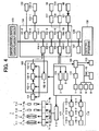
- the motor driver 7-5 is structured to control by a driving command from a CPU block 104-3 provided in a digital camera processor 104 which will be described hereinafter, based on an operational signal in which light received by a remote control light receiving part 6 is converted into an electrical signal, or an operational signal input in accordance with the operation of operating key units SW1 to SW13.
- the zoom optical system 7-1 and the focus optical system 7-2 correspond to the aforementioned lenses 14, the aperture stop unit 7-3 corresponds to the above-mentioned aperture stop 15, and the operating key units SW1 to SW 13 correspond to the photographic operating device.
- a controlling program and controlling parameters, which are written by readable codes in a CPU block 104-1 or CCD 1-signal processing block are stored in a Read Only Memory (hereinafter referred to as ROM) shown at 108 in FIG.4 .
- ROM Read Only Memory
- the controlling program is loaded on a main memory (not shown), and the CPU block 104-1 controls operations of parts in the imaging apparatus in accordance with the programs thereof.
- Data and so on necessary to the control are stored temporarily in a local SRAM (static RAM) 104-4 provided in each of a Random Access Memory (hereinafter referred to as RAM) 107 and a digital still camera processor 104.
- the SRAM means a RAM in which a holding operation is not required.
- re-writable flush ROM is used as the ROM 108, it is possible to change the controlling programs and the controlling parameters, there is an advantageous effect that version up of the functions is accomplished easily.
- the ranging element mechanism 16 concretely includes a CCD (charge coupled device) 101, which comprise charge-storage type solid-state image sensors for conducting the optical image-photography conversion, an image signal which is imaged and converted into the electrical signal is adapted to input into an F/E (front-end)-IC 102.
- the F/E-IC 102 has a CDS 1021 for conducting a correlating double sampling for removing a noise of the image, an AGC (automatic gain control) 102-2 for conducting gain adjustment, and an A/D 102-3 for conducting a digital signal conversion.
- the F/E-IC 102 also includes a timing generator (hereinafter referred to as TG) 102-4, to which a vertical synchronous signal (hereinafter referred to as VD) and a horizontal synchronous signal (hereinafter referred to as HD) is supplied from the CPU block 104-1 included in the processor 104, and which generates a driving timing signal for the CCD 101 and the F/E-IC 102 controlled by a CPU block 104-3.
- TG timing generator
- VD vertical synchronous signal
- HD horizontal synchronous signal
- the digital still camera processor 104 executes a balance setting or gamma setting from the CCD 101 to output data of the F/ E-IC 102, and has the CCD-signal processing block 104-1 for supplying the VD and HD signals.
- the processor 104-1 further includes a CCD 2-signal processing block 104-2 for conducting the conversion to brightness data and color different data by a filtering processing.
- the processor 104 has the CPU block 104-3 for conducting the operation of each part of the imaging apparatus, the local SRAM 104-4 for storing temporarily the data and so on required to the control, as described above, a USB block 104-5 for conducting communication with an exterior instrument such as a personal computer (hereinafter referred to as PC), and a serial block 104-6 for conducting serial communication with the PC and so on.
- PC personal computer
- the above-mentioned processor 104 includes a JPEG and CODEC block 104-7 for conducting compression and extension of a JPEG (joint photographic experts group), a re-size block 104-8 for conducting enlargement and reduction of a size of the image data by an interpolating process, a TV signal displaying block 104-9 for converting into a video signal to display the image data on an exterior display instrument such as a liquid crystal monitor, a TV or the like, and a memory card block 104-10 for conducting control of a memory card recording photographed image data.
- JPEG and CODEC block 104-7 for conducting compression and extension of a JPEG (joint photographic experts group)
- a re-size block 104-8 for conducting enlargement and reduction of a size of the image data by an interpolating process
- a TV signal displaying block 104-9 for converting into a video signal to display the image data on an exterior display instrument such as a liquid crystal monitor, a TV or the like
- the SDRAM 103 stores temporarily the image data when various processes are executed by means of the processor 104 based on the image data.
- the stored image data are introduced through the F/E-IC 102 from the CCD 101, as one example, it is "RAM-RGB image data" in which white balance and gamma settings are executed by the CCD 1-signal processing block 104-1.
- Another example of the introduced data is "YUV image data” in which the brightness data/the color difference conversion is executed by the CCD 2-signal processing block 104-2, or "JPEG image data” compressed by the JPEG and CODEC block 104-7.
- a memory card slot 121 is for inserting therein an attachable memory card 40.
- a built-in memory 120 is for storing the photographed image data even if the memory card 40 is not inserted in the memory card slot 121.
- An LCD driver 117 is a driver circuit for driving the LCD monitor 10 which will be described hereinafter in detail, and has a function for converting the video signal output from the TV signal displaying block 104-9 into a signal for displaying on the LCD monitor 10.
- the LCD monitor 10 is one to use for various objects that monitors a state of the subject before photographing, confirms the photographed image, and displays the image data recorded in the memory card 40 and the built-in memory 120.
- a video AMF 118 is an amplifier for converting the video signal output from the TV signal displaying block 104-9 included in the processor 104 into impedance of 75 ⁇
- a video jack 119 is for connecting with an exterior displaying instrument such as a TV.
- a USB connector 122 is for conducting a USE connection with an exterior instrument such as a personal computer and so on.
- a serial driver circuit 123-1 is a circuit for converting an output signal from the serial block into a voltage in order to conduct a serial communication with an external instrument such as a personal computer.
- An RS-232C connector 123-2 is for conducting a serial communication with an external instrument such as a personal computer and so on.
- a sub CPU 109 is a CPU in which a ROM and RAM is loaded in one chip and which outputs a signal from the above-mentioned operating key units SW1 to SW13 or the remote controlling light-receiving part 6 to the CPU block 104-3 as operational information for a user, or outputs a state of the camera output from the CPU block 104-3 by converting the state into a control signal of the sub LCD 1, the AF and LCD 8, the strobe-LED 9 and a buzzer 27, which will be described hereinafter.
- the sub LCD 1 is a displaying part for displaying, for example, photograph possible numbers and so on, an LCD driver 111 is a driving circuit for driving the sub LCD 1 based on the output signal from the sub CPU 109.
- the AF and LED 8 is an LED for displaying a focused state when photographing
- the strobe-LED 9 is an LED for displaying a charged state of a main condenser in the strobe.
- the AF and LED 8, and the strobe-LED 9 may be employed for the other displaying use such as memory card access and so on.
- the operating key units SW1 to SW13 include a key circuit operated by the user, and the remote controlling light-receiving part 6 includes a receiving part for a signal of a remote controlling transmitter operated by the user.
- a voice recording unit 115 comprises a microphone 115-3 in which the user inputs a voice signal, a microphone amplifier 115-2 for amplifying the input voice signal, and a voice recording circuit 115-1 for recording the amplified voice signal.
- a voice playing-back unit 116 comprises a voice playing-back circuit 116-1 for converting the recorded voice signal into a signal capable of outputting from a speaker 116-3 which will be described hereinafter, an audio AMP 116-2 for amplifying the converted voice signal and driving the speaker, and the speaker 116-3 for outputting the voice signal.
- the ranging method has two modes including a first mode in which the release button SW1 is executed in the half pressed position (method of performing the re-ranging before photographing), and a second mode in which the release button SW1 is executed in the full-pressed position (method of performing the re-ranging when photographing).
- the camera When the release is in the half-pressed position, the camera initiates a focusing.
- a command in which light is received is output from the digital still camera processor 104 to the exterior AF unit 5 ( FIG.2 ) by which a measured result is output.
- the focus optical system 7-2 is moved to a focus position corresponding to a distance to the subject, which is obtained based on the measured result. Because the embodiment according to the present invention relates to the light reception and the method of computing the ranging in the exterior AF unit 5, the exterior AF unit 5 and methods for computing the re-ranging and for determining the re-ranging by use of the exterior AF unit 5 will be explained.
- the exterior AF unit 5 contains charge-storage type light receiving sensors arranged rightward and leftward in line, for example, CCD line sensors.
- the light receiving sensors have a plurality of light receiving areas, and right and left light receiving areas are disposed to correspond with respect to each other.
- a command of received light is transmitted from the exterior AT unit 5
- the right and left light receiving sensors receive light in accordance with a charge-storage mode, which is an operational mode of the exterior AF unit 5.
- the charge-storage mode determines a light receiving system of the light receiving sensors in the exterior AF unit 5 and has an automatic storage mode and a forcing storage mode.
- the automatic storage mode completes automatically if an amount of light, which is more than a fixed amount is detected even by one of the light receiving sensors. A lapsed time at this time is set as a charge-storage time.
- the charge storage mode is adapted to perform the light reception by an automatic integration mode.
- the light reception is completed, a correlation between the right and left images of the subject in each area of the light receiving sensors is detected, and a deviated amount between the right and left light receiving elements is calculated based on a correlated value detected as described above.
- a distance to the subject is calculated by use of a triangular surveying method based the deviated amount to set the calculated distance. Consequently, each area has a mutually different ranging value or ranging data.
- a ranging value output from the exterior AF unit 5 toward the camera and the area thereof are decided by determining whether the ranging value in each area is near the rated value than that of the other areas, in the other words, effectiveness of sensor data received in the area is higher.
- the determination of the effectiveness of the sensor data is accomplished by whether the contrast of the light receiving data in each area, the difference between the images in the right and left sensors, and so on satisfy the rated value. However, if all the areas do not satisfy the rated value, an area having the highest effectiveness of the ranging values in the entire areas, or area closest to the rated value is selected.
- a flow chart shown in FIG.5 shows the imaging method, in other words, the AF ranging method in which the structure and arithmetical method of the above-mentioned ranging apparatus or the exterior AF unit 5 are used.
- the ranging is accomplished by using the structure and the arithmetical method of the exterior AT unit 5, and the results of a re-ranging arithmetical process ( FIG.6 ) and a re-ranging determining process (FIG-7), in other words, deciding the charge-storage mode and turning on a strobe fill-light flag, which will be described hereinafter.
- FIG.5 steps of operation are shown as 5-1, 5 ⁇ 2 ⁇ , for example.
- the automatic storage mode is determined with respect to the light reception in the exterior AF unit (5-1). If so, the step is shifted to the next step (5-3). If not so, that is to say, if it is the automatic storage mode, the 5-1 step is shifted to the next step (5-3) through a process (5-2) for setting a charge-storage time.
- the setting of the charge-storage time is one set in the re-ranging determining process ( FIG.7 ) as described hereinafter.
- whether the strobe fill-light flag is ON is determined.
- the strobe fill-light flag is decided by setting ON/OFF of the strobe fill-light flag in the re-ranging determining process ( FIG.7 ) as described hereinafter. If the strobe fill-light flag is in ON, a process (5-4) preparing the strobe so as to capable of emitting the strobe when receiving light is executed, if not so, a light receptioin procsss is executed.
- the light flux of the subject is received in the charge-storage type light receiving elements by the light reception process (5-5).
- the strobe fill-light flag is ON as a result of the determination in the step (5-3)
- light emission is carried out through a predetermined light emitting time during the light reception.
- the predetermined light emitting time means a time necessary to obtain an amount of light emission that the strobe is capable of reaching to a degree of distance, for example, about 5 meters.
- the time is a fixed time, for example, 10 ⁇ s in the embodiment. However, because the setting of the light emitting time depends on performance of a strobe unit, the time may be changed.
- a ranging arithmetical process is executed to calculate a ranging value (5-6).
- the arithmetical method is as described in the explanation of the structure and the arithmetical method of the exterior AF unit 5.
- a ranging determining process (5-7) is configured to output as a ranging value a distance in an area considered to be the highest effectiveness of ranging values in the areas calculated in the previous process, and the area selected at the present time is also output (5-8).
- the above is an explanation regarding the exterior AF ranging method showing in FIG.5 .
- a first ranging is first started (6-1).
- the first ranging is executed along the flows of the AF ranging method shown in FIG.5 .
- the charge-storage mode is set to the automatic storage mode, and the strobe fill-light flag is executed in ON.
- the determination of effectiveness of the ranging value in the selected area is executed in the re-ranging determining process (6-2).
- the determination. of effectiveness is performed by the re-ranging determining process or device, which will be described hereinafter in FIG.7 .
- whether a re-ranging flag is ON is determined (6-3). If so, the process is shifted to a process (6-9) initiating a second ranging. If not so, a ranging value and area is selected by the first ranging (6-9).
- the second ranging is started.
- the second ranging is executed along the flows in the AF ranging as describe above, at this time, the charge-storage mode, if the strobe fill-light flag is ON, is adapted to perform with the automatic integration mode, if not so, with the forcing storage mode.
- the charge-storage time in the forcing storage mode corresponds to a forcing charge-storage time obtained in the re-ranging determining process ( FIG.7 ) as described hereinafter.
- a determination of the second ranging is executed based on a calculated result in the second ranging (6-5).
- the second ranging and area is selected to set that as a final output. If not so, the second ranging value is compared with the first ranging value and then one ranging value and area of these ranging values, more near the rated value is selected. More specifically, if the second ranging value is near the rated value, the second ranging value and area is selected (6-8), if not so, the first ranging and area is selected (6-9). Finally, the selected ranging and area is output as the final ranging value and area (6-10).
- the second ranging and area is selected to set that as a final output.
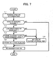
- FIG.7 is a flow chart showing a series of flows of the re-ranging determining process or device during the re-ranging arithmetic as described above.
- the determination or NG determination of effectiveness of the ranging result is first performed (7-1). In the process, whether the ranging value in the selected area is near the rated value than that in the other areas is first determined. If not so, if a difference between the ranging value in the selected area and the near ranging value is more than a fixed range, the re-ranging determining process determines that the re-ranging is required, and is shifted to the next process. If not so, the re-ranging determining process determines that the re-ranging is not required.
- the ranging value in the selected area is near the rated value than that in the other areas, but if the ranging value in the selected area has a lower effectiveness or NG in the ranging determining process in flows of the AF ranging, the re-ranging determining process determines that the re-ranging is required and proceeds to the next process, if not so, it determines that the re-ranging is not required (7-2).
- step (7-2) If the determination that the re-ranging is required is made in the above-mentioned step (7-2), whether the circumstance of the subject is a low brightness or backlight is determined (7-3). If so, the determination that the strobe fill-light is required is made and the 7-3 process is shifted to the next process. If not so, the 7-3 process is sifted to a process (7-6) for setting the charge-storage time.
- the determination as to whether the circumstance is the low brightness or backlight is made by a magnification of sensor data from each area of the ranging unit 5 or use of a measured result in calculating an appropriate exposure when monitoring using the imaging elements of the digital camera.
- the process (7-5) for setting the charge-storage time if the ranging value of the selected area is not near the rated value than that of the other areas, the area having the near ranging value at this time is set as an area setting the charge-swrage time, an optimum charge-storage time is set in the light receiving elements in this area.
- the selected area at this time is set to an area for setting the charge-storage time, an optimum charge-storage time is set in the light receiving elements in this area.
- the function for setting the charge-storage time includes searching the minimum of the charge-storage times in the light receiving elements in the area for setting the charge-storage time, the first ranging, obtaining a proportion of the minimum and the maximum of the charge-storage times in all the light receiving elements, and multiplying the first charge-storage time by the proportion to set that value as a forcing charge-storage time.
- the forcing charge-storage time is set by selecting the most large value among the minimum values, obtaining a proportion of the most large value and the maximum value in all the light receiving elements, and multiplying the first charge-storage time by the proportion.
- step (7-3) if the determination is made, which is in the circumstance of the subject that the strobe fill-light is required, whether the charging level of the strobe fill-light is a predetermined level, that is to say, the level is possible to radiate the fill light by a predetermined light emitting time is determined (7-4), if it is more than the predetermined level, the strobe fill-light flag is set to be ON (7-6). If not so, the determination that the strobe fill-light cannot be emitted is made and the present process is shifted to the process (7-5) for setting the charge-storage time.
- a predetermined level that is to say, the level is possible to radiate the fill light by a predetermined light emitting time
- the shift to the process for setting the charge-storage time is made, but the strobe is charged until the charging level is more than the predetermined level, thereafter a structure may be taken such that strobe fill-light flag is ON.
- a series of flows regarding the AF ranging method are the same as the ranging method in the half-pressed position of the release or the method for carrying out the re-ranging before the photographing.
- FIG.8 shows a series of flows regarding the ranging in the half-pressed position of the release.
- This process is configured in consideration of a case pressing the release in two steps, that is to say, carrying out a photograph in the fill-pressed position of the release after the ranging is executed in the half-pressed position of the release.
- the release button is full-pressed at once
- the process in the full-pressed position of the release is continuously executed as described hereinafter in FIG.9 .
- the first ranging is first initiated (8-1). This is carried out by use of the AF ranging method as shown in FIG.5 , the automatic integration mode, and the strobe fill-light in a state of OFF.
- the determination as to whether the re-ranging is required about a result of the first ranging is made (8-2).
- the re-ranging determining process is the same as that in the half-pressed position of the release as shown in FIG.7 .
- the determination as to whether the re-ranging flag is ON is made by use of the re-ranging determining process (8-3). If the re-ranging flag is ON, the process is shifted to the next step (8-4), if not so, the ranging value and area by the first ranging is selected (8-10). In the above-mentioned step (8-4), whether the strobe fill-light flag is OFF is determined (8-4). If the strobe fill-light flag is OFF, the process is shifted to a process (8-5) for initiating the second ranging, if not so, the ranging value and area by the first ranging is selected (8-10). In the process (8-5) for initiating the second ranging, the second ranging is executed along the flows of the AF ranging.
- the charge-storage mode at this time becomes the forcing storage mode, because the strobe fill-light flag is usually OFF.
- the charge-storage time at the time of the forcing storage mode corresponds to the forcing charge-storage time obtained in the re-ranging determining process.
- the determination for the second ranging is executed (8-6).
- the effectiveness of the ranging value is evaluated. If the evaluated result has a high effectiveness (OK), the present process is shifted to the next process, if not so, the first ranging value and area is selected (8-10).
- the effectiveness of the ranging value in the area selected in the first ranging is determined (8-7). If the effectiveness is low (NG), the ranging value and area by the second ranging is selected (8-9), if not so, the first and second ranging values are compared, one of them near the rated value is selected (8-8).
- the second ranging value and area is selected (8-9), if not so, the ranging value and area in the first ranging is selected (8-10). Finally, the selected ranging and area is output as the final ranging value and area (8-11). Moreover, the result at this time is stored until the release is full-pressed subsequently, the stored result is deleted when the release is released without the release being full-pressed. In other words, if the ranging result is deleted, thereafter, the release is half-pressed, a process is configured to initiate from the first flow in FIG.8 . The above is a description of the process in the half-pressed position of the release.
- FIG.9 is a flow chart showing a re-ranging arithmetic in the full-pressed position of the release.
- the release When the release is full-pressed (9-1), whether the strobe fill-light flag is ON is determined by the result of the re-ranging determining process shown in FIG.8 (9-2). If the strobe fill-light flag is ON, the ranging in the full-pressed position of the release is initiated, if not so, the ranging result in the half-pressed position is selected (9-8). Next, the ranging in the full-pressed position of the release is initiated (9-3). In the ranging in the full-pressed position of the release, a process is made along the flows of the AF ranging, the charge-storage mode at this time is carried by the automatic integration mode because the strobe fill-light, flag is ON. Next, the determination of the ranging in the full-pressed position of the release executed (9-4).
- the effectiveness of the ranging value is evaluated in the ranging in the full-pressed position of the release, if the evaluated result is effective (OK), the process is sifted to the next step (9-5), if not so, the ranging value and area in the half-pressed position of the release is selected (9-8).
- step (9-5) whether the ranging result in the half-pressed position of the release is NG is determined. If the ranging result in the half-pressed position of the release is NG, the ranging value and area in the full-pressed position of the release is selected (9-7), if not so, the ranging values in the half-pressed and full-pressed positions of the release are compared (9-6), one of them more near the rated value is selected. More specifically, if the ranging value in the full-pressed position of the release is near the rated value, the ranging value in the full-pressed position of the release is selected (9-7), if not so, the ranging value and area in the ranging in the half-pressed position of the release is selected (9-8). Finally, the selected ranging value and area is output as the final ranging value and area (9-9).
- the above is the ranging method in the full-pressed position of the release or method for carrying out the re-ranging when photographing.
- the fill-light radiating device as needed when detecting the focusing, the strobe light emitter which emits light in synchronization with the photograph is employed, but the fill-light radiating device may be an LED, a filament type lamp which is usually used or the other lamp.
- an exterior AF ranging without fill-light is executed (10-2, 10-3).
- the exterior AF ranging is as shown in FIG.5 .
- the re-ranging determination is executed (10-4, referring to FIG.6 ), if the determination that the re-ranging is not required is made, an amount of focus-drawing out is calculated (10-5) based on the distance value which is the ranging result of the exterior AF, the focusing is controlled (10-6) into the calculated focus-drawing out position. If the determination that the re-ranging is required is made in the re-ranging determination (10-4), then the determination as to whether the fill-light is required is executed (10-7). If the determination that the fill-light is not required is made, the re-ranging is again executed without the fill light.
- the setting of the charge-storage time of the exterior AF at the present time corresponds to the time obtained in the re-ranging determining process ( FIGs.6 and 7 ) based on the first ranging result. If the determination (10-9) that the ranging result is OK is made in a reliable determination for the ranging result, the amount of focus-drawing out is calculated from the distance value by the re-ranging to control the focusing (10-5, 10-6). In the reliability determination, (10-4), if the determination that the ranging result is NG is made, a normal focusing position corresponding to each zoom position is calculated (10-10), the focus lens is moved into the normal focusing position (10-11). In the fill-light determination, if the determination that the fill-light is required is made, the release is in a state of waiting the full-press without the re-ranging, the arithmetic of the amount of drawing out, and the drawing out driving.
- the fill-light determination is executed (10-13), if the determination that the fill-light is not required is made in the half-pressed position, an AF setting for recording (10-20), an imaging (10-21), an image processing (10-22) and a recording process (10-23)to the card, as is. If the determination that the fill-light is required is made in the fill-light determination (10-13) when the release is half-pressed, the exterior AF ranging is executed with the fill-light (10-14). In the exterior AF ranging at this time, the ranging operation is made in a synchronized state so that the strobe is emitted with a low brightness during integration.
- the amount of focus drawing out is calculated (10-16), from the distance value by the re ranging with the fill-light to control the focusing (10-17).
- the reliability determination if it is OK, the amount of focus drawing out is calculated (10-16), from the distance value by the re ranging with the fill-light to control the focusing (10-17).
- the reliability determination if the determination that the re-ranging result is NG is made, the normal focusing position corresponding to each zoom position is calculated (10-18), the focus lens is moved into the normal focusing position (10-19).
- the AF setting for recording (10-20), the imaging (10-21), the image processing (10-22) and the recording process (10-23) to the card are executed.
- the exterior AF ranging As shown in a flow chart in FIG. 11 , when the half-press of the release is detected in a photograph in the self-mode (11-1), the exterior AF ranging (11-2, 11-3) without measuring light, and the fill-light is executed.
- the exterior AF ranging is shown in FIG.5 .
- the re-ranging determination (11-5, see FIG.6 specifically) is executed, if the determination that the re-ranging is not required is made, the focus-drawing out amount is calculated from the distance value which is the ranging result of the exterior AF (11-5), and the focusing is controlled to move to a focus drawing out position calculated (11-6).
- the re-ranging determination (10-5) if the determination that the re-ranging is required is made, then the determination as to whether the fill-light is required is executed (11-7). If the determination that the fill-light is not required is made, the re-ranging is again executed without the fill-light.
- the charge-storage time of the exterior AF at this time corresponds to the time obtained in the re-ranging determining process ( FIGs.6 and 7 ) based on the first ranging result.
- the focus drawing out amount is calculated from the distance value by the re-ranging, to control the focusing with the calculated value (11-5, 11-6).
- the normal focusing position corresponding to each zoom position is calculated (11-10), and the focus lens is moved into the normal focusing position (11-11). If the determination that the fill-light is required is made in the fill-light determination, the re-ranging, the release is in a state of waiting the fill-press without the arithmetic of the drawing out amount, and the drawing out driving (11-12).
- the step becomes a flashing process of the self-LED (11-13).
- the fill-light determination is executed by means of the fill-light determining device (11-14). If the determination that the fill-light is not required is made in the hair-press of the release, an AF setting for recording, an imaging, an image processing and a recording process to the card, and a series of recording processes are executed (11-21 to 11-24), as is. If the determination that the fill-light is required is made in the half-press of the release, in the fill-light determination, the exterior AF ranging with the fill-light is executed (11-15). In the exterior AF ranging at this time, the ranging operation is performed in a synchronized state so that the strobe is emitted with a low brightness during the integration.
- the focus drawing out amount is calculated from the distance value by the re-ranging with the fill-light to control the focusing (11-17, 11-18). If the determination that the re-ranging is NG is made in the reliable determination, the normal focusing position corresponding to each zoom position is calculated (11-19), and the focus lens is moved to the normal focusing position (11-20). After the completion of the drawing out, the AF setting for recording, the imaging, the image processing and the recording process to the card, and the series of recording processes are executed (11-21 to 11-24).
- the strobe has been used as the fill light
- an LED, lamp or the like may be used.
- the passive type exterior AF has been used as an AF system, an active system, passive system by TTL, or CCD-AF system may be applied.
- the effectiveness of the first ranging can be determined even in circumstances in which the brightness difference between the subject and background is large as in the subject having a low brightness, and in backlight, thereby an erroneous focusing occurs. Even if the ranging is not effective, if there are circumstances capable of emitting fill-light such as strobe, it is possible to emit the fill-light. Otherwise, after the charge-storage time of the light receiving elements is reset, the re-ranging is executed to be possible to output the ranging value by comparing the first and second ranging values, thereby accuracy of the ranging can be increased.
- the imaging apparatus and the imaging method according to the present invention are applied to a digital camera
- the present invention is not limited to the embodiments, is applicable to an auto-focus (AF) adjusting device in various cameras, for example, a silver salt camera, a video camera, a camera which is installed in a mobile phone, and the other various cameras.
- AF auto-focus
- the present invention is applicable to various instruments such as a copying machine, a mobile phone or the like without being limited to the camera.
Landscapes
- Engineering & Computer Science (AREA)
- Multimedia (AREA)
- Signal Processing (AREA)
- Studio Devices (AREA)
- Focusing (AREA)
- Transforming Light Signals Into Electric Signals (AREA)
Claims (11)
- Abbildungsvorrichtung, die Folgendes umfasst:eine photographische Bedieneinrichtung (SW1), die zweistufige Bedienpositionen enthält, die mindestens eine halb gedrückte Position und eine vollständig gedrückte Position aufweisen;eine Entfernungsmesseinrichtung (5) zum Messen einer Entfernung zu einem Gegenstand (S);eine Fülllichtabstrahleinrichtung (3) zum Abstrahlen von Fülllicht auf den Gegenstand;eine Fokuseinstellungssteuereinrichtung, um basierend auf einem Messergebnis der Entfernungsmesseinrichtung die Einstellung einer Bildschärfe zu steuern;eine Belichtungssteuereinrichtung zum Steuern einer Belichtung; undeine Fülllichtbestimmungseinrichtung zum Bestimmen, ob das Fülllicht erforderlich ist;wobei die Entfernungsmesseinrichtung (5) eine Entfernung zu dem Gegenstand (S) misst, ohne das Fülllicht (10-3, 11-3) abzustrahlen, wenn die photographische Bedieneinrichtung in die halb gedrückte Position gedrückt ist;wobei eine Bestimmung, ob eine erneute Entfernungsmessung erforderlich ist (10-4, 11-4), durchgeführt wird, nachdem die Entfernungsmesseinrichtung die Entfernung misst, während sich die photographische Bedieneinrichtung in der halb gedrückten Position befindet; dadurch gekennzeichnet, dassdann, wenn eine erneute Entfernungsmessung erforderlich ist und die Fülllichtbestimmungseinrichtung bestimmt, dass das Fülllicht erforderlich ist, die Fokuseinstellungsteuereinrichtung die Bildschärfe nicht einstellt, bis sich die photographische Bedieneinrichtung in der vollständig gedrückten Position befindet, worauf die Fülllichtabstrahleinrichtung das Fülllicht auf den Gegenstand abstrahlt und die erneute Entfernungsmessung von der Entfernungsmesseinrichtung (10-14, 11-15) durchgeführt wird,die Fokuseinstellungssteuereinrichtung basierend auf einem Ergebnis der erneuten Entfernungsmessung (10-16) eine Fokuseinstellungsposition berechnet, unddie Belichtung von der Belichtungssteuereinrichtung durchgeführt wird, nachdem die Fokuseinstellung von der Fokuseinstellungsteuereinrichtung basierend auf der Fokuseinstellungsposition gesteuert wird (10-17).
- Abbildungsvorrichtung nach Anspruch 1, die ferner einen Zuverlässigkeitsbestimmungsmechanismus umfasst, um basierend auf den Messergebnissen der Entfernungsmesseinrichtung eine Zuverlässigkeit zu bestimmen.
- Abbildungsvorrichtung nach Anspruch 2, wobei die Fülllichtbestimmungseinrichtung bestimmt, dass das Fülllicht erforderlich ist, wenn der Zuverlässigkeitsbestimmungsmechanismus bestimmt, dass die Zuverlässigkeit geringer wird.
- Abbildungsvorrichtung nach Anspruch 1, 2 oder 3, wobei die Fokuseinstellungsteuereinrichtung einen arithmetischen Mechanismus zum Berechnen der Fokuseinstellungsposition basierend auf dem Messergebnis der Entfernungsmesseinrichtung umfasst.
- Abbildungsvorrichtung nach Anspruch 1, 2, 3 oder 4, wobei die Fülllichtabstrahleinrichtung ein Stroboskop enthält.
- Abbildungsvorrichtung nach Anspruch 1, 2, 3, 4 oder 5, wobei die Fülllichtabstrahleinrichtung eine LED enthält.
- Abbildungsvorrichtung nach Anspruch 1, 2, 3, 5 oder 6, wobei die Fülllichtabstrahleinrichtung ein Leuchtmittel enthält.
- Abbildungsvorrichtung nach einem der Ansprüche 1 bis 7, wobei die Fülllichtbestimmungseinrichtung bestimmt, dass das Fülllicht erforderlich ist, wenn die Umgebung des Gegenstandes eine geringere Helligkeit aufweist.
- Abbildungsvorrichtung nach einem der Ansprüche 1 bis 8, wobei die Fülllichtbestimmungseinrichtung bestimmt, dass das Fülllicht erforderlich ist, wenn die Umgebung des Gegenstandes einem Hintergrundbeleuchtungszustand entspricht.
- Abbildungsvorrichtung nach Anspruch 2 oder einem der davon abhängigen Ansprüche, wobei dann, wenn die Zuverlässigkeitsbestimmungseinrichtung basierend auf einem Messergebnis, das von der Entfernungsmesseinrichtung durch Abstrahlen des Fülllichts zum Zeitpunkt der vollständig gedrückten Position der photographischen Bedieneinrichtung gemessen wird, bestimmt, dass die Zuverlässigkeit gering ist, die Fokuseinstellungsteuereinrichtung eine Fokuseinstellungssteuerung durchführt, indem sie die Fokuseinstellungsposition auf eine feste Position setzt.
- Abbildungsvorrichtung nach Anspruch 10, wobei die feste Position einer Position üblicher Brennweite entspricht.
Applications Claiming Priority (8)
| Application Number | Priority Date | Filing Date | Title |
|---|---|---|---|
| JP2004007576 | 2004-01-15 | ||
| JP2004007576 | 2004-01-15 | ||
| JP2004035168 | 2004-02-12 | ||
| JP2004035168 | 2004-02-12 | ||
| JP2004362314A JP4794162B2 (ja) | 2004-01-15 | 2004-12-15 | 焦点検出装置および焦点検出方法 |
| JP2004363011 | 2004-12-15 | ||
| JP2004363011A JP4688485B2 (ja) | 2004-02-12 | 2004-12-15 | 補助光機能付き撮像装置 |
| JP2004362314 | 2004-12-15 |
Publications (3)
| Publication Number | Publication Date |
|---|---|
| EP1555812A2 EP1555812A2 (de) | 2005-07-20 |
| EP1555812A3 EP1555812A3 (de) | 2012-08-15 |
| EP1555812B1 true EP1555812B1 (de) | 2015-12-09 |
Family
ID=34623908
Family Applications (1)
| Application Number | Title | Priority Date | Filing Date |
|---|---|---|---|
| EP05250180.6A Ceased EP1555812B1 (de) | 2004-01-15 | 2005-01-14 | Bildaufnahmevorrichtung und -verfahren |
Country Status (3)
| Country | Link |
|---|---|
| US (1) | US7283736B2 (de) |
| EP (1) | EP1555812B1 (de) |
| CN (1) | CN100447656C (de) |
Families Citing this family (9)
| Publication number | Priority date | Publication date | Assignee | Title |
|---|---|---|---|---|
| JP4855155B2 (ja) * | 2006-06-27 | 2012-01-18 | 株式会社リコー | 撮像装置及びこれを用いた撮影方法 |
| JP2008020847A (ja) * | 2006-07-14 | 2008-01-31 | Ricoh Co Ltd | 撮像装置及び撮像方法 |
| US7645078B2 (en) * | 2007-02-07 | 2010-01-12 | Ricoh Company, Ltd. | Photographic lens drive control apparatus, drive control method for same, and imaging apparatus including same |
| JP5648487B2 (ja) | 2011-01-11 | 2015-01-07 | 株式会社リコー | 撮像装置 |
| CN102186018A (zh) * | 2011-04-29 | 2011-09-14 | 信源通科技(深圳)有限公司 | 摄像头对焦方法及装置 |
| JP2013068761A (ja) * | 2011-09-22 | 2013-04-18 | Sony Corp | 撮像装置、および、撮像装置の制御方法 |
| JP6611483B2 (ja) * | 2015-06-25 | 2019-11-27 | キヤノン株式会社 | 撮像システム、照明装置及び焦点検出方法 |
| CN105072329A (zh) * | 2015-07-17 | 2015-11-18 | 深圳市金立通信设备有限公司 | 一种拍摄方法及终端 |
| JP6533005B2 (ja) * | 2016-02-23 | 2019-06-19 | 富士フイルム株式会社 | 距離情報取得装置及び距離情報取得方法 |
Family Cites Families (31)
| Publication number | Priority date | Publication date | Assignee | Title |
|---|---|---|---|---|
| US4536072A (en) * | 1983-08-24 | 1985-08-20 | Minolta Camera Kabushiki Kaisha | Automatic focus control system |
| JP2709375B2 (ja) | 1988-02-13 | 1998-02-04 | 株式会社リコー | 自動焦点カメラ |
| JP2691206B2 (ja) | 1988-02-26 | 1997-12-17 | 株式会社リコー | 自動焦点カメラの補助照明装置 |
| JP3139067B2 (ja) | 1991-08-01 | 2001-02-26 | ミノルタ株式会社 | オートフォーカスカメラ |
| KR970006908B1 (ko) * | 1992-10-23 | 1997-04-30 | 삼성항공산업 주식회사 | 카메라의 플래시 광량부족 경보 장치 및 그 실현 방법 |
| JP3300961B2 (ja) | 1993-07-01 | 2002-07-08 | 株式会社リコー | カメラ |
| JPH0722648A (ja) | 1993-07-06 | 1995-01-24 | Sanyo Electric Co Ltd | 炭化ケイ素発光ダイオード素子 |
| JPH0722648U (ja) | 1993-09-27 | 1995-04-25 | 慶治 畑 | ペット用蚤、抜毛取り器 |
| US5589910A (en) * | 1993-12-15 | 1996-12-31 | Fuji Photo Optical Co., Ltd. | Apparatus for measuring a distance |
| JPH08248303A (ja) * | 1995-03-07 | 1996-09-27 | Minolta Co Ltd | 焦点検出装置 |
| JP3353865B2 (ja) | 1995-06-09 | 2002-12-03 | 株式会社リコー | 測距装置 |
| JPH10319481A (ja) | 1997-03-20 | 1998-12-04 | Ricoh Co Ltd | カメラ |
| JP2000235224A (ja) | 1999-02-12 | 2000-08-29 | Ricoh Co Ltd | カメラ |
| CN2371575Y (zh) * | 1999-03-04 | 2000-03-29 | 新普精密光学股份有限公司 | 改进的相机自动对焦机构 |
| JP3761740B2 (ja) | 1999-04-05 | 2006-03-29 | 株式会社リコー | カメラ |
| US6411782B1 (en) * | 1999-05-20 | 2002-06-25 | Olympus Optical Co., Ltd. | Multi-autofocus distance-measuring system with a wide distance-measuring area |
| JP2001005064A (ja) | 1999-06-22 | 2001-01-12 | Ricoh Co Ltd | ストロボ内蔵カメラ |
| JP4061002B2 (ja) | 1999-12-03 | 2008-03-12 | 株式会社リコー | カメラ |
| JP2001249269A (ja) | 2000-03-08 | 2001-09-14 | Canon Inc | 焦点検出装置及びカメラの焦点検出装置 |
| JP3584355B2 (ja) | 2001-01-04 | 2004-11-04 | 株式会社リコー | 撮影用照明装置 |
| JP2002268126A (ja) | 2001-03-08 | 2002-09-18 | Ricoh Co Ltd | カメラ |
| JP4785266B2 (ja) * | 2001-04-17 | 2011-10-05 | キヤノン株式会社 | 多点測距装置 |
| JP3997393B2 (ja) * | 2001-06-29 | 2007-10-24 | フジノン株式会社 | カメラ |
| JP4068856B2 (ja) | 2002-02-18 | 2008-03-26 | 株式会社リコー | 撮像装置 |
| JP3947418B2 (ja) | 2002-03-22 | 2007-07-18 | 株式会社リコー | カメラ |
| JP2003005025A (ja) * | 2002-06-17 | 2003-01-08 | Olympus Optical Co Ltd | 測距装置を有するカメラ及びカメラ |
| JP2004062058A (ja) | 2002-07-31 | 2004-02-26 | Ricoh Co Ltd | カメラ |
| JP3779247B2 (ja) | 2002-08-08 | 2006-05-24 | 株式会社リコー | 撮像装置 |
| JP2004085964A (ja) | 2002-08-28 | 2004-03-18 | Ricoh Co Ltd | 自動合焦装置及びデジタルカメラ及び携帯情報入力装置 |
| JP2004151183A (ja) | 2002-10-29 | 2004-05-27 | Ricoh Co Ltd | 自動合焦装置並びにこれを有するデジタルカメラ及び携帯型情報端末機器 |
| JP2004151628A (ja) | 2002-11-01 | 2004-05-27 | Ricoh Co Ltd | 測距装置及びこの測距装置を備えたカメラ装置 |
-
2005
- 2005-01-14 CN CNB2005100046218A patent/CN100447656C/zh not_active Expired - Fee Related
- 2005-01-14 EP EP05250180.6A patent/EP1555812B1/de not_active Ceased
- 2005-01-14 US US11/034,832 patent/US7283736B2/en not_active Expired - Fee Related
Also Published As
| Publication number | Publication date |
|---|---|
| CN100447656C (zh) | 2008-12-31 |
| US7283736B2 (en) | 2007-10-16 |
| CN1645236A (zh) | 2005-07-27 |
| EP1555812A3 (de) | 2012-08-15 |
| US20050185946A1 (en) | 2005-08-25 |
| EP1555812A2 (de) | 2005-07-20 |
Similar Documents
| Publication | Publication Date | Title |
|---|---|---|
| JP4639205B2 (ja) | 撮像装置及び制御方法、及びユーザーインタフェースの表示装置 | |
| US7855745B2 (en) | Imaging device capable of reducing power consumption | |
| JP2008129174A (ja) | 撮像装置 | |
| JP2013214878A (ja) | 撮像装置、露出制御方法、及びプログラム | |
| EP1555812B1 (de) | Bildaufnahmevorrichtung und -verfahren | |
| EP1404123A1 (de) | Belichtungssteuerverfahren für eine digitale kamera | |
| JPH0915491A (ja) | 自動焦点調節装置 | |
| JP2012233956A (ja) | 撮像装置 | |
| KR101542743B1 (ko) | 촬상 장치 및 촬상 방법 | |
| US6901218B2 (en) | Photometer, image sensing device, photometric method, program and recording medium | |
| JP2000155256A (ja) | 交換式撮影レンズ装置、カメラボディ並びにカメラシステム | |
| JP4794162B2 (ja) | 焦点検出装置および焦点検出方法 | |
| JP4688485B2 (ja) | 補助光機能付き撮像装置 | |
| JP4972202B2 (ja) | 撮像装置及び制御方法、及びユーザーインタフェースの表示装置 | |
| JP4760894B2 (ja) | 撮像装置 | |
| JP2000121924A (ja) | 自動焦点調節装置 | |
| JP2000131595A (ja) | カメラ及び焦点調節装置 | |
| JP2006171147A (ja) | カメラの焦点検出用補助光装置 | |
| JP2004264635A (ja) | カメラ | |
| JP4079526B2 (ja) | カメラ | |
| JP2011114442A (ja) | 電子カメラ | |
| JP2020134546A (ja) | 撮像装置、レンズ装置、カメラシステムおよび撮像装置の制御方法 | |
| JP2011175172A (ja) | デジタルカメラ | |
| US11119387B2 (en) | Imaging device, imaging device control method, and processing device | |
| US20060193619A1 (en) | Imaging device |
Legal Events
| Date | Code | Title | Description |
|---|---|---|---|
| PUAI | Public reference made under article 153(3) epc to a published international application that has entered the european phase |
Free format text: ORIGINAL CODE: 0009012 |
|
| 17P | Request for examination filed |
Effective date: 20050129 |
|
| AK | Designated contracting states |
Kind code of ref document: A2 Designated state(s): AT BE BG CH CY CZ DE DK EE ES FI FR GB GR HU IE IS IT LI LT LU MC NL PL PT RO SE SI SK TR |
|
| AX | Request for extension of the european patent |
Extension state: AL BA HR LV MK YU |
|
| PUAL | Search report despatched |
Free format text: ORIGINAL CODE: 0009013 |
|
| AK | Designated contracting states |
Kind code of ref document: A3 Designated state(s): AT BE BG CH CY CZ DE DK EE ES FI FR GB GR HU IE IS IT LI LT LU MC NL PL PT RO SE SI SK TR |
|
| AX | Request for extension of the european patent |
Extension state: AL BA HR LV MK YU |
|
| RIC1 | Information provided on ipc code assigned before grant |
Ipc: H04N 5/235 20060101AFI20120710BHEP Ipc: H04N 5/232 20060101ALI20120710BHEP |
|
| AKX | Designation fees paid |
Designated state(s): DE FR GB |
|
| 17Q | First examination report despatched |
Effective date: 20130419 |
|
| REG | Reference to a national code |
Ref country code: DE Ref legal event code: R079 Ref document number: 602005048037 Country of ref document: DE Free format text: PREVIOUS MAIN CLASS: H04N0005235000 Ipc: H04N0005232000 |
|
| RIC1 | Information provided on ipc code assigned before grant |
Ipc: H04N 101/00 20060101ALI20150513BHEP Ipc: H04N 5/235 20060101ALI20150513BHEP Ipc: H04N 5/232 20060101AFI20150513BHEP |
|
| GRAP | Despatch of communication of intention to grant a patent |
Free format text: ORIGINAL CODE: EPIDOSNIGR1 |
|
| INTG | Intention to grant announced |
Effective date: 20150619 |
|
| GRAS | Grant fee paid |
Free format text: ORIGINAL CODE: EPIDOSNIGR3 |
|
| GRAA | (expected) grant |
Free format text: ORIGINAL CODE: 0009210 |
|
| AK | Designated contracting states |
Kind code of ref document: B1 Designated state(s): DE FR GB |
|
| REG | Reference to a national code |
Ref country code: GB Ref legal event code: FG4D |
|
| REG | Reference to a national code |
Ref country code: DE Ref legal event code: R096 Ref document number: 602005048037 Country of ref document: DE Ref country code: FR Ref legal event code: PLFP Year of fee payment: 12 |
|
| REG | Reference to a national code |
Ref country code: DE Ref legal event code: R097 Ref document number: 602005048037 Country of ref document: DE |
|
| PLBE | No opposition filed within time limit |
Free format text: ORIGINAL CODE: 0009261 |
|
| STAA | Information on the status of an ep patent application or granted ep patent |
Free format text: STATUS: NO OPPOSITION FILED WITHIN TIME LIMIT |
|
| 26N | No opposition filed |
Effective date: 20160912 |
|
| REG | Reference to a national code |
Ref country code: FR Ref legal event code: PLFP Year of fee payment: 13 |
|
| REG | Reference to a national code |
Ref country code: FR Ref legal event code: PLFP Year of fee payment: 14 |
|
| PGFP | Annual fee paid to national office [announced via postgrant information from national office to epo] |
Ref country code: GB Payment date: 20180119 Year of fee payment: 14 Ref country code: DE Payment date: 20180122 Year of fee payment: 14 |
|
| PGFP | Annual fee paid to national office [announced via postgrant information from national office to epo] |
Ref country code: FR Payment date: 20180119 Year of fee payment: 14 |
|
| REG | Reference to a national code |
Ref country code: DE Ref legal event code: R119 Ref document number: 602005048037 Country of ref document: DE |
|
| GBPC | Gb: european patent ceased through non-payment of renewal fee |
Effective date: 20190114 |
|
| PG25 | Lapsed in a contracting state [announced via postgrant information from national office to epo] |
Ref country code: FR Free format text: LAPSE BECAUSE OF NON-PAYMENT OF DUE FEES Effective date: 20190131 Ref country code: DE Free format text: LAPSE BECAUSE OF NON-PAYMENT OF DUE FEES Effective date: 20190801 |
|
| PG25 | Lapsed in a contracting state [announced via postgrant information from national office to epo] |
Ref country code: GB Free format text: LAPSE BECAUSE OF NON-PAYMENT OF DUE FEES Effective date: 20190114 |