EP1555363A1 - Betätigungsvorrichtung für Türen oder Klappen an Fahrzeugen - Google Patents
Betätigungsvorrichtung für Türen oder Klappen an Fahrzeugen Download PDFInfo
- Publication number
- EP1555363A1 EP1555363A1 EP20040029008 EP04029008A EP1555363A1 EP 1555363 A1 EP1555363 A1 EP 1555363A1 EP 20040029008 EP20040029008 EP 20040029008 EP 04029008 A EP04029008 A EP 04029008A EP 1555363 A1 EP1555363 A1 EP 1555363A1
- Authority
- EP
- European Patent Office
- Prior art keywords
- tower
- carrier
- rocker arm
- slide
- locking
- Prior art date
- Legal status (The legal status is an assumption and is not a legal conclusion. Google has not performed a legal analysis and makes no representation as to the accuracy of the status listed.)
- Granted
Links
Images





Classifications
-
- E—FIXED CONSTRUCTIONS
- E05—LOCKS; KEYS; WINDOW OR DOOR FITTINGS; SAFES
- E05B—LOCKS; ACCESSORIES THEREFOR; HANDCUFFS
- E05B79/00—Mounting or connecting vehicle locks or parts thereof
- E05B79/02—Mounting of vehicle locks or parts thereof
- E05B79/06—Mounting of handles, e.g. to the wing or to the lock
-
- E—FIXED CONSTRUCTIONS
- E05—LOCKS; KEYS; WINDOW OR DOOR FITTINGS; SAFES
- E05B—LOCKS; ACCESSORIES THEREFOR; HANDCUFFS
- E05B85/00—Details of vehicle locks not provided for in groups E05B77/00 - E05B83/00
- E05B85/10—Handles
- E05B85/14—Handles pivoted about an axis parallel to the wing
- E05B85/16—Handles pivoted about an axis parallel to the wing a longitudinal grip part being pivoted at one end about an axis perpendicular to the longitudinal axis of the grip part
-
- Y—GENERAL TAGGING OF NEW TECHNOLOGICAL DEVELOPMENTS; GENERAL TAGGING OF CROSS-SECTIONAL TECHNOLOGIES SPANNING OVER SEVERAL SECTIONS OF THE IPC; TECHNICAL SUBJECTS COVERED BY FORMER USPC CROSS-REFERENCE ART COLLECTIONS [XRACs] AND DIGESTS
- Y10—TECHNICAL SUBJECTS COVERED BY FORMER USPC
- Y10S—TECHNICAL SUBJECTS COVERED BY FORMER USPC CROSS-REFERENCE ART COLLECTIONS [XRACs] AND DIGESTS
- Y10S292/00—Closure fasteners
- Y10S292/31—Lever operator, flush
-
- Y—GENERAL TAGGING OF NEW TECHNOLOGICAL DEVELOPMENTS; GENERAL TAGGING OF CROSS-SECTIONAL TECHNOLOGIES SPANNING OVER SEVERAL SECTIONS OF THE IPC; TECHNICAL SUBJECTS COVERED BY FORMER USPC CROSS-REFERENCE ART COLLECTIONS [XRACs] AND DIGESTS
- Y10—TECHNICAL SUBJECTS COVERED BY FORMER USPC
- Y10T—TECHNICAL SUBJECTS COVERED BY FORMER US CLASSIFICATION
- Y10T292/00—Closure fasteners
- Y10T292/57—Operators with knobs or handles
-
- Y—GENERAL TAGGING OF NEW TECHNOLOGICAL DEVELOPMENTS; GENERAL TAGGING OF CROSS-SECTIONAL TECHNOLOGIES SPANNING OVER SEVERAL SECTIONS OF THE IPC; TECHNICAL SUBJECTS COVERED BY FORMER USPC CROSS-REFERENCE ART COLLECTIONS [XRACs] AND DIGESTS
- Y10—TECHNICAL SUBJECTS COVERED BY FORMER USPC
- Y10T—TECHNICAL SUBJECTS COVERED BY FORMER US CLASSIFICATION
- Y10T70/00—Locks
- Y10T70/50—Special application
- Y10T70/5611—For control and machine elements
- Y10T70/5757—Handle, handwheel or knob
- Y10T70/5761—Retractable or flush handle
-
- Y—GENERAL TAGGING OF NEW TECHNOLOGICAL DEVELOPMENTS; GENERAL TAGGING OF CROSS-SECTIONAL TECHNOLOGIES SPANNING OVER SEVERAL SECTIONS OF THE IPC; TECHNICAL SUBJECTS COVERED BY FORMER USPC CROSS-REFERENCE ART COLLECTIONS [XRACs] AND DIGESTS
- Y10—TECHNICAL SUBJECTS COVERED BY FORMER USPC
- Y10T—TECHNICAL SUBJECTS COVERED BY FORMER US CLASSIFICATION
- Y10T70/00—Locks
- Y10T70/50—Special application
- Y10T70/5889—For automotive vehicles
-
- Y—GENERAL TAGGING OF NEW TECHNOLOGICAL DEVELOPMENTS; GENERAL TAGGING OF CROSS-SECTIONAL TECHNOLOGIES SPANNING OVER SEVERAL SECTIONS OF THE IPC; TECHNICAL SUBJECTS COVERED BY FORMER USPC CROSS-REFERENCE ART COLLECTIONS [XRACs] AND DIGESTS
- Y10—TECHNICAL SUBJECTS COVERED BY FORMER USPC
- Y10T—TECHNICAL SUBJECTS COVERED BY FORMER US CLASSIFICATION
- Y10T70/00—Locks
- Y10T70/70—Operating mechanism
- Y10T70/7441—Key
- Y10T70/7486—Single key
- Y10T70/7508—Tumbler type
- Y10T70/7559—Cylinder type
- Y10T70/7655—Cylinder attaching or mounting means
-
- Y—GENERAL TAGGING OF NEW TECHNOLOGICAL DEVELOPMENTS; GENERAL TAGGING OF CROSS-SECTIONAL TECHNOLOGIES SPANNING OVER SEVERAL SECTIONS OF THE IPC; TECHNICAL SUBJECTS COVERED BY FORMER USPC CROSS-REFERENCE ART COLLECTIONS [XRACs] AND DIGESTS
- Y10—TECHNICAL SUBJECTS COVERED BY FORMER USPC
- Y10T—TECHNICAL SUBJECTS COVERED BY FORMER US CLASSIFICATION
- Y10T70/00—Locks
- Y10T70/80—Parts, attachments, accessories and adjuncts
- Y10T70/8432—For key-operated mechanism
- Y10T70/8459—Housings
- Y10T70/8541—Mounting arrangements
Definitions
- the invention is directed to an actuating device in the preamble of Claim 1 specified type.
- a so-called “tower”, a lock cylinder have or be designed only as a styling dummy.
- This tower will usually only after the attachment of the carrier in the door interior of the Door outside mounted in the carrier or dismantled from the carrier again. The takes place by a Einrenkhik of the carrier, which consists of two successive consists of different components of movement.
- To mount the tower will First, a "insertion phase” of the Einrenkhik executed where the tower in an opening of the carrier is inserted. Then a “transfer phase” closes where the inserted tower is parallel-offset in the carrier. In this Parallel offset in the opening of the carrier moves at least one lateral shoulder At the tower behind a counter shoulder on the carrier. A locking screw is used to secure the mounting position of the tower in the carrier.
- the dismantling of the tower from the carrier runs in the opposite direction. First the safety screw is released. Then, first, a retrograde Versetzphase the Einrenkamba, where the counter-shoulder on the wearer's shoulder at the tower releases. Then a "pull-out phase" of the Einrenkamba connect, where the tower is pulled out of the opening in the carrier.
- the tower In an actuator of this type (DE 30 30 519 A1), the tower is in Carrier held only by the shoulder or shoulders. In the case of installation The shoulders engage the corresponding counter-shoulders in the carrier. The Tear resistance of the assembled tower is unsatisfactory. The thread take-up for the locking screw sits in the carrier and locked with its screw end the required for disassembly of the tower retrograde parallel offset of the tower in the carrier. The pull-out strength of the mounted tower in the carrier is determined by the Locking screw not affected.
- an actuator of a different type is a U-shaped Slider with its U-legs in lateral guide rails of a Carrier guided displaced.
- a Threaded for a set screw provided with its screw head facing inside the temple, while serving to actuate the screw Operating end protrudes laterally from the carrier.
- This operating end of the Adjusting screw is accessible through a side opening in the rebate area of the door.
- the invention is based on the object, an actuating device of the To develop preamble of claim 1 mentioned type, which is characterized by a greater tear resistance of the mounted tower in the carrier is characterized and Manipulations to dismantle the tower by unauthorized prevented. this will achieved by the measures listed in claim 1, which following special Meaning.
- the rocker arm pivoted in the carrier has several functions.
- the first Function consists in a provided on it control cam on the carrier slide-guided slide from its locking position, where at least one Locking surface on the slide engages behind a counter-blocking surface of the tower, in a Unlock release position where the slide-side locking surface the Opposite surface at the tower releases.
- the second function of the rocker arm is via a printing surface provided on it the tower in the sense of a declining Retracting movement as far back in the carrier until the provided on the tower Shoulder releases the counter shoulder on the wearer. Then that is one of the Mounting effective insertion phase of the Einrenk Gay opposite pulling out of the tower from the carrier readily possible.
- the third function of the Rocker arm results in the assembly of the tower.
- the rocker arm is convenient for unauthorized persons Inaccessible arranged inside the door. Only when the door is open are Openable openings, where via a tool, e.g. a screwdriver, the Rocker arm can be pivoted. Opening the door is only authorized Persons who have a key suitable for the lock cylinder in the tower feature.
- the device according to the invention makes a so equipped Vehicle safe against breakage; unauthorized persons is access to the interior of the Vehicle ver
- the safety screw has the task, the locking position of the slider on Secure carrier. Then there is the backup case, where the tower in the carrier remains reliably mounted against the highest pull-out forces.
- securing screw is not used to the slide in the carrier between to adjust the unlocking and locking position.
- Toggle lever used.
- cam on the rocker arm could also serve to, in reverse Direction, the slide from its unlocked position back into the But it is structurally easier, but one To use spring load, which is effective between the slider and the carrier. This spring load tends to move the slider to the lock position convict. This happens automatically.
- the spring load of the slider can also ensure that over the Control surfaces of the rocker arm is pivoted back to its end position, where the plugged tower in its Guinearenkten mounting position and the slide in his Locking position are located. Conversely, when the rocker arm against the Spring load pivots back manually and then reached the starting position leaves, then both the slide in its unlocking position, and the Tower in an intermediate phase during its Einkenkamba, where the tower only to be plugged into the carrier or pulled out of the carrier needs.
- the actuating device consists of a Carrier 10 with a structurally associated slide 20, from a handle 30 and from a tower 40.
- the carrier 10 is inside a door 50 of the Door inside out attached, which is not shown in detail.
- the door outer panel 51 is provided with two openings 52, 53.
- the handle 30 is from the outside of the door 50 through the openings 52, 53 in introduced the carrier 10.
- the handle has at its one end a bearing end 31, which is performed by the one breakthrough 52 and in a no closer shown bearing block is mounted in the carrier 10.
- the handle 30 in Embodiment is a pull handle, which at its by the arrow 34 in Fig. 4th illustrated handle operation from a dash-dotted line and in Fig. 1 drawn drawn rest position 30.1 in an operating position 30.2 can be transferred.
- a bow-shaped arm 32 At the other end of the handle sits a bow-shaped arm 32, to whose arm end is a driver 33 is located.
- the arm 32 with the driver 33rd is through said second opening 53 in the door outer panel 51st introduced.
- the lock is installed in the door 50 and can by the described operation 34 of the handle 30 are opened when unlocked the lock in one State is.
- the lock can not be opened by the handle 30, when the lock is in its locked position.
- the reversal of the Lock between the fuse and Entommeswolf done by a Key operation of a lock cylinder and / or by a Central locking device in the vehicle.
- Such a lock cylinder 44 may be installed in the tower 40 and, like FIG. 10 illustrated, be accessible on the outside of the door in the head area 45.
- a lock cylinder 44 is enclosed by a cylinder housing 46, from which, like Fig. 2 shows a flexible shaft 47 protrudes.
- the shaft 47 is connected to the Output end of the lock cylinder connected and is at the aforementioned Key operation by a key associated with the lock cylinder 44 twisted.
- the shaft 47 acts on the aforementioned lock in the door 50th für Key operation, the lock is optionally between a secured and an unlocked position.
- the two bracket legs 24 on a common pivot axis 25 in Carrier 10 sit. Between the two bracket legs 24 is an opening 15 in the carrier 10, the to be described in more detail mounting the tower 40th is being used. Between the two bracket legs 24 of the U-tilt bracket 23 extends a footbridge. In Figs. 1 to 5, the tilt bracket 23 is in a through the Guides 23.1 in Fig. 4 illustrated starting position, where one in the region of Web arranged between the pressure surface 26, as shown in FIG. 3, the carrier opening 15th partially closes. As is apparent from Fig.
- the slider 20 When the tilt bracket 23 in his from Fig. 1 to 5 apparent starting position 23.1 is located, the slider 20 is held in a first of two positions, the for reasons which will be more apparent, it may be referred to as the "unlocking position". This is illustrated by the auxiliary line 20.1 in FIGS. 3 and 4. As shown in FIG. 3, the slider 20 has a cutout 22, the him, in plan view seen, gives a U shape. This cutout 22 coincides at least in certain areas the aforementioned opening 15 in the carrier 10 together. The slider 20 has the two inner edges of its section 22 special blocking surface 21, which in the Unlocking 20.1 outside the carrier opening 15 lie. This allows an assembly of the tower 40 in the carrier 10th
- the installation of the tower 40 in the carrier is with reference to FIGS. 5 to 8 in chronological order shown.
- the assembly takes place via a Einrenkterrorism 60, which, as evidenced of the arrows in Fig. 5 in two components of movement 61, 62 divided.
- the first Movement component is one illustrated by the arrow 61 in Fig. 5 "Einsteckphase", in which the tower from the outside of the door with his shaft 47 and housing 46 is inserted into the carrier opening 15.
- the arrow 62 in Fig. 5 illustrated "Versetzphase", where, except for his tower head 45 fully inserted tower 40 along the carrier substantially parallel to to be self-displaced.
- the tower 40 has on both sides of its cylinder housing 46, two radial projections 42, each with a transverse cut are provided. This is by dot hatching in the Drawings clarified.
- the opposite direction of insertion 61 Incision edge forms a shoulder 43, which best shows in Fig. 5.
- This shoulder 43 is, as shown in FIG. 5, a likewise reteschraffiert highlighted Nose 14 assigned in the carrier 10, which is also a plug 61 opposite counter-shoulder 13 has.
- the nose 14 of the carrier 10 is practically with the incision of Projection 40 aligned.
- the nose 14 moves in the Incision of the radial projection 42 a. It is understood that because of the double Radial projections 42 and two mutually mirror-inverted formed noses 14 in Carrier are provided, which is particularly apparent from Fig. 3. In the Engagement position, which then in Figs. 8 to 10, but not closer to recognize is the two lugs 14 with the incisions of the two radial projections 42 in Intervention. As a result, the shoulder 43 engages from the tower 20 behind the counter-shoulder 13th from the carrier 10.
- the slider 20 is with provided two mutually facing locking surfaces 21, located in the already described unlocking 20.1 from the slider 20, the in Figs. 1 to 7 is present, still at a radial distance to accommodated tower 40.
- This Slider-locking surfaces 21 are, as Fig. 5 reveals, two mating surfaces 41 on Assigned to the tower.
- These tower blocking surfaces 21 are formed by two recesses 48 on opposite sides of the cylinder housing, which by point hatching in the figures are highlighted. If, as was described, during the Insertion phase 61 of the tilt bracket 23 leaves its starting position 23.1, moves away also the control cam 28 of its control cam 27 of the counter-control surface 29 of the Slider 20.
- the slider 20 is therefore reliably positioned on the back of the carrier 12, because it by holding means 36 to 39 is connected to the carrier 10.
- These holding means include tabs 36, 37 on the carrier, which engage in corresponding openings of the carrier 10 and there are secured by bolts 38, 39 in position.
- the bolts 38, 39 engage in Longitudinal guides of these tabs 36, 37 a.
- the bolts 38, 39 are stationary in the carrier positioned. Because of this longitudinal guide which is indicated by the arrow 49 in Fig. 4th illustrated displacement from the slider 20 between its two positions 20.1 and 20.2 possible.
- the locking position 20.2 of FIG. 8 to 10 is finally by a especially good from Fig. 7 apparent locking screw 17 secured.
- the screw shaft 19 is located in a hole 55 of the Carrier, while its head-shaped operating end of the back 12 of the Carrier is accessible from.
- the unlocking 20.1 of Fig. 7 engages a projection 56 on the slider 20 via the screw actuating end 18th and prevents screwing.
- the screw end 54 is a Threaded 57 provided in the tower head 45, but before the end of the Versetzphase 62, as Fig. 7 illustrates, compared to the screw 54 still is offset.
- the dismantling of the tower 40 by authorized persons can be fast and convenient be executed.
- the dismantling runs in the opposite sense to the above Assembly off.
- the locking screw 17 must be solved. Because, how As has already been said, the operating end 18 only from the back 12 of the carrier is accessible from the lock cylinder 44 must by means of the possession of the authorized key located to the door lock to be operated Unlock. Then, the handle 30 can be actuated in the direction of the arrow 34 of FIG. 4, whereby the door is opened. From the inside of the door is then the Operating end 18 of the locking screw 17 accessible.
- the tower 40 far enough from the carrier noses 14 pushed away until the local two counter-shoulders 13 described above Release tower shoulders 43.
- the control cam 47 has the slider 20 so far from the locking position 20.2 of Fig. 10 in the direction of the Unlocked position 20.1 pushed back that even the slide locking surfaces 21st the associated counter-locking surfaces 41 have released in the tower 40.
- the turret 40 shows the withdrawal phase of the decaying, illustrated at 61 'in FIG Execute Einrenkterrorism 60 '.
Landscapes
- Lock And Its Accessories (AREA)
- Automobile Manufacture Line, Endless Track Vehicle, Trailer (AREA)
Abstract
Description
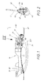
- Fig. 1
- eine Seitenansicht der Betätigungsvorrichtung, deren einer Bauteil, nämlich ein Träger, bereits an der Tür befestigt ist, wobei der Verlauf der Außenverkleidung der Tür verdeutlicht ist, dabei wurde auch ein zur Betätigungsvorrichtung gehörender Griff von der Türaußenseite aus montiert und im Träger gelagert,
- Fig. 2
- in perspektivischer Darstellung einen zweiten Bestandteil der Betätigungsvorrichtung, nämlich einen Turm, der in die Vorrichtung von Fig. 1 noch montiert werden soll,
- Fig. 3
- eine perspektivische rückseitige Ansicht des Trägers von Fig. 1 in Blickrichtung des dortigen Pfeils III von Fig. 1,
- Fig. 4
- einen Längsschnitt durch den Träger von Fig. 3 längs der dortigen versprungenen Schnittlinie IV - IV, wobei der Griff zwecks Vereinfachung des nachfolgenden Einbaus des Turms betätigt worden ist,
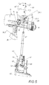
- Fig. 5
- ein weiterer Längsschnitt durch den Träger von Fig. 3 längs der versetzten Schnittlinie V - V von Fig. 3, wobei auch der Turm von Fig. 2 zu Beginn der Einrenkbewegung bei seiner Montage im Träger eingezeichnet ist,
- Fig. 6 + 7
- analoge Schnitt- bzw. Seitenansichten zu Fig. 5, die zwei weitere Phasen im Vollzug der Einrenkbewegung bei der Montage des Turms veranschaulichen,
- Fig. 8
- in einer zu Fig. 1 analogen Darstellung die fertige Betätigungsvorrichtung, wo der Turm im Träger montiert ist,
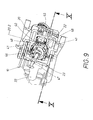
- Fig. 9
- eine perspektivische Ansicht von hinten auf die fertige Betätigungsvorrichtung von Fig. 8 in Blickrichtung des dortigen Pfeils IX und
- Fig. 10,
- in Analogie zu Fig. 4, einen versprungenen Längsschnitt durch die fertig montierte Betätigungsvorrichtung von Fig. 8 längs der Schnittlinie X - X von Fig. 9, wobei die Türaußenverkleidung weggelassen wurde.
- 10
- Träger
- 11
- Vorderseite von 10
- 12
- Rückseite von 10
- 13
- Gegenschulter an 14 (Fig. 5)
- 14
- Nase für 13 (Fig. 5)
- 15
- Öffnung in 10 für 40 (Fig. 3)
- 16
- Pfeil der Federkraft zwischen 20 und 10 (Fig. 4)
- 17
- Sicherungsschraube (Fig. 7)
- 18
- Betätigungsende von 17 (Fig. 7)
- 19
- Schraubenschaft von 17 (Fig. 7)
- 20
- Schieber
- 20.1
- Entsicherungsposition von 20 (Fig. 1 bis Fig. 7)
- 20.2
- Verriegelungsposition von 20 (Fig. 9, 10)
- 21
- Sperrfläche an 20
- 22
- Ausschnitt in 20 (Fig. 3, 9)
- 23
- Kipphebel, Kippbügel
- 23.1
- Ausgangslage von 23 (Fig. 1 bis 4)
- 23.2
- erste Zwischenlage von 23 (Fig. 6)
- 23.3
- zweite Zwischenlage von 23 (Fig. 7)
- 23.4
- Endlage von 23
- 24
- Bügelschenkel von 23 (Fig. 3, 4)
- 25
- Schwenkachse von 23 (Fig. 4)
- 26
- Druckfläche an 23 (Fig. 4)
- 27
- Steuernocken an 24 (Fig. 4)
- 28
- Steuerfläche von 27 (Fig. 4)
- 29
- Steuer-Gegenfläche an 20 (Fig. 4)
- 30
- Griff
- 30.1
- Ruhestellung von 30 (Fig. 1, 4)
- 30.2
- Betätigungsstellung von 30 (Fig. 4)
- 31
- Lagerende von 30 (Fig. 1)
- 32
- Arm von 30 (Fig. 4)
- 33
- Mitnehmer an 32 (Fig. 3, 4)
- 34
- Pfeil der Griffbetätigung von 30 (Fig. 4)
- 35
- Schwenkbewegungs-Pfeil von 23 (Fig. 4)
- 35'
- Pfeil der Rückschwenkung von 23 (Fig. 10)
- 36
- Haltemittel, Lasche (Fig. 4)
- 37
- Haltemittel, zweite Lasche (Fig. 4)
- 38
- Haltemittel, erster Bolzen in 36 (Fig. 4)
- 39
- Haltemittel, zweiter Bolzen in 37 (Fig. 4)
- 40
- Turm
- 41
- Gegensperrfläche in 48 (Fig. 5)
- 42
- Radialvorsprung an 43 (Fig. 2, 5)
- 43
- Schulter bei 42 (Fig. 5)
- 44
- Schließzylinder (Fig. 5)
- 45
- Turmkopf (Fig. 5)
- 46
- Zylindergehäuse (Fig. 5)
- 47
- Schaft an 44 (Fig. 5)
- 48
- Ausnehmung in 46 für 41 (Fig. 5)
- 49
- Doppelpfeil der Verschiebung von 20 (Fig. 4)
- 50
- Tür (Fig. 1)
- 51
- Türaußenverkleidung (Fig. 1)
- 52
- erster Durchbruch in 51 für 31 (Fig. 1)
- 53
- zweiter Durchbruch in 51 für 32 (Fig. 1)
- 54
- Schraubenende von 17 (Fig. 7)
- 55
- Loch für 19 in 10 (Fig. 7)
- 56
- Ansatz an 20 für 18 (Fig. 7)
- 57
- Gewindeaufnahme in 45 für 52 (Fig. 7)
- 58
- Führung in 36 für 38 (Fig. 4)
- 59
- Führung in 37 für 39 (Fig. 4)
- 60
- Einrenkbewegung bei Demontage von 40 (Fig. 5)
- 60'
- rückläufige Einrenkbewegung bei Demontage von 40 (Fig. 5, 10)
- 61
- erste Bewegungskomponente von 60, Einsteckphase (Fig. 5)
- 61'
- Ausziehphase von 40 bei 60'
- 62
- zweite Bewegungskomponente von 60, Versetzphase von 40 (Fig. 5)
- 62'
- rückläufige Versetzphase von 40 bei 60' (Fig. 5, 10)
- 63
- Pfeil der Ausreißkraft von 40 aus 10 (Fig. 8, 10)
- 64
- Kerbe in 27 für 29 (Fig. 4, 10)
Claims (18)
- Betätigungsvorrichtung für Türen (50) oder Klappen an Fahrzeugen,
mit einem Träger (10), der im Türinneren befestigbar ist,
mit einem entweder einen Schließzylinder (44) oder eine Styling-Attrappe aufweisenden Turm (40),
der im Träger (10) mittels einer Einrenkbewegung (60, 60') montierbar (60) und/oder demontierbar (60') ist,
wobei die Einrenkbewegung (60, 60') des Turms (40) aus zwei Bewegungskomponenten besteht und erstens eine Einsteckphase (61) zur Montage bzw. eine Ausziehphase (61') zur Demontage umfasst, wo der Turm (40) in eine Öffnung (15) im Träger (10) eingesteckt bzw. aus der Öffnung herausgezogen wird,
und zweitens eine quer zum Einstecken (61) bzw. Ausziehen (61') verlaufende Versetzphase (62, 62') durchläuft, wo der Turm (40) im Träger (10) soweit parallel-versetzt wird, bis mindestens eine seitliche Schulter (43) am Turm (40) bei der Montage hinter eine Gegenschulter (13) am Träger (10) fährt bzw. bei der Demontage aus der Schulter (43) herausgelangt,
und mit einer verschraubbaren Sicherungsschraube (17), welche den montierten Turm (40) im Träger (10) sichert,
dadurch gekennzeichnet , dass im Träger (10) ein Kipphebel (23) schwenkgelagert (25) ist, der sowohl eine Steuerkurve (28) als auch eine Druckfläche (26) aufweist und der zwischen einer Ausgangslage (23.1) und einer Endlage (23.4) verschwenkbar ist,
dass die Steuerkurve (28) bei Schwenkbetätigung (35, 35') des Kipphebels (23) einen im Träger (10) geführten Schieber (20) zwischen zwei Positionen (20.1, 20.2) verschiebt (49),
nämlich einerseits einer Entriegelungsposition (20.1) in der Ausgangslage (23.1) des Kipphebels (23), wo eine am Schieber (20) befindliche Sperrfläche (21) eine Gegensperrfläche (41) am Turm (40) freigibt,
und andererseits einer Verriegelungsposition (20.2) in der Endlage (23.4) des Kipphebels (23), wo die Sperrfläche (21) vom Schieber (20) die Gegensperrfläche (41) hintergreift und den Turm (40) im Träger (10) verriegelt,
dass vor der Montage des Turms (40) der Kipphebel (23) sich in seiner Ausgangslage (23.1) und der Schieber (20) in seiner Entriegelungsposition (20.1) befinden,
dass zur Montage bei der Einsteckphase (61) der Turm (40) gegen die Druckfläche (26) stößt und den Kipphebel (23) in Richtung seiner Endlage (23.4) verschwenkt (35), die der Kipphebel (23) nach Vollzug der Versetzphase (62) vom Turm (40) im Träger (10) erreicht,
dass die Sicherungsschraube (17) die Verriegelungsposition (20.2) des Schiebers (20) am Träger (10) sichert und dann der Sicherungsfall vorliegt, während die Sicherungsschraube (17) im Entsicherungsfall den Schieber (20) zur Verschiebung (49) im Träger freigibt
und dass zur Demontage des Turms (40) der Kipphebel (23) aus seiner Endlage (23.4) manuell zurückgeschwenkt (35') wird,
wobei einerseits die Steuerkurve (28) vom Kipphebel (23) den Schieber (20) bis zur Entriegelungsposition (20.1) zurückschiebt und andererseits die Druckfläche (26) vom Kipphebel (23) den Turm (40) im Träger (10) bis zum Start der Ausziehphase (62') zurücksetzt. - Vorrichtung nach Anspruch 1, dadurch gekennzeichnet, dass der Kipphebel (23) und sein Betätigungsende sich auf der Rückseite (23) des Trägers (10) befinden,
wobei die Rückseite (12) derjenigen Vorderseite (11) des Trägers (10) gegenüberliegt, von welcher aus der Turm (40) bei der Montage eingesteckt (61) wird. - Vorrichtung nach Anspruch 1 oder 2, dadurch gekennzeichnet, dass die Verschiebungsrichtung des Schiebers (20) aus dessen Entriegelungsposition (20.1) in die Verriegelungsposition (20.2), die gleiche ist, wie die Parallelversetzung des Turms (40) während der Verschiebungsphase (62, 62') im Träger (10), wo bei der Montage die Schulter (43) am Turm (40) hinter die Gegenschulter (13) am Träger (10) fährt bzw. bei der Demontage wieder herausgelangt.
- Betätigungsvorrichtung nach einem oder mehreren der Ansprüche 1 bis 3, dadurch gekennzeichnet, dass der Kipphebel (23) einen Nocken (Steuernocken 27) besitzt, dessen Umfangsprofil die Steuerkurve (28) bildet,
und dass der Schieber (20) Steuergegenflächen (29) besitzt, die mit der Steuerkurve (28) des Kipphebels (23) kraftschlüssig zusammenwirken. - Vorrichtung nach einem oder mehreren der Ansprüche 1 bis 4, dadurch gekennzeichnet, dass zwischen dem Schieber (20) und dem Träger (10) eine Federbelastung (16) wirkt,
die bestrebt ist, den Schieber (20) aus seiner Entriegelungsposition (20.1) in seine Verriegelungsposition (20.2) zu verschieben. - Vorrichtung nach Anspruch 5, dadurch gekennzeichnet, dass die Federbelastung (16) des Schiebers (20) bestrebt ist, den Kipphebel (23) in dessen Endlage (23.4) zurückzudrücken.
- Vorrichtung nach einem der Ansprüche 4, 5 oder 6, dadurch gekennzeichnet, dass der Steuernocken (27) vom Kipphebel (23) eine Kerbe (64) aufweist, in welche ein Anfangsstück (29) vom Schieber (20) in der Verriegelungsposition (20.2) einfährt und den Kipphebel (23) in dessen Endlage (23.4) verrastet.
- Vorrichtung nach einem oder mehreren der Ansprüche 1 bis 7, dadurch gekennzeichnet, dass der Schieber (20) auf der Rückseite (12) des Trägers (10) aufliegt und bei seiner Verschiebung (49) auf der Träger-Rückseite (12) gleitet
und dass das die Gleitfläche erzeugende Trägermaterial den Schieber (20) gegenüber Ausreißkräften (63) verstärkt, die bei Einbruchsversuchen auf den verriegelten Turm (40) einwirken. - Vorrichtung nach Anspruch 8, dadurch gekennzeichnet, dass der Schieber (20) durch Haltemittel (36 bis 39) mit dem Träger (10) verbunden ist.
- Vorrichtung nach Anspruch 9, dadurch gekennzeichnet, dass die Haltemittel aus mindestens einem im Träger (10) sitzenden Bolzen (38, 39) bestehen, der in eine Führung (58, 59) eines am Schlitten vorgesehenen Lappens (36, 37) eingreift.
- Vorrichtung nach einem oder mehreren der Ansprüche 1 bis 10, dadurch gekennzeichnet, dass der Kipphebel ein Bügel (Kippbügel 23) ist,
der mit seinen beiden Bügel-Schenkeln (24) am Träger (10) gemeinsam schwenkgelagert (25) ist
und dass zwischen den beiden Bügelschenkeln (24) die zum Einstecken (61) des Turms (20) dienende Öffnung (15) im Träger (10) angeordnet ist. - Vorrichtung nach Anspruch 11, dadurch gekennzeichnet, dass im Bereich der Lagerenden (25) der Bügel-Schenkel (24) der Steuernocken (27) sitzt, der bei Betätigung (35') des Kippbügels (23) auf den Schieber (20) wirkt.
- Vorrichtung nach Anspruch 11 oder 12, dadurch gekennzeichnet, dass die Druckfläche (26) zum Verschwenken des Kippbügels (23) bei der Montage (60) des Turms (40) und/oder zum Zurücksetzen (62') des Turms (40) bei der Demontage (60') im Bereich des Stegs vom Kippbügel (23) angeordnet ist.
- Vorrichtung nach Anspruch 11, 12 oder 13, dadurch gekennzeichnet, dass der Schieber (20) zwei in seitlichem Abstand zueinander angeordnete Sperrflächen (21) besitzt, zwischen die in der Verriegelungsposition (20.2) der Turm (40) mit zwei Ausnehmungen (48) gelangt, welche zwei Gegensperrflächen (41) bilden.
- Vorrichtung nach einem oder mehreren der Ansprüche 1 bis 14, dadurch gekennzeichnet, dass der Turm (40) zwei beabstandete Radialvorsprünge (42) mit je einem Einschnitt aufweist, dessen eine Einschnitt-Flanke jeweils die Schulter (43) am Turm (40) bildet,
und dass den Einschnitten zwei Nasen (14) am Träger (10) zugeordnet sind, die bei der Montage (62) und Demontage (62') des Turms (40) als Gegenschultern (13) fungieren. - Vorrichtung nach einem oder mehreren der Ansprüche 1 bis 15, dadurch gekennzeichnet, dass der Träger (10) ein Loch (55) für die Sicherungsschraube (17) aufweist, deren Betätigungsende (18) sich an der Rückseite (12) des Trägers (10) befindet
und dass das dem Betätigungsende (19) gegenüberliegende Schraubende (54) dann mit einer Gewindebohrung (57) im Turm (40, 45) ausgerichtet ist, wenn die Einrenkbewegung (60) beendet ist, worauf das Schraubenende (54) in die Gewindebohrung (57) verschraubbar ist. - Vorrichtung nach Anspruch 16, dadurch gekennzeichnet, dass das Betätigungsende der Sicherungsschraube (17) in der Entriegelungsposition (20.1) vom Schieber (20) unzugänglich (56), aber in der Verriegelungsposition (20.2) zugänglich ist.
- Vorrichtung nach einem oder mehreren der Ansprüche 1 bis 15, dadurch gekennzeichnet, dass der Schieber (20) ein Loch für die Sicherungsschraube (17) aufweist,
dass das Loch mit einem weiteren Loch im Träger dann ausgerichtet ist, wenn die Verriegelungsposition (20.2) vom Schieber (20) vorliegt,
und dass das Schraubenende der Sicherungsschraube (17) in eine Gewindebohrung des Turms dann verschraubbar ist, wenn die Einrenkbewegung (60) des Turms (40) abgeschlossen ist.
Applications Claiming Priority (2)
| Application Number | Priority Date | Filing Date | Title |
|---|---|---|---|
| DE200410001894 DE102004001894B4 (de) | 2004-01-14 | 2004-01-14 | Betätigungsvorrichtung für Türen oder Klappen an Fahrzeugen |
| DE102004001894 | 2004-01-14 |
Publications (2)
| Publication Number | Publication Date |
|---|---|
| EP1555363A1 true EP1555363A1 (de) | 2005-07-20 |
| EP1555363B1 EP1555363B1 (de) | 2007-01-10 |
Family
ID=34609531
Family Applications (1)
| Application Number | Title | Priority Date | Filing Date |
|---|---|---|---|
| EP20040029008 Expired - Lifetime EP1555363B1 (de) | 2004-01-14 | 2004-12-08 | Betätigungsvorrichtung für Türen oder Klappen an Fahrzeugen |
Country Status (3)
| Country | Link |
|---|---|
| US (1) | US7146832B2 (de) |
| EP (1) | EP1555363B1 (de) |
| DE (2) | DE102004001894B4 (de) |
Cited By (4)
| Publication number | Priority date | Publication date | Assignee | Title |
|---|---|---|---|---|
| WO2013013751A1 (de) * | 2011-07-28 | 2013-01-31 | Audi Ag | Türgriffanordnung für ein fahrzeug |
| CN102953583A (zh) * | 2011-08-24 | 2013-03-06 | 胡夫·许尔斯贝克和福斯特有限及两合公司 | 车辆的车门把手设施 |
| CN103195315A (zh) * | 2012-01-06 | 2013-07-10 | 江苏皓月汽车锁股份有限公司 | 汽车左前门锁体 |
| WO2018153531A1 (de) * | 2017-02-24 | 2018-08-30 | Huf Hülsbeck & Fürst Gmbh & Co. Kg | HANDHABE MIT EINER BEWEGLICHEN SCHLIEßZYLINDEREINHEIT |
Families Citing this family (16)
| Publication number | Priority date | Publication date | Assignee | Title |
|---|---|---|---|---|
| JP4645324B2 (ja) * | 2005-06-29 | 2011-03-09 | 三菱自動車工業株式会社 | 車両用ドア |
| EP2076643B1 (de) * | 2006-08-26 | 2010-07-28 | Huf Hülsbeck & Fürst GmbH & Co. KG | Vorrichtung zur betätigung eines schlosses in der tür oder klappe eines fahrzeugs |
| US9181733B2 (en) * | 2010-01-28 | 2015-11-10 | Kabushiki Kaisha Honda Lock | Vehicle door handle system |
| US8632116B2 (en) * | 2010-08-31 | 2014-01-21 | GM Global Technology Operations LLC | Anti-theft device for an access door |
| CN103917728B (zh) * | 2011-06-20 | 2016-03-30 | Adac塑模公司 | 门把手组件、子组件及其安装方法 |
| US20130257065A1 (en) * | 2012-03-29 | 2013-10-03 | B/E Aerospace, Inc. | Cart bay door paddle latch |
| JP5932609B2 (ja) * | 2012-11-08 | 2016-06-08 | 株式会社ホンダロック | 車両用ドアのアウトハンドル装置 |
| JP6133624B2 (ja) * | 2013-02-28 | 2017-05-24 | サカエ理研工業株式会社 | ドア施開錠操作装置及び車両ドア用キーシリンダ組み付けパーツ |
| DE102013016606B4 (de) * | 2013-10-07 | 2017-05-24 | D. la Porte Söhne GmbH | Ziehgriff für eine Fahrzeugtür |
| DE102013016607B4 (de) * | 2013-10-07 | 2017-05-04 | D. la Porte Söhne GmbH | Ziehgriff für eine Fahrzeugtür |
| US10196842B2 (en) | 2014-06-20 | 2019-02-05 | Huf North America Automotive Parts Manufacturing Corp. | Retention mechanism for insertion member in vehicular door handle assembly |
| US9145712B1 (en) * | 2014-12-17 | 2015-09-29 | I-Tek Metal Mfg. Co., Ltd. | Lock cylinder for a door lock |
| US10145151B2 (en) * | 2015-04-30 | 2018-12-04 | Huf North America Automotive Parts Manufacturing Corp. | Retention mechanism for vehicular door handle assembly |
| DE102017126032B4 (de) * | 2017-11-08 | 2025-11-13 | Dr. Ing. H.C. F. Porsche Aktiengesellschaft | Schließvorrichtung |
| DE102017129431A1 (de) | 2017-12-11 | 2019-06-13 | Brose Fahrzeugteile Gmbh & Co. Kommanditgesellschaft, Bamberg | Türgriffeinheit |
| EP4108865B1 (de) * | 2021-06-24 | 2025-11-19 | Minebea AccessSolutions France | Fahrzeugtürgriffanordnung |
Citations (3)
| Publication number | Priority date | Publication date | Assignee | Title |
|---|---|---|---|---|
| DE3030519A1 (de) * | 1980-08-13 | 1982-02-18 | Daimler-Benz Ag, 7000 Stuttgart | Aussenliegender ziehgriff, insbesondere fuer kraftfahrzeugtueren |
| EP1099817A1 (de) * | 1999-11-12 | 2001-05-16 | Valeo Sicurezza Abitacolo S.p.A. | Türgriff für Kraftfahrzeug |
| EP1176271A2 (de) * | 2000-07-26 | 2002-01-30 | Volkswagen Aktiengesellschaft | Vorrichtung zur Arretierung eines Schliesszylindergehäuses |
Family Cites Families (9)
| Publication number | Priority date | Publication date | Assignee | Title |
|---|---|---|---|---|
| US2040258A (en) * | 1934-08-27 | 1936-05-12 | Briggs & Stratton Corp | Mounting means for automobile doorlocks |
| DE19826778A1 (de) * | 1998-06-11 | 1999-12-23 | Brose Fahrzeugteile | Vorrichtung zum Verbinden eines Außengriffs mit einem Schließsystem |
| FR2789426B1 (fr) * | 1999-02-05 | 2001-06-15 | Valeo Securite Habitacle | Poignee d'ouvrant de vehicule automobile |
| FR2789428B1 (fr) * | 1999-02-05 | 2001-04-13 | Valeo Securite Habitacle | Poignee d'ouvrant de vehicule automobile comportant des moyens perfectionnes de blocage d'un element externe |
| JP4345128B2 (ja) * | 1999-03-30 | 2009-10-14 | アイシン精機株式会社 | 車両用ドアロック操作システム及び該車両ドアロック操作システムを備えた車両ドア |
| DE19950172B4 (de) * | 1999-10-19 | 2009-02-12 | Huf Hülsbeck & Fürst Gmbh & Co. Kg | Griffbeschlag, insbesondere für eine Kraftfahrzeugtür |
| US6494066B2 (en) * | 2001-03-09 | 2002-12-17 | U-Shin Ltd. | Cylinder lock mounting device |
| US6523379B2 (en) * | 2001-04-20 | 2003-02-25 | Ryadon, Inc. | Locking cylinder and housing |
| DE10146026C1 (de) * | 2001-09-18 | 2002-10-31 | Huf Huelsbeck & Fuerst Gmbh | Griffbeschlag |
-
2004
- 2004-01-14 DE DE200410001894 patent/DE102004001894B4/de not_active Expired - Fee Related
- 2004-12-08 EP EP20040029008 patent/EP1555363B1/de not_active Expired - Lifetime
- 2004-12-08 DE DE200450002614 patent/DE502004002614D1/de not_active Expired - Lifetime
-
2005
- 2005-01-07 US US11/031,681 patent/US7146832B2/en not_active Expired - Lifetime
Patent Citations (3)
| Publication number | Priority date | Publication date | Assignee | Title |
|---|---|---|---|---|
| DE3030519A1 (de) * | 1980-08-13 | 1982-02-18 | Daimler-Benz Ag, 7000 Stuttgart | Aussenliegender ziehgriff, insbesondere fuer kraftfahrzeugtueren |
| EP1099817A1 (de) * | 1999-11-12 | 2001-05-16 | Valeo Sicurezza Abitacolo S.p.A. | Türgriff für Kraftfahrzeug |
| EP1176271A2 (de) * | 2000-07-26 | 2002-01-30 | Volkswagen Aktiengesellschaft | Vorrichtung zur Arretierung eines Schliesszylindergehäuses |
Cited By (8)
| Publication number | Priority date | Publication date | Assignee | Title |
|---|---|---|---|---|
| WO2013013751A1 (de) * | 2011-07-28 | 2013-01-31 | Audi Ag | Türgriffanordnung für ein fahrzeug |
| CN102953583A (zh) * | 2011-08-24 | 2013-03-06 | 胡夫·许尔斯贝克和福斯特有限及两合公司 | 车辆的车门把手设施 |
| EP2562338A3 (de) * | 2011-08-24 | 2015-01-21 | Huf Hülsbeck & Fürst GmbH & Co. KG | Türgriffanordnung eines Kraftfahrzeugs |
| CN102953583B (zh) * | 2011-08-24 | 2016-08-17 | 胡夫·许尔斯贝克和福斯特有限及两合公司 | 车辆的车门把手设施 |
| CN103195315A (zh) * | 2012-01-06 | 2013-07-10 | 江苏皓月汽车锁股份有限公司 | 汽车左前门锁体 |
| WO2018153531A1 (de) * | 2017-02-24 | 2018-08-30 | Huf Hülsbeck & Fürst Gmbh & Co. Kg | HANDHABE MIT EINER BEWEGLICHEN SCHLIEßZYLINDEREINHEIT |
| CN110582611A (zh) * | 2017-02-24 | 2019-12-17 | 霍富许尔斯贝克和富斯特有限及两合公司 | 具有可移动的锁芯单元的手柄 |
| CN110582611B (zh) * | 2017-02-24 | 2021-09-07 | 霍富许尔斯贝克和富斯特有限及两合公司 | 具有可移动的锁芯单元的手柄 |
Also Published As
| Publication number | Publication date |
|---|---|
| DE102004001894A1 (de) | 2005-08-11 |
| DE502004002614D1 (de) | 2007-02-22 |
| DE102004001894B4 (de) | 2006-03-23 |
| US20050178176A1 (en) | 2005-08-18 |
| US7146832B2 (en) | 2006-12-12 |
| EP1555363B1 (de) | 2007-01-10 |
Similar Documents
| Publication | Publication Date | Title |
|---|---|---|
| EP1555363B1 (de) | Betätigungsvorrichtung für Türen oder Klappen an Fahrzeugen | |
| DE4412609A1 (de) | Verschlußvorrichtung für insbesondere an Kraftfahrzeugen vollziehbare Schließfunktionen | |
| EP1473423A2 (de) | Türaussengriff, insbesondere für Fahrzeuge | |
| DE10022373A1 (de) | Verriegelungs- und Betätigungseinheit für seitliche Auslegerverriegelung | |
| EP0816603A2 (de) | Selbstverriegelndes Panikschloss | |
| DE10335311B4 (de) | Lenkschlossvorrichtung | |
| EP0653535B1 (de) | Schloss | |
| EP1408186A1 (de) | Vorrichtung zur Betätigung eines Verschlusses von Türen, Klappen od. dgl., insbesondere an Fahrzeugen | |
| EP1548213B1 (de) | Betätigungsvorrichtung für Türen oder Klappen an Fahrzeugen | |
| DE10320439A1 (de) | Kraftfahrzeugtürverschluss | |
| DE60009373T2 (de) | Treibstangenschloss enthaltend einen Hakenriegel mit Mitteln zur Riegelblockierung | |
| EP2060714A2 (de) | Treibstangenschloss | |
| EP1947275B1 (de) | Schloss | |
| DE4202698A1 (de) | Verschluss fuer tueren, hauben o. dgl., insbesondere von fahrzeugen, wie kraftfahrzeugen | |
| DE10151870A1 (de) | Vorrichtung zur Betätigung eines Verschlusses von Türen oder Klappen, insbesondere an Fahrzeugen | |
| EP1473427B1 (de) | Sicherheitszuhaltung | |
| EP1671002B1 (de) | Schliesszylinder für ein schloss, insbesondere bei fahrzeugen | |
| EP1505227A2 (de) | Vorrichtung zur Betätigung eines Schlosses an einer Tür oder Klappe eines Fahrzeugs | |
| DE29803239U1 (de) | Türschließvorrichtung | |
| EP1580352A2 (de) | Betätigungsvorrichtung für Türen oder Klappen | |
| EP0681950B1 (de) | Vorrichtung mit einem Wählhebel für Kraftfahrzeug-Automatikgetriebe | |
| DE3534523C2 (de) | Lenkradschloß | |
| EP0675250B1 (de) | Schloss, insbesondere Treibstangenschloss oder dergleichen | |
| EP1632627B1 (de) | Betätigungsvorrichtung für Türen oder Klappen an Fahrzeugen | |
| EP1526237A1 (de) | Vorrichtung zum Verriegeln und zum Betätigen von Klappen, Türen oder dgl. |
Legal Events
| Date | Code | Title | Description |
|---|---|---|---|
| PUAI | Public reference made under article 153(3) epc to a published international application that has entered the european phase |
Free format text: ORIGINAL CODE: 0009012 |
|
| AK | Designated contracting states |
Kind code of ref document: A1 Designated state(s): AT BE BG CH CY CZ DE DK EE ES FI FR GB GR HU IE IS IT LI LT LU MC NL PL PT RO SE SI SK TR |
|
| AX | Request for extension of the european patent |
Extension state: AL BA HR LV MK YU |
|
| 17P | Request for examination filed |
Effective date: 20050614 |
|
| AKX | Designation fees paid |
Designated state(s): AT BE BG CH CY CZ DE DK EE ES FI FR GB GR HU IE IS IT LI LT LU MC NL PL PT RO SE SI SK TR |
|
| GRAP | Despatch of communication of intention to grant a patent |
Free format text: ORIGINAL CODE: EPIDOSNIGR1 |
|
| GRAS | Grant fee paid |
Free format text: ORIGINAL CODE: EPIDOSNIGR3 |
|
| GRAA | (expected) grant |
Free format text: ORIGINAL CODE: 0009210 |
|
| AK | Designated contracting states |
Kind code of ref document: B1 Designated state(s): AT BE BG CH CY CZ DE DK EE ES FI FR GB GR HU IE IS IT LI LT LU MC NL PL PT RO SE SI SK TR |
|
| PG25 | Lapsed in a contracting state [announced via postgrant information from national office to epo] |
Ref country code: SI Free format text: LAPSE BECAUSE OF FAILURE TO SUBMIT A TRANSLATION OF THE DESCRIPTION OR TO PAY THE FEE WITHIN THE PRESCRIBED TIME-LIMIT Effective date: 20070110 Ref country code: FI Free format text: LAPSE BECAUSE OF FAILURE TO SUBMIT A TRANSLATION OF THE DESCRIPTION OR TO PAY THE FEE WITHIN THE PRESCRIBED TIME-LIMIT Effective date: 20070110 Ref country code: PL Free format text: LAPSE BECAUSE OF FAILURE TO SUBMIT A TRANSLATION OF THE DESCRIPTION OR TO PAY THE FEE WITHIN THE PRESCRIBED TIME-LIMIT Effective date: 20070110 Ref country code: NL Free format text: LAPSE BECAUSE OF FAILURE TO SUBMIT A TRANSLATION OF THE DESCRIPTION OR TO PAY THE FEE WITHIN THE PRESCRIBED TIME-LIMIT Effective date: 20070110 Ref country code: IE Free format text: LAPSE BECAUSE OF FAILURE TO SUBMIT A TRANSLATION OF THE DESCRIPTION OR TO PAY THE FEE WITHIN THE PRESCRIBED TIME-LIMIT Effective date: 20070110 Ref country code: DK Free format text: LAPSE BECAUSE OF FAILURE TO SUBMIT A TRANSLATION OF THE DESCRIPTION OR TO PAY THE FEE WITHIN THE PRESCRIBED TIME-LIMIT Effective date: 20070110 |
|
| REG | Reference to a national code |
Ref country code: GB Ref legal event code: FG4D Free format text: NOT ENGLISH |
|
| REG | Reference to a national code |
Ref country code: IE Ref legal event code: FG4D Free format text: LANGUAGE OF EP DOCUMENT: GERMAN |
|
| REF | Corresponds to: |
Ref document number: 502004002614 Country of ref document: DE Date of ref document: 20070222 Kind code of ref document: P |
|
| PG25 | Lapsed in a contracting state [announced via postgrant information from national office to epo] |
Ref country code: SE Free format text: LAPSE BECAUSE OF FAILURE TO SUBMIT A TRANSLATION OF THE DESCRIPTION OR TO PAY THE FEE WITHIN THE PRESCRIBED TIME-LIMIT Effective date: 20070410 Ref country code: BG Free format text: LAPSE BECAUSE OF FAILURE TO SUBMIT A TRANSLATION OF THE DESCRIPTION OR TO PAY THE FEE WITHIN THE PRESCRIBED TIME-LIMIT Effective date: 20070410 |
|
| PG25 | Lapsed in a contracting state [announced via postgrant information from national office to epo] |
Ref country code: ES Free format text: LAPSE BECAUSE OF FAILURE TO SUBMIT A TRANSLATION OF THE DESCRIPTION OR TO PAY THE FEE WITHIN THE PRESCRIBED TIME-LIMIT Effective date: 20070421 |
|
| PG25 | Lapsed in a contracting state [announced via postgrant information from national office to epo] |
Ref country code: IS Free format text: LAPSE BECAUSE OF FAILURE TO SUBMIT A TRANSLATION OF THE DESCRIPTION OR TO PAY THE FEE WITHIN THE PRESCRIBED TIME-LIMIT Effective date: 20070510 |
|
| ET | Fr: translation filed | ||
| PG25 | Lapsed in a contracting state [announced via postgrant information from national office to epo] |
Ref country code: PT Free format text: LAPSE BECAUSE OF FAILURE TO SUBMIT A TRANSLATION OF THE DESCRIPTION OR TO PAY THE FEE WITHIN THE PRESCRIBED TIME-LIMIT Effective date: 20070611 |
|
| NLV1 | Nl: lapsed or annulled due to failure to fulfill the requirements of art. 29p and 29m of the patents act | ||
| GBV | Gb: ep patent (uk) treated as always having been void in accordance with gb section 77(7)/1977 [no translation filed] |
Effective date: 20070110 |
|
| REG | Reference to a national code |
Ref country code: IE Ref legal event code: FD4D |
|
| PLBE | No opposition filed within time limit |
Free format text: ORIGINAL CODE: 0009261 |
|
| STAA | Information on the status of an ep patent application or granted ep patent |
Free format text: STATUS: NO OPPOSITION FILED WITHIN TIME LIMIT |
|
| PG25 | Lapsed in a contracting state [announced via postgrant information from national office to epo] |
Ref country code: SK Free format text: LAPSE BECAUSE OF FAILURE TO SUBMIT A TRANSLATION OF THE DESCRIPTION OR TO PAY THE FEE WITHIN THE PRESCRIBED TIME-LIMIT Effective date: 20070110 Ref country code: GB Free format text: LAPSE BECAUSE OF FAILURE TO SUBMIT A TRANSLATION OF THE DESCRIPTION OR TO PAY THE FEE WITHIN THE PRESCRIBED TIME-LIMIT Effective date: 20070110 |
|
| 26N | No opposition filed |
Effective date: 20071011 |
|
| PG25 | Lapsed in a contracting state [announced via postgrant information from national office to epo] |
Ref country code: RO Free format text: LAPSE BECAUSE OF FAILURE TO SUBMIT A TRANSLATION OF THE DESCRIPTION OR TO PAY THE FEE WITHIN THE PRESCRIBED TIME-LIMIT Effective date: 20070110 Ref country code: CZ Free format text: LAPSE BECAUSE OF FAILURE TO SUBMIT A TRANSLATION OF THE DESCRIPTION OR TO PAY THE FEE WITHIN THE PRESCRIBED TIME-LIMIT Effective date: 20070110 |
|
| PG25 | Lapsed in a contracting state [announced via postgrant information from national office to epo] |
Ref country code: LT Free format text: LAPSE BECAUSE OF FAILURE TO SUBMIT A TRANSLATION OF THE DESCRIPTION OR TO PAY THE FEE WITHIN THE PRESCRIBED TIME-LIMIT Effective date: 20070110 |
|
| PG25 | Lapsed in a contracting state [announced via postgrant information from national office to epo] |
Ref country code: IT Free format text: LAPSE BECAUSE OF FAILURE TO SUBMIT A TRANSLATION OF THE DESCRIPTION OR TO PAY THE FEE WITHIN THE PRESCRIBED TIME-LIMIT Effective date: 20070110 Ref country code: GR Free format text: LAPSE BECAUSE OF FAILURE TO SUBMIT A TRANSLATION OF THE DESCRIPTION OR TO PAY THE FEE WITHIN THE PRESCRIBED TIME-LIMIT Effective date: 20070411 |
|
| BERE | Be: lapsed |
Owner name: HUF HULSBECK & FURST G.M.B.H. & CO. KG Effective date: 20071231 |
|
| PG25 | Lapsed in a contracting state [announced via postgrant information from national office to epo] |
Ref country code: MC Free format text: LAPSE BECAUSE OF NON-PAYMENT OF DUE FEES Effective date: 20071231 |
|
| PG25 | Lapsed in a contracting state [announced via postgrant information from national office to epo] |
Ref country code: BE Free format text: LAPSE BECAUSE OF NON-PAYMENT OF DUE FEES Effective date: 20071231 |
|
| PG25 | Lapsed in a contracting state [announced via postgrant information from national office to epo] |
Ref country code: EE Free format text: LAPSE BECAUSE OF FAILURE TO SUBMIT A TRANSLATION OF THE DESCRIPTION OR TO PAY THE FEE WITHIN THE PRESCRIBED TIME-LIMIT Effective date: 20070110 |
|
| PG25 | Lapsed in a contracting state [announced via postgrant information from national office to epo] |
Ref country code: AT Free format text: LAPSE BECAUSE OF NON-PAYMENT OF DUE FEES Effective date: 20071208 |
|
| PG25 | Lapsed in a contracting state [announced via postgrant information from national office to epo] |
Ref country code: CY Free format text: LAPSE BECAUSE OF FAILURE TO SUBMIT A TRANSLATION OF THE DESCRIPTION OR TO PAY THE FEE WITHIN THE PRESCRIBED TIME-LIMIT Effective date: 20070110 |
|
| REG | Reference to a national code |
Ref country code: CH Ref legal event code: PL |
|
| PG25 | Lapsed in a contracting state [announced via postgrant information from national office to epo] |
Ref country code: LU Free format text: LAPSE BECAUSE OF NON-PAYMENT OF DUE FEES Effective date: 20071208 |
|
| PG25 | Lapsed in a contracting state [announced via postgrant information from national office to epo] |
Ref country code: HU Free format text: LAPSE BECAUSE OF FAILURE TO SUBMIT A TRANSLATION OF THE DESCRIPTION OR TO PAY THE FEE WITHIN THE PRESCRIBED TIME-LIMIT Effective date: 20070711 Ref country code: TR Free format text: LAPSE BECAUSE OF FAILURE TO SUBMIT A TRANSLATION OF THE DESCRIPTION OR TO PAY THE FEE WITHIN THE PRESCRIBED TIME-LIMIT Effective date: 20070110 |
|
| PG25 | Lapsed in a contracting state [announced via postgrant information from national office to epo] |
Ref country code: LI Free format text: LAPSE BECAUSE OF NON-PAYMENT OF DUE FEES Effective date: 20081231 Ref country code: CH Free format text: LAPSE BECAUSE OF NON-PAYMENT OF DUE FEES Effective date: 20081231 |
|
| REG | Reference to a national code |
Ref country code: FR Ref legal event code: PLFP Year of fee payment: 12 |
|
| REG | Reference to a national code |
Ref country code: FR Ref legal event code: PLFP Year of fee payment: 13 |
|
| REG | Reference to a national code |
Ref country code: FR Ref legal event code: PLFP Year of fee payment: 14 |
|
| PGFP | Annual fee paid to national office [announced via postgrant information from national office to epo] |
Ref country code: FR Payment date: 20181221 Year of fee payment: 15 |
|
| PGFP | Annual fee paid to national office [announced via postgrant information from national office to epo] |
Ref country code: DE Payment date: 20191126 Year of fee payment: 16 |
|
| PG25 | Lapsed in a contracting state [announced via postgrant information from national office to epo] |
Ref country code: FR Free format text: LAPSE BECAUSE OF NON-PAYMENT OF DUE FEES Effective date: 20191231 |
|
| REG | Reference to a national code |
Ref country code: DE Ref legal event code: R119 Ref document number: 502004002614 Country of ref document: DE |
|
| PG25 | Lapsed in a contracting state [announced via postgrant information from national office to epo] |
Ref country code: DE Free format text: LAPSE BECAUSE OF NON-PAYMENT OF DUE FEES Effective date: 20210701 |